CN101820803A - Boiler for heating water in coffee machines - Google Patents
Boiler for heating water in coffee machinesDownload PDFInfo
- Publication number
- CN101820803A CN101820803ACN200880110701ACN200880110701ACN101820803ACN 101820803 ACN101820803 ACN 101820803ACN 200880110701 ACN200880110701 ACN 200880110701ACN 200880110701 ACN200880110701 ACN 200880110701ACN 101820803 ACN101820803 ACN 101820803A
- Authority
- CN
- China
- Prior art keywords
- boiler
- seat
- hot water
- cold water
- boiler body
- Prior art date
- Legal status (The legal status is an assumption and is not a legal conclusion. Google has not performed a legal analysis and makes no representation as to the accuracy of the status listed.)
- Granted
Links
- 235000013353coffee beverageNutrition0.000titleclaimsabstractdescription19
- 235000016213coffeeNutrition0.000titleclaimsabstractdescription18
- 239000008236heating waterSubstances0.000titleabstract2
- XLYOFNOQVPJJNP-UHFFFAOYSA-NwaterSubstancesOXLYOFNOQVPJJNP-UHFFFAOYSA-N0.000claimsabstractdescription58
- 235000015114espressoNutrition0.000claimsabstractdescription4
- 238000009413insulationMethods0.000claimsdescription4
- 229920003023plasticPolymers0.000claimsdescription2
- 239000004033plasticSubstances0.000claimsdescription2
- 238000010438heat treatmentMethods0.000abstractdescription11
- 238000005485electric heatingMethods0.000abstract2
- 238000010304firingMethods0.000description7
- 235000013361beverageNutrition0.000description6
- 238000007789sealingMethods0.000description3
- 229910001220stainless steelInorganic materials0.000description3
- 239000000463materialSubstances0.000description2
- 230000005540biological transmissionEffects0.000description1
- 230000000694effectsEffects0.000description1
- 238000005516engineering processMethods0.000description1
- 210000002683footAnatomy0.000description1
- 238000004519manufacturing processMethods0.000description1
- 230000001105regulatory effectEffects0.000description1
- 239000010935stainless steelSubstances0.000description1
Images


Classifications
- A—HUMAN NECESSITIES
- A47—FURNITURE; DOMESTIC ARTICLES OR APPLIANCES; COFFEE MILLS; SPICE MILLS; SUCTION CLEANERS IN GENERAL
- A47J—KITCHEN EQUIPMENT; COFFEE MILLS; SPICE MILLS; APPARATUS FOR MAKING BEVERAGES
- A47J31/00—Apparatus for making beverages
- A47J31/44—Parts or details or accessories of beverage-making apparatus
- A47J31/54—Water boiling vessels in beverage making machines
- A47J31/56—Water boiling vessels in beverage making machines having water-level controls; having temperature controls
- H—ELECTRICITY
- H05—ELECTRIC TECHNIQUES NOT OTHERWISE PROVIDED FOR
- H05B—ELECTRIC HEATING; ELECTRIC LIGHT SOURCES NOT OTHERWISE PROVIDED FOR; CIRCUIT ARRANGEMENTS FOR ELECTRIC LIGHT SOURCES, IN GENERAL
- H05B3/00—Ohmic-resistance heating
- H05B3/78—Heating arrangements specially adapted for immersion heating
- H05B3/82—Fixedly-mounted immersion heaters
Landscapes
- Engineering & Computer Science (AREA)
- Food Science & Technology (AREA)
- Apparatus For Making Beverages (AREA)
Abstract
Description
Technical field
The present invention relates to a kind of boiler of water being heated at coffee machine of being used for according to claim 1 preamble.
Background technology
Usually, these boilers are used in coffee machine and the espresso coffee machines (espresso machine), use in the machine especially for use in specialty.Boiler is roughly columniform container by sealing withstand voltage and the tubulose calandria that is positioned at container and forms the heat(ing) coil of fixed and arranged constitutes, and container has cold water inlet and hot water outlet.The water of adorning in the boiler is heated to the required temperature of infusing coffee, and is subjected to the pressure of about 10 crust magnitudes.When preparing beverage, from boiler, take out hot water, and the cold water of equivalent is flow to.In this way, the water temperature in the boiler descends.The heater that is located in the boiler provides Fast Heating for water, makes coffee machine be ready to operation at short notice once more, promptly can prepare the beverage of back.In specialty with in the machine, hope be after finishing a serving, can prepare a new beverage immediately.So be to produce from the stage that brewing of coffee machine prepared with coffee and coffee flows out circulation timei.Should not extend this circulation timei heat time heating time.In order to achieve this end, in boiler, used the high as far as possible heating element heater of electrical power.The shortcoming of the heating element heater of high heating efficiency is that the energy density at calandria place is very big, so heat can not be discharged into whole water body from heating element heater at all fast enough.The mutual position of the coil of tubulose calandria is very near, makes them influence each other, and promptly when heating tubulose calandria, heat not only is discharged into water, also is discharged into the coil that is close to.This usually causes hot-spot, produces steam bubble, and sometimes in addition can hear slight fizz.At the some place that this hot-spot takes place, because steam bubble is arranged, the heat transmission between tubulose calandria and the water is not than generating the steam bubble time difference, and this has caused the reduction of firing equipment efficient on the whole.
Summary of the invention
An object of the present invention is to provide a kind of boiler of water being heated at coffee machine of being used for, this boiler has overcome the above-mentioned shortcoming of conventional apparatus.
Above-mentioned purpose is to be realized by the boiler of the feature withclaim 1.
By means of following description,, further feature and advantage of the present invention are made an explanation especially with reference to accompanying drawing to preferred illustrative embodiments.
Description of drawings
In the accompanying drawings:
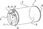
Fig. 1 is the perspective view of boiler body, and it has transparent body shell;
Fig. 2 is the perspective view of the boiler seat with firing equipment seen from the inboard;
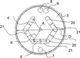
Fig. 3 illustrates the boiler seat of having assembled firing equipment with the view that obtains on the direction of boiler axis;
Fig. 4 is the perspective view of the boiler seat with firing equipment seen from the outside;
Fig. 5 is the schematic cross sectional views of passing water connector that can connector.
The specific embodiment
Principle according to boiler of the present invention is because the firing equipment of appropriate structuring and adiabatic boiler body are compared with traditional comparable coffee machine, can prepare required hot water amount with electric energy still less in the same time.This firing equipment preferably is made of the tubulose calandria, it roughly extends on the whole volume of boiler, like this, heat can as far as possible side by side and in equally distributed mode discharge feedwater on whole volume, and the hot-spot that can not have steam to produce.If expect whole volume is divided into little single unit, so, each part of tubulose calandria all will heat respectively simultaneously directly round the basic unit of quantity equally of this calandria or the same partial volume of boiler.In this way, for from the farther unit of calandria, as the situation in firing equipment usually, the time delay when by convection current water being heated has reduced greatly.The coil of tubulose calandria arranges like this and makes them no longer influence each other that therefore when heating tubulose calandria, heat only discharges to water basically.
A kind of exemplary embodiment according toboiler 1 of the present invention is shown schematically in the perspective view of Fig. 1.Columniform withstandvoltage boiler body 1 usefulness stainless steel manufacturing also has about 1 to 2 litercapacity.Boiler body 1 comprisesboiler shell 2 and the side that welds together with shell 2.These lateral vertical are arranged incylinder axis.Shell 2 is shown as transparent, can see thetubulose calandria 5 in theboiler 1 like this.One of side ofboiler body 1 forms boiler lid 4, the second sides and forms boiler seat 3.Boiler seat 3 is equipped with thepassage 7 that is used to connect cold water, thepassage 9 that is used for thepassage 8 of hot water outlet and is used for temperature sensor, and is furnished with theelectric connector 6 that is used for tubulose calandria 5.Boiler 1 is designed to levels operation, promptly is installed in the cylinder axis horizontal-extending of theboiler 1 in the coffee machine, and the boiler seat of arranging perpendicular tocylinder axis A 3 vertically extends.Boiler seat 3 further is oriented such that, and coldwater inlet pipeline 7 is positioned at its underpart, and in playing most below the circle oftubulose calandria 5, and hotwater outlet pipeline 8 is positioned at the top ofboiler seat 3, above theconnector 6 that is used for tubulose calandria 5.The next door that is close to the connector that is used for hotwater outlet pipeline 8 is provided with thepassage 9 that is used for temperature sensor.The temperature that temperature sensor puts inboiler body 1 inside and is used for measuring and regulating water.
Fig. 2 illustrates theboiler seat 3 of having assembledtubulose calandria 5 with the form of perspective view.Tubulose calandria 5 is constructed to make each point in the vessel volume to be at most 40% of this container diameter D apart from the normal distance of tubulose calandria, preferably about 1/3 of container diameter D.Tubulose calandria 5 comprises sixparts 20, the cylinder axis A that theseparts 20 are parallel toboiler 1 extend and with its distance d, apart from d preferably container diameter D about 1/3.The length of each part all surpasses 75% of boiler body longitudinal extension part, and to be positioned at apart from the normal distance of adjacentparallel part 20 be the position of d, and this normal distance d also is preferably about 1/3 of container diameter D.Though can change to 38% from 28% of container diameter D apart from d,, preferably, its length is 1/3 of container diameter D.Tubulose calandria 5 is fastened to theboiler seat 3 of vertical extension, makesend 17 be arranged in the top and be parallel to cylinder axis A inboiler body 1 to extend.Through this fastening, the electrical connection ofcalandria end 17 oftubulose calandria 5 is not heated.Tubulose calandria 5 structure like this makes the respective end ofparallel portion 20, except theend 17, and thesemicircular bent section 21 that continues,bend 21 is connected to the follow-uppart 20 that extends in parallel oftubulose calandria 5.
Referring to Fig. 3, it illustrates theboiler seat 3 of having assembledtubulose calandria 5 with the view that obtains along the direction of boiler axis A, can see among the figure being parallel to thepart 20 that boiler axis A extends and the geometric layout of semicircular bent section 21.Each is parallel topart 20 that boiler axis A extends, and to be positioned at apart from adjacentparallel part 20 and axis A all be the position of normal distance d, and this normal distance d is 1/3rd ofboiler container 1 inside diameter D.And, can see opening that is used for coldwater interface channel 7 and the opening that is used forhot water outlet 8 andtemperature sensor 9 aboveboiler seat 3 topmosts are inheater connector 6 atboiler seat 3 foots.
In Fig. 4 with the perspective view assembling seen from the outside the has been shownboiler seat 3 of tubulose calandria 5.Be used forcold water channel 7 connector, being used for the channel connector ofhot water outlet 8 and being used for the connector oftemperature sensor 11 can connector, and keep by holding plate 12.Holding plate 12 is fixed toboiler seat 3 by screw 16.The principle of connector that can connector describes with reference to Fig. 5.And, can see twosafety switches 13 that keep by holding plate 14.These two switches are electrically connected with the circuit of heater, and disconnect this circuit when boiler contingency is overheated.Thegroove 18 onholding plate 12 tops provides and is used forboiler 1 level of suspending is installed in the coffee machine.
Fig. 5 is the schematic cross sectional views of passing water connector that can connector, and this connector can advance in thepassage 8 of thepassage 7 of cold water inlet and hot water outlet and by holdingplate 12 to keep with the sealing means connector.Tubular connectingdevice 10 has the annular ditch groove that is used to receive pottedcomponent 15, and theitem cast extension 19 that is arranged in the annular ditch groove top.Whenjockey 10 was inserted in theboiler seat 3, it is inner and with its sealing that pottedcomponent 15 is positioned atpassage 7,8.Item cast extension 19 is used as backstop and is resisted against on the surface of boiler seat 3.Holding plate 12 is inserted on thejockey 10 by the hole of corresponding for example shape as keyhole, and is screwed in boiler seat 3.In this way, jockey is firmly also remained in thepassage temperature sensor 11 is carried out to be similar to the water ways of connecting.The accessory 23 ofcold water jockey 10 puts in the inside ofboiler 1, and near its internal diameter accessory 23 ends forms the wideningportion 22 of taper, is used to improve the inflow feature of the cold water of supply.The cold water of pipe or flexible pipe form or hot water pipeline are connected to the outer end ofjockey 10 with known manner.
Boiler shell and side are coated with heat insulation layer, are discharged into the outside to prevent heat as far as possible.Can expect thatboiler shell 12 welds together withsidewall 3,4 thus with the material of chromium steel as boiler.But the other materials that chromium steel is outer as for example plastics, also can expect being used for boiler.
Utilization is compared with traditional comparable coffee machine according toboiler 1 of the present invention, uses electric power still less just can be provided for preparing the required hot water amount of beverage.Tubulose calandria 5 roughly extends on the whole volume ofboiler 1, makes heat be discharged in the water, is evenly distributed on the whole volume.When water intaking is used for preparing the beverage of about 200ml, make the cold water of equivalent flow to simultaneously and be heated up to the beverage of preparing subsequently, cold water is heated at that water also has the level that needs temperature when taking hot water subsequently.See that be right after the water of taking more than 20 parts at portion aly and prepare in the situation of coffee beverage, the temperature of being fetched water is constant, corresponding to preset temperature.That is, utilize according to boiler of the present invention, when having taken the water of this tittle, not occurrence temperature fluctuation because of switching on and off of heating system, and do not detect the known temperature hysteresis effect.In this way, utilize, can very accurately preset the desirable temperature that brews according to boiler of the present invention.
Claims (10)
1. one kind is used for the boiler that water heated at coffee machine and espresso coffee machines, comprise boiler body (1), cold water inlet (7), hot water outlet (8) and the electric heater unit (5) that puts in described boiler body (1) inside, it is characterized in that, described boiler body (1) is a cylindrical shape, has boiler shell (2), boiler lid (4) and boiler seat (3), described boiler seat (3) has the cylinder axis (A) of level sensing in use, and, described cold water inlet pipeline (7) and described hot water outlet (8) and described electric heater unit (5) are installed on the boiler seat (3) of vertical extension of described boiler body (1), and, the every bit that described heater (5) is constructed such that vessel volume inside apart from the normal distance of described heater (5) less than 40% of described container diameter (D).
2. boiler as claimed in claim 1, it is characterized in that, described heater (5) is made by tubulose calandria (5), described tubulose calandria (5) comprises six parts (20), described six partial parallels extend in the described cylinder axis (A) of described boiler (1), and apart from the normal distance (d) of adjacent parallel part (20) and described axis (A) all be described boiler container (1) internal diameter (D) about 1/3rd, and, the length of each such part (20) all surpass described boiler body (1) longitudinal extension part 70%.
3. boiler as claimed in claim 1 or 2, it is characterized in that, described tubulose calandria (5) is fastened onto described boiler seat (3), make end (17) be arranged in the top and be parallel to described cylinder axis (A) and extend in described boiler body (1) inside, and the electrical connection of described tubulose calandria (5) is through this fastening and and exterior insulation.
4. the described boiler of each claim as described above is characterized in that described cold water inlet pipeline (7) is arranged in the bottom of the boiler seat (3) of described vertical extension, and described hot water outlet (8) is arranged in the top of described boiler seat (3).
5. the described boiler of each claim as described above is characterized in that, is furnished with in the zone of the above hot water outlet of described boiler seat (3) (8) and puts in described boiler body (1) temperature inside sensor (9).
6. the described boiler of each claim as described above is characterized in that, being used for the jockey of cold water and being used for the jockey of hot water can connector.
7. boiler as claimed in claim 5 is characterized in that, described temperature sensor (11) can connector.
8. the described boiler of each claim as described above is characterized in that at least one heat portective switch (13) is arranged on the described boiler body (1).
9. the described boiler of each claim as described above is characterized in that described boiler body (1) is coated with heat insulation layer.
10. the described boiler of each claim as described above is characterized in that described boiler body (1) is made of plastic.
Applications Claiming Priority (3)
| Application Number | Priority Date | Filing Date | Title |
|---|---|---|---|
| CH15572007 | 2007-10-08 | ||
| CH1557/07 | 2007-10-08 | ||
| PCT/CH2008/000369WO2009046550A2 (en) | 2007-10-08 | 2008-09-03 | Boiler for heating water in coffee machines |
Publications (2)
| Publication Number | Publication Date |
|---|---|
| CN101820803Atrue CN101820803A (en) | 2010-09-01 |
| CN101820803B CN101820803B (en) | 2012-07-04 |
Family
ID=40549638
Family Applications (1)
| Application Number | Title | Priority Date | Filing Date |
|---|---|---|---|
| CN2008801107013AExpired - Fee RelatedCN101820803B (en) | 2007-10-08 | 2008-09-03 | Boiler for heating water in coffee machines |
Country Status (6)
| Country | Link |
|---|---|
| US (1) | US8515268B2 (en) |
| EP (1) | EP2197328B8 (en) |
| CN (1) | CN101820803B (en) |
| AT (1) | ATE536784T1 (en) |
| ES (1) | ES2379417T3 (en) |
| WO (1) | WO2009046550A2 (en) |
Cited By (3)
| Publication number | Priority date | Publication date | Assignee | Title |
|---|---|---|---|---|
| CN103388813A (en)* | 2013-07-03 | 2013-11-13 | 广东新宝电器股份有限公司 | Steam generator |
| CN105933997A (en)* | 2016-05-24 | 2016-09-07 | 平湖科能电器技术有限公司 | Flange packaging structure provided with electric heating pipes |
| CN107770887A (en)* | 2016-08-22 | 2018-03-06 | 上海福沃机械有限公司 | Assembled electric heating pipe |
Families Citing this family (21)
| Publication number | Priority date | Publication date | Assignee | Title |
|---|---|---|---|---|
| US8933372B2 (en) | 2006-06-29 | 2015-01-13 | Dynacurrent Technologies, Inc. | Engine pre-heater system |
| CA2639413A1 (en)* | 2008-09-11 | 2010-03-11 | Ray King | Closed loop heating system |
| GB2481217B (en)* | 2010-06-15 | 2017-06-07 | Otter Controls Ltd | Thick film heaters |
| US9091457B2 (en) | 2011-03-04 | 2015-07-28 | Dynacurrent Technologies, Inc. | Electro-thermal heating system |
| CA2733302C (en)* | 2011-03-04 | 2012-08-28 | Ray King | Radiant heating system adapted for interchangeable assembly facilitating replacement of components |
| ITMI20110725A1 (en)* | 2011-04-29 | 2012-10-30 | Roberto Celestino Santi | DEVICE FOR THE PRODUCTION OF HOT DRINKS. |
| USD677510S1 (en) | 2011-06-16 | 2013-03-12 | Calphalon Corporation | Coffee maker |
| WO2013029364A1 (en)* | 2011-08-26 | 2013-03-07 | Chen Xiaoming | Method and device for quick preparation of high-quality hot water |
| US8731386B2 (en)* | 2011-09-30 | 2014-05-20 | Borgwarner Beru Systems Gmbh | Electric heating device for heating fluids |
| ITMO20120061A1 (en)* | 2012-03-12 | 2013-09-13 | T P A Impex Spa | A BOILER FOR HOUSEHOLD APPLIANCES AND FOR WATER HEATING SYSTEMS FOR DOMESTIC AND INDUSTRIAL USE WITH STEAM PRODUCTION |
| US9822985B2 (en)* | 2012-11-01 | 2017-11-21 | Dynacurrent Technologies, Inc. | Radiant heating system |
| US9957103B2 (en) | 2013-12-12 | 2018-05-01 | Savannah River Nuclear Solutions, Llc | Heat transfer unit and method for prefabricated vessel |
| US9809380B2 (en) | 2013-12-12 | 2017-11-07 | Savannah River Nuclear Solutions, Llc | Heat transfer unit and method for prefabricated vessel |
| CA2857765C (en)* | 2014-07-24 | 2023-09-26 | Ray King | Auxiliary heating system |
| US9651276B2 (en)* | 2014-08-29 | 2017-05-16 | Heateflex Corporation | Heater for solvents and flammable fluids |
| WO2017108554A1 (en)* | 2015-12-23 | 2017-06-29 | Koninklijke Philips N.V. | Heater assembly for use in a domestic appliance |
| RU174286U1 (en)* | 2017-01-10 | 2017-10-10 | Юрий Яковлевич Никулин | BOILER HEATING BOILER |
| US10859208B2 (en) | 2018-05-31 | 2020-12-08 | Savannah River Nuclear Solutions, Llc | Heat transfer unit for prefabricated vessel |
| US11906203B2 (en)* | 2019-09-27 | 2024-02-20 | Ademco Inc. | Water heater control system with powered anode rod |
| EP4609764A1 (en)* | 2024-02-28 | 2025-09-03 | Steelform S.r.l. | Pressure vessel and related producing method |
| DE102024001069B3 (en) | 2024-03-21 | 2024-12-24 | Ludwig Steuer | Kettle for quiet heating of liquids |
Family Cites Families (5)
| Publication number | Priority date | Publication date | Assignee | Title |
|---|---|---|---|---|
| DE2552625A1 (en) | 1975-11-24 | 1977-06-02 | Elpag Ag Chur | Contact breaker for preventing overheating in domestic appliances - operates by melting wire made of alloy whose surface tension, when molten, suffices to break wire |
| CN2561325Y (en)* | 2002-07-26 | 2003-07-23 | 大统营实业股份有限公司 | coffee machine heating |
| US7461585B2 (en)* | 2004-11-24 | 2008-12-09 | Chris Nenov | Portable electrical expresso machine |
| CN200939053Y (en)* | 2006-08-17 | 2007-08-29 | 李行 | Heater of coffee maker |
| WO2008098391A1 (en)* | 2007-02-13 | 2008-08-21 | Egro Coffee Systems Ag | Boiler for heating water and generating water vapor |
- 2008
- 2008-09-03ATAT08783469Tpatent/ATE536784T1/enactive
- 2008-09-03CNCN2008801107013Apatent/CN101820803B/ennot_activeExpired - Fee Related
- 2008-09-03WOPCT/CH2008/000369patent/WO2009046550A2/enactiveApplication Filing
- 2008-09-03USUS12/682,021patent/US8515268B2/ennot_activeExpired - Fee Related
- 2008-09-03EPEP08783469Apatent/EP2197328B8/ennot_activeNot-in-force
- 2008-09-03ESES08783469Tpatent/ES2379417T3/enactiveActive
Cited By (4)
| Publication number | Priority date | Publication date | Assignee | Title |
|---|---|---|---|---|
| CN103388813A (en)* | 2013-07-03 | 2013-11-13 | 广东新宝电器股份有限公司 | Steam generator |
| CN103388813B (en)* | 2013-07-03 | 2016-06-01 | 广东新宝电器股份有限公司 | Steam generator |
| CN105933997A (en)* | 2016-05-24 | 2016-09-07 | 平湖科能电器技术有限公司 | Flange packaging structure provided with electric heating pipes |
| CN107770887A (en)* | 2016-08-22 | 2018-03-06 | 上海福沃机械有限公司 | Assembled electric heating pipe |
Also Published As
| Publication number | Publication date |
|---|---|
| WO2009046550A2 (en) | 2009-04-16 |
| ES2379417T3 (en) | 2012-04-25 |
| WO2009046550A3 (en) | 2009-08-13 |
| ATE536784T1 (en) | 2011-12-15 |
| US8515268B2 (en) | 2013-08-20 |
| CN101820803B (en) | 2012-07-04 |
| EP2197328B8 (en) | 2012-03-14 |
| US20100239236A1 (en) | 2010-09-23 |
| EP2197328B1 (en) | 2011-12-14 |
| EP2197328A2 (en) | 2010-06-23 |
Similar Documents
| Publication | Publication Date | Title |
|---|---|---|
| CN101820803A (en) | Boiler for heating water in coffee machines | |
| US10088248B2 (en) | Fluid circulation conduit | |
| CN102143702B (en) | Boiler for a machine for preparing hot drinks | |
| US20150327720A1 (en) | Boiler for a machine for preparing beverages | |
| EP2893265A1 (en) | Storage boiler | |
| JPH0331041B2 (en) | ||
| JP2009508556A (en) | Beverage production equipment with water boiler | |
| KR200430701Y1 (en) | Instantaneous Electric Boiler | |
| CN110432746B (en) | Cooking utensil and frame steam rice cooker of steam heating | |
| CN102458197B (en) | Boilers for beverage preparation machines | |
| US20040018009A1 (en) | Double heating device for coffee maker | |
| CN210871035U (en) | Steam cooking device | |
| CN103900069A (en) | Steam heater for steam mop | |
| CN209763468U (en) | Double-helix type cast aluminum heating element and small kitchen water heater thereof | |
| CN201555352U (en) | Water heater with thermal insulation rack | |
| US8005353B2 (en) | Flow-through heater | |
| CN209224662U (en) | A kind of heating plate and laminater | |
| CN112833533B (en) | Measurement and control method and device for water outlet boiling point temperature of instant water boiler and instant water boiler | |
| CN104110822B (en) | Intelligent heater | |
| CN210425520U (en) | An electromagnetic heating element assembly for a water heater | |
| CN208382554U (en) | A kind of electricity separation heating safety device of quick heating cold water | |
| CN211233355U (en) | Water heater capable of replacing electric heating and heat pump by water-electricity separation | |
| KR20220140544A (en) | electric boiler | |
| KR101663131B1 (en) | Heater for hot water and method for manufacturing thereof | |
| CN201078303Y (en) | Engine liquid heater |
Legal Events
| Date | Code | Title | Description |
|---|---|---|---|
| C06 | Publication | ||
| PB01 | Publication | ||
| C10 | Entry into substantive examination | ||
| SE01 | Entry into force of request for substantive examination | ||
| C14 | Grant of patent or utility model | ||
| GR01 | Patent grant | ||
| C56 | Change in the name or address of the patentee | Owner name:EGRO SWISS AG Free format text:FORMER NAME: EGRO COFFEE SYSTEMS AG | |
| CP01 | Change in the name or title of a patent holder | Address after:Swiss Duoteken Patentee after:Agro Switzerland Address before:Swiss Duoteken Patentee before:Egro Coffee Systems AG | |
| ASS | Succession or assignment of patent right | Owner name:RANCILIO MACCHINE CAFFE Free format text:FORMER OWNER: EGRO SWISS AG Effective date:20150420 | |
| C41 | Transfer of patent application or patent right or utility model | ||
| TR01 | Transfer of patent right | Effective date of registration:20150420 Address after:Italy parabiago Patentee after:RANCILIO Group S.P.A. Address before:Swiss Duoteken Patentee before:Agro Switzerland | |
| CF01 | Termination of patent right due to non-payment of annual fee | Granted publication date:20120704 Termination date:20210903 | |
| CF01 | Termination of patent right due to non-payment of annual fee |