CN101816112A - Pulse charging method for nonaqueous electrolyte secondary battery, and pulse charging control device - Google Patents
Pulse charging method for nonaqueous electrolyte secondary battery, and pulse charging control deviceDownload PDFInfo
- Publication number
- CN101816112A CN101816112ACN200880110521ACN200880110521ACN101816112ACN 101816112 ACN101816112 ACN 101816112ACN 200880110521 ACN200880110521 ACN 200880110521ACN 200880110521 ACN200880110521 ACN 200880110521ACN 101816112 ACN101816112 ACN 101816112A
- Authority
- CN
- China
- Prior art keywords
- voltage
- pulse
- charging
- battery
- duty ratio
- Prior art date
- Legal status (The legal status is an assumption and is not a legal conclusion. Google has not performed a legal analysis and makes no representation as to the accuracy of the status listed.)
- Pending
Links
Images


Classifications
- H—ELECTRICITY
- H01—ELECTRIC ELEMENTS
- H01M—PROCESSES OR MEANS, e.g. BATTERIES, FOR THE DIRECT CONVERSION OF CHEMICAL ENERGY INTO ELECTRICAL ENERGY
- H01M10/00—Secondary cells; Manufacture thereof
- H01M10/42—Methods or arrangements for servicing or maintenance of secondary cells or secondary half-cells
- H01M10/44—Methods for charging or discharging
- H—ELECTRICITY
- H02—GENERATION; CONVERSION OR DISTRIBUTION OF ELECTRIC POWER
- H02J—CIRCUIT ARRANGEMENTS OR SYSTEMS FOR SUPPLYING OR DISTRIBUTING ELECTRIC POWER; SYSTEMS FOR STORING ELECTRIC ENERGY
- H02J7/00—Circuit arrangements for charging or depolarising batteries or for supplying loads from batteries
- H02J7/007—Regulation of charging or discharging current or voltage
- H02J7/00711—Regulation of charging or discharging current or voltage with introduction of pulses during the charging process
- H—ELECTRICITY
- H02—GENERATION; CONVERSION OR DISTRIBUTION OF ELECTRIC POWER
- H02J—CIRCUIT ARRANGEMENTS OR SYSTEMS FOR SUPPLYING OR DISTRIBUTING ELECTRIC POWER; SYSTEMS FOR STORING ELECTRIC ENERGY
- H02J7/00—Circuit arrangements for charging or depolarising batteries or for supplying loads from batteries
- H02J7/007—Regulation of charging or discharging current or voltage
- H02J7/00712—Regulation of charging or discharging current or voltage the cycle being controlled or terminated in response to electric parameters
- H02J7/007182—Regulation of charging or discharging current or voltage the cycle being controlled or terminated in response to electric parameters in response to battery voltage
- H—ELECTRICITY
- H02—GENERATION; CONVERSION OR DISTRIBUTION OF ELECTRIC POWER
- H02J—CIRCUIT ARRANGEMENTS OR SYSTEMS FOR SUPPLYING OR DISTRIBUTING ELECTRIC POWER; SYSTEMS FOR STORING ELECTRIC ENERGY
- H02J7/00—Circuit arrangements for charging or depolarising batteries or for supplying loads from batteries
- H02J7/007—Regulation of charging or discharging current or voltage
- H02J7/007188—Regulation of charging or discharging current or voltage the charge cycle being controlled or terminated in response to non-electric parameters
- H02J7/007192—Regulation of charging or discharging current or voltage the charge cycle being controlled or terminated in response to non-electric parameters in response to temperature
- H02J7/007194—Regulation of charging or discharging current or voltage the charge cycle being controlled or terminated in response to non-electric parameters in response to temperature of the battery
- H—ELECTRICITY
- H02—GENERATION; CONVERSION OR DISTRIBUTION OF ELECTRIC POWER
- H02J—CIRCUIT ARRANGEMENTS OR SYSTEMS FOR SUPPLYING OR DISTRIBUTING ELECTRIC POWER; SYSTEMS FOR STORING ELECTRIC ENERGY
- H02J7/00—Circuit arrangements for charging or depolarising batteries or for supplying loads from batteries
- H02J7/007—Regulation of charging or discharging current or voltage
- H02J7/007188—Regulation of charging or discharging current or voltage the charge cycle being controlled or terminated in response to non-electric parameters
- H02J7/007192—Regulation of charging or discharging current or voltage the charge cycle being controlled or terminated in response to non-electric parameters in response to temperature
- H—ELECTRICITY
- H02—GENERATION; CONVERSION OR DISTRIBUTION OF ELECTRIC POWER
- H02J—CIRCUIT ARRANGEMENTS OR SYSTEMS FOR SUPPLYING OR DISTRIBUTING ELECTRIC POWER; SYSTEMS FOR STORING ELECTRIC ENERGY
- H02J7/00—Circuit arrangements for charging or depolarising batteries or for supplying loads from batteries
- H02J7/02—Circuit arrangements for charging or depolarising batteries or for supplying loads from batteries for charging batteries from AC mains by converters
- H02J7/04—Regulation of charging current or voltage
- Y—GENERAL TAGGING OF NEW TECHNOLOGICAL DEVELOPMENTS; GENERAL TAGGING OF CROSS-SECTIONAL TECHNOLOGIES SPANNING OVER SEVERAL SECTIONS OF THE IPC; TECHNICAL SUBJECTS COVERED BY FORMER USPC CROSS-REFERENCE ART COLLECTIONS [XRACs] AND DIGESTS
- Y02—TECHNOLOGIES OR APPLICATIONS FOR MITIGATION OR ADAPTATION AGAINST CLIMATE CHANGE
- Y02E—REDUCTION OF GREENHOUSE GAS [GHG] EMISSIONS, RELATED TO ENERGY GENERATION, TRANSMISSION OR DISTRIBUTION
- Y02E60/00—Enabling technologies; Technologies with a potential or indirect contribution to GHG emissions mitigation
- Y02E60/10—Energy storage using batteries
Landscapes
- Engineering & Computer Science (AREA)
- Power Engineering (AREA)
- Manufacturing & Machinery (AREA)
- Chemical & Material Sciences (AREA)
- Chemical Kinetics & Catalysis (AREA)
- Electrochemistry (AREA)
- General Chemical & Material Sciences (AREA)
- Secondary Cells (AREA)
- Charge And Discharge Circuits For Batteries Or The Like (AREA)
Abstract
Description
Translated fromChinese技术领域technical field
本发明涉及非水电解质二次电池的脉冲充电方法以及脉冲充电控制装置,特别涉及在脉冲充电时可减轻非水电解质二次电池的劣化的充电方法、及脉冲充电控制装置。The present invention relates to a pulse charging method and a pulse charging control device for a nonaqueous electrolyte secondary battery, and particularly to a charging method and a pulse charging control device capable of reducing deterioration of a nonaqueous electrolyte secondary battery during pulse charging.
背景技术Background technique
近年来,随着移动电话及笔记本电脑等电子设备的小型化及轻量化,要求作为这些便携式设备的电源的二次电池的高容量化。特别是非水电解质二次电池与其他二次电池相比具有高能量密度,所以得到广泛应用。另一方面,非水电解质二次电池如果未以良好的精度进行充电控制则会发热,充电效率降低,为此,作为充电时间比较短的充电方法而广泛应用脉冲充电。作为脉冲充电的方法,已知有在充电开始时的电池电压较低时进行恒流充电,并在电池电压上升到指定电压后转移到脉冲充电的方法(参照日本专利公开公报特开平4-123771号),或从充电开始时起进行脉冲充电,并随着电池电压的上升而缩短脉冲充电的导通占空(on duty)的时间或延长停止时间的方法(参照日本专利公开公报特开平8-241735号)。In recent years, along with the miniaturization and weight reduction of electronic devices such as mobile phones and notebook computers, higher capacity of secondary batteries serving as power sources for these portable devices has been demanded. In particular, non-aqueous electrolyte secondary batteries have high energy density compared with other secondary batteries, and thus are widely used. On the other hand, non-aqueous electrolyte secondary batteries generate heat if charge control is not carried out with good precision, and the charging efficiency decreases. Therefore, pulse charging is widely used as a charging method with a relatively short charging time. As a method of pulse charging, there is known a method of performing constant current charging when the battery voltage at the start of charging is low, and shifting to pulse charging after the battery voltage rises to a specified voltage (see Japanese Patent Laid-Open Publication Hei 4-123771 No.), or perform pulse charging from the beginning of charging, and shorten the on duty (on duty) time of pulse charging or prolong the stop time as the battery voltage rises (refer to Japanese Patent Laid-Open Publication No. 8 -241735).
然而,以往的脉冲充电方法中,结束充电的条件取决于脉冲充电停止中的电池电压、即OCV(Open circuit voltage,开路电压)。However, in the conventional pulse charging method, the condition for terminating the charging depends on the battery voltage during the pulse charging stop, that is, OCV (Open circuit voltage, open circuit voltage).
另一方面,如果对因循环劣化等导致内阻上升的非水电解质二次电池进行脉冲充电,则充电电流流过内阻所产生的电压与电池的电动势(electromotive force)相加而导致受电电压变高,其结果导致充电脉冲持续时的电池电压也变高。On the other hand, if pulse charging is performed on a non-aqueous electrolyte secondary battery whose internal resistance increases due to cycle degradation, etc., the voltage generated by the charging current flowing through the internal resistance is added to the electromotive force of the battery, resulting in a power failure. The voltage becomes higher, and as a result, the battery voltage during the duration of the charging pulse also becomes higher.
其结果,出现充电脉冲持续时(导通占空时)的充电电压超过正极合剂中含有的金属的析出电压的情况。例如,当非水电解质二次电池为锂二次电池时,在正极合剂中采用锂钴复合氧化物或锂锰复合氧化物等作为正极活性物质。这些化合物中含有的金属元素在充电电压变高时向电解质的析出变得显著,其结果析出金属析出在负极上形成树枝状结晶(dendrite)等而导致内部短路,或者多孔膜隔膜发生堵塞而导致内阻上升,从而在电池特性方面欠佳。As a result, the charging voltage when the charging pulse is continued (on-duty time) may exceed the deposition voltage of the metal contained in the positive electrode mixture. For example, when the non-aqueous electrolyte secondary battery is a lithium secondary battery, lithium-cobalt composite oxide or lithium-manganese composite oxide is used as the positive electrode active material in the positive electrode mixture. The precipitation of metal elements contained in these compounds into the electrolyte becomes significant when the charging voltage becomes high. As a result, the precipitated metal forms dendrites on the negative electrode, causing internal short circuit, or clogging of the porous membrane separator, resulting in The internal resistance increases, so that it is inferior in battery characteristics.
发明内容Contents of the invention
本发明鉴于上述问题,其目的在于提供一种脉冲充电方法及脉冲充电控制装置,可抑制正极合剂中的金属的析出及伴随该析出带来的电池特性的降低。In view of the above problems, the present invention aims to provide a pulse charging method and a pulse charging control device capable of suppressing precipitation of metal in a positive electrode mixture and degradation of battery characteristics accompanying the precipitation.
本发明所涉及的非水电解质二次电池的脉冲充电方法包括:通过向非水电解质二次电池以脉冲状周期性地供给电流来进行脉冲充电的充电控制工序;测量所述非水电解质二次电池的电池电压的电池电压检测工序;比较通过所述电池电压检测工序在以所述脉冲状供给电流时所测量的电池电压和指定的设定电压的比较工序;以及当所述比较的结果,所述测量出的电池电压达到所述设定电压以上时,结束所述脉冲充电的充电结束控制工序。The pulse charging method of the non-aqueous electrolyte secondary battery involved in the present invention includes: a charging control process of performing pulse charging by periodically supplying current in a pulse form to the non-aqueous electrolyte secondary battery; measuring the secondary battery of the non-aqueous electrolyte a battery voltage detection process of the battery voltage of the battery; a comparison process of comparing the battery voltage measured by the battery voltage detection process when the current is supplied in the pulse shape with a designated set voltage; and when the result of the comparison, When the measured battery voltage becomes equal to or higher than the set voltage, the charge end control step of the pulse charge is ended.
另外,本发明所涉及的脉冲充电控制装置包括:通过向非水电解质二次电池以脉冲状周期性地供给电流来进行脉冲充电的充电控制部;测量所述非水电解质二次电池的电池电压的电池电压检测部;比较通过所述电池电压检测部在以所述脉冲状供给电流时所测量出的电池电压和指定的设定电压的电压比较部;以及当所述电压比较部的比较结果,所述测量出的电池电压达到所述设定电压以上时,结束所述脉冲充电的充电结束控制部。In addition, the pulse charge control device according to the present invention includes: a charge control unit that performs pulse charge by periodically supplying current in a pulse form to the nonaqueous electrolyte secondary battery; and measures the battery voltage of the nonaqueous electrolyte secondary battery. a battery voltage detection section; a voltage comparison section that compares the battery voltage measured by the battery voltage detection section when the current is supplied in the pulse form with a specified set voltage; and when the comparison result of the voltage comparison section A charge termination control unit for terminating the pulse charging when the measured battery voltage reaches the set voltage or higher.
根据所述结构,在脉冲充电时,当电流被供给到非水电解质二次电池时的电池电压达到设定电压以上时,结束脉冲充电以防止电池电压的进一步上升,因此即便在充电电流流过非水电解质二次电池的内阻而导致电池电压上升的状态下,也能将电池电压抑制在设定电压以下。因此,通过将设定电压设定为正极合剂中的金属析出的析出电压以下,可容易地抑制正极合剂中的金属的析出及伴随此析出的电池特性的降低。According to the above structure, when the battery voltage when the current is supplied to the non-aqueous electrolyte secondary battery reaches the set voltage or more during the pulse charging, the pulse charging is terminated to prevent further rise of the battery voltage, so even when the charging current flows Even when the battery voltage rises due to the internal resistance of the non-aqueous electrolyte secondary battery, the battery voltage can be suppressed below the set voltage. Therefore, by setting the set voltage to be equal to or lower than the precipitation voltage at which metals in the positive electrode mixture are deposited, it is possible to easily suppress the precipitation of metals in the positive electrode mixture and the decrease in battery characteristics associated with the precipitation.
附图说明Description of drawings
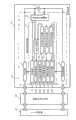
图1是本发明的第一实施例所涉及的脉冲充电控制装置的概略结构图。FIG. 1 is a schematic configuration diagram of a pulse charging control device according to a first embodiment of the present invention.
图2是本发明的第一实施例所涉及的脉冲充电控制装置的详细的方框图。FIG. 2 is a detailed block diagram of the pulse charging control device according to the first embodiment of the present invention.
图3是用以说明本发明的第一实施例所涉及的脉冲充电控制装置的充电动作的流程图。FIG. 3 is a flowchart for explaining the charging operation of the pulse charging control device according to the first embodiment of the present invention.
图4是本发明的第二实施例所涉及的脉冲充电控制装置的详细的方框图。4 is a detailed block diagram of a pulse charging control device according to a second embodiment of the present invention.
图5是用以说明本发明的第二实施例所涉及的脉冲充电控制装置的充电动作的流程图。FIG. 5 is a flowchart for explaining the charging operation of the pulse charging control device according to the second embodiment of the present invention.
具体实施方式Detailed ways
本发明是一种用于便携式电子设备的非水电解质二次电池的脉冲充电方法,以测量脉冲充电的脉冲持续时的电池电压,比较所测量出的电池电压和指定的设定电压,当测量出的电池电压达到指定的设定电压以上时结束脉冲充电为特征,据此起到可同时实现脉冲充电时间的缩短和防止电池劣化的效果。The invention is a pulse charging method for a non-aqueous electrolyte secondary battery used in portable electronic equipment. It measures the battery voltage when the pulse of pulse charging lasts, compares the measured battery voltage with the specified set voltage, and when measured It is characterized by the end of pulse charging when the output battery voltage reaches the specified set voltage or higher, thereby achieving the effect of shortening the pulse charging time and preventing battery deterioration at the same time.
此外,也可基于电池温度来设定所述指定的设定电压。即,由于导致电池劣化的电压具有温度依存性,所以通过设定基于电池温度的指定的设定电压,在不让劣化的情况下,可有效地将最大的电量充电到电池中。In addition, the specified set voltage may also be set based on the battery temperature. That is, since the voltage that causes battery deterioration has temperature dependence, by setting a specified set voltage based on the battery temperature, the battery can be efficiently charged with the maximum amount of power without deterioration.
另外,也可将所述指定的设定电压设定为4.2V以上。据此,可在抑制非水电解质二次电池的金属析出的同时提高充电的效率。In addition, the specified set voltage may be set to 4.2V or higher. Accordingly, the efficiency of charging can be improved while suppressing metal deposition in the non-aqueous electrolyte secondary battery.
下面,利用附图对本发明的实施例进行说明。Next, embodiments of the present invention will be described with reference to the drawings.
(第一实施例)(first embodiment)
图1是表示包含采用本发明所涉及的脉冲充电方法的脉冲充电控制装置的电池组件10的概略结构的一例的方框图。在图1中,在电池组件10内的脉冲充电控制装置11实施充电。图1中的AC适配器30作为充电用电源具有稳定的特性,并具有以恒流供给充电电流ICHG的能力。FIG. 1 is a block diagram showing an example of a schematic configuration of a
脉冲充电控制装置11上连接有非水电解质二次电池3。作为非水电解质二次电池3,可采用例如锂离子二次电池等各种非水电解质二次电池。The non-aqueous electrolyte
AC适配器30与便携式电子设备20连接,便携式电子设备20与电池组件10连接。便携式电子设备20为便携式个人电脑或数码相机、移动电话机等由电池驱动的各种电子设备。The
而且,由从AC适配器30输出的电压,在例如便携式电子设备20内的恒流电路中生成一定的充电电流ICHG,并经由便携式电子设备20供给到电池组件10内的脉冲充电控制装置11,在脉冲充电控制装置11成为脉冲状后供给到非水电解质二次电池3,据此非水电解质二次电池3被脉冲充电。Furthermore, a constant charging current ICHG is generated in, for example, a constant current circuit in the portable
图2是本发明的第一实施例所涉及的脉冲充电控制装置的详细的方框图。图1中的脉冲充电控制装置11在图2中包括:接通/断开充电电流的开关部1;检测电池电压的电池电压检测部2;根据充电电流来检测AC适配器30的连接情况的电流检测部4;以及进行脉冲充电的整体控制的脉冲充电控制部5。进一步,脉冲充电控制部5包括:对后述的各部分进行控制的控制部51;基于控制部51的控制,生成指定的设定电压来作为基准电压的指定的设定电压生成部52(设定电压设定部);规定充电周期的周期计时设定部53;设定由规定的充电周期与占空(duty)比的积所决定的占空时间的占空计时设定部54(占空比设定部);以及对指定的设定电压生成部52所生成的指定的设定电压V1和从所述电池电压检测部2得到的电池电压进行电压比较的电压比较部55,这些各部分可通过微电脑来实现。FIG. 2 is a detailed block diagram of the pulse charging control device according to the first embodiment of the present invention. The pulse
具体而言,开关部1也可采用例如对非水电解质二次电池3的充电方向的电流进行开闭的充电开关和对非水电解质二次电池3的放电方向的电流进行开闭的放电开关的结构。作为开关部1(充电开关、放电开关),可采用例如FET(Field Effect Transistor,场效应晶体管)等半导体开关元件。Specifically, the
电压比较部55采用例如比较器(comparator)来构成。设定电压生成部52采用例如输出设定电压V1的恒压电路或数字模拟转换器的结构。而且,设定电压生成部52例如将非水电解质二次电池3的满充电电压即4.2V作为设定电压输出到电压比较部55。另外,例如通过微电脑执行指定的控制程序,作为周期计时设定部53以及占空计时设定部54而发挥功能。The
另外,控制部51例如通过微电脑执行指定的控制程序,作为充电控制部511、充电结束控制部512以及平均值算出部513而发挥功能。另外,控制部51包括对充电脉冲的周期进行计时的计时电路即周期计时器515以及对充电脉冲的导通时间进行计时的计时电路即占空计时器516。In addition,
充电控制部511根据周期计时器515以及占空计时器516的计时时间来接通、断开开关部1,以此向非水电解质二次电池3以脉冲状周期性地供给电流,从而进行脉冲充电。The
另外,充电结束控制部512,在电压比较部55的比较结果,由电池电压检测部2所测量出的电池电压达到从设定电压生成部52输出的设定电压V1以上时,例如断开开关部1以结束脉冲充电。In addition, when the battery voltage measured by the battery
另外,平均值算出部513算出在由周期计时器515计时的一个周期的期间中,由电池电压检测部2所测量出的电池电压的平均值VAVE。In addition, the average
另外,占空计时设定部54,按照充电脉冲的各周期,每当由平均值算出部513算出的平均值VAVE超过指定的充电控制电压VC时,将脉冲充电的脉冲的导通占空比的值减少预先设定的值,例如1%,并将此占空比与充电周期的积作为占空时间而设定在占空计时器516中。In addition, the duty
另外,占空计时设定部54按照充电脉冲的各个周期,当由平均值算出部513算出的平均值VAVE低于充电控制电压VC时,将脉冲充电的脉冲的导通占空比的值增加预先设定的值,例如1%,并将此占空比与充电周期的积作为占空时间而设定在占空计时器516中。In addition, the duty
充电控制电压VC,在例如设非水二次电池(即,非水电解质二次电池)3达到满充电时的开路电压为Voc、非水二次电池3在正常状态下的内阻值为r、结束脉冲充电时的充电脉冲的一个周期中的充电电流的平均值为α时,基于下述公式(1)而求得。Charging control voltage VC , for example, if the open circuit voltage of the non-aqueous secondary battery (that is, non-aqueous electrolyte secondary battery) 3 reaches full charge is Voc, and the internal resistance of the non-aqueous
VC=Voc+r×α……(1)VC =Voc+r×α...(1)
在此,所谓正常状态是指适合于使用非水二次电池3的状态,作为内阻值r,例如可设定为非水二次电池3适合于使用的内阻值的范围的上限值。另外,电流值α,例如,当设可使满充电状态的非水二次电池3在1小时内放电到蓄电量达到零的电流值为1It时,可采用0.1It左右的电流值。Here, the so-called normal state refers to a state suitable for use of the non-aqueous
例如,如果进行脉冲充电时的占空比的最小值(如果充电脉冲的占空比变得比此值更小则应停止脉冲充电的占空比)为d(%),则电流值α为(d/100)×ICHG。For example, if the minimum value of the duty ratio at the time of pulse charging (the duty ratio at which pulse charging should be stopped if the duty ratio of the charging pulse becomes smaller than this value) is d (%), the current value α is (d/100)×ICHG .
在此,对与平均值VAVE的关系进行说明。当设满充电时充电脉冲持续时的充电电压VB为电压Vf时,满充电时的平均值VAVE可基于下公式求得。Here, the relationship with the average value VAVE will be described. Assuming that the charging voltage VB when the charging pulse continues during full charging is the voltageVf , the average value VAVE at full charging can be obtained based on the following formula.
VAVE=(d/100)×Vf+(1-d/100)+VocVAVE =(d/100)×Vf +(1-d/100)+Voc
=(d/100)×(Voc+r×ICHG)+(1-d/100)+Voc=(d/100)×(Voc+r×ICHG )+(1-d/100)+Voc
=Voc+(d/100)×r×ICHG ……(2)=Voc+(d/100)×r×ICHG ... (2)
在此,根据公式(1),Here, according to formula (1),
VC=Voc+r×αVC =Voc+r×α
=Voc+r×(d/100)×ICHG,因此VC=VAVE。=Voc+r×(d/100)×ICHG , so VC =VAVE .
即,充电控制电压VC表示非水电解质二次电池3达到满充电时的平均值VAVE。That is, the charging control voltage VC represents the average value VAVE when the non-aqueous electrolyte
图3是用于说明本发明的第一实施例所涉及的脉冲充电控制装置11的充电动作的流程图。在步骤S101指示充电开始后,在步骤S102,通过占空计时设定部54,脉冲的导通占空比D在开始时刻被设定为100%。接着,在步骤S103,通过周期计时设定部53设定周期T来作为周期计时器515的计时值,而且通过占空计时设定部54设定T×D/100来作为占空计时器516的计时值。此外,作为周期T而言,选择50msec至2sec中的适当值为佳。因此,例如,如果周期T为50msec,则脉冲的导通占空比D为100%,因此占空计时被设定为50msec×100/100=50msec。FIG. 3 is a flowchart for explaining the charging operation of the pulse charging
如上所述,如果计时值被设定,则开始周期计时器515及占空计时器516的计时。As described above, when the count value is set, the
在步骤S104,由控制部51(充电控制部511)将开关部1的充电开关设置为接通。在步骤S115,由电池电压检测部2测量充电中的非水电解质二次电池3的电压VB。在步骤S116,由电压比较部55判定非水电解质二次电池3的充电电压(端子电压)VB是否为指定的设定电压V1以下。此判定通过电压比较部55对电池电压检测部2所检测出的非水电解质二次电池3的充电电压VB和在指定的设定电压生成部52所设定的指定的设定电压V1进行电压比较而实现。如果充电电压VB为设定电压V1以上,则前进到步骤S126,由充电结束控制部512将开关部1的充电开关设置为断开后充电结束,另外,如果充电电压VB低于设定电压V1,则前进到步骤S117。In step S104, the charging switch of the
在步骤S117,由控制部51(充电控制部511)判定占空计时器516的计时值是否超过T×D/100。如果占空计时器516的计时值未超过T×D/100,则再次返回到步骤S115。另外,如果占空计时器516的计时值超过T×D/100,则前进到步骤S118。在步骤S118,由控制部51(充电控制部511)判定周期计时器515的计时值是否超过周期T。如果周期计时器515的计时值未超过周期T,则前进到步骤S119。另外,如果被设定的周期计时器515的计时值超过周期T,则前进到步骤S121。In step S117, it is determined by the control unit 51 (charging control unit 511) whether or not the counted value of the
在步骤S119,由控制部51(充电控制部511)将开关部1的充电开关设置为断开。在步骤S120,重复步骤S120至周期计时器515的计时值超过周期T为止,如果周期计时器515的计时值超过所设定的周期T,则前进到步骤S121。In step S119, the charging switch of the
以上,通过步骤S103至S120的处理,以周期T、导通占空比D的脉冲电流执行脉冲充电。As above, through the processing of steps S103 to S120 , pulse charging is performed with a pulse current having a period T and a conduction duty ratio D. FIG.
另一方面,由控制部51(平均值算出部513),算出在周期T内由电池电压检测部2所测量出的非水电解质二次电池3的电压的平均值VAVE。而且,在步骤S121,由占空计时设定部54比较判定平均值VAVE(应为VAVE)和充电控制电压VC的大小。判定的结果,如果VAVE大于VC(应为大于等于VC),则转移到步骤S122,在此,由占空计时设定部54递减(decrement)(减少)脉冲的导通占空比D后,前进到步骤S125。另外,判定的结果,如果VAVE小于VC,则转移到步骤S123。On the other hand, the average value VAVE of the voltage of the non-aqueous electrolyte
在步骤S123,由占空计时设定部54判定脉冲的导通占空比D是否为100%。如果导通占空比D为100%则前进到步骤S125。另外,如果导通占空比D不为100%则前进到步骤S124,在此,由占空计时设定部54递增(increment)(增加)脉冲的导通占空比D后,前进到步骤S125。In step S123, it is determined by the duty
在此,如果导通占空比D减少则平均值VAVE会降低,而如果导通占空比D增加则平均值VAVE会上升,因此通过步骤S121至S124的处理,来调节导通占空比D,以使充电脉冲的一个周期中的平均值VAVE接近并大致等于充电控制电压VC。Here, if the on-duty ratio D decreases, the average value VAVE will decrease, and if the on-duty ratio D increases, the average value VAVE will rise, so the on-duty ratio is adjusted through the processing of steps S121 to S124. Duty ratio D, so that the average value VAVE in one cycle of the charging pulse is close to and roughly equal to the charging control voltage VC .
而且,充电控制电压VC以上述公式(1)来表示。在此,公式(1)中的r×α项相当于在脉冲充电结束时因非水二次电池(即,非水电解质二次电池)3的内阻所引起的电压下降,所以此电压下降与满充电时的开路电压Voc相加所得的充电控制电压VC相当于在脉冲充电结束时的非水二次电池3的端子电压,并且相当于在不使非水二次电池3达到过电压的范围内可充电的上限电压。Furthermore, the charging control voltage VC is represented by the above formula (1). Here, the r×α term in the formula (1) corresponds to the voltage drop caused by the internal resistance of the nonaqueous secondary battery (ie, nonaqueous electrolyte secondary battery) 3 at the end of the pulse charging, so this voltage drop The charging control voltage VC obtained by adding the open-circuit voltage Voc at the time of full charge is equivalent to the terminal voltage of the non-aqueous
因此,通过逐渐减少导通占空比D,以使充电脉冲的一个周期中的平均值VAVE等于充电控制电压VC,从而可将一个周期中的平均值VAVE作为在不让非水二次电池3达到过电压的范围内可充电的上限电压即充电控制电压VC,其结果,可有效率地对非水二次电池3进行充电。Therefore, by gradually reducing the conduction duty ratio D, the average value VAVE in one cycle of the charging pulse is equal to the charging control voltage VC , so that the average value VAVE in one cycle can be used as the The
在步骤S125,由控制部51(充电结束控制部512)判定脉冲的导通占空比D是否低于规定值d(此处为10%)。判定的结果,如果脉冲的导通占空比D低于规定值d,则结束充电。但是,判定的结果,如果脉冲的导通占空比D并不低于规定值d,则返回到步骤S103。In step S125, it is determined by the control unit 51 (charging end control unit 512) whether or not the on-duty ratio D of the pulse is lower than a predetermined value d (here, 10%). As a result of the determination, if the on-duty ratio D of the pulse is lower than the predetermined value d, charging is terminated. However, as a result of the determination, if the on-duty ratio D of the pulse is not lower than the predetermined value d, the process returns to step S103.
如上所述地通过本发明的第一实施例所涉及的脉冲充电控制装置11来开始、结束非水电解质二次电池3的充电。充电刚开始时,脉冲的导通占空比D以100%推移,从而实质上进行恒流充电。从刚检测出非水电解质二次电池3的电池电压的平均值VAVE为充电控制电压VC以上的情况之后周期T起,开始递减导通占空比D。当电池不劣化、导通占空时的电压未达到指定的电压V1以上时,在通过导通占空比D的递减而导通占空比D低于规定值d(此处为10%)的时刻结束充电。另一方面,在电池劣化而导通占空时的电压达到指定的电压V1以上时,在此时刻结束充电。Charging of the non-aqueous electrolyte
从导通占空比D开始递减至因导通占空比D的递减而导通占空比D低于规定值d(此处为10%)的时刻为止,实质上进行脉冲充电。但是,重要的是要认识到,本发明的第一实施例的充电动作从充电开始起始终为脉冲充电方式。而且,虽然在所述实施例中导通占空比D的递减或递增量为1%,但不用多说,此值也可以任意设定。Pulse charging is substantially performed from the on-duty ratio D starting to decrease until the on-duty ratio D falls below a predetermined value d (here, 10%) due to the decrement of the on-duty ratio D. However, it is important to realize that the charging operation of the first embodiment of the present invention is always a pulse charging method from the beginning of charging. Moreover, although the decrement or incremental amount of the conduction duty ratio D is 1% in the described embodiment, it goes without saying that this value can also be set arbitrarily.
以上,根据步骤S121至S125的处理,即便在步骤S116非水电解质二次电池3的充电电压VB未超过设定电压V1即满充电电压,也能结束脉冲充电,因此可减轻非水电解质二次电池3被施加过电压而劣化的危险。Above, according to the processing of steps S121 to S125, even if the charging voltage VB of the nonaqueous electrolyte
另外,所述实施例中判定充电结束的规定值d也被设定为10%,但此值也可任意设定。In addition, in the above-described embodiment, the predetermined value d for determining the end of charging is also set at 10%, but this value may be set arbitrarily.
此外,图1及图2中,示出了在电池组件中具有脉冲充电控制装置的例子,但不用多说,也可在电池组件之外、例如移动电话等便携式电子设备中具有脉冲充电控制装置。In addition, in Fig. 1 and Fig. 2, an example of having a pulse charging control device in the battery pack is shown, but needless to say, the pulse charging control device may also be provided in a portable electronic device such as a mobile phone outside the battery pack .
(第二实施例)(second embodiment)
图4是本发明的第二实施例的脉冲充电控制装置的详细的方框图。图1中的脉冲充电控制装置11在图4中包括:接通/断开充电电流的开关部1;检测电池电压的电池电压检测部2;根据充电电流来检测AC适配器30的连接情况的电流检测部4;检测电池温度的电池温度检测部6;以及进行脉冲充电的整体控制的脉冲充电控制部5。进一步,脉冲充电控制部5包括:对后述的各部分进行控制的控制部51;基于控制部51的控制,生成指定的设定电压来作为基准电压的指定的设定电压生成部52(设定电压设定部);规定充电周期的周期计时设定部53;设定由规定的充电周期与占空比的积所决定的占空时间的占空计时设定部54(占空比设定部);以及对指定的设定电压生成部52的指定的设定电压V1和由所述电池电压检测部2得到的电池电压进行电压比较的电压比较部55,这些各部分可通过微电脑来实现。Fig. 4 is a detailed block diagram of a pulse charging control device according to a second embodiment of the present invention. The pulse
图4所示的脉冲充电控制装置11与图2所示的脉冲充电控制装置11的不同点在于,还包括电池温度检测部6,以及设定电压生成部52的动作。其他方面与图2所示的脉冲充电控制装置11相同,因此省略说明。The difference between the pulse charging
电池温度检测部6检测非水电解质二次电池3的温度,并将表示此温度的信号输出到控制部51。控制部51将表示由电池温度检测部6得到的非水电解质二次电池3的温度的信息输出到设定电压生成部52。The battery
设定电压生成部52采用例如微电脑与数字模拟转换器的结构。而且,设定电压生成部52将设定电压V1设定成:电池温度检测部6所检测出的温度越高,则设定电压V1越低,并且将此设定电压V1输出到电压比较部55。The set
图5是用于说明本发明的第二实施例所涉及的脉冲充电控制装置11的充电动作的流程图。在步骤S201指示充电开始后,在步骤S202,通过占空计时设定部54,脉冲的导通占空比D在开始时刻被设定为100%。接着,在步骤S203,由周期计时设定部53设定周期T来作为周期计时器515的计时值,而且由占空计时设定部54设定T×D/100来作为占空计时器516的计时值。此外,作为周期T而言,选择50msec至2sec中的适当值为佳。因此,例如,如果周期T为50msec,则脉冲的导通占空比D为100%,因此占空计时器被设定为50msec×100/100=50msec。FIG. 5 is a flowchart for explaining the charging operation of the pulse charging
如上所述,当计时值被设定时,周期计时器515及占空计时器516的计时开始。As described above, when the count value is set, counting by the
在步骤S204,由控制部51(充电控制部511)将开关部1的充电开关设置为接通。在步骤S213,由电池温度检测部6测量非水电解质二次电池3的电池温度并传送到控制部51。在步骤S214,由设定电压生成部52基于电池温度检测部6所测量出的电池温度来设定指定的设定电压V1,并将此设定电压V1输出到电压比较部55。在步骤S215,由电池电压检测部2测量充电中的非水电解质二次电池3的电压VB。在步骤S216,由电压比较部55判定非水电解质二次电池3的充电电压VB是否为指定的设定电压V1以下(应为是否小于指定的设定电压V1)。此判定通过电压比较部55对电池电压检测部2所检测出的非水电解质二次电池3的充电电压VB和指定的设定电压生成部52所设定的指定的设定电压V1进行电压比较而实现。如果充电电压VB为设定电压V1以上,则前进到步骤S226,由充电结束控制部512将开关部1的充电开关设置为断开后充电结束,另外,如果充电电压VB低于设定电压V1,则前进到步骤S217。In step S204, the charging switch of the
在此,非水电解质二次电池3的温度越高,金属元素开始从非水电解质二次电池3的正极向电解质析出的析出电压则越降低。而且,为了防止正极合剂中的金属的析出,必须将设定电压V1设定为析出电压以下。Here, the higher the temperature of the nonaqueous electrolyte
然而,在图2所示的脉冲充电控制装置11中,当将设定电压V1设定为例如低温时的析出电压以下时,在高温时析出电压变得低于设定电压V1,因此存在在图3所示的步骤S116停止充电之前,正极合剂中的金属就开始析出的可能性。However, in the pulse
另一方面,当将设定电压V1设定为例如高温时的析出电压以下时,有如下顾虑,即在低温时,在距正极合剂中的金属开始析出尚有余裕的状态下,在步骤S116停止充电,因此,存在无法获得本来能获得的蓄电量的可能性。On the other hand, if the set voltage V1 is set below the precipitation voltage at high temperature, for example, there is a concern that at low temperature, there is still room for the metal in the positive electrode mixture to start to precipitate. Charging is stopped, so there is a possibility that the stored amount that could have been obtained may not be obtained.
然而,图4所示的脉冲充电控制装置11,在图5的步骤S214,由设定电压生成部52以电池温度检测部6所测量出的电池温度越高则设定电压V1越低的方式,对设定电压V1进行设定,并将此设定电压V1输出到电压比较部55来与充电电压VB进行比较,因此减轻了在低温时无法获得本来能够获得的蓄电量之虞,并且减轻了在高温时非水电解质二次电池3的正极合剂中的金属析出之虞。However, in the pulse
在步骤S217,由控制部51(充电控制部511)判定占空计时器516的计时值是否超过T×D/100。如果占空计时器516的计时值未超过T×D/100,则再次返回到步骤S213。另外,如果占空计时器516的计时值超过T×D/100,则前进到步骤S218。在步骤S218,由控制部51(充电控制部511)判定周期计时器515的计时值是否超过周期T。如果周期计时器515的计时值未超过周期T,则前进到步骤S219。另外,如果被设定的周期计时器515的计时值超过周期T,则前进到步骤S221。In step S217, it is determined by the control unit 51 (charging control unit 511) whether or not the counted value of the
在步骤S219,由控制部51(充电控制部511)将开关部1的充电开关设置为断开。在步骤S220,重复步骤S220直到周期计时器515的计时值超过周期T为止,如果周期计时器515的计时值超过所设定的周期T,则前进到步骤S221。In step S219, the charging switch of the
以上,通过步骤S203至S220的处理,以周期T、导通占空比D的脉冲电流执行脉冲充电。As above, through the processing of steps S203 to S220 , pulse charging is performed with a pulse current having a period T and a conduction duty ratio D. FIG.
另一方面,由控制部51(平均值算出部513),算出在整个周期T内由电池电压检测部2所测量出的非水电解质二次电池3的电压的平均值VAVE。而且,在步骤S221,由占空计时设定部54比较判定平均值VAVE和充电控制电压VC的大小。判定的结果,如果VAVE大于VC,则转移到步骤S222,在此,由占空计时设定部54递减(减少)脉冲的导通占空比D后,前进到步骤S225。另外,判定的结果,如果VAVE小于VC,则转移到步骤S223。On the other hand, the average value VAVE of the voltage of the nonaqueous electrolyte
在步骤S223,由占空计时设定部54判定脉冲的导通占空比D是否为100%。如果导通占空比D为100%则前进到步骤S225。另外,如果导通占空比D不为100%则前进到步骤S224,在此,由占空计时设定部54递增(增加)脉冲的导通占空比D后,前进到步骤S225。In step S223, it is determined by the duty
在步骤S225,由控制部51(充电结束控制部512)判定脉冲的导通占空比D是否低于规定值d(此处为10%)。判定的结果,如果脉冲的导通占空比D低于规定值d则结束充电。但是,判定的结果,如果脉冲的导通占空比D并不低于规定值d,则返回到步骤S203。In step S225, it is determined by the control unit 51 (charging end control unit 512) whether or not the on-duty ratio D of the pulse is lower than a predetermined value d (here, 10%). As a result of the determination, if the on-duty ratio D of the pulse is lower than the predetermined value d, charging is terminated. However, as a result of the determination, if the on-duty ratio D of the pulse is not lower than the predetermined value d, the process returns to step S203.
如上所述,通过本发明的第二实施例所涉及的脉冲充电控制装置11来开始、结束非水电解质二次电池3的充电。As described above, charging of the nonaqueous electrolyte
即,本发明所涉及的非水电解质二次电池的脉冲充电方法包括:通过向非水电解质二次电池以脉冲状周期性地供给电流来进行脉冲充电的充电控制工序;测量所述非水电解质二次电池的电池电压的电池电压检测工序;比较通过所述电池电压检测工序在以所述脉冲状供给电流时所测量的电池电压和指定的设定电压的比较工序;以及当所述比较的结果,所述测量出的电池电压达到所述设定电压以上时,结束所述脉冲充电的充电结束控制工序。That is, the pulse charging method of the non-aqueous electrolyte secondary battery involved in the present invention includes: a charge control process for pulse charging by periodically supplying current in a pulse form to the non-aqueous electrolyte secondary battery; measuring the non-aqueous electrolyte a battery voltage detection process of a battery voltage of a secondary battery; a comparison process of comparing a battery voltage measured by the battery voltage detection process when a current is supplied in the pulse form with a specified set voltage; and when the compared As a result, when the measured battery voltage becomes equal to or higher than the set voltage, the charge completion control step of the pulse charging is terminated.
另外,本发明所涉及的脉冲充电控制装置包括:通过向非水电解质二次电池以脉冲状周期性地供给电流来进行脉冲充电的充电控制部;测量所述非水电解质二次电池的电池电压的电池电压检测部;比较通过所述电池电压检测部在以所述脉冲状供给电流时所测量出的电池电压和指定的设定电压的电压比较部;以及当所述电压比较部的比较结果,所述测量出的电池电压达到所述设定电压以上时,结束所述脉冲充电的充电结束控制部。In addition, the pulse charge control device according to the present invention includes: a charge control unit that performs pulse charge by periodically supplying current in a pulse form to the nonaqueous electrolyte secondary battery; and measures the battery voltage of the nonaqueous electrolyte secondary battery. a battery voltage detection section; a voltage comparison section that compares the battery voltage measured by the battery voltage detection section when the current is supplied in the pulse form with a specified set voltage; and when the comparison result of the voltage comparison section A charge termination control unit for terminating the pulse charging when the measured battery voltage reaches the set voltage or higher.
根据所述结构,在脉冲充电时,当电流被供给到非水电解质二次电池时的电池电压达到设定电压以上时,结束脉冲充电以防止电池电压的进一步上升,因此即便在充电电流流过非水电解质二次电池的内阻而导致电池电压上升的状态下,也能将电池电压抑制在设定电压以下。因此,通过将设定电压设定为正极合剂中的金属析出的析出电压以下,可容易地抑制正极合剂中的金属的析出及伴随此析出的电池特性的降低。According to the above structure, when the battery voltage when the current is supplied to the non-aqueous electrolyte secondary battery reaches the set voltage or more during the pulse charging, the pulse charging is terminated to prevent further rise of the battery voltage, so even when the charging current flows Even when the battery voltage rises due to the internal resistance of the non-aqueous electrolyte secondary battery, the battery voltage can be suppressed below the set voltage. Therefore, by setting the set voltage to be equal to or lower than the precipitation voltage at which metals in the positive electrode mixture are deposited, it is possible to easily suppress the precipitation of metals in the positive electrode mixture and the decrease in battery characteristics associated with the precipitation.
另外,较为理想的是,上述的非水电解质二次电池的脉冲充电方法还包括:检测所述非水二次电池的温度的电池温度检测工序;以及基于在所述电池温度检测工序检测出的温度来设定所述设定电压的设定电压设定工序。In addition, it is more desirable that the above-mentioned pulse charging method for a non-aqueous electrolyte secondary battery further includes: a battery temperature detection process for detecting the temperature of the non-aqueous secondary battery; and based on the temperature detected in the battery temperature detection process temperature to set the set voltage setting process of the set voltage.
另外,较为理想的是,上述的脉冲充电控制装置还包括:检测所述非水二次电池的温度的电池温度检测部;以及基于由所述电池温度检测部检测出的温度来设定所述设定电压的设定电压设定部。In addition, preferably, the above-mentioned pulse charging control device further includes: a battery temperature detection unit that detects the temperature of the non-aqueous secondary battery; and setting the battery temperature based on the temperature detected by the battery temperature detection unit. Set voltage setting section for setting voltage.
非水电解质二次电池的析出电压依存于温度而变化。在此,基于非水二次电池的温度,将设定电压设定为与此温度相对应的析出电压以下的电压,从而不管非水二次电池的温度如何,均可容易地抑制正极合剂中的金属的析出及伴随此析出的电池特性的降低。The deposition voltage of the non-aqueous electrolyte secondary battery changes depending on the temperature. Here, based on the temperature of the non-aqueous secondary battery, the set voltage is set to a voltage below the precipitation voltage corresponding to the temperature, so that no matter what the temperature of the non-aqueous secondary battery is, it is easy to suppress the formation of the positive electrode mixture. The precipitation of metals and the reduction of battery characteristics associated with this precipitation.
另外,较为理想的是,上述的非水电解质二次电池的脉冲充电方法在所述设定电压设定工序,设定所述设定电压使所述设定电压随在所述电池温度检测工序检测出的温度的提高而降低。In addition, it is more desirable that, in the above-mentioned pulse charging method for non-aqueous electrolyte secondary batteries, in the step of setting the set voltage, the set voltage is set such that the set voltage follows the temperature of the battery temperature in the step of detecting the battery temperature. decrease with an increase in the detected temperature.
另外,较为理想的是,在上述的脉冲充电控制装置中,所述设定电压设定部,设定所述设定电压使所述设定电压随由所述电池温度检测部检测出的温度的提高而降低。In addition, preferably, in the above pulse charging control device, the set voltage setting unit sets the set voltage such that the set voltage follows the temperature detected by the battery temperature detecting unit. increase and decrease.
温度越高,非水电解质二次电池的析出电压就降得越低。由此,根据所述结构,以非水电解质二次电池的温度越高则设定电压越低的方式来设定该设定电压,因此可根据非水二次电池的温度来设定能够抑制正极合剂中的金属的析出的设定电压。另外,在预先设定有与高温时的析出电压相对应的设定电压时,会有设定电压被设定得过低而导致充电不充分的顾虑,但根据所述结构,在低温时可使设定电压上升,因此减轻了充电不充分的顾虑。The higher the temperature, the lower the precipitation voltage of the non-aqueous electrolyte secondary battery. Thus, according to the above configuration, the set voltage is set in such a manner that the higher the temperature of the nonaqueous electrolyte secondary battery is, the lower the set voltage is, so it can be set according to the temperature of the nonaqueous electrolyte secondary battery. The set voltage for the precipitation of metals in the positive electrode mixture. In addition, when the set voltage corresponding to the deposition voltage at high temperature is preset, there is a possibility that the set voltage is set too low, resulting in insufficient charging. However, according to the above structure, it is possible to Since the set voltage is increased, concerns about insufficient charging are alleviated.
另外,所述设定电压也可为4.2V以上。In addition, the set voltage may be greater than or equal to 4.2V.
4.2V是非水电解质二次电池的通常的析出电压,因此适于作为设定电压。Since 4.2 V is a normal deposition voltage of a non-aqueous electrolyte secondary battery, it is suitable as a set voltage.
另外,较为理想的是,上述的非水电解质二次电池的脉冲充电方法还包括:算出所述周期中的一个周期的所述电池电压的平均值的平均值算出工序;以及每当所述平均值超过指定的充电控制电压时,使所述脉冲充电的脉冲的导通占空比减少预先设定的值的占空比设定工序,其中,在所述充电结束控制工序,当在所述占空比设定工序所设定的占空比低于预先设定的规定值时,结束所述脉冲充电。In addition, it is more desirable that the above-mentioned pulse charging method for a non-aqueous electrolyte secondary battery further includes: calculating an average value calculation process of the average value of the battery voltage in one cycle in the cycle; A duty ratio setting step of reducing the on-duty ratio of the pulse charging pulse by a preset value when the value exceeds the specified charging control voltage, wherein, in the charging end control step, when the When the duty ratio set in the duty ratio setting step is lower than a predetermined value set in advance, the pulse charging is terminated.
另外,较为理想的是,在上述的脉冲充电控制装置中还包括:算出在所述周期中的一个周期由所述电池电压检测部测量的电池电压的平均值的平均值算出部;以及每当所述平均值超过指定的充电控制电压时,使所述脉冲充电的脉冲的导通占空比减少预先设定的值的占空比设定部,其中,所述充电结束控制部,当由所述占空比设定部所设定的占空比低于预先设定的规定值时,结束所述充电控制部的脉冲充电。In addition, preferably, the above-mentioned pulse charging control device further includes: an average value calculation unit that calculates an average value of the battery voltage measured by the battery voltage detection unit in one cycle of the cycle; a duty ratio setting section that reduces the on-duty ratio of the pulse charging pulse by a preset value when the average value exceeds a specified charging control voltage, wherein the charging end control section is configured to When the duty ratio set by the duty ratio setting unit is lower than a predetermined value set in advance, the pulse charging by the charging control unit is terminated.
根据所述结构,即便非水电解质二次电池的电池电压未达到设定电压以上,也可结束脉冲充电,因此可减轻非水电解质二次电池被施加过电压而劣化的顾虑。According to the above configuration, pulse charging can be terminated even if the battery voltage of the nonaqueous electrolyte secondary battery does not reach the set voltage or higher, so that the nonaqueous electrolyte secondary battery can be less likely to be deteriorated due to overvoltage.
另外,较为理想的是,上述的非水电解质二次电池的脉冲充电方法在所述占空比设定工序,当所述平均值低于所述充电控制电压时,使所述脉冲充电的脉冲的导通占空比增加预先设定的值。In addition, it is more desirable that, in the above-mentioned pulse charging method for non-aqueous electrolyte secondary batteries, in the step of setting the duty ratio, when the average value is lower than the charging control voltage, the pulse of the pulse charging The on-duty cycle increases by a preset value.
另外,较为理想的是,在上述的脉冲充电控制装置中,所述占空比设定部当所述平均值低于所述充电控制电压时,使所述脉冲充电的脉冲的导通占空比增加预先设定的值。In addition, preferably, in the above-mentioned pulse charging control device, the duty ratio setting unit makes the pulse of the pulse charging on-duty when the average value is lower than the charging control voltage. than increase the preset value.
根据所述结构,每当充电脉冲的一个周期中的电池电压的平均值超过充电控制电压时,减少脉冲充电中的脉冲的导通占空比,而在平均值低于充电控制电压时,增加此导通占空比。在此,如果导通占空比减少则平均值降低,而如果导通占空比增加则平均值上升,因此在充电脉冲的一个周期中的平均值接近于充电控制电压的状态下执行脉冲充电。因此,通过适当设定充电控制电压,可容易在适于非水电解质二次电池的充电的条件下进行脉冲充电。According to the above structure, whenever the average value of the battery voltage in one cycle of the charging pulse exceeds the charging control voltage, the on-duty ratio of the pulse in pulse charging is reduced, and when the average value is lower than the charging control voltage, it is increased. This conduction duty cycle. Here, the average value decreases if the on-duty ratio decreases, and the average value increases if the on-duty ratio increases, so pulse charging is performed in a state where the average value in one cycle of the charging pulse is close to the charging control voltage . Therefore, by appropriately setting the charging control voltage, pulse charging can be easily performed under conditions suitable for charging the non-aqueous electrolyte secondary battery.
另外,较为理想的是,当设所述充电控制电压为VC、所述非水二次电池达到满充电时的开路电压为Voc、所述非水二次电池在正常状态下的内阻值为r、结束脉冲充电时的充电脉冲的一个周期的充电电流的平均值为α时,所述充电控制电压基于下述公式(1)而求得,In addition, it is more ideal that when the charging control voltage is VC , the open circuit voltage when the non-aqueous secondary battery is fully charged is Voc, and the internal resistance value of the non-aqueous secondary battery under normal conditions is When r is the average value of the charging current in one cycle of the charging pulse when the pulse charging is completed, the charging control voltage is obtained based on the following formula (1),
VC=Voc+r×α……(1)VC =Voc+r×α...(1)
根据所述结构,公式(1)中的r×α项相当于在脉冲充电结束时因非水二次电池的内阻所引起的电压下降,所以此电压下降与满充电时的开路电压Voc相加所得的充电控制电压VC,相当于在脉冲充电结束时的非水二次电池的端子电压,并且相当于在不让非水二次电池达到过电压的范围内可充电的上限电压。而且,通过逐渐减少导通占空比以使充电脉冲的一个周期中的平均值等于充电控制电压VC,可使一个周期中的平均值为在不让非水二次电池达到过电压的范围内能够充电的上限电压即充电控制电压VC,其结果,可有效率地对非水二次电池进行充电。According to the structure, the r×α term in the formula (1) corresponds to the voltage drop caused by the internal resistance of the non-aqueous secondary battery at the end of the pulse charge, so this voltage drop is equivalent to the open circuit voltage Voc at the time of full charge. The resulting charging control voltage VC corresponds to the terminal voltage of the non-aqueous secondary battery at the end of the pulse charging, and corresponds to the upper limit voltage within which the non-aqueous secondary battery can be charged within the range not to overvoltage. Moreover, by gradually reducing the on-duty ratio so that the average value in one cycle of the charging pulse is equal to the charging control voltage VC , the average value in one cycle can be made within the range that does not allow the non-aqueous secondary battery to reach an overvoltage. The charging control voltage VC is the upper limit voltage that can be charged inside, and as a result, the non-aqueous secondary battery can be charged efficiently.
产业上的可利用性Industrial availability
本发明的非水电解质二次电池的脉冲充电方法以及脉冲充电控制装置,可抑制脉冲充电时的正极合剂中的金属的析出及伴随此析出带来的电池特性的劣化,因此可提高将非水电解质二次电池用作电源的移动电话、笔记本电脑等便携式电子设备的便利性,从而较为有用。The pulse charging method and the pulse charging control device of the non-aqueous electrolyte secondary battery of the present invention can suppress the precipitation of the metal in the positive electrode mixture during pulse charging and the deterioration of the battery characteristics accompanying this precipitation, so the non-aqueous electrolyte can be improved. Electrolyte secondary batteries are useful as a power source for portable electronic devices such as mobile phones and notebook computers due to their convenience.
Claims (14)
Applications Claiming Priority (3)
| Application Number | Priority Date | Filing Date | Title |
|---|---|---|---|
| JP2007-261829 | 2007-10-05 | ||
| JP2007261829 | 2007-10-05 | ||
| PCT/JP2008/002787WO2009044558A1 (en) | 2007-10-05 | 2008-10-03 | Non-aqueous electrolyte secondary cell pulse charge method and pulse charge control device |
Publications (1)
| Publication Number | Publication Date |
|---|---|
| CN101816112Atrue CN101816112A (en) | 2010-08-25 |
Family
ID=40525990
Family Applications (1)
| Application Number | Title | Priority Date | Filing Date |
|---|---|---|---|
| CN200880110521APendingCN101816112A (en) | 2007-10-05 | 2008-10-03 | Pulse charging method for nonaqueous electrolyte secondary battery, and pulse charging control device |
Country Status (5)
| Country | Link |
|---|---|
| US (1) | US20100219795A1 (en) |
| EP (1) | EP2197085A1 (en) |
| JP (1) | JP2009105041A (en) |
| CN (1) | CN101816112A (en) |
| WO (1) | WO2009044558A1 (en) |
Cited By (1)
| Publication number | Priority date | Publication date | Assignee | Title |
|---|---|---|---|---|
| CN104578232A (en)* | 2013-10-29 | 2015-04-29 | 现代自动车株式会社 | Method and apparatus for controlling charge of a low-voltage battery |
Families Citing this family (16)
| Publication number | Priority date | Publication date | Assignee | Title |
|---|---|---|---|---|
| JP5593849B2 (en)* | 2009-06-12 | 2014-09-24 | 日産自動車株式会社 | Battery monitoring device |
| JP2011109833A (en)* | 2009-11-18 | 2011-06-02 | Sony Corp | Method and device for charging secondary battery |
| US10389156B2 (en) | 2010-05-21 | 2019-08-20 | Qnovo Inc. | Method and circuitry to adaptively charge a battery/cell |
| US12081057B2 (en) | 2010-05-21 | 2024-09-03 | Qnovo Inc. | Method and circuitry to adaptively charge a battery/cell |
| US8791669B2 (en) | 2010-06-24 | 2014-07-29 | Qnovo Inc. | Method and circuitry to calculate the state of charge of a battery/cell |
| US10067198B2 (en) | 2010-05-21 | 2018-09-04 | Qnovo Inc. | Method and circuitry to adaptively charge a battery/cell using the state of health thereof |
| US11791647B2 (en) | 2010-05-21 | 2023-10-17 | Qnovo Inc. | Method and circuitry to adaptively charge a battery/cell |
| US11397215B2 (en) | 2010-05-21 | 2022-07-26 | Qnovo Inc. | Battery adaptive charging using battery physical phenomena |
| US11397216B2 (en) | 2010-05-21 | 2022-07-26 | Qnovo Inc. | Battery adaptive charging using a battery model |
| US9142994B2 (en)* | 2012-09-25 | 2015-09-22 | Qnovo, Inc. | Method and circuitry to adaptively charge a battery/cell |
| US9225185B2 (en)* | 2011-10-21 | 2015-12-29 | Samsung Electronics Co., Ltd. | Method and apparatus for controlling charging in electronic device |
| US9146280B2 (en)* | 2011-10-26 | 2015-09-29 | Industrial Technology Research Institute | Method and system for estimating a capacity of a battery |
| US9461492B1 (en) | 2013-04-19 | 2016-10-04 | Qnovo Inc. | Method and circuitry to adaptively charge a battery/cell using a charge-time parameter |
| US10574079B1 (en) | 2014-06-20 | 2020-02-25 | Qnovo Inc. | Wireless charging techniques and circuitry for a battery |
| TWI585429B (en)* | 2015-12-31 | 2017-06-01 | 環旭電子股份有限公司 | Method of estimating battery capacity |
| FR3107145B1 (en)* | 2020-02-06 | 2022-01-14 | Psa Automobiles Sa | IMPULSIVE CHARGING PROCESS IN VOLTAGE REGULATION WITH VARIABLE AMPLITUDE LEVELS |
Family Cites Families (14)
| Publication number | Priority date | Publication date | Assignee | Title |
|---|---|---|---|---|
| US5523671A (en)* | 1991-02-14 | 1996-06-04 | Dell Usa, L.P. | Charging system for battery powered devices |
| JP3005460B2 (en)* | 1995-04-18 | 2000-01-31 | 三洋電機株式会社 | Rechargeable battery charging method |
| US5747969A (en)* | 1995-11-21 | 1998-05-05 | Sanyo Electric Co., Ltd. | Method of charging a rechargeable battery with pulses of a predetermined amount of charge |
| JPH09168240A (en)* | 1995-12-12 | 1997-06-24 | Toyota Motor Corp | Battery charger |
| JP3439029B2 (en)* | 1996-02-29 | 2003-08-25 | 三洋電機株式会社 | Battery device |
| JP3580828B2 (en)* | 1996-05-21 | 2004-10-27 | 松下電器産業株式会社 | Pulse charging method and charging device |
| AUPO917297A0 (en)* | 1997-09-15 | 1997-10-09 | Commonwealth Scientific And Industrial Research Organisation | Charging of batteries |
| GB2330460B (en)* | 1997-10-16 | 2001-09-05 | Nec Technologies | Fast charging of lithium ion cells |
| JP3671891B2 (en)* | 2001-10-04 | 2005-07-13 | オムロン株式会社 | Sensor network system management method, sensor network system management program, recording medium storing sensor network system management program, and sensor network system management apparatus |
| JP3926699B2 (en)* | 2002-07-30 | 2007-06-06 | 株式会社リコー | Secondary battery charging device and charging method thereof |
| US6707272B1 (en)* | 2002-11-22 | 2004-03-16 | Motorola, Inc. | Pulse charging circuit and method |
| JP4429621B2 (en)* | 2003-04-18 | 2010-03-10 | 日本電信電話株式会社 | Charge control method for alkaline aqueous battery |
| JP3925507B2 (en)* | 2004-04-23 | 2007-06-06 | ソニー株式会社 | Secondary battery charging method and battery pack |
| US7382110B2 (en)* | 2004-04-23 | 2008-06-03 | Sony Corporation | Method of charging secondary battery, method of calculating remaining capacity rate of secondary battery, and battery pack |
- 2008
- 2008-10-03USUS12/681,713patent/US20100219795A1/ennot_activeAbandoned
- 2008-10-03CNCN200880110521Apatent/CN101816112A/enactivePending
- 2008-10-03JPJP2008258399Apatent/JP2009105041A/enactivePending
- 2008-10-03EPEP08835926Apatent/EP2197085A1/ennot_activeWithdrawn
- 2008-10-03WOPCT/JP2008/002787patent/WO2009044558A1/enactiveApplication Filing
Cited By (2)
| Publication number | Priority date | Publication date | Assignee | Title |
|---|---|---|---|---|
| CN104578232A (en)* | 2013-10-29 | 2015-04-29 | 现代自动车株式会社 | Method and apparatus for controlling charge of a low-voltage battery |
| CN104578232B (en)* | 2013-10-29 | 2018-05-29 | 现代自动车株式会社 | The method and apparatus that low-voltage battery is controlled to charge |
Also Published As
| Publication number | Publication date |
|---|---|
| WO2009044558A1 (en) | 2009-04-09 |
| US20100219795A1 (en) | 2010-09-02 |
| EP2197085A1 (en) | 2010-06-16 |
| JP2009105041A (en) | 2009-05-14 |
Similar Documents
| Publication | Publication Date | Title |
|---|---|---|
| CN101816112A (en) | Pulse charging method for nonaqueous electrolyte secondary battery, and pulse charging control device | |
| US6456042B1 (en) | Method and apparatus for charging batteries at reduced overcharge levels | |
| CN101816092B (en) | Secondary cell charge control method and charge control circuit | |
| JP5839210B2 (en) | Battery charging apparatus and method | |
| JP7275452B2 (en) | SECONDARY BATTERY OPERATION CONTROL DEVICE AND METHOD USING RELATIVE DEGREE OF ELECTRODE | |
| US6137265A (en) | Adaptive fast charging of lithium-ion batteries | |
| JP5410248B2 (en) | Charging system that guarantees the lifetime of secondary batteries | |
| JP3580828B2 (en) | Pulse charging method and charging device | |
| JP3823503B2 (en) | Secondary battery charging control method and charging device therefor | |
| JP3216133B2 (en) | Non-aqueous electrolyte secondary battery charging method | |
| CN1230798A (en) | Method for managing charge/discharge of secondary battery | |
| CN101523659A (en) | Discharge controller | |
| JP5636535B2 (en) | Charging / discharging device and method for regenerating lead-acid battery using the charging / discharging device | |
| KR101088570B1 (en) | Battery charger | |
| JPH11341694A (en) | Charging method of secondary battery | |
| JP5122899B2 (en) | Discharge control device | |
| JP2001298872A (en) | Power storage system | |
| JP5405041B2 (en) | Lithium ion secondary battery charging system and lithium ion secondary battery charging method | |
| JP2000278874A (en) | How to charge storage batteries | |
| KR20230163707A (en) | A Pulse Charging System for Rechargeable Battery. | |
| JPH06290815A (en) | Equipment system | |
| JP3430439B2 (en) | Secondary battery charging method and secondary battery charging device | |
| JP4331473B2 (en) | Charge / discharge control device and charge / discharge control method for lead-acid battery | |
| JP3428895B2 (en) | Charging method of alkaline aqueous secondary battery for backup | |
| KR100950547B1 (en) | How to charge the battery |
Legal Events
| Date | Code | Title | Description |
|---|---|---|---|
| C06 | Publication | ||
| PB01 | Publication | ||
| C02 | Deemed withdrawal of patent application after publication (patent law 2001) | ||
| WD01 | Invention patent application deemed withdrawn after publication | Open date:20100825 |