CN101816008A - Camera module for vehicle vision system - Google Patents
Camera module for vehicle vision systemDownload PDFInfo
- Publication number
- CN101816008A CN101816008ACN200680049414ACN200680049414ACN101816008ACN 101816008 ACN101816008 ACN 101816008ACN 200680049414 ACN200680049414 ACN 200680049414ACN 200680049414 ACN200680049414 ACN 200680049414ACN 101816008 ACN101816008 ACN 101816008A
- Authority
- CN
- China
- Prior art keywords
- circuit component
- lens
- shell
- installation elements
- housing
- Prior art date
- Legal status (The legal status is an assumption and is not a legal conclusion. Google has not performed a legal analysis and makes no representation as to the accuracy of the status listed.)
- Pending
Links
- 238000003384imaging methodMethods0.000claimsabstractdescription82
- 238000000034methodMethods0.000claimsabstractdescription28
- 238000000465mouldingMethods0.000claimsabstractdescription27
- 230000003287optical effectEffects0.000claimsabstractdescription20
- 230000008569processEffects0.000claimsabstractdescription16
- 238000009434installationMethods0.000claimsdescription20
- 230000002708enhancing effectEffects0.000claimsdescription3
- 238000004519manufacturing processMethods0.000abstractdescription2
- 239000000463materialSubstances0.000description47
- 239000000853adhesiveSubstances0.000description18
- 230000001070adhesive effectEffects0.000description18
- 239000004033plasticSubstances0.000description14
- 229920003023plasticPolymers0.000description14
- 238000007789sealingMethods0.000description13
- 239000007769metal materialSubstances0.000description10
- 239000011230binding agentSubstances0.000description8
- 229920005989resinPolymers0.000description8
- 239000011347resinSubstances0.000description8
- 239000000565sealantSubstances0.000description8
- XLYOFNOQVPJJNP-UHFFFAOYSA-NwaterSubstancesOXLYOFNOQVPJJNP-UHFFFAOYSA-N0.000description7
- 238000004891communicationMethods0.000description5
- CWYNVVGOOAEACU-UHFFFAOYSA-NFe2+Chemical compound[Fe+2]CWYNVVGOOAEACU-UHFFFAOYSA-N0.000description4
- 239000007767bonding agentSubstances0.000description4
- 230000007613environmental effectEffects0.000description4
- 229910052751metalInorganic materials0.000description4
- 239000002184metalSubstances0.000description4
- 230000001681protective effectEffects0.000description4
- 238000001514detection methodMethods0.000description3
- 239000000428dustSubstances0.000description3
- 238000005516engineering processMethods0.000description3
- 239000000203mixtureSubstances0.000description3
- 229910000779Zamak 3Inorganic materials0.000description2
- HCHKCACWOHOZIP-UHFFFAOYSA-NZincChemical compound[Zn]HCHKCACWOHOZIP-UHFFFAOYSA-N0.000description2
- 229910001297Zn alloyInorganic materials0.000description2
- 239000000956alloySubstances0.000description2
- 229910052782aluminiumInorganic materials0.000description2
- XAGFODPZIPBFFR-UHFFFAOYSA-NaluminiumChemical compound[Al]XAGFODPZIPBFFR-UHFFFAOYSA-N0.000description2
- 239000011324beadSubstances0.000description2
- 229920005549butyl rubberPolymers0.000description2
- 239000004020conductorSubstances0.000description2
- 239000000356contaminantSubstances0.000description2
- 239000003822epoxy resinSubstances0.000description2
- 239000012530fluidSubstances0.000description2
- LNEPOXFFQSENCJ-UHFFFAOYSA-NhaloperidolChemical compoundC1CC(O)(C=2C=CC(Cl)=CC=2)CCN1CCCC(=O)C1=CC=C(F)C=C1LNEPOXFFQSENCJ-UHFFFAOYSA-N0.000description2
- 229920006258high performance thermoplasticPolymers0.000description2
- 239000012943hotmeltSubstances0.000description2
- 238000002844meltingMethods0.000description2
- 230000008018meltingEffects0.000description2
- 229920000647polyepoxidePolymers0.000description2
- 239000011257shell materialSubstances0.000description2
- 239000012815thermoplastic materialSubstances0.000description2
- 238000003466weldingMethods0.000description2
- 229910052725zincInorganic materials0.000description2
- 239000011701zincSubstances0.000description2
- FYYHWMGAXLPEAU-UHFFFAOYSA-NMagnesiumChemical compound[Mg]FYYHWMGAXLPEAU-UHFFFAOYSA-N0.000description1
- 229910001229Pot metalInorganic materials0.000description1
- XUIMIQQOPSSXEZ-UHFFFAOYSA-NSiliconChemical compound[Si]XUIMIQQOPSSXEZ-UHFFFAOYSA-N0.000description1
- 229910045601alloyInorganic materials0.000description1
- 239000003990capacitorSubstances0.000description1
- 230000008859changeEffects0.000description1
- 239000002274desiccantSubstances0.000description1
- 229920006351engineering plasticPolymers0.000description1
- 229920002457flexible plasticPolymers0.000description1
- 238000001746injection mouldingMethods0.000description1
- 238000007689inspectionMethods0.000description1
- 229910052749magnesiumInorganic materials0.000description1
- 239000011777magnesiumSubstances0.000description1
- 238000012986modificationMethods0.000description1
- 230000004048modificationEffects0.000description1
- 239000002991molded plasticSubstances0.000description1
- 239000012778molding materialSubstances0.000description1
- 238000012544monitoring processMethods0.000description1
- 229920000642polymerPolymers0.000description1
- 229910052710siliconInorganic materials0.000description1
- 239000010703siliconSubstances0.000description1
- 238000005549size reductionMethods0.000description1
- 238000005476solderingMethods0.000description1
Images


Classifications
- H—ELECTRICITY
- H04—ELECTRIC COMMUNICATION TECHNIQUE
- H04N—PICTORIAL COMMUNICATION, e.g. TELEVISION
- H04N23/00—Cameras or camera modules comprising electronic image sensors; Control thereof
- H04N23/57—Mechanical or electrical details of cameras or camera modules specially adapted for being embedded in other devices
- H—ELECTRICITY
- H04—ELECTRIC COMMUNICATION TECHNIQUE
- H04N—PICTORIAL COMMUNICATION, e.g. TELEVISION
- H04N23/00—Cameras or camera modules comprising electronic image sensors; Control thereof
- H04N23/50—Constructional details
- H04N23/54—Mounting of pick-up tubes, electronic image sensors, deviation or focusing coils
- H—ELECTRICITY
- H04—ELECTRIC COMMUNICATION TECHNIQUE
- H04N—PICTORIAL COMMUNICATION, e.g. TELEVISION
- H04N23/00—Cameras or camera modules comprising electronic image sensors; Control thereof
- H04N23/50—Constructional details
- H04N23/55—Optical parts specially adapted for electronic image sensors; Mounting thereof
Landscapes
- Engineering & Computer Science (AREA)
- Multimedia (AREA)
- Signal Processing (AREA)
- Studio Devices (AREA)
- Lens Barrels (AREA)
Abstract
Translated fromChinese
Description
Translated fromChinese相关申请的交叉引用Cross References to Related Applications
本发明要求2005年10月28日提交的美国临时申请No.60/731,183(Attorney Docket DON01 P-1248)的优先权,该申请在此整体引为参考。This application claims priority to U.S. Provisional Application No. 60/731,183 (Attorney Docket DON01 P-1248), filed October 28, 2005, which is hereby incorporated by reference in its entirety.
技术领域technical field
本发明大致涉及用于车辆的视觉系统的领域,并且更特别的,涉及这样的视觉系统,其包括一个或多个成像传感器,所述传感器定位在车辆上,并且具有内部或者外部视场。The present invention relates generally to the field of vision systems for vehicles, and more particularly, to such vision systems including one or more imaging sensors positioned on the vehicle and having an interior or exterior field of view.
背景技术Background technique
基于多种硅技术,并且特别是CMOS技术,结合能够符合汽车规格的显示的改进的性价比、和用于汽车导航系统的视频监视显示装置的增加的应用率、或者作为多种车辆系统的驾驶员接口的一部分,低成本、可靠的成像装置的出现已经导致摄像机或者成像传感器的广泛使用,所述摄像机或成像传感器设计成为驾驶员提供车辆周围那些区域的图像,所述区域不在驾驶员通常直接的视场中,通常称为“盲区”。这些区域包括靠近车辆前部的区域,通常被车辆前方结构所阻碍,包括沿着车辆乘客侧的区域、沿着驾驶员后方的车辆的驾驶员侧的区域、和通过后视镜系统不能直接或者间接看到的紧靠车辆后方的区域。摄像机或成像传感器可以捕获后方的视场(或者侧向或其它盲点区域)的图像,并且图像可以显示给车辆驾驶员,以有助于驾驶员倒车或者反向或者其它方式驾驶和操纵车辆。电子摄像机在这些应用中的使用显著增加了驾驶员对于紧靠车辆周围的空间的知识,这在低速操作之前和过程中非常重要,并且因此有助于安全完成这些操作。Based on various silicon technologies, and especially CMOS technology, combined with the improved cost performance of displays capable of conforming to automotive specifications, and the increased adoption rate of video surveillance display devices for car navigation systems, or as a driver for various vehicle systems As part of the interface, the advent of low-cost, reliable imaging devices has led to the widespread use of cameras or imaging sensors designed to provide the driver with images of those areas around the vehicle that are not within the driver's usual direct In the field of view, it is usually called "blind zone". These areas include areas near the front of the vehicle, often obstructed by structures in front of the vehicle, including areas along the passenger side of the vehicle, areas along the driver's side of the vehicle behind the driver, and areas that cannot be directly or The area immediately behind the vehicle as seen indirectly. A camera or imaging sensor can capture images of the rearward field of view (or sideways or other blind spot areas), and the images can be displayed to the driver of the vehicle to assist the driver in reversing or reversing or otherwise steering and maneuvering the vehicle. The use of electronic cameras in these applications significantly increases the driver's knowledge of the space immediately surrounding the vehicle, which is very important before and during low speed maneuvers, and thus helps to complete these maneuvers safely.
因此已知在车辆上提供摄像机或者成像传感器,用于为车辆驾驶员提供车辆外部或内部发生的场景的图像。这种摄像机可以定位在保护壳体内,壳体可以在摄像机或传感器周围封闭,并且通过紧固件或螺杆等固定在一起。例如,金属保护性壳体可以设置,例如铝或锌等的模铸壳体。特别的是,对于安装在车辆外部上的摄像机传感器,对于周围环境影响的保护,例如雨、雪、公路飞溅等,以及物理保护,例如防止公路碎屑、泥土、灰尘等,是非常重要的。因此,例如,在已有的外部摄像机传感器的安装中,丁基橡胶(butyl)密封装置,例如热分配的丁基橡胶密封装置,或者O形环或其它密封元件或材料等,已经设置在壳体的部件之间,以有助于密封所述壳体,从而防止水或者其它污染物进入壳体并且破坏位于其中的摄像机或传感器。然而,这种壳体通常不提供基本水密封,并且水滴因此可以进入壳体。另外,由于它的放置位置(例如在车辆的外部),摄像机传感器的任何过度振动会导致显示给车辆驾驶员的图像的不适合的不稳定。同样,这种摄像机或传感器的制造和在车辆上使用是非常昂贵的。It is therefore known to provide cameras or imaging sensors on vehicles for providing the driver of the vehicle with images of the scene taking place outside or inside the vehicle. Such a camera may be positioned within a protective housing which may be closed around the camera or sensor and held together by fasteners or screws or the like. For example, a metal protective casing may be provided, such as a die-cast casing of aluminum or zinc or the like. In particular, for camera sensors mounted on the exterior of the vehicle, protection against ambient influences, such as rain, snow, road splashes, etc., as well as physical protection, such as against road debris, mud, dust, etc., is very important. Thus, for example, in existing external camera sensor installations, butyl rubber seals, such as heat-distributed butyl rubber seals, or O-rings or other sealing elements or materials, etc., have been provided in the housing. between parts of the body to help seal the housing, preventing water or other contaminants from entering the housing and damaging the cameras or sensors located therein. However, such housings generally do not provide a substantial watertight seal, and water droplets can thus enter the housing. Additionally, due to its placement (eg on the exterior of the vehicle), any excessive vibration of the camera sensor can lead to unsuitable instability of the image displayed to the driver of the vehicle. Also, such cameras or sensors are very expensive to manufacture and use on the vehicle.
发明内容Contents of the invention
本发明提供一种摄像机模块,其具有外壳,所述外壳模制在电路板和透镜组件的一部分上方。电路板因此容纳或封装和密封在外壳内。The present invention provides a camera module having a housing molded over a circuit board and a portion of a lens assembly. The circuit board is thus housed or encapsulated and sealed within the housing.
根据本发明的一个方面,用于车辆视觉系统的摄像机模块包括电路板、用于安装透镜组件的透镜保持器或者透镜安装组件、和外壳。电路板包括成像传感器和相关电路。透镜组件包括至少一个光学元件,透镜安装元件连接到电路板,从而提供穿过至少一个光学元件、到电路板处成像传感器的光学路径。在模制过程中,外壳模制在电路板上方和周围,从而基本将电路板封装在外壳内。According to an aspect of the present invention, a camera module for a vehicle vision system includes a circuit board, a lens holder or a lens mounting assembly for mounting a lens assembly, and a housing. The circuit board includes the imaging sensor and associated circuitry. The lens assembly includes at least one optical element, and the lens mounting element is connected to the circuit board to provide an optical path through the at least one optical element to the imaging sensor at the circuit board. During the molding process, the housing is molded over and around the circuit board, substantially encapsulating the circuit board within the housing.
优选的是,外壳通过低压模制过程模制在电路板组件上方。外壳因此可以基本密封该电路板和其内的电路,从而抵抗摄像机模块位于其中的周围环境为电路提供增强的保护。Preferably, the housing is molded over the circuit board assembly by a low pressure molding process. The housing can thus substantially seal the circuit board and the circuitry therein, thereby providing increased protection of the circuitry against the surrounding environment in which the camera module is located.
可选的,外壳可以模制在电路板和透镜安装元件的一部分上方,从而将电路板密封在透镜安装元件处。可选的,电路元件可以至少部分安装在透镜安装元件内,所述透镜安装元件支撑所述透镜组件,并且外壳可以模制在电路元件周围,并且至少部分在透镜安装元件内,以基本将电路元件封装在透镜安装元件内。可选的,电路元件可包括从其处延伸的束线,并且外壳可以模制在束线的连接器部分周围,以基本将束线的连接器部分封装在外壳内。Optionally, the housing may be molded over the circuit board and a portion of the lens mounting element, thereby sealing the circuit board at the lens mounting element. Optionally, a circuit element may be mounted at least partially within a lens mount element that supports the lens assembly, and a housing may be molded around the circuit element and at least partially within the lens mount element to substantially enclose the circuit element. The element is encapsulated within the lens mount element. Alternatively, the circuit element may include a wire harness extending therefrom, and the housing may be molded around the connector portion of the wire harness to substantially enclose the connector portion of the wire harness within the housing.
因此,本发明提供一种摄像机或者成像装置或模块,其包括位于电路元件或电路板或芯片上的成像传感器和相关电路,其装配到透镜组件或者透镜安装元件或透镜保持器,并且基本封闭和密封在模制的外部塑料或者聚合物壳体内。通过将外壳模制在电路元件和电路周围和上方,电路基本受到保护和密封,防止水的侵入或者其它环境因素和影响,并且因此,提供基本不透水的、坚固的摄像机模块,其可以高度适用于外部车辆应用。同样,通过将外壳模制在电路元件上方,外壳(和整体摄像机模块)可以基本小于已知的摄像机,所述已知的摄像机具有位于中空壳体或者机壳内的电路和传感器。Accordingly, the present invention provides a camera or imaging device or module comprising an imaging sensor and associated circuitry on a circuit element or circuit board or chip mounted to a lens assembly or lens mounting element or lens holder and substantially enclosed and Sealed within a molded outer plastic or polymer housing. By molding the housing around and over the circuit elements and circuitry, the circuitry is substantially protected and sealed against ingress of water or other environmental elements and influences, and thus, provides a substantially watertight, rugged camera module that can be highly adaptable for exterior vehicle applications. Also, by molding the housing over the circuit components, the housing (and overall camera module) can be substantially smaller than known cameras that have circuitry and sensors located within a hollow housing or enclosure.
通过下面的说明结合附图,本发明的这些和其它目的、优点和特征将显而易见。These and other objects, advantages and features of the present invention will become apparent from the following description taken in conjunction with the accompanying drawings.
附图说明Description of drawings
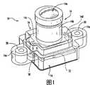
图1是根据本发明成像装置的透视图;1 is a perspective view of an imaging device according to the present invention;
图2是图1的成像装置的另一个透视图;Figure 2 is another perspective view of the imaging device of Figure 1;
图3是图1的成像装置的部分剖视和透视图;3 is a partial cutaway and perspective view of the imaging device of FIG. 1;
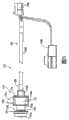
图4是根据本发明的另一个成像装置的透视图;4 is a perspective view of another imaging device according to the present invention;
图5是图4的成像装置的侧视图;5 is a side view of the imaging device of FIG. 4;
图6是图4和图5的成像装置的分解透视图;6 is an exploded perspective view of the imaging device of FIGS. 4 and 5;
图7是沿着电缆的一部分观察的图4-6的成像装置的端部视图;Figure 7 is an end view of the imaging device of Figures 4-6 looking along a portion of the cable;
图8是沿着图7的线VIII-VIII截取的成像装置的剖视图;8 is a cross-sectional view of the imaging device taken along line VIII-VIII of FIG. 7;
图9是图4-8的成像装置的透视图;Figure 9 is a perspective view of the imaging device of Figures 4-8;
图10是沿着成像装置的透镜观察的成像装置的端部视图;Figure 10 is an end view of the imaging device viewed along the lens of the imaging device;
图11是在成像装置的电缆连接端处观察的成像装置的端部视图,其中电缆被移除;Figure 11 is an end view of the imaging device as viewed at the cable connection end of the imaging device with the cable removed;
图12-15是根据本发明另一个成像装置的透视图;12-15 are perspective views of another imaging device according to the present invention;
图16是沿着图15中的线XVI-XVI截取的成像装置的剖视图;16 is a cross-sectional view of the imaging device taken along line XVI-XVI in FIG. 15;
图17是沿着图15中的线XVII-XVII截取的成像装置的剖视图;17 is a cross-sectional view of the imaging device taken along line XVII-XVII in FIG. 15;
图18是图12-15的成像装置的外壳部分的透视图;Figure 18 is a perspective view of a housing portion of the imaging device of Figures 12-15;
图19是图18的外壳部分的另一个透视图;Figure 19 is another perspective view of the housing portion of Figure 18;
图20是图12-15的成像装置的外壳部分或者盖子的透视图;和Figure 20 is a perspective view of a housing portion or cover of the imaging device of Figures 12-15; and
图21是图20的外壳部分的相对的透视图。FIG. 21 is an opposing perspective view of the housing portion of FIG. 20 .
具体实施方式Detailed ways
下面参考附图和其中所示的说明性实施例,摄像机或者成像装置或模块10适用于用在车辆上或车辆中或者车辆,并且与车辆的至少一个视觉系统相连。摄像机模块10包括电路板或芯片或元件12(成像传感器和相关的电路建立在其上)、透镜组件14和模制的密封装置或者包覆成型件或者外壳16。透镜组件14固定或者连接到电路板12,从而,透镜镜片或者镜片14a用于将透镜镜片的视场处的场景的图像聚焦和引导和折射到成像传感器上。外壳16模制在电路板12上方和周围,并且模制到透镜组件14的一部分上方,从而基本或者完全地将电路板12和电路包围或者封装在模制的外壳16内,如下面所述。Referring now to the drawings and the illustrative embodiments shown therein, a camera or imaging device or
摄像机或者成像装置模块10的电路板或者元件12包括摄像机或者图像捕获装置或传感器,用于捕获车辆外部或者内部发生的场景的图像。摄像机模块10可以使用下列美国专利申请中描述的摄像机的各个方面,由Bingle等于2005年5月11日提交的No.10/534,632,名为IMAGING SYSTEM FOR VEHICLE(Attorney Docket DON01 P-1118);和/或No.11/201,661,2005年8月11日提交,并且在2006年2月23日公开为美国公开No.US-2006-0038668A1(Attorney DocketDON01 P-1233),所述专利在此整体引为参考。可选的,由成像传感器捕获的图像可以被发送到显示器或者显示系统,所述显示器或者显示系统可操作以向车辆的驾驶员显示所述图像。可与本发明一起使用的摄像机或者成像传感器可包括成像阵列传感器,例如CMOS传感器或者CCD传感器等,例如在通常受让的美国专利No.5,550,677、5,670,935、5,796,094和6,097,023中公开的,以及在美国专利申请No.09/441,341中公开,1999年11月16日由Schofield等提交,名为VEHICLEHEADLIGHT CONTROL USING IMAGING SENSOR(Attorney Docket DON01P-770),在此整体引为参考。The circuit board or
如图1-3所示,外壳16模制在电路板12上方和周围,从而基本封闭和封装电路板12和位于其上的相关电路12a。在将外壳16模制在电路板12和电路12a上方和周围之前,透镜组件14连接到电路板12,从而形成透镜和电路板子组件。如图3所示,透镜组件14包括透镜保持器或大致圆柱形的壳体14b,所述壳体14b可在其中容纳透镜镜片14a,以提供外部透镜或镜片14a和透镜的焦点或者聚焦位置(当透镜组件连接到电路板12时,其在成像传感器处)之间的光学路径。透镜组件14的透镜保持器还包括位于大致圆柱形壳体14b的基部处的安装基座或者部分14c。如图3所示,安装基座14c可包括翼片14d,用于接纳固定件18,固定件18用于将透镜组件14连接到电路板12,如下面所述。透镜镜片或者镜片14a可调节地被定位在壳体14b处,例如通过螺纹连接等,从而有助于根据透镜组件的特定应用来调节透镜的焦点。As shown in FIGS. 1-3,
安装基座14c可以通过一对固定件18连接到电路板12,固定件18延伸穿过翼片14d和电路板12中的开口(所述开口可以是螺纹孔),从而将透镜组件14固定到电路板12,并且形成电路板和透镜子组件。如图2所示,电路板12接纳和连接到透镜组件14,从而透镜组件从电路板的表面(成像传感器位于其处的表面)向外突出。电路板12还包括电路12a,例如与成像传感器相连的电路,其中一些电路位于电路板12的相反侧或者表面处,并且因此没有被透镜组件包围或者覆盖。Mounting
外壳16模制在电路板12和透镜保持器上方和周围,包括透镜组件14的安装基座14c和/或圆柱形壳体14b,从而基本或者完全将电路板和电路包围/封装在壳体或者外壳内。外壳16还可以模制成具有从其处延伸的安装翼片或者部分16a,用于将摄像机模块10连接或者安装到车辆。可选的,安装翼片16a可具有嵌入成型在其中的加强元件或者柱或凸起(boss)20等,从而为安装翼片16a提供结构强度和刚度。外壳可以模制成容纳电路板12上的电路,并且外壳的形状可以根据电路板上不同电路部件的尺寸和设置来选择。例如如图3所示,外壳16可包括突起部分16b,该部分向外突出,从而在电路板12处的一个或者多个较大电路部件(例如图2中的电容器12b)上方和周围提供充分的壳体材料或者壁厚。
虽然图1-3未示出,但是摄像机模块10可以在它的外表面处包括连接器,例如插头或者插口类型的连接器等,用于连接到车辆的电连接器,从而为摄像机模块提供能量和控制和信号通讯。例如,电路板可包括从其处向外延伸的终端,例如多个针等,并且外壳可模制在终端周围,从而终端可以从外壳的外表面接近,从而,终端可以方便地连接到车辆连接器或者线路等。外壳因此形成为保持终端的至少一部分被暴露,例如在外壳的表面中的凹陷处,或者终端可以从外壳的表面向外突出,用于电连接到车辆线路和连接器。Although not shown in FIGS. 1-3, the
外壳16可包括任何适合的材料,例如塑料或者聚合材料,所述材料可以包覆成型(overmold)在透镜和电路板子组件周围。优选的,外壳材料包括柔软的塑料材料,所述材料可以在低压模制,以限制或者基本防止在模制过程中对于电路板处的电路的破坏。例如,外壳材料可包括低压成形的热熔树脂,例如可以从Bostik,Inc.of Middleton,MA等购买的树脂。这种树脂包括BOSTIK


可选的,外壳可在塑料材料内包括含铁的材料或者成分(优选是不传导的含铁成分),从而,包覆成型的外壳可以为EMC提供屏蔽特性,并且因此增强摄像机模块的性能。可选的,薄的低压保护性壳体可以模制在电路板和电路以及透镜组件的一部分上方,并且外壳可以是包覆成型的薄的保护性壳体,从而提供外壳的适合的厚度和外部强度以及电路板和电路的适合的保护。例如,这种内壳和外壳可以利用美国专利申请No.10/256,707中描述的各个方面来模制,该申请2002年9月27日由March等人提出,名为VEHICLE HANDLE ASSEMBLY WITH ANTENNA,现在是美国专利No.6,977,619(Attorney Docket DON01 P-1005),该专利在此整体引为参考。Optionally, the housing may include a ferrous material or composition (preferably a non-conductive ferrous composition) within the plastic material, whereby the overmolded housing may provide shielding properties for EMC and thus enhance the performance of the camera module. Optionally, a thin low voltage protective housing can be molded over the circuit board and circuitry and a portion of the lens assembly, and the housing can be an overmolded thin protective housing, providing a suitable thickness and exterior of the housing. Strength and suitable protection of boards and circuits. For example, such inner and outer shells can be molded using aspects described in U.S. Patent Application No. 10/256,707, filed September 27, 2002 by March et al., entitled VEHICLE HANDLE ASSEMBLY WITH ANTENNA, now is U.S. Patent No. 6,977,619 (Attorney Docket DON01 P-1005), which is hereby incorporated by reference in its entirety.
可选的,参考图4-11,摄像机或者成像装置或模块110适用于用在车辆上或车辆中或车辆,并且与车辆的至少一个视觉系统相连。摄像机模块110包括电路板或芯片或元件112(成像传感器112b和相关的电路112a位于其上)、透镜组件114和壳体或者机壳115,其包括模制的密封装置或者包覆成型或者外壳或者部分116和透镜保持器或者透镜安装机壳或壳体或部分117。如图6所示,电路板112可安装或者连接到透镜安装部分117,并且包覆成型部分116模制到电路板112上方和周围,并且模制到透镜安装部分117的腔中,从而基本或者完全地将电路板112和电路112a封闭或封装在壳体115的包覆成型部分116和透镜安装部分117内,如下面所述。摄像机模块110还包括电缆或者束线122,其电连接到电路板112的电路,并且包括电连接器或者连接器124a、124b,所述连接器可电连接到车辆的电路或者束线等,从而在车辆和摄像机模块之间提供电能和通讯和控制。Optionally, referring to FIGS. 4-11 , the camera or imaging device or
透镜安装部分117可包括模制塑料壳体,该壳体具有一个或多个安装元件或结构或翼片117a,用于将摄像机模块110安装或连接到车辆,例如车辆的外部,例如车辆的后方外部,用于捕获车辆后部区域的图像,例如用于倒车辅助系统或者后视系统等。透镜安装部分117可包括任何适合的塑料或者聚合材料,例如耐用的工程塑料或者其它适合的塑料材料,同时不影响本发明的范围。The
透镜安装部分117包括透镜接纳或者安装结构117b,所述结构117b从透镜安装部分117的表面突出,并且限定了通道117c,用于至少部分地接纳透镜组件,并且用于提供穿过透镜组件114并到达电路板112处的成像传感器的光学路径。透镜安装部分117包括外侧壁,该外侧壁配合以限定一腔或者凹口,用于在其中接纳电路板112,并且可包括成像传感器接纳通道117d(图8),用于当电路板安装到透镜安装部分117时接纳和/或对准电路板112的成像传感器112b,如下面所述。透镜安装部分117的外侧壁可具有形成穿过其中的孔口117e(图6),用于当壳体模制到透镜安装部分117和模制到部分117中时在其中接纳模制壳体116的模制翼片116a,如下面所述。The
透镜组件114连接到透镜安装部分117的透镜接纳结构117b,从而与设置在电路板112处的成像传感器基本对准,从而,透镜镜片或者镜片114a用于将透镜镜片的视场处的场景的图像聚焦、引导和折射到成像传感器112b上。优选的,透镜组件114被旋入圆柱形透镜接纳结构117b中,以将透镜固定到透镜安装部分117,并且基本将透镜组件相对于透镜安装部分密封。在所示实施例中,透镜组件114包括大致圆柱形的壳体114b,壳体114b可以在其中容纳透镜镜片114a,以提供外部透镜或镜片114a和透镜的焦点或聚焦位置(当透镜组件连接到透镜接纳结构117b、并且电路板112连接到透镜安装部分117时,其在成像传感器处)之间的光学路径。透镜镜片或者镜片114a被可调节地定位在透镜接纳结构117b处,例如通过螺纹连接等,从而有助于根据透镜组件的特定应用来调节透镜的焦点。如图6所示,透镜组件114包括安装部分114c,用于旋入透镜接纳结构117b中,并且包括外部垫圈或者密封装置114d,用于当安装到其处时将透镜密封或者基本密封在车辆上。The
可选的,并且适合的,粘结剂或者密封剂或者结合剂可以应用到螺纹接头,以基本将透镜组件密封在透镜安装元件处。粘结剂或密封剂或结合剂可以包括任何适合的材料,例如,厌氧材料(例如用于下面的应用,其中,安装部分114c和透镜接纳结构117b都包括金属材料),例如,LOCTITE

在所示实施例中,并且参考图6和图8,电路板112通过一对固定件118固定或者连接或者安装到透镜安装部分117,所述固定件118延伸穿过电路板112中、或穿过电路板112的开口,并且延伸到透镜安装部分117c处或者其中的开口(例如螺纹开口),从而形成电路板子组件。电路板112包括电路112a,例如与成像传感器112b相连的电路。当安装到透镜安装部分117时,电路板112接纳在腔或者凹口内,所述腔或者凹口由透镜安装部分117的外壁限定,其中一些电路位于与透镜安装部分117的透镜接纳结构117b相反的电路板112的侧或者表面。透镜安装部分117的通道117d有助于对准或者设置所述成像传感器112b,从而与接纳在透镜接纳结构117b中的透镜114的透镜镜片对准,从而,由透镜114聚焦的图像被聚焦在成像传感器112b的成像平面上。当安装在透镜安装部分117处时,电路板可以紧靠透镜安装部分的内表面被挤压或者密封,从而,成像传感器112b基本密封在通道117d内,从而,在下面描述的包覆成型过程中,包覆成型部分116的包覆成型材料没有侵入到通道117d中。In the embodiment shown, and with reference to FIGS. through the opening of the
包覆成型部分116模制到电路板子组件(包括透镜安装部分117和电路板112),从而将电路板和相连的电路基本封闭和封装和密封在壳体或者机壳115内。如图6和图8所示,包覆成型部分116模制在电路板112上方和周围,并且在透镜安装部分117的腔或者凹口内。包覆成型部分116因此填充或者基本填充透镜安装部分117的凹口,以将包覆成型部分连接到透镜安装部分,并且从而将电路板和电路密封或基本密封在其中。可选的,包覆成型部分可以形成为具有一个或者多个安装翼片(例如与透镜接纳部分117的安装翼片117a类似的安装翼片),用于安装用于车辆的摄像机模块,同时落在本发明的精神和范围内。The
包覆成型部分可以模制和形成或者成形为接纳电路板112上的电路,并且包覆成型部分的形状可以根据电路板处的不同电路部件的尺寸和设置来选择。例如,包覆成型部分116可以包括突出部分116b,该部分向外突出,从而提供一个或多个较大电路部件上方和周围的足够的壳体材料或者壁厚,所述电路部件例如电连接器112c,位于电路板112处并且从其处延伸。包覆成型部分可以模制在电连接器112c上方,其中连接器的终端被暴露在包覆成型部分的外端部处的孔口或者开口处,或者在包覆成型所述外壳或者包覆成型部分之前,摄像机模块束线122可以电连接到所述电连接器112c,从而,束线连接基本被密封和封装在包覆成型部分内,如下面所述。The overmold portion may be molded and formed or shaped to receive circuitry on the
包覆成型部分116可包括任何适合的材料,例如塑料或者聚合材料,其可以包覆成型在透镜和电路板子组件周围。优选的,并且与上述的外壳16类似,包覆成型部分材料包括柔软的塑料材料,该材料可以在低压模制,从而限制或者基本防止在模制过程中对电路板处的电路的破坏。例如,包覆成型部分材料可包括低压模制热熔树脂,例如可以从Bostik Inc.of Middleton,MA等购买的树脂。这种树脂包括BOSTIK


优选的,包覆成型部分以下面所述的方式模制到透镜安装部分,或者模制到其处或者其中,该方式也就是将包覆成型部分机械地固定到透镜安装部分或者机壳。例如,并且如图4-6和图9所示,包覆成型部分116模制成使得,包覆成型部分116的翼片或者突起116a模制到透镜安装部分117的开口或者孔口117e中,并且至少部分穿过其中,从而,在包覆成型部分被模制到其处之后,翼片116a机械地将包覆成型部分116固定到透镜安装部分117。例如,电路板子组件可以放置在模具中,其中模腔在其中接纳所述透镜安装部分117,并且在透镜安装部分的外表面处并且沿着外表面提供模腔壁,甚至在下面的区域处也一样,即开口或者孔口形成穿过所述透镜安装部分的壁的区域处。因此,当包覆成型部分被模制在透镜安装部分中时,模制材料流动穿过透镜安装部分中的孔口,并且包覆成型部分形成有翼片,所述翼片延伸穿过孔口,并且通常与透镜安装部分的外表面齐平。其它用于将包覆成型部分与透镜安装部分固定或者机械固定的装置也可以使用,同时落在本发明的精神和范围内。Preferably, the overmolded part is molded to, at or into the lens mounting part in the manner described below, ie mechanically securing the overmolded part to the lens mounting part or the housing. For example, and as shown in FIGS. 4-6 and 9, the
优选的,用于透镜安装部分117和包覆成型部分116的材料被选择使得:当包覆成型部分在透镜安装部分处并且部分在透镜安装部分内被模制和凝固时,材料可以结合或者粘着到一起。例如,包覆成型部分的较柔软的材料可以结合到透镜安装部分的较硬的材料,从而进一步将包覆成型部分固定到透镜安装部分,并且因此基本将电路板密封和封装在壳体114内。Preferably, the materials for the
在所示的实施例中,摄像机模块110包括束线122,所述束线包括位于引线或者电缆122b的端部处的电连接器122a(图6),例如插头或者插座类型的连接器等,用于将束线电连接到电路板112的连接器112c。连接器122a可以连接到连接器112c(例如通过插入其中),从而将束线电连接到摄像机模块110的电路,从而,束线122的相反端部处的连接器或者多个连接器124a、124b可以电连接到车辆的电连接器,从而向摄像机模块提供能量、控制和信号通讯。可选的,在包覆成型部分116的包覆成型之前,束线122的连接器122a可以连接到电路板112的连接器112c,从而,包覆成型部分116可以包覆成型在连接器112c上方,并且至少部分在连接器122a和/或引线122b上方,从而基本密封所述束线和模块的连接。这种密封的或者包覆成型的连接可以提供保持连接、同时不需要连接器处锁定特征的方式,并且可以降低应力,或者在到摄像机模块的连接部位处为束线提供应力释放。可选的,摄像机模块110可以包括引线套(wire sleeve)126,该引线套可以定位在束线的连接器端部处,从而封装或者封闭所述束线,从而,包覆成型部分在束线的连接器端部处封装所述引线套。包覆成型部分因此基本封闭或者封装束线和电路板之间的电连接部分,并且可以保持该连接,并且可以降低束线到摄像机模块电路板的连接部分处的应力。In the illustrated embodiment, the
因此,可以提供透镜安装部分,并且电路板或者电路元件可以连接到其处并且部分位于其中,其中成像传感器或者摄像机接纳在其内,并且位于透镜安装部分的对齐/设置部分或者通道处。束线122的连接器122a可以连接到电路板112的连接器112c,从而电路板、束线和透镜安装部分子组件可以放置在模腔中或者模腔处,用于在电路板处和周围包覆成型所述包覆成型部分。包覆成型材料可以被模制(例如通过注射成形)在电路板和电路周围,并且在透镜安装部分的腔内,并且在连接器122a、112c周围,从而将电路板和连接器基本密封和封装在包覆成型部分内。因此,并且如包括单独的元件或部件的图6所示,直到在电路板连接到透镜安装部分之后,并且在束线连接到电路板之后,包覆成型部分116才形成,从而,包覆成型部分模制在电路板和连接器上方,从而基本将电路和电连接器固定、密封和封装在摄像机模块内。Thus, a lens mounting portion may be provided and a circuit board or circuit element may be attached to and partly located therein with the imaging sensor or camera received therein and at an alignment/setting portion or channel of the lens mounting portion. The
可选的,并且参考图12-21,摄像机或者成像装置或者模块210适用于用在车辆上、车辆中或者车辆,并且与车辆的至少一个视觉系统相连。摄像机模块210包括电路板或者芯片或者元件212(成像传感器和相连的电路位于其上)、透镜组件214和壳体或者机壳215,其包括背盖部分216、和透镜保持器或者透镜安装机壳或壳体或部分217。参考图16、17所示,电路板212可安装或者连接到透镜安装部分217(例如通过螺纹紧固件等),并且盖部216固定到透镜安装部分217,并且与透镜安装部分217密封或者基本密封,从而基本或者完全地将电路板212和电路封闭或封装在壳体或者机壳215内,如下面所述。摄像机模块210还包括电缆或者束线222,其电连接到电路板212的电路,并且包括电连接器224,其可以电连接到车辆等的电路或者束线,从而在车辆和摄像机模块之间提供能量和通讯和控制。Optionally, and with reference to FIGS. 12-21 , a camera or imaging device or
透镜安装部分217可包括一个或多个安装元件或结构或翼片217a,用于将摄像机模块210安装或者连接到车辆,例如在车辆的外部,例如在车辆的后方外部,用于捕获车辆后方区域的图像,例如用于倒车辅助系统,或者后视系统等。透镜安装部分217可包括任何适合的材料,例如任何适合的金属材料,例如金属材料等,例如锌合金材料等,例如,模铸的ZAMAK

透镜安装部分217包括透镜接纳或安装结构217b,该结构从透镜安装部分217的表面突出,并且限定了通道217c(图16),用于至少部分接纳透镜组件214,并且用于提供光学路径,该光学路径穿过透镜组件214,并且通向电路板212处的成像传感器。透镜安装部分217包括外侧壁,该外侧壁配合以限定腔或者凹口,用于在其中接纳电路板212,并且可包括成像传感器接纳通道,用于接纳和/或对准电路板的成像传感器,例如以与上述类似的方式。透镜安装部分可包括螺纹孔或者凸起217d,用于将电路板连接到透镜安装部分的内部,例如通过螺纹固定件等。The
透镜组件214连接到透镜安装部分217的透镜接纳结构217b,从而与设置在电路板212处的成像传感器基本对准,从而,透镜镜片或者镜片214a用于将透镜镜片的视场处的场景的图像聚焦、引导和折射到成像传感器上。优选的,透镜组件214被旋入圆柱形透镜接纳结构217b中,从而将透镜固定到透镜安装部分217,并且将透镜组件相对于透镜安装部分基本密封。在所示的实施例中,透镜组件214包括大致圆柱形的壳体,该壳体可在其中容纳透镜镜片214a,以提供外部透镜或镜片214a和透镜的焦点或聚焦位置(当透镜组件连接到透镜接纳结构217b、并且电路板212连接到透镜安装部分217时,所述位置在成像传感器处)之间的光学路径。透镜镜片或镜片214a可调节地被定位在透镜接纳结构217b处,例如通过螺纹连接装置等,以有助于根据透镜组件的特定应用来调节透镜的焦点。
可选的并且适合的,粘结剂或密封剂或结合剂可应用到螺纹接头,以将透镜组件基本密封在透镜安装元件处。粘结剂或密封剂或结合剂可包括任何适合的材料,例如厌氧材料(例如用在下面的应用,其中,透镜组件的安装部分和透镜接纳结构217b都包括金属材料),例如,LOCTITE

盖部216构造成具有接合唇部或边缘216b,该边缘216b接合透镜安装部分217的相对应的接合唇部或边缘217e,例如参见图16和17。粘结剂或密封剂的小珠(bead)可以施加在边缘周围,从而,当盖部被压靠在透镜安装部分上时,壳体或机壳围绕它的相邻部分基本被密封,从而限制或者基本防止水侵入该壳体中。所选择的粘结剂或密封剂可包括任何适合的粘结剂或结合剂,例如厌氧粘结剂(例如如果盖部和透镜安装部分是金属部件),例如,LOCTITE
因此,壳体可提供各部分之间的适合或合适的间距或间隙,用于当盖部连接到透镜安装部分时增强结合,该结合通过沿着边缘或唇部、并且因此在边缘或唇部之间的间隙内设置的粘结剂或密封剂或结合剂建立。在所示的实施例中,盖部216的边缘或唇部216b接纳在透镜安装部分217的边缘或唇部217e内,并且盖部216包括止挡唇部或凸缘216d,其限制将边缘216b插入透镜安装部分217中,从而,盖部和透镜安装部分被正确地连接和结合在一起。可选的,密封壳体215可在其中包括干燥剂材料或成分,以干燥壳体的内腔和/或吸收可能进入壳体中的任何水分,例如在将盖部连接到透镜安装部分的过程中。Thus, the housing may provide suitable or appropriate spacing or clearance between the parts for enhancing the bond when the cover is connected to the lens mounting part by Adhesive or sealant or bonding agent is provided in the gap between the establishments. In the illustrated embodiment, an edge or
在所示的实施例中,摄像机模块210包括束线222,该束线222包括电连接器224,例如插头或插座类型的连接器等,位于引线或者电缆222a的端部处,用于将束线电连接到车辆连接器或车辆束线等。束线222的摄像机模块端部可连接到(例如通过插入到其中或者焊接到其处)电路板212处的电路,从而将束线电连接到摄像机模块210的电路,从而,连接器224可以电连接到车辆的电连接器,从而向摄像机模块提供能量和控制,并且向摄像机模块和从摄像机模块提供信号通讯。In the illustrated embodiment, the
可选的,束线222可包括护套(grommet)226,该护套可连接并且可密封到摄像机模块210的壳体215的盖部216处。例如,如图17所示,护套226可以插入穿过盖部216的后壁处的开口或孔口216e,并且可包括柔性或者顺应性的材料,从而基本紧靠盖部密封,从而限制或者基本防止水通过开口或孔口216e侵入壳体215中。可选的,护套226可以通过孔口216e不可旋转地被接纳,并且可以通过翼片以适合的或者合适的或选择的定向被保持在护套226的内端部处(当护套通过盖部中的孔口被接纳时,该端部在壳体内),接合所述盖部216的内壁或表面处的一个或多个突起216f(图16和图19)。Optionally, the
因此,可以提供透镜安装部分,并且电路板或电路元件可以连接到其处,并且部分位于其中,其中成像传感器或摄像机被接纳在其内,并且位于透镜安装部分的对齐/设置部分或通道处。盖部(束线和护套连接到其处)可以设置在透镜安装部分处,并且束线可以连接到电路板(例如通过插头和插座连接或者通过焊接或者其它方式将束线的终端连接到电路板)。盖部然后被压靠在透镜安装部分上,从而将壳体固定在一起。优选的,粘结剂或其它适合的密封剂或结合材料的小珠可以被应用到透镜安装部分和/或盖部的唇部或者边缘,从而当壳体被装配时将各部分密封和结合在一起。Thus, a lens mounting portion may be provided and a circuit board or circuit element may be connected thereto and partially located therein, with an imaging sensor or camera received therein and at an alignment/setting portion or channel of the lens mounting portion. A cover (to which the harness and sheath are attached) may be provided at the lens mounting portion, and the harness may be connected to the circuit board (e.g. by plug and socket connection or by soldering or otherwise connecting the ends of the harness to the circuit plate). The cover portion is then pressed against the lens mounting portion, thereby securing the housing together. Preferably, a bead of adhesive or other suitable sealant or bonding material can be applied to the lip or edge of the lens mounting portion and/or cover to seal and bond the parts together when the housing is assembled. Together.
因此,本发明的摄像机模块提供了位于电路板或者芯片上的成像传感器和相关的电路,其被装配到透镜组件,并且基本封闭和密封在模制的外壳内。通过将外壳模制在电路板和电路周围和上方,基本保护和密封电路防止例如水或者蒸气等侵入,并且因此提供基本不透水的、坚固的摄像机模块,其非常适用于外部车辆应用。本发明的摄像机模块因此提供增强的保护,防止环境的影响,例如雨、雪、公路飞溅等,并且由于外壳材料的强度,提供物理保护,例如防止公路碎片、灰尘、尘土等。同样,通过将外壳模制在电路板上方,外壳(和整个摄像机模块)可以基本小于已知的摄像机,已知的摄像机具有位于中空壳体或机壳内的电路和传感器。在所示的实施例中,外壳可以仅比容纳在其中的电路板大或者宽大约2毫米,因此相比已知的摄像机提供了显著的尺寸减小。同样,通过将壳体模制在电路板处、周围和上方,本发明可以保持印刷电路板(PCB)连接器,同时不需要锁定特征,因为包覆成型材料可以提供这个特征,同时还为束线提供应力释放。可选的,通过将盖部密封和粘附到壳体的透镜安装部分,当装配时,壳体可以基本被密封在一起,从而限制或者基本防止水(或其它污染物)侵入到壳体中。Accordingly, the camera module of the present invention provides an imaging sensor and associated circuitry on a circuit board or chip, assembled to a lens assembly, and substantially enclosed and sealed within a molded housing. By molding the housing around and over the circuit board and circuitry, the circuitry is substantially protected and sealed from ingress such as water or vapor, and thus provides a substantially watertight, rugged camera module that is well suited for exterior vehicle applications. The camera module of the present invention thus provides enhanced protection against environmental influences, such as rain, snow, road splashes, etc., and due to the strength of the housing material, physical protection, such as against road debris, dust, dust, etc. Also, by molding the housing over the circuit board, the housing (and the entire camera module) can be substantially smaller than known cameras that have circuitry and sensors located within a hollow housing or housing. In the illustrated embodiment, the housing may be only about 2 millimeters larger or wider than the circuit board housed therein, thus providing a significant size reduction compared to known cameras. Also, by molding the housing at, around, and over the circuit board, the present invention can maintain a printed circuit board (PCB) connector without the need for a locking feature, as the overmolding material can provide this feature, while still providing protection for the bundle. Wire provides strain relief. Optionally, by sealing and adhering the cover to the lens mounting portion of the housing, the housings can be substantially sealed together when assembled, thereby limiting or substantially preventing ingress of water (or other contaminants) into the housing .
可选的是,可以想象,在本发明的包覆成型过程中,其它结构或元件可以整体模制在外壳或者盖部处。例如,摄像机组件或模块的其它部件,例如小的凸缘或支架(例如用于将摄像机模块安装在车辆上,或者用于将其它元件例如束线等连接在摄像机模块上)等,可以模制或整体形成或连接到摄像机模块的包覆成型部分。可选的,导体或者母线或电气终端或导体可以设置在包覆成型部分处,并且可以在包覆成型过程中嵌入成形在其中(例如用于在摄像机模块的包覆成型部分处或者其中提供一个或者多个电接触件)。因此,在形成外壳或者盖部的相同的模制过程中,本发明的包覆成型过程可以提供摄像机模块的其它整体部件或者元件,并且所述模制过程将电路元件或电路板和/或电路封装和/或密封在摄像机模块内。Alternatively, it is conceivable that other structures or elements may be integrally molded at the housing or cover during the overmolding process of the present invention. For example, other parts of the camera assembly or module, such as small flanges or brackets (such as for mounting the camera module on a vehicle, or for attaching other elements such as harnesses, etc. to the camera module), etc., can be molded Either integrally formed or attached to the overmolded portion of the camera module. Optionally, conductors or busbars or electrical terminals or conductors may be provided at the overmolded part and may be insert-molded therein during the overmolding process (e.g. for providing a or multiple electrical contacts). Thus, the overmolding process of the present invention can provide other integral components or elements of the camera module in the same molding process that forms the housing or cover, and the molding process incorporates circuit elements or circuit boards and/or circuitry Encapsulated and/or sealed within the camera module.
本发明的摄像机模块和电路芯片或电路板和成像传感器可以与各种车辆视觉系统一起使用和工作,和/或可以利用其它这种车辆系统的原理来操作,例如车辆照明灯控制系统,例如在下列美国专利中公开的类型:美国专利No.5,796,094;6,097,023;6,320,176;6,559,435;和6,831,261,和美国专利申请No.09/441,341,1999年11月16日由Schofield等提交,名为VEHICLE HEADLIGHT CONTROL USING IMAGINGSENSOR(Attorney Docket DON01 P-770);No.11/105,757,2005年4月14日由Schofield等提交,名为IMAGING SYSTEM FOR VEHICLE(AttorneyDocket Don01 P-1208);和/或No.10/421,281,2003年4月23日由Schofield提交,名为AUTOMATIC HEADLAMP CONTROL,现在是美国专利No.7,004,606(Attorney Docket DON01 P-1073),上述专利在此整体引为参考;雨传感器,例如在通常受让的下列美国专利中公开的类型,Nos.6,353,392,Nos.6,313,454;和/或6,320,176和/或美国专利申请No.11/201,661,2005年8月11日提交,并且在2006年2月23日公开为No.US-2006-0038668-A1(Attorney Docket DON01 P-1233),其在此整体引为参考;车辆视觉系统,例如前向、侧向、后向车辆视觉系统,利用下列美国专利中公开的原理:No.5,550,677;5,670,935;5,760,962;5,877,897;5,949,331;6,222,447;6,302,545;6,396,397;6,498,620;6,523,964;6,611,202;6,201,642;6,690,268;6,717,610;6,757,109;6,802,617;6,806,452;6,822,563;和6,891,563,和/或美国专利申请No.10/643,602,2003年8月19日由Schofield等提交,名为VISION SYSTEM FOR A VEHICLE INCLUDING IMAGING PROCESSOR(Attorney Docket DON01 P-1087);和/或No.10/422,378,2003年4月24日由Schofield等提交,名为IMAGING SYSTEM FOR VEHICLE,现在是美国专利No.6,946,978(Attorney Docket DON01 P-1074),它们在此整体引为参考,挂车连接辅助装置或者拖曳检查系统,例如下列美国专利申请中公开的类型,No.10/418,486,2003年4月18日由McMahon等提交,名为VEHICLE IMAGING SYSTEM,现在是美国专利No.7,005,974(Attorney Docket DON01 P-1070),该专利在此整体引为参考,后部或者侧向成像系统,例如用于车道变换辅助系统,或者车道偏离警告系统,或者用于盲区或者目标检测系统,例如下列文献中公开的成像或检测系统,美国专利No.5,929,786和/或5,786,772,和/或美国专利申请No.10/427,051,2003年4月30日由Pawlicki等提交,名为OBJECTDETECTION SYSTEM FOR VEHICLE,现在是美国专利No.7,038,577(Attorney Docket DON01 P-1075)No.11/239,980,2005年9月30日提交(Attorney Docket DON01 P-1238);和/或No.11/315,675,2005年12月22日提交(Attorney Docket DON01 P-1253),和/或美国临时申请No.60/628,709,2004年11月17日由Camilleri等提交,名为IMAGING AND DISPLAY SYSTEM FOR VEHICLE(Attorney Docket DON01P-1188);No.60/614,644,2004年9月30日提交(Attorney Docket DON01P-1177)No.60/618,686,2004年10月14日由Laubinger提交,名为VEHICLE IMAGING SYSTEM(Attorney Docket DON01 P-1183);No.60,638,687,2004年12月23日由Hinggins-Luthman提交,名为OBJECT DETECTION SYSTEM FOR VEHICLE(Attorney Docket DON01P-1195),这些文献在此整体引为参考,视频装置,用于内部车厢检视和/或视频电话功能,例如下列文献中公开的,美国专利No.5,760,962;5,877,897;和/或6,690,268;和/或PCT申请No.PCT/US03/40611,2003年12月19日由Donnelly Corp等提交,名为ACCESSORY SYSTEM FORVEHICLE(Attorney Docket DON01 FP-1123(PCT)),和/或美国专利申请No.11/284,543,2005年11月22日提交,并且在2006年7月27日公开为美国公开No.US2006-164230-A1(Attorney Docket DON01P-1245);和/或No.10/538,724,2005年6月13日提交,并且在2006年3月9日公开为美国公开No.US-2006-0050018-A1(Attorney DocketDON01 P-1123),和/或美国临时申请No.60/630,061,2004年11月22日由Lynam等提交,名为MIRROR ASSEMBLY WITH VIDEO DISPLAY(Attorney Docket DON01 P-1199);和No.60/667,048,2005年3月31日由Lynam等提交,名为MIRRO ASSEMBLY WITH VIDEO DISPLAY(Attorney Docket DON01 P-1212),在此整体引为参考,交通信号识别系统,用于确定到前车或者后车或者目标的距离的系统,例如利用下列文献中公开的原理的系统:美国专利No.6,396,397和/或美国专利申请No.10/422,512,2003年4月24日由Schofield提交,名为DRIVINGSEPARATION DISTANCE INDICATOR(Attorney Docket DON01 P-1072),它们在此整体引为参考。The camera module and circuit chip or circuit board and imaging sensor of the present invention can be used and operated with various vehicle vision systems, and/or can utilize the principles of other such vehicle systems to operate, such as vehicle lighting control systems, such as in 6,097,023; 6,320,176; 6,559,435; and 6,831,261, and U.S. Patent Application No. 09/441,341, filed November 16, 1999 by Schofield et al., entitled VEHICLE HEADLIGHT CONTROL USING IMAGINGSENSOR (Attorney Docket DON01 P-770); No. 11/105,757, filed April 14, 2005 by Schofield et al., entitled IMAGING SYSTEM FOR VEHICLE (Attorney Docket Don01 P-1208); and/or No. 10/421,281, AUTOMATIC HEADLAMP CONTROL, now U.S. Patent No. 7,004,606 (Attorney Docket DON01 P-1073), filed April 23, 2003 by Schofield, which is hereby incorporated by reference in its entirety; rain sensors, e.g., in commonly assigned of the type disclosed in the following U.S. Patent Nos. 6,353,392, Nos. 6,313,454; and/or 6,320,176 and/or U.S. Patent Application No. 11/201,661, filed August 11, 2005, and published on February 23, 2006 as No. US-2006-0038668-A1 (Attorney Docket DON01 P-1233), which is hereby incorporated by reference in its entirety; vehicle vision systems, such as forward, side, and rear vehicle vision systems, utilize the原理:No.5,550,677;5,670,935;5,760,962;5,877,897;5,949,331;6,222,447;6,302,545;6,396,397;6,498,620;6,523,964;6,611,202;6,201,642;6,690,268;6,717,610;6,757,109;6,802,617;6,806,452;6,822,563;和6,891,563,和/或美国专利申请No .10/643,602, filed Aug. 19, 2003 by Schofield et al., entitled VISION SYSTEM FOR A VEHICLE INCLUDIN G IMAGING PROCESSOR (Attorney Docket DON01 P-1087); and/or No. 10/422,378, filed April 24, 2003 by Schofield et al., entitled IMAGING SYSTEM FOR VEHICLE, now U.S. Patent No. 6,946,978 (Attorney Docket DON01 P-1074), which are hereby incorporated by reference in their entirety, a trailer hitch aid or tow inspection system, such as the type disclosed in the following U.S. Patent Application, No. 10/418,486, filed April 18, 2003 by McMahon et al., entitled FOR VEHICLE IMAGING SYSTEM, now U.S. Patent No. 7,005,974 (Attorney Docket DON01 P-1070), which is hereby incorporated by reference in its entirety, Rear or Side Imaging Systems, such as for Lane Change Assist, or Lane Departure Warning systems, or for blind spot or object detection systems, such as the imaging or detection systems disclosed in U.S. Patent Nos. 5,929,786 and/or 5,786,772, and/or U.S. Patent Application No. 10/427,051, April 30, 2003 Filed by Pawlicki et al., entitled OBJECTDETECTION SYSTEM FOR VEHICLE, now U.S. Patent No. 7,038,577 (Attorney Docket DON01 P-1075) No. 11/239,980, filed September 30, 2005 (Attorney Docket DON01 P-1238); and /or No. 11/315,675, filed December 22, 2005 (Attorney Docket DON01 P-1253), and/or U.S. Provisional Application No. 60/628,709, filed November 17, 2004 by Camilleri et al., entitled IMAGING AND DISPLAY SYSTEM FOR VEHICLE (Attorney Docket DON01P-1188); No. 60/614,644, filed September 30, 2004 (Attorney Docket DON01P-1177) No. 60/618,686, filed October 14, 2004 by Laubinger, For VEHICLE IMAGING SYSTEM (Attorney Docket DON01 P-1183); No. 60,638,687, filed December 23, 2004 by Hinggins-Luthman, entitled OB JECT DETECTION SYSTEM FOR VEHICLE (Attorney Docket DON01P-1195), which are hereby incorporated by reference in their entirety, Video Apparatus for Interior Car View and/or Video Telephony Functions, such as disclosed in U.S. Patent No. 5,760,962; 5,877,897; and/or 6,690,268; and/or PCT Application No. PCT/US03/40611, filed December 19, 2003 by Donnelly Corp et al., entitled ACCESSORY SYSTEM FORVEHICLE (Attorney Docket DON01 FP-1123(PCT)), and /or U.S. Patent Application No. 11/284,543, filed November 22, 2005, and published as U.S. Publication No. US2006-164230-A1 (Attorney Docket DON01P-1245) on July 27, 2006; and/or No. .10/538,724, filed June 13, 2005, and published March 9, 2006 as U.S. Publication No. US-2006-0050018-A1 (Attorney DocketDON01 P-1123), and/or U.S. Provisional Application No. 60/630,061, filed November 22, 2004 by Lynam et al., entitled MIRROR ASSEMBLY WITH VIDEO DISPLAY (Attorney Docket DON01 P-1199); and No. 60/667,048, filed March 31, 2005 by Lynam et al. For MIRRO ASSEMBLY WITH VIDEO DISPLAY (Attorney Docket DON01 P-1212), incorporated herein by reference in its entirety, a traffic signal recognition system, a system for determining the distance to a vehicle in front or behind or to an object, for example using the Principled system: U.S. Patent No. 6,396,397 and/or U.S. Patent Application No. 10/422,512, filed April 24, 2003 by Schofield, entitled DRIVINGSEPARATION DISTANCE INDICATOR (Attorney Docket DON01 P-1072), which are incorporated herein in their entirety for reference.
可选的,电路板或者芯片可以包括用于成像阵列传感器的电路和或其它电子附件或者特征,例如通过利用compass-on-a-chip或者ECdriver-on-a-chip技术,以及例如在下列文献中描述的各个方面:美国专利申请No.11/021,065,2004年12月23日由McCabe等提交,名为ELECTRO-OPTIC MIRROR CELL(Attorney Docket DON01 P-1193);No.11/201,661,2005年8月11日由Deward等提交,名为ACCESSORYMODULE FOR VEHICLE(Attorney Docket DON01 P-1233);和/或No.11/226,628,2005年9月14日由Karner等提交(Attorney DocketDON01 P-1236),在此整体引为参考。Optionally, the circuit board or chip may include circuitry and or other electronic accessories or features for the imaging array sensor, for example by utilizing compass-on-a-chip or ECdriver-on-a-chip technology, and for example in the following documents Aspects described in: U.S. Patent Application No. 11/021,065, filed December 23, 2004, by McCabe et al., entitled ELECTRO-OPTIC MIRROR CELL (Attorney Docket DON01 P-1193); No. 11/201,661, 2005 ACCESSORYMODULE FOR VEHICLE, filed Aug. 11 by Deward et al. (Attorney Docket DON01 P-1233); and/or No. 11/226,628, filed Sept. 14, 2005 by Karner et al. (Attorney Docket DON01 P-1236), It is hereby incorporated by reference in its entirety.
可选的,摄像机或者成像装置可以定位在车辆的内部后视镜组件处,并且可以位于镜子组件中,并且相对于车辆行进方向大致向前或者向后,用于沿着向前或者向后方向提供外部视场。可选的,摄像机或者成像装置可以朝向车厢内的一个或多个位置,从而提供内部视场,例如用于车厢监测系统等。Optionally, a camera or imaging device may be positioned at the interior rearview mirror assembly of the vehicle, and may be located in the mirror assembly, and generally forward or rearward relative to the direction of travel of the vehicle, for Provides external field of view. Optionally, the camera or the imaging device may be directed towards one or more positions in the vehicle compartment, so as to provide an internal field of view, for example, for a vehicle compartment monitoring system and the like.
详细描述的变化和变形可以在不脱离本发明原理的情况下进行,该原理仅由根据专利法原理解释的权利要求的范围限定。Changes and modifications to the detailed description may be made without departing from the principles of the invention, which are limited only by the scope of the claims construed in accordance with the principles of patent law.
Claims (18)
Applications Claiming Priority (3)
| Application Number | Priority Date | Filing Date | Title |
|---|---|---|---|
| US73118305P | 2005-10-28 | 2005-10-28 | |
| US60/731,183 | 2005-10-28 | ||
| PCT/US2006/041709WO2007053404A2 (en) | 2005-10-28 | 2006-10-27 | Camera module for vehicle vision system |
Publications (1)
| Publication Number | Publication Date |
|---|---|
| CN101816008Atrue CN101816008A (en) | 2010-08-25 |
Family
ID=38006389
Family Applications (1)
| Application Number | Title | Priority Date | Filing Date |
|---|---|---|---|
| CN200680049414APendingCN101816008A (en) | 2005-10-28 | 2006-10-27 | Camera module for vehicle vision system |
Country Status (4)
| Country | Link |
|---|---|
| US (1) | US20090244361A1 (en) |
| EP (1) | EP1946540A4 (en) |
| CN (1) | CN101816008A (en) |
| WO (1) | WO2007053404A2 (en) |
Cited By (11)
| Publication number | Priority date | Publication date | Assignee | Title |
|---|---|---|---|---|
| CN104348041A (en)* | 2013-07-29 | 2015-02-11 | 日本航空电子工业株式会社 | Electronic device module |
| CN105093469A (en)* | 2014-05-07 | 2015-11-25 | 奥托立夫开发公司 | Camera module for a motor vehicle and method of mounting a camera module |
| CN105163006A (en)* | 2014-05-07 | 2015-12-16 | 奥托立夫开发公司 | Automobile imaging system and method for installing imaging system |
| CN105383382A (en)* | 2014-08-21 | 2016-03-09 | 罗伯特·博世有限公司 | Monitoring System for a Motor Vehicle, Plug-On Module |
| CN107005631A (en)* | 2014-11-26 | 2017-08-01 | 松下知识产权经营株式会社 | Camera device |
| CN107206937A (en)* | 2014-12-31 | 2017-09-26 | 金泰克斯公司 | Backsight vehicle camera |
| CN109541582A (en)* | 2017-09-21 | 2019-03-29 | 维宁尔美国公司 | Detection system and detection system for vehicle |
| CN110154928A (en)* | 2018-02-15 | 2019-08-23 | 通用汽车环球科技运作有限责任公司 | Paperback sensor leads component |
| CN114689169A (en)* | 2018-08-03 | 2022-07-01 | 原相科技股份有限公司 | Optical sensor assembly |
| CN115066595A (en)* | 2020-02-17 | 2022-09-16 | 索尼半导体解决方案公司 | Sensor module and method for manufacturing sensor module |
| CN115103092A (en)* | 2011-11-22 | 2022-09-23 | 康耐视公司 | Vision system camera with mount for multiple lens types |
Families Citing this family (127)
| Publication number | Priority date | Publication date | Assignee | Title |
|---|---|---|---|---|
| WO2004047421A2 (en) | 2002-11-14 | 2004-06-03 | Donnelly Corporation | Imaging system for vehicle |
| US8698894B2 (en) | 2006-02-07 | 2014-04-15 | Magna Electronics Inc. | Camera mounted at rear of vehicle |
| EP2122599B1 (en) | 2007-01-25 | 2019-11-13 | Magna Electronics Inc. | Radar sensing system for vehicle |
| US8482664B2 (en)* | 2008-10-16 | 2013-07-09 | Magna Electronics Inc. | Compact camera and cable system for vehicular applications |
| JP5474077B2 (en)* | 2008-10-20 | 2014-04-16 | サバンジ・ウニヴェルシテシ | Car camera |
| DE102008057432A1 (en)* | 2008-11-07 | 2010-05-12 | Dr.Ing.H.C.F.Porsche Aktiengesellschaft | Arrangement of a headlight pot, a sensor and a protective plate for the sensor in a vehicle |
| WO2010091347A1 (en)* | 2009-02-06 | 2010-08-12 | Magna Electronics Inc. | Improvements to camera for vehicle |
| WO2010099416A1 (en) | 2009-02-27 | 2010-09-02 | Magna Electronics | Alert system for vehicle |
| ES2693455T3 (en) | 2009-03-25 | 2018-12-11 | Magna Electronics Inc. | Camera assembly and vehicular lens |
| US12328491B1 (en) | 2009-03-25 | 2025-06-10 | Magna Electronics Inc. | Vehicular camera and lens assembly |
| US8376595B2 (en) | 2009-05-15 | 2013-02-19 | Magna Electronics, Inc. | Automatic headlamp control |
| KR101207715B1 (en)* | 2010-11-03 | 2012-12-03 | 엘지이노텍 주식회사 | Camera and method for manufacturing the same |
| WO2012068331A1 (en) | 2010-11-19 | 2012-05-24 | Magna Electronics Inc. | Lane keeping system and lane centering system |
| DE102011010624B4 (en)* | 2011-02-08 | 2014-10-16 | Mekra Lang Gmbh & Co. Kg | Display device for fields of view of a commercial vehicle |
| WO2012116043A1 (en) | 2011-02-25 | 2012-08-30 | Magna Electronics Inc. | Vehicular camera with aligned housing members and electrical connection between aligned housing members |
| US9194943B2 (en) | 2011-04-12 | 2015-11-24 | Magna Electronics Inc. | Step filter for estimating distance in a time-of-flight ranging system |
| WO2012145313A2 (en) | 2011-04-18 | 2012-10-26 | Magna Electronics Inc. | Vehicular camera with variable focus capability |
| US9380219B2 (en) | 2011-04-20 | 2016-06-28 | Magna Electronics Inc. | Angular filter for vehicle mounted cameras |
| WO2012145819A1 (en) | 2011-04-25 | 2012-11-01 | Magna International Inc. | Image processing method for detecting objects using relative motion |
| CN103858425B (en) | 2011-08-02 | 2018-03-30 | 马格纳电子系统公司 | Vehicle camera system |
| US9871971B2 (en) | 2011-08-02 | 2018-01-16 | Magma Electronics Inc. | Vehicle vision system with light baffling system |
| US20140218535A1 (en) | 2011-09-21 | 2014-08-07 | Magna Electronics Inc. | Vehicle vision system using image data transmission and power supply via a coaxial cable |
| US9681062B2 (en) | 2011-09-26 | 2017-06-13 | Magna Electronics Inc. | Vehicle camera image quality improvement in poor visibility conditions by contrast amplification |
| KR20130055130A (en)* | 2011-11-18 | 2013-05-28 | 엘지이노텍 주식회사 | Camera unit for vehicle |
| US10099614B2 (en) | 2011-11-28 | 2018-10-16 | Magna Electronics Inc. | Vision system for vehicle |
| WO2013103548A1 (en) | 2012-01-05 | 2013-07-11 | Magna Electronics, Inc. | Camera module for vehicle vision system |
| US20130215271A1 (en) | 2012-02-22 | 2013-08-22 | Magna Electronics, Inc. | Indicia and camera assembly for a vehicle |
| US8694224B2 (en) | 2012-03-01 | 2014-04-08 | Magna Electronics Inc. | Vehicle yaw rate correction |
| US9565342B2 (en) | 2012-03-06 | 2017-02-07 | Magna Electronics Inc. | Vehicle camera with tolerance compensating connector |
| US10609335B2 (en) | 2012-03-23 | 2020-03-31 | Magna Electronics Inc. | Vehicle vision system with accelerated object confirmation |
| US9751465B2 (en) | 2012-04-16 | 2017-09-05 | Magna Electronics Inc. | Vehicle vision system with reduced image color data processing by use of dithering |
| US9058706B2 (en)* | 2012-04-30 | 2015-06-16 | Convoy Technologies Llc | Motor vehicle camera and monitoring system |
| US10089537B2 (en) | 2012-05-18 | 2018-10-02 | Magna Electronics Inc. | Vehicle vision system with front and rear camera integration |
| KR101416309B1 (en)* | 2012-06-01 | 2014-07-09 | (주)에이엔피 크리비즈 | manufacturing method of Integral connector camera for vehicle |
| US9340227B2 (en) | 2012-08-14 | 2016-05-17 | Magna Electronics Inc. | Vehicle lane keep assist system |
| DE102013217430A1 (en) | 2012-09-04 | 2014-03-06 | Magna Electronics, Inc. | Driver assistance system for a motor vehicle |
| US9743002B2 (en) | 2012-11-19 | 2017-08-22 | Magna Electronics Inc. | Vehicle vision system with enhanced display functions |
| US9090234B2 (en) | 2012-11-19 | 2015-07-28 | Magna Electronics Inc. | Braking control system for vehicle |
| US10025994B2 (en) | 2012-12-04 | 2018-07-17 | Magna Electronics Inc. | Vehicle vision system utilizing corner detection |
| US9481301B2 (en) | 2012-12-05 | 2016-11-01 | Magna Electronics Inc. | Vehicle vision system utilizing camera synchronization |
| US20140218529A1 (en) | 2013-02-04 | 2014-08-07 | Magna Electronics Inc. | Vehicle data recording system |
| US9092986B2 (en) | 2013-02-04 | 2015-07-28 | Magna Electronics Inc. | Vehicular vision system |
| US10027930B2 (en) | 2013-03-29 | 2018-07-17 | Magna Electronics Inc. | Spectral filtering for vehicular driver assistance systems |
| US9327693B2 (en) | 2013-04-10 | 2016-05-03 | Magna Electronics Inc. | Rear collision avoidance system for vehicle |
| US10232797B2 (en) | 2013-04-29 | 2019-03-19 | Magna Electronics Inc. | Rear vision system for vehicle with dual purpose signal lines |
| US10567705B2 (en) | 2013-06-10 | 2020-02-18 | Magna Electronics Inc. | Coaxial cable with bidirectional data transmission |
| US9260095B2 (en) | 2013-06-19 | 2016-02-16 | Magna Electronics Inc. | Vehicle vision system with collision mitigation |
| US9609757B2 (en) | 2013-06-24 | 2017-03-28 | Magna Electronics Inc. | Vehicle vision system camera assembly with coaxial connector |
| US20140375476A1 (en) | 2013-06-24 | 2014-12-25 | Magna Electronics Inc. | Vehicle alert system |
| US9619716B2 (en) | 2013-08-12 | 2017-04-11 | Magna Electronics Inc. | Vehicle vision system with image classification |
| US10326969B2 (en) | 2013-08-12 | 2019-06-18 | Magna Electronics Inc. | Vehicle vision system with reduction of temporal noise in images |
| US9451138B2 (en) | 2013-11-07 | 2016-09-20 | Magna Electronics Inc. | Camera for vehicle vision system |
| US9499139B2 (en) | 2013-12-05 | 2016-11-22 | Magna Electronics Inc. | Vehicle monitoring system |
| US9988047B2 (en) | 2013-12-12 | 2018-06-05 | Magna Electronics Inc. | Vehicle control system with traffic driving control |
| DE102013021622A1 (en) | 2013-12-18 | 2015-07-02 | Mekra Lang Gmbh & Co. Kg | Camera for vehicle, in particular commercial vehicle |
| US10298823B2 (en) | 2014-02-03 | 2019-05-21 | Magna Electronics Inc. | Vehicle camera housing with tolerance compensating connector |
| US10017114B2 (en) | 2014-02-19 | 2018-07-10 | Magna Electronics Inc. | Vehicle vision system with display |
| US9749509B2 (en) | 2014-03-13 | 2017-08-29 | Magna Electronics Inc. | Camera with lens for vehicle vision system |
| US9623878B2 (en) | 2014-04-02 | 2017-04-18 | Magna Electronics Inc. | Personalized driver assistance system for vehicle |
| US9896039B2 (en) | 2014-05-09 | 2018-02-20 | Magna Electronics Inc. | Vehicle vision system with forward viewing camera |
| US9621769B2 (en) | 2014-06-11 | 2017-04-11 | Magna Electronics Inc. | Camera module for vehicle vision system |
| US20160006908A1 (en)* | 2014-07-03 | 2016-01-07 | Delphi Technologies, Inc. | Molded camera |
| JP6638151B2 (en) | 2014-07-04 | 2020-01-29 | 日本電産コパル株式会社 | Imaging device |
| US10137844B2 (en) | 2014-08-04 | 2018-11-27 | Magna Electronics Inc. | Vehicle camera having molded interconnect device |
| US9961241B2 (en) | 2014-08-04 | 2018-05-01 | Magna Electronics Inc. | Vehicle vision system with camera having molded interconnect device |
| WO2016022373A1 (en)* | 2014-08-05 | 2016-02-11 | Seek Thermal, Inc. | Method of producing a low reflecity lems mount for infrared camera |
| US9925980B2 (en) | 2014-09-17 | 2018-03-27 | Magna Electronics Inc. | Vehicle collision avoidance system with enhanced pedestrian avoidance |
| KR102248085B1 (en) | 2014-10-17 | 2021-05-04 | 엘지이노텍 주식회사 | Camera module using for automobile |
| CN205249352U (en) | 2014-12-17 | 2016-05-18 | 日本电产科宝株式会社 | Vehicle -mounted image recognition device |
| KR102293357B1 (en)* | 2015-01-12 | 2021-08-25 | 엘지이노텍 주식회사 | Camera module |
| US9764744B2 (en) | 2015-02-25 | 2017-09-19 | Magna Electronics Inc. | Vehicle yaw rate estimation system |
| US10078207B2 (en)* | 2015-03-18 | 2018-09-18 | Endochoice, Inc. | Systems and methods for image magnification using relative movement between an image sensor and a lens assembly |
| US10286855B2 (en) | 2015-03-23 | 2019-05-14 | Magna Electronics Inc. | Vehicle vision system with video compression |
| US10046706B2 (en) | 2015-06-26 | 2018-08-14 | Magna Mirrors Of America, Inc. | Interior rearview mirror assembly with full screen video display |
| US10313597B2 (en) | 2015-08-11 | 2019-06-04 | Magna Electronics Inc. | Vehicle vision system camera with adjustable focus |
| DE102015220444A1 (en) | 2015-10-20 | 2017-04-20 | Magna Mirrors Holding Gmbh | camera module |
| DE102015221580B4 (en) | 2015-11-04 | 2020-10-29 | Magna Mirrors Holding Gmbh | Camera module attachment and method of attaching a camera module |
| US10351072B2 (en) | 2015-11-05 | 2019-07-16 | Magna Electronics Inc. | Vehicle camera with modular construction |
| US10560613B2 (en) | 2015-11-05 | 2020-02-11 | Magna Electronics Inc. | Vehicle camera with modular construction |
| US10230875B2 (en) | 2016-04-14 | 2019-03-12 | Magna Electronics Inc. | Camera for vehicle vision system |
| US10250004B2 (en) | 2015-11-05 | 2019-04-02 | Magna Electronics Inc. | Method of forming a connector for an electrical cable for electrically connecting to a camera of a vehicle |
| US10144419B2 (en) | 2015-11-23 | 2018-12-04 | Magna Electronics Inc. | Vehicle dynamic control system for emergency handling |
| US11285878B2 (en) | 2015-12-17 | 2022-03-29 | Magna Electronics Inc. | Vehicle vision system with camera line power filter |
| US10055651B2 (en) | 2016-03-08 | 2018-08-21 | Magna Electronics Inc. | Vehicle vision system with enhanced lane tracking |
| JP6768825B2 (en)* | 2016-03-16 | 2020-10-14 | ジェンテックス コーポレイション | Camera assembly with occluded image sensor circuit |
| WO2017160834A1 (en) | 2016-03-16 | 2017-09-21 | Gentex Corporation | Imager module for vehicle |
| US10142532B2 (en)* | 2016-04-08 | 2018-11-27 | Magna Electronics Inc. | Camera for vehicle vision system |
| US10166924B2 (en) | 2016-05-11 | 2019-01-01 | Magna Mirrors Of America, Inc. | Vehicle vision system with display by a mirror |
| DE102016110526B4 (en)* | 2016-06-08 | 2024-05-02 | Connaught Electronics Ltd. | Camera for a motor vehicle with a burnished stainless steel lens carrier and motor vehicle and method for producing a camera for a motor vehicle |
| WO2017216385A1 (en)* | 2016-06-17 | 2017-12-21 | Connaught Electronics Ltd. | Camera for a motor vehicle, comprising an integrally formed housing top part and a lens carrier, as well as motor vehicle and method for manufacturing a camera for a motor vehicle |
| US20190219838A1 (en)* | 2016-06-20 | 2019-07-18 | Fabrizio PADRIN | Dismountable frame for glasses |
| US10477080B2 (en) | 2016-07-07 | 2019-11-12 | Magna Electronics Inc. | Camera with curled lid and spring element for PCB positioning |
| US10237456B2 (en) | 2016-08-22 | 2019-03-19 | Magna Electronics Inc. | Vehicle camera assembly process |
| JP2018059986A (en)* | 2016-10-03 | 2018-04-12 | 株式会社デンソー | Imaging device |
| US10894275B2 (en) | 2017-01-20 | 2021-01-19 | Magna Electronics Inc. | Vehicle camera with lens heater and washer system |
| US10607094B2 (en) | 2017-02-06 | 2020-03-31 | Magna Electronics Inc. | Vehicle vision system with traffic sign recognition |
| US10506141B2 (en) | 2017-05-19 | 2019-12-10 | Magna Electronics Inc. | Vehicle camera with cast resin sealing |
| US10761319B2 (en) | 2017-10-13 | 2020-09-01 | Magna Electronics Inc. | Vehicle camera with lens heater |
| US10855890B2 (en) | 2017-10-23 | 2020-12-01 | Magna Electronics Inc. | Camera for vehicle vision system with enhanced heat removal |
| US10750064B2 (en) | 2017-10-23 | 2020-08-18 | Magna Electronics Inc. | Camera for vehicle vision system with enhanced alignment features |
| US10678018B2 (en) | 2017-10-23 | 2020-06-09 | Magna Electronics Inc. | Camera for vehicle vision system with replaceable lens |
| US10645795B2 (en) | 2018-03-29 | 2020-05-05 | Magna Electronics Inc. | Vehicular camera with focus athermalization |
| US10899275B2 (en) | 2018-06-27 | 2021-01-26 | Magna Electronics Inc. | Vehicular camera with PCB focus tuning |
| US11397306B2 (en) | 2018-07-30 | 2022-07-26 | Magna Electronics Inc. | Vehicular camera with temperature invariant lens spacers |
| US11683911B2 (en) | 2018-10-26 | 2023-06-20 | Magna Electronics Inc. | Vehicular sensing device with cooling feature |
| US10911647B2 (en) | 2018-11-12 | 2021-02-02 | Magna Electronics Inc. | Vehicular camera with thermal compensating means |
| US11140301B2 (en) | 2019-02-26 | 2021-10-05 | Magna Mirrors Of America, Inc. | Vehicular camera with lens/cover cleaning feature |
| US11438487B2 (en) | 2019-03-07 | 2022-09-06 | Magna Electronics Inc. | Vehicular camera with thermal interface material |
| US11205083B2 (en) | 2019-04-02 | 2021-12-21 | Magna Electronics Inc. | Vehicular driver monitoring system |
| US11240411B2 (en) | 2019-06-26 | 2022-02-01 | Magna Electronics Inc. | Vehicular camera with controlled camera focus |
| US11579400B2 (en) | 2019-10-08 | 2023-02-14 | Magna Electronics Inc. | Vehicular camera with adhesive disposed between non-axially opposed surfaces of the lens barrel and PCB structure |
| US11104280B2 (en) | 2019-10-15 | 2021-08-31 | Magna Electronics Inc. | Vehicular electronic accessory module with enhanced grounding contact |
| US12184830B2 (en) | 2019-11-01 | 2024-12-31 | Magna Electronics Inc. | Vehicular camera testing system using spring-loaded electrical connectors |
| DE102021203783B4 (en) | 2020-04-17 | 2022-04-28 | Magna Mirrors Of America, Inc. | INTERNAL REARVIEW MIRROR ARRANGEMENT WITH DRIVER MONITORING SYSTEM |
| US11635672B2 (en) | 2020-06-08 | 2023-04-25 | Magna Electronics Inc. | Vehicular camera assembly process using welding to secure lens relative to camera image plane |
| US12174448B2 (en) | 2020-06-08 | 2024-12-24 | Magna Electronics Inc. | Vehicular camera assembly process using welding to secure lens relative to camera image plane |
| US11750905B2 (en) | 2020-08-14 | 2023-09-05 | Magna Electronics Inc. | Vehicular camera with inductive lens heater |
| US11801795B2 (en) | 2020-09-18 | 2023-10-31 | Magna Electronics Inc. | Vehicular camera with lens heater with connectors |
| US11968639B2 (en) | 2020-11-11 | 2024-04-23 | Magna Electronics Inc. | Vehicular control system with synchronized communication between control units |
| US11800222B2 (en) | 2021-01-11 | 2023-10-24 | Magna Electronics Inc. | Vehicular camera with focus drift mitigation system |
| US11889171B2 (en) | 2021-02-15 | 2024-01-30 | Magna Mirrors Of America, Inc. | Vehicular camera with lens/cover cleaning feature |
| EP4301626A4 (en) | 2021-03-01 | 2024-10-02 | Magna Mirrors Of America, Inc. | INTERIOR REARVIEW MIRROR ASSEMBLY WITH DRIVER MONITORING SYSTEM |
| US12078913B2 (en) | 2021-07-16 | 2024-09-03 | Magna Electronics Inc. | Vehicular camera with low CTE metal housing and plastic lens attachment |
| US12262103B2 (en) | 2021-10-25 | 2025-03-25 | Magna Electronics Inc. | Vehicular camera with enhanced EMI shielding |
| US12208739B2 (en) | 2022-01-13 | 2025-01-28 | Magna Electronics Inc. | Vehicular camera assembly process with enhanced attachment of imager assembly at camera housing |
| EP4254933A1 (en)* | 2022-03-29 | 2023-10-04 | Veoneer Sweden AB | A vehicle camera circuit board |
| US12422691B2 (en) | 2022-05-17 | 2025-09-23 | Magna Electronics Inc. | Vehicular camera assembly with lens barrel welded at imager housing |
Family Cites Families (68)
| Publication number | Priority date | Publication date | Assignee | Title |
|---|---|---|---|---|
| US4712879A (en)* | 1986-04-02 | 1987-12-15 | Donnelly Corporation | Electrochromic mirror |
| US4786966A (en)* | 1986-07-10 | 1988-11-22 | Varo, Inc. | Head mounted video display and remote camera system |
| US5073012A (en)* | 1988-02-12 | 1991-12-17 | Donnelly Corporation | Anti-scatter, ultraviolet protected, anti-misting, electro-optical assemblies |
| US5115346A (en)* | 1988-02-12 | 1992-05-19 | Donnelly Corporation | Anti-scatter, ultraviolet protected, anti-misting, electro-optical rearview mirror |
| US5151816A (en)* | 1989-12-29 | 1992-09-29 | Donnelly Corporation | Method for reducing current leakage and enhancing uv stability in electrochemichromic solutions and devices |
| US5140455A (en)* | 1989-11-29 | 1992-08-18 | Donnelly Corporation | High performance electrochemichromic solutions and devices thereof |
| US5142407A (en)* | 1989-12-22 | 1992-08-25 | Donnelly Corporation | Method of reducing leakage current in electrochemichromic solutions and solutions based thereon |
| US5076673A (en)* | 1990-08-10 | 1991-12-31 | Donnelly Corporation | Prolonged coloration electrochromic assembly |
| US5446576A (en)* | 1990-11-26 | 1995-08-29 | Donnelly Corporation | Electrochromic mirror for vehicles with illumination and heating control |
| US5253109A (en)* | 1992-04-27 | 1993-10-12 | Donnelly Corporation | Electro-optic device with constant light transmitting area |
| US5277986A (en)* | 1992-07-15 | 1994-01-11 | Donnelly Corporation | Method for depositing high performing electrochromic layers |
| US5371659A (en)* | 1993-02-01 | 1994-12-06 | Donnelly Corporation | Remote-actuated exterior vehicle security light |
| US5497306A (en)* | 1993-02-01 | 1996-03-05 | Donnelly Corporation | Exterior vehicle security light |
| US6176602B1 (en)* | 1993-02-01 | 2001-01-23 | Donnelly Corporation | Vehicle exterior mirror system with signal light |
| US6276821B1 (en)* | 1992-12-16 | 2001-08-21 | Donnelly Corporation | Vehicle exterior mirror system with signal light |
| US5823654A (en)* | 1993-02-01 | 1998-10-20 | Donnelly Corporation | Universal exterior vehicle security light |
| US5670935A (en)* | 1993-02-26 | 1997-09-23 | Donnelly Corporation | Rearview vision system for vehicle including panoramic view |
| US5877897A (en)* | 1993-02-26 | 1999-03-02 | Donnelly Corporation | Automatic rearview mirror, vehicle lighting control and vehicle interior monitoring system using a photosensor array |
| US5796094A (en)* | 1993-02-26 | 1998-08-18 | Donnelly Corporation | Vehicle headlight control using imaging sensor |
| US6822563B2 (en)* | 1997-09-22 | 2004-11-23 | Donnelly Corporation | Vehicle imaging system with accessory control |
| US5550677A (en)* | 1993-02-26 | 1996-08-27 | Donnelly Corporation | Automatic rearview mirror system using a photosensor array |
| EP0612826B1 (en)* | 1993-02-26 | 2000-10-04 | Donnelly Corporation | Electrochromic polymeric solid films, manufacturing electrochromic devices using such solid films, and processing for making such solid films and devices |
| US5910854A (en)* | 1993-02-26 | 1999-06-08 | Donnelly Corporation | Electrochromic polymeric solid films, manufacturing electrochromic devices using such solid films, and processes for making such solid films and devices |
| US7339149B1 (en)* | 1993-02-26 | 2008-03-04 | Donnelly Corporation | Vehicle headlight control using imaging sensor |
| US6396397B1 (en)* | 1993-02-26 | 2002-05-28 | Donnelly Corporation | Vehicle imaging system with stereo imaging |
| US6498620B2 (en)* | 1993-02-26 | 2002-12-24 | Donnelly Corporation | Vision system for a vehicle including an image capture device and a display system having a long focal length |
| US5668663A (en)* | 1994-05-05 | 1997-09-16 | Donnelly Corporation | Electrochromic mirrors and devices |
| JPH0884277A (en)* | 1994-09-09 | 1996-03-26 | Mitsubishi Electric Corp | In-vehicle camera |
| US5669699A (en)* | 1994-11-02 | 1997-09-23 | Donnelly Corporation | Exterior vehicle security light |
| KR100342150B1 (en)* | 1995-03-20 | 2002-10-25 | 도토기키 가부시키가이샤 | A method of making the surface of a base material become superhydrophilic by photocatalyst, a base material having a superhydrophilic photocatalytic surface and a method of manufacturing the same |
| US6891563B2 (en)* | 1996-05-22 | 2005-05-10 | Donnelly Corporation | Vehicular vision system |
| US6151065A (en)* | 1995-06-20 | 2000-11-21 | Steed; Van P. | Concealed integrated vehicular camera safety system |
| WO1997038350A1 (en)* | 1996-04-10 | 1997-10-16 | Donnelly Corporation | Electrochromic devices |
| JP2901550B2 (en)* | 1996-07-26 | 1999-06-07 | 株式会社村上開明堂 | Anti-fog element |
| DE19736925A1 (en)* | 1996-08-26 | 1998-03-05 | Central Glass Co Ltd | Hydrophilic film and method for producing the same on a substrate |
| JPH10199171A (en)* | 1996-12-27 | 1998-07-31 | Toshiba Corp | Head positioning control system applied to magnetic disk drive |
| US6072814A (en)* | 1997-05-30 | 2000-06-06 | Videojet Systems International, Inc | Laser diode module with integral cooling |
| US5872332A (en)* | 1997-06-27 | 1999-02-16 | Delco Electronics Corp. | Molded housing with EMI shield |
| US6313454B1 (en)* | 1999-07-02 | 2001-11-06 | Donnelly Corporation | Rain sensor |
| US6353392B1 (en)* | 1997-10-30 | 2002-03-05 | Donnelly Corporation | Rain sensor with fog discrimination |
| US6201642B1 (en)* | 1999-07-27 | 2001-03-13 | Donnelly Corporation | Vehicular vision system with a wide angle lens including a diffractive element |
| US6717610B1 (en)* | 1998-11-25 | 2004-04-06 | Donnelly Corporation | Wide angle image capture system for vehicle |
| US6193378B1 (en)* | 1999-06-25 | 2001-02-27 | Gentex Corporation | Electrochromic device having a self-cleaning hydrophilic coating |
| US6757109B2 (en)* | 1999-07-27 | 2004-06-29 | Donnelly Corporation | Plastic lens system for vehicle imaging system |
| US6483101B1 (en)* | 1999-12-08 | 2002-11-19 | Amkor Technology, Inc. | Molded image sensor package having lens holder |
| US7370983B2 (en)* | 2000-03-02 | 2008-05-13 | Donnelly Corporation | Interior mirror assembly with display |
| WO2004058540A2 (en)* | 2002-12-20 | 2004-07-15 | Donnelly Corporation | Accessory system for vehicle |
| AU2001243285A1 (en)* | 2000-03-02 | 2001-09-12 | Donnelly Corporation | Video mirror systems incorporating an accessory module |
| US7480149B2 (en)* | 2004-08-18 | 2009-01-20 | Donnelly Corporation | Accessory module for vehicle |
| JP3809047B2 (en)* | 2000-05-10 | 2006-08-16 | シャープ株式会社 | Objective lens barrel driving apparatus and optical information recording / reproducing apparatus |
| FR2819634B1 (en)* | 2001-01-15 | 2004-01-16 | St Microelectronics Sa | SEMICONDUCTOR PACKAGE WITH SENSOR PROVIDED WITH AN INSERT AND MANUFACTURING METHOD THEREOF |
| AU2002251807A1 (en)* | 2001-01-23 | 2002-08-19 | Donnelly Corporation | Improved vehicular lighting system for a mirror assembly |
| US7255451B2 (en)* | 2002-09-20 | 2007-08-14 | Donnelly Corporation | Electro-optic mirror cell |
| DE10109787A1 (en)* | 2001-02-28 | 2002-10-02 | Infineon Technologies Ag | Digital camera with a light-sensitive sensor |
| DE60223405T2 (en)* | 2001-10-01 | 2008-08-21 | Donnelly Corp., Holland | VEHICLE GRIP ASSEMBLY WITH ANTENNA |
| US7005974B2 (en)* | 2002-04-19 | 2006-02-28 | Donnelly Corporation | Vehicle imaging system |
| US7004606B2 (en)* | 2002-04-23 | 2006-02-28 | Donnelly Corporation | Automatic headlamp control |
| US7123168B2 (en)* | 2002-04-25 | 2006-10-17 | Donnelly Corporation | Driving separation distance indicator |
| US6946978B2 (en)* | 2002-04-25 | 2005-09-20 | Donnelly Corporation | Imaging system for vehicle |
| ES2391556T3 (en)* | 2002-05-03 | 2012-11-27 | Donnelly Corporation | Object detection system for vehicles |
| US20060061008A1 (en)* | 2004-09-14 | 2006-03-23 | Lee Karner | Mounting assembly for vehicle interior mirror |
| WO2004047421A2 (en)* | 2002-11-14 | 2004-06-03 | Donnelly Corporation | Imaging system for vehicle |
| JPWO2004066398A1 (en)* | 2003-01-20 | 2006-05-18 | シャープ株式会社 | Transparent resin composition for optical sensor filter, optical sensor and manufacturing method thereof |
| US7423665B2 (en)* | 2003-12-12 | 2008-09-09 | Delphi Technologies, Inc. | Vehicle pathway vision system having in-path delineation reticle |
| DE102004001698A1 (en)* | 2004-01-13 | 2005-08-11 | Robert Bosch Gmbh | Optical module |
| US7526103B2 (en)* | 2004-04-15 | 2009-04-28 | Donnelly Corporation | Imaging system for vehicle |
| US7881496B2 (en)* | 2004-09-30 | 2011-02-01 | Donnelly Corporation | Vision system for vehicle |
| US7720580B2 (en)* | 2004-12-23 | 2010-05-18 | Donnelly Corporation | Object detection system for vehicle |
- 2006
- 2006-10-27CNCN200680049414Apatent/CN101816008A/enactivePending
- 2006-10-27WOPCT/US2006/041709patent/WO2007053404A2/enactiveApplication Filing
- 2006-10-27USUS12/091,359patent/US20090244361A1/ennot_activeAbandoned
- 2006-10-27EPEP06826691Apatent/EP1946540A4/ennot_activeWithdrawn
Cited By (15)
| Publication number | Priority date | Publication date | Assignee | Title |
|---|---|---|---|---|
| CN115103092A (en)* | 2011-11-22 | 2022-09-23 | 康耐视公司 | Vision system camera with mount for multiple lens types |
| CN104348041A (en)* | 2013-07-29 | 2015-02-11 | 日本航空电子工业株式会社 | Electronic device module |
| CN105093469B (en)* | 2014-05-07 | 2018-04-27 | 奥托立夫开发公司 | Method for the camera model and installation camera model of motor vehicles |
| CN105093469A (en)* | 2014-05-07 | 2015-11-25 | 奥托立夫开发公司 | Camera module for a motor vehicle and method of mounting a camera module |
| CN105163006A (en)* | 2014-05-07 | 2015-12-16 | 奥托立夫开发公司 | Automobile imaging system and method for installing imaging system |
| CN105163006B (en)* | 2014-05-07 | 2019-06-28 | 维宁尔瑞典公司 | Automobile imaging system and method for installing imaging system |
| CN105383382A (en)* | 2014-08-21 | 2016-03-09 | 罗伯特·博世有限公司 | Monitoring System for a Motor Vehicle, Plug-On Module |
| CN107005631A (en)* | 2014-11-26 | 2017-08-01 | 松下知识产权经营株式会社 | Camera device |
| CN107206937A (en)* | 2014-12-31 | 2017-09-26 | 金泰克斯公司 | Backsight vehicle camera |
| CN107206937B (en)* | 2014-12-31 | 2020-03-13 | 金泰克斯公司 | Rear view vehicle camera |
| CN109541582A (en)* | 2017-09-21 | 2019-03-29 | 维宁尔美国公司 | Detection system and detection system for vehicle |
| CN110154928A (en)* | 2018-02-15 | 2019-08-23 | 通用汽车环球科技运作有限责任公司 | Paperback sensor leads component |
| CN110154928B (en)* | 2018-02-15 | 2022-10-11 | 通用汽车环球科技运作有限责任公司 | Flush mounted sensor lens assembly |
| CN114689169A (en)* | 2018-08-03 | 2022-07-01 | 原相科技股份有限公司 | Optical sensor assembly |
| CN115066595A (en)* | 2020-02-17 | 2022-09-16 | 索尼半导体解决方案公司 | Sensor module and method for manufacturing sensor module |
Also Published As
| Publication number | Publication date |
|---|---|
| EP1946540A2 (en) | 2008-07-23 |
| WO2007053404A2 (en) | 2007-05-10 |
| EP1946540A4 (en) | 2009-09-09 |
| US20090244361A1 (en) | 2009-10-01 |
| WO2007053404A3 (en) | 2008-12-31 |
Similar Documents
| Publication | Publication Date | Title |
|---|---|---|
| CN101816008A (en) | Camera module for vehicle vision system | |
| US11240415B2 (en) | Vehicular camera with metallic housing | |
| US10694090B2 (en) | Method of forming camera module for vehicular vision system | |
| US6602089B2 (en) | Auxiliary machine module and method of manufacturing the same | |
| JP6583611B2 (en) | Method for assembling camera device and method for assembling lens unit | |
| CN102162977A (en) | Camera device | |
| KR100982271B1 (en) | Automotive Camera Module | |
| WO2006117892A1 (en) | Electric device | |
| CN104954641A (en) | Camera module | |
| US7150633B2 (en) | Electric apparatus | |
| KR102709363B1 (en) | Camera module and vehicle | |
| JP2009038438A (en) | Camera | |
| KR20150000613A (en) | Camera module | |
| KR100904183B1 (en) | Automotive Camera Module | |
| JP2007053144A (en) | Electronic apparatus and photographing apparatus | |
| KR20230143213A (en) | Cable assembly | |
| CN117201914A (en) | Image pickup apparatus |
Legal Events
| Date | Code | Title | Description |
|---|---|---|---|
| C06 | Publication | ||
| PB01 | Publication | ||
| SE01 | Entry into force of request for substantive examination | ||
| C02 | Deemed withdrawal of patent application after publication (patent law 2001) | ||
| WD01 | Invention patent application deemed withdrawn after publication | Open date:20100825 |