CN101815448A - Energy storage and return spring - Google Patents
Energy storage and return springDownload PDFInfo
- Publication number
- CN101815448A CN101815448ACN200880110136ACN200880110136ACN101815448ACN 101815448 ACN101815448 ACN 101815448ACN 200880110136 ACN200880110136 ACN 200880110136ACN 200880110136 ACN200880110136 ACN 200880110136ACN 101815448 ACN101815448 ACN 101815448A
- Authority
- CN
- China
- Prior art keywords
- spring
- footwear
- compression
- sole
- arcuation
- Prior art date
- Legal status (The legal status is an assumption and is not a legal conclusion. Google has not performed a legal analysis and makes no representation as to the accuracy of the status listed.)
- Granted
Links
- 238000004146energy storageMethods0.000titleclaimsdescription24
- 238000007906compressionMethods0.000claimsabstractdescription156
- 230000006835compressionEffects0.000claimsabstractdescription155
- 238000000034methodMethods0.000claimsabstractdescription36
- 239000000463materialSubstances0.000claimsdescription76
- 210000004744fore-footAnatomy0.000claimsdescription25
- 229920004943Delrin®Polymers0.000claimsdescription10
- 239000011354acetal resinSubstances0.000claimsdescription10
- 239000012530fluidSubstances0.000claimsdescription10
- 230000021715photosynthesis, light harvestingEffects0.000claimsdescription10
- DHKHKXVYLBGOIT-UHFFFAOYSA-N1,1-DiethoxyethaneChemical compoundCCOC(C)OCCDHKHKXVYLBGOIT-UHFFFAOYSA-N0.000claimsdescription8
- 230000000694effectsEffects0.000claimsdescription8
- 229920006324polyoxymethylenePolymers0.000claimsdescription7
- 238000005452bendingMethods0.000claimsdescription4
- 239000003351stiffenerSubstances0.000claims21
- 230000003042antagnostic effectEffects0.000claims10
- 230000000994depressogenic effectEffects0.000claims6
- 239000013536elastomeric materialSubstances0.000claims2
- 230000002265preventionEffects0.000claims2
- 239000007921spraySubstances0.000claims2
- 238000006073displacement reactionMethods0.000abstractdescription16
- 230000003247decreasing effectEffects0.000abstractdescription4
- 230000035939shockEffects0.000description34
- 239000006096absorbing agentSubstances0.000description27
- 230000005484gravityEffects0.000description22
- 238000007789sealingMethods0.000description19
- 238000013016dampingMethods0.000description18
- 239000006260foamSubstances0.000description18
- 238000013461designMethods0.000description13
- 210000002683footAnatomy0.000description11
- 210000003423ankleAnatomy0.000description10
- 230000007423decreaseEffects0.000description10
- -1polypropylenePolymers0.000description10
- 239000004743PolypropyleneSubstances0.000description9
- 230000008901benefitEffects0.000description9
- 229920001155polypropylenePolymers0.000description9
- 239000011148porous materialSubstances0.000description9
- 230000037396body weightEffects0.000description8
- 230000006870functionEffects0.000description7
- 239000007789gasSubstances0.000description5
- 239000012528membraneSubstances0.000description5
- 239000004033plasticSubstances0.000description5
- 229920003023plasticPolymers0.000description5
- 229920002063SorbothanePolymers0.000description4
- 239000002184metalSubstances0.000description4
- 238000000465mouldingMethods0.000description4
- 230000008569processEffects0.000description4
- 150000001875compoundsChemical class0.000description3
- 238000010276constructionMethods0.000description3
- 238000002347injectionMethods0.000description3
- 239000007924injectionSubstances0.000description3
- 230000007246mechanismEffects0.000description3
- IJGRMHOSHXDMSA-UHFFFAOYSA-NAtomic nitrogenChemical compoundN#NIJGRMHOSHXDMSA-UHFFFAOYSA-N0.000description2
- 238000010521absorption reactionMethods0.000description2
- 238000004026adhesive bondingMethods0.000description2
- 230000000386athletic effectEffects0.000description2
- 230000009286beneficial effectEffects0.000description2
- 239000002131composite materialSubstances0.000description2
- 230000003111delayed effectEffects0.000description2
- 238000010586diagramMethods0.000description2
- 230000005489elastic deformationEffects0.000description2
- 239000004744fabricSubstances0.000description2
- 239000006261foam materialSubstances0.000description2
- 239000007769metal materialSubstances0.000description2
- 229920002635polyurethanePolymers0.000description2
- 239000004814polyurethaneSubstances0.000description2
- 238000003860storageMethods0.000description2
- 239000000725suspensionSubstances0.000description2
- 238000012360testing methodMethods0.000description2
- JOYRKODLDBILNP-UHFFFAOYSA-NEthyl urethaneChemical compoundCCOC(N)=OJOYRKODLDBILNP-UHFFFAOYSA-N0.000description1
- 229920000544Gore-TexPolymers0.000description1
- 229920000079Memory foamPolymers0.000description1
- 239000004677NylonSubstances0.000description1
- 229920005830Polyurethane FoamPolymers0.000description1
- 208000027418Wounds and injuryDiseases0.000description1
- 150000001241acetalsChemical class0.000description1
- 230000002730additional effectEffects0.000description1
- 238000013459approachMethods0.000description1
- 230000002301combined effectEffects0.000description1
- 238000005056compactionMethods0.000description1
- 239000000470constituentSubstances0.000description1
- 229920001577copolymerPolymers0.000description1
- 230000006378damageEffects0.000description1
- 238000009826distributionMethods0.000description1
- 239000000428dustSubstances0.000description1
- 210000004177elastic tissueAnatomy0.000description1
- 229920001971elastomerPolymers0.000description1
- 239000000835fiberSubstances0.000description1
- 239000003733fiber-reinforced compositeSubstances0.000description1
- 230000005021gaitEffects0.000description1
- 229920001519homopolymerPolymers0.000description1
- 238000001746injection mouldingMethods0.000description1
- 208000014674injuryDiseases0.000description1
- 230000007774longtermEffects0.000description1
- 239000008210memory foamSubstances0.000description1
- 229910052757nitrogenInorganic materials0.000description1
- 229920001778nylonPolymers0.000description1
- 230000000399orthopedic effectEffects0.000description1
- 238000005192partitionMethods0.000description1
- 230000000149penetrating effectEffects0.000description1
- 230000002093peripheral effectEffects0.000description1
- 239000004417polycarbonateSubstances0.000description1
- 229920000515polycarbonatePolymers0.000description1
- 239000011496polyurethane foamSubstances0.000description1
- 238000003825pressingMethods0.000description1
- 230000009467reductionEffects0.000description1
- 230000001105regulatory effectEffects0.000description1
- 230000002787reinforcementEffects0.000description1
- 239000012858resilient materialSubstances0.000description1
- 230000008261resistance mechanismEffects0.000description1
- 230000004044responseEffects0.000description1
- 239000003566sealing materialSubstances0.000description1
- 238000009958sewingMethods0.000description1
- 239000007787solidSubstances0.000description1
- 239000011343solid materialSubstances0.000description1
- 229920003051synthetic elastomerPolymers0.000description1
- 239000010409thin filmSubstances0.000description1
- 238000012546transferMethods0.000description1
- 230000001960triggered effectEffects0.000description1
- 238000009423ventilationMethods0.000description1
- 238000013022ventingMethods0.000description1
- XLYOFNOQVPJJNP-UHFFFAOYSA-NwaterSubstancesOXLYOFNOQVPJJNP-UHFFFAOYSA-N0.000description1
- 238000005303weighingMethods0.000description1
Images


Classifications
- A—HUMAN NECESSITIES
- A43—FOOTWEAR
- A43B—CHARACTERISTIC FEATURES OF FOOTWEAR; PARTS OF FOOTWEAR
- A43B7/00—Footwear with health or hygienic arrangements
- A43B7/32—Footwear with health or hygienic arrangements with shock-absorbing means
- A—HUMAN NECESSITIES
- A43—FOOTWEAR
- A43B—CHARACTERISTIC FEATURES OF FOOTWEAR; PARTS OF FOOTWEAR
- A43B13/00—Soles; Sole-and-heel integral units
- A43B13/14—Soles; Sole-and-heel integral units characterised by the constructive form
- A43B13/18—Resilient soles
- A43B13/181—Resiliency achieved by the structure of the sole
- A43B13/183—Leaf springs
- A—HUMAN NECESSITIES
- A43—FOOTWEAR
- A43B—CHARACTERISTIC FEATURES OF FOOTWEAR; PARTS OF FOOTWEAR
- A43B13/00—Soles; Sole-and-heel integral units
- A43B13/14—Soles; Sole-and-heel integral units characterised by the constructive form
- A43B13/18—Resilient soles
- A43B13/20—Pneumatic soles filled with a compressible fluid, e.g. air, gas
- A43B13/203—Pneumatic soles filled with a compressible fluid, e.g. air, gas provided with a pump or valve
- A—HUMAN NECESSITIES
- A43—FOOTWEAR
- A43B—CHARACTERISTIC FEATURES OF FOOTWEAR; PARTS OF FOOTWEAR
- A43B21/00—Heels; Top-pieces or top-lifts
- A43B21/24—Heels; Top-pieces or top-lifts characterised by the constructive form
- A43B21/26—Resilient heels
- A—HUMAN NECESSITIES
- A43—FOOTWEAR
- A43B—CHARACTERISTIC FEATURES OF FOOTWEAR; PARTS OF FOOTWEAR
- A43B21/00—Heels; Top-pieces or top-lifts
- A43B21/24—Heels; Top-pieces or top-lifts characterised by the constructive form
- A43B21/30—Heels with metal springs
- F—MECHANICAL ENGINEERING; LIGHTING; HEATING; WEAPONS; BLASTING
- F03—MACHINES OR ENGINES FOR LIQUIDS; WIND, SPRING, OR WEIGHT MOTORS; PRODUCING MECHANICAL POWER OR A REACTIVE PROPULSIVE THRUST, NOT OTHERWISE PROVIDED FOR
- F03G—SPRING, WEIGHT, INERTIA OR LIKE MOTORS; MECHANICAL-POWER PRODUCING DEVICES OR MECHANISMS, NOT OTHERWISE PROVIDED FOR OR USING ENERGY SOURCES NOT OTHERWISE PROVIDED FOR
- F03G1/00—Spring motors
- F03G1/02—Spring motors characterised by shape or material of spring, e.g. helical, spiral, coil
- F—MECHANICAL ENGINEERING; LIGHTING; HEATING; WEAPONS; BLASTING
- F16—ENGINEERING ELEMENTS AND UNITS; GENERAL MEASURES FOR PRODUCING AND MAINTAINING EFFECTIVE FUNCTIONING OF MACHINES OR INSTALLATIONS; THERMAL INSULATION IN GENERAL
- F16F—SPRINGS; SHOCK-ABSORBERS; MEANS FOR DAMPING VIBRATION
- F16F1/00—Springs
- F16F1/02—Springs made of steel or other material having low internal friction; Wound, torsion, leaf, cup, ring or the like springs, the material of the spring not being relevant
- F16F1/025—Springs made of steel or other material having low internal friction; Wound, torsion, leaf, cup, ring or the like springs, the material of the spring not being relevant characterised by having a particular shape
- F—MECHANICAL ENGINEERING; LIGHTING; HEATING; WEAPONS; BLASTING
- F16—ENGINEERING ELEMENTS AND UNITS; GENERAL MEASURES FOR PRODUCING AND MAINTAINING EFFECTIVE FUNCTIONING OF MACHINES OR INSTALLATIONS; THERMAL INSULATION IN GENERAL
- F16F—SPRINGS; SHOCK-ABSORBERS; MEANS FOR DAMPING VIBRATION
- F16F1/00—Springs
- F16F1/02—Springs made of steel or other material having low internal friction; Wound, torsion, leaf, cup, ring or the like springs, the material of the spring not being relevant
- F16F1/32—Belleville-type springs
- F—MECHANICAL ENGINEERING; LIGHTING; HEATING; WEAPONS; BLASTING
- F16—ENGINEERING ELEMENTS AND UNITS; GENERAL MEASURES FOR PRODUCING AND MAINTAINING EFFECTIVE FUNCTIONING OF MACHINES OR INSTALLATIONS; THERMAL INSULATION IN GENERAL
- F16F—SPRINGS; SHOCK-ABSORBERS; MEANS FOR DAMPING VIBRATION
- F16F1/00—Springs
- F16F1/36—Springs made of rubber or other material having high internal friction, e.g. thermoplastic elastomers
- F16F1/373—Springs made of rubber or other material having high internal friction, e.g. thermoplastic elastomers characterised by having a particular shape
- F—MECHANICAL ENGINEERING; LIGHTING; HEATING; WEAPONS; BLASTING
- F16—ENGINEERING ELEMENTS AND UNITS; GENERAL MEASURES FOR PRODUCING AND MAINTAINING EFFECTIVE FUNCTIONING OF MACHINES OR INSTALLATIONS; THERMAL INSULATION IN GENERAL
- F16F—SPRINGS; SHOCK-ABSORBERS; MEANS FOR DAMPING VIBRATION
- F16F3/00—Spring units consisting of several springs, e.g. for obtaining a desired spring characteristic
- F16F3/08—Spring units consisting of several springs, e.g. for obtaining a desired spring characteristic with springs made of a material having high internal friction, e.g. rubber
- F16F3/10—Spring units consisting of several springs, e.g. for obtaining a desired spring characteristic with springs made of a material having high internal friction, e.g. rubber combined with springs made of steel or other material having low internal friction
- F16F3/12—Spring units consisting of several springs, e.g. for obtaining a desired spring characteristic with springs made of a material having high internal friction, e.g. rubber combined with springs made of steel or other material having low internal friction the steel spring being in contact with the rubber spring
Landscapes
- Engineering & Computer Science (AREA)
- General Engineering & Computer Science (AREA)
- Mechanical Engineering (AREA)
- Chemical & Material Sciences (AREA)
- Combustion & Propulsion (AREA)
- Health & Medical Sciences (AREA)
- Epidemiology (AREA)
- General Health & Medical Sciences (AREA)
- Public Health (AREA)
- Footwear And Its Accessory, Manufacturing Method And Apparatuses (AREA)
Abstract
Translated fromChinese
Description
Translated fromChinese相关申请互相参照Related application cross-reference
本申请声明曾从基于35USC 119(e)的专利申请号为60/970263、60/992920、61/016555、61/016558以及61/024898的专利中受益,以上各专利申请日依次为2007年9月6日、2007年12月6日、2007年12月24日、2007年12月24日及2008年1月30日。This application claims to have benefited from patent application numbers 60/970263, 60/992920, 61/016555, 61/016558, and 61/024898 based on 35USC 119(e), the filing dates of which are September 2007 6 December, 6 December 2007, 24 December 2007, 24 December 2007 and 30 January 2008.
背景技术Background technique
领域:弹簧,特别是鞋用弹簧。通常情况下,当使用者的重量在行走的过程中转移到鞋子上时,鞋子通过压缩鞋底材料以吸收冲击的能量。鞋底的压缩将能量储存后又以垂直力的形式释放,作用于使用者的脚底。在行走或跑步时,压缩鞋底的力必须足够大才能缓冲使用者的重量。由于这种“悬浮系统”的低传导效率,常规弹簧的反弹频率将高于使用者行走或跑步的自然步伐频率。这将导致冲击能量以一种较高的频率反弹而不是像人们所希望的那样被消减。常规的鞋底弹簧在步行过程中过早地返回储存的能量,这样储存的能量大部分不能作用于使用者的前进运动中。这样的设计应用于大量的弹簧鞋中,如IllustratoUS4894934、ChungUS6553692、IllustratoUS4638575、VordererUS4943737以及MeschanUS6996924,本发明对这些弹簧鞋的设计提出了一种改进的方案。Field: springs, especially shoe springs. Typically, when the user's weight is transferred to the shoe during walking, the shoe absorbs the energy of the impact by compressing the sole material. The compression of the sole stores energy and releases it in the form of vertical force, acting on the sole of the user's foot. When walking or running, the force that compresses the sole must be strong enough to cushion the weight of the user. Due to the low conduction efficiency of this "suspension system", the rebound frequency of conventional springs will be higher than the user's natural pace frequency of walking or running. This will cause the impact energy to bounce off at a higher frequency instead of being dampened as one would like. Conventional sole springs return stored energy prematurely during walking so that most of the stored energy is not available for the user's forward motion. Such design is applied in a large amount of spring shoes, as IllustratoUS4894934, ChungUS6553692, IllustratoUS4638575, VordererUS4943737 and MeschanUS6996924, the present invention proposes a kind of improved scheme to the design of these spring shoes.
发明内容Contents of the invention
本发明提供了一种弹簧鞋,特别是提供了一种弹簧,同时也提供了一种将能量返回给使用者的方法。在某个具体实例中,一种方法和装置能将步行的能量存储并在一个微小的延迟后释放出来,释放的能量将产生一个向前的分力。在具体的实例中这是通过鞋底中一根弹力渐减的弹簧来完成的,随着弹簧被压紧而产生的全部或部分压缩位移使挤压鞋底的力减小。The present invention provides a spring shoe, in particular a spring, and also provides a method for returning energy to a user. In one embodiment, a method and apparatus stores and releases walking energy after a slight delay, the released energy creating a forward component. In a specific instance this is accomplished by means of a spring in the sole with a decreasing force, the total or partial compression displacement of the spring as the spring is compressed reduces the force pressing against the sole.
通过这种方式,使用者步行的力在挤压鞋底的过程中被储存在弹簧的弹性变形中。挤压鞋底的力的最大值越大,储存的能量就越多,而鞋底垂直作用于使用者脚跟(或者其它使用了该弹簧或鞋底结构之处)的力就越小。而在走路或跑步过程中,当使用者的重量开始向前移动到脚的前部时,在鞋底伸展的过程中,随着弹簧的弹力增加,此前的步行中储存的能量就被释放出来,向前垂直推动使用者。In this way, the force of the user's walking is stored in the elastic deformation of the spring during the squeezing of the sole. The greater the maximum force that squeezes the sole, the more energy is stored and the less force the sole acts perpendicular to the user's heel (or wherever the spring or sole structure is used). While walking or running, when the user's weight begins to move forward to the front of the foot, the energy stored in the previous walk is released as the spring force increases as the sole stretches, Pushes the user vertically forward.
在另外一个具体实例中,弹簧至少包含两个气囊,第一个气囊用于对压缩提供阻力,第二个气囊存储从第一个气囊挤出的气体然后在一个延迟后将这些气体返回到第一个气囊中。In another embodiment, the spring contains at least two bladders, the first bladder acts to provide resistance to compression, the second bladder stores gas extruded from the first bladder and returns the gas to the second bladder after a delay. in an airbag.
该弹簧的功能类似于复合弓(如打猎弓),要拉开这种弓需要很大的力,但是要将它保持在拉开的位置只需很小的力。而在弓弦被松开后,弓弹性变形的能量被释放到箭上将箭推出。This spring functions like a compound bow (such as a hunting bow) in that it takes a lot of force to draw it, but only a small force to hold it in the drawn position. After the bowstring is loosened, the energy of the elastic deformation of the bow is released on the arrow to push the arrow out.
同理,当鞋底处于完全压缩的位置时,能量储存和返回弹簧允许鞋底在不施加一个很大的力的情况下从每一步中储存大量的压缩能。这使得使用者的重心在弹簧释放储存的能量之前能有时间移至(或几乎移至)脚跟和/或脚踝前面,释放的能量在脚跟上提供了一个向上的力,这个向上的力包括了一个作用于使用者重心上的向前分力。In the same way, when the sole is in the fully compressed position, the energy storage and return springs allow the sole to store a large amount of compression energy from each step without applying a large force. This allows time for the user's center of gravity to move (or nearly move) to the front of the heel and/or ankle before the spring releases stored energy, which provides an upward force on the heel that includes A forward force component acting on the user's center of gravity.
在某个能量储存和返回弹簧的具体实例中使用了一个弓形刚性构件和一个弹性构件,该弹簧也可以应用于其它需要储存和返回能量的装置中。An arcuate rigid member and a resilient member are used in a specific example of an energy storage and return spring, which can also be used in other devices requiring energy storage and return.
关于本装置和方法的以上各方面和其它方面在本专利申请中均有阐述,合并在此以为参照。These and other aspects of the present apparatus and methods are described in this patent application, which is hereby incorporated by reference.
附图说明Description of drawings
与实施例相关的图片现将以实例的方式介绍如下,相似的参考字符表示相似的组成原件,其中:The pictures related to the embodiment will now be introduced as follows by way of examples, and similar reference characters represent similar constituent elements, wherein:
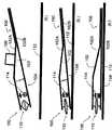
图1以图解的方式显示了一个典型的弹簧鞋底,在踏步之前它的弹簧未被压缩,减震器处于伸展的状态。Figure 1 diagrammatically shows a typical spring sole with the spring uncompressed and the shock absorber extended prior to stepping.
图2显示了一个典型的弹簧鞋底,在踏步时它的弹簧被压缩,减震器也被压缩。Figure 2 shows a typical spring sole with its spring compressed and the shock absorber compressed during stepping.
图3显示了一个典型的弹簧鞋底,当人的体重作用于鞋底时,减震器被全部压缩至能量存储位置。Figure 3 shows a typical spring sole with the shock absorber fully compressed to the energy storage position when a person's weight acts on the sole.
图4显示了一个典型的弹簧鞋底,它的减震器在脚抬起时拖住弹簧以阻止其伸展。Figure 4 shows a typical spring sole with the shock absorber dragging the spring to stop it from extending when the foot is lifted.
图5显示了一个典型的弹簧鞋底,在踏步之前它的弹簧未被压缩,空气减震器处于延展的状态。Figure 5 shows a typical spring sole with the spring uncompressed and the air shock absorber in an extended state before stepping.
图6显示了一个典型的弹簧鞋底,在踏步时它的弹簧被压缩,空气减震器也被压缩。Figure 6 shows a typical spring sole with its spring compressed and the air shock absorber compressed during stepping.
图7显示了一个典型的弹簧鞋底,当人的体重作用于鞋底时,空气减震器被全部压缩至能量存储位置。Figure 7 shows a typical spring sole, with the air shock absorber fully compressed to the energy storage position when a person's weight acts on the sole.
图8显示了一个典型的弹簧鞋底,它的空气减震器在脚抬起后拖住弹簧以阻止其延展。Figure 8 shows a typical spring sole with an air damper that drags the spring to prevent it from extending after the foot is lifted.
图9是一种常规鞋子的曲线示意图:P线是作用于使用者脚上的向上的垂直力,它与使用者的重心相对于足跟的角度有关,在中心处角度为零,角度为负值时为无向前分力、垂直向左的力,角度为正值时为有向前分力、垂直向右的力;Q线是鞋底压缩的程度,它的值与使用者重心相对于鞋跟的角度有关。Figure 9 is a schematic diagram of the curve of a conventional shoe: the P line is the upward vertical force acting on the user's foot, it is related to the angle of the user's center of gravity relative to the heel, the angle is zero at the center, and the angle is negative When the value is positive, it is a force with no forward component and vertical to the left; when the angle is positive, it is a force with a forward component and vertical to the right; the Q line is the degree of compression of the sole, and its value is relative to the user's center of gravity Depends on the angle of the heel.
图10是图1至图8所示鞋子的曲线示意图:X线是作用于使用者脚上的向上的垂直力,它与使用者的重心相对于足跟的角度有关,在中心处角度为零,角度为负值时为无向前分力、垂直向左的力,角度为正值时为有向前分力、垂直向右的力;线V是鞋底压缩的程度,它的值与使用者重心相对于鞋跟的角度有关;线Y是弹簧110的作用力,它与使用者重心相对于鞋跟的角度有关;Z线是与使用者重心相对于鞋跟的角度有关的阻力。Figure 10 is a schematic diagram of the curves of the shoes shown in Figures 1 to 8: the X-line is the upward vertical force acting on the user's foot, which is related to the angle of the user's center of gravity relative to the heel, and the angle is zero at the center , when the angle is negative, there is no forward component force, and the force is vertically to the left; when the angle is positive, it is a force with forward component force, and vertically to the right; the line V is the compression degree of the sole, and its value is related to the use The center of gravity is related to the angle of the heel; the line Y is the active force of the
图11至图16说明了鞋内弹簧可能的布置方案。Figures 11 to 16 illustrate possible arrangements of the inner springs of the shoe.
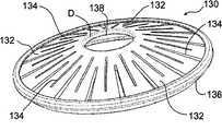
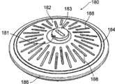
图17至图21说明了一个弹簧110的实施例,该实施例使用了一个拱形构件,这个拱形构件是一个圆锥形的盘,图17是它的顶视图,图18是它的侧面透视图,图19是它的侧视图,图20是横截面图,图21显示的是圆锥盘被压扁的状态。Figures 17 to 21 illustrate an embodiment of a
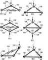
图22至图28依次显示了第一个和第二个使用非圆锥铰链式能量存储和返回装置的实施例。图22至图24依次是第一个实施例的透视图、侧视图和顶视图;图25至28分别是第二个实施例的顶视图、侧视图、端视图和透视图。Figures 22 to 28 show in turn a first and a second embodiment using a non-conical hinged energy storage and return device. 22 to 24 are a perspective view, a side view and a top view of the first embodiment in sequence; FIGS. 25 to 28 are a top view, a side view, an end view and a perspective view of a second embodiment, respectively.
图29至图30依次显示了一个使用了圆锥盘的实施例的透视图和顶视图,该圆锥盘带有集成的弹簧元件。Figures 29 to 30 show in turn a perspective view and a top view of an embodiment using a conical disk with integrated spring elements.
图31至图34依次显示了一个封闭的圆锥盘和环形弹簧的顶视图、侧视图、透视图和断面视图,在环形弹簧上附有一个封闭的底部元件,该元件用来在这个能量存储和返回零件中形成一个气囊。Figures 31 to 34 show, in sequence, top, side, perspective and cross-sectional views of a closed conical disc and ring spring with a closed bottom element attached to it for energy storage and Forms a pocket of air in the return part.
图35显示了一个封闭的圆锥盘切开后的透视图,圆锥盘内有可控制的空气流。Figure 35 shows a cut away perspective view of a closed conical disk with controlled air flow.
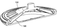
图36显示了一个切开的实施例的特写图,该实施例使用了如图31至图34所示的置于鞋底的盘。Figure 36 shows a close-up view of a cutaway embodiment using the disc placed on the sole of the shoe as shown in Figures 31-34.
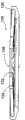
图37显示了该弹簧的一个进一步应用的实例的透视图。Figure 37 shows a perspective view of an example of a further application of the spring.
图38是图37所示的实施例的断面显示图。FIG. 38 is a cross-sectional illustration of the embodiment shown in FIG. 37. FIG.
图39和图40依次显示了图37所示的实例处于零压缩和全压缩的状态。Figures 39 and 40 sequentially show the example shown in Figure 37 in zero compression and full compression.
图41显示了一种带有气囊压缩系统的弹簧鞋。Figure 41 shows a spring shoe with a bladder compression system.
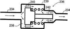
图42显示了一种用于图41所示的弹簧鞋第一个位置的空气转换机构的细节图。Figure 42 shows a detail view of the air switching mechanism for the first position of the spring shoe shown in Figure 41.
图43显示了一种用于图41所示的弹簧鞋第二个位置的空气转换机构的细节图。Figure 43 shows a detail view of the air switching mechanism for the second position of the spring shoe shown in Figure 41.
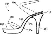
图44显示了一种包含了一个鞋根弹簧的高跟鞋的侧视图。Figure 44 shows a side view of a high heel shoe incorporating a heel spring.
图45和图46依次显示了一种带有凸棱而不是凹槽的圆锥盘的透视图和剖面图。Figures 45 and 46 show in turn a perspective view and a cross-sectional view of a conical disk with ribs instead of grooves.
图47显示了一种带有辐射状的腿或者伸出物的圆锥盘。Figure 47 shows a conical disk with radial legs or protrusions.
图48和图49依次显示了一种带有圆周状槽的圆锥盘的顶视图和透视图。Figures 48 and 49 show, in sequence, a top view and a perspective view of a conical disk with a circumferential groove.
图50至图52依次显示了一种双环弹簧实施例的透视图、侧视图和顶视图。Figures 50-52 show, in sequence, a perspective view, a side view and a top view of an embodiment of a double loop spring.
图53至图55依次显示了一个三圈弹簧的侧视图、透视图以及旋转侧视图,该三圈弹簧的中心圈附件上带有一个铰链。Figures 53 to 55 show in sequence a side view, a perspective view and a rotated side view of a triple coil spring with a hinge attached to the center coil.
图56和图57各自显示了一种圆锥盘弹簧的侧剖视图,这种圆锥盘弹簧内部装有另一个盘作为减震器;图56中的减震盘固定在主盘上,而图57中的减震盘固定在底部的鞋底上。Figures 56 and 57 each show a side sectional view of a conical disk spring with another disk inside as a shock absorber; the shock absorbing disk in Fig. The shock absorbing disc is fixed on the sole at the bottom.
图58显示了一种圆锥盘弹簧剖透视图,在这种盘的内部包含了一个气囊,该气囊是减震系统的一部分;在盘的中心还包含了一个阀门。Figure 58 shows a cut away perspective view of a conical disc spring which contains a bladder inside the disc which is part of the shock absorbing system and a valve in the center of the disc.
图59显示了一种圆锥盘边缘的剖视图,圆锥盘的内部包含了一个气囊,并且盘缘上装有一个自激的密封圈。Figure 59 shows a cross-sectional view of the rim of a conical disk containing an air cell inside and a self-energizing seal on the rim.
图60和图61依次显示了一个圆锥盘的剖面透视图和剖面透视图的特写图,该圆锥盘的内部包含了一个气囊,气囊内的隔膜压缩一种阻尼材料以提供可变的减震率。Figures 60 and 61 show, in turn, a cutaway perspective view and a closeup of a cutaway perspective view of a conical disk containing a bladder within which a diaphragm compresses a damping material to provide a variable rate of shock absorption .
图62显示了一种圆锥盘边缘的剖视图,该圆锥盘的内部包含了一个气囊,并且盘缘上装有一个密封圈,密封力由弹簧环提供。Figure 62 shows a cross-sectional view of the edge of a conical disk, the interior of which contains an air bag, and a sealing ring is installed on the edge of the conical disk, and the sealing force is provided by the spring ring.
图63说明了一种在鞋前脚掌装有弹簧的鞋。Figure 63 illustrates a shoe with a spring in the forefoot.
具体实施方式Detailed ways
图1以图解的形式显示了一种典型的弹簧鞋100。该弹簧鞋100有一个鞋底102,鞋底在此处简要地显示为由上表面102A和下表面102B接合而成;102A可以是一个鞋内底,102B可以是一个鞋的外底。在102A和102B之间有一个中底。鞋底102有一个鞋跟104和鞋前脚掌106。一个鞋帮108固定在鞋底102上。弹簧鞋100可以是任意的人用鞋类,包括但不限于凉鞋、跑步鞋、矫形鞋、各种运动鞋,包括冰鞋、滑板鞋、滑雪靴、步行鞋或步行靴、登山鞋或登山靴,以及正装鞋、靴、高跟鞋、人字拖鞋或夹趾拖鞋、普通拖鞋、平底鞋、木屐和工作靴。鞋帮108一般至少要包括能将人的足部固定于鞋跟102上的方法,可以是各种固定的方式中的一种,如使用一根或多根弹性带、有搭扣或其它钮扣的带子、鞋带或者是弹性套。Figure 1 shows a
鞋底102上安装了一根弹簧110。弹簧110简要地显示在图1中,其精确结构无需说明。此处显示的结构旨在演示一个所需特性的弹簧的实施例。在一种鞋中可以使用多个弹簧110。弹簧110可能是一种复式弹簧,也可能包括鞋底的零件。弹簧110应以一种合适的方式固定于鞋底102上。A
图1所示的鞋100置于地面112上,此时的弹簧110处于零压缩状态,内鞋底102A和外鞋底102B相隔的距离为A。在图2中,弹簧鞋100和弹簧100被完全压缩,此时内鞋底102A和外鞋底102B相隔的距离为B。弹簧在相当于全压缩和无压缩状态的两个终结点之间的行程范围就等于A-B。弹簧110的弹簧刚度系数随着鞋底102的压缩而变化,从而提供了一个还原力,当鞋跟102被压缩时,这个还原力能够至少阻止弹簧行程范围内的部分压缩。由参考文件可知,弹簧刚度系数是联系作用于弹簧110上的力及弹簧位移的一个系数。许多弹簧的刚度系数是常值,但在此处所用弹簧的刚度系数是变化的。当弹簧鞋100平置于地面并承受全部或部分使用者的重量时(如图3所示),鞋底102被压缩,一部分弹簧行程范围提供的还原力允许能量被无限期地存储;当全部或部分使用者的重量不再压缩弹簧时,能量被返回给使用者(如图4所示)。The
因此,当使用者的重心位于使用者的脚跟之前时(使用者向前行进),这种典型的弹簧鞋100就可以将部分压缩能返回给使用者。弹簧110可由一个刚性构件和一个可延性构件组成,当刚性构件在足部的挤压下移动时,可延性构件将被拉伸。在弹簧110的某些实施例中,由于配件(或鞋底)被压紧时产生的全部或部分压缩位移,拉伸可延性构件的主要的力的方向变得与可延性构件延伸的方向更加一致。在弹簧110的某些实施例中,由于配件或鞋底被压紧而产生的全部或部分压缩位移,刚性构件的机械效率随着它拉伸可延性构件或压紧受压构件而提高。Thus, when the user's center of gravity is forward of the user's heel (the user is moving forward), the
当弹簧110受到外力,如受到使用者的体重(及惯性)压缩时,弹簧将产生一个振荡频率,该频率部分取决于所受的外力。如果作用力小于将弹簧110压缩至弹簧刚度为零的点所需的力,弹簧110将会产生一个比较常规的振荡频率。然而,当施加的重量足够将弹簧110压缩至力减弱区,弹簧将不会振动直到压迫鞋底的力减小到使弹簧离开该区域。When the
由于弹簧的力随着鞋底102的压缩而减小,需要使用两个不同的零件,弹簧110用于能量存储,减震器114用于能量损耗。作为能量存储和返回装置的弹簧110可由多种零件制成,可包括多个弹簧原件。弹簧110被置于鞋底102内鞋跟下的位置,当它产生了部分或全部压缩位移时,弹簧内会产生一个还原弹力。在某些实施例中,一个或多个弹簧110可能被安装在鞋前脚掌106内。在压缩过程中,弹簧110在被部分压缩时施加的垂直力比它被全部或近似全部压缩时的垂直力要大。在力的最大值出现的位置(大约在整个压缩位移或行程范围的三分之二处,但是也可能是压缩过程中的其它点),弹簧110施加的垂直力可达到使用者全部体重的50%至80%之间。在力的最大值出现的位置,弹簧的刚度系数为零。当弹簧被全部压缩时,该零件最大的力约为使用者重量的20%至40%之间。对于获得良好性能来说,以上比例无需要求精确,并且通过测试已经发现一根弹簧就能为很大体重范围内的使用者提供良好的性能。对于一种步行鞋来说,这是能最大化地返回能量更适宜的力。特制的跑鞋更愿意有较高的能量返回比例,而对于某些只要求提供较少的能量返回功能的低性能鞋可能会愿意这个比例较低,比如某种较便宜的鞋。在某些应用中可能更希望最大的压缩力能高于60%,全压缩力低于30%。在某些应用中可能更希望最大的压缩力能低于60%,全压缩力高于30%。Since the force of the spring decreases as the sole 102 is compressed, two different parts need to be used, the
上一段中所述的使用者体重的较好的比例是对于步行鞋来说的较好的比例。最大弹力和全压缩弹力在同一个提供弹力的装置中也可能有不同的变化,弹力在第一部分压缩位移中增加然后在接下来的压缩中减小。在全压缩时,弹簧110也可能(独自或与一个或多个构件联合)再次提供一个增加的弹力。这种情况可能发生在相对较短的压缩位移内并且起到一个“底部缓冲器”的作用,以阻止全压缩时的有害冲击。The good proportions of the user's body weight described in the previous paragraph are good proportions for walking shoes. The maximum spring force and full compression spring force may also vary differently in the same device providing spring force, the spring force increases during the first part of the compression displacement and then decreases during the subsequent compression. At full compression, the
此处列举了一些弹簧110的结构方式进行描述。如果单独使用弹簧110,将它压过最大力出现位置所需的力大约为使用者体重的60%,略大于使用者站立时将其全部体重平均分配至双足的情况。弹簧110被全部压缩时所受的力可能会比这个比例的使用者体重更大或者更小,但发明者相信,对于步行鞋来说,使用者体重的60%左右是本零件在最大压缩位置理想的弹簧力。弹簧110在全压缩(偏指行程范围在5mm到20mm之内的情况,但压缩行程不在此范围内的弹簧也可在某些实施例中使用)时的弹力为使用者体重的30%左右为宜。Some structures of the
弹簧110的作用是允许鞋底102在每一步的踏步(脚与地面最初的接触)阶段能够全部压缩或近似全部压缩,并且在足跟开始卸力并抬起之前,弹簧110始终保持压缩状态直到使用者的重心位置超过或几乎超过了使用者的脚跟和/或脚踝的位置。随着使用者开始减轻压在脚跟(图4)上的重量,脚跟也不再提供用来保持弹簧处于全压缩状态的力,同时随着弹簧垂直伸展回其原有形状,一部分储存在弹簧110中的能量就被返回给使用者。由于此时使用者的重心在使用者的脚跟和/或脚踝前面,作用在使用者脚跟上的垂直力将会导致一个向前的分力,因此能够向前推动使用者。The function of the
在某些实施例中使用了一个减震器114,它起到一种能量损耗材料的作用,可以由一个或多个元件制成。减震器114也被安装在鞋底102的鞋跟104上,位于脚跟的下面(在某些实施例中也可能单独或同时安装在鞋前足掌的下面)。减震器114被设计用来对鞋底102由使用者的部分重量和未被能量储存和返回弹簧110有效反弹的惯性引起的压缩提供阻力。减震器114是有偏向性的,因此它仅仅或者主要是在鞋底压缩阶段和反弹阶段中的压缩阶段起作用。在反弹阶段,弹簧110和减震器114的结合体允许减震器缓慢地返回到它本来的形状,返回的速度必须快到能使它在下一次踏步的过程中耗散能量,但是也不能与使用者抬起脚跟时弹簧伸展的速度一样快。In some embodiments a
这种功能是可以实现的,例如通过使用美国俄亥俄州肯特Sorbothane公司制造的SorbothaneTM材料来实现的话,仅需将SorbothaneTM材料做成的抗压元件的顶部或底部永久地连结在鞋底102(或弹簧)上即可。在鞋底102的全部或部分压缩阶段,减震器114的另一端与鞋底102接触,但是在鞋底102的伸展阶段可以允许其不接触鞋底,这样弹簧110返回给使用者的能量就不会被减震器损耗。This function can be realized, for example, by using Sorbothane™ material manufactured by Sorbothane Company, Kent, Ohio, USA, only by permanently attaching the top or bottom of the compression member made of Sorbothane™ material to the sole 102 (or spring) on it. The other end of the
这样,在踏步阶段弹簧110和减震器114就像常规的线性刚度弹簧或能够减速使用者的全部重量而不是突然降至最低点的刚度递增弹簧一样,将会被以一个相似的力的增量压缩。常规刚度系数弹簧在使用者的重心位置超过使用者的足跟之前就会返回一大部分的这种压缩能(通过弹簧的再次伸展)。然而在鞋100中,减震器114并未增加反弹的能量(或频率),因为它仅能显著地起到减慢压缩作用。Thus, during the stepping phase, the
这样做的效果是能储存很大一部分的步行能量到弹簧110中,并且用减震器114提供一个合适的减速率,然后当使用者的重心位置超过或几乎要超过使用者的脚跟时,就将储存在弹簧110中的能量返回给使用者。换句话说,这些材料的结合效果能让使用者感觉到两个元件(弹簧110和减震器114)在共同作用,它们提供了足够的压缩力和/或阻力以逐渐在每一步的踏步阶段内缓冲使用者的重量。The effect of doing like this is that a large part of walking energy can be stored in the
如图4所示,当使用者的重心位置移动到或几乎移动到使用者的脚跟之前,并且使用者开始从他们的脚跟卸力时,储存在弹簧110中的能量被以一个作用于脚跟上的向上的力的形式返回,这个向上的力能帮助使用者前进。减震器114在鞋底伸展的全部或部分过程中未与鞋底接触(或未明显地阻碍鞋底的伸展),也未明显阻碍弹簧110的伸展。如果减震器114是一种固体构件,比如一种由SorbothaneTM材料(或其它能量损耗材料或材料配置)制成的元件,它应该伸展得比弹簧110更慢但是又要快到能够回复形状(或位移)以使这个或这些元件在能够下一次踏步中耗散能量。As shown in FIG. 4, when the user's center of gravity moves to or nearly in front of the user's heel, and the user begins to unload force from their heel, the energy stored in the
图5至图8所示为另外一种高能量耗散的减震器114的实施例。图5至图8所示的实施例使用了由一种柔韧但不可伸展的材料做成的空气隔膜116,隔膜116上带有一个阀门装置118,该气阀装置能迫使空气在受压缩时从一个限流孔通过,并且通过打开一个更小的单向限流阀允许空气返回到隔膜中以使隔膜重新膨胀。阀门装置118的简化装置仅使用了一个双向的限流孔,这个双向的限流孔应小到能够在隔膜受压紧缩的过程中提供足够的能量耗散,同时又要大到能够允许空气隔膜在两次踏步之间完成重新膨胀。5-8 illustrate another embodiment of a high energy
在图5至图8所示的结构中,空气隔膜116在膨胀过程中应该能与弹簧10失去接触,如图8所示,或者是虽然保持接触但是它的变形不会明显地阻碍弹簧10的伸展。In the configuration shown in FIGS. 5 to 8, the
图58显示了一个位于圆锥盘顶部的小孔308和一个主要起消声作用的多孔材料限制元件304。小孔应足够大,以使圆锥盘内封闭的气囊重新膨胀时所受的限制最小。同时小孔也应该足够小,以防止在压缩过程中可压缩的泡沫构件306被挤出小孔。或者,小孔的开口可以更大并且用不可压缩的多孔材料填充以阻止可压缩的泡沫材料被挤压变形。该实施例也显示了一个未被标记的圆形凸起,它位于底部密封构件的外面,用于安装盘底。Figure 58 shows an
在压缩过程中,主要由附着在气囊底部的可压缩泡沫构件306对压缩进行限制。该构件更适宜使用开孔型泡沫,但是如果它有一个透气的顶面的话也可以使用封闭孔型泡沫(也可使用一种带有透气的顶面的开孔型泡沫,其长期功能可能更好)。泡沫材料随着压缩而变得更稠密,对气流的阻力也随之增加。如果是封闭孔型泡沫的话,顶面与小孔区域的接触压力随着压缩而增加,同时透气的顶层对气流的阻力增加。不管是使用哪种材料,气流的阻力都随着盘的压缩而增加,从而提供了一个逐渐增加的压缩衰减效果。During compression, the compression is limited primarily by the
可压缩的泡沫体306适宜使用一种带有黏弹性的开孔型结构,这种特性可以使泡沫在圆锥盘伸展时还可以保持短暂的压缩状态。这样在弹簧伸展的过程中,气流的限制被最小化,阻尼仅偏压于弹簧的压缩上。在下一次踏步之前,泡沫应能尽快地膨胀以回复它的原有形状。The
小孔308也可设置在底部密封构件上(贯穿于本次公开中使用的顶部和底部的概念均与弹簧本身相关,这仅是为了便于讨论,在鞋子中该盘可能被倒置使用),而泡沫附着在圆锥盘上。具有记忆功能的泡沫最初可以与小孔接触或不与小孔接触(如图58所示)。鞋的内底必须设置得允许气流进出圆锥盘。这种气流可能对鞋的通气有额外的作用。The
该偏压空气阻尼器的另外一种设计方案如图60至图61所示,它将一层阻尼材料316夹在隔膜314和底部密封构件186之间,起到流量调节元件的作用,因此当气囊内的压强较高时,气囊挤压阻尼材料以限制气流穿过阻尼材料流出气囊。当空气流向其它方向时,由于阻尼材料未被压缩,气流受到的限制较小;在阻尼材料和底部密封构件之间或是阻尼材料和隔膜之间可能会有一个缺口,这取决于实施例的设计需要。阻尼材料可能是一种开孔型泡沫、毛毡或是其它透气的材料。韧性的隔膜密封圈可能是聚氨酯,但是也可以使用很多其它材料。Another design of the biased air damper is shown in Figures 60-61, which sandwiches a layer of damping material 316 between the diaphragm 314 and the
该阻尼器结构集成了一个单向密封圈,通过压力调制空气阻尼的方式如下:当盘被挤压时,增强的空气压力作用于韧性隔膜314上,随着空气通过阻尼材料从隔膜孔或孔群318流向底部密封孔或孔群320,在高速压缩的过程中增强的气压压缩阻尼器316,产生一个增大的空气阻尼。随着压缩变缓至接近全压缩时,空气压力也会随着使用者的重量被缓冲而减小。这使得阻尼器不被挤压从而减小气流的阻力,于是空气就可以在全压缩状态时被排出而不产生一种气垫的效果,在尽可能小地产生反弹的情况下,使用者的重量向下完全停止。随着圆锥盘的反弹,韧性隔膜314抬起以使得空气能自由流入气囊。阻尼器316上可以任意设计一个小洞以允许空气在弹簧伸展期间可以不受限制地流入,这个小洞最好是与隔膜314上的孔或孔群同轴,或与底部密封构件186上的孔或孔群同轴。The damper structure incorporates a one-way seal that modulates air damping by pressure in the following manner: As the disk is squeezed, increased air pressure acts on the flexible diaphragm 314, as air passes through the damping material from the diaphragm holes or holes Group 318 flows to the bottom seal hole or hole group 320, and the increased air pressure compresses damper 316 during high speed compression, creating an increased air damping. As the compression slows to near full compression, the air pressure also decreases as the weight of the user is cushioned. This keeps the damper from being squeezed and reduces airflow resistance, so air can be expelled at full compression without creating an air cushion effect, with as little bounce as possible, reducing the weight of the user down to a full stop. As the cone rebounds, the flexible diaphragm 314 lifts to allow air to flow freely into the bladder. The damper 316 can optionally be provided with a small hole to allow unrestricted inflow of air during spring extension, preferably coaxial with the hole or hole group on the diaphragm 314, or with the hole on the
使用一个可压缩二级密封或气流阻力构件322可以进一步增加空气的阻力,甚至在接近全压缩时完全将气囊密封以减小全压缩时的运动冲击。The use of a compressible secondary seal or airflow resistance member 322 can further increase air resistance and even completely seal the airbag at near full compression to reduce the impact of movement at full compression.
图9和图10所示的曲线图对比说明了常规的鞋底和使用了本发明的鞋底的能量存储和消散情况。简笔画显示了重心的位置COG和脚踝的位置H。每一个简笔画被放置在穿过它在X轴上位置的垂线上,与简笔画中所示的每一步的位置中重心相对于脚踝的角度相一致。四幅简笔画对应了图1至图4所示的四个位置。图9中的阴影区域R表示常规的弹簧鞋能返回给使用者的能量。图10中的阴影区域W表示使用了弹簧的鞋110能返回给使用者的能量。阴影区域W在重心相对于脚踝的角度大于零的步行阶段内起作用,此时弹簧110产生了一个垂直力,这个垂直力在使用者重心上有一个向前的分力。The graphs shown in Figures 9 and 10 illustrate comparatively the energy storage and dissipation of a conventional shoe sole and a shoe sole using the present invention. The stick figure shows the location COG of the center of gravity and the location H of the ankle. Each stick figure is placed on a vertical line through its position on the x-axis, corresponding to the angle of the center of gravity relative to the ankle for each step shown in the stick figure. The four stick figures correspond to the four positions shown in Figures 1 to 4. The shaded area R in Figure 9 represents the energy that a conventional spring shoe can return to the user. The shaded area W in FIG. 10 represents the energy that the
图11至图16说明了弹簧110的一些实施例,这些实施例使用了刚性构件122和弹性弹簧元件124和126。弹性弹簧元件124的拉力阻碍刚性构件122变平。弹性弹簧元件126通过它的压缩阻碍刚性构件122变平。在这两种方式中,刚性元件122都是在施加在弹簧110的顶点C上的压力作用下变平的。随着刚性元件122变平,它们在元件124和126上施加了一个递增的高机械效益,随着弹簧力达到最大的值然后开始降低,弹簧110的刚度系数先降为零然后变为负值。FIGS. 11-16 illustrate some embodiments of the
刚性构件122、弹簧元件124及弹簧元件126各自通过铰链或枢轴联结。刚性构件122的刚度应足够大,以使一根或多根弹簧伸展而又不会变形到被压弯或产生破坏。铰接元件的摩擦能帮助缓冲。如果使用的是活动铰链,所有铰链的固有刚度系数都会影响弹簧的总体刚度系数。铰链元件也需有足够的韧性以防止铰接元件的弹力使弹簧110的能量存储和返回功能失效。说得更清楚些就是,铰链在枢轴上转动或弯曲的时候受到的阻力应小于整个弹簧组件减小的力。否则组件就不能提供一个渐减的弹簧力。
图17至图21说明了几个弹簧110的实施例,这些实施例使用了一个拱状元件,即圆锥盘130。圆锥盘按照图11所示的设计原理来运作。在本文中拱状的意思是指中心处被抬高。圆锥盘130的边132的刚度必须足够高,以免当它们在弹簧压缩承受压缩载荷时被压弯或是发生机械失效,盘边上还有扩展槽134,在本实施例中扩展槽是放射状地分布的。FIGS. 17 to 21 illustrate
扩展槽134可能是盲槽(未穿透圆锥盘)或可能穿透了圆锥盘130。圆锥盘130的边缘连接了一个弹性元件136用来阻挡圆锥盘130在受到尖端D的压力时变平。圆锥盘130和边缘的环136组成了一个弹力先渐增后渐减的弹簧110的实施例。换句话说,圆锥盘130和环136在弹簧未被全部压缩时比被全部或几乎全部压缩时施加的力更大。施加在压缩上的力不必遵循同样的曲线;比如说,它可能是一个近似的常数直到弹簧伸展到某个点后开始减小,或者甚至是在整个伸展过程中一直减小。如果圆锥盘130包含的第一种材料具有第一种弹性,则扩展槽包含的第二种材料的弹性应大于第一种材料(比如说第二种材料可以是人造橡胶、某种流体或是空气)。弹性构件136同时也构成了圆锥盘130的底座。
圆锥盘130加环136就是一个能量存储和返回元件典型的实施例。其它的一些结构也是可行的。扩展槽134允许圆锥盘130在圆周上伸展而几乎对圆锥盘130的材料不产生压力。如果不组装外环136,要压扁圆锥盘130所需的力要比组装了外环136时小得多。圆锥盘130可能由聚丙烯或是其它负泊松比的材料制成,或是由其它合适的材料如金属或塑料制成。
如果圆锥盘130由金属材料或刚性塑料制成,就是说不是由聚丙烯或是其它负泊松比的材料制成,扩展槽在内部的棱138上可能需要设计一些延长部分E,以使得在被压扁时圆锥盘130的材料不会受到破坏。圆锥盘130的内部棱138构成了一个环形铰链,圆锥盘130的边132围绕着铰链弯曲。如果使用的是一种负泊松比的材料比如聚丙烯,但是不限于聚丙烯,可以不设伸向中心的扩展槽,因为在应变较高的区域它可以起到像活动铰链一样的作用。在某些实施例中,伸向中心的扩展槽可能会与故意留下的裂缝线或球以及枢轴轴承相连,以防止内环在弹簧压缩的过程中围拢或是半径减小。If the
当圆锥盘130被施加于顶点D的垂直压缩力压扁时,能量随着环136的径向和周向拉伸而被存储在外环136中。随着圆锥盘的压扁,盘在外环上的机械效益显著增加,并且作用在圆锥盘上的垂直力开始减小。外环可以由塑料制成,比如聚碳酸酯或是由Dupon公司生产的DelrinTM高性能聚甲醛树脂共聚物或均聚物,这些材料具有很高的延伸特性和疲劳寿命。When the
对于一个供体重100kg的人使用的圆锥盘130来说,只需使用如下的尺寸、材料和弹簧刚度系数即可:最大受力时垂直位置7mm、在最大垂直位移上的最大受力60kg、总最大垂直位移10mm、在总最大垂直位移时的受力30kg、组件外径75mm。圆锥盘130可以包含一个减震器114(图17至图21中未显示),但是包含的也可能是一个能够自我膨胀的空气隔膜116,根据图5到图8所示,空气隔膜上有一个用于缓冲压缩的限流孔和一个高流动性的单向阀以允许它在重新填充的时候受到较小的气流限制。For a
该空气隔膜116可能在圆锥盘组件的内部,或者是一种包围着圆锥盘组件外围的螺旋管的形状,或者可能是包围着圆盘的一个气囊,又或者最好是如如图32至图36所示的一个集成在弹簧110本身结构中的气囊。这些示例图中的结构适宜于将步行鞋返回的能量最大化。在压缩力更大的跑鞋中使用的力可能要更大。在低性能鞋中使用的力可能更小,此时弹簧110包括了其它的鞋底元件,如一个或多个泡沫弹簧(比如说圆锥盘被装入常规的鞋用泡沫材料或被常规的鞋用泡沫材料包围,或是与一个空气弹簧相连)以使得弹簧110返回一个更低比例的踏步压力。The
在其它实施例中,使用了一个或多个额外的盘来提供缓冲力。第二个盘可以如图56所示的那样固定在主盘上,也可以如图57所示的那样固定在底座上。减震盘300宜用具有高黏弹性的材料制成,比如聚氨酯。这将使得减震盘施加的力在压缩时比伸展时要大。理想状态下,第二个盘在主盘行程上某个点开始压缩,主盘的力在该点处开始减小。这使得在弹簧行程中弹力渐增的距离更长。主盘可以使用本专利描述包含的任何一种设计。减震盘也可以使用本专利描述中的任何一种设计,其主要特性在于它最好(但非必须)是一种黏弹性比主盘更高的材料,且其行程比主盘更短,在主盘的压缩过程中它就开始压缩。如图57所示,在某些实施例中可以选择性地在减震盘上设计向内或向下突出的法兰盘302,起到全停减震器的作用。In other embodiments, one or more additional discs are used to provide cushioning force. The second tray can be attached to the main tray as shown in Figure 56, or to the base as shown in Figure 57. The damping
圆锥盘130的其它益处还包括它的横向稳定性。虽然圆锥盘130允许有高行程,但它只允许鞋底102在一个明确的垂直运动中压缩。为了使它起作用,需要将圆锥盘130固定到上表面102A和下表面102B上以防止它发生侧移。圆锥盘130也可以前后左右调整(比如使用一个偏心凸轮)以对盘的正放或者反放进行位置补偿,或者是对鞋跟下的盘的前后位置进行调整。圆锥盘的一些其它的结构方案、材料组合和几何尺寸也是可行的。Other benefits of the
位于上下鞋底之间的圆盘可能被一个弹性密封圈包围以防止泥土等物进入盘内。密封圈可以使用一种非常轻的泡沫,或是一层由弹性固体材料或泡沫材料制成的弹性薄膜或气囊完全将盘包围来实现。理想状态下这种密封材料不会显著地增加鞋底的弹簧刚度系数。The disc located between the upper and lower soles may be surrounded by an elastic seal to prevent dirt etc. from entering the disc. The seal can be achieved using a very light foam, or a flexible membrane or bladder made of a resilient solid or foam material that completely surrounds the disc. Ideally this sealing material would not significantly increase the spring rate of the sole.
图22至图25显示了一个拱状的非圆锥铰链式弹簧140作为弹簧110的一个实施例。这个实施例使用了一个或者多个顶部铰接式刚性构件142和/或一个或多个底部铰接式构件143来拉伸一个最好是使用DelrinTM聚甲醛树脂(但也可使用其它一些材料)制成的弹性构件144。弹性构件144可能环绕在如图22至图24所示的组件的外部。图22中使用的铰链可能是一个由一个或多个铰链组成的复合铰链。22 to 25 show an arched
图25至图28显示了一个拱状的非圆锥形铰接式弹簧150作为一个带有内部弹性构件的弹簧110的例子。这个实施例使用了一个或多个顶部铰接式刚性构件152和/或一个或多个底部铰接式构件153来拉伸一个或多个最好是使用DelrinTM聚甲醛树脂(但也可使用其它一些材料)制成的弹性构件154。弹性构件154可能部分在内部分在外。图22至图28中的刚性边142和152被铰接到图22中构件的顶端F和G。使用图22至28中的拱形弹簧140和150的优点在于整个组件的高度可以降低以得到一个很低的轮廓。比如说,如果图22至图28中的弹簧和铰链构件厚3mm,伸展的高度为18mm,则压缩比就会达到很高的6:1。使用的铰链可能是由一个或多个铰链组成的复合铰链。图22至图28中未显示缓冲的方法,但是许多单向能量消散方法或如前所述的减震器114都可以与这些能量储存和返回方法结合使用。Figures 25 to 28 show an arched non-conical hinged
图29和图30显示了一个集成了圆锥盘160和环164的弹簧110的进一步简化的实施例。图29所示的实施例使用了一个圆锥盘162和一个集成的外环弹簧164。这两个元件可以使用同样的材料作为一个工件来注塑成形,最好是选用DelrinTM但是许多其它材料都可替代使用。多种材料的组合也可以在两极或多极注射成型工艺中使用。本实施例的优点在于结构简单和成本低。图30中的圆锥盘172是盘162不带完整边缘的截面图。29 and 30 show a further simplified embodiment of the
本实施例的重要特征包括但不仅限于如下几点:如果圆锥盘构件172与图30中所示的完整的外部环弹簧164分离,此时将圆锥盘压缩成一个平面或近似平面的形状所施加的力要比压扁同样的尺寸、同样的材料制成,但没有设置槽和/或凹坑的圆锥盘施加的力小。这是因为放射状的隔断174允许圆锥盘在被压缩时周向伸展。Important features of this embodiment include, but are not limited to, the following: If the
这样,随着圆锥盘162被压缩,就导致未被隔断的外环弹簧部分164在径向和周向拉伸,于是环弹簧164储存的全部施加到圆锥盘162顶部的能量比圆锥盘162未被隔断的情况要多,这能帮助弹簧在压缩的某个位置得到一个渐减的弹簧力。另外一种重要的特性是在圆锥盘162附近(如果如图29和图30所示,圆锥盘162有一个中心孔,则是与内径相邻的区域)必需能允许或能够产生高水平的应变。该区域受到较高的压缩力和较高的弯曲载荷,因而必须由聚丙烯或是不限于聚丙烯的其它负泊松比材料制成,或者它必须有裂缝、槽或不完全的球形连接以阻止压缩位移但是又允许高的弯曲载荷和/或位移。一种二极模塑造型工艺适用于此处的整体盘结构,该工艺允许内径大应变区域由聚丙烯但不限于聚丙烯的材料制成,外环弹簧区域用DelrinTM材料但不限于DelrinTM材料制成。Like this, along with the conical disk 162 is compressed, just cause the outer ring spring portion 164 that is not cut off to be stretched radially and circumferentially, so the energy that the whole that ring spring 164 stores is applied to the top of the conical disk 162 is less than that of the conical disk 162. The situation of being cut off is more, which can help the spring to obtain a gradual spring force at a certain position of compression. Another important characteristic is that the vicinity of the conical disk 162 (if the conical disk 162 has a central hole as shown in Figures 29 and 30, it is the area adjacent to the inner diameter) must allow or be able to generate high levels of strain . This area is subject to higher compressive forces and higher bending loads and must be made of polypropylene or other negative Poisson's ratio material not limited to polypropylene, or it must have cracks, grooves, or incomplete spherical connections to Resists compressive displacement but allows high bending loads and/or displacements. A two-pole molding process is available for the integral disc structure here, which allows the inner diameter high strain region to be made of polypropylene but notlimited to polypropylene and the outer ring spring region to be made of but not limited to DelrinTM material.
图31至图34显示了一个能量储存和返回弹簧180,它使用了封闭的圆锥盘182和环弹簧184,连同密封底部元件186一起在能量储存和返回弹簧180的内部形成一个气囊185。气囊185用来在踏步过程中随着使用者的重量和惯性被减速而损耗部分的压缩能。圆锥盘182的一个重要特性是它在辐状压缩时是相对刚性的,但在周向压缩时是相对弹性的,以便圆锥盘182在没有安装环弹簧184的情况下可以被比在圆锥盘182外缘上安装了环弹簧时小得多的力压平。环弹簧184可以被机械地固定在圆锥盘182的外缘上和/或使用二极模塑造型工艺塑造在圆锥盘上。在本实施例中,随着圆锥盘182的压缩,外环弹簧184伸展并从底部扭转或呈喇叭形展开出来。这比滑动和枢轴运动更为有利,因为摩擦力的减小可以增加组件的能量存储和返回能力。底部构件186可以由一种刚性氨基钾酸酯材料制成,当然也可以使用一些其它材料。底部构件186将环弹簧184密封起来以构成气囊185。底部构件186也可以通过使用一个偏心定位器183来协助固定盘180提供稳固的位置。Figures 31 to 34 show an energy storage and
图59显示了一个位于圆锥盘130和底部构件186之间的自激密封圈310,由圆锥盘和底部构件形成的气囊内的空气压力作用在密封圈上以增强密封力。在本实施例中使用了一个刚性扣环312来防止底部密封元件186在受到空气压力时扩张。Figure 59 shows a self-energizing
图62显示了一个实施例,其中位于底部密封元件186和圆锥盘130中间的密封圈被环弹簧184提供的力保持在底部密封元件上。底部密封元件可能包含一个伸展元件324以使得密封圈在圆锥盘被压平时更易伸展。FIG. 62 shows an embodiment in which the seal ring intermediate the
当圆锥盘182与环弹簧184组装在一起时,需要用来将压缩圆锥盘182压至全压缩或近似全压缩状态的压力的理想值大约在压缩圆锥盘的最大压力的10%至50%之间。理想状态下,圆锥盘182和弹簧184的构造使得圆锥盘182在全压缩时近似被压平。这使得盘弹簧184不用施加一个穿过圆锥盘182的显著的垂直力就可以得到最大的延伸。垂直力更加合适,但是圆锥盘构件182提供的垂直力会抵抗被压平。虽然也可以使用其它的一些材料,但是对于圆锥盘182来说聚丙烯或是其它负泊松比材料更合适,因为这种材料能使大应变区域变成活动铰链。放射状的槽188或其它允许周向伸展的形状(未显示)被设计成大应变区,大应变区允许圆锥盘构件182从圆锥形变形到一个更平的形状。When the
通过使用盲槽188(从顶部,如188A所示,或从底部,或从顶部和底部)而不是通槽,当圆锥盘182压缩时,它与环弹簧184以及可能存在的单独基座构件186一起能够提供一个密封的气囊185。槽188也可以在盘182内部通过一层薄膜来密封。在压缩期间,密封的气囊185内的空气被压缩,压力升高,然后被迫通过一个限流装置,比如但不仅限于,一个或多个限流孔187,或一层多孔材料(未显示)。这就提供了一种紧凑、轻便的方法来消散一部分的压缩能量。在全压缩状态下,气囊185中的大部分空气将通过限流装置187排出,因此踏步的冲击将会被吸收。By using blind slots 188 (from the top, as shown at 188A, or from the bottom, or both) instead of through slots, when the
一旦使用者的重量被盘的弹力和空气排出气囊的缓冲力一起减速,空气(指现在从气囊中被排出的空气)将不能再对盘作用于使用者脚上的垂直力作出贡献。这就使得盘182保持被压缩的状态直到使用者卸载他的鞋跟(随着重心的位置移至脚踝的前面),然后盘182将会垂直伸展并推动使用者前进。随着盘182伸展到它本来的形状,底座构件186上一个或多个装了阀门的气流开口189允许空气不受限制地重新进入气囊,开口189的弹性单向阀门构件189A安装在底座构件186上。Once the user's weight is decelerated by the spring force of the disc together with the cushioning force of the air expelled from the air cell, the air (meaning the air now expelled from the air cell) can no longer contribute to the vertical force of the disc on the user's foot. This allows the
开口189在盘182收缩的过程中被弹性单向阀构件189A密封。在盘扩张的过程中,某些实施例可能要求对穿过开口189的气流进行一些限制,以此来稍微减缓能量的返回。区域189B可以通过焊接或胶合作为连结点托住位于圆锥盘180的底部构件186中的密封圈189A。
这个实施例的其它可能特征包括一个位于圆锥盘顶部和底部的偏心定位器183,这个定位器有一个带有止动位置调整系统(使用一个弹性突出物181作为止动器)以允许圆锥盘182被精确地左右调整来补偿圆锥盘的正放或反放。底部构件上的定位偏心盘183可能也有一个允许圆锥盘被移开或插入(通过将圆锥盘转至非止动位置)但是在止动位置能牢固地支承圆锥盘的速释啮合系统。阀门流量可调节的开口189和限流器187也可以用来控制缓冲气囊185内外的气流。Other possible features of this embodiment include an
从密封的圆锥盘182的气囊中流出的气流可以由电脑控制的阀门根据不同的使用者和不同的地形来进行调整。图35显示了一个简单但有效的自我调节气流阻尼系统。密封的圆锥盘192的构造方法类似于图31至图34所示的圆锥盘182。密封的圆锥盘192使用了一种可压缩的多孔材料191作为流出气囊195并穿过孔197和/或一个或多个刚性多孔材料构件191的空气的预阻尼构件,这种材料可以是但并不局限于一种开孔型聚氨酯泡沫。在圆锥盘压缩过程中,这种可压缩材料191对穿过它的气流的阻力随着它被压缩而递增,因此能量损耗(缓冲效果)随着盘192接近全压缩状态而增加。The airflow flowing out from the air bag of the sealed
由于这种气流缓冲系统的特点,可以预计不管使用者是在散步(低速/小冲击的踏步)还是跑步(高速/大冲击的踏步),只要对相同的结构进行调整就可以充分地缓冲使用者的踏步。Due to the characteristics of this airflow cushioning system, it can be expected that whether the user is walking (low-speed/small-impact stepping) or running (high-speed/high-impact stepping), the same structure can be adjusted to sufficiently cushion the user stepping.
图36显示了一个图31至图34所示的带有止动器181的弹簧实施例180;止动器被牢固地安装在相邻的几个凹槽197A中的一个;凹槽197A位于鞋底上部198A的支撑部件196A上。圆头193可以旋入鞋底下部198B的支撑部件196B上的槽197B中,止动器181在鞋底内支撑弹簧180,鞋底可能是图1至图4所示的某个鞋底102。图36也显示了一个圆形间隙199,它的材料与盘182的材料相同,作用是在盘182的高应变区域提供一个放射状的活动铰链。Figure 36 shows a
图38至图40显示了弹簧110更进一步的实施例。在图37中,刚性平板构件202铰接在位置203处,它的内部固定在一个随着构件202被压缩而伸展的弹性构件204上。平板构件202形成了一个穹顶,在本例中它的形状像一个屋脊。把手206可以用来适当地支撑弹簧元件204。图38是图37所示实施例的剖视图,用来显示把手206。图39显示的是图37所示实施例处于零压缩状态,而图40显示的是图37所示的实施例处于全压缩状态。38 to 40 show further embodiments of the
就图37中所示的屋脊状的刚性元件来说,与弹性元件204最近的外部铰链203的铰轴非常近似同轴并且邻近弹簧的平面中心,以避免弹簧的某条边压倒其它的边而产生扣紧效应。In the case of the ridge-like rigid member shown in FIG. 37, the hinge axis of the outer hinge 203 closest to the
在更进一步的实施例中,弹簧10是用一个空气隔膜系统形成的。图41至图43说明了鞋211中一个空气隔膜系统210的实施例。鞋211包括鞋底212和鞋帮214。在鞋底212内部,空气隔膜或气囊220与储存器222通过一根第一导管224和一根溢流管234相连。一个单向阀226位于管224内,一个单向阀236位于在溢流管234内。导管224和234也可以用内置了两个阀门226和236的一根导管来代替。储存器222,导管224、234,以及阀226、236被集成在鞋211中,比如说置于鞋帮214内。使用的两个单向阀也可由一个双向阀代替。In a further embodiment, the spring 10 is formed using an air diaphragm system. 41 to 43 illustrate an embodiment of an air membrane system 210 in a shoe 211 . The shoe 211 includes a sole 212 and an upper 214 . Inside the sole 212 , the air membrane or bladder 220 is connected to the reservoir 222 via a first conduit 224 and an
弹簧空气隔膜系统210利用踏步中垂直向下的能量来将部分隔膜220内的空气通过导管224和单向阀226压迫至空气存储器222中。结果,一部分使用者用来压迫空气隔膜220的能量被包含和储存在空气储存器220中,并且此时泄气的空气隔膜220保持着一个较小的体积直到回流阀236被触发。Spring air diaphragm system 210 utilizes the vertically downward energy of stepping to force a portion of the air within diaphragm 220 into air reservoir 222 through conduit 224 and one-way valve 226 . As a result, a portion of the energy used by the user to compress the air diaphragm 220 is contained and stored in the air reservoir 220, and the now deflated air diaphragm 220 maintains a smaller volume until the
随着使用者的重心位置移至使用者的脚踝前面(为了简化说明,本例用一个平面来代替),使用者的重量向前移动并且不再压在脚跟上,结果空气隔膜220中的气压就会开始迅速降低。当空气隔膜220中的气压变得远小于空气储存器222升高的气压,回流阀236打开,空气储存器222中的高压空气迅速回流至空气隔膜220中,这样就产生了一个垂直力,这个垂直力用一个具有向前分力的向上的力来推动使用者。As the user's center of gravity moves to the front of the user's ankle (for simplicity of illustration, a flat surface is used in this example), the user's weight moves forward and is no longer pressed against the heel, resulting in the air pressure in the air diaphragm 220 will begin to decrease rapidly. When the air pressure in the air diaphragm 220 becomes far less than the air pressure raised by the air reservoir 222, the
回流阀236被设计为空气隔膜弹簧系统210的关键元件。理想状态下,它被设计成完全密封的,直到空气隔膜220中的气压达到空气储存器222中气压的某个特定的百分比(如60%,但是更高或更低也可能行得通,取决于一些其它的设计考虑)。回流阀打开时对气流的阻力非常小,直到空气隔膜220中的气压和空气储存器222中的气压相等。当气压达到平衡后,阀236就会重新关闭。The
阀门236的一个首选的结构如图42至图43所示。在图42中,阀236有一个被导流板240和242导入阀体239中的阀密封元件238。弹簧244偏压在阀密封元件238上以关闭阀236,直到存储器内的气压超过隔膜内的气压一个预设的超额量。Rp表示阀236在靠近储存器一边R点的压力。Dp表示阀236在靠近隔膜一边D点的压力。Rsa是压力Rp作用的阀密封元件238的表面积。Dsa隔膜压力Dp作用的阀密封元件238的表面积。空气隔膜一侧密封的表面积大于空气储存器一侧密封的表面积。当Rsa乘Rp小于Dsa乘Dp再加上弹簧244的力,回流阀236就处于封闭的位置。当Rsa乘Rp大于Dsa乘Dp再加上弹簧244的力,回流阀236就处于打开的位置。在打开的位置空气可以从存储器222流向隔膜220。由于Dsa作用的表面积更大,这就使得在阀门226打开之前,存储器222中的气压比隔膜220中的气压要大得多,因此在隔膜220的压缩的和重新膨胀之间产生了一个延迟。一旦空气压力相等,复位弹簧244能提供足够的力来使阀复位。复位弹簧244应轻到允许阀236保持打开的状态直到两边气囊220和222内的气压近似相等并且空气停止从储存器222流向隔膜220。一旦回流阀236重新关闭,隔膜就为下一次踏步做好了准备。A preferred configuration of
阀密封元件238可以是一个带有一个平头的刚性或半刚性盘或柱,平头的密封直径要远大于它所密封的从存储器222通向隔膜220的孔的直径。
回流阀236的密封表面应该是平的,但是也可以是圆锥或是其它形状。一些其它的弹簧和气流结构也是可行的,它们使用了一个相似的表面积差值原理。使用一个预设或可调的气流阻力机构可以使气流的阻力增加到足够大以防止隔膜过快地重新膨胀。The sealing surface of the
在某些实施例中可能要求气流阻力根据系统中存在的压力的大小或是空气从储存器222流向隔膜220的速度的快慢来改变。这可以通过多种方式来实现,其中包括一种足够湍急的气流路径,使得流量越高产生的气流阻力就越大;或是使用一种大流量反而减小气流阻力的结构,使更多的空气被更快地转移。In some embodiments it may be desirable to vary the airflow resistance depending on the amount of pressure present in the system or the rate at which air is flowing from the reservoir 222 to the diaphragm 220 . This can be achieved in a number of ways, including a sufficiently turbulent airflow path so that higher flow rates create greater airflow resistance; Air is moved faster.
位于鞋211鞋跟下的全压缩空气泵246是隔膜弹簧210的一个可选但是首选的元件。任意时刻只要空气隔膜222达到全压缩,全压缩空气泵246就将大气(也可使用其它可压缩气体,但是首选空气,因为它可以取自大气层并排放至大气层)添加到隔膜220和/或空气存储器222中以增加整个系统的压力。在一双弹簧鞋中可能会有一个或多个隔膜220和储存器222。空气泵246允许鞋子对不同的使用者体重和散步或跑步等方式进行自我调整。A fully compressed air pump 246 located under the heel of the shoe 211 is an optional but preferred element of the diaphragm spring 210 . At any time as soon as the air diaphragm 222 reaches full compression, the full compressed air pump 246 adds atmospheric air (other compressible gases can also be used, but air is preferred because it can be taken from the atmosphere and exhausted to the atmosphere) to the diaphragm 220 and/or air storage 222 to increase the pressure of the entire system. There may be one or more diaphragms 220 and reservoirs 222 in a pair of spring shoes. The air pump 246 allows the shoe to self-adjust for different user weights and styles of walking or running.
对于使用了弹簧110的鞋类来说,最优先考虑的设计目的一直是尽可能多的使用可用的“行程”,不管使用者是散步、跑步、或是慢跑等等。如果使用了全压缩空气泵,当使用者不再跑步(举例来说)并且不再使用隔膜的全“行程”的时候,就可以提供一种像排气阀(未显示)一样降低空气压力的方法。这样就有必要放掉足够多的空气到大气中直到使用者再次完全压缩隔膜220。这种功能可以使用连续排放系统来实现,但是最好是用一个由CPU控制的电子激活微型管来实现。CPU探测到全压缩不再发生后就打开排气阀以降低系统的压力。这种传感功能可以通过很多不同的方式来完成,其中包括在储存器底部和顶部之间使用一个接触传感器或近距离传感器,或通过一个鞋底内的压力传感器,或是通过检测泵是否有气流,或是通过检测从泵至储存器和/或隔膜的单向阀在每一步是否被激活。For footwear that utilizes the
这样,踏步的冲击就被有效地消散了,而能量被存储起来以备使用者开始卸载其脚跟时释放。事实上,从储存器222至隔膜220中理想的空气压力释放可以在使用者的重心位置移动到脚跟前面之前就开始,只要有一个短暂的延迟存在,并且存储在储存器中的能量有一部分是在使用者的重心位置移至脚踝前面时被释放的。In this way, the impact of stepping is effectively dissipated, and energy is stored for release when the user begins to unload his heels. In fact, the ideal release of air pressure from the reservoir 222 to the diaphragm 220 can begin before the user's center of gravity moves to the front of the heel, as long as there is a short delay and a fraction of the energy stored in the reservoir is Released when the user's center of gravity moves forward of the ankle.
大气泵246的通风口应该被过滤,最好是通过一块较大面积的防水或透气的材料,如Dupont公司生产的GortexTM布料来过滤,以防止任何外来物如灰尘或水进入系统。这个过滤层(或膜)最好是有一个足够大的表面积(比如说可以作为鞋外部的一块嵌板)以允许足够的气流,因为在使用过程中泵246将产生最高的气流。The vents of the atmospheric pump 246 should be filtered, preferably through a large area of waterproof or breathable material, such as Gortex™ cloth from Dupont, to prevent any foreign matter such as dust or water from entering the system. This filter layer (or membrane) preferably has a large enough surface area (such as a panel on the outside of the shoe) to allow sufficient airflow, since the pump 246 will produce the highest airflow during use.
同样地,气封的实施例盘应使用某种过滤器,比如一种将鞋内空气排出后再通过一个过滤层吸入的过滤器,如图32至图36所示。Likewise, air-tight embodiment discs would use some kind of filter, such as one that draws air out of the shoe and then draws it in through a filter layer, as shown in Figures 32-36.
隔膜220可以有许多不同的形状和尺寸,也可以在鞋前脚掌中使用。隔膜220可以是一种弹性的、可伸展的材料,但是最好是一种有韧性但没有弹性的材料,比如说一种夹布强化橡胶或弹性纤维,在隔膜拉伸时被存储的压缩能应尽可能小。相反地,最好是将尽可能多的能量存储在高压储存器222中。Membrane 220 can come in many different shapes and sizes, and can also be used in the forefoot of a shoe. Diaphragm 220 can be a kind of elastic, extensible material, but is preferably a kind of ductile but inelastic material, such as a kind of cloth reinforcement rubber or elastic fiber, when the diaphragm is stretched, the compressive energy that is stored Should be as small as possible. Conversely, it is preferable to store as much energy as possible in the high pressure storage 222 .
高压储存器222可能有许多的形状和尺寸并且最好是使用一种刚性或半刚性材料,但可能更是一种弹性或可延性材料。它的体积最好是约等于或小于与它相连的隔膜220的体积。理想的体积可能需要由测试来决定。High pressure accumulator 222 may come in many shapes and sizes and is preferably of a rigid or semi-rigid material, but may be more of an elastic or malleable material. Its volume is preferably approximately equal to or less than the volume of the diaphragm 220 to which it is attached. The ideal volume may need to be determined by testing.
高压储存器222也可能被集成至鞋帮214或鞋底212内,通过使用小直径管(最好是1/8”ID,但是大于或小于这个尺寸也可行)塑造或粘合至鞋底内,或是通过缝合、粘合或其它方法集成到鞋帮上。这种管道储存器可以安装在鞋211的任意位置,但是最好是裹在鞋底212的外部的上边,并且它应该足够长以包含想要的能量储存特性所要求的体积。空气储存器222也可以作为鞋底212的一部分被安装在鞋前脚掌的下面。High pressure reservoir 222 may also be integrated into upper 214 or sole 212 by molding or gluing into the sole using small diameter tubing (preferably 1/8" ID, but sizes larger or smaller are also possible), or Integrated into the upper by sewing, gluing, or other methods. This tube reservoir can be installed anywhere on the shoe 211, but is preferably wrapped around the outside of the sole 212, and it should be long enough to contain the desired Volume required for energy storage properties. Air reservoir 222 may also be mounted as part of sole 212 under the forefoot.
单向阀226可以是球式或扁平下垂式,又或是其它任意形式的单向阀结构。最好是有一个预设或可调的流量机构来增加气流的阻力,防止隔膜在使用者的能量被完全存储之前就达到全压缩状态(或者换句话说,在“降至谷底”前保持“悬浮”)。The one-way valve 226 can be a ball type or a flat pendant type, or any other type of one-way valve structure. It would be nice to have a preset or adjustable flow mechanism to increase the resistance to airflow, preventing the diaphragm from going to full compression before the user's energy is fully stored (or in other words, holding "down" before "bottoming out"). Suspended").
在某些实施例中可能要求气流阻力根据系统中存在的压力的大小或是空气从储存器222流向隔膜220的速度的快慢来改变。理想状态下,气流的速度应快到能使用每一次踏步的整个行程,但是又慢到能防止隔膜220在突然受到大的流量时被太快地压缩。这可以通过多种方式来实现,其中包括一种足够湍急的气流路径,使得流量越大产生的气流阻力就越大。In some embodiments it may be desirable to vary the airflow resistance depending on the amount of pressure present in the system or the rate at which air is flowing from the reservoir 222 to the diaphragm 220 . Ideally, the velocity of the airflow should be fast enough to use the full stroke of each step, but slow enough to prevent the diaphragm 220 from being compressed too quickly when suddenly subjected to a large flow. This can be achieved in a number of ways, including an airflow path that is sufficiently turbulent that greater flow creates more resistance to airflow.
一旦不再需要较高的压力,就使用排气阀(未显示)来减小系统内的压力。也可以使用许多其它种类的阀,比如Parker Hannifin发明的“X阀”,或是一种微型的压电阀。阀可以在使用者的几次或者更多次踏步的过程中减小系统的压力,因此不需要很大的气流。Once the higher pressure is no longer required, a vent valve (not shown) is used to reduce the pressure in the system. Many other types of valves can also be used, such as the "X-valve" invented by Parker Hannifin, or a tiny piezoelectric valve. The valve reduces the pressure in the system over the course of a few or more steps of the user, so large airflows are not required.
此处使用了一个简单的延迟开启回流阀。也可以使用其它带有活动电控阀或不同的压力传感器的方法来显示正确的能量释放定时。A simple delayed opening backflow valve is used here. Other methods with active electronically controlled valves or different pressure transducers to indicate the correct timing of energy release can also be used.
在某些应用中可能更适宜用一个使用了一种或多种流体而不是空气来密封的封闭系统来代替从大气中排气和吸气。在这种布置中也可以使用其它气体比如氮气。其它一些能量储存系统也可以被使用,比如利用不可压缩的流体的运动来压缩机械弹簧、增压的气体或是扩张一个弹性腔。In some applications it may be more appropriate to have a closed system sealed with one or more fluids other than air instead of venting and sucking from atmosphere. Other gases such as nitrogen may also be used in this arrangement. Other energy storage systems could also be used, such as using the motion of an incompressible fluid to compress a mechanical spring, pressurized gas, or expand an elastic chamber.
图44显示了一种使用了弹簧110的高跟鞋250。弹簧110是根据本专利文档公开的原则来设计的,并且以举例的方式公开了一些特殊的设计。高跟鞋250有一个鞋跟251和一个由上底252和下底254构成的鞋底。尽管鞋底有许多可行的设计方案,在此处所显示的实施例中,上底252和下底254是由在脚趾端253处打开的单个弹性元件制成,并且有一个空气间隙255在上底252和下底254之间。弹簧110安装在上底252和下底254之间,在本例中它直接安放在鞋跟251的顶部,有效地构成鞋250的鞋跟的一部分。鞋250有一个前脚掌固定带258和/或踝固定带256。FIG. 44 shows a
图45和图46说明了一个包括了圆锥盘110和弹性元件136的弹簧110的实施例,弹性元件136包围在圆锥盘的边缘以抵抗盘被压平时引起的伸展。圆锥盘由被缝隙262隔开的脊状突起或辐条260构成,缝隙262中可能是空的也可能包含有比脊状突起或辐条更轻或者更有弹性的材料。Figures 45 and 46 illustrate an embodiment of a
图47显示的是弹簧110的一个圆锥盘元件的实施例,其中弹簧110包含了一个由伸出腿或伸出物272连接在内环138上构成的穗状盘270。伸出腿与构件274弹性相连。与构件274的连结为伸出腿提供了横向稳定性。为了抵抗盘的压缩,弹簧最好还包括一个额外的弹性元件(未显示),比如说一个环弹簧。FIG. 47 shows an embodiment of a conical disk element of a
图48和图49显示了一个包括开槽的盘280的弹簧110的实施例,当盘被压平时,圆周方向上的槽282允许盘边284放射状地压缩。如图所示,相对刚性的外环286可以被集成在盘上或是单独地添加到盘上。Figures 48 and 49 show an embodiment of the
图50至图52显示了一个包括两个连接在内连接器292和外连接器294上的环290的弹簧110。当弹簧被压平时(即连接器被推到一起),环290被压缩。在此处所示的实施例中,弹簧是由一种材料注模而成的单个零件;在其它实施例中它可能是一个包含多个零件的组件。50 to 52 show a
图53至图55显示的弹簧110与图50至图52中显示的弹簧类似,但是有三个环290和一个位于环和内连接器之间铰链296。Figures 53-55 show a
图63说明了一种鞋330,可以是任意款式的鞋,它包括一个鞋底332和一个鞋帮334,鞋底332的鞋跟内有一根弹簧336,在鞋底332的前脚掌内有一根弹簧383。弹簧336和338可以根据本文档中公开的任意一种弹簧来制造。鞋330可能安装了某一根弹簧在鞋跟内、鞋前脚掌内,或是两者都有,又或者包含多根弹簧在鞋前脚掌内、鞋跟内,或者两者都有。Fig. 63 illustrates a kind of shoe 330, can be the shoe of any style, and it comprises a sole 332 and a shoe upper 334, and a
所有的装置、实施例和可能的衍生产品(在文中提及但未详述)可以与其它的鞋底结构及装置结合使用,如气囊、泡沫材料等。All devices, embodiments and possible derivatives (mentioned in the text but not described in detail) can be used in combination with other sole structures and devices, such as bladders, foams, etc.
这种重量轻,外形尺寸小的还原力弹簧可能对其它非鞋类的应用也有一定的价值。This lightweight, small form factor restoring force spring may also be of value in other non-footwear applications.
所列举的所有例子可能包括属性不同的不同材料的结合使用,或者这些例子中可能包含相同材料的元件或构件,但是通过不同的厚度和横截面来产生不同的刚度和延展特性。比如,一种半刚性的材料可以用于刚性压缩负载构件中,如果弹性延伸截面由波状或摺状横截面构成的话,那它也可以用于可延伸的弹性构件中以使弹性构件可以在材料主要的弯曲变形下伸展。All examples listed may include combinations of different materials with different properties, or the examples may include elements or members of the same material, but with different thicknesses and cross-sections to produce different stiffness and ductility characteristics. For example, a semi-rigid material can be used in a rigid compressive load member, and it can also be used in an extensible elastic member if the elastic extension section consists of a corrugated or folded cross-section Stretches under major bending deformations.
本公开中涉及到的刚性构件的刚度应大到能够承受拉伸可延性构件所需的压缩载荷而又在除非必要的情况下不会使压缩载荷构件明显地压弯或折弯,通过这种设计来保持所需的从踏步中传送到可延构件的力。The stiffness of the rigid members referred to in this disclosure should be large enough to withstand the compressive loads required by the tensile ductile members without causing the compressively loaded members to buckle or buckle appreciably unless necessary, by which Designed to maintain the required force transfer from the tread to the malleable member.
弹簧110的这种刚性或半刚性压缩负荷构件使用的典型的材料是聚丙烯或其它负泊松比的材料,如DelrinTM聚甲醛树脂,注塑模纤维强化尼龙,或是金属或其它种类的塑料或纤维强化复合材料。弹性延伸零件最好是使用DelrinTM聚甲醛树脂,但是也可以用其它类型的塑料、金属或复合材料制造。Typical materials used for this rigid or semi-rigid compression load member of
所有的这些系统在被出售时可以有多种弹簧组件或弹性构件刚度可供选择以适应不同使用者的体重和使用者散步或跑步的风格。能量释放的速度也可以由可延性材料的黏弹性来控制。低黏弹性特性可能更适用于高性能的田径鞋,而高黏弹性特性可能对能吸收冲击和保持一致感觉的“平庸”鞋更为有利。All of these systems can be sold with a variety of spring assembly or elastic member stiffness options to accommodate different user weights and user walking or running styles. The rate of energy release can also be controlled by the viscoelasticity of the ductile material. Low viscoelastic properties may be more suitable for high-performance track shoes, while high viscoelastic properties may be more beneficial for "mediocre" shoes that absorb shock and maintain a consistent feel.
人们购买不同种类的鞋作不同的用途,比如说散步或跑步。使用者决定一双特制的步行鞋的弹簧刚度的理想起点是选择一种当使用者的全部重量压在一个鞋跟上时恰好能被完全压缩的弹簧。这样,步行的重量将会压缩鞋底。对于跑步或慢跑来说,一种更硬的弹簧可能更加合适。弹簧鞋对高冲击的体育运动也可能特别有帮助,比如说滑板。在这些应用中使用的弹簧可能要比在跑步或慢跑时使用的弹簧更硬。在某些情况下,能量返回可能没有益处因而可以被最小化或完全杜绝,但是能量消散和侧边稳定性可以被最大化以防止受伤。People buy different kinds of shoes for different purposes, such as walking or running. The ideal starting point for a user to determine the spring rate for a particular pair of walking shoes is to choose a spring that is just fully compressed when the user's full weight is placed on one heel. This way, the weight of walking will compress the sole. For running or jogging, a stiffer spring may be more appropriate. Spring shoes may also be especially helpful for high-impact sports, such as skateboarding. The springs used in these applications may be stiffer than those used in running or jogging. In some cases, energy return may not be beneficial and can be minimized or eliminated entirely, but energy dissipation and lateral stability can be maximized to prevent injury.
一些其它的鞋底结构也是可行的,只要其中使用了一根当鞋跟和/或鞋底的其它部分全压缩或部分压缩时弹力渐减的弹簧。此处描述的方法是通过优先考虑如简化结构和降低成本等特征的弹力渐减弹簧系统的例子来说明的。发明者预想使用全部或部分在全部或部分压缩位移内具有弹力渐减弹簧特征的鞋底来模铸或构造整个鞋底。弹簧110也可以被用在鞋的其它部位的下面以提高步行和/或跑步的速度、效率和舒适性。该发明的一个或多个实施例的结构也可以在一个鞋底中使用多系列或多样式的弹簧。Some other sole constructions are also possible, as long as a spring is used which tapers off when the heel and/or other parts of the sole are fully or partially compressed. The method described here is illustrated by the example of a tapering spring system where features such as simplified construction and reduced cost are prioritized. The inventors contemplate molding or constructing the entire sole with a spring feature of tapered force in full or in part through all or part of the compression displacement. The
弹簧110的其它一些优势还包括由于延迟的反弹响应改进的减震效果。Some other advantages of the
所举的例子意欲显示弹簧110的多种结构。其它的结构变化不限于但包括正面朝上的和/或倒置的盘,不完全或完全对称的圆锥盘和/或非圆环弹簧,包括金属在内的多种材料制成的圆锥盘或金属环弹簧,为了获得更大压缩行程而堆垛的正面朝上和/或倒置的盘,和位于一个或多个盘内或盘外或将盘包围的单独的减震元件(比如但不限于一个或多个空气隔膜)。The examples given are intended to show various configurations of
本申请公开的其中任意一个或所有实施例可以与具有相同或不同设计的一个或多个其它能量储存和返回元件和能量消散元件结合使用。能量存储和返回装置最好是与一个单向能量消散装置在人用鞋类的鞋跟和/或鞋前脚掌中结合使用。多种能量存储和返回装置和/或能量消散装置也可以在特制的鞋如正装鞋或高跟鞋中使用,以获得与在步行鞋、跑鞋或运动鞋中使用时相似的益处。临时公开的多种装置也可以用于相关的非鞋类应用中,如体育用品或需要递减弹簧力的工业机械装置。Any or all of the embodiments disclosed herein may be used in conjunction with one or more other energy storage and return elements and energy dissipation elements of the same or different design. The energy storage and return device is preferably used in conjunction with a unidirectional energy dissipation device in the heel and/or forefoot of human footwear. Various energy storage and return devices and/or energy dissipation devices may also be used in specialized footwear such as dress shoes or high heels to achieve similar benefits as when used in walking, running or athletic shoes. The various devices provisionally disclosed may also be used in related non-footwear applications, such as sporting goods or industrial machinery requiring decreasing spring force.
许多可行的例子的其中之一是使用本发明的一个实施例中的弹力递减元件来提供递增/递减的弹簧刚度系数以拉伸一个弓弦。这样可以简化用于合成弓中的现有滑轮系统。本发明的一些其它应用比如但不限于悬挂系统元件和多种联动装置中使用的可变弹簧执行机构也是可以想见的。One of many possible examples is the use of a degressive spring element in an embodiment of the present invention to provide increasing/decreasing spring rates to stretch a bowstring. This simplifies existing pulley systems used in synthetic bows. Some other applications of the invention such as, but not limited to, variable spring actuators used in suspension system components and various linkages are also envisioned.
在权利要求书中,“包括”一词使用的是广义,并不排除其它可能出现的元件。置于所声称的特征前的不定冠词“一个”不排除超过一个的情况。此处描述的每个独立的特征可以用于一个或多个实施例,但此处所描述的好处并不是如权利要求书所定义的那样是构成所有实施例的要素。In the claims, the word "comprising" is used in a broad sense and does not exclude other possible elements. The indefinite article "a" preceding a claimed characteristic does not exclude more than one. Each individual feature described herein may be used in one or more embodiments, but the advantages described herein are not essential to all embodiments as defined by the claims.
此处所述的实施例也可以作一些无关紧要的修改,只要不违反权利要求书中提及的内容。The embodiments described here can also be modified insignificantly, as long as they do not violate what is mentioned in the claims.
Claims (93)
Applications Claiming Priority (11)
| Application Number | Priority Date | Filing Date | Title |
|---|---|---|---|
| US97026307P | 2007-09-06 | 2007-09-06 | |
| US60/970,263 | 2007-09-06 | ||
| US99292007P | 2007-12-06 | 2007-12-06 | |
| US60/992,920 | 2007-12-06 | ||
| US1655807P | 2007-12-24 | 2007-12-24 | |
| US1655507P | 2007-12-24 | 2007-12-24 | |
| US61/016,555 | 2007-12-24 | ||
| US61/016,558 | 2007-12-24 | ||
| US2489808P | 2008-01-30 | 2008-01-30 | |
| US61/024,898 | 2008-01-30 | ||
| PCT/CA2008/001034WO2009030017A1 (en) | 2007-09-06 | 2008-05-30 | Energy storage and return spring |
Publications (2)
| Publication Number | Publication Date |
|---|---|
| CN101815448Atrue CN101815448A (en) | 2010-08-25 |
| CN101815448B CN101815448B (en) | 2011-12-14 |
Family
ID=40410019
Family Applications (1)
| Application Number | Title | Priority Date | Filing Date |
|---|---|---|---|
| CN2008801101360AActiveCN101815448B (en) | 2007-09-06 | 2008-05-30 | Energy storage and return spring |
Country Status (5)
| Country | Link |
|---|---|
| US (2) | US8707582B2 (en) |
| EP (1) | EP2187775B1 (en) |
| CN (1) | CN101815448B (en) |
| CA (2) | CA2633067C (en) |
| WO (1) | WO2009030017A1 (en) |
Cited By (7)
| Publication number | Priority date | Publication date | Assignee | Title |
|---|---|---|---|---|
| CN104544723A (en)* | 2015-01-04 | 2015-04-29 | 李宁体育(上海)有限公司 | Sectional damping device |
| CN107889452A (en)* | 2015-04-16 | 2018-04-06 | 布莱恩·瑞内克斯 | Massive energy recovery shoe with optimal low impact springs, tuned speed changes and smart knee pads |
| CN108284595A (en)* | 2018-01-15 | 2018-07-17 | 四川大学 | The method that 3d prints negative poisson's ratio structural damping sole, insole |
| CN110495673A (en)* | 2019-08-23 | 2019-11-26 | 西安工业大学 | Auxiliary equipment for basketball shoes with anti-twist shock absorption and increased elasticity |
| CN111387635A (en)* | 2020-04-09 | 2020-07-10 | 李丑妞 | a shoe |
| CN111480936A (en)* | 2018-10-12 | 2020-08-04 | 德克斯户外用品有限公司 | Footwear with a stabilizing sole |
| CN111602926A (en)* | 2015-03-10 | 2020-09-01 | 耐克创新有限合伙公司 | Multi-component sole structure with auxetic structure |
Families Citing this family (62)
| Publication number | Priority date | Publication date | Assignee | Title |
|---|---|---|---|---|
| CA2633067C (en)* | 2007-09-06 | 2018-05-29 | Powerdisk Development Ltd. | Energy storage and return spring |
| US20090126233A1 (en)* | 2007-11-19 | 2009-05-21 | Rastegar Jahangir S | Exercise device for shoes |
| WO2010117966A1 (en) | 2009-04-10 | 2010-10-14 | Athletic Propulsion Labs LLC | Shoes, devices for shoes, and methods of using shoes |
| US8112905B2 (en)* | 2009-04-10 | 2012-02-14 | Athletic Propulsion Labs LLC | Forefoot catapult for athletic shoes |
| US8347526B2 (en) | 2009-04-10 | 2013-01-08 | Athletic Propulsion Labs LLC | Shoes, devices for shoes, and methods of using shoes |
| US8752306B2 (en) | 2009-04-10 | 2014-06-17 | Athletic Propulsion Labs LLC | Shoes, devices for shoes, and methods of using shoes |
| DE202010015380U1 (en)* | 2010-11-11 | 2012-02-17 | Hermann Bock Gmbh | spring element |
| US20120192456A1 (en)* | 2011-02-02 | 2012-08-02 | Scolari Nathan A | Shoe With Resilient Heel |
| FR2976992A1 (en)* | 2011-06-22 | 2012-12-28 | Conseil Et Tech | SPRING DEVICE |
| WO2012175232A1 (en)* | 2011-06-24 | 2012-12-27 | Eitec Führungsbahnschutz-Systeme Gmbh | Lamellar covering and spring element for a lamellar covering |
| GB2495499B (en) | 2011-10-11 | 2019-02-06 | Hs Products Ltd | Hybrid spring |
| EP2798172B1 (en)* | 2011-12-27 | 2015-10-14 | Mitsubishi Heavy Industries, Ltd. | Wastegate valve and exhaust gas turbocharger equipped with wastegate valve |
| EP2628682B1 (en)* | 2012-02-20 | 2019-05-22 | Airbus Defence and Space, S.A. | Space shuttle damping and isolating device |
| KR101635729B1 (en) | 2012-04-30 | 2016-07-05 | 생-고뱅 퍼포먼스 플라스틱스 렌콜 리미티드 | TOLERANCE RING with A SLOTTED SIDEWALL |
| PL2845194T3 (en) | 2012-04-30 | 2019-06-28 | Saint-Gobain Performance Plastics Rencol Limited | Tolerance ring with perforated waves |
| US9066559B2 (en)* | 2012-06-27 | 2015-06-30 | Barry A. Butler | Bi-layer orthotic and tri-layer energy return system |
| US9943133B2 (en) | 2012-06-27 | 2018-04-17 | Barry A. Butler | Energy return orthotic systems |
| GB2506104B (en) | 2012-08-10 | 2018-12-12 | Hs Products Ltd | Resilient unit with different major surfaces |
| US20140259746A1 (en)* | 2013-03-14 | 2014-09-18 | Newton Running | Sole Construction for Elastic Energy Return |
| US9538811B2 (en)* | 2013-09-18 | 2017-01-10 | Nike, Inc. | Sole structure with holes arranged in auxetic configuration |
| US9549590B2 (en)* | 2013-09-18 | 2017-01-24 | Nike, Inc. | Auxetic structures and footwear with soles having auxetic structures |
| US9554624B2 (en)* | 2013-09-18 | 2017-01-31 | Nike, Inc. | Footwear soles with auxetic material |
| US9402439B2 (en)* | 2013-09-18 | 2016-08-02 | Nike, Inc. | Auxetic structures and footwear with soles having auxetic structures |
| US9554622B2 (en)* | 2013-09-18 | 2017-01-31 | Nike, Inc. | Multi-component sole structure having an auxetic configuration |
| US9554620B2 (en)* | 2013-09-18 | 2017-01-31 | Nike, Inc. | Auxetic soles with corresponding inner or outer liners |
| US9456656B2 (en)* | 2013-09-18 | 2016-10-04 | Nike, Inc. | Midsole component and outer sole members with auxetic structure |
| US9320320B1 (en) | 2014-01-10 | 2016-04-26 | Harry A. Shamir | Exercise shoe |
| US9872537B2 (en) | 2014-04-08 | 2018-01-23 | Nike, Inc. | Components for articles of footwear including lightweight, selectively supported textile components |
| US9861162B2 (en) | 2014-04-08 | 2018-01-09 | Nike, Inc. | Components for articles of footwear including lightweight, selectively supported textile components |
| US9578920B2 (en)* | 2014-05-13 | 2017-02-28 | Ariat International, Inc. | Energy return, cushioning, and arch support plates, and footwear and footwear soles including the same |
| US9474326B2 (en) | 2014-07-11 | 2016-10-25 | Nike, Inc. | Footwear having auxetic structures with controlled properties |
| US10064448B2 (en) | 2014-08-27 | 2018-09-04 | Nike, Inc. | Auxetic sole with upper cabling |
| US9854869B2 (en) | 2014-10-01 | 2018-01-02 | Nike, Inc. | Article of footwear with one or more auxetic bladders |
| US9775408B2 (en) | 2014-12-09 | 2017-10-03 | Nike, Inc. | Footwear with auxetic ground engaging members |
| US9681703B2 (en)* | 2014-12-09 | 2017-06-20 | Nike, Inc. | Footwear with flexible auxetic sole structure |
| US9901135B2 (en) | 2014-12-09 | 2018-02-27 | Nike, Inc. | Footwear with flexible auxetic ground engaging members |
| EP3744202B1 (en)* | 2015-03-10 | 2025-07-30 | Nike Innovate C.V. | Midsole component and outer sole members with auxetic structure |
| FR3034986B1 (en)* | 2015-04-16 | 2021-05-21 | Aplinov | TRAVEL ASSISTANCE DEVICE |
| FR3035579B1 (en)* | 2015-04-30 | 2017-12-08 | Tournadre Sa Standard Gum | MONOBLOC MATTRESS SUSPENSION DEVICE |
| US9635903B2 (en) | 2015-08-14 | 2017-05-02 | Nike, Inc. | Sole structure having auxetic structures and sipes |
| US9668542B2 (en) | 2015-08-14 | 2017-06-06 | Nike, Inc. | Sole structure including sipes |
| US10070688B2 (en) | 2015-08-14 | 2018-09-11 | Nike, Inc. | Sole structures with regionally applied auxetic openings and siping |
| ITUB20153770A1 (en)* | 2016-01-16 | 2017-07-16 | Gregorio Farolfi | Shock absorption and propulsion boost system optimized for shoes and soles |
| CN107307507B (en)* | 2016-04-27 | 2020-10-13 | 江宗儒 | Shoes with adjustable heel height |
| KR101983729B1 (en)* | 2016-08-25 | 2019-05-29 | 홍 왕 | Adjustable electronics mount |
| IT201700041415A1 (en)* | 2017-04-13 | 2018-10-13 | Lead Tech S R L | MULTISTABLE, COMPRESSIBLE, COMPOSITE METAMATERIALS, WITH ARTICULATED ELEMENTS AND REALIZABLE WITH 3D MOLDING PROCESSES. |
| JP6980095B2 (en) | 2017-04-24 | 2021-12-15 | バリー エー. バトラー, | Energy feedback correction system |
| US9943432B1 (en)* | 2017-04-24 | 2018-04-17 | Barry A. Butler | Energy return orthotic systems |
| GB201708635D0 (en) | 2017-05-31 | 2017-07-12 | Hs Products Ltd | Pocketed spring unit and method manufacture |
| GB201708639D0 (en) | 2017-05-31 | 2017-07-12 | Hs Products Ltd | Transportation Apparatus and method |
| JP6611372B2 (en)* | 2017-12-19 | 2019-11-27 | 美津濃株式会社 | Method for manufacturing shock absorbing member |
| EP3543557B1 (en)* | 2018-03-22 | 2023-12-20 | Goodrich Actuation Systems Limited | Disc spring assembly |
| US11484092B2 (en) | 2020-07-15 | 2022-11-01 | Athletic Propulsion Labs LLC | Shoes, devices for shoes, and methods of using shoes |
| US11965573B2 (en)* | 2020-08-10 | 2024-04-23 | Accelerated Research LLC | Device for attenuating energy |
| US11457690B2 (en)* | 2020-08-12 | 2022-10-04 | Christopher Wayne Edge | Adjustable arch support system |
| US11576465B2 (en) | 2021-05-18 | 2023-02-14 | Athletic Propulsion Labs LLC | Shoes, devices for shoes, and methods of using shoes |
| CN114941673B (en)* | 2021-12-08 | 2023-08-18 | 西安交通大学 | Composite negative poisson ratio structure for buffering and absorbing energy |
| FR3130126A1 (en)* | 2021-12-12 | 2023-06-16 | sami messalti | Electro-mechanical sole allowing the study of the mobility of its user |
| US20240115001A1 (en)* | 2022-10-11 | 2024-04-11 | Nike, Inc. | Automatic pump for article of footwear |
| US12171305B1 (en) | 2023-11-20 | 2024-12-24 | 1158990 B.C. Ltd. | Footwear energy return device with stability control |
| WO2025144728A1 (en)* | 2023-12-26 | 2025-07-03 | Nike Innovate C.V. | Sole structures for articles of footwear |
| US12369685B1 (en)* | 2024-06-12 | 2025-07-29 | 1158990 B.C. Ltd. | Shoe midsole with delayed energy return and lateral shear stability |
Family Cites Families (60)
| Publication number | Priority date | Publication date | Assignee | Title |
|---|---|---|---|---|
| US1726028A (en)* | 1929-08-27 | keller | ||
| US1613538A (en)* | 1925-10-30 | 1927-01-04 | Anthony C Schad | Athletic spring exerciser |
| US2408617A (en)* | 1943-09-30 | 1946-10-01 | Ferrar Bernard | Foot appliance |
| US2630897A (en)* | 1951-10-01 | 1953-03-10 | Porter Homer | Spring-finger diaphragm clutch |
| US3029071A (en)* | 1961-01-11 | 1962-04-10 | Joseph W Wells | Composite belleville spring |
| US3107766A (en)* | 1961-05-03 | 1963-10-22 | Gen Motors Corp | Friction engaging devices having a lever spring |
| US3489402A (en)* | 1966-08-22 | 1970-01-13 | Btr Industries Ltd | Composite elastomeric springs |
| US4267648A (en)* | 1979-09-19 | 1981-05-19 | Weisz Vera C | Shoe sole with low profile integral spring system |
| US4342158A (en)* | 1980-06-19 | 1982-08-03 | Mcmahon Thomas A | Biomechanically tuned shoe construction |
| GB2119630B (en)* | 1982-03-15 | 1985-07-17 | Kwaun Peng Koh | An article of footwear |
| US4492046A (en) | 1983-06-01 | 1985-01-08 | Ghenz Kosova | Running shoe |
| US4592153A (en)* | 1984-06-25 | 1986-06-03 | Jacinto Jose Maria | Heel construction |
| US4638575A (en)* | 1986-01-13 | 1987-01-27 | Illustrato Vito J | Spring heel for shoe and the like |
| US4967734A (en) | 1987-08-31 | 1990-11-06 | Rennex Brian G | Energy-efficient running brace |
| US4843737A (en) | 1987-10-13 | 1989-07-04 | Vorderer Thomas W | Energy return spring shoe construction |
| US5343637A (en) | 1988-12-21 | 1994-09-06 | Jerry Schindler | Shoe and elastic sole insert therefor |
| US4894934A (en) | 1989-01-23 | 1990-01-23 | Illustrato Vito J | Rebound heel device |
| US4943737A (en) | 1989-10-13 | 1990-07-24 | Advanced Micro Devices, Inc. | BICMOS regulator which controls MOS transistor current |
| CA2024402A1 (en)* | 1990-08-31 | 1992-03-01 | David Lekhtman | Sporting and exercising unit |
| US5367790A (en) | 1991-07-08 | 1994-11-29 | Gamow; Rustem I. | Shoe and foot prosthesis with a coupled spring system |
| US5701686A (en) | 1991-07-08 | 1997-12-30 | Herr; Hugh M. | Shoe and foot prosthesis with bending beam spring structures |
| FR2686233A1 (en)* | 1992-01-22 | 1993-07-23 | Beyl Jean Joseph Alfred | SHOE, ESPECIALLY A SPORTS SHOE, COMPRISING AT LEAST ONE SPRING PROVIDED IN THE SOLE, CASSETTE AND SPRING FOR SUCH A SHOE. |
| US5918384A (en)* | 1993-08-17 | 1999-07-06 | Akeva L.L.C. | Athletic shoe with improved sole |
| US5435079A (en) | 1993-12-20 | 1995-07-25 | Gallegos; Alvaro Z. | Spring athletic shoe |
| US6050557A (en)* | 1995-08-28 | 2000-04-18 | Mitsubshi Steel Mfg. Co., Ltd. | Coiled disk spring |
| US6553692B1 (en) | 1998-07-08 | 2003-04-29 | Gary G. Pipenger | Shock absorption mechanism for shoes |
| US6282814B1 (en) | 1999-04-29 | 2001-09-04 | Shoe Spring, Inc. | Spring cushioned shoe |
| US7219449B1 (en)* | 1999-05-03 | 2007-05-22 | Promdx Technology, Inc. | Adaptively controlled footwear |
| US6434859B1 (en)* | 1999-09-30 | 2002-08-20 | Joo Tae Kim | Insole for shoes designed to increase a therapeutic effect based on reflex zone therapy |
| US6702779B2 (en)* | 2000-08-18 | 2004-03-09 | Becton, Dickinson And Company | Constant rate fluid delivery device with selectable flow rate and titratable bolus button |
| US6860034B2 (en) | 2001-04-09 | 2005-03-01 | Orthopedic Design | Energy return sole for footwear |
| US6964119B2 (en) | 2001-06-08 | 2005-11-15 | Weaver Iii Robert B | Footwear with impact absorbing system |
| US6546648B2 (en)* | 2001-06-18 | 2003-04-15 | Roy Dixon | Athletic shoe with stabilized discrete resilient elements in heel |
| US6684531B2 (en)* | 2001-12-27 | 2004-02-03 | Brian G. Rennex | Spring space shoe |
| US20030126760A1 (en)* | 2002-01-04 | 2003-07-10 | Shoe Spring, Inc. | Shock resistant shoe |
| US7089690B2 (en)* | 2002-05-29 | 2006-08-15 | Nike, Inc. | Material having compressible projections and footwear incorporating the material |
| US7401419B2 (en) | 2002-07-31 | 2008-07-22 | Adidas International Marketing B.V, | Structural element for a shoe sole |
| US6918479B2 (en)* | 2002-08-10 | 2005-07-19 | Zf Sachs Ag | Diaphragm spring for a friction clutch |
| US7950166B1 (en)* | 2002-11-21 | 2011-05-31 | Stephen Perenich | Simplified energy-return shoe system |
| US7290354B2 (en)* | 2002-11-21 | 2007-11-06 | Stephen Perenich | Shoe suspension system |
| US20050262725A1 (en)* | 2003-07-02 | 2005-12-01 | Brian Rennex | Linkage energy return shoe |
| US7020988B1 (en)* | 2003-08-29 | 2006-04-04 | Pierre Andre Senizergues | Footwear with enhanced impact protection |
| KR200335605Y1 (en)* | 2003-09-23 | 2003-12-11 | 류현욱 | Jump Shoes |
| US20050102858A1 (en)* | 2003-11-14 | 2005-05-19 | Yen Chao H. | Shoe sole having heel cushioning member |
| US20050151310A1 (en)* | 2004-01-14 | 2005-07-14 | Barnes Group, Inc., A Corp. Of Delaware | Spring washer |
| US7788823B2 (en)* | 2004-06-07 | 2010-09-07 | Killion David L | Full suspension footwear |
| WO2006032014A2 (en)* | 2004-09-14 | 2006-03-23 | Tripod, L.L.C. | Sole unit for footwear and footwear incorporating same |
| US7730635B2 (en) | 2004-09-27 | 2010-06-08 | Nike, Inc. | Impact-attenuation members and products containing such members |
| JP2008523882A (en)* | 2004-12-15 | 2008-07-10 | リー,ホ−ヒュン | Midsole to be worn on the sports shoes |
| US7726042B2 (en)* | 2005-03-23 | 2010-06-01 | Meschan David F | Athletic shoe with removable resilient element |
| US7900376B2 (en) | 2006-03-17 | 2011-03-08 | Mitchell Gary Rabushka | Shoe spring and shock absorbing system |
| DE202006007302U1 (en) | 2006-05-05 | 2006-08-03 | Lo, Chie-Fang | Air sprung sole of shoe, comprising spring element and pump for filling front and heel area |
| KR100638398B1 (en)* | 2006-06-21 | 2006-10-27 | 삼덕통상 주식회사 | Sole |
| US20080016716A1 (en)* | 2006-07-18 | 2008-01-24 | Battaglino Adam C | Golf balance sandals |
| KR100701458B1 (en)* | 2006-08-21 | 2007-03-29 | 권시혁 | Diet shoes with cushioning means |
| US20080313928A1 (en)* | 2006-09-08 | 2008-12-25 | Adams Roger R | Wheeled footwear with spring suspension system |
| US7757411B2 (en)* | 2007-04-25 | 2010-07-20 | Wolverine World Wide, Inc. | Shock absorbing footwear construction |
| CA2633067C (en)* | 2007-09-06 | 2018-05-29 | Powerdisk Development Ltd. | Energy storage and return spring |
| US20100251571A1 (en)* | 2009-04-07 | 2010-10-07 | Steven Paul Woodard | Shoe suspension system |
| US20110314695A1 (en)* | 2010-06-23 | 2011-12-29 | Chieh-Yang Tsai | Shock absorbing outsole |
- 2008
- 2008-05-30CACA2633067Apatent/CA2633067C/enactiveActive
- 2008-05-30EPEP08757170.9Apatent/EP2187775B1/ennot_activeNot-in-force
- 2008-05-30WOPCT/CA2008/001034patent/WO2009030017A1/enactiveApplication Filing
- 2008-05-30CNCN2008801101360Apatent/CN101815448B/enactiveActive
- 2008-05-30CACA3003692Apatent/CA3003692C/enactiveActive
- 2008-05-30USUS12/130,079patent/US8707582B2/enactiveActive
- 2014
- 2014-04-04USUS14/245,165patent/US20150007456A1/ennot_activeAbandoned
Cited By (9)
| Publication number | Priority date | Publication date | Assignee | Title |
|---|---|---|---|---|
| CN104544723A (en)* | 2015-01-04 | 2015-04-29 | 李宁体育(上海)有限公司 | Sectional damping device |
| CN104544723B (en)* | 2015-01-04 | 2016-06-22 | 李宁体育(上海)有限公司 | Stagewise damping device |
| CN111602926A (en)* | 2015-03-10 | 2020-09-01 | 耐克创新有限合伙公司 | Multi-component sole structure with auxetic structure |
| CN107889452A (en)* | 2015-04-16 | 2018-04-06 | 布莱恩·瑞内克斯 | Massive energy recovery shoe with optimal low impact springs, tuned speed changes and smart knee pads |
| CN108284595A (en)* | 2018-01-15 | 2018-07-17 | 四川大学 | The method that 3d prints negative poisson's ratio structural damping sole, insole |
| CN111480936A (en)* | 2018-10-12 | 2020-08-04 | 德克斯户外用品有限公司 | Footwear with a stabilizing sole |
| CN111480936B (en)* | 2018-10-12 | 2022-08-02 | 德克斯户外用品有限公司 | Footwear with a stabilizing sole |
| CN110495673A (en)* | 2019-08-23 | 2019-11-26 | 西安工业大学 | Auxiliary equipment for basketball shoes with anti-twist shock absorption and increased elasticity |
| CN111387635A (en)* | 2020-04-09 | 2020-07-10 | 李丑妞 | a shoe |
Also Published As
| Publication number | Publication date |
|---|---|
| EP2187775A4 (en) | 2013-08-21 |
| CA2633067C (en) | 2018-05-29 |
| CA2633067A1 (en) | 2009-03-06 |
| CA3003692C (en) | 2021-01-12 |
| EP2187775A1 (en) | 2010-05-26 |
| EP2187775B1 (en) | 2018-07-18 |
| WO2009030017A1 (en) | 2009-03-12 |
| CA3003692A1 (en) | 2009-03-06 |
| HK1147656A1 (en) | 2011-08-19 |
| CN101815448B (en) | 2011-12-14 |
| US20150007456A1 (en) | 2015-01-08 |
| US20090064536A1 (en) | 2009-03-12 |
| US8707582B2 (en) | 2014-04-29 |
Similar Documents
| Publication | Publication Date | Title |
|---|---|---|
| CN101815448A (en) | Energy storage and return spring | |
| US10299537B2 (en) | Support structures for an article of footwear and methods of manufacturing support structures | |
| US6665958B2 (en) | Protective cage for footwear bladder | |
| US5933983A (en) | Shock-absorbing system for shoe | |
| US9364044B2 (en) | Shoes, devices for shoes, and methods of using shoes | |
| JP5199635B2 (en) | shoes | |
| US7409780B2 (en) | Bellowed chamber for a shoe | |
| CN101984866B (en) | Sport footwear | |
| JP4704429B2 (en) | Shoe sole shock absorber | |
| US7013585B2 (en) | Cushion device for shoes | |
| US5840400A (en) | Perforated core honeycomb panel system | |
| KR20030063363A (en) | Fluid flow system for spring-cushioned shoe | |
| US20040159014A1 (en) | Reversed kinetic system for shoe sole | |
| US20060265907A1 (en) | Reversed kinetic system for shoe sole | |
| HK1147656B (en) | Spring shoes | |
| CN215913505U (en) | Spring buffering shoes with packaging springs | |
| WO2021151268A1 (en) | Personalized air cushion shoe | |
| HK1055659B (en) | An article of footwear having a cushioning system and a method for controlling the pressure in the cushioning system | |
| HK1055659A1 (en) | An article of footwear having a cushioning system and a method for controlling the pressure in the cushioning system |
Legal Events
| Date | Code | Title | Description |
|---|---|---|---|
| C06 | Publication | ||
| PB01 | Publication | ||
| SE01 | Entry into force of request for substantive examination | ||
| REG | Reference to a national code | Ref country code:HK Ref legal event code:DE Ref document number:1147656 Country of ref document:HK | |
| C14 | Grant of patent or utility model | ||
| GR01 | Patent grant | ||
| REG | Reference to a national code | Ref country code:HK Ref legal event code:GR Ref document number:1147656 Country of ref document:HK |