CN101814867B - Thermoelectric generator - Google Patents
Thermoelectric generatorDownload PDFInfo
- Publication number
- CN101814867B CN101814867BCN2009101054900ACN200910105490ACN101814867BCN 101814867 BCN101814867 BCN 101814867BCN 2009101054900 ACN2009101054900 ACN 2009101054900ACN 200910105490 ACN200910105490 ACN 200910105490ACN 101814867 BCN101814867 BCN 101814867B
- Authority
- CN
- China
- Prior art keywords
- heat
- carbon nano
- tube
- thermoelectric
- generating device
- Prior art date
- Legal status (The legal status is an assumption and is not a legal conclusion. Google has not performed a legal analysis and makes no representation as to the accuracy of the status listed.)
- Active
Links
Images


Classifications
- H—ELECTRICITY
- H10—SEMICONDUCTOR DEVICES; ELECTRIC SOLID-STATE DEVICES NOT OTHERWISE PROVIDED FOR
- H10N—ELECTRIC SOLID-STATE DEVICES NOT OTHERWISE PROVIDED FOR
- H10N10/00—Thermoelectric devices comprising a junction of dissimilar materials, i.e. devices exhibiting Seebeck or Peltier effects
- H10N10/10—Thermoelectric devices comprising a junction of dissimilar materials, i.e. devices exhibiting Seebeck or Peltier effects operating with only the Peltier or Seebeck effects
- H—ELECTRICITY
- H10—SEMICONDUCTOR DEVICES; ELECTRIC SOLID-STATE DEVICES NOT OTHERWISE PROVIDED FOR
- H10N—ELECTRIC SOLID-STATE DEVICES NOT OTHERWISE PROVIDED FOR
- H10N10/00—Thermoelectric devices comprising a junction of dissimilar materials, i.e. devices exhibiting Seebeck or Peltier effects
- H10N10/01—Manufacture or treatment
- H—ELECTRICITY
- H10—SEMICONDUCTOR DEVICES; ELECTRIC SOLID-STATE DEVICES NOT OTHERWISE PROVIDED FOR
- H10N—ELECTRIC SOLID-STATE DEVICES NOT OTHERWISE PROVIDED FOR
- H10N10/00—Thermoelectric devices comprising a junction of dissimilar materials, i.e. devices exhibiting Seebeck or Peltier effects
- H10N10/10—Thermoelectric devices comprising a junction of dissimilar materials, i.e. devices exhibiting Seebeck or Peltier effects operating with only the Peltier or Seebeck effects
- H10N10/13—Thermoelectric devices comprising a junction of dissimilar materials, i.e. devices exhibiting Seebeck or Peltier effects operating with only the Peltier or Seebeck effects characterised by the heat-exchanging means at the junction
- H—ELECTRICITY
- H10—SEMICONDUCTOR DEVICES; ELECTRIC SOLID-STATE DEVICES NOT OTHERWISE PROVIDED FOR
- H10N—ELECTRIC SOLID-STATE DEVICES NOT OTHERWISE PROVIDED FOR
- H10N10/00—Thermoelectric devices comprising a junction of dissimilar materials, i.e. devices exhibiting Seebeck or Peltier effects
- H10N10/10—Thermoelectric devices comprising a junction of dissimilar materials, i.e. devices exhibiting Seebeck or Peltier effects operating with only the Peltier or Seebeck effects
- H10N10/17—Thermoelectric devices comprising a junction of dissimilar materials, i.e. devices exhibiting Seebeck or Peltier effects operating with only the Peltier or Seebeck effects characterised by the structure or configuration of the cell or thermocouple forming the device
Landscapes
- Engineering & Computer Science (AREA)
- Manufacturing & Machinery (AREA)
- Carbon And Carbon Compounds (AREA)
Abstract
Translated fromChinese
Description
Translated fromChinese技术领域technical field
本发明涉及一种热电发电装置。The invention relates to a thermoelectric power generation device.
背景技术Background technique
能源问题是当代人类社会发展面临的重大问题,在如何更有效地获得能源方面人们发展了很多种方法。各种工业余热以及太阳能都具有投资小或者无需投资的特点,因此具有一定的经济效益和利用价值,但是此类能源用其他能量转换方式无法加以有效利用,用热电转换装置制成热电发电装置是利用此类能源的较好方式。The energy problem is a major problem facing the development of contemporary human society, and people have developed many methods on how to obtain energy more effectively. All kinds of industrial waste heat and solar energy have the characteristics of small investment or no investment, so they have certain economic benefits and utilization value, but this kind of energy cannot be effectively utilized by other energy conversion methods. A better way to harness this type of energy.
对于热电转换装置,其能量转换效率的理论分析式为
目前主要应用于收集太阳能的装置为集热器,其分为太阳能管式集热器和太阳能板式集热器两种。现有技术中太阳能管式集热器(请参见“真空管太阳能家用热水器及其东西向和南北向放置的比较”,太阳能学报,吴家庆等,vol9,p396-405(1988))采用一真空吸热管作为吸热体,接收到太阳能后,利用冷水比热水比重大的原理,而产生冷水下流、热水上升现象,进而使所述真空吸热管内的液体达到自然对流循环加热,具有良好的保温性。然而,当太阳光照射到所述真空吸热管时,会因该真空吸热管的圆管曲线,而将光能反射到其他地方,造成有效集热面积变小、导热效率不佳,从而当将该管式集热器用于热电发电装置时,会进一步影响该热电发电装置的热电转换效率。At present, the device mainly used for collecting solar energy is a heat collector, which is divided into two types: a solar tube heat collector and a solar panel heat collector. Solar tube heat collectors in the prior art (please refer to "the comparison of vacuum tube solar domestic water heaters and their east-west and north-south orientations", Acta Solaris Sinica, Wu Jiaqing, etc., vol9, p396-405 (1988)) adopt a vacuum heat absorber As a heat absorber, after receiving solar energy, the tube uses the principle that cold water is heavier than hot water, resulting in the phenomenon of cold water flowing down and hot water rising, so that the liquid in the vacuum heat absorbing tube can be heated by natural convection circulation, which has good Heat retention. However, when sunlight irradiates the vacuum heat absorbing tube, the light energy will be reflected to other places due to the circular tube curve of the vacuum heat absorbing tube, resulting in a smaller effective heat collecting area and poor heat conduction efficiency, thus When the tubular heat collector is used in a thermoelectric power generation device, it will further affect the thermoelectric conversion efficiency of the thermoelectric power generation device.
太阳能板式集热器的出现克服了所述热电发电装置中出现的问题。请参阅图1,2006年12月13日公告的第2847686号大陆专利也提供一种热电发电装置200,其包括一热电转换装置210,一设置于热电转换装置210两端的受热面220和冷却面222,一设置于受热面220表面的一层镍铬层224,该镍铬层224用于吸收热量,一玻璃板226,该玻璃板226与受热面220构成一真空封闭腔228,一设置于冷却面222的冷却水通道230。然而,由于镍铬层224对太阳能的吸收效率较低,因此采用镍铬层224作为吸热材料的热电发电装置200的热电转换效率有待提高。The advent of solar panel collectors overcomes the problems encountered in said thermoelectric power generation devices. Please refer to Fig. 1, the No. 2847686 mainland patent announced on December 13, 2006 also provides a thermoelectric
发明内容Contents of the invention
有鉴于此,确有必要提供一种具有较高热电转换效率的热电发电装置。In view of this, it is indeed necessary to provide a thermoelectric power generation device with higher thermoelectric conversion efficiency.
一种热电发电装置,其包括:一集热器,该集热器包括至少一吸热结构;一热电转换装置,该热电转换装置与该集热器的吸热结构相对设置,该集热器的吸热结构用于吸收热量并将所吸收的热量传递给该热电转换装置,其中,所述吸热结构包括至少一碳纳米管结构。A thermoelectric power generation device, which includes: a heat collector, the heat collector includes at least one heat absorption structure; a thermoelectric conversion device, the thermoelectric conversion device is arranged opposite to the heat absorption structure of the heat collector, the heat collector The heat absorbing structure is used to absorb heat and transfer the absorbed heat to the thermoelectric conversion device, wherein the heat absorbing structure includes at least one carbon nanotube structure.
一种热电发电装置,其包括,一集热器,该集热器包括一空腔及至少一吸热结构,所述吸热结构设置于所述空腔的内部;一热电转换装置,该热电转换装置设置于所述空腔的内部,并且该热电转换装置与该集热器的吸热结构相对设置,该集热器的吸热结构用于吸收热量并将所吸收的热量传递给该热电转换装置,其中,所述吸热结构包括至少一碳纳米管结构。A thermoelectric power generation device, which includes: a heat collector, the heat collector includes a cavity and at least one heat absorption structure, the heat absorption structure is arranged inside the cavity; a thermoelectric conversion device, the thermoelectric conversion The device is arranged inside the cavity, and the thermoelectric conversion device is arranged opposite to the heat absorption structure of the heat collector, and the heat absorption structure of the heat collector is used to absorb heat and transfer the absorbed heat to the thermoelectric conversion device The device, wherein the heat absorbing structure comprises at least one carbon nanotube structure.
一种热电发电装置,其包括,一集热器,该集热器包括一空腔及至少一吸热结构,所述吸热结构设置于所述空腔的内部;一热电转换装置,该热电转换装置设置于所述集热器的空腔外,并且该热电转换装置与该集热器的吸热结构热耦合,该集热器的吸热结构用于吸收热量并将所吸收的热量传递给该热电转换装置,其中,所述的吸热结构包括至少一碳纳米管结构。A thermoelectric power generation device, which includes: a heat collector, the heat collector includes a cavity and at least one heat absorption structure, the heat absorption structure is arranged inside the cavity; a thermoelectric conversion device, the thermoelectric conversion The device is arranged outside the cavity of the heat collector, and the thermoelectric conversion device is thermally coupled with the heat absorbing structure of the heat collector, and the heat absorbing structure of the heat collector is used to absorb heat and transfer the absorbed heat to In the thermoelectric conversion device, the heat absorbing structure includes at least one carbon nanotube structure.
一种热电发电装置,其包括,一集热器,该集热器包括一吸热结构;一热电转换装置,该热电转换装置热耦合于集热器的吸热结构,该集热器的吸热结构用于吸收热量并将所吸收的热量传递给该热电转换装置,其中,所述吸热结构包括一碳纳米管膜状结构,该碳纳米管膜状结构包括多个碳纳米管。A thermoelectric power generation device, comprising: a heat collector, the heat collector includes a heat absorption structure; a thermoelectric conversion device, the thermoelectric conversion device is thermally coupled to the heat absorption structure of the heat collector, and the heat absorption structure of the heat collector The thermal structure is used for absorbing heat and transferring the absorbed heat to the thermoelectric conversion device, wherein the heat absorbing structure includes a carbon nanotube film structure, and the carbon nanotube film structure includes a plurality of carbon nanotubes.
与现有技术相比较,所述热电发电装置采用碳纳米管结构作吸热结构,利用碳纳米管结构良好的吸热特性,可显著提高集热器的能量吸收效率,从而使得该热电发电装置的热电转换效率较高。Compared with the prior art, the thermoelectric power generation device adopts the carbon nanotube structure as the heat absorption structure, and the energy absorption efficiency of the heat collector can be significantly improved by utilizing the good heat absorption characteristics of the carbon nanotube structure, so that the thermoelectric power generation device high thermoelectric conversion efficiency.
附图说明Description of drawings
图1是现有技术提供的一种热电发电装置剖视图。Fig. 1 is a sectional view of a thermoelectric power generation device provided in the prior art.
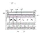
图2是本发明第一实施例的热电发电装置剖视图。Fig. 2 is a cross-sectional view of the thermoelectric power generation device according to the first embodiment of the present invention.
图3是本发明第一实施例的热电发电装置的吸热结构中碳纳米管絮化膜的扫描电镜照片。Fig. 3 is a scanning electron micrograph of a carbon nanotube flocculated film in the heat absorbing structure of the thermoelectric power generation device according to the first embodiment of the present invention.
图4是本发明第一实施例的热电发电装置的吸热结构中碳纳米管碾压膜的扫描电镜照片。4 is a scanning electron micrograph of a carbon nanotube rolled film in the heat absorbing structure of the thermoelectric power generation device according to the first embodiment of the present invention.
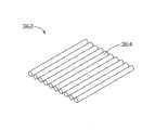
图5是本发明第一实施例的热电发电装置的吸热结构中碳纳米管拉膜的扫描电镜照片。5 is a scanning electron micrograph of a carbon nanotube drawn film in the heat absorbing structure of the thermoelectric power generation device according to the first embodiment of the present invention.
图6是图5中的碳纳米管拉膜中碳纳米管片断的结构示意图。FIG. 6 is a schematic structural view of carbon nanotube segments in the carbon nanotube drawn film in FIG. 5 .
图7是本发明第二实施例的热电发电装置剖视图。7 is a cross-sectional view of a thermoelectric power generation device according to a second embodiment of the present invention.
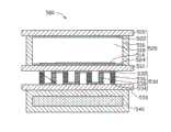
图8是本发明第三实施例的热电发电装置剖视图。Fig. 8 is a cross-sectional view of a thermoelectric power generation device according to a third embodiment of the present invention.
图9是本发明第四实施例的热电发电装置剖视图。9 is a cross-sectional view of a thermoelectric power generation device according to a fourth embodiment of the present invention.
具体实施方式Detailed ways
以下将结合附图及具体实施例详细说明本发明提供的热电发电装置。The thermoelectric power generation device provided by the present invention will be described in detail below with reference to the drawings and specific embodiments.
请参阅图2,本发明第一实施例提供一种热电发电装置300,该热电发电装置300包括:一集热器320、一热电转换装置330及一制冷装置340。所述集热器320可用于收集热量,并将所收集的热量传递给热电转换装置330,所述的制冷装置340与热电转换装置330相对设置。Please refer to FIG. 2 , the first embodiment of the present invention provides a thermoelectric
所述的集热器320包括一上基板310、一下基板312、一边框支架316、一吸热结构314、一第一选择性透过层322、一第二选择性透过层324、一承载体326及一支撑物(图未示)。所述上基板310和下基板312相对设置,所述边框支架316设置于所述上基板310和下基板312之间,所述上基板310、下基板312及边框支架316共同构成一空腔318,所述吸热结构314设置于空腔318内部,所述的承载体326用于承载所述的吸热结构314并与该吸热结构314接触设置,所述第一选择性透过层322设置于上基板310位于空腔318内的表面,所述第二选择性透过层324设置于下基板312位于空腔318内的表面,所述支撑物设置于空腔318内部并设置于下基板312与上基板310之间。The
所述上基板310为一透光基板,该上基板310采用透光材料制成,如玻璃、塑料、石英、透明陶瓷、树脂等。所述上基板310的厚度为100微米~5毫米,优选为3毫米。所述上基板310的形状不限,可以是三角形、六边形、四边形等,本实施例中该上基板310的形状为长方形的玻璃板。The
所述下基板312可采用玻璃或导热性较好的金属材料制成,该金属材料可选自锌、铝或不锈钢等。所述下基板312的厚度为100微米~5毫米,优选为3毫米。所述下基板312的形状不限,可以是三角形、六边形、四边形等,本实施例中该下基板312的形状为长方形的玻璃板。The
所述边框支架316可采用硬性材料制成,如玻璃、陶瓷等。所述边框支架316的高度为100微米~500微米,优选为150微米~250微米。The
所述空腔318内可为真空绝热环境、也可填充有导热效果较差的气体或填充有能够透光且保温的材料,所述导热效果较差的气体包括氮气等,所述透光且保温的材料可为透明的泡沫型保温材料,如耐热塑料等。该空腔318优选为真空绝热环境,以抑制空气的自然对流,从而减少所述集热器320中对流换热的损失,起到保温作用,从而大大提高所述集热器320的吸热效率。The
所述吸热结构314包括至少一由纯碳纳米管组成的碳纳米管结构或由其它基体与碳纳米管组成的碳纳米管复合结构。所述的基体材料为无机材料、金属材料或有机聚合物,优选为导热性好的材料,如氧化铝、银、铜或镍等。所述吸热结构314对太阳光的吸收率随吸热结构314厚度的增加而增加,因为,该吸热结构314的厚度越厚,其单位时间内吸收的热量越多,即所述吸热结构314的厚度越厚,对于太阳光的吸收效率越高。本实施例中,所述吸热结构314的厚度大于3微米。The
所述碳纳米管包括单壁碳纳米管、双壁碳纳米管或多壁碳纳米管中的一种或者多种。所述单壁碳纳米管的直径为0.5纳米~50纳米。所述双壁碳纳米管的直径为1.0纳米~50纳米。所述多壁碳纳米管的直径为1.5纳米~50纳米。The carbon nanotubes include one or more of single-wall carbon nanotubes, double-wall carbon nanotubes or multi-wall carbon nanotubes. The single-walled carbon nanotubes have a diameter of 0.5 nanometers to 50 nanometers. The diameter of the double-walled carbon nanotube is 1.0 nanometers to 50 nanometers. The diameter of the multi-walled carbon nanotubes is 1.5 nanometers to 50 nanometers.
所述碳纳米管结构包括至少一碳纳米管膜、至少一碳纳米管线状结构、碳纳米管膜和碳纳米管线状结构的组合或至少一碳纳米管阵列。所述碳纳米管膜中的碳纳米管可以有序排列或无序排列,无序指碳纳米管的排列方向不固定,即沿各方向排列的碳纳米管的数量基本相等,有序指至少多数碳纳米管的排列方向具有一定规律,如基本沿一个固定方向择优取向或基本沿几个固定方向择优取向。所述无序排列的碳纳米管可以通过范德华力相互缠绕、相互吸引且平行于碳纳米管结构的表面。所述有序排列的碳纳米管可以沿一个方向或多个方向择优取向排列。当碳纳米管结构仅包括一个碳纳米管线状结构时,该碳纳米管线状结构可以多次折叠或缠绕而成一层状碳纳米管结构。当碳纳米管结构包括多个碳纳米管线状结构时,多个碳纳米管线状结构可以相互平行设置,交叉设置或编织设置。当碳纳米管结构同时包括碳纳米管膜和碳纳米管线状结构时,所述碳纳米管线状结构设置于碳纳米管膜的至少一表面。The carbon nanotube structure includes at least one carbon nanotube film, at least one carbon nanotube linear structure, a combination of carbon nanotube film and carbon nanotube linear structure, or at least one carbon nanotube array. The carbon nanotubes in the carbon nanotube film can be arranged in an orderly or disorderly manner. Disorder means that the arrangement direction of the carbon nanotubes is not fixed, that is, the number of carbon nanotubes arranged in each direction is basically equal, and order means at least The arrangement direction of most carbon nanotubes has certain rules, such as preferential orientation basically along one fixed direction or preferential orientation basically along several fixed directions. The carbon nanotubes arranged in disorder can be intertwined and attracted to each other and parallel to the surface of the carbon nanotube structure through van der Waals force. The ordered carbon nanotubes can be preferentially aligned along one direction or multiple directions. When the carbon nanotube structure only includes one carbon nanotube wire structure, the carbon nanotube wire structure can be folded or intertwined multiple times to form a layered carbon nanotube structure. When the carbon nanotube structure includes a plurality of carbon nanotube linear structures, the plurality of carbon nanotube linear structures can be arranged parallel to each other, crossed or braided. When the carbon nanotube structure includes both a carbon nanotube film and a carbon nanotube linear structure, the carbon nanotube linear structure is arranged on at least one surface of the carbon nanotube film.
所述的碳纳米管膜包括碳纳米管絮化膜、碳纳米管碾压膜、碳纳米管拉膜。The carbon nanotube film includes a carbon nanotube flocculated film, a carbon nanotube rolled film, and a carbon nanotube drawn film.
请参见图3,所述碳纳米管絮化膜为各向同性,其包括多个无序排列且均匀分布的碳纳米管。碳纳米管长度较长,并通过范德华力相互吸引、相互缠绕。因此,碳纳米管絮化膜具有很好的柔韧性,可以弯曲折叠成任意形状而不破裂,且具有较好的自支撑性能,可无需基底支撑而自支撑存在。所述碳纳米管絮化膜中碳纳米管的长度大于10微米。所述碳纳米管絮化膜的厚度为0.5纳米-1毫米。所述碳纳米管絮化膜为将一碳纳米管原料经絮化处理得到。所述碳纳米管絮化膜及其制备方法请参见本申请人于2007年4月13日申请的第200710074027.5号大陆专利申请(申请人:清华大学;鸿富锦精密工业(深圳)有限公司)。为节省篇幅,仅引用于此,但上述申请所有技术揭露也应视为本发明申请技术揭露的一部分。Please refer to FIG. 3 , the carbon nanotube flocculation film is isotropic, which includes a plurality of carbon nanotubes arranged in disorder and evenly distributed. Carbon nanotubes are long and attract and entangle with each other through van der Waals force. Therefore, the carbon nanotube flocculation film has good flexibility, can be bent and folded into any shape without breaking, and has good self-supporting performance, and can exist on its own without substrate support. The length of the carbon nanotubes in the carbon nanotube flocculated film is greater than 10 microns. The thickness of the carbon nanotube flocculation film is 0.5 nm-1 mm. The carbon nanotube flocculated film is obtained by flocculating a carbon nanotube raw material. For the carbon nanotube flocculated film and its preparation method, please refer to the mainland patent application No. 200710074027.5 filed by the applicant on April 13, 2007 (Applicant: Tsinghua University; Hongfujin Precision Industry (Shenzhen) Co., Ltd.) . To save space, it is only cited here, but all the technical disclosures of the above applications should also be regarded as a part of the technical disclosures of the present application.
所述碳纳米管碾压膜为采用一压头或压板沿同一方向或不同方向碾压一碳纳米管阵列得到。所述碳纳米管碾压膜包括均匀分布的碳纳米管,碳纳米管各向同性、沿同一方向或不同方向择优取向排列。该碳纳米管碾压膜中的碳纳米管与形成碳纳米管阵列的基体的表面成一夹角α,其中,α大于等于0度且小于等于15度(0≤α≤15°)。依据碾压的方式不同,该碳纳米管碾压膜中的碳纳米管具有不同的排列形式。具体地,碳纳米管可以各向同性排列,当沿不同方向碾压时,碳纳米管沿不同方向择优取向排列,请参见图4,碳纳米管在碳纳米管碾压膜中可沿一固定方向择优取向排列,也可沿不同方向择优取向排列。所述碳纳米管碾压膜中的碳纳米管部分交叠。所述碳纳米管碾压膜中碳纳米管之间通过范德华力相互吸引,紧密结合,使得该碳纳米管碾压膜具有很好的柔韧性,可以弯曲折叠成任意形状而不破裂。且由于碳纳米管碾压膜中的碳纳米管之间通过范德华力相互吸引,紧密结合,使碳纳米管碾压膜为一自支撑的结构,可无需基底支撑而自支撑存在。所述碳纳米管碾压膜的厚度为0.5纳米-1毫米。所述碳纳米管碾压膜及其制备方法请参见本申请人于2007年6月1日申请的第200710074699.6号大陆专利申请(申请人:清华大学;鸿富锦精密工业(深圳)有限公司)。为节省篇幅,仅引用于此,但上述申请所有技术揭露也应视为本发明申请技术揭露的一部分。The carbon nanotube rolling film is obtained by rolling a carbon nanotube array in the same direction or in different directions by using a pressing head or a pressing plate. The carbon nanotube rolling film includes uniformly distributed carbon nanotubes, and the carbon nanotubes are isotropic and arranged in preferred orientations along the same direction or in different directions. The carbon nanotubes in the carbon nanotube rolled film form an angle α with the surface of the matrix forming the carbon nanotube array, wherein α is greater than or equal to 0 degrees and less than or equal to 15 degrees (0≤α≤15°). According to different rolling methods, the carbon nanotubes in the carbon nanotube rolling film have different arrangement forms. Specifically, the carbon nanotubes can be arranged isotropically. When rolled in different directions, the carbon nanotubes are preferentially aligned in different directions. Please refer to Figure 4. The carbon nanotubes can be fixed along a fixed direction in the carbon nanotube rolled film The preferred orientation is arranged in the direction, and the preferred orientation can also be arranged in different directions. The carbon nanotubes in the carbon nanotube rolled film are partially overlapped. The carbon nanotubes in the carbon nanotube rolling film are attracted to each other by van der Waals force and are closely combined, so that the carbon nanotube rolling film has good flexibility and can be bent and folded into any shape without breaking. Moreover, because the carbon nanotubes in the carbon nanotube rolling film are attracted to each other by van der Waals force and are closely combined, the carbon nanotube rolling film is a self-supporting structure, which can exist without the support of the substrate. The carbon nanotube rolling film has a thickness of 0.5 nanometers to 1 millimeter. For the carbon nanotube rolling film and its preparation method, please refer to the mainland patent application No. 200710074699.6 filed by the applicant on June 1, 2007 (Applicant: Tsinghua University; Hongfujin Precision Industry (Shenzhen) Co., Ltd.) . To save space, it is only cited here, but all the technical disclosures of the above applications should also be regarded as a part of the technical disclosures of the present application.
请参见图5,所述碳纳米管拉膜为从一超顺排碳纳米管阵列中拉取获得,该碳纳米管拉膜包括多个首尾相连且沿拉伸方向择优取向排列的碳纳米管。所述碳纳米管均匀分布,且平行于碳纳米管膜表面。所述碳纳米管膜中的碳纳米管之间通过范德华力连接。一方面,首尾相连的碳纳米管之间通过范德华力连接,另一方面,平行的碳纳米管之间部分亦通过范德华力结合。请参阅图6,所述碳纳米管拉膜进一步包括多个首尾相连的碳纳米管片段362,每个碳纳米管片段362由多个相互平行的碳纳米管364构成,碳纳米管片段362两端通过范德华力相互连接。该碳纳米管片段362具有任意的长度、厚度、均匀性及形状。所述碳纳米管拉膜的厚度为0.5纳米-100微米。所述碳纳米管拉膜结构及其制备方法请参见本申请人于2007年2月9日申请的,于2008年8月13公开的第CN101239712A号大陆公开专利申请(申请人:清华大学;鸿富锦精密工业(深圳)有限公司)。为节省篇幅,仅引用于此,但上述申请所有技术揭露也应视为本发明申请技术揭露的一部分。Please refer to Figure 5, the drawn carbon nanotube film is drawn from a super-aligned carbon nanotube array, and the drawn carbon nanotube film includes a plurality of carbon nanotubes connected end to end and arranged in a preferred orientation along the stretching direction . The carbon nanotubes are uniformly distributed and parallel to the surface of the carbon nanotube film. The carbon nanotubes in the carbon nanotube film are connected by van der Waals force. On the one hand, the end-to-end carbon nanotubes are connected by van der Waals force, and on the other hand, the parts between parallel carbon nanotubes are also bonded by van der Waals force. Please refer to FIG. 6 , the carbon nanotube stretched film further includes a plurality of end-to-end
可以理解,所述碳纳米管结构可以进一步包括至少两个层叠设置的碳纳米管膜。由于碳纳米管结构中的碳纳米管膜可层叠设置,故,上述碳纳米管结构的厚度不限,可根据实际需要制成具有任意厚度的碳纳米管结构。当碳纳米管结构包括多个层叠设置的碳纳米管拉膜时,相邻的碳纳米管拉膜中的碳纳米管的排列方向形成一夹角β,0°≤β≤90°。It can be understood that the carbon nanotube structure may further include at least two carbon nanotube films stacked. Since the carbon nanotube films in the carbon nanotube structure can be stacked, the thickness of the above-mentioned carbon nanotube structure is not limited, and a carbon nanotube structure with any thickness can be produced according to actual needs. When the carbon nanotube structure includes a plurality of laminated carbon nanotube drawn films, the arrangement directions of the carbon nanotubes in adjacent carbon nanotube drawn films form an included angle β, 0°≤β≤90°.
所述碳纳米管线状结构包括至少一非扭转的碳纳米管线、至少一扭转的碳纳米管线或其组合。所述碳纳米管线状结构包括多根非扭转的碳纳米管线或扭转的碳纳米管线时,该非扭转的碳纳米管线或扭转的碳纳米管线可以相互平行呈一束状结构,或相互扭转呈一绞线结构。The carbon nanotube wire structure includes at least one non-twisted carbon nanotube wire, at least one twisted carbon nanotube wire or a combination thereof. When the carbon nanotube wire structure includes a plurality of non-twisted carbon nanotube wires or twisted carbon nanotube wires, the non-twisted carbon nanotube wires or twisted carbon nanotube wires can be parallel to each other to form a bundle structure, or twisted to form a bundle structure. A stranded wire structure.
非扭转的碳纳米管线为将碳纳米管拉膜通过有机溶剂处理得到。具体地,将有机溶剂浸润所述碳纳米管拉膜的整个表面,在挥发性有机溶剂挥发时产生的表面张力的作用下,碳纳米管拉膜中的相互平行的多个碳纳米管通过范德华力紧密结合,从而使碳纳米管拉膜收缩为一非扭转的碳纳米管线。该有机溶剂为挥发性有机溶剂,如乙醇、甲醇、丙酮、二氯乙烷或氯仿,本实施例中采用乙醇。通过有机溶剂处理的非扭转碳纳米管线与未经有机溶剂处理的碳纳米管膜相比,比表面积减小,粘性降低。The non-twisted carbon nanotube wire is obtained by treating the carbon nanotube stretched film with an organic solvent. Specifically, the organic solvent is soaked into the entire surface of the carbon nanotube film, and under the action of the surface tension generated when the volatile organic solvent volatilizes, a plurality of carbon nanotubes in the carbon nanotube film that are parallel to each other pass through the van der Waals film. The force is closely combined, so that the carbon nanotube film shrinks into a non-twisted carbon nanotube wire. The organic solvent is a volatile organic solvent, such as ethanol, methanol, acetone, dichloroethane or chloroform, and ethanol is used in this embodiment. Compared with the carbon nanotube film without organic solvent treatment, the non-twisted carbon nanotube wire treated by organic solvent has a smaller specific surface area and lower viscosity.
所述扭转的碳纳米管线为采用一机械力将所述碳纳米管拉膜两端沿相反方向扭转获得。进一步地,可采用一挥发性有机溶剂处理该扭转的碳纳米管线。在挥发性有机溶剂挥发时产生的表面张力的作用下,处理后的扭转的碳纳米管线中相邻的碳纳米管通过范德华力紧密结合,使扭转的碳纳米管线的比表面积减小,密度及强度增大。The twisted carbon nanotube wire is obtained by using a mechanical force to twist the two ends of the carbon nanotube film in opposite directions. Further, the twisted carbon nanotubes can be treated with a volatile organic solvent. Under the action of the surface tension generated when the volatile organic solvent volatilizes, the adjacent carbon nanotubes in the treated twisted carbon nanotubes are closely combined by van der Waals force, so that the specific surface area of the twisted carbon nanotubes is reduced, and the density and Increased strength.
所述碳纳米管线状结构及其制备方法请参见本申请人于2002年9月16日申请的,于2008年8月20日公告的第CN100411979C号中国大陆公告专利(申请人:清华大学;鸿富锦精密工业(深圳)有限公司),以及本申请人于2005年12月16日申请的,于2007年6月20日公开的第CN1982209A号中国大陆公开专利申请(申请人:清华大学;鸿富锦精密工业(深圳)有限公司)。为节省篇幅,仅引用于此,但上述申请所有技术揭露也应视为本发明申请技术揭露的一部分。For the linear structure of carbon nanotubes and the preparation method thereof, please refer to the CN100411979C Mainland China Announcement Patent (Applicant: Tsinghua University; Fujin Precision Industry (Shenzhen) Co., Ltd.), and the Chinese mainland patent application No. CN1982209A, which was applied by the applicant on December 16, 2005 and published on June 20, 2007 (applicant: Tsinghua University; Hong Fujin Precision Industry (Shenzhen) Co., Ltd.). To save space, it is only cited here, but all the technical disclosures of the above applications should also be regarded as a part of the technical disclosures of the present application.
所述碳纳米管阵列为通过化学气相沉积法或其它方法直接生长获得。所述碳纳米管阵列包括多个彼此基本平行的碳纳米管。The carbon nanotube array is directly grown by chemical vapor deposition or other methods. The carbon nanotube array includes a plurality of carbon nanotubes substantially parallel to each other.
所述的碳纳米管复合结构中,所述碳纳米管在碳纳米管复合结构中的含量为80%以上。其中,由上述碳纳米管结构和其它有机聚合物基体组成的碳纳米管复合结构的制备方法为:将上述碳纳米管结构浸入一掺杂有固化剂等添加物的有机聚合物溶液中,并将该有机聚合物溶液进行固化处理。由上述碳纳米管结构和其它无机材料或金属材料基体组成的碳纳米管复合结构的制备方法为:将上述碳纳米管结构浸入一含有金属粉或无机粉体的有机溶剂中,之后挥发所述的有机溶剂。另外,该碳纳米管复合结构的制备方法还可为:首先,将多个碳纳米管混入一定的溶剂(如1,2-二氯乙烷)中超声分散处理或采取其它方式使碳纳米管分散均匀;然后,再将其与一定的有机载体混合(如松油醇与纤维素的混合物)并固化,从而制得碳纳米管复合结构。In the carbon nanotube composite structure, the content of the carbon nanotube in the carbon nanotube composite structure is more than 80%. Wherein, the preparation method of the carbon nanotube composite structure composed of the above-mentioned carbon nanotube structure and other organic polymer matrix is: immersing the above-mentioned carbon nanotube structure in an organic polymer solution doped with additives such as curing agent, and This organic polymer solution is subjected to curing treatment. The preparation method of the carbon nanotube composite structure composed of the above-mentioned carbon nanotube structure and other inorganic materials or metal material matrix is: immerse the above-mentioned carbon nanotube structure in an organic solvent containing metal powder or inorganic powder, and then volatilize the of organic solvents. In addition, the preparation method of the carbon nanotube composite structure can also be as follows: first, a plurality of carbon nanotubes are mixed into a certain solvent (such as 1,2-dichloroethane) for ultrasonic dispersion treatment or other methods are used to make the carbon nanotubes Disperse evenly; then, mix it with a certain organic carrier (such as a mixture of terpineol and cellulose) and solidify, so as to obtain a carbon nanotube composite structure.
本实施例中,所述吸热结构314包括一碳纳米管结构,所述碳纳米管结构包括层叠设置的多层碳纳米管拉膜,所述吸热结构314的吸热效率随厚度的增加而增加。当吸热结构314的厚度为10微米时,该吸热结构314的吸热效率可以达到96%。In this embodiment, the heat-absorbing
由于本实施例中,所述碳纳米管拉膜是从超顺排碳纳米管阵列拉取得到,其长度和宽度可以较准确地控制。且该碳纳米管拉膜具有韧性,可以弯折成任意形状,方便制成各种形状的集热器,适于各种应用。Since in this embodiment, the drawn carbon nanotube film is drawn from a super-aligned carbon nanotube array, its length and width can be controlled more accurately. Moreover, the carbon nanotube stretched film has toughness, can be bent into any shape, and can be conveniently made into heat collectors of various shapes, and is suitable for various applications.
另外,碳纳米管对电磁波的吸收接近绝对黑体,对各种波长的光具有均一的吸收特性,故碳纳米管对于太阳光有较好的吸收特性,照射到碳纳米管膜上的93%~98%的太阳光都可被碳纳米管膜所吸收。In addition, the absorption of electromagnetic waves by carbon nanotubes is close to that of an absolute black body, and has uniform absorption characteristics for light of various wavelengths, so carbon nanotubes have better absorption characteristics for sunlight, and 93%~ 98% of sunlight can be absorbed by carbon nanotube film.
所述第一选择性透过层322和第二选择性透过层324为一红外选择性透过层。该第一选择性透过层322和第二选择性透过层324对于紫外光、可见光和近红外线的透过率较高,且可反射远红外线。当吸热结构314吸收太阳光之后,会继续向外辐射远红外线,所辐射的远红外线可通过第一选择性透过层322和第二选择性透过层324反射,反射的远红外线可再次被吸热结构314吸收,从而可以减少所述集热器320对太阳能能量的辐射损失,增大该集热器320对太阳能的能量转化效率。所述第一选择性透过层322和第二选择性透过层324的厚度为10纳米~1微米。The first
所述第一选择性透过层322和第二选择性透过层324可以为氧化铟锡薄膜、氧化锌铝膜、多层光学膜、碳纳米管结构或碳纳米管复合结构。该碳纳米管结构或碳纳米管复合结构中的碳纳米管有序排列或无序排列。本实施例中该第一选择性透过层322和第二选择性透过层324的材料为氧化铟锡薄膜。The first
所述承载体326设置于吸热结构314和热电转换装置330之间,该承载体326与吸热结构314接触设置,且该承载体326用于承载所述的吸热结构314。该承载体326的材料为具有较高导热系数的材料,如玻璃、铜、铝等。The
所述支撑物的高度等于所述边框支架316的高度。该支撑物是由吸热性较弱的材料制成,如玻璃或陶瓷,其形状不限,可以为玻璃珠或者玻璃柱等。当上下基板面积较大时,该多个支撑物可使上下基板间隔设置,以抵抗来自大气的压力。The height of the support is equal to the height of the
所述热电转换装置330设置于集热器320的空腔318内,并设置于所述第二选择性透过层324和承载体326之间,用于支撑所述承载体326和吸热结构314。该热电转换装置330包括:多个第一电极332,多个第二电极334,多个P型热电结构336及多个N型热电结构338。所述多个P型热电结构336和多个N型热电结构338交替间隔排列并通过多个第一电极332和多个第二电极334交替串联。具体为当该热电转换装置330工作时,电流交替通过P型热电结构336和N型热电结构338。所述第一电极332与上述集热器320的吸热结构314相对并热耦合且通过承载体326间隔设置,所述第二电极334与上述集热器320的第二选择性透过层324接触设置。The
所述制冷装置340设置于上述集热器320的下基板312位于空腔318外的表面,该制冷装置340可进一步降低上述热电转换装置330的低温端的温度,使高温端和低温端的温差增大,从而进一步提高热电发电装置300的热电转换效率。该制冷装置340的冷却方式可以为水冷、风冷或散热片自然冷却等。本实施例为一水冷装置。The refrigerating
本实施例提供的热电发电装置300,由于吸热结构314为碳纳米管结构,其在可见波段的吸收率可达到98%以上,另外,由于该热电发电装置300的吸热结构314及热电转换装置330均设置在一真空腔318中,减少了气体分子的运动传热和传导散热,从而升高了热电转换装置330的高温端温度,经测量可达到100℃左右,从而使得热能向电能的转换效率Φmax提高。In the thermoelectric
本实施例的热电发电装置300可仅包括集热器320及热电转换装置330,且所述集热器320可仅包括所述的吸热结构314,将该吸热结构314直接设置于所述热电转换装置330的第一电极332便可实现本发明之目的。The thermoelectric
请参阅图7,本发明第二实施例提供一种热电发电装置400,该热电发电装置400包括一集热器420、一热电转换装置430及一制冷装置440。所述集热器320可用于收集太阳能,并将所收集的太阳能传递给热电转换装置330,所述的制冷装置340与热电转换装置330相对设置。Please refer to FIG. 7 , the second embodiment of the present invention provides a thermoelectric
所述的集热器420包括一上基板410、一下基板412、一边框支架416、多个吸热结构414、一第一选择性透过层422、一第二选择性透过层424及一承载体426。所述上基板410和所述下基板412相对设置。所述边框支架416设置于所述上基板410和下基板412之间。所述上基板410、下基板412及边框支架416共同构成一空腔418。所述吸热结构414设置于空腔418内部。所述的承载体426用于承载所述的吸热结构414并与该吸热结构414接触设置。所述第一选择性透过层422设置于上基板410位于空腔418内的表面,所述第二选择性透过层424设置于下基板412位于空腔418内的表面。The
所述热电转换装置430设置于集热器420的空腔418内,并设置于所述第二选择性透过层424和承载体426之间,用于支撑所述承载体426和吸热结构414。所述热电转换装置430包括至少一个第一电极432、至少一个第二电极434、P型热电结构436及N型热电结构438,所述第一电极432与吸热结构414相对并热耦合且通过所述承载体426间隔设置,所述第二电极434与集热器420的第二选择性透过层424接触设置,所述P型热电结构436和N型热电结构438交替间隔排列并通过第一电极432和第二电极434交替串联。The
本实施例提供的热电发电装置400与上述第一实施例提供的热电发电装置300的区别在于,本实施的热电发电装置400包括多个分离吸热结构414,其中每个吸热结构414对应设置于热电转换装置430的一个第一电极432的表面。The difference between the thermoelectric
请参阅图8,本发明第三实施例提供一种热电发电装置500,该热电发电装置500包括一集热器520、一热电转换装置530、一支撑元件550及一制冷装置540。所述集热器520与所述热电转换装置530相对设置,所述集热器520可用于收集太阳能并将所收集的太阳能传递给热电转换装置530。所述的支撑元件550设置于所述热电转换装置530与所述的制冷装置540之间,并用于支撑所述的热电转换装置530。所述的制冷装置540设置于所述支撑元件550远离热电转换装置530的表面。Please refer to FIG. 8 , the third embodiment of the present invention provides a thermoelectric
所述的集热器520包括一上基板510、一下基板512、一边框支架516一吸热结构514、一第一选择性透过层522及一第二选择性透过层524。所述上基板510和所述下基板512相对设置。所述边框支架516设置于所述上基板510和下基板512之间。所述上基板510、下基板512及边框支架516共同构成一空腔518。所述吸热结构514设置于空腔518内且与第二选择性透过层524接触设置。所述第一选择性透过层522设置于上基板510位于空腔518内的表面,所述第二选择性透过层524设置于下基板512与所述吸热结构514之间。The
所述热电转换装置530设置于下基板512位于空腔518外的表面,所述热电转换装置530包括:至少一个第一电极532,该第一电极532与集热器520的下基板512位于空腔518外的表面接触;至少一个第二电极534,该第二电极534与第一电极532相对设置;P型热电结构536及N型热电结构538,该P型热电结构536和N型热电结构538交替间隔排列并通过第一电极532和第二电极534交替串联。The
所述支撑元件550用于支撑热电转换装置530,且可进一步固定该热电转换装置530的P型热电结构536及N型热电结构538,其材料为玻璃、陶瓷或导热性较好的材料,如铜、铝等。The supporting
所述制冷装置540可进一步降低上述热电转换装置530的低温端的温度,使高温端和低温端的温差增大,从而进一步提高热电发电装置500的热电转换效率。该制冷装置540的冷却方式可以为水冷、风冷或散热片自然冷却等。本实施例中,该制冷装置540为水冷装置。另外,该制冷装置540可直接代替支撑元件542,直接设置于上述热电转换装置530的第二电极534。The refrigerating
本实施例与第一实施例基本相同,其区别在于,本实施例的热电转换装置530设置在所述集热器520的外部,所述吸热结构514直接与所述第二选择性透过层524接触设置。This embodiment is basically the same as the first embodiment, the difference is that the
请参阅图9,本发明第四实施例提供一种热电发电装置600,该热电发电装置600包括一集热器620、一热电转换装置630、一支撑元件650及一制冷装置640。所述集热器620与所述热电转换装置630相对设置。所述集热器620与所述热电转换装置630相对设置。所述集热器620可用于收集太阳能,并将所收集的太阳能传递给热电转换装置630。所述的支撑元件650设置于所述热电转换装置630与所述的制冷装置640之间,并用于支撑所述的热电转换装置630。所述的制冷装置640设置于所述支撑元件650。Please refer to FIG. 9 , the fourth embodiment of the present invention provides a thermoelectric
所述的集热器620包括一上基板610、一下基板612、一边框支架616、多个吸热结构614、一第一选择性透过层622和一第二选择性透过层624。所述上基板610和所述下基板612相对设置,所述边框支架616设置于所述上基板610和下基板612之间,所述上基板610、下基板612及边框支架616共同构成一空腔618,所述吸热结构614设置于所述空腔618内并与所述第二选择性透过层624接触设置,所述第一选择性透过层622设置于上基板610位于空腔618内的表面,所述第二选择性透过层624设置于下基板612与吸热结构614之间。The
所述热电转换装置630设置于下基板612位于空腔618外的表面。该热电转换装置630包括:至少一个第一电极632,该第一电极632与集热器620的下基板612的外表面接触;至少一个第二电极634,该第二电极634与第一电极632相对设置;P型热电结构636及N型热电结构638,该P型热电结构636和N型热电结构638交替间隔排列并通过第一电极632和第二电极634交替串联。The
本实施例与上述第三实施例的热电发电装置500的区别在于,本实施例的热电发电装置500包括多个分离的吸热结构614,该多个吸热结构614在一个平面内间隔设置,并且每个吸热结构614正对热电转换装置630的一个第一电极632设置。这种设置方式既可以保证每个第一电极均与吸热结构保持良好的热接触,又可以节省碳纳米管的消耗,节约成本。The difference between this embodiment and the thermoelectric
所述热电发电装置采用碳纳米管结构作吸热结构,利用碳纳米管结构良好的吸热特性,可提高集热器的能量吸收效率,从而进一步提高了热电转换装置高温端的温度,使得该热电发电装置的热电转换效率较高。The thermoelectric power generation device adopts the carbon nanotube structure as the heat-absorbing structure, and the good heat-absorbing characteristics of the carbon nanotube structure can improve the energy absorption efficiency of the heat collector, thereby further increasing the temperature at the high-temperature end of the thermoelectric conversion device, so that the thermoelectric The thermoelectric conversion efficiency of the power generation device is relatively high.
另外,本领域技术人员还可在本发明精神内做其他变化,当然,这些依据本发明精神所做的变化,都应包含在本发明所要求保护的范围之内。In addition, those skilled in the art can also make other changes within the spirit of the present invention. Of course, these changes made according to the spirit of the present invention should be included within the scope of protection claimed by the present invention.
Claims (21)
Priority Applications (3)
| Application Number | Priority Date | Filing Date | Title |
|---|---|---|---|
| CN2009101054900ACN101814867B (en) | 2009-02-20 | 2009-02-20 | Thermoelectric generator |
| US12/583,425US9263660B2 (en) | 2009-02-20 | 2009-08-20 | Generator |
| JP2010027844AJP5038447B2 (en) | 2009-02-20 | 2010-02-10 | Thermoelectric generator |
Applications Claiming Priority (1)
| Application Number | Priority Date | Filing Date | Title |
|---|---|---|---|
| CN2009101054900ACN101814867B (en) | 2009-02-20 | 2009-02-20 | Thermoelectric generator |
Publications (2)
| Publication Number | Publication Date |
|---|---|
| CN101814867A CN101814867A (en) | 2010-08-25 |
| CN101814867Btrue CN101814867B (en) | 2013-03-20 |
Family
ID=42622011
Family Applications (1)
| Application Number | Title | Priority Date | Filing Date |
|---|---|---|---|
| CN2009101054900AActiveCN101814867B (en) | 2009-02-20 | 2009-02-20 | Thermoelectric generator |
Country Status (3)
| Country | Link |
|---|---|
| US (1) | US9263660B2 (en) |
| JP (1) | JP5038447B2 (en) |
| CN (1) | CN101814867B (en) |
Families Citing this family (24)
| Publication number | Priority date | Publication date | Assignee | Title |
|---|---|---|---|---|
| CN101880035A (en) | 2010-06-29 | 2010-11-10 | 清华大学 | carbon nanotube structure |
| JP5119407B2 (en)* | 2011-03-28 | 2013-01-16 | 国立大学法人信州大学 | Light absorbing film, method for producing the same, and solar collector using the same |
| CN102510244B (en)* | 2011-12-02 | 2014-04-16 | 浙江大学 | Annular array thermoelectric generator with functional gradient thermoelectric arms |
| JP6370532B2 (en)* | 2012-05-11 | 2018-08-08 | 公立大学法人大阪府立大学 | PHOTO-HEAT CONVERSION ELEMENT AND MANUFACTURING METHOD THEREOF, PHOTO-HEAT POWER GENERATION DEVICE, AND DETECTING METHOD |
| US9960288B2 (en) | 2012-08-09 | 2018-05-01 | The United State of America as represented by the Administrator of NASA | Solar radiation control and energy harvesting film |
| CN103206275A (en)* | 2012-09-19 | 2013-07-17 | 广西南宁市派宇能源科技开发有限公司 | Light, heat and electricity converting device |
| KR102176589B1 (en)* | 2012-11-16 | 2020-11-10 | 삼성전자주식회사 | Thermoelectric material, thermoelectric device and apparatus comprising same, and preparation method thereof |
| TW201422903A (en)* | 2012-12-10 | 2014-06-16 | Ind Tech Res Inst | Thermoelectric generatorand thermoelectric generating system |
| CH707391A2 (en)* | 2012-12-28 | 2014-06-30 | Greenteg Ag | Thermoelectric converter. |
| CN104868045B (en) | 2014-02-21 | 2017-10-24 | 清华大学 | Electrooptical device and its application |
| KR101636908B1 (en)* | 2014-05-30 | 2016-07-06 | 삼성전자주식회사 | Stretchable thermoelectric material and thermoelectric device including the same |
| US10720560B2 (en)* | 2014-09-11 | 2020-07-21 | Northwestern University | System and method for nanowire-array transverse thermoelectrics |
| CN104467540A (en)* | 2014-12-02 | 2015-03-25 | 天津大学 | Thermal energy collection and storage device applied to miniature thermoelectric battery |
| CN106531875A (en)* | 2016-10-19 | 2017-03-22 | 天津大学 | Light absorbing material layer for thermal energy collection of micro thermoelectric battery and manufacture method of light absorbing material layer |
| CN107356341A (en)* | 2017-03-10 | 2017-11-17 | 杭州立昂微电子股份有限公司 | Semiconductor thermoelectric module infrared detector and manufacture method |
| CN110031116A (en)* | 2018-01-11 | 2019-07-19 | 清华大学 | Cavate blackbody radiation source |
| US11716905B2 (en)* | 2018-06-22 | 2023-08-01 | Board Of Regents, The University Of Texas System | Liquid-based thermoelectric device |
| CN110885059B (en)* | 2019-04-23 | 2023-05-09 | 厦门大学 | A method for generating electricity from a carbon nanotube array |
| CN110131430A (en)* | 2019-05-14 | 2019-08-16 | 张思汉 | Thermal type automatic temperature-control water mixing valve |
| CN111446886B (en)* | 2020-03-23 | 2021-10-29 | 中国矿业大学 | A thermoelectric power generation device that can effectively increase the temperature of the end difference |
| CN113376461A (en)* | 2021-06-07 | 2021-09-10 | 中国南方电网有限责任公司超高压输电公司大理局 | Online detection device and method for faults in transformer shell |
| CN113391174B (en)* | 2021-06-07 | 2024-10-01 | 中国南方电网有限责任公司超高压输电公司大理局 | Positioning device and method for faults in transformer shell |
| CN113315416A (en)* | 2021-06-28 | 2021-08-27 | 上海交通大学 | All-weather continuous power generation device capable of being assembled in module mode |
| CN118890951B (en)* | 2024-09-20 | 2025-02-14 | 深圳大学 | Thermoelectric conversion device and building structure monitoring system |
Citations (2)
| Publication number | Priority date | Publication date | Assignee | Title |
|---|---|---|---|---|
| CN101001515A (en)* | 2006-01-10 | 2007-07-18 | 鸿富锦精密工业(深圳)有限公司 | Plate radiating pipe and manufacturing method thereof |
| CN101239712A (en)* | 2007-02-09 | 2008-08-13 | 清华大学 | Carbon nanotube film structure and preparation method thereof |
Family Cites Families (50)
| Publication number | Priority date | Publication date | Assignee | Title |
|---|---|---|---|---|
| US2984696A (en)* | 1959-03-09 | 1961-05-16 | American Mach & Foundry | Solar thermoelectric generators |
| US4822120A (en) | 1974-08-16 | 1989-04-18 | Massachusetts Institute Of Technology | Transparent heat-mirror |
| DE2612171A1 (en) | 1976-03-23 | 1977-09-29 | Philips Patentverwaltung | SOLAR COLLECTOR WITH EVACUATED ABSORBER COVER TUBE |
| US4106952A (en)* | 1977-09-09 | 1978-08-15 | Kravitz Jerome H | Solar panel unit |
| US4166880A (en)* | 1978-01-18 | 1979-09-04 | Solamat Incorporated | Solar energy device |
| JPS5792654A (en) | 1980-11-29 | 1982-06-09 | Inoue Japax Res Inc | Pipe that utilizes solar heat |
| JPS5852932A (en) | 1981-09-21 | 1983-03-29 | Sumitomo Metal Ind Ltd | solar heat collector |
| JPS6259342A (en) | 1985-09-06 | 1987-03-16 | Sumitomo Metal Ind Ltd | solar heat collecting panel board |
| JPH0579708A (en) | 1991-09-18 | 1993-03-30 | Kanai Hiroyuki | Solar heat collector |
| US5517339A (en)* | 1994-06-17 | 1996-05-14 | Northeast Photosciences | Method of manufacturing high efficiency, broad bandwidth, volume holographic elements and solar concentrators for use therewith |
| DE19704323C1 (en) | 1997-02-05 | 1998-07-02 | Saskia Solar Und Energietechni | Vacuum-containing thermal insulator |
| US6348650B1 (en)* | 1999-03-24 | 2002-02-19 | Ishizuka Electronics Corporation | Thermopile infrared sensor and process for producing the same |
| FR2793889B1 (en)* | 1999-05-20 | 2002-06-28 | Saint Gobain Vitrage | TRANSPARENT SUBSTRATE WITH ANTI-REFLECTIVE COATING |
| US6282907B1 (en)* | 1999-12-09 | 2001-09-04 | International Business Machines Corporation | Thermoelectric cooling apparatus and method for maximizing energy transport |
| JP2001226108A (en) | 2000-02-14 | 2001-08-21 | Denso Corp | Method for manufacturing carbon-based gas storage material |
| CN2457521Y (en) | 2000-12-21 | 2001-10-31 | 周堃 | Vacuum plate type solar energy collector |
| JP3579689B2 (en) | 2001-11-12 | 2004-10-20 | 独立行政法人 科学技術振興機構 | Manufacturing method of functional nanomaterial using endothermic reaction |
| US6965513B2 (en)* | 2001-12-20 | 2005-11-15 | Intel Corporation | Carbon nanotube thermal interface structures |
| CN1474113A (en) | 2002-08-06 | 2004-02-11 | 夏庆华 | Plate type plastic solar energy air conditioner |
| JP3524542B2 (en) | 2002-08-26 | 2004-05-10 | キヤノン株式会社 | Manufacturing method of carbon nanotube |
| CN100411979C (en) | 2002-09-16 | 2008-08-20 | 清华大学 | A carbon nanotube rope and its manufacturing method |
| JP2004211718A (en) | 2002-12-26 | 2004-07-29 | Nissan Motor Co Ltd | Hydrogen storage material, hydrogen storage device, and method for producing hydrogen storage body |
| US7481267B2 (en)* | 2003-06-26 | 2009-01-27 | The Regents Of The University Of California | Anisotropic thermal and electrical applications of composites of ceramics and carbon nanotubes |
| CN2641536Y (en) | 2003-09-09 | 2004-09-15 | 林子超 | Vacuum plate type solar energy heat collector |
| JP4380282B2 (en) | 2003-09-26 | 2009-12-09 | 富士ゼロックス株式会社 | Method for producing carbon nanotube composite structure |
| US7354877B2 (en) | 2003-10-29 | 2008-04-08 | Lockheed Martin Corporation | Carbon nanotube fabrics |
| TWI253467B (en) | 2003-12-23 | 2006-04-21 | Hon Hai Prec Ind Co Ltd | Thermal interface material and method for making same |
| JP4288188B2 (en) | 2004-01-19 | 2009-07-01 | 新日本製鐵株式会社 | Surface-treated metal material with excellent heat absorption and dissipation characteristics |
| JP2006001820A (en) | 2004-06-21 | 2006-01-05 | Dainatsukusu:Kk | Carbon-containing titanium oxynitride selective absorption membrane |
| US20060048808A1 (en) | 2004-09-09 | 2006-03-09 | Ruckman Jack H | Solar, catalytic, hydrogen generation apparatus and method |
| JP2006114826A (en) | 2004-10-18 | 2006-04-27 | Yamaha Corp | Thermally conductive substrate, thermoelectric module, and method for producing thermally conductive substrate |
| CN105696139B (en) | 2004-11-09 | 2019-04-16 | 得克萨斯大学体系董事会 | The manufacture and application of nano-fibre yams, band and plate |
| JP2006229168A (en) | 2005-02-21 | 2006-08-31 | Seiko Epson Corp | Heating method and heating apparatus |
| JP2006265079A (en) | 2005-03-25 | 2006-10-05 | Kyoto Institute Of Technology | Plasma chemical vapor deposition apparatus and carbon nanotube production method |
| TWI296610B (en) | 2005-05-12 | 2008-05-11 | Nat Univ Tsing Hua | Carbon nanotube fluffy ball and method of producing the same |
| US8545790B2 (en)* | 2005-06-04 | 2013-10-01 | Gregory Konesky | Cross-linked carbon nanotubes |
| CN100583349C (en) | 2005-07-15 | 2010-01-20 | 清华大学 | Field-transmitting cathode, its production and planar light source |
| CN1897205B (en) | 2005-07-15 | 2010-07-28 | 清华大学 | Carbon nanotube array emitting element and manufacturing method thereof |
| TWI282326B (en) | 2005-07-22 | 2007-06-11 | Hon Hai Prec Ind Co Ltd | Field emission element based on carbon nanotube array and method for manufacturing the same |
| SE530464C2 (en) | 2005-08-02 | 2008-06-17 | Sunstrip Ab | Nickel alumina coated solar absorber |
| JP4891746B2 (en) | 2005-12-09 | 2012-03-07 | 大陽日酸株式会社 | Cooling device for analyzer and gas chromatograph device |
| CN100500556C (en) | 2005-12-16 | 2009-06-17 | 清华大学 | Carbon nanotube filament and method for making the same |
| CN2847686Y (en) | 2005-12-19 | 2006-12-13 | 中国科学院广州能源研究所 | Light focusing heat collecting type solar energy temperature differential generator |
| JP4062346B2 (en) | 2006-08-17 | 2008-03-19 | 富士ゼロックス株式会社 | Carbon nanotube film, manufacturing method thereof, and capacitor using the same |
| DE102006039804B4 (en) | 2006-08-25 | 2013-08-08 | Hydro Aluminium Deutschland Gmbh | Process for producing an absorber sheet for solar collectors, absorber sheet produced by the process and its use |
| US20080178920A1 (en)* | 2006-12-28 | 2008-07-31 | Schlumberger Technology Corporation | Devices for cooling and power |
| CN201014777Y (en) | 2007-03-27 | 2008-01-30 | 王毅 | Solar energy water heater |
| CN101284662B (en) | 2007-04-13 | 2011-01-05 | 清华大学 | Preparing process for carbon nano-tube membrane |
| CN101314464B (en) | 2007-06-01 | 2012-03-14 | 北京富纳特创新科技有限公司 | Process for producing carbon nano-tube film |
| JP2009141079A (en) | 2007-12-05 | 2009-06-25 | Jr Higashi Nippon Consultants Kk | Thermoelectric module |
- 2009
- 2009-02-20CNCN2009101054900Apatent/CN101814867B/enactiveActive
- 2009-08-20USUS12/583,425patent/US9263660B2/enactiveActive
- 2010
- 2010-02-10JPJP2010027844Apatent/JP5038447B2/ennot_activeExpired - Fee Related
Patent Citations (2)
| Publication number | Priority date | Publication date | Assignee | Title |
|---|---|---|---|---|
| CN101001515A (en)* | 2006-01-10 | 2007-07-18 | 鸿富锦精密工业(深圳)有限公司 | Plate radiating pipe and manufacturing method thereof |
| CN101239712A (en)* | 2007-02-09 | 2008-08-13 | 清华大学 | Carbon nanotube film structure and preparation method thereof |
Also Published As
| Publication number | Publication date |
|---|---|
| JP2010199577A (en) | 2010-09-09 |
| CN101814867A (en) | 2010-08-25 |
| US20100212711A1 (en) | 2010-08-26 |
| JP5038447B2 (en) | 2012-10-03 |
| US9263660B2 (en) | 2016-02-16 |
Similar Documents
| Publication | Publication Date | Title |
|---|---|---|
| CN101814867B (en) | Thermoelectric generator | |
| CN104868045B (en) | Electrooptical device and its application | |
| CN101526272B (en) | Solar thermal collector | |
| CN101561194B (en) | Solar collectors | |
| CN102147147A (en) | Heating guide pipe | |
| CN101556088B (en) | Solar thermal collector | |
| TWI473309B (en) | Thermoelectric power generation apparatus | |
| CN101894903B (en) | photoelectric conversion device | |
| CN112555786B (en) | A thermoelectric power generation device based on solar interface evaporation | |
| CN101561189B (en) | Solar energy heat collector | |
| CN101556089B (en) | Solar thermal collector | |
| TWI378217B (en) | Solar collector | |
| Mao et al. | Freestanding 3D graphite foam prepared by compressed growth template for superior electro-photo thermal performance | |
| TWI387713B (en) | Solar collector | |
| TWI378216B (en) | Solar collector | |
| TW200940920A (en) | Solar collector | |
| TWI386609B (en) | Solar collector | |
| CN219592988U (en) | Flexible thermoelectric power generation device utilizing light and heat dual heat sources | |
| TWI428547B (en) | Heater for heating fluid liquid or gas and method for using the same | |
| Islam | Study on Optimization of Multi-Walled Carbon Nanotube Coatings for Enhanced Solar Thermal Absorption in Hot Water Applications | |
| CN2641538Y (en) | Pipe built-in flat-plate type solar energy heat collector | |
| CN201159544Y (en) | Low temperature solar collector | |
| Hassanipour et al. | Solar Water Heating System with Phase Change Materials and Carbon Nanotube. | |
| CN108626897A (en) | A kind of flexible high-efficiency solar air heating device | |
| CN108715059A (en) | A kind of continuous class graphene coiled material |
Legal Events
| Date | Code | Title | Description |
|---|---|---|---|
| C06 | Publication | ||
| PB01 | Publication | ||
| SE01 | Entry into force of request for substantive examination | ||
| C14 | Grant of patent or utility model | ||
| GR01 | Patent grant |