CN101814185A - Line structured light vision sensor calibration method for micro-size measurement - Google Patents
Line structured light vision sensor calibration method for micro-size measurementDownload PDFInfo
- Publication number
- CN101814185A CN101814185ACN 201010146165CN201010146165ACN101814185ACN 101814185 ACN101814185 ACN 101814185ACN 201010146165CN201010146165CN 201010146165CN 201010146165 ACN201010146165 ACN 201010146165ACN 101814185 ACN101814185 ACN 101814185A
- Authority
- CN
- China
- Prior art keywords
- target
- line
- calibration
- coordinate system
- coordinate
- Prior art date
- Legal status (The legal status is an assumption and is not a legal conclusion. Google has not performed a legal analysis and makes no representation as to the accuracy of the status listed.)
- Granted
Links
- 238000000034methodMethods0.000titleclaimsabstractdescription41
- 238000005259measurementMethods0.000titleclaimsabstractdescription27
- 230000003287optical effectEffects0.000claimsabstractdescription39
- 230000009466transformationEffects0.000claimsabstractdescription9
- 238000006243chemical reactionMethods0.000claimsabstractdescription4
- 238000012937correctionMethods0.000claimsabstractdescription4
- 239000011159matrix materialSubstances0.000claimsdescription12
- 238000010586diagramMethods0.000claimsdescription4
- 238000013519translationMethods0.000claimsdescription4
- 238000006467substitution reactionMethods0.000claims3
- 238000012804iterative processMethods0.000claims1
- 238000001514detection methodMethods0.000abstractdescription3
- 238000012545processingMethods0.000description4
- 230000000007visual effectEffects0.000description4
- 238000013461designMethods0.000description3
- 238000005516engineering processMethods0.000description3
- 238000004364calculation methodMethods0.000description2
- 230000009286beneficial effectEffects0.000description1
- 238000000605extractionMethods0.000description1
- 238000007689inspectionMethods0.000description1
- 239000003550markerSubstances0.000description1
- 238000013178mathematical modelMethods0.000description1
- 238000012986modificationMethods0.000description1
- 230000004048modificationEffects0.000description1
Images


Landscapes
- Length Measuring Devices By Optical Means (AREA)
Abstract
Translated fromChinese
Description
Translated fromChinese技术领域technical field
本发明涉及一种线结构光视觉测量系统,尤其涉及一种用于微小尺寸测量的线结构光视觉传感器标定方法。The invention relates to a line structured light vision measurement system, in particular to a line structured light vision sensor calibration method for tiny size measurement.
背景技术Background technique
线结构光视觉测量技术是一种非接触的主动传感测量技术,具有结构简单、柔性好、抗干扰性强、测量迅速,以及光条图像信息易于提取等优点。在高速视觉测量、工业检测、逆向工程等领域有着重要的意义和广阔的应用前景。Line structured light vision measurement technology is a non-contact active sensing measurement technology, which has the advantages of simple structure, good flexibility, strong anti-interference, rapid measurement, and easy extraction of light strip image information. It has important significance and broad application prospects in high-speed visual measurement, industrial inspection, reverse engineering and other fields.
线结构光视觉传感器用于测量范围为10μm-1mm,测量精度要求到微米级别的微小尺寸测量时,传感器的光学特性中放大倍率较大,而景深和视场范围都较小。因此,一般的线结构光视觉传感器标定方法都会受景深和视场范围较小的制约,而无法完成标定任务。需要设计出一套适用于微小尺寸测量,操作简单,结果精确的线结构光视觉传感器标定方法。The line structured light vision sensor is used for the measurement range of 10μm-1mm. When the measurement accuracy is required to measure the tiny size of the micron level, the optical characteristics of the sensor have a large magnification, while the depth of field and field of view are small. Therefore, the general linear structured light vision sensor calibration method will be restricted by the depth of field and the small field of view, and cannot complete the calibration task. It is necessary to design a calibration method for linear structured light vision sensors that is suitable for small size measurement, simple operation, and accurate results.
发明内容Contents of the invention
针对上述现有技术,本发明提供一种用于微小尺寸测量的线结构光视觉测量传感器标定方法。使用一个平行线平板靶标,完成传感器参数的标定,简化标定过程,满足现场标定的需要。本发明中涉及到的传感器包括CCD摄像机和激光器。Aiming at the above-mentioned prior art, the present invention provides a calibration method for a linear structured light visual measurement sensor for micro-scale measurement. Using a flat plate target with parallel lines to complete the calibration of sensor parameters, simplify the calibration process and meet the needs of on-site calibration. The sensors involved in the present invention include CCD cameras and lasers.
为了解决上述技术问题,本发明用于微小尺寸测量的线结构光视觉测量传感器标定方法予以实现的技术方案是:该方法包括以下步骤:In order to solve the above-mentioned technical problems, the technical scheme realized by the calibration method of the line-structured light visual measurement sensor for micro-size measurement in the present invention is: the method includes the following steps:
步骤一、在一平行线平板靶标的表面上设置中心线和标记线,Step 1. Set the center line and the marking line on the surface of a flat plate target with parallel lines,
在一平行线平板靶标的表面刻画出一组具有N条的水平阵列直线,其中,N不少于7,N的上限值根据传感器的CCD摄像机的视场范围大小确定,将位于中间的一条直线定义为中心线,其上下两侧邻近的两条平行直线定义为标记线,每条标记线与中心线的距离为ds;以这两条标记线为基准,向上和向下的相邻平行线的间距均为dy,且dy>ds,所述ds及dy的取值范围根据传感器的CCD摄像机视场范围大小确定,上述所有的水平阵列直线与平行线平板靶标的矩形平板的下边沿平行;A set of N horizontal array straight lines is drawn on the surface of a parallel flat target, where N is not less than 7, and the upper limit of N is determined according to the field of view of the CCD camera of the sensor. A straight line is defined as the center line, and two parallel straight lines adjacent to its upper and lower sides are defined as marking lines, and the distance between each marking line and the center line is ds; based on these two marking lines, the upward and downward adjacent parallel lines The distance between the lines is dy, and dy>ds, the value range of ds and dy is determined according to the field of view of the CCD camera of the sensor, and all the above-mentioned horizontal array lines are parallel to the lower edge of the rectangular plate of the parallel line plate target ;
步骤二、采集一组图像,Step 2, collect a set of images,
将上述靶标固定在一个精密移动平台上,固定靶标并使其垂直于该平台的移动方向,然后,调整平台位置确保靶标平面垂直于光平面;激光平面投射到靶标面上产生一条光条;调整传感器的激光器保证光条重合于靶标面的上下对齐标记,使光条垂直于靶标上的直线阵列;此时,光条与平行直线阵列相交形成一组交点,并以间距为dx移动靶标到不同位置并采集一组图像,将采集到的图像保存到计算机;Fix the above target on a precision mobile platform, fix the target and make it perpendicular to the moving direction of the platform, then adjust the position of the platform to ensure that the target plane is perpendicular to the light plane; the laser plane is projected onto the target surface to produce a light bar; adjust The laser of the sensor ensures that the light strip coincides with the upper and lower alignment marks on the target surface, so that the light strip is perpendicular to the linear array on the target; at this time, the light strip intersects with the parallel linear array to form a set of intersection points, and the target is moved to different positions with a distance of dx position and collect a set of images, and save the collected images to the computer;
步骤三、确定靶标拓扑关系,包括:Step 3. Determine the target topological relationship, including:
(3-1)当线结构光光条投射于平行线平板靶标时,光条与所述各平行直线相交,将交点定义为标定特征点;光条与所述中心线的交点定义为光平面坐标系的原点Ol,所述平行直线的方向定义为OlZl轴,光条方向定义为OlYl轴,光平面坐标系的OlXl轴垂直于靶标平面;(3-1) When the line-structured light strip is projected on the parallel flat target, the light strip intersects the parallel straight lines, and the intersection point is defined as the calibration feature point; the intersection point between the light strip and the center line is defined as the light plane The originOl of the coordinate system, the direction of the parallel straight line is defined as theOlZl axis, the light strip direction is defined as theOlYl axis, andtheOlXl axis of the light plane coordinate system isperpendicular to the target plane;
(3-2)将靶标在CCD摄像机景深之内距离CCD摄像机最近位置定为零位,此位置光条和中心直线的交点定义为世界坐标系原点,其坐标为(0,0,0),确定各标定特征点在世界坐标系下的OlYl轴线坐标;至此获得各标定特征点的世界坐标系坐标,并将其保存到计算机;(3-2) Set the target within the depth of field of the CCD camera as the closest position to the CCD camera as the zero position, and the intersection of the light bar and the center line at this position is defined as the origin of the world coordinate system, and its coordinates are (0, 0, 0), Determine the Ol Yl axis coordinates of each calibration feature point under the world coordinate system; so far obtain the world coordinate system coordinates of each calibration feature point, and save it to the computer;
步骤四、传感器参数标定,包括:Step 4, sensor parameter calibration, including:
(4-1)定义线结构光视觉测量模型,(Xl,Yl,0)为光平面上P点在光平面坐标系下的三维坐标,(u,v)和(ud,vd)分别为理想像点Pu和实际像点Pd在计算机图像坐标系下的像素坐标,根据直接线性变换模型DLT,P(Xl,Yl,0)与(u,v)的转换关系如下:(4-1) Define the line structured light vision measurement model, (Xl , Yl , 0) is the three-dimensional coordinates of point P on the light plane in the light plane coordinate system, (u, v) and (ud , vd ) are respectively the pixel coordinates of the ideal image point Pu and the actual image point Pd in the computer image coordinate system, according to the direct linear transformation model DLT, the conversion relationship between P(Xl , Yl , 0) and (u, v) as follows:
上述公式(1)中,矩阵M为传感器参数矩阵;In above-mentioned formula (1), matrix M is sensor parameter matrix;
畸变修正模型定义为:The distortion correction model is defined as:
公式(2)中,ki和pi(i=0,1,2...,9)为畸变模型参数;In formula (2), ki and pi (i=0, 1, 2..., 9) are distortion model parameters;
(4-2)标定的具体步骤是:(4-2) The specific steps of calibration are:
(4-2-1)所述各特征点的理想图像坐标和实际图像坐标分别为(ui,vi)和(udi,vdi),其光平面坐标系坐标为(Xli,Yli);(4-2-1) The ideal image coordinates and actual image coordinates of each feature point are (ui , vi ) and (udi , vdi ) respectively, and the coordinates of the light plane coordinate system are (Xli , Yli );
(4-2-2)将(udi,vdi)和(Xli,Yli)代入上述公式(1)得到模型转换的参数矩阵M中的各元素的值;(4-2-2) Substituting (udi , vdi ) and (Xli , Yli ) into the above formula (1) to obtain the value of each element in the parameter matrix M of model transformation;
(4-2-3)利用(Xli,Yli)和得到的矩阵M,根据公式(1)计算理想图像坐标(ui,vi);(4-2-3) Using (Xli , Yli ) and the obtained matrix M, calculate the ideal image coordinates (ui , vi ) according to the formula (1);
(4-2-4)将(udi,vdi)和(ui,vi)代入上述公式(2)得到畸变模型的畸变模型参数ki和pi的值;(4-2-4) Substituting (udi , vdi ) and (ui , vi ) into the above formula (2) to obtain the values of the distortion model parameters ki andp iof the distortion model;
(4-2-5)将(udi,vdi)及得到的ki和pi代入公式(2),计算修正的图像坐标(ui’,vi’);(4-2-5) Substitute (udi , vdi ) and the obtained ki andp iinto formula (2), and calculate the corrected image coordinates (ui ', vi ');
(4-2-6)设定迭代求解过程结束条件如下:(4-2-6) Set the end conditions of the iterative solution process as follows:
判断是否达到上述条件,若.F.,则:用(ui’,vi’)更新(udi,vdi),并返回到上述(4-2-1)步骤;若.T.,则结束计算过程,至此完成了传感器参数标定,将参数保存到计算机,并输出结果;Judging whether the above conditions are met, if .F., then: use (ui ', vi ') to update (udi , vdi ), and return to the above (4-2-1) step; if .T., Then the calculation process is ended, and the sensor parameter calibration is completed so far, the parameters are saved to the computer, and the results are output;
步骤五、CCD摄像机光轴与光平面夹角的确定Step 5. Determination of the angle between the optical axis of the CCD camera and the optical plane
根据公式(3)将图像处理得到的点P对应的光条点进行畸变修正得到其理想图像坐标(u,v),进而可根据下式求得该点的光平面坐标系坐标(Xl,Yl):According to the formula (3), the light stripe point corresponding to the point P obtained by image processing is corrected for distortion to obtain its ideal image coordinates (u, v), and then the light plane coordinate system coordinates (Xl , Yl ):
上述公式(4)中,In the above formula (4),
n11=m31m24-m21m34, n12=m11m34-m14m31, n13=m21m14-m11m24;n11 =m31 m24 -m21 m34 , n12 =m11 m34 -m14 m31 , n13 =m21 m14 -m11 m24 ;
n21=m22m34-m32m24, n22=m32m14-m12m34, n23=m12m24-m22m14;n21 =m22 m34 -m32 m24 , n22 =m32 m14 -m12 m34 , n23 =m12 m24 -m22 m14 ;
n31=m21m32-m31m22, n32=m31m12-m11m32, n33=m11m22-m21m12n31 =m21 m32 -m31 m22 , n32 =m31 m12 -m11 m32 , n33 =m11 m22 -m21 m12
设:传感器的CCD摄像机垂直于被测物体表面,传感器的激光器以θ角投射线结构光到被测物体表面;测量世界坐标系为Ow-XwYwZw,其中OwXw轴平行于CCD摄像机的光轴OcZc,OwYw轴平行于光平面坐标系的OlYl轴,根据右手定则确定OwZw轴,被测物体表面点P在OwZw轴方向上的坐标由平移台带动物体移动的距离决定;Assume: the CCD camera of the sensor is perpendicular to the surface of the measured object, and the laser of the sensor projects line-structured light to the surface of the measured object at an angle of θ; the measurement world coordinate system is Ow -Xw Yw Zw , where Ow Xw axis Parallel to the optical axis Oc Zc of the CCD camera, the Ow Yw axis is parallel to the Ol Yl axis of the light plane coordinate system, and the Ow Zw axis is determined according to the right-hand rule. The surface point P of the measured object is at Ow The coordinates in the direction of the Zw axis are determined by the distance that the translation platform drives the object to move;
根据公式(5)确定CCD摄像机光轴与光平面的夹角θ,即OwXw轴与OlXl轴的夹角,根据下列公式(5),利用点P的光平面坐标系坐标(Xl,Yl)得到其世界坐标系坐标(Xw,Yw):Determine the angle θ between the optical axis of the CCD camera and the light plane according to the formula (5), that is, the angle between the OwXw axis and the Ol Xl axis, according to the following formula (5), use the coordinates of the light plane coordinate system of point P (Xl , Yl ) get its world coordinate system coordinates (Xw , Yw ):
该夹角θ的标定过程如下:The calibration process of the included angle θ is as follows:
(5-1)将平板靶标垂直于光轴OcZc放置于CCD摄像机视场范围之内,在CCD摄像机景深范围内任何一处采集光条图像处理获得其各点的图像坐标(udi,vdi),利用上述公式(2)和公式(4)计算得到对应的光平面坐标(Xli,Yli),对其进行直线拟合,得到该处的空间直线;(5-1) Place the flat plate target perpendicular to the optical axis Oc Zc within the field of view of the CCD camera, collect the image of the light strip at any place within the depth of field of the CCD camera and process it to obtain the image coordinates of each point (udi , vdi ), use the above formula (2) and formula (4) to calculate the corresponding light plane coordinates (Xli , Yli ), and perform straight line fitting to obtain the space straight line at this place;
(5-2)将平面靶标平移距离DT至CCD摄像机景深范围另一位置处采集光条图像,采用如上述步骤(5-1)同样的方式得到该处空间直线,计算两条空间直线的距离DL;(5-2) Collect the light strip image at another position within the depth of field range of the CCD camera by shifting the plane target distanceDT , and obtain the space straight line at this place in the same manner as the above step (5-1), and calculate the distance between the two space straight lines distance DL ;
(5-3)根据下列公式(6)计算得到夹角θ的值;(5-3) Calculate the value of the included angle θ according to the following formula (6);
cosθ=DT/DL (6)cosθ=DT /DL (6)
至此,完成了CCD摄像机光轴与光平面夹角的确定,并将其结果保存到计算机。So far, the determination of the angle between the optical axis of the CCD camera and the optical plane has been completed, and the results are saved to the computer.
与现有技术相比,本发明的有益效果是:Compared with prior art, the beneficial effect of the present invention is:
本发明提出了一套适用于微小尺寸测量的线结构光视觉测量传感器的标定方法。首先是利用设计的平行线平板靶标和一个精密移动平台,即可完成传感器参数的标定任务;然后,利用该靶标可确定CCD摄像机光轴与光平面的夹角,便捷地实现了世界坐标系和光平面坐标系的坐标转换。本发明标定方法操作简单,结果可靠,适合现场标定,能够满足用于微小尺寸的线结构光视觉高精度检测任务的需要。The invention proposes a calibration method for a linear structured light vision measurement sensor suitable for micro-size measurement. Firstly, the calibration task of the sensor parameters can be completed by using the designed parallel flat plate target and a precision mobile platform; then, the angle between the optical axis of the CCD camera and the optical plane can be determined by using the target, and the world coordinate system and the optical plane can be realized conveniently. Coordinate transformation of the plane coordinate system. The calibration method of the invention is simple in operation, reliable in results, suitable for on-site calibration, and can meet the needs of high-precision detection tasks for line structured light vision with small dimensions.
附图说明Description of drawings
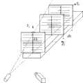
图1是一平行线平板靶标及其拓扑关系;Fig. 1 is a parallel line plate target and its topological relationship;
图2是本发明标定方法标定过程示意图;Fig. 2 is a schematic diagram of the calibration process of the calibration method of the present invention;
图3是图2中所示用于完成CCD摄像机标定的线结构光视觉系统的数学模型;Fig. 3 is shown in Fig. 2 and is used for completing the mathematical model of the line structured light vision system of CCD camera calibration;
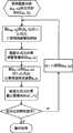
图4是本发明标定方法中标定运算流程图;Fig. 4 is a flow chart of calibration operation in the calibration method of the present invention;
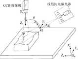
图5是本发明标定方法所用系统的结构方式示意图;Fig. 5 is a schematic diagram of the structure of the system used in the calibration method of the present invention;
图6是CCD摄像机光轴和光平面夹角的确定;Fig. 6 is the determination of the angle between the optical axis of the CCD camera and the light plane;
图7是确定CCD摄像机光轴和光平面夹角的流程图;Fig. 7 is the flow chart that determines CCD camera optical axis and light plane angle;
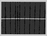
图8-1、图8-2、图8-3、图8-4、图8-5和图8-6是传感器标定的采集图像。Figure 8-1, Figure 8-2, Figure 8-3, Figure 8-4, Figure 8-5 and Figure 8-6 are the collected images of sensor calibration.
具体实施方式Detailed ways
下面结合附图和一具体实施方式详细描述本发明实现的过程。The implementation process of the present invention will be described in detail below in conjunction with the accompanying drawings and a specific embodiment.
步骤一、首先,设计一平行线平板靶标,如图1所示,在其表面刻画有一组具有N条(图1中示出的是10条)水平阵列直线,该N的上限值根据CCD摄像机的视场范围大小确定,将位于中间的一条直线定义为中心线,其上下两侧邻近的两条平行直线与该中心线的距离为ds,称为标记线。以这两条标记线为基准,向上和向下的相邻平行线的间距均为dy,且dy>ds。其中,平行线的条数通常N不少于7条,N的上限数值及ds和dy的取值范围根据传感器的CCD摄像机视场范围决定,所有的水平直线与平行线平板靶标的矩形平板的下边沿平行。Step 1, at first, design a flat plate target with parallel lines, as shown in Figure 1, depict a group of N (shown in Figure 1 is 10) horizontal array straight lines on its surface, the upper limit of this N is according to CCD The size of the field of view of the camera is determined, and a straight line in the middle is defined as the center line, and the distance between the two parallel straight lines adjacent to the upper and lower sides of the center line is ds, which are called marker lines. With these two marked lines as the reference, the spacing between upward and downward adjacent parallel lines is both dy, and dy>ds. Among them, the number of parallel lines is usually N not less than 7. The upper limit value of N and the value range of ds and dy are determined according to the field of view of the CCD camera of the sensor. The bottom edge is parallel.
步骤二、将靶标固定在一个精密移动平台上,固定靶标并使其垂直于平台的移动方向,然后调整平台位置确保靶标平面垂直于光平面。激光平面投射到靶标面上产生一条光条,调整传感器的激光器以保证光条重合于靶标面的上下对齐标记,使光条垂直于靶标上的直线阵列。光条与平行直线阵列相交形成一组交点。如图2所示,标定过程中,以一定的间距dx移动靶标到不同位置并采集一组图像。在每个位置采集一幅图像,如图8-1、图8-2、图8-3、图8-4、图8-5和图8-6所示,并将采集到的图像保存到计算机。Step 2. Fix the target on a precision mobile platform, fix the target and make it perpendicular to the moving direction of the platform, and then adjust the position of the platform to ensure that the target plane is perpendicular to the light plane. The laser plane is projected onto the target surface to generate a light strip, and the laser of the sensor is adjusted to ensure that the light strip coincides with the upper and lower alignment marks on the target surface, so that the light strip is perpendicular to the linear array on the target. The light strips intersect with the array of parallel straight lines to form a set of intersection points. As shown in Figure 2, during the calibration process, the target is moved to different positions with a certain distance dx and a set of images is collected. Collect an image at each position, as shown in Figure 8-1, Figure 8-2, Figure 8-3, Figure 8-4, Figure 8-5, and Figure 8-6, and save the collected images to computer.
步骤三、靶标拓扑关系的确定,即:图像处理,提取光条和各条平行线的交点(即,标定特征点)的图像坐标,并根据靶标的拓扑关系确定它们的光平面坐标系坐标。Step 3. Determination of the topological relationship of the target, namely: image processing, extracting the image coordinates of the intersection points (ie, marked feature points) of the light strip and each parallel line, and determining their light plane coordinate system coordinates according to the topological relationship of the target.
如图1所示,当线结构光光条投射于平行线平板靶标时,光条与各平行线相交,交点定义为标定所需的特征点。光条与中心线的交点定义光平面坐标系的原点Ol,平行线的方向定义为OlZl,光条方向定义为OlYl,OlXl轴垂直于靶标平面。As shown in Figure 1, when the line-structured light strip is projected on the parallel-line flat target, the light strip intersects each parallel line, and the intersection point is defined as the feature point required for calibration. The intersection point of the light bar and the center line defines the origin Ol of the light plane coordinate system, the direction of the parallel line is defined as Ol Zl , the direction of the light bar is defined as Ol Yl , and the Ol Xl axis is perpendicular to the target plane.
定义靶标在CCD摄像机景深之内且距离传感器(由CCD摄像机和激光器以及其机械夹具组成的整体)最近位置时为零位,定义此位置光条和中心直线的交点为世界坐标原点,其坐标为(0,0,0)。由于靶标上各平行直线分布位置确定,而光条与各直线垂直,与各直线的交点在世界坐标系下的OlYl轴线坐标可以确定。例如沿OlYl轴正方向,光条与标记线的交点坐标分别为(0,ds,0),(0,ds+dy,0),(0,ds+2·dy,0),(0,ds+3·dy,0),......。k设为平台移动位置标记,平台的移动形成OlXl坐标,那么靶标在其他位置时交点的轴坐标为(k·dx,Yli,0),这样便获得了各交点(即标定特征点)的世界坐标,并将其保存到计算机。Define the zero position when the target is within the depth of field of the CCD camera and the closest position to the sensor (the whole composed of CCD camera, laser and its mechanical fixture). Define the intersection point of the light bar and the center line at this position as the origin of the world coordinates, and its coordinates are (0,0,0). Since the distribution position of each parallel straight line on the target is determined, and the light strip is perpendicular to each straight line, the Ol Yl axis coordinates of the intersection point with each straight line in the world coordinate system can be determined. For example, along the positive direction of the Ol Yl axis, the intersection coordinates of the light bar and the marking line are (0, ds, 0), (0, ds+dy, 0), (0, ds+2·dy, 0), (0, ds+3·dy, 0), …. k is set as the position mark of the platform movement, and the movement of the platform forms Ol Xl coordinates, then the axis coordinates of the intersection points when the target is in other positions are (k dx, Yli , 0), so that each intersection point (that is, the calibration feature point) and save it to the computer.
步骤四、根据图4的流程,完成传感器参数的标定,将标定结果保存到计算机。Step 4. According to the flow chart in FIG. 4 , complete the calibration of the sensor parameters, and save the calibration results to the computer.
线结构光视觉测量模型如图3所示,(Xl,Yl,0)为光平面上P点在光平面坐标系下的三维坐标,(u,v)和(ud,vd)分别为理想像点Pu和实际像点Pd在计算机图像坐标系下的像素坐标,根据直接线性变换模型(Direct Linear Transformation,DLT),P(Xl,Yl,0)与(u,v)的转换关系如下:The line structured light vision measurement model is shown in Figure 3, (Xl , Yl , 0) is the three-dimensional coordinates of point P on the light plane in the light plane coordinate system, (u, v) and (ud , vd ) are respectively the pixel coordinates of the ideal image point Pu and the actual image point Pd in the computer image coordinate system, according to the direct linear transformation model (Direct Linear Transformation, DLT), P(Xl , Yl , 0) and (u, v) The conversion relationship is as follows:
上述公式(1)中,矩阵M为传感器参数矩阵。In the above formula (1), the matrix M is the sensor parameter matrix.
畸变修正模型定义为:The distortion correction model is defined as:
公式(2)中,ki和pi(i=0,1,2...,9)为畸变模型参数。In formula (2),ki andpi (i=0, 1, 2..., 9) are distortion model parameters.
在标定过程中,设有N个(本实施例中是10个)用于标定的特征点,它们的理想图像坐标和实际图像坐标分别为(ui,vi)和(udi,vdi),其光平面坐标系坐标为(Xli,Yli)。During the calibration process, there are N (10 in this embodiment) feature points for calibration, and their ideal image coordinates and actual image coordinates are (ui , vi ) and (udi , vdi ), and its light plane coordinate system coordinates are (Xli , Yli ).
传感器标定运算具体过程为:The specific process of sensor calibration operation is as follows:
1)通过图像处理获得标定特征点的实际图像坐标(udi,vdi)和光平面坐标(Xli,Yli);1) Obtain the actual image coordinates (udi , vdi ) and light plane coordinates (Xli , Yli ) of the marked feature points through image processing;
2)将(udi,vdi)和(Xli,Yli)代入公式(1)得到模型转换的参数矩阵M中的各元素的值;2) Substituting (udi , vdi ) and (Xli , Yli ) into formula (1) to obtain the value of each element in the parameter matrix M of model transformation;
3)利用(Xli,Yli)和得到的矩阵M,根据公式(1)计算理想图像坐标(ui,vi);3) Using (Xli , Yli ) and the obtained matrix M, calculate the ideal image coordinates (ui , vi ) according to the formula (1);
4)将(udi,vdi)和(ui,vi)代入公式(2)得到畸变模型的畸变模型参数ki和pi的值;4) Substituting (udi , vdi ) and (ui , vi ) into formula (2) to obtain the values of distortion model parameters ki and pi of the distortion model;
5)将(udi,vdi)及得到的ki和pi代入公式(2),计算修正的图像坐标(ui’,vi’);5) Substitute (udi , vdi ) and the obtained ki andp iinto formula (2), and calculate the corrected image coordinates (ui ', vi ');
6)设定迭代求解过程结束条件,用于判断是否达到精度要求,其迭代求解过程结束条件如下列公式(3):6) Set the end condition of the iterative solution process to judge whether the accuracy requirement is met, and the end condition of the iterative solution process is as the following formula (3):
如果达到上述公式(3)所限定的条件要求,则结束计算过程,输出结果;否则,用(ui’,vi’)更新(udi,vdi),回跳到如图4所示的第一步顺序执行。其具体流程如图4所示。If the conditional requirements defined by the above formula (3) are met, the calculation process is ended and the result is output; otherwise, (udi , vdi ) is updated with (ui ', v i' ), and the jump back is shown in Figure 4 The first steps are executed sequentially. Its specific process is shown in Figure 4.
步骤五、根据图5的流程,确定CCD摄像机光轴与光平面的夹角。Step 5. Determine the angle between the optical axis of the CCD camera and the optical plane according to the flow chart in FIG. 5 .
传感器参数标定完成之后,可先根据公式(3)将图像处理得到的点P对应的光条点进行畸变修正得到其理想图像坐标(u,v),进而可根据下式求得该点的光平面坐标系坐标(Xl,Yl):After the calibration of the sensor parameters is completed, the light stripe point corresponding to the point P obtained by image processing can be corrected according to the formula (3) to obtain its ideal image coordinates (u, v), and then the light stripe point of the point can be obtained according to the following formula Plane coordinate system coordinates (Xl , Yl ):
公式(4)中,In formula (4),
n11=m31m24-m21m34, n12=m11m34-m14m31, n13=m21m14-m11m24;n11 =m31 m24 -m21 m34 , n12 =m11 m34 -m14 m31 , n13 =m21 m14 -m11 m24 ;
n21=m22m34-m32m24, n22=m32m14-m12m34, n23=m12m24-m22m14;n21 =m22 m34 -m32 m24 , n22 =m32 m14 -m12 m34 , n23 =m12 m24 -m22 m14 ;
n31=m21m32-m31m22, n32=m31m12-m11m32, n33=m11m22-m21m12n31 =m21 m32 -m31 m22 , n32 =m31 m12 -m11 m32 , n33 =m11 m22 -m21 m12
线结构光视觉测量技术用于微小三维尺寸扫描测量时,系统的结构设计及布局一般是:传感器的CCD摄像机垂直于被测物体表面,传感器的激光器以一定的角度(如图5中所示为θ角)投射线结构光到被测物体表面,如图5所示。测量世界坐标系为Ow-XwYwZw,其中OwXw轴平行于CCD摄像机的光轴OcZc,OwYw轴平行于光平面坐标系的OlYl轴,根据右手定则确定OwZw轴,被测物体表面点P在OwZw轴方向上的坐标由平移台带动物体移动的距离决定。When the line-structured light vision measurement technology is used for scanning measurement of small three-dimensional dimensions, the structural design and layout of the system are generally: the CCD camera of the sensor is perpendicular to the surface of the measured object, and the laser of the sensor is at a certain angle (as shown in Figure 5). θ angle) project line structured light onto the surface of the measured object, as shown in Figure 5. The measurement world coordinate system is Ow -Xw Yw Zw , where the Ow Xw axis is parallel to the optical axis Oc Zc of the CCD camera, and the Ow Yw axis is parallel to the Ol Yl axis of the light plane coordinate system , according to the right-hand rule to determine the Ow Zw axis, the coordinates of the surface point P of the measured object in the direction of the Ow Zw axis are determined by the distance that the translation table moves the object.
因此需要确定CCD摄像机光轴与光平面的夹角θ,即OwXw轴与OlXl轴的夹角。从而根据下列公式(5),利用点P的光平面坐标系坐标(Xl,Yl)得到其世界坐标系坐标(Xw,Yw):Therefore, it is necessary to determine the angle θ between the optical axis of the CCD camera and the light plane, that is, the angle between the OwXw axis and the Ol Xl axis. Therefore, according to the following formula (5), use the light plane coordinate system coordinates (Xl , Yl ) of point P to obtain its world coordinate system coordinates (Xw , Yw ):
该夹角θ的标定方法如图6所示,具体流程如图7所示;The calibration method of the included angle θ is shown in Figure 6, and the specific process is shown in Figure 7;
(1)将平板靶标垂直于光轴OcZc放置于CCD摄像机视场范围之内,在CCD摄像机景深范围内任何一处(图6中所示的第一位置)处采集光条图像处理获得其各点的图像坐标(udi,vdi),利用公式(2)和(4)计算得到对应的光平面坐标(Xli,Yli),对其进行直线拟合,得到该处的空间直线;(1) Place the flat plate target perpendicular to the optical axis Oc Zc within the field of view of the CCD camera, collect the light strip image at any place within the depth of field of the CCD camera (the first position shown in Figure 6) Obtain the image coordinates (udi , vdi ) of each point, use formulas (2) and (4) to calculate the corresponding light plane coordinates (Xli , Yli ), and perform straight line fitting on them to obtain the straight line in space;
(2)将平面靶标平移距离DT至CCD摄像机景深范围另一位置(图6中所示第二位置)处采集光条图像,采用上一步同样的方式得到该处空间直线,计算两条空间直线的距离DL;(2) Translate the plane target by a distance DT to another position within the depth of field of the CCD camera (the second position shown in Figure 6) to collect the light strip image, use the same method as the previous step to obtain the space straight line at this position, and calculate the two spaces the straight line distance DL ;
(3)根据下列公式(6)计算得到夹角θ的值:(3) Calculate the value of the included angle θ according to the following formula (6):
cosθ=DT/DL (6)cosθ=DT /DL (6)
标定得到的夹角θ=43.575°,传感器参数如表1所示,畸变模型参数如表2所示,至此完成了传感器标定,将结果保存到计算机。The included angle obtained by calibration is θ=43.575°, the sensor parameters are shown in Table 1, and the distortion model parameters are shown in Table 2. So far, the sensor calibration is completed, and the results are saved to the computer.
表1.传感器参数Table 1. Sensor parameters

表2.畸变模型参数Table 2. Distortion model parameters
本发明标定方法适用于微小尺寸测量的线结构光视觉传感器标定任务,可替代现有的线结构光视觉传感器的标定方法,可应用于现场标定,能够满足线结构光视觉高精度检测任务的需要。The calibration method of the present invention is suitable for the calibration task of the linear structured light vision sensor for micro-size measurement, can replace the existing calibration method of the linear structured light visual sensor, can be applied to on-site calibration, and can meet the needs of the high-precision detection task of the linear structured light vision .
尽管上面结合图对本发明进行了描述,但是本发明并不局限于上述的具体实施方式,上述的具体实施方式仅仅是示意性的,而不是限制性的,本领域的普通技术人员在本发明的启示下,在不脱离本发明宗旨的情况下,还可以作出很多变形,这些均属于本发明的保护之内。Although the present invention has been described above in conjunction with the drawings, the present invention is not limited to the above-mentioned specific embodiments, and the above-mentioned specific embodiments are only illustrative, rather than restrictive. Under the inspiration, many modifications can be made without departing from the gist of the present invention, and these all belong to the protection of the present invention.
Claims (1)
Priority Applications (1)
| Application Number | Priority Date | Filing Date | Title |
|---|---|---|---|
| CN201010146165ACN101814185B (en) | 2010-04-14 | 2010-04-14 | Line structured light vision sensor calibration method for micro-size measurement |
Applications Claiming Priority (1)
| Application Number | Priority Date | Filing Date | Title |
|---|---|---|---|
| CN201010146165ACN101814185B (en) | 2010-04-14 | 2010-04-14 | Line structured light vision sensor calibration method for micro-size measurement |
Publications (2)
| Publication Number | Publication Date |
|---|---|
| CN101814185Atrue CN101814185A (en) | 2010-08-25 |
| CN101814185B CN101814185B (en) | 2012-10-10 |
Family
ID=42621432
Family Applications (1)
| Application Number | Title | Priority Date | Filing Date |
|---|---|---|---|
| CN201010146165AExpired - Fee RelatedCN101814185B (en) | 2010-04-14 | 2010-04-14 | Line structured light vision sensor calibration method for micro-size measurement |
Country Status (1)
| Country | Link |
|---|---|
| CN (1) | CN101814185B (en) |
Cited By (22)
| Publication number | Priority date | Publication date | Assignee | Title |
|---|---|---|---|---|
| CN102589476A (en)* | 2012-02-13 | 2012-07-18 | 天津大学 | High-speed scanning and overall imaging three-dimensional (3D) measurement method |
| CN102750698A (en)* | 2012-06-11 | 2012-10-24 | 上海大学 | Texture camera calibration device, texture camera calibration method and geometry correction method of texture image of texture camera |
| CN102901464A (en)* | 2012-10-18 | 2013-01-30 | 扬州万福压力容器有限公司 | Alignment method of kettle-like equipment |
| CN103559707A (en)* | 2013-10-30 | 2014-02-05 | 同济大学 | Industrial fixed-focus camera parameter calibration method based on moving square target calibration object |
| CN103884271A (en)* | 2012-12-20 | 2014-06-25 | 中国科学院沈阳自动化研究所 | Direct calibration method for line structured light vision sensor |
| CN104616325A (en)* | 2015-01-21 | 2015-05-13 | 大连理工大学 | Rapid and high-precision method for extracting light strip center on large surface |
| CN105783711A (en)* | 2014-12-09 | 2016-07-20 | 财团法人工业技术研究院 | Three-dimensional scanner correction system and correction method thereof |
| CN106441099A (en)* | 2016-10-13 | 2017-02-22 | 北京交通大学 | Multi-line structure light sensor calibration method |
| CN107101582A (en)* | 2017-07-03 | 2017-08-29 | 吉林大学 | Axial workpiece run-out error On-line Measuring Method based on structure light vision |
| CN107462174A (en)* | 2017-06-19 | 2017-12-12 | 北京交通大学 | The method and device of the proportion of utilization factor and frame difference measurements contact net geometric parameter |
| CN108337407A (en)* | 2017-01-19 | 2018-07-27 | 株式会社Rf | Photographing device, accessory of photographing device, and image processing method |
| CN108428251A (en)* | 2018-03-09 | 2018-08-21 | 深圳市中捷视科科技有限公司 | One kind being based on machine vision technique laser structure light automatic calibration method |
| CN109443209A (en)* | 2018-12-04 | 2019-03-08 | 四川大学 | A kind of line-structured light system calibrating method based on homography matrix |
| CN109682304A (en)* | 2019-02-02 | 2019-04-26 | 北京理工大学 | A kind of composition error modeling method based on CCD camera contraposition assembly system |
| CN110118528A (en)* | 2019-04-29 | 2019-08-13 | 天津大学 | A kind of line-structured light scaling method based on chessboard target |
| CN111336948A (en)* | 2020-03-02 | 2020-06-26 | 武汉理工大学 | Non-calibrated handheld profile detection method and device based on imaging plane conversion |
| WO2021093111A1 (en)* | 2019-11-15 | 2021-05-20 | 五邑大学 | Fully automatic calibration method and apparatus for structured light 3d visual system |
| CN112945109A (en)* | 2021-01-26 | 2021-06-11 | 西安交通大学 | Laser displacement meter array system parameter calibration method based on horizontal displacement table |
| CN113847874A (en)* | 2021-08-20 | 2021-12-28 | 天津大学 | Vision-based displacement direction calibration method for displacement table |
| CN113983933A (en)* | 2021-11-11 | 2022-01-28 | 易思维(杭州)科技有限公司 | Calibration method of multi-line laser sensor |
| CN114111576A (en)* | 2021-11-24 | 2022-03-01 | 易思维(杭州)科技有限公司 | Aircraft skin clearance surface difference detection method and sensor |
| CN114241061A (en)* | 2021-12-24 | 2022-03-25 | 上海柏楚电子科技股份有限公司 | Calibration method, calibration system and calibration target for line structured light imaging and measurement system using calibration target |
Citations (5)
| Publication number | Priority date | Publication date | Assignee | Title |
|---|---|---|---|---|
| JP2004241449A (en)* | 2003-02-04 | 2004-08-26 | National Institute Of Advanced Industrial & Technology | Solar cell performance evaluation device and performance evaluation method |
| CN101109620A (en)* | 2007-09-05 | 2008-01-23 | 北京航空航天大学 | A method for calibrating structural parameters of a structured light vision sensor |
| CN101419708A (en)* | 2008-12-08 | 2009-04-29 | 北京航空航天大学 | Structure optical parameter demarcating method based on one-dimensional target drone |
| CN101493318A (en)* | 2008-09-16 | 2009-07-29 | 北京航空航天大学 | Rudder deflection angle synchronization dynamic measurement system and implementing method thereof |
| CN101526336A (en)* | 2009-04-20 | 2009-09-09 | 陈炳生 | Calibration method of linear structured light three-dimensional visual sensor based on measuring blocks |
- 2010
- 2010-04-14CNCN201010146165Apatent/CN101814185B/ennot_activeExpired - Fee Related
Patent Citations (5)
| Publication number | Priority date | Publication date | Assignee | Title |
|---|---|---|---|---|
| JP2004241449A (en)* | 2003-02-04 | 2004-08-26 | National Institute Of Advanced Industrial & Technology | Solar cell performance evaluation device and performance evaluation method |
| CN101109620A (en)* | 2007-09-05 | 2008-01-23 | 北京航空航天大学 | A method for calibrating structural parameters of a structured light vision sensor |
| CN101493318A (en)* | 2008-09-16 | 2009-07-29 | 北京航空航天大学 | Rudder deflection angle synchronization dynamic measurement system and implementing method thereof |
| CN101419708A (en)* | 2008-12-08 | 2009-04-29 | 北京航空航天大学 | Structure optical parameter demarcating method based on one-dimensional target drone |
| CN101526336A (en)* | 2009-04-20 | 2009-09-09 | 陈炳生 | Calibration method of linear structured light three-dimensional visual sensor based on measuring blocks |
Cited By (36)
| Publication number | Priority date | Publication date | Assignee | Title |
|---|---|---|---|---|
| CN102589476B (en)* | 2012-02-13 | 2014-04-02 | 天津大学 | High-speed scanning and overall imaging three-dimensional (3D) measurement method |
| CN102589476A (en)* | 2012-02-13 | 2012-07-18 | 天津大学 | High-speed scanning and overall imaging three-dimensional (3D) measurement method |
| CN102750698A (en)* | 2012-06-11 | 2012-10-24 | 上海大学 | Texture camera calibration device, texture camera calibration method and geometry correction method of texture image of texture camera |
| CN102750698B (en)* | 2012-06-11 | 2014-12-03 | 上海大学 | Texture camera calibration device, texture camera calibration method and geometry correction method of texture image of texture camera |
| CN102901464A (en)* | 2012-10-18 | 2013-01-30 | 扬州万福压力容器有限公司 | Alignment method of kettle-like equipment |
| CN102901464B (en)* | 2012-10-18 | 2015-03-25 | 扬州万福压力容器有限公司 | Alignment method of kettle-like equipment |
| CN103884271B (en)* | 2012-12-20 | 2016-08-17 | 中国科学院沈阳自动化研究所 | A kind of line structured light vision sensor direct calibration method |
| CN103884271A (en)* | 2012-12-20 | 2014-06-25 | 中国科学院沈阳自动化研究所 | Direct calibration method for line structured light vision sensor |
| CN103559707A (en)* | 2013-10-30 | 2014-02-05 | 同济大学 | Industrial fixed-focus camera parameter calibration method based on moving square target calibration object |
| CN103559707B (en)* | 2013-10-30 | 2016-04-20 | 同济大学 | Based on the industrial fixed-focus camera parameter calibration method of motion side's target earnest |
| CN105783711A (en)* | 2014-12-09 | 2016-07-20 | 财团法人工业技术研究院 | Three-dimensional scanner correction system and correction method thereof |
| CN104616325B (en)* | 2015-01-21 | 2018-02-16 | 大连理工大学 | A kind of large surfaces Light stripes center extraction method of quick high accuracy |
| CN104616325A (en)* | 2015-01-21 | 2015-05-13 | 大连理工大学 | Rapid and high-precision method for extracting light strip center on large surface |
| CN106441099A (en)* | 2016-10-13 | 2017-02-22 | 北京交通大学 | Multi-line structure light sensor calibration method |
| CN106441099B (en)* | 2016-10-13 | 2019-04-05 | 北京交通大学 | The scaling method of multiple line structure optical sensor |
| CN108337407A (en)* | 2017-01-19 | 2018-07-27 | 株式会社Rf | Photographing device, accessory of photographing device, and image processing method |
| CN108337407B (en)* | 2017-01-19 | 2020-06-16 | 株式会社Rf | Imaging device, imaging device accessory, and image processing method |
| CN107462174B (en)* | 2017-06-19 | 2019-06-21 | 北京交通大学 | Method and device for measuring geometrical parameters of catenary by using scale factor and frame difference |
| CN107462174A (en)* | 2017-06-19 | 2017-12-12 | 北京交通大学 | The method and device of the proportion of utilization factor and frame difference measurements contact net geometric parameter |
| CN107101582A (en)* | 2017-07-03 | 2017-08-29 | 吉林大学 | Axial workpiece run-out error On-line Measuring Method based on structure light vision |
| CN108428251A (en)* | 2018-03-09 | 2018-08-21 | 深圳市中捷视科科技有限公司 | One kind being based on machine vision technique laser structure light automatic calibration method |
| CN109443209A (en)* | 2018-12-04 | 2019-03-08 | 四川大学 | A kind of line-structured light system calibrating method based on homography matrix |
| CN109443209B (en)* | 2018-12-04 | 2019-12-31 | 四川大学 | A Calibration Method of Line Structured Light System Based on Homography Matrix |
| CN109682304A (en)* | 2019-02-02 | 2019-04-26 | 北京理工大学 | A kind of composition error modeling method based on CCD camera contraposition assembly system |
| CN110118528B (en)* | 2019-04-29 | 2020-11-06 | 天津大学 | A method of line structure light positioning based on chessboard target |
| CN110118528A (en)* | 2019-04-29 | 2019-08-13 | 天津大学 | A kind of line-structured light scaling method based on chessboard target |
| US12002241B2 (en) | 2019-11-15 | 2024-06-04 | Wuyi University | Full-automatic calibration method and apparatus oriented to structured light 3D vision system |
| WO2021093111A1 (en)* | 2019-11-15 | 2021-05-20 | 五邑大学 | Fully automatic calibration method and apparatus for structured light 3d visual system |
| CN111336948A (en)* | 2020-03-02 | 2020-06-26 | 武汉理工大学 | Non-calibrated handheld profile detection method and device based on imaging plane conversion |
| CN111336948B (en)* | 2020-03-02 | 2021-11-02 | 武汉理工大学 | Non-calibrated handheld profile detection method and device based on imaging plane conversion |
| CN112945109A (en)* | 2021-01-26 | 2021-06-11 | 西安交通大学 | Laser displacement meter array system parameter calibration method based on horizontal displacement table |
| CN113847874A (en)* | 2021-08-20 | 2021-12-28 | 天津大学 | Vision-based displacement direction calibration method for displacement table |
| CN113983933A (en)* | 2021-11-11 | 2022-01-28 | 易思维(杭州)科技有限公司 | Calibration method of multi-line laser sensor |
| CN113983933B (en)* | 2021-11-11 | 2022-04-19 | 易思维(杭州)科技有限公司 | Calibration method of multi-line laser sensor |
| CN114111576A (en)* | 2021-11-24 | 2022-03-01 | 易思维(杭州)科技有限公司 | Aircraft skin clearance surface difference detection method and sensor |
| CN114241061A (en)* | 2021-12-24 | 2022-03-25 | 上海柏楚电子科技股份有限公司 | Calibration method, calibration system and calibration target for line structured light imaging and measurement system using calibration target |
Also Published As
| Publication number | Publication date |
|---|---|
| CN101814185B (en) | 2012-10-10 |
Similar Documents
| Publication | Publication Date | Title |
|---|---|---|
| CN101814185A (en) | Line structured light vision sensor calibration method for micro-size measurement | |
| CN101943563B (en) | Rapid calibration method of line-structured light vision sensor based on space plane restriction | |
| CN105678785B (en) | A kind of laser and the scaling method of camera relative pose relation | |
| CN104266608B (en) | Field calibration device for visual sensor and calibration method | |
| CN103411553B (en) | The quick calibrating method of multi-linear structured light vision sensors | |
| CN105066877B (en) | Tree measurement method based on intelligent terminal camera lens | |
| CN103530880B (en) | Based on the camera marking method of projection Gaussian network pattern | |
| CN105025290B (en) | A kind of inclined method between adjust automatically camera module sensor and camera lens | |
| CN114018932B (en) | Measuring Method of Pavement Disease Index Based on Rectangular Calibration Object | |
| CN103558850A (en) | Laser vision guided welding robot full-automatic movement self-calibration method | |
| CN103528520B (en) | Based on pick-up unit and the method for the synchronous operation jack-up system of binocular vision | |
| CN107256568A (en) | A kind of high-accuracy mechanical arm trick camera calibration method and calibration system | |
| CN101750051A (en) | Visual navigation based multi-crop row detection method | |
| CN106600647A (en) | Binocular visual multi-line projection structured light calibration method | |
| CN104729481B (en) | Cooperative target pose precision measurement method based on PNP perspective model | |
| CN101813469A (en) | Method for measuring leaf area by manually shooting | |
| CN110110797B (en) | Water surface target training set automatic acquisition method based on multi-sensor fusion | |
| CN206863817U (en) | Camera review automatic acquisition device and camera calibration systems | |
| CN101968877A (en) | Coded mark point design method for double-layer arc | |
| CN115187612B (en) | A plane area measurement method, device and system based on machine vision | |
| CN103747196B (en) | A Projection Method Based on Kinect Sensor | |
| CN101561262A (en) | Surface roughness on line measurement method under uncertain condition | |
| CN115100126B (en) | An intelligent perception method for plane displacement field of bridge structure | |
| CN103927748B (en) | A kind of coordinate scaling method based on many rectangular images distance transformation model | |
| CN105574812A (en) | Multi-angle three-dimensional data registration method and device |
Legal Events
| Date | Code | Title | Description |
|---|---|---|---|
| C06 | Publication | ||
| PB01 | Publication | ||
| SE01 | Entry into force of request for substantive examination | ||
| C14 | Grant of patent or utility model | ||
| GR01 | Patent grant | ||
| C17 | Cessation of patent right | ||
| CF01 | Termination of patent right due to non-payment of annual fee | Granted publication date:20121010 Termination date:20130414 |