CN101813590B - Testing device and method for reliability evaluation of mechanical component of micro-electromechanical system - Google Patents
Testing device and method for reliability evaluation of mechanical component of micro-electromechanical systemDownload PDFInfo
- Publication number
- CN101813590B CN101813590BCN2009100785627ACN200910078562ACN101813590BCN 101813590 BCN101813590 BCN 101813590BCN 2009100785627 ACN2009100785627 ACN 2009100785627ACN 200910078562 ACN200910078562 ACN 200910078562ACN 101813590 BCN101813590 BCN 101813590B
- Authority
- CN
- China
- Prior art keywords
- micro
- environmental chamber
- mechanical component
- electromechanical system
- environmental
- Prior art date
- Legal status (The legal status is an assumption and is not a legal conclusion. Google has not performed a legal analysis and makes no representation as to the accuracy of the status listed.)
- Expired - Fee Related
Links
Images


Landscapes
- Micromachines (AREA)
- Testing Resistance To Weather, Investigating Materials By Mechanical Methods (AREA)
Abstract
Translated fromChinese
Description
Translated fromChinese技术领域technical field
本发明涉及微机电系统,是用于微机电系统机械组元可靠性评估的测试装置和测试方法。The invention relates to a micro-electro-mechanical system, which is a testing device and a testing method for evaluating the reliability of mechanical components of the micro-electro-mechanical system.
背景技术Background technique
微机电系统(Micro Electromechanical System,MEMS)是指集微型传感器、执行器、信号处理与控制电路、接口电路和电源等于一体的微型机电系统。MEMS具有微型化、智能化、多功能、高集成度和适于大批量生产等优点,因此在汽车、通信、生物医学、消费产品、航空航天和国防等领域都具有广泛的应用前景。Micro Electromechanical System (MEMS) refers to a micro electromechanical system that integrates micro sensors, actuators, signal processing and control circuits, interface circuits and power supplies. MEMS has the advantages of miniaturization, intelligence, multi-function, high integration and suitable for mass production, so it has broad application prospects in the fields of automobile, communication, biomedicine, consumer products, aerospace and national defense.
微机电系统研究的最终目标是用快速发展的微纳加工技术和成熟的CMOS工艺使传感器和传动器小型化、更灵敏、低能耗及空间排布更致密。但是,就像30多年前的集成电路产业一样,当前MEMS产业发展仍然很不成熟,而原型微纳器件能否顺利实现产业化所面临的最大挑战是可靠性问题。The ultimate goal of MEMS research is to use the rapidly developing micro-nano processing technology and mature CMOS technology to make sensors and actuators miniaturized, more sensitive, low energy consumption and more densely spaced. However, just like the integrated circuit industry more than 30 years ago, the current development of the MEMS industry is still very immature, and the biggest challenge facing the successful industrialization of prototype micro-nano devices is the issue of reliability.
可靠性是指一个组元、器件或系统在特定的环境条件下正常工作,在给定时间内能够完成所期望的任务的几率。MEMS可靠性研究直接关系到MEMS产品的开发效率、成本和产业化进程。通过研究MEMS器件的失效模式并澄清其失效机理,可改进并提高MEMS器件的可靠性。因此,MEMS可靠性研究是当前MEMS领域一项迫切任务。人们对微纳器件可靠性了解甚少有两个根本原因,首先,微纳器件在传统的微电子器件组元,即电组元之外,还包含有大量承载或可移动的机械组元;虽然能够借鉴人们在电学可靠性方面几十年来积累的研究成果,但是微纳器件机械可靠性研究相对来说仍然是一个空白。其次,由于维度和尺度效应,基于一些宏观假设建立起来的传统大尺度样品机械可靠性的数据并不适用于微纳器件。因此,迫切需要开发微纳器件机械可靠性评估方法、建立测试平台,从而推动国内微纳器件研究和产业化发展。Reliability refers to the probability that a component, device or system can work normally under specific environmental conditions and can complete the expected task within a given time. MEMS reliability research is directly related to the development efficiency, cost and industrialization process of MEMS products. By studying the failure modes of MEMS devices and clarifying their failure mechanisms, the reliability of MEMS devices can be improved and enhanced. Therefore, MEMS reliability research is an urgent task in the current MEMS field. There are two basic reasons why people know little about the reliability of micro-nano devices. First, micro-nano devices contain a large number of load-bearing or movable mechanical components in addition to traditional microelectronic device components, that is, electrical components; Although it is possible to learn from the research results accumulated by people in the field of electrical reliability for decades, the research on the mechanical reliability of micro-nano devices is still relatively blank. Secondly, due to dimensionality and scale effects, the data on the mechanical reliability of traditional large-scale samples based on some macroscopic assumptions are not applicable to micro-nano devices. Therefore, there is an urgent need to develop a mechanical reliability evaluation method for micro-nano devices and establish a test platform, so as to promote the research and industrialization of domestic micro-nano devices.
MEMS机械组元的可靠性研究目前存在以下主要问题:The reliability research of MEMS mechanical components currently has the following main problems:
1、微纳器件种类繁多、应用广泛,这对可靠性测试提出了艰巨的挑战。概括起来,MEMS/NEMS器件中的基本结构有悬臂梁(cantilever)、桥、膜片(membrane)、铰链(hinge)、空腔(cavity)、齿轮等,尽管它们有不同的应用,但是其失效机理大多类似。MEMS机械组元可靠性测试装置要求除了可以进行相关电学测试外,还应具备机械性能测试能力,微结构形貌观察与分析能力,以及较强的数据分析与处理能力。1. There are various types and applications of micro-nano devices, which pose a difficult challenge to reliability testing. To sum up, the basic structures in MEMS/NEMS devices include cantilever, bridge, membrane, hinge, cavity, gear, etc. Although they have different applications, their failure The mechanisms are mostly similar. The MEMS mechanical component reliability test device requires that in addition to relevant electrical tests, it should also have mechanical performance test capabilities, microstructure morphology observation and analysis capabilities, and strong data analysis and processing capabilities.
2、MEMS机械组元的可靠性以及失效模式与工作环境密切相关,因此,MEMS机械组元可靠性测试装置要求能实现不同的环境条件,以研究温度、湿度、气氛、气压等环境因素对MEMS器件可靠性和寿命的影响,建立一个适用于微纳器件的可控环境工作平台,实现微纳器件及其结构材料的机械性能、可靠性、寿命测试。2. The reliability and failure modes of MEMS mechanical components are closely related to the working environment. Therefore, the reliability test device for MEMS mechanical components requires different environmental conditions to study the effects of environmental factors such as temperature, humidity, atmosphere, and air pressure on MEMS. The influence of device reliability and life, establish a controllable environment work platform suitable for micro-nano devices, and realize the mechanical properties, reliability and life tests of micro-nano devices and their structural materials.
要解决上述问题,MEMS机械组元可靠性测试装置的研制开发需要建立可对测试环境进行控制的环境腔室,环境腔室应与光学测量装置集成。此外,环境腔室还应实现环境条件:温度、气压、可控气氛、湿度调节和机械震动与冲击。To solve the above problems, the research and development of MEMS mechanical component reliability test equipment needs to establish an environmental chamber that can control the test environment, and the environmental chamber should be integrated with the optical measurement device. In addition, the environmental chamber should also realize the environmental conditions: temperature, air pressure, controlled atmosphere, humidity regulation and mechanical vibration and shock.
目前,与微纳器件机械失效机理相关的研究开展得非常少。多数已报道的器件可靠性表征方法都是针对具体器件而独立发展的,不具有普遍性。如美国Texas Instruments(TI)公司研究了数字微镜(Digital Micro-mirror Device)中金属的蠕动和疲劳失效;美国Sandia National Laboratory研究了包含滑动和转动组中金属的蠕动和疲劳失效。国内微纳器件的研究起步较晚,已进入产业化阶段的器件还不多,关于材料和器件可靠性的研究进行得也比较少。东南大学教育部MEMS重点实验室和中科院力学所分别开展过外力冲击下悬臂梁结构和加速度传感器的可靠性研究工作,但是都主要集中在了理论模拟分析,没有见到开发出实际的器件可靠性技术报道。At present, there are very few studies related to the mechanical failure mechanism of micro-nano devices. Most of the reported device reliability characterization methods are independently developed for specific devices and are not universal. For example, Texas Instruments (TI) of the United States has studied the creep and fatigue failure of metals in Digital Micro-mirror Devices; the Sandia National Laboratory of the United States has studied the creep and fatigue failure of metals in sliding and rotating groups. Domestic research on micro-nano devices started relatively late, and there are not many devices that have entered the stage of industrialization, and research on the reliability of materials and devices is also relatively small. The MEMS Key Laboratory of the Ministry of Education of Southeast University and the Institute of Mechanics of the Chinese Academy of Sciences have carried out research on the reliability of cantilever beam structures and acceleration sensors under external force impacts, but they have mainly focused on theoretical simulation analysis, and have not seen the development of actual device reliability. Technical report.
因本研究内容在国际上尚处于起步阶段,国内尚没有开展此方面的研究工作,没有查到相关专利情况。Because the content of this research is still in its infancy internationally, no domestic research work has been carried out in this area, and no relevant patents have been found.
国内外对MEMS机械组元的可靠性测试进行了一些初步的探索并取得了一定的研究成果,但建立通用性、自动化和集成光学测量的MEMS机械组元可靠性测试装置仍面临很多挑战,目前还没出现相关的商业测试仪器。这里申请专利保护的微纳器件通用测试平台的组建将为澄清微纳器件中可动组元的失效机理,为建立MEMS/NEMS薄膜材料和器件的机械可靠性的数据库提供技术支撑,为改善和提高MEMS器件的可靠性和寿命提供指导,推进我国微纳器件可靠性评估技术的发展。At home and abroad, some preliminary explorations have been made on the reliability testing of MEMS mechanical components and some research results have been achieved. However, there are still many challenges in establishing a reliability testing device for MEMS mechanical components that is versatile, automated and integrated with optical measurement. There is no relevant commercial test instrument yet. The establishment of the general test platform for micro-nano devices for patent protection here will clarify the failure mechanism of movable components in micro-nano devices, provide technical support for the establishment of a database of mechanical reliability of MEMS/NEMS thin film materials and devices, and provide technical support for improving and Provide guidance to improve the reliability and life of MEMS devices, and promote the development of reliability evaluation technology for micro-nano devices in my country.
发明内容Contents of the invention
有鉴于此,本发明将光学测量技术、精确环境控制技术和计算机虚拟仪器技术有机结合构成一种用于微机电系统机械组元可靠性评估的测试装置并提出相应的测试方法,可以完成微机电系统机械组元的可靠性测试和失效机理分析。In view of this, the present invention organically combines optical measurement technology, precise environment control technology and computer virtual instrument technology to form a test device for reliability evaluation of mechanical components of MEMS and proposes corresponding test methods, which can complete MEMS Reliability testing and failure mechanism analysis of system mechanical components.
为达到上述目的,本发明提供一种微机电系统机械组元可靠性评估的测试装置,其特征在于,该装置包括:In order to achieve the above object, the present invention provides a test device for evaluating the reliability of mechanical components of MEMS, characterized in that the device includes:
一光学测量单元,用于测量微机电系统机械组元的轮廓曲线,获得被测微机电系统机械组元在失效前后的三维形貌信息或动态位移信息;An optical measurement unit, used to measure the profile curve of the mechanical components of the MEMS, and obtain the three-dimensional shape information or dynamic displacement information of the mechanical components of the measured MEMS before and after failure;
一环境腔室,用于放置被测微机电系统机械组元,并实现微机电系统机械组元可靠性测试所需的各种环境条件,所述各种环境条件包括真空、气压、气氛、温度和湿度;An environmental chamber, which is used to place the mechanical components of the MEMS to be tested, and realize various environmental conditions required for reliability testing of the mechanical components of the MEMS, and the various environmental conditions include vacuum, air pressure, atmosphere, temperature and humidity;
一XY工作台,环境腔室放置在XY工作台上,可跟随XY工作台在水平面内移动,环境腔室的质量低于XY工作台正常工作的载荷限制;An XY workbench, the environmental chamber is placed on the XY workbench, and can follow the XY worktable to move in the horizontal plane, and the quality of the environmental chamber is lower than the load limit of the XY workbench for normal operation;
一环境控制与测量单元,保证在环境腔室内实现所需的各种环境条件并测量相应的环境参数;An environmental control and measurement unit, which ensures the realization of various environmental conditions required in the environmental chamber and measures corresponding environmental parameters;
一数据采集和控制单元,用于控制XY工作台,并带动环境腔室在水平面内移动;环境控制与测量单元,实现与测量各种环境条件。A data acquisition and control unit is used to control the XY workbench and drive the environmental chamber to move in the horizontal plane; an environmental control and measurement unit is used to realize and measure various environmental conditions.
其中还包括一激励单元和电学测量单元,该激励单元和电学测量单元受数据采集和控制单元控制,为被测微机电系统机械组元提供激励信号,数据采集和控制单元记录光学测量单元或电学测量单元测量的数据。It also includes an excitation unit and an electrical measurement unit. The excitation unit and the electrical measurement unit are controlled by the data acquisition and control unit to provide excitation signals for the mechanical components of the MEMS to be tested. The data acquisition and control unit records the optical measurement unit or the electrical measurement unit. The data measured by the measurement unit.
所述环境腔室包括:腔体,盖合在腔体上的顶盖法兰,在顶盖法兰上开有一光学窗口,在腔体的底部固定有一样品台,该样品台位于环境腔室内光学窗口正下方,在腔体的侧壁上有一抽气接口法兰,在腔体的侧壁上还有一真空测量接口法兰、多个进气口及电极接口法兰。The environmental chamber includes: a cavity body, a top cover flange that covers the cavity body, an optical window is opened on the top cover flange, and a sample stage is fixed at the bottom of the cavity body, and the sample stage is located in the environmental chamber Directly below the optical window, there is an air suction interface flange on the side wall of the cavity, and a vacuum measurement interface flange, multiple air inlets and electrode interface flanges on the side wall of the cavity.
其中环境腔室还包括加热单元,该加热单元位于样品台的底面或上面,其是采用直接加热或者间接加热对被测微机电系统机械组元进行加热。The environmental chamber further includes a heating unit, which is located on the bottom surface or the upper surface of the sample stage, and uses direct heating or indirect heating to heat the mechanical components of the measured MEMS.
所述光学测量单元在测量时位于被测微机电系统机械组元正上方,探测光束通过环境腔室上的光学窗口对被测微机电系统机械组元进行测量。The optical measurement unit is located directly above the mechanical component of the MEMS under test, and the detection beam passes through the optical window on the environmental chamber to measure the mechanical component of the MEMS under test.
所述环境控制与测量单元包括:The environmental control and measurement unit includes:
真空实现装置,通过抽气接口法兰与环境腔室连接,用于实现环境腔室内的真空环境,该真空实现装置包括低真空泵和通过波纹管与之连接的高真空泵;The vacuum realization device is connected to the environmental chamber through the air suction interface flange, and is used to realize the vacuum environment in the environmental chamber. The vacuum realization device includes a low vacuum pump and a high vacuum pump connected thereto through a bellows;
真空测量装置,通过真空测量接口法兰与环境腔室连接,用于测量环境腔室内的真空度,该真空测量装置包括低真空规、高真空规和真空计;The vacuum measuring device is connected to the environmental chamber through the vacuum measuring interface flange, and is used to measure the vacuum degree in the environmental chamber, and the vacuum measuring device includes a low vacuum gauge, a high vacuum gauge and a vacuum gauge;
气氛调节装置,通过进气口与环境腔室连接,用于实现环境腔室内的不同气氛环境,该气氛调节装置包括气源、质量流量控制器和调节阀门;The atmosphere adjustment device is connected to the environmental chamber through the air inlet, and is used to realize different atmosphere environments in the environmental chamber. The atmosphere adjustment device includes a gas source, a mass flow controller and a regulating valve;
湿度调节装置,通过进气口与环境腔室连接,用于实现环境腔室内的不同湿度环境,该湿度调节装置包括加湿装置、湿气管道和控制阀门;The humidity adjustment device is connected to the environmental chamber through the air inlet, and is used to realize different humidity environments in the environmental chamber, and the humidity adjustment device includes a humidification device, a moisture pipeline and a control valve;
温湿度测量装置,通过电极接口法兰与环境腔室连接,用于测量环境腔室内的温度和湿度,该温湿度测量装置是温湿度集成测量元件或者温度、湿度测量的分立元件。The temperature and humidity measuring device is connected to the environmental chamber through the electrode interface flange, and is used to measure the temperature and humidity in the environmental chamber. The temperature and humidity measuring device is an integrated temperature and humidity measurement element or a discrete element for temperature and humidity measurement.
所述真空实现装置包括减振质量块,位于高真空泵和环境腔室的抽气接口法兰之间,用于支撑和固定波纹管,可减小高真空泵通过波纹管向环境腔室传递的机械振动,从而防止对XY工作台的损害。The vacuum realization device includes a vibration damping mass, which is located between the high vacuum pump and the suction interface flange of the environmental chamber, and is used to support and fix the bellows, which can reduce the mechanical force transmitted from the high vacuum pump to the environmental chamber through the bellows. Vibration, thereby preventing damage to the XY table.
本发明提供一种微机电系统机械组元可靠性评估的测试方法,该方法采用如权利要求1所述的装置,其特征在于,包括如下步骤:The present invention provides a test method for evaluating the reliability of mechanical components of micro-electro-mechanical systems. The method adopts the device as claimed in
1)将被测微机电系统机械组元置于环境腔室的样品台上;1) Place the mechanical components of the measured MEMS on the sample stage of the environmental chamber;
2)通过环境控制与测量单元对环境腔室进行真空、气压、气氛、温度和湿度的精确控制;2) Precisely control the vacuum, air pressure, atmosphere, temperature and humidity of the environmental chamber through the environmental control and measurement unit;
3)通过数据采集和控制单元控制激励单元向被测微机电系统机械组元产生激励信号,通过光学测量单元或电学测量单元监测被测微机电系统机械组元是否发生失效,同时数据采集和控制单元记录光学测量单元或电学测量单元的测量数据;3) The excitation unit is controlled by the data acquisition and control unit to generate excitation signals to the mechanical components of the measured MEMS, and the optical measurement unit or the electrical measurement unit is used to monitor whether the mechanical components of the measured MEMS fail, and at the same time the data acquisition and control The unit records the measurement data of the optical measurement unit or the electrical measurement unit;
4)取出被测微机电系统机械组元,完成测试。4) Take out the mechanical components of the MEMS to complete the test.
本发明的有益效果Beneficial effects of the present invention
1、采用本发明提供的测试装置和测试方法,可对多种MEMS器件机械组元在真实工作环境下的可靠性进行表征,为预测MEMS器件性能、优化MEMS器件设计和确保MEMS器件寿命与可靠性提供参考和支持,为满足MEMS器件设计领域对MEMS机械组元可靠性测试的迫切需求建立基本方法和手段。1. Using the test device and test method provided by the present invention, the reliability of various MEMS device mechanical components under real working environments can be characterized, in order to predict the performance of MEMS devices, optimize the design of MEMS devices and ensure the life and reliability of MEMS devices Provide reference and support for reliability, and establish basic methods and means to meet the urgent needs of MEMS mechanical component reliability testing in the field of MEMS device design.
2、采用本发明提供的测试方法和装置,可以根据测试要求实现不同的环境条件,包括温度、气压、可控气氛、湿度等环境因素的控制,为研究环境因素对MEMS机械组元可靠性的影响和澄清MEMS机械组元失效机理提供有力的实验手段。2, adopt the test method and device provided by the present invention, can realize different environmental conditions according to test requirement, comprise the control of environmental factors such as temperature, air pressure, controllable atmosphere, humidity, for researching the effect of environmental factors on the reliability of MEMS mechanical components A powerful experimental tool is provided to influence and clarify the failure mechanism of MEMS mechanical components.
3、采用本发明提供的测试方法和装置,结合自动聚焦光学测量技术和计算机虚拟仪器技术,可以实现自动化、智能化测试,具有测量精度高、操作灵活方便和测试效率高的特点。3. By adopting the testing method and device provided by the present invention, combined with autofocus optical measurement technology and computer virtual instrument technology, automatic and intelligent testing can be realized, and it has the characteristics of high measurement accuracy, flexible and convenient operation and high testing efficiency.
附图说明Description of drawings
为使本发明的目的、技术方案和优点更加清楚明白,以下结合具体实施例,并参照附图,对本发明进一步详细说明,其中:In order to make the purpose, technical solutions and advantages of the present invention clearer, the present invention will be further described in detail below in conjunction with specific embodiments and with reference to the accompanying drawings, wherein:
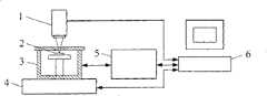
图1是微机电系统机械组元可靠性评估的测试装置组成示意图。Figure 1 is a schematic diagram of the composition of the testing device for the reliability evaluation of mechanical components of MEMS.
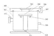
图2是环境腔室的正视剖面图。Figure 2 is a front cross-sectional view of the environmental chamber.
图3是环境腔室的顶视图。Figure 3 is a top view of the environmental chamber.
图4是环境实现与测量单元组成示意图。Fig. 4 is a schematic diagram of environment realization and measurement unit composition.
图5是电激励单元,电测量单元与环境腔室的连接示意图。Fig. 5 is a schematic diagram of the connection between the electrical excitation unit, the electrical measurement unit and the environmental chamber.
图6是微机电系统机械组元可靠性评估的测试方法流程图。Fig. 6 is a flow chart of a test method for reliability evaluation of MEMS mechanical components.
图7是依照本发明实施例一、采用本发明的测试装置对一个MEMS悬臂梁结构样品进行可靠性测试的系统配置示意图。FIG. 7 is a schematic diagram of a system configuration for performing a reliability test on a sample of a MEMS cantilever beam structure by using the test device of the present invention according to
具体实施方式Detailed ways
如图1所示,本发明提供的测试装置包括光学测量单元1、环境腔室3、环境控制与测量单元5以及数据采集和控制单元6。As shown in FIG. 1 , the test device provided by the present invention includes an
光学测量单元1采用基于自动聚焦光学测量技术的商业化位移传感器测量微机械系统机械组元2的轮廓曲线,从而获得被测微机电系统机械组元2在失效前后的三维形貌信息。The
如图2和图3所示,环境腔室3用于实现温度、气压、可控气氛、湿度等环境条件并进行微机电系统机械组元2的可靠性测试。环境腔室3通过固定支撑条310固定于XY工作台4上,可跟随XY工作台4在水平面内移动,通过水平调节螺丝311可实现环境腔室3的水平调节功能。通过优化环境腔室3的结构设计,保证环境腔室3的质量低于XY工作台4正常工作的载荷限制。环境腔室3包括腔体301、顶盖法兰302、光学窗口303、样品台304和加热单元305。其中光学窗口303采用双面镀膜的低折射率光学玻片,光学窗口303通过树脂胶粘接固定于顶盖法兰302上。腔体301、顶盖法兰302与光学窗口303构成密闭腔室,腔体301与顶盖法兰之间通过密封圈306实现真空密封。样品台304位于环境腔室3内光学窗口303正下方,用于放置被测微机电系统机械组元2。样品台304具有不同的固定方式以满足不同被测微机电系统机械组元2的测试需求。加热单元305采用商业化的加热器,位于样品台304的底面或上面,,可以采用直接加热和间接加热两种方式对被测微机电系统机械组元2进行加热。环境腔室3的腔体301包括抽气接口法兰312、真空测量接口法兰313、多个进气口309以及电极接口法兰308。As shown in FIG. 2 and FIG. 3 , the
环境控制与测量单元5用于实现环境腔室3内所需的各种环境条件并测量相应的条件。如图4所示,环境控制与测量单元5包括真空实现装置510、真空测量装置520、气氛实现装置530、湿度实现装置540和温湿度测量装置550。真空实现装置510通过抽气接口法兰312与环境腔室3连接,用于实现环境腔室3内的真空环境,包括低真空泵511、高真空泵512和波纹管514。优选的真空实现装置510包括减振质量块513,位于高真空泵512和环境腔室3的抽气接口法兰312之间,用于支撑和固定波纹管512,减小高真空泵512通过波纹管514向环境腔室3传递的机械振动,从而防止对XY工作台4的损害以及对光学测量的影响。真空测量装置520通过真空测量接口法兰313与环境腔室3连接,用于测量环境腔室3内的真空度,包括低真空规521、高真空规522和真空计523。低真空规521采用热偶真空规,用于环境腔室3内由常压到低真空水平的压力检测。高真空规522采用冷阴极真空规,用于环境腔室3内高真空水平的压力检测。气氛调节装置530通过进气口309与环境腔室3连接,用于实现环境腔室3内的不同气氛环境,包括气源531、质量流量控制器532和调节阀门533。通过气路并联和阀门控制的方式可以实现多种气氛的更换,一种气源531、一个质量流量控制器532和一个调节阀门组成一条气氛控制支路,气源的气体种类包括氮气、氦气、氧气等。湿度调节装置540,通过进气口309与环境腔室3连接,用于实现环境腔室3内的不同湿度环境,包括加湿装置541、湿气管道542和控制阀门543。温湿度测量装置550通过电极接口法兰308与环境腔室3连接,用于测量环境腔室3内的温度和湿度,该温湿度测量装置550是温湿度集成测量元件或者温度、湿度测量的分立元件。The environmental control and measurement unit 5 is used to realize various environmental conditions required in the
数据采集和控制单元6用于控制XY工作台4并带动环境腔室3在水平面内移动,控制环境控制与测量单元5实现与测量各种环境条件,控制激励单元7向被测微机电系统机械组元2产生激励信号,记录光学测量单元1或电学测量单元8的测量数据。如图5所示,电激励单元7和电学测量单元8分别通过电极接口法兰308与被测微机电系统机械组元2相连接,可向被测微机电系统机械组元2发送电激励信号及从被测微机电系统机械组元2接收电测量信号。The data acquisition and
图6示出了基于上述测试装置的微机电系统机械组元可靠性评估的测试方法流程图,具体步骤如下:Fig. 6 shows the flow chart of the test method for the reliability evaluation of MEMS mechanical components based on the above-mentioned test device, and the specific steps are as follows:
1)将被测微机电系统机械组元2置于环境腔室3的样品台304上;1) placing the measured MEMS
2)通过环境控制与测量单元5对环境腔室3进行真空、气压、气氛、温度和湿度的精确控制;2) Precisely control the vacuum, air pressure, atmosphere, temperature and humidity of the
3)通过数据采集和控制单元6控制激励单元7向被测微机电系统机械组元2产生激励信号,通过光学测量单元1或电学测量单元8监测被测微机电系统机械组元2是否发生失效,同时数据采集和控制单元6记录光学测量单元1或电学测量单元8的测量数据;3) The
4)取出被测微机电系统机械组元2,完成测试。4) Take out the MEMS
以下结合具体的实施例对本发明微机电系统机械组元可靠性评估的测试方法作进一步说明。The test method for reliability evaluation of MEMS mechanical components of the present invention will be further described in conjunction with specific examples below.
图7是采用本发明的测试装置和测试方法对MEMS悬臂梁结构进行疲劳失效的可靠性测试的示意图。Fig. 7 is a schematic diagram of a reliability test for fatigue failure of a MEMS cantilever beam structure using the test device and test method of the present invention.
悬臂梁结构是MEMS中最常见的机械组元之一,其器件应用包括力传感器、加速度传感器、MEMS开关、AFM等。疲劳断裂失效是悬臂梁结构常见的失效模式之一,即结构在循环载荷作用下,经历一定循环后发生断裂失效。获得悬臂梁结构材料的应力-寿命数据及疲劳强度数据,澄清疲劳失效产生和传播的机理以及起决定作用的环境因素,对于提高相关MEMS器件的可靠性至关重要。The cantilever beam structure is one of the most common mechanical components in MEMS, and its device applications include force sensors, acceleration sensors, MEMS switches, AFM, etc. Fatigue fracture failure is one of the common failure modes of cantilever beam structures, that is, the structure fails after a certain cycle under cyclic loading. Obtaining stress-life data and fatigue strength data of cantilever beam structural materials, clarifying the mechanism of fatigue failure generation and propagation and the decisive environmental factors are crucial to improving the reliability of related MEMS devices.
采用体硅微加工工艺制作悬臂梁结构。通过PZT压电片激励的方式进行悬臂梁结构的疲劳失效研究,被测悬臂梁结构703通过机械固定方式置于PZT压电片702上,PZT压电片702固定于样品台701上。PZT压电片702上的电极通过导线与电极接口法兰308上的电极连接。函数发生器输出方波电压信号并经功率放大器后产生PZT压电片702的工作驱动电压信号,通过电极接口法兰308输入到PZT压电片702的电极,从而驱动PZT压电片702振动并将振动传递给被测悬臂梁结构703。The cantilever beam structure is fabricated by bulk silicon micromachining technology. The fatigue failure research of the cantilever beam structure is carried out by means of PZT piezoelectric sheet excitation. The tested
为澄清疲劳失效产生和传播的机理以及起决定作用的环境因素,在环境腔室中进行不同环境条件下的悬臂梁结构的疲劳失效可靠性测试,包括:进行真空和空气中的测试以比较在同等循环载荷下悬臂梁结构的可靠性差异;进行从环境湿度(50%相对湿度)到高湿度(95%相对湿度)范围内的疲劳失效实验,研究在不同湿度下结构疲劳失效的差异,以分析水汽在疲劳裂纹产生及传播过程中的影响和作用;通过片上加热电阻加热执行悬臂梁结构在室温到200℃温度范围内的疲劳寿命实验,研究温度对悬臂梁结构疲劳失效的影响。In order to clarify the mechanism of fatigue failure generation and propagation and the decisive environmental factors, the fatigue failure reliability test of the cantilever beam structure under different environmental conditions was carried out in the environmental chamber, including: vacuum and air tests to compare Differences in the reliability of cantilever beam structures under the same cyclic load; carry out fatigue failure experiments ranging from ambient humidity (50% relative humidity) to high humidity (95% relative humidity), and study the difference in fatigue failure of the structure under different humidity, in order to Analyze the influence and effect of water vapor on the generation and propagation of fatigue cracks; conduct fatigue life experiments of cantilever beam structures in the temperature range from room temperature to 200°C by on-chip heating resistance heating, and study the influence of temperature on fatigue failure of cantilever beam structures.
当被测悬臂梁结构发生疲劳失效后,结合材料微观表征手段扫描电子显微镜和原子力显微镜观察结构疲劳失效后的断面形貌,分析疲劳初始微裂纹产生区域及其传播方向,从而为澄清悬臂梁结构的疲劳失效机理提供有力依据。When the fatigue failure of the tested cantilever beam structure occurs, combined with the material microscopic characterization means scanning electron microscope and atomic force microscope to observe the cross-sectional morphology of the structure after fatigue failure, and analyze the fatigue initial micro-crack generation area and its propagation direction, so as to clarify the cantilever beam structure Provide a strong basis for the fatigue failure mechanism.
以上所述的具体实施例,对本发明的目的、技术方案和有益效果进行了进一步详细说明,所应理解的是,以上所述仅为本发明的具体实施例而已,并不用于限制本发明,凡在本发明的精神和原则之内,所做的任何修改、等同替换、改进等,均应包含在本发明的保护范围之内。The specific embodiments described above have further described the purpose, technical solutions and beneficial effects of the present invention in detail. It should be understood that the above descriptions are only specific embodiments of the present invention and are not intended to limit the present invention. Any modifications, equivalent replacements, improvements, etc. made within the spirit and principles of the present invention shall be included within the protection scope of the present invention.
Claims (6)
Priority Applications (1)
| Application Number | Priority Date | Filing Date | Title |
|---|---|---|---|
| CN2009100785627ACN101813590B (en) | 2009-02-25 | 2009-02-25 | Testing device and method for reliability evaluation of mechanical component of micro-electromechanical system |
Applications Claiming Priority (1)
| Application Number | Priority Date | Filing Date | Title |
|---|---|---|---|
| CN2009100785627ACN101813590B (en) | 2009-02-25 | 2009-02-25 | Testing device and method for reliability evaluation of mechanical component of micro-electromechanical system |
Publications (2)
| Publication Number | Publication Date |
|---|---|
| CN101813590A CN101813590A (en) | 2010-08-25 |
| CN101813590Btrue CN101813590B (en) | 2011-11-30 |
Family
ID=42620905
Family Applications (1)
| Application Number | Title | Priority Date | Filing Date |
|---|---|---|---|
| CN2009100785627AExpired - Fee RelatedCN101813590B (en) | 2009-02-25 | 2009-02-25 | Testing device and method for reliability evaluation of mechanical component of micro-electromechanical system |
Country Status (1)
| Country | Link |
|---|---|
| CN (1) | CN101813590B (en) |
Families Citing this family (12)
| Publication number | Priority date | Publication date | Assignee | Title |
|---|---|---|---|---|
| CN102879729B (en)* | 2012-09-25 | 2014-09-24 | 江苏物联网研究发展中心 | Built-in self-test system aiming at micro-electro-mechanical integrated system |
| CN103389428B (en)* | 2013-07-31 | 2016-03-23 | 杭州士兰微电子股份有限公司 | Microelectromechanical processes monitoring structure and method for supervising |
| CN103868810A (en)* | 2014-02-27 | 2014-06-18 | 中国科学院物理研究所 | Loading fatigue property test system of micromechanical device |
| CN107643104A (en)* | 2017-10-30 | 2018-01-30 | 佛山科学技术学院 | A multifunctional testing device with high and low temperature and atmosphere environment control |
| CN109540029A (en)* | 2018-11-19 | 2019-03-29 | 大连理工大学 | A kind of the microjet field measurement apparatus and method of jet pipe servo valve |
| CN110361645A (en)* | 2019-06-26 | 2019-10-22 | 浙江工业大学 | A kind of micro-electron packaging device reliability online testing device |
| CN110595880A (en)* | 2019-08-16 | 2019-12-20 | 南京理工大学 | A mesoscale cantilever beam bending fatigue test device and test method |
| CN111089844A (en)* | 2019-12-27 | 2020-05-01 | 桂林电子科技大学 | Optical fiber probe for monitoring micro-electro-mechanical system |
| CN111189627A (en)* | 2020-01-20 | 2020-05-22 | 北京航空航天大学 | Failure mode diagnosis method for petrochemical device power equipment |
| CN111397660B (en)* | 2020-04-03 | 2022-03-15 | 天津大学 | Multifunctional photonic chip detection system |
| CN115565835B (en)* | 2022-09-15 | 2025-08-26 | 大连理工大学 | A scanning electron microscope sample protection device for air-sensitive samples and its use method |
| WO2024060658A1 (en)* | 2022-09-21 | 2024-03-28 | 纳克微束(北京)有限公司 | Multi-functional sample chamber system applicable to electron microscope, and simulation method |
Citations (4)
| Publication number | Priority date | Publication date | Assignee | Title |
|---|---|---|---|---|
| CN1666952A (en)* | 2005-03-29 | 2005-09-14 | 华中科技大学 | Dynamic test loading device for MEMS wafer or device |
| CN1696604A (en)* | 2005-06-16 | 2005-11-16 | 华中科技大学 | A Measuring Device for Dynamic Characteristics of MEMS with Environmental Loading Function |
| CN1710388A (en)* | 2004-06-17 | 2005-12-21 | 史铁林 | 3-D measuring apparatus for dynamic property and reliability of microelectromechanic system |
| CN101319957A (en)* | 2008-06-03 | 2008-12-10 | 东南大学 | MEMS Beam Vibration Fatigue Reliability Online Automatic Testing Method and System |
- 2009
- 2009-02-25CNCN2009100785627Apatent/CN101813590B/ennot_activeExpired - Fee Related
Patent Citations (4)
| Publication number | Priority date | Publication date | Assignee | Title |
|---|---|---|---|---|
| CN1710388A (en)* | 2004-06-17 | 2005-12-21 | 史铁林 | 3-D measuring apparatus for dynamic property and reliability of microelectromechanic system |
| CN1666952A (en)* | 2005-03-29 | 2005-09-14 | 华中科技大学 | Dynamic test loading device for MEMS wafer or device |
| CN1696604A (en)* | 2005-06-16 | 2005-11-16 | 华中科技大学 | A Measuring Device for Dynamic Characteristics of MEMS with Environmental Loading Function |
| CN101319957A (en)* | 2008-06-03 | 2008-12-10 | 东南大学 | MEMS Beam Vibration Fatigue Reliability Online Automatic Testing Method and System |
Also Published As
| Publication number | Publication date |
|---|---|
| CN101813590A (en) | 2010-08-25 |
Similar Documents
| Publication | Publication Date | Title |
|---|---|---|
| CN101813590B (en) | Testing device and method for reliability evaluation of mechanical component of micro-electromechanical system | |
| CN111855457B (en) | Traceable in-situ micro-nano indentation test instrument and method under variable temperature working condition | |
| CN104502202B (en) | Online material biaxial static-dynamic performance test platform under service temperature | |
| CN103471905B (en) | For single-axis bidirectional micro mechanics measurement mechanism and the measuring method of scanning microscopy environment | |
| CN107607409B (en) | Ultra-high temperature complex load biaxial stretching compression testing device | |
| CN102331370B (en) | In-situ high-frequency fatigue material mechanical test platform under scanning electron microscope based on stretching/compressing mode | |
| CN204255775U (en) | Material twin shaft static and dynamic performance on-line testing platform under service temperature | |
| CN106840359A (en) | A kind of two-beam interference calibrating installation for laser vibration measurer | |
| CN101520385A (en) | Method for testing mechanical property and reliability of thin film material of micro-electromechanical system (MEMS) and device thereof | |
| CN107063839A (en) | The mechanics parameter measuring method and device of multi-layer compound film structure | |
| CN210154961U (en) | High-temperature micro-nano indentation testing device with inert gas protection function | |
| CN102288501A (en) | Precise nanoindentation test device | |
| CN101561334A (en) | Method for calibrating three-dimensional micro-touch force sensor | |
| CN102353576A (en) | Small-size test device for mechanical and electrical coupling characteristics | |
| CN103293065A (en) | Outward bending testing device of microstructural mechanical property sheet | |
| CN105784515A (en) | Vacuum ultrasonic vibration fatigue experimental system | |
| Iannacci et al. | A novel MEMS-based piezoelectric multi-modal vibration energy harvester concept to power autonomous remote sensing nodes for Internet of Things (IoT) applications | |
| CN1666952A (en) | Dynamic test loading device for MEMS wafer or device | |
| CN102759481B (en) | Multi-cell mechanical simulation experiment platform | |
| CN202057559U (en) | In-situ micro-nanoscale indentation testing device based on double-displacement detection | |
| Tsuchiya et al. | Tensile and tensile-mode fatigue testing of microscale specimens in constant humidity environment | |
| CN206557007U (en) | A kind of new type power confined compression test device | |
| CN103048013B (en) | Automatic loading platform of micro-nano sensor under variable environment | |
| CN203287264U (en) | Micro-structure mechanical property piece external-bending testing device | |
| CN100501362C (en) | vacuum sensor |
Legal Events
| Date | Code | Title | Description |
|---|---|---|---|
| C06 | Publication | ||
| PB01 | Publication | ||
| SE01 | Entry into force of request for substantive examination | ||
| C14 | Grant of patent or utility model | ||
| GR01 | Patent grant | ||
| CF01 | Termination of patent right due to non-payment of annual fee | Granted publication date:20111130 Termination date:20150225 | |
| EXPY | Termination of patent right or utility model |