CN101809629B - Drive recorder and setting method for the same - Google Patents
Drive recorder and setting method for the sameDownload PDFInfo
- Publication number
- CN101809629B CN101809629BCN200880108959XACN200880108959ACN101809629BCN 101809629 BCN101809629 BCN 101809629BCN 200880108959X ACN200880108959X ACN 200880108959XACN 200880108959 ACN200880108959 ACN 200880108959ACN 101809629 BCN101809629 BCN 101809629B
- Authority
- CN
- China
- Prior art keywords
- acceleration
- vehicle
- value
- drive recorder
- mentioned
- Prior art date
- Legal status (The legal status is an assumption and is not a legal conclusion. Google has not performed a legal analysis and makes no representation as to the accuracy of the status listed.)
- Active
Links
Images


Classifications
- G—PHYSICS
- G07—CHECKING-DEVICES
- G07C—TIME OR ATTENDANCE REGISTERS; REGISTERING OR INDICATING THE WORKING OF MACHINES; GENERATING RANDOM NUMBERS; VOTING OR LOTTERY APPARATUS; ARRANGEMENTS, SYSTEMS OR APPARATUS FOR CHECKING NOT PROVIDED FOR ELSEWHERE
- G07C5/00—Registering or indicating the working of vehicles
- G07C5/08—Registering or indicating performance data other than driving, working, idle, or waiting time, with or without registering driving, working, idle or waiting time
- G07C5/0841—Registering performance data
- G07C5/0875—Registering performance data using magnetic data carriers
- G07C5/0891—Video recorder in combination with video camera
- G—PHYSICS
- G07—CHECKING-DEVICES
- G07C—TIME OR ATTENDANCE REGISTERS; REGISTERING OR INDICATING THE WORKING OF MACHINES; GENERATING RANDOM NUMBERS; VOTING OR LOTTERY APPARATUS; ARRANGEMENTS, SYSTEMS OR APPARATUS FOR CHECKING NOT PROVIDED FOR ELSEWHERE
- G07C5/00—Registering or indicating the working of vehicles
- G07C5/08—Registering or indicating performance data other than driving, working, idle, or waiting time, with or without registering driving, working, idle or waiting time
- G07C5/0841—Registering performance data
- G07C5/085—Registering performance data using electronic data carriers
- G07C5/0858—Registering performance data using electronic data carriers wherein the data carrier is removable
Landscapes
- Physics & Mathematics (AREA)
- General Physics & Mathematics (AREA)
- Engineering & Computer Science (AREA)
- Multimedia (AREA)
- Time Recorders, Dirve Recorders, Access Control (AREA)
- Traffic Control Systems (AREA)
Abstract
Translated fromChinese
Description
Translated fromChinese技术领域technical field
本发明涉及行车记录器和行车记录器的设定方法,尤其涉及通过加速度传感器检测加速度的行车记录器以及行车记录器的设定方法。The invention relates to a driving recorder and a setting method of the driving recorder, in particular to a driving recorder which detects acceleration through an acceleration sensor and a setting method of the driving recorder.
背景技术Background technique
以往,提出了通过设置在车辆上的照相机拍摄车辆周围的影像并在碰撞或急刹车等对车辆造成冲击时记录周围影像和车辆速度的车载用影像等记录装置,所谓的行车记录器。通过将行车记录器配备在车辆上,在发生事故时通过分析所记录的信息,可以查证事故原因。此外,能够在寻求提高驾驶者的安全驾驶意识的同时,使记录平日的驾驶状况的影像作为安全驾驶指导等进行利用。Conventionally, there has been proposed a so-called drive recorder, a vehicle-mounted video recorder that captures images around the vehicle with a camera installed on the vehicle and records the surrounding images and vehicle speed when the vehicle is impacted by a collision or sudden braking. By installing a driving recorder on the vehicle, the cause of the accident can be verified by analyzing the recorded information in the event of an accident. In addition, it is possible to use images recording daily driving conditions as safe driving guidance and the like while seeking to improve the driver's awareness of safe driving.
专利文件1和2公开了循环存储通过车载照相机拍摄的影像并将事故发生时存储的影像记录在其它记录媒体上的行车记录器。此外,专利文件3和4公开了循环存储车辆速度或变速器的换档位置等行驶数据并将事故发生时存储的行驶数据记录在其它记录媒体上的行车记录器。
专利文件1:特开昭63-16785号公报Patent Document 1: JP-A-63-16785 Gazette
专利文件2:特开平06-237463号公报Patent Document 2: JP-06-237463 Gazette
专利文件3:特开平06-331391号公报Patent Document 3: JP-06-331391 Gazette
专利文件4:特开平06-186061号公报Patent Document 4: JP-06-186061 Gazette
转弯,特别是急转弯行驶时,即使采用正常的方向盘操作,也存在车辆的左右方向上大的加速度起作用,被误检测为车辆受到大的加速度的情况。由于误检测,当影像信息被记录在存储卡中时,存在大多记录不必要的影像信息而不能有效地利用容量有限的存储卡的问题。When turning, especially when driving in a sharp turn, even with normal steering wheel operation, there are cases where a large acceleration in the left and right directions of the vehicle acts, and it may be falsely detected as the vehicle receiving a large acceleration. Due to misdetection, when video information is recorded in the memory card, there is a problem that unnecessary video information is often recorded and the memory card with a limited capacity cannot be effectively used.
发明内容Contents of the invention
因此,本发明的目的在于提供一种行车记录器,即使在转弯行驶中,只要进行正常的方向盘操作,也能够进行不被误检测为车辆受到大的加速度的加速度检测。Therefore, an object of the present invention is to provide a drive recorder capable of detecting acceleration without erroneously detecting that the vehicle has received a large acceleration as long as the steering wheel is operated normally even when the vehicle is turning.
此外,考虑从在车辆的左右方向上检测的加速度中减去预定修正值,即使在转弯行驶中,只要进行正常的方向盘操作,也不被误检测为车辆受到大的加速度。为此,有必要将行车记录器的加速度传感器相对车辆对准指定方向进行设定。In addition, considering subtracting a predetermined correction value from the acceleration detected in the left and right directions of the vehicle, it is not erroneously detected that the vehicle has received a large acceleration even when turning, as long as the steering wheel is operated normally. For this reason, it is necessary to set the acceleration sensor of the driving recorder in a specified direction relative to the vehicle.
然而,如果固定行车记录器的安装方向,则发生不符合安装的车种或用户的要求的情况,如果自由设定行车记录器的安装方向,则很难正确地判断加速度传感器具有的多个轴的哪个轴与车辆的哪个方向一致。However, if the installation direction of the driving recorder is fixed, it may not meet the requirements of the installed vehicle type or the user. If the installation direction of the driving recorder is freely set, it is difficult to correctly judge the multiple axes of the acceleration sensor. Which axis of the vehicle corresponds to which direction of the vehicle.
因此,本发明的目的在于提供一种能够提高安装时的自由度的行车记录器的设定方法。Therefore, it is an object of the present invention to provide a method of setting a drive recorder capable of increasing the degree of freedom at the time of installation.
本发明所述的行车记录器,其特征在于,具有:加速度传感器,其检测车辆的行进方向的第1加速度和车辆的左右方向的第2加速度;以及控制部,其基于第1加速度以及从第2加速度的绝对值中减去修正值的值求出合成加速度,并在合成加速度超过阈值时,向记录元件记录从摄影部接收的影像信息。The drive recorder according to the present invention is characterized in that it has: an acceleration sensor that detects a first acceleration in the traveling direction of the vehicle and a second acceleration in the left-right direction of the vehicle; 2. Composite acceleration is obtained by subtracting the correction value from the absolute value of the acceleration, and when the composite acceleration exceeds a threshold value, the video information received from the imaging unit is recorded in the recording device.
如果采用本发明所述的行车记录器,则在转弯行驶中,由于从在车辆的左右方向上检测的加速度的绝对值中减去修正值,因此,只要进行正常的方向盘操作,即使在转弯行驶中,也不存在被误检测为车辆受到大的加速度。If the drive recorder of the present invention is adopted, then in turning travel, since the correction value is subtracted from the absolute value of the acceleration detected in the left and right directions of the vehicle, as long as the normal steering wheel operation is carried out, even when turning travel In , there is no false detection that the vehicle is subjected to a large acceleration.
在本发明所述的行车记录器的设定方法中,其特征在于,具有检测车辆的第1方向的第1加速度和车辆的第2方向的第2加速度的加速度传感器;判断车辆是否停止;在车辆停止后,检测车辆起动时的上述第1加速度和上述第2加速度;基于第1加速度和第2加速度判断车辆的左右方向的加速度和车辆的前后方向的加速度。In the setting method of the driving recorder according to the present invention, it is characterized in that, there is an acceleration sensor that detects the first acceleration in the first direction of the vehicle and the second acceleration in the second direction of the vehicle; it is judged whether the vehicle is stopped; After the vehicle stops, the above-mentioned first acceleration and the above-mentioned second acceleration are detected when the vehicle starts; the acceleration in the left-right direction of the vehicle and the acceleration in the front-rear direction of the vehicle are determined based on the first acceleration and the second acceleration.
如果采用本发明所述的行车记录器的设定,则无需从行车记录器的外部获取信号,就能够判断加速度传感器的输出是否是车辆的左右方向的加速度和车辆的前后方向的加速度的任意之一,因此,能够提高行车记录器安装时的自由度。If the setting of the drive recorder according to the present invention is adopted, it is not necessary to acquire signals from the outside of the drive recorder, and it can be judged whether the output of the acceleration sensor is any one of the acceleration in the left-right direction of the vehicle and the acceleration in the front-rear direction of the vehicle. One, therefore, the degree of freedom in the installation of the drive recorder can be improved.
此外,如果采用本发明所述的行车记录器的设定,则在转弯行驶中,由于从在车辆的左右方向上检测的加速度的绝对值中减去修正值,因此,只要进行正常的方向盘操作,即使是在转弯行驶中,也可以防止误检测为车辆受到大的加速度。In addition, if the setting of the driving recorder according to the present invention is adopted, during turning, since the correction value is subtracted from the absolute value of the acceleration detected in the left and right directions of the vehicle, as long as the normal steering wheel operation is performed, , Even when turning, it is possible to prevent false detection that the vehicle is subjected to a large acceleration.
附图说明Description of drawings
图1是示出将行车记录器搭载在车辆上的例子的图。FIG. 1 is a diagram showing an example in which a drive recorder is mounted on a vehicle.
图2是示出将行车记录器等设置在车辆上的例子的图。FIG. 2 is a diagram showing an example in which a drive recorder and the like are installed on a vehicle.
图3是行车记录器主体的斜视图。Fig. 3 is a perspective view of the main body of the driving recorder.
图4是示出再现装置的外观例子的图。FIG. 4 is a diagram showing an example of the appearance of a playback device.
图5是示出行车记录器的电结构的方框图。FIG. 5 is a block diagram showing an electrical configuration of the drive recorder.
图6是示出电源控制电路的电结构的方框图。FIG. 6 is a block diagram showing an electrical configuration of a power supply control circuit.
图7是示出再现装置的电结构的方框图。Fig. 7 is a block diagram showing the electrical configuration of the playback device.
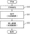
图8是示出行车记录器的处理流程的一个例子的图。FIG. 8 is a diagram showing an example of a processing flow of the drive recorder.
图9是示出加速度传感器的自我诊断处理流程的图。FIG. 9 is a diagram showing a flow of self-diagnosis processing of the acceleration sensor.
图10(a)是示出将行车记录器2垂直配置在车辆1上的情形的图,图10(b)是示出将行车记录器2水平配置在车辆1上的情形的图,图10(c)是示出从图10(b)的状态进一步将行车记录器2倾斜仅仅θ度的状态的图。FIG. 10( a) is a diagram showing a situation where the
图11是示出G值检测处理流程的图。FIG. 11 is a diagram showing the flow of G value detection processing.
图12是示出用于进行加速度传感器5的输出的确认处理的流程的图。FIG. 12 is a diagram showing a flow of processing for checking the output of the acceleration sensor 5 .
图13是示出G检测的处理流程的图。FIG. 13 is a diagram showing a processing flow of G detection.
图14(a)是示出通过图11的处理流程求出的G值50的曲线图示例(1)的图,图14(b)是示出在第2RAM 15中循环记录的影像信息和在存储卡6中记录的影像信息的图。Fig. 14(a) is a diagram showing a graph example (1) of the
图15(a)是示出通过图11的处理流程求出的G值60的曲线图示例(2)的图,图15(b)是示出在第2RAM 15中循环记录的影像信息和在存储卡6中记录的影像信息的图。Fig. 15 (a) is a diagram showing an example (2) of the graph of the
图16(a)是示出通过图11的处理流程求出的G值70的曲线图示例(3)的图,图16(b)是示出在第2RAM 15中循环记录的影像信息和在存储卡6中记录的影像信息的图。Fig. 16(a) is a diagram showing an example (3) of the graph of the
图17(a)是示出通过图11的处理流程求出的G值80的曲线图示例(4)的图,图17(b)是示出在第2RAM 15中循环记录的影像信息和在存储卡6中记录的影像信息的图。Fig. 17(a) is a diagram showing an example (4) of the graph of the
图18是示出减电压处理流程(1)的图。FIG. 18 is a diagram showing a voltage reduction processing flow (1).
图19是示出减电压处理流程(2)的图。FIG. 19 is a diagram showing a voltage reduction processing flow (2).
图20是示出电压下降状态的图。FIG. 20 is a diagram showing a voltage drop state.
图21是示出模式切换流程的图。FIG. 21 is a diagram showing a flow of mode switching.
图22是示出再现顺序的图。FIG. 22 is a diagram showing the playback sequence.
图23是示出存储卡的使用例的流程的图。FIG. 23 is a diagram showing a flow of a usage example of a memory card.
图24是示出视野范围的对应表的图。FIG. 24 is a diagram showing a correspondence table of field of view ranges.
图25是示出用于显示影像信息的画面例子的显示图。FIG. 25 is a display diagram showing an example of a screen for displaying video information.
图26是示出驾驶状况分类处理流程的图。FIG. 26 is a diagram showing a flow of driving situation classification processing.
图27是示出样本线的图。Fig. 27 is a diagram showing sample lines.
图28是示出峰值主文件的一个例子的图。Fig. 28 is a diagram showing an example of a peak master file.
图29是示出编辑画面的一个例子的图。FIG. 29 is a diagram showing an example of an editing screen.
图30(a)是示出G2值的样本线300的图,图30(b)是示出G1值的样本线301的图,图30(c)是示出车速的样本线302的图。30( a ) is a graph showing a
图31(a)是示出G2值的样本线310的图,图31(b)是示出G1值的样本线311的图,图31(c)是示出车速的样本线312的图。31( a ) is a graph showing a
图32(a)是示出G2值的样本线320的图,图32(b)是示出G1值的样本线321的图,图32(c)是示出车速的样本线322的图。32( a ) is a graph showing a sample line 320 of G2 values, FIG. 32( b ) is a graph showing a
图33(a)是示出G2值的样本线330的图,图33(b)是示出G1值的样本线331的图,图33(c)是示出车速的样本线332的图。33( a ) is a graph showing a
图34(a)是示出G2值的样本线340的图,图34(b)是示出G1值的样本线341的图,图34(c)是示出车速的样本线342的图。34( a ) is a graph showing a
具体实施方式Detailed ways
以下参照附图,详细说明本发明的实施方式。另外,本发明的技术范围并不局限于这些实施方式,而是涉及权利要求书所记载的发明及其等同物。此外,在不脱离本发明宗旨的前提下,能够在添加了各种变更的形态下实施。Embodiments of the present invention will be described in detail below with reference to the drawings. In addition, the technical scope of the present invention is not limited to these embodiments, but relates to the inventions described in the claims and their equivalents. In addition, it can implement in the form which added various changes, without deviating from the summary of this invention.
首先说明行车记录器中信息的记录。First, the recording of information in the driving recorder will be described.
图1是示出在车辆1上搭载行车记录器2的图。FIG. 1 is a diagram showing a
在车辆1内设置有行车记录器2,其与拍摄车辆1的前方的第1照相机3和拍摄车辆1的后方的第2照相机4连接。将第1照相机3和第2照相机4拍摄的影像信息循环存储在行车记录器2内的半导体存储部15中。如果指定的记录条件成立,则存储在半导体存储部15中的影像信息被记录在存储卡6中。所谓指定的记录条件是指由于事故等的发生而对车辆1造成冲击的情形,其详细内容在后面描述。A
此外,行车记录器2除了影像信息之外,获得包括车辆的速度信息等的运行信息,并循环存储在行车记录器2内的半导体存储部15中。运行信息在前述的记录条件成立时与影像信息相关联地连同影像信息一起被记录在存储卡6中。关于运行信息的详细情形在后面描述。In addition, the
图2是示出将行车记录器2设置在车辆1中的例子的图。FIG. 2 is a diagram showing an example in which the
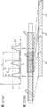
行车记录器2被固定在例如方向盘的左下方中央面板的一端等,并与第1照相机3(以及图2中未示出的第2照相机4)、GPS传感器9、未图示的车速传感器10、未图示的电池21、车载用的显示部30等电连接。第1照相机3安装在车室内镜子的后侧的前挡风玻璃面上,拍摄车辆前方,并将影像信息向行车记录器2发送。The driving
图3是行车记录器2的主体的斜视图。FIG. 3 is a perspective view of the main body of the
在行车记录器2中具有:麦克风7、摄影开关8、电源开关20、LED 25、蜂鸣器26、未图示的开闭传感器27、开闭旋钮31等。The driving
麦克风7搜集车辆1内的声音。摄影开关8确定在行车记录器2中记录影像信息的定时,并使用在用于行车记录器2的初始化等的各输入上。LED 25和蜂鸣器26具有通过发生发光和告警音而向用户通知行车记录器2的状况的功能。The
开闭旋钮31在存储卡6插入构成后述的I/F 11的插槽之后,滑动到其上方定位以保护存储卡6(图3的状况)。当拔出存储卡6时,使开闭旋钮31向箭头A的方向滑动。此外,行车记录器2被构成为具有与开闭旋钮31连动的开闭传感器27,并在开闭旋钮31在存储卡6的上部滑动的状态下(图3的状态)输出表示闭状态的OFF信号,在拔出存储卡6的状态下输出表示开状态的ON信号。After the
图4是示出再现装置的外观例子的图。FIG. 4 is a diagram showing an example of the appearance of a playback device.
在存储卡6中记录的影像信息以及运行信息等通过包括个人计算机等的再现装置400再现。存储卡6被插入与个人计算机连接的I/F中,影像信息和运行信息等被读取。用户通过查证再现的影像信息以及运行信息等进行车辆的行驶状态或事故原因的分析等。Video information, operation information, and the like recorded on the
图5是示出行车记录器2的电结构的方框图。FIG. 5 is a block diagram showing the electrical configuration of the
第1照相机3拍摄车辆1的前方,并受到控制以将模拟的视频信号作为第1影像信息500输出,由例如作为二元图像传感器的CCD图像传感器(电荷耦合器件图像传感器)或CMOS图像传感器(互补金属氧化物半导体图像传感器)构成。The
第2照相机4作为第2台照相机设置在车辆1内,拍摄车辆后方和车室内等与第1照相机3不同的方向,并受到控制以将模拟视频信号作为第2影像信息501输出。另外,在只需要一台照相机时,不必将第2照相机4与行车记录器2连接。The
加速度传感器5由检测对车辆1造成的冲击的大小作为重力加速度的所谓G传感器(重力加速度传感器)构成。加速度传感器5由受到冲击时基于其重力加速度产生电流的半导体构成,检测车辆的前后方向以及左右方向的重力加速度的大小,并向CPU 24输出重力加速度信息502。The acceleration sensor 5 is composed of a so-called G sensor (gravitational acceleration sensor) that detects the magnitude of the impact on the
存储卡6是能够从行车记录器2中取出的记录媒体,由作为可编程非易失性半导体存储卡的SD卡(安全数码存储卡)构成。在存储卡6中记录有影像信息和运行信息。此外,在存储卡6中分别记录有后述的记录条件、存储卡6的固有ID、使用存储卡6的使用者(例如,出租车乘务员等)的ID或姓名的数据等各种信息。进一步地,在存储卡6中设置有双列直插式(DIP)开关,通过DIP开关的操作能够将存储卡6设成写入禁止状态。The
另外,在本实施方式中,虽然使用SD卡作为可取出的存储媒体,但并不仅仅局限于此,也可以使用其它可取出的存储卡(例如,CF卡(紧凑式闪存卡)或者存储棒)、硬盘等。此外,也可以代替存储卡6而在行车记录器2中内置硬盘,在这种情况下,也可以采用在行车记录器2中设置发送电路并通过无线通信将记录在硬盘中的影像信息和运行信息发送给再现装置400的结构。In addition, in this embodiment, although an SD card is used as a removable storage medium, it is not limited to this, and other removable storage cards (for example, CF cards (compact flash cards) or memory sticks) can also be used. ), hard disk, etc. In addition, it is also possible to replace the
麦克风7与CPU 24电连接,搜集车辆1的车室内或车外的声音,并作为声音信息503向CPU 24发送。声音信息503用CPU 24内的模拟/数字转换器转换为数字信号。另外,优选地,使用麦克风的正面灵敏度高的单一指向性麦克风,以便无需搜集道路上的噪音。
摄影开关(摄影SW)8通过用户的操作向与其电连接的CPU 24发送信号。这样,CPU 24进行控制以使在第2RAM 15中存储的影像信息以及运行信息记录在存储卡6中。即,摄影SW 8的操作作为记录条件的成立起作用。另外,也可以仅仅将摄影SW 8操作的瞬间的影像信息记录在存储卡6中。此外,摄影SW 8,如后面所述,也可以用作用于使用行车记录器2的其它功能的操作装置。The camera switch (photograph SW) 8 sends a signal to the
GPS(全球定位系统)接收机9从多个GPS卫星接收包含卫星的轨道和来自搭载在卫星上的原子时钟的时刻数据的电波信号,并通过所接收的电波的时间差计算与各个卫星的相对距离差,得到当前位置信息。如果捕捉3个卫星的电波,则可以判断地球上的平面位置。GPS接收机9在检测出当前位置信息时,将包括位置信息和时刻信息的GPS信息504向CPU 24发送。The GPS (Global Positioning System)
车速传感器10用磁传感器或光传感器构成,并将在车辆1的车轮轴上设置的电机的旋转作为旋转脉冲信号505输出。另外,CPU 24通过根据从车速传感器10接收的脉冲信号计算每单位时间的车轮旋转次数,计算车辆1的速度信息。The vehicle speed sensor 10 is constituted by a magnetic sensor or an optical sensor, and outputs the rotation of a motor provided on the wheel shaft of the
接口(I/F)11也构成在行车记录器2上设置的存储卡6的插入口,所谓的插槽部。I/F 11将从行车记录器2发送的包括影像信息和运行信息的记录信息506向所插入的存储卡6传送,并将在行车记录器2中预先存储的各信息507向CPU 24传送。The interface (I/F) 11 also constitutes an insertion port of the
视频开关(以下表示为视频SW)12是用于在设置有多个照相机时切换进行拍摄的照相机的开关。在本实施方式中,构成为与第1照相机3和第2照相机4相连,并根据来自CPU 24的选择信号508选择一方的照相机。将来自所选择的照相机的影像信息作为选择影像信息509向图像处理电路13输出。另外,也可以构成为使视频SW12具有计时功能,并以一定的时间间隔进行切换。A video switch (hereinafter referred to as video SW) 12 is a switch for switching a camera for shooting when a plurality of cameras are installed. In the present embodiment, the
图像处理电路13将从第1照相机3和第2照相机4经由视频SW12输入的选择影像信息509转换成数字信号,并制成图像数据510输出。图像处理电路13由JPEG-IC(联合图像专家组-集成电路)构成,并制作JPEG形式的数据。在这种情况下,JPEG-IC由于不具有指定地址输出数据的功能,因此向第1RAM(随机存取存储器)14写入每秒30个文件,并对每一个文件进行写入处理。The
第1RAM 14暂时存储由图像处理电路13转换的图像数据510。另外,第1RAM 14与CPU 24内的DMA(直接存储器存取)电路连接,所输入的影像中每3张中1张,即每秒10个文件通过DMA的功能向第2RAM 15传送,并被循环存储。The
第2RAM(半导体存储部)15循环地存储通过图像处理回路13转换成图像数据的影像信息以及运行信息。The second RAM (semiconductor storage unit) 15 cyclically stores image information and operation information converted into image data by the
另外,在第1RAM 14和第2RAM 15中使用例如SDRAM(同步动态随机存取存储器)。SDRAM由于被设计成与CPU的时钟同步动作,因此,输入输出的等待时间短,与以往的DRAM(动态随机存取存储器)相比,能够高速地进行存取,适合于进行高速处理大容量的影像信息的控制。In addition, SDRAM (Synchronous Dynamic Random Access Memory), for example, is used in the
非易失性ROM 16存储用于统一控制构成行车记录器2的硬件资源的控制程序17等。在非易失性ROM 16中,虽然可以使用掩模ROM,但如果使用作为可编程非易失性半导体存储器的闪速存储器、EEPROM(电可擦写可编程只读存储器)、强电介质存储器等,则能够进行程序的写入或消除。The
控制程序17被存储器在非易失性ROM 16内,并在行车记录器2启动时被CPU 24读出,作为各部件的控制和数据运算处理的程序起作用。The control program 17 is stored in the
附件开关(ACC开关)19与车辆1所具备的引擎启动用的锁芯电一体地构成。当通过用户的钥匙操作开关变成开时,向行车记录器2的CPU24和电源控制电路22发送附件开信号511。行车记录器2通过接收ACC开关19的附件开信号511,从电源控制电路22得到电源供给,并开始控制。另外,代替ACC开关19的输出信号,也可以利用点火钥匙输出信号(IG开信号)。The accessory switch (ACC switch) 19 is electrically integrally formed with the key cylinder for starting the engine included in the
电源开关(电源SW)20在由用户进行开关操作时,将电源开信号向行车记录器2的CPU 24和电源控制电路22发送。可以在不使ACC开关17开而使行车记录器2工作的情况下使用。The power switch (power supply SW) 20 sends a power-on signal to the
电池21配备在车辆1内,向行车记录器2提供电源。此外,电池向电源控制电路22提供电源。另外,电池21在能够装备在车辆上的情况下,只要能产生12伏的电动势即可。The
电源控制电路22向CPU 24以及行车记录器2的各部件提供来自电池21的电源。电源控制电路22将在后面详细描述。The power
CPU(中央处理单元)24作为行车记录器2的控制装置工作,由微型计算机等构成。CPU 24基于控制程序17,执行行车记录器2的各部件的控制和数据运算处理等。A CPU (Central Processing Unit) 24 operates as a control device of the
LED 25在由于从CPU 24提供电源而启动行车记录器2中点亮,并向用户报告正在启动中。此外,当在行车记录器2中发生异常时,LED 25被构成为通过CPU 24进行指定的熄灭,向用户报告异常的发生。
蜂鸣器26被构成为当在行车记录器中发生异常等时,通过CPU 24产生指定的告警音,向用户报告异常的发生。The
开闭传感器27被构成为根据伴随存储卡6的插拔的开闭旋钮31的移动,输出开信号和闭信号。The open/close sensor 27 is configured to output an open signal and a close signal in response to the movement of the open/
RTC(实时时钟)28产生与当前时刻对应的信号,并向CPU 24发送。The RTC (real time clock) 28 generates a signal corresponding to the current time, and sends it to the
显示部30由液晶显示器等构成,并在后述的指定状况下再现存储卡6中记录的影像信息。在图2中,虽然示出了将在车辆上搭载的导航装置的显示器作为显示部30使用的情况,但也可以利用其它的显示器作为显示部。通过使用显示部30,能够在事故发生时当场查证事故原因。总之,优选地,行车记录器2具有用于输出影像信息的输出端口。The
另外,行车记录器2也可以作为影像记录专用装置与第1照相机3、第2照相机4、GPS接收机9和/或显示部30容纳在同一框体内一体地构成。此外,行车记录器2也可以作为车载用导航装置的一个功能而构成。In addition, the
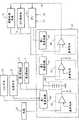
图6是示出电源控制电路22的电结构的方框图。FIG. 6 is a block diagram showing the electrical configuration of the power
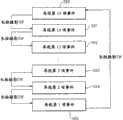
电源控制电路22包括:第1电源电路40、第2电源电路41、第3电源电路42、第1检测部43、第2检测部44、第3检测部45以及备用电池46等。The
第1电源电路40作为通过ACC开关19或电源开关20打开开始工作,并从额定12.0伏的电池21接受电力的供给,进行6.0伏的输出的定电压电源起作用。来自第1电源电路40的输出向第1照相机3以及第2照相机4提供。The first
第2电源电路41作为从额定6.0伏的第1电源电路40接受电力的供给并进行3.3伏的输出的定电压电源起作用。来自第2电源电路41的输出向构成图像处理电路13的JPEG电路、GPS接收机9、CPU 24等提供。The second
第3电源电路42作为从额定3.3伏的第2电源电路41接受电力的供给并进行1.8伏的输出的定电压电源起作用。来自第3电源电路41的输出向CPU 24等提供。The third
第1检测部43检测电池21的输出电压,并在来自电池21的输出电压降到8.0伏以下时向CPU 24输出第1减电压信号S1。此外,第2检测部44检测第1电源电路40的输出电压,并在来自第1电源电路40的输出电压降到3.7伏以下时向CPU 24输出第2减电压信号S2。进一步地,第3检测部45检测第2电源电路41的输出电压,并在第2电源电路41的输出电压降到3.0伏以下时,向构成图像处理电路13的JPEG电路、GPS接收机9、CPU 24输出重置信号S3,进行各部件的重置,以便防止由于低电压而引起的误动作。The
备用电池46由2个电容器构成,并被构成为即使在电池21的输出电压下降时也能够提供至少驱动构成图像处理电路13的JPEG电路、GPS接收机9以及CPU 24的电力指定的时间。如果由于碰撞事故等对车辆造成冲击,则恐怕发生电池21的破损或电池21和电源控制电路22之间的连接线的断线。备用电池46通过将蓄存的电源向CPU 24等提供,即使在这种情况下,也能够尽量保存处理中的影像信息等。对于减电压处理将在后面描述。The
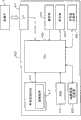
图7是示出再现装置400的电结构的方框图。FIG. 7 is a block diagram showing the electrical configuration of the
接口(I/F)411构成在再现装置400上设置的存储卡6的插入口,所谓的插槽部。I/F 411将在存储卡6中记录的影像信息以及运行信息传送到再现装置400一侧。The interface (I/F) 411 constitutes an insertion port for the
RAM 414用于在CPU 424进行从存储卡6传送的影像信息的图像处理和行驶信息的信息处理等时,暂时存储数据。在RAM 414中使用例如SDRAM。The
非易失性ROM 416存储用于统一控制构成再现装置400的硬件资源的控制程序417等。在非易失性ROM 16中,使用例如EEPROM、强电介质存储器等。The nonvolatile ROM 416 stores a
控制程序417被存储在非易失性ROM 416内,在再现装置400启动时被CPU 424读出,作为各部件的控制和数据运算处理的程序起作用。The
CPU 424作为再现装置400的控制装置而工作,由微型计算机等构成。CPU 424基于控制程序417,执行再现装置400的各部件的控制和数据运算处理等。The
操作部430由键盘、鼠标等构成,并作为在用户操作再现装置400时进行向CPU 424的操作输入的装置使用。The
显示部440由液晶显示装置等构成,并用于适当地显示在存储卡6中记录的影像信息以及运行信息。The
地图信息记录部450由硬盘、DVD等记录媒体构成,记录包括道路信息和限速信息等的地图信息。The map
卡信息记录部460由硬盘等记录媒体构成,并用作记录在存储卡6中记录的影像信息以及运行信息。The card
图8是示出行车记录器2的整个处理流程的图。FIG. 8 is a diagram showing the overall processing flow of the
图8所示的处理流程,主要是行车记录器2的CPU 24根据控制程序17与行车记录器2的各个构成元件共同地执行。The processing flow shown in Fig. 8 mainly is that the
当由于ACC开关19的开以及电源开关20的开而造成电源被加上、行车记录器2工作开始被指示时,CPU 24进行起动处理(S1)。在起动处理中,包括由引导程序引起的初始化处理以及与同行车记录器2相关的各种部件有关的自我诊断处理。关于自我诊断处理将在后面描述。When the power supply is turned on due to the opening of the
当行车记录器2的起动处理完成时,CPU 24循环地在第2RAM 15中存储影像信息(S2)。具体地,CPU 24以每秒钟10张的比率交替地获得由第1照相机3和第2照相机4拍摄的静止图像数据(640×480像素)(即,交替地每0.2秒获得来自照相机3的静止图像,每0.2秒获得来自照相机4的静止图像),并经由第1RAM 14循环地记录在第2RAM 15中。此外,CPU 24每当获得第1照相机3和第2状相机4的静止图像时,就获得运行信息,并与静止图像数据对应地循环记录在第2RAM 15中。另外,上述的CPU 24获得的静止图像数据的时间间隔和张数是一个例子,并不限定于此。When the activation process of the
接着,CPU 24进行后述的记录条件是否成立的判断(S3)。所谓记录条件成立的情况是指以下3种情况。另外,也可以将记录条件设为其中1种或2种,也可以将除此3种以外的其它条件定为记录条件。Next, the
1.G检测:是指加速度传感器检测到0.40G以上的重力加速度的情况。将这种情况作为记录条件的成立是因为在车辆1承受这样的重力加速度时,能够认识到事故的发生或事故迫在眉睫。另外,上述的设定值(0.40G)是一个例子,也可以采用其它数位。详细情况在后面描述。1. G detection: refers to the situation where the acceleration sensor detects the acceleration of gravity above 0.40G. The fact that this is the recording condition is established because when the
2.速度触发:是指从车速传感器10中检测的车辆1的指定期间内的速度差在阈值以上的情况。具体地,当在以60km/h以上行驶中1秒间的减速达到14km/h以上时,判断为记录条件成立。将这种情况作为记录条件的成立是因为当车辆1发生这样的速度变化时,能够认识到事故的发生或事故迫在眉睫。另外,上述的设定值(在以60km/h以上行驶中1秒间的减速达到14km/h以上)是一个例子,也可以采用其它数位。2. Speed trigger: refers to a situation where the speed difference of the
3.摄影SW:是指摄影SW 8被操作的情况。3. Camera SW: refers to the situation where the camera SW 8 is operated.
其次,CPU 24在记录条件成立时,将记录条件成立前12秒间以及成立后8秒间的合计20秒间的影像信息(每当记录条件成立一次时,200张静止图像)和运行信息从第2RAM 15传送到存储卡6中记录(S4)。此外,当记录条件成立时,将表示所成立的记录条件的事件数据(表示上述3个之内的任何一个的数据)合并记录在存储卡6中。在存储卡6中具有能够记录至少15个事件量的影像信息等的容量。Next, when the recording condition is established, the
另外,当记录条件成立时,也可以构成为将记录条件成立前12秒以及成立后8秒间的合计20秒间的从麦克风7获得的声音信息与影像信息一起进一步记录在存储卡6中。在存储卡6中记录的影像信息和运行信息等可以在再现装置400中显示,因此,行车记录器2的用户可以查证车辆1的行驶状态以及事故状况。另外,上述的CPU 24在记录条件成立时在存储卡6中记录的期间(记录条件成立前12秒以及成立后8秒)是一个例子,并不局限于此。Also, when the recording condition is satisfied, audio information obtained from the
所谓运行信息是指以下的信息。The operation information refers to the following information.
1.在加速度传感器5的各轴上检测的重力加速度信息(G1,G2)。1. Gravitational acceleration information ( G1 , G2 ) detected on each axis of the acceleration sensor 5 .
2.从GPS接收机9中检测的车辆1的位置信息以及时刻信息。2. The position information and time information of the
3.从车速传感器10中检测的速度信息。3. Speed information detected from the vehicle speed sensor 10 .
4.ACC开关19的ON/OFF信息。4. ON/OFF information of the
另外,运行信息的内容也不必局限于上述的信息,也可以包含例如闪光灯等灯光类的点亮状态或方向盘掌舵角这样的与车辆1的运行或行驶有关的信息。In addition, the content of the operation information is not necessarily limited to the above-mentioned information, and may include information related to the operation or running of the
接着,中央处理器24进行是否接收由于ACC开关19的OFF信号或电源开关20的OFF信号引起的结束信号(S5),当接收了结束信号时,进行结束处理(S6),结束一连串的处理。当没有接收到结束信号时,重复执行S2~S4。Then,
对行车记录器2的自我诊断处理进行说明。The self-diagnosis process of the
行车记录器2的自我诊断处理在图8所示的处理流程中的起动处理(S1)中进行,成为对象的是加速度传感器5、构成图像处理电路13的JPEG-IC、RTC 28以及第1照相机3和第2照相机4的连接状态。进行行车记录器2的自我诊断是因为在行车记录器2中记录的数据有成为关于查证事故等的证据资料的可能性。为此,要事前确认没有在行车记录器2中存在问题而不能正确记录数据的情况或在所记录的数据中发生问题的情况。The self-diagnosis process of the
图9是示出加速度传感器5的自我诊断处理流程的图。FIG. 9 is a diagram showing a self-diagnosis process flow of the acceleration sensor 5 .
首先,在加速度传感器5的3个轴(x轴、y轴和z轴)之中,CPU 24分别获得预先设定的与车辆1的前后方向平行的第1轴的输出G1以及预先设定的与车辆1的左右方向平行的第2轴的输出G2的输出(S11)。First, among the three axes (x-axis, y-axis and z-axis) of the acceleration sensor 5, the
图10是示出行车记录器2和加速度传感器5的位置关系的图。图10(a)示出将行车记录器2垂直配置在车辆1上的情况(参照图2),图10(b)示出将行车记录器2水平配置在车辆1上的情况,图10(c)是示出从图10(b)的状态进一步将行车记录器2仅仅倾斜θ度的状态的图。此外,在图10(a)到图10(c)中,箭头B的方向表示车辆的行进方向。FIG. 10 is a diagram showing the positional relationship between the
加速度传感器5具有3个轴,但在如图10(a)所示地配置行车记录器2时,将X轴的输出设定为第1轴的输出G1,将Y轴的输出设定为第2轴的G2,不利用Z轴的输出。此外,在如图10(b)所示地配置行车记录器2时,将Z轴的输出设定为第1轴的输出G1,将X轴的输出设定为第2轴的输出G2,不利用Y轴的输出。这样,行车记录器2由于利用具有3个轴的输出的加速度传感器5,因此,可以自由选择行车记录器2的配置方向。但为此,必须预先设定将哪个输出作为第1轴和第2轴的输出。因此,当将行车记录器2设置在车辆上时,在X、Y、Z轴之中设定使用哪两个轴。The acceleration sensor 5 has three axes, but when the
接着,CPU 24进行在S11获得的第1轴的输出G1和第2轴的输出G2的任意一方的输出是否输出5秒以上1G以上的值(S12)。如果是正常的状态,则由于应当进行总共0G的输出,因此,检测到5秒以上1G以上的加速度就是指能够判断为在加速度传感器的元件中发生某些异常。Next, the
接着,CPU 24当在步骤S12中没有输出5秒以上1G以上的值时,切换加速度传感器5的测试模式端子(ST端子)(S13),使发生电振动的情况发生,并检测其输出,进行在输出中是否发生变化的判断(S14)。在即使切换ST端子加速度传感器5的输出也没有变化时,可以判断为不能正常工作的可能性高。Next, when the
接着,CPU 24当在S14中在输出上发生变化时,进行在S11中获得的第1轴的输出G1和第2轴的输出G2的任意一方的输出是否输出5秒以上0.7G以上的值的判断(S15)。在这种情况下,虽然加速度传感器5本身有正常工作的可能性,但作为第1轴和第2轴而设定的轴可能存在与最初设定不一致的状态,即,应当配置成图10(a)的行车记录器2在从途中开始移动成如图10(b)的情形后,判断为存在不能进行输出轴的设定的状态的可能性高。例如,在从图10(a)向图10(b)移动时,通过作为第2轴而设定的Y轴被变更到垂直方向,变成在重力上产生0.7G以上的输出。Next, when the
接着,CPU 24当在S15中没有输出5秒以上0.7G以上的值时,判断为正常,并进行将第1轴的输出G1和第2轴的输出G2的偏移设定(即在S11中获得的值)设为0的处理(S16),结束一连串处理。作为偏移发生的原因,考虑行车记录器2相对车辆1没有完全平行安装的情况。例如,考虑应当安装成如图10(b)的情形,但如图10(c)所示倾斜安装的情况。在本行车记录器2中,构成为通过进行如图10(c)所示的倾斜角度θ直到30度左右的偏移设定,能够适当地进行工作。Then, when the
当在S12中在S11获得的第1轴的输出G1和第2轴的输出G2的任意一方的输出输出5秒以上1G以上的值以及在S14中在输出上没有发生变化时,CPU 24判断为在加速度传感器5中存在异常。于是,CPU 24发生LED 25的点亮和蜂鸣器26的告警音,向用户通知异常,同时停止LED25和蜂鸣器26以外的动作,并直到ACC开关19关闭或电源开关20关闭为止,继续上述的动作(S18)。When either the output G1 of the first axis obtained in S11 in S12 or the output G2 of the second axis outputs a value of 1 G or more for 5 seconds or more and there is no change in the output in S14, the
当在S15中在S11获得的第1轴的输出G1和第2轴的输出G2的任意一方的输出输出5秒以上0.7G以上的值时,CPU 24判断为行车记录器2的安装方向改变后的设定状态没有设定。于是,CPU 24继续发生LED 25的点亮和蜂鸣器26的告警音并向用户通知异常的动作,直到ACC开关19关闭或电源开关20关闭为止(S17)。然而,由于加速度传感器5本身正常工作,因此,行车记录器2的动作继续。In S15, when any one of the output G1 of the first axis and the output G2 of the second axis obtained in S11 outputs a value of 0.7G or more for 5 seconds or more, the
下面对构成图像处理电路13的JPEG-IC、RTC 28以及第1照相机3和第2照相机4的连接状态的自我诊断处理进行说明。Next, self-diagnosis processing of the JPEG-IC, the
对于构成图像处理电路的JPEG-IC,实时监控每16.7ms输入到CPU24的中断信号,当在500ms间一次也没发生中断时,CPU 24判断为在构成图像处理电路13的JPEG-IC中发生异常。当判断为发生异常时,CPU 24发生LED 25的点亮和蜂鸣器26的告警音,向用户通知异常,同时停止LED 25和蜂鸣器26以外的操作,直到ACC开关19关闭或电源开关20关闭为止,继续上述的动作。另外,16.7ms的中断间隔和500ms的监控期间是一个例子,并不局限于此。For the JPEG-IC constituting the image processing circuit, the interrupt signal input to the
对于RTC 28,CPU 24监控从RTC 28接收的表示年、月、日、时、秒等的状态位,当接收到规定范围外的数据时,判断为发生异常。当判断为发生异常时,CPU 24发生LED 25的点亮和蜂鸣器26的告警音,向用户通知异常,同时将CPU 24的内部RTC设置为指定值(例如,2001年1月1日0时0分0秒)。另外,行车记录器2的其它操作继续。For
对于第1照相机3和第2照相机4的连接状态,当从第1RAM 14向第2RAM 15传送的1张图像数据的大小连续10秒以上是6592字节时,CPU 24判断为发生异常(行车记录器2和第1照相机3以及第2照相机4之间的连接被切断)。6592字节相当于在本行车记录器中使用的JPEG-IC制成的图像数据完全是黑图像时的大小。在这种情况下,JPEG-IC被预先设定为在没有来自照相机3、4的影像输入时输出黑图像。因此,在指定期间(例如10秒)连续完全输出黑图像时,可判断为行车记录器2和第1照相机3以及第2照相机4之间的连接被切断。CPU 24发生LED 25的点亮和蜂鸣器26的告警音,向用户通知异常,同时停止LED 25和蜂鸣器26以外的动作,直到ACC开关19关闭或电源开关20关闭为止,继续上述的动作。另外,检测的6592字节的图像数据的大小和10秒的监控期间是一个例子,并不局限于此。此外,当JPEG-IC没有影像输入时,当构成为输出黑色以外的颜色(例如蓝色)时,以该蓝色的图像数据大小检测异常即可。Regarding the connection state of the
上述的第1照相机3以及第2照相机4的连接状态的自我诊断处理不仅在行车记录器2起动时进行判断,也可以在行车记录器2工作的状态下经常进行判断。The aforementioned self-diagnosis process of the connection state of the
这样,在本发明的行车记录器2中,由于在起动时等进行自我诊断以确认正常工作,因此,可以确保所记录的影像信息和运行信息的可靠性。In this way, in the
图11是示出G值检测处理流程的图。FIG. 11 is a diagram showing the flow of G value detection processing.
CPU 24按照图11所示的处理流程,基于加速度传感器5的输出确定G值。此外,如后面所述,CPU 24按照图11所示的处理流程,基于所确定的G值,进行前述的与G检测有关的记录条件是否成立的判断。The
首先,CPU 24获得预先设定的加速度传感器5的第1轴的输出G1和第2轴的输出G2(S20,S21)First, the
接着,CPU 24基于来自车速传感器10的车速脉冲,检测车辆1的当前速度(S22)。Next, the
接着,CPU 24根据来自GPS接收机9的车辆1的当前位置信息,进行车辆当前行驶中的道路是否相当于急弯道的判断(S23)。CPU 24也可以从与行车记录器2连接的导航系统(未图示)中获得是否是急弯道的信息,也可以是行车记录器2本身具有存储地图信息的存储部(未图示),通过比较地图信息和当前位置信息,获得是否是急弯道的信息。Next, the
当在S23中判断为不是急弯道时,将在S20和S21获得的第1轴的输出G1和第2轴的输出G2的绝对值的合成值(G12+G22)0.5设为G值(S24)。When it is judged in S23 that it is not a sharp curve, the composite value (G12 +G22 )0.5 of the absolute values of the output G1 of the first axis and the output G2 of the second axis obtained in S20 and S21 is set as the G value ( S24).
此外,当在S24中判断为是急弯道时,获得基于在S22中获得的车速的修正值α,并基于补正值α和在S20和S21获得的第1轴的输出G1和第2轴的输出G2,将(G12+(|G2|-α)2)0.5设为G值(S26)。在此,修正值α例如在未达到车速60km/h时凭经验设定为0.1,在车速60km/h以上时凭经验设定为0.2。In addition, when it is judged in S24 that it is a sharp curve, a correction value α based on the vehicle speed obtained in S22 is obtained, and based on the correction value α and the output G1 of the first axis and the output of the second axis obtained in S20 and S21, G2, set (G12 +(|G2|-α)2 )0.5 as the G value (S26). Here, the correction value α is, for example, empirically set to 0.1 when the vehicle speed is less than 60 km/h, and empirically set to 0.2 when the vehicle speed is greater than 60 km/h.
在急转弯中,将修正值α从作为车辆1的左右方向的输出G2的绝对值中减去是因为在急转弯处容易发生左右方向的加速度,存在没有发生事故但记录条件误成立的可能性。另外,在输出G2中,朝右方向的加速度设定为正,朝左方向的加速度设定为负。The reason why the correction value α is subtracted from the absolute value of the output G2 in the left and right direction of the
另外,不基于来自GPS接收机9的当前位置信息进行车辆1行驶中的道路是否是急弯道的判断,也可以基于(G12+(|G2|-α)2)0.5确定G值。进一步地,不管车速如何,也可以确定修正值α。进一步地,急转弯的判断也可以通过掌舵角传感器等其它装置判断。In addition, the G value may be determined based on (G12 +(|G2|-α)2 )0.5 instead of judging whether the road on which the
通过按照上述的G值的检测处理流程确定G值,可以防止在转弯中太多的记录条件成立,在存储卡6中记录不必要的影像信息。By determining the G value in accordance with the above-mentioned G value detection processing flow, it is possible to prevent unnecessary video information from being recorded in the
图12是示出用于进行加速度传感器5的输出的确认处理的流程的图。FIG. 12 is a diagram showing a flow of processing for checking the output of the acceleration sensor 5 .
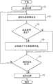
在前述的例子中,虽然说明了加速度传感器5的第1轴和第2轴被预先设定,但也可以构成为CPU 24单独地再设定预先设定的两个轴。图12示出了用于此的处理流程。In the aforementioned example, although it was described that the first axis and the second axis of the acceleration sensor 5 are preset, it may be configured such that the
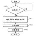
首先,CPU 24进行车辆1是否停止的判断(S30)。是否停止变成例如通过图11的处理流程求出的G值是否成为3秒以上0.1G以下的情况。或者,也可以在根据车速传感器的车速在指定速度(例如2Km/h)以下时判断为车辆停止。First, the
接着,CPU 24获得刚停止后的来自加速度传感器5的输出中设定为第1轴的输出G1和设定为第2轴的输出G2(S31),将在车辆1停止后车辆再次出发时的输出变成0.2G以上的轴认定为与车辆1的行进方向(或前后方向)平行的轴(S32)。Next, the
接着,CPU 24将在这次的判断中认定为与车辆1的行进方向平行的轴的轴作为经历信息存储在第2RAM 15中(S33)。Next, the
接着,CPU 24将在S32认定的轴以外的轴的输出认定为第2轴即车辆1的左右方向的输出(S34),结束一连串的处理。Next, the
图12所示的处理在每当判断车辆1停止时重复执行。如果图12所示的处理流程被执行了指定次数,则经历信息会被收集,因此,在轴的认定时,也可以根据经历信息进行。CPU 24,如图12所示,在通过轴方向的再设定进一步明确地特定了车辆1的左右方向的轴输出后,如图11所示,以从加速度传感器5的第2轴(车辆的左右方向)的输出G2的绝对值中减去指定的修正值α的方式进行用于防止转弯行驶时的误检测的修正。通过这种复合处理,可进一步防止转弯行驶时的误检测。另外,轴的设定不仅在停止时进行,也可以在出发时进行。在这种情况下,只要S30根据车速检测出例如5km/h以上就判断为已出发即可。此外,在S32中,只要将在刚判断为出发之后变成0.2G以上的轴确定为与车辆1的行进方向平行的轴即可。进一步地,经历信息也可以在向行车记录器2加上电源时被重置,并在每次加上电源时反复收集信息。The process shown in FIG. 12 is repeatedly executed every time it is determined that the
图13是示出作为记录条件成立的一个基准的G检测的处理流程的图。FIG. 13 is a diagram showing a processing flow of G detection, which is one criterion for the establishment of recording conditions.
首先,CPU 24进行通过图11的处理流程检测的G值一旦取得第1阈值(0.1G)以下的值后是否取得第2阈值(0.4G)以上的值的判断(S40)。在这种情况下,CPU 24判断为G检测的记录条件成立(S41)。第1阈值(0.1G)以及第2阈值(0.4G)是为了G检测而预先设定的值。此外,只将下降到第1阈值以下之后取得第2阈值以上的值的情况判断为记录条件成立的原因是当连续地检测出第2阈值以上的值时,加速度传感器5的异常、或车辆1翻转的状态等无需由于新的记录条件成立而记录影像信息的情况很多。First, the
接着,CPU 24进行是否如后面所述的延长正常的影像信息的记录(记录条件的成立前12秒以及成立后8秒)的判断(S42)。Next, the
在S42中,当没有延长时,检测从上一次记录条件成立开始的经过时间,并对照经过时间,进行下一个处理(S43)。In S42, if there is no extension, the elapsed time since the previous recording condition was satisfied is detected, and the elapsed time is compared to perform the next process (S43).
在S43中,从上一次记录条件成立开始的时间大于0秒且不到T1秒(例如4秒)时,不进行由于记录条件的成立引起的新记录和影像信息的记录时间的延长(S44)。即,忽略所检测的记录条件的成立。这是因为考虑到这是急刹车后的碰撞这一类的一系列事件,此外在太短时间里记录条件连续地成立时,由于对各个记录条件进行影像信息的记录,会导致重复记录影像信息。In S43, when the time from the establishment of the recording condition last time is greater than 0 seconds and less than T1 seconds (for example, 4 seconds), the new recording and the extension of the recording time of the image information due to the establishment of the recording condition are not performed (S44) . That is, the establishment of the detected recording condition is ignored. This is because it is considered that this is a series of events such as a collision after a sudden brake. In addition, when the recording conditions are continuously established in a short period of time, the image information will be recorded repeatedly due to the recording of image information for each recording condition. .
在S43中,在从上一次记录条件成立开始的时间是T1秒(例如4秒)以上且不到T2秒(例如8秒)时,将记录条件延长指定时间(例如4秒)(S45)。当在记录影像信息中记录条件再次成立时,即在上一次的记录条件成立后8秒间的后一半记录条件再次成立时,随后记录的影像信息将变少,因此,延长影像信息等的记录。这样,在S45的情况下,一次的记录变成记录条件的成立之前12秒和之后12秒的合计24秒。In S43, when the time since the previous recording condition was established is T1 seconds (for example, 4 seconds) or more and less than T2 seconds (for example, 8 seconds), the recording condition is extended for a specified time (for example, 4 seconds) (S45). When the recording condition is established again in the recording of image information, that is, when the recording condition is established again in the second half of the 8 seconds after the last recording condition is established, the amount of image information to be recorded subsequently will decrease, so the recording of image information, etc. . In this way, in the case of S45 , one recording is a total of 24 seconds of 12 seconds before and 12 seconds after the establishment of the recording condition.
在S43中,从上一次记录条件成立开始的时间是T2秒(例如8秒)以上时,作为新的记录条件的成立,进行该记录条件的成立之前12秒以及之后8秒之间的影像信息等的记录(S46)。另外,作为例外,当行车记录器2起动后记录条件首次成立时,也在S46中,进行该记录条件的成立之前12秒以及之后8秒之间的影像信息的记录。In S43, when the time from the establishment of the previous recording condition is more than T2 seconds (for example, 8 seconds), as a new recording condition is established, the image information between 12 seconds before and 8 seconds after the establishment of the recording condition is performed. etc. record (S46). In addition, as an exception, when the recording condition is satisfied for the first time after the start of the
在S42中,当判断为已经是延长中(S45)时,进一步考虑从上一次的记录条件的成立开始的经过时间(S47)。In S42, when it is judged that the extension is already in progress (S45), the elapsed time from the establishment of the previous recording condition is further considered (S47).
在S47中,当从上一次的记录条件的成立开始的时间是T2秒(例如8秒)以上且不到T3秒(例如12秒)时,不进行再次延长(S48)。即,忽略所检测的记录条件的成立。这是因为如果继续连续地延长,则将长时间地经历与一个事件有关的影像信息等的记录而造成记录过度。In S47, when the time since the last recording condition was established is T2 seconds (for example, 8 seconds) or more and less than T3 seconds (for example, 12 seconds), further extension is not performed (S48). That is, the establishment of the detected recording condition is ignored. This is because if the time is continuously extended, the recording of video information and the like related to one event will take a long time, resulting in excessive recording.
在S47中,当从上一次的记录条件的成立开始的时间在T3秒(例如12秒)以上时,作为新的记录条件的成立,进行该记录条件的成立之前12秒和之后8秒之间的影像信息等的记录(S49)。In S47, when the time from the establishment of the previous recording condition is more than T3 seconds (for example, 12 seconds), the establishment of the new recording condition is performed between 12 seconds before and 8 seconds after the establishment of the recording condition. Recording (S49) of image information etc.
按照图13的处理流程,使用图14~图17说明记录影像信息等的具体例子。A specific example of recording video information and the like will be described using FIGS. 14 to 17 according to the processing flow of FIG. 13 .
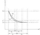
图14是示出根据G检测的影像信息的记录例子(1)的图。图14(a)是示出通过图11的处理流程求出的G值50的曲线图示例(1)的图,图14(b)是示出在第2RAM 15中循环记录的影像信息以及在存储卡6中记录的影像信息的图。FIG. 14 is a diagram showing a recording example (1) of image information detected by G. FIG. Fig. 14(a) is a diagram showing a graph example (1) of the
在t0,在一旦成为第1阈值以下之后,首次检测到第2阈值以上的G值,然后,在再次下降到第1阈值以下之后,在t1,第二次检测到第2阈值以上的G值。此外,从t0到t1是T2秒以上。At t0, after falling below the first threshold, a G value above the second threshold is detected for the first time, and after falling below the first threshold again, at t1, a G value above the second threshold is detected for the second time . In addition, it takes T2 seconds or more from t0 to t1.
根据图13的S46,在t0的记录条件成立,因此,t0之前12秒以及之后8秒间的影像信息52作为一个事件53记录在存储卡6中。此外,t1是在上一次t0开始T2秒以上之后,在t1发生时没有进行延长,因此,根据图13的S46,由于在t1的记录条件成立,t1之前12秒和之后8秒之间的影像信息54作为另一个事件55记录在存储卡6中。在事件53和事件55中,如图14(b)所示,包含重复的影像信息。According to S46 of FIG. 13 , the recording condition at t0 is satisfied, therefore, the
图15是示出根据G检测的影像信息的记录例子(2)的显示图。图15(a)是示出通过图11的处理流程求出的G值60的曲线图示例(2)的图,图15(b)是示出在第2RAM 15中循环记录的影像信息以及在存储卡6中记录的影像信息的图。FIG. 15 is a display diagram showing a recording example (2) of video information detected by G. FIG. Fig. 15(a) is a diagram showing a graph example (2) of the
在t0,在一旦成为第1阈值以下之后,首次检测到第2阈值以上的G值,然后,在再次下降到第1阈值以下之后,在t1,第二次检测到第2阈值以上的G值。然后,在再次下降到第1阈值以下之后,在t2,第三次检测到第2阈值以上的G值。此外,从t0到t1不足T2秒,从t0到t2是T3秒以上。At t0, after falling below the first threshold, a G value above the second threshold is detected for the first time, and after falling below the first threshold again, at t1, a G value above the second threshold is detected for the second time . Then, after falling below the first threshold again, at t2, a G value equal to or greater than the second threshold is detected for the third time. Also, the time from t0 to t1 is less than T2 seconds, and the time from t0 to t2 is more than T3 seconds.
根据图13的S46,在t0的记录条件成立,因此,t0之前12秒和之后8秒之间的影像信息62作为一个事件64记录在存储卡6中。此外,t1是从上一次的t0开始不满T2秒,在t1发生时没有进行延长,因此,根据图13的S45,在t1的记录条件成立,因此,4秒量的影像信息63作为延长量65记录在存储卡6中。进一步地,t2是在延长中,并且在从t0开始T3秒以上,因此,根据图13的S49,t2的记录条件成立,因此,t2之前12秒和之后8秒之间的影像信息等66作为另一个事件67记录在存储卡6中。在事件64和事件67中,如图15(b)所示,包括重复的影像信息。According to S46 of FIG. 13 , the recording condition at t0 is satisfied, and therefore, the
图16是示出根据G检测的影像信息的记录例子(3)的图。图16(a)是通过图11的处理流程求出的G值70的曲线图示例(3)的图,图16(b)是在第2RAM 15中循环记录的影像信息和在存储卡6中记录的影像信息的图。FIG. 16 is a diagram showing a recording example (3) of video information detected by G. Fig. 16 (a) is the figure of the graph example (3) of the
在t0,在一旦成为第1阈值以下之后,首次检测到第2阈值以上的G值,然后,在再次下降到第1阈值以下后,分别在t1、t2、t3和t4,检测到第2阈值以上的G值。此外,从t0到t1不足T1秒,从t0到t2不足T2秒,从t0到t3不足T3秒,从t0到t4在T3秒以上。At t0, after falling below the first threshold, a G value above the second threshold is detected for the first time, and then after falling below the first threshold again, at t1, t2, t3, and t4, respectively, the second threshold is detected above the G value. Also, the time from t0 to t1 is less than T1 seconds, the time from t0 to t2 is less than T2 seconds, the time from t0 to t3 is less than T3 seconds, and the time from t0 to t4 is longer than T3 seconds.
根据图13的S46,在t0的记录条件成立,因此,t0之前12秒和之后8秒之间的影像信息72作为一个事件74记录在存储卡6中。此外,由于t1不满T1秒,因此,根据图13的S44,t1被忽略。进一步地,t2是从t0开始不满T2秒,在t2发生时没有进行延长,因此,根据图13的S45,t2的记录条件成立,因此,4秒量的影像信息73作为延长量75记录在存储卡6中。进一步地,t3是在延长中,并且从t0开始不满T3秒,因此,根据图13的S48,t3被忽略。进一步地,t4是在延长中,并且在从t0开始T3秒以上,因此,根据图13的S49,在t4的记录条件成立,因此,t4之前12秒和之后8秒之间的影像信息76作为另一个事件77记录在存储卡6中。在事件74和事件77中,如图16(b)所示,包括重复的影像信息。According to S46 of FIG. 13 , the recording condition at t0 is established, and therefore,
图17是示出根据G检测的影像信息的记录例子(4)的图。图17(a)是示出通过图11的处理流程求出的G值80的曲线图示例(4)的图,图17(b)示出了在第2RAM 15中循环存储的影像信息以及在存储卡6中记录的影像信息。FIG. 17 is a diagram showing a recording example (4) of video information detected by G. Fig. 17(a) is a diagram showing an example (4) of the graph of the
在t0,在一旦成为第1阈值以下之后,首次检测到第2阈值以上的G值。然后,在再次下降到第1阈值以下之后,在t1中第二次检测到第2阈值以上的G值,但随后G值连续地示出高的数值。At t0, a G value equal to or greater than the second threshold is detected for the first time after once becoming equal to or less than the first threshold. Then, after falling below the first threshold again, a G value equal to or greater than the second threshold is detected for the second time at t1 , but the G value continues to show high numerical values after that.
根据图13的S46,在t0的记录条件成立,因此,t0之前12秒和之后8秒之间的影像信息等81作为一个事件82记录在存储卡6中。此外,由于t1不满T1秒,因此,根据图13的S44,t1被忽略。进一步地,由于随后没有下降到第1阈值以下,因此,根据图13的S40,即使检测到第2阈值以上的G值,也不视为记录条件成立。图17的例子相当于例如在t0进行急刹车操作而未能避开碰撞、在t1车辆1翻转并随后加速度传感器5由于翻转而继续输出高的G值这样的状态。According to S46 of FIG. 13 , the recording condition at t0 is satisfied, and therefore, the
以上,如基于图13至图17说明的,即使在检测到指定阈值以上的G值的情况下,也可以在记录条件连续地成立的情况或连续地检测到高的G值的情况下,进行控制以记录不必要的影像信息,因此,可有效地利用容量有限的存储卡6。As described above based on FIG. 13 to FIG. 17 , even when a G value equal to or greater than a specified threshold is detected, when recording conditions are continuously satisfied or when high G values are continuously detected, the Recording of unnecessary video information is controlled, so that the
对于行车记录器2的减电压处理,使用图18至图20说明。The voltage reduction process of the
所谓减电压处理是指在根据由于车辆1发生事故等造成的破损而降低来自电池21的输出电压的情况等下,为适当地保护记录中的影像信息而进行的处理。The voltage reduction processing refers to processing performed to properly protect video information being recorded when the output voltage from the
图18是示出减电压处理流程(1)的图。FIG. 18 is a diagram showing a voltage reduction processing flow (1).
CPU 24时常进行对来自第1检测部43(参照图6)的第1减电压信号S1是否从H变成L的监控(S50)。如图6中说明的,第1检测部43在电池21的输出电压下降到8.0伏以下时将第1减电压信号S1从H变更成L。The
在S50中,当第1减电压信号S1从H变化成L时,CPU 24使蜂鸣器26发生告警音(S51)。In S50, when the first voltage reduction signal S1 changes from H to L, the
接着,CPU 24进行当前记录条件是否成立、是否向存储卡6写入影像信息等的判断(S52),此外,进行在S50中检测到第1减电压的时间点是否从记录条件的成立开始经过指定时间(例如8秒)以上的判断(S53)。Next, the
当是影像信息的写入中并且从记录条件的成立开始未经过指定时间时,中断向存储卡的写入,记录从触发发生前10秒开始到触发发生为止的影像信息。此时,减少记录张数。将从检测到第1减电压前10秒开始到检测到第1减电压为止的影像信息在1秒间减少到5张(正常是1秒间10张),制成备份专用文件夹并向存储卡6进行写入(S54)。如果检测到第1减电压,则此后获得新的影像信息很困难的可能性高,因此,将在此之前获得的影像信息记录在备份专用文件夹中,并进行控制以尽可能不丢失在此之前的信息。另外,优选地,行驶信息也与影像信息一起记录在备份专用文件夹中。When the video information is being written and the specified time has not elapsed since the recording condition was established, the writing to the memory card is interrupted, and the video information from 10 seconds before the trigger occurs to the trigger is recorded. In this case, reduce the number of recording sheets. Reduce the image information from 10 seconds before the detection of the first voltage reduction to the detection of the first voltage reduction to 5 images in 1 second (normally 10 images in 1 second), make a backup folder and store it in the The
在S53,在经过了指定时间时,不进行特殊的备份处理。这是因为大致上正常的记录时间(记录条件的成立之前12秒以及记录条件的成立之后8秒)的影像信息获得完毕,因此可以正常地向存储卡6中记录。In S53, when the designated time has elapsed, no special backup processing is performed. This is because the video information has been obtained at approximately normal recording time (12 seconds before and 8 seconds after the recording condition is satisfied), and thus can be normally recorded to the
此后,CPU 24进行断开对第1照相机3、第2照相机4、构成图像处理电路13的JPEG-IC、GPS接收机9的电力供给的消费电力降低处理,确保预定的用于向存储卡6写入影像信息的电力(S55)。另外,用于进行S54中的备份处理的电力由备用电池46确保。Thereafter, the
接着,CPU 24在备份处理结束后,停止看门狗定时器,并进行重新启动(S56),结束一连串的处理。Then, after the backup process is completed, the
图19是示出减电压处理流程(2)的图。FIG. 19 is a diagram showing a voltage reduction processing flow (2).
CPU 24时常进行对来自第2检测部44(参照图6)的第2减电压信号S2是否从H变成L的监控(S60)。正如图6所说明的,第2检测部44在第1电源电路40的输出电压(或备用电池46的输出电压)下降到3.7伏以下时,将第2减电压信号S2从H变更到L。The
在S60中,当第2减电压信号S1从H变化成L时,CPU 24进行关闭处理的开始时期的确定(S61)。In S60, when the second voltage reduction signal S1 changes from H to L, the
图20示出电压下降状态的图。图20的曲线90示出电压从8.0伏开始下降到3.7伏为止耗费T4秒(从检测到第1减电压开始到检测到第2减电压为止的时间),从3.7伏开始到3.0伏为止耗费T5秒(从检测到第2减电压开始到重置信号输出为止的时间)。此外,图20的曲线91示出电压从8.0伏开始下降到3.7伏为止耗费T6秒,从3.7伏开始到3.0伏为止耗费T7秒。由于用于防止CPU 24等的误动作的重置信号以3.0伏从第3检测部45输出,因此,从第2减电压开始到输出重置信号为止耗费多少时间变得重要。如图20所示,根据从检测到第1减电压开始到检测到第2减电压为止的时间,可以进行从检测到第2减电压开始到输出重置信号为止的时间的大致预测。此外,对于关闭处理,大约500ms是必要的。Fig. 20 shows a diagram of a voltage drop state. The
因此,在电压从8.0伏开始下降到3.7伏为止的时间在1秒以上时,考虑到直到发生重信号为止耗费一定的时间,因此,在从检测到第2减电压开始1秒之后,开始进行关闭处理。此外,当电压从8.0伏开始下降到3.7伏为止的时间不足1秒时,由于重置信号提早发生的可能性高,因此,在刚检测到第2减电压之后就开始关闭处理。另外,上述的时间设定是一个例子,并不局限于此。Therefore, when the time for the voltage to drop from 8.0 volts to 3.7 volts is longer than 1 second, considering that it will take a certain amount of time until a heavy signal occurs, the process is started 1 second after the second voltage drop is detected. Close processing. Also, when the time for the voltage to drop from 8.0 volts to 3.7 volts is less than 1 second, since the reset signal is likely to occur early, the shutdown process starts immediately after the second voltage drop is detected. In addition, the time setting mentioned above is an example, and it is not limited to this.
接着,CPU 24在S61确定的开始时间开始关闭处理(S62)。所谓关闭处理是指用于关闭当前打开中的全部文件的处理,这样,向存储卡6中记录影像信息结束。在关闭处理之后,禁止向存储卡写入。另外,如果没有适当地执行关闭处理,则以后不能适当地利用在文件中记录的影像信息,因此,即使在如图18所示的备份处理当中,也中断备份处理,执行关闭处理。Next, the
然后,CPU 24在关闭处理结束后,停止看门狗定时器,进行重新启动(S63),结束一连串的处理。Then, after the shutdown process is completed, the
通过如图18至图20所示地适当地进行减电压处理,即使在由于事故等造成电池21的破损并断开行车记录器2和电池21之间的连接的情况下,也能够在存储卡6中记录尽可能多的影像信息等。By properly performing voltage reduction processing as shown in FIGS. 18 to 20 , even when the
图21是示出模式切换流程的图。FIG. 21 is a diagram showing a flow of mode switching.
行车记录器2被构成为具有用于与显示部30连接的输出端口,当事故等发生时,可以当场查证在存储卡6中记录的内容。即,本发明的行车记录器2具有:在存储卡6中记录影像信息等的记录模式和再现存储卡6中记录的影像信息的再现模式。使用图21对记录模式和再现模式的切换流程进行说明。The
首先,CPU 24在通过开闭传感器27检测到行车记录器2的开关旋钮3一旦变成开状态时(S70),启动用于行车记录器2的初始化的引导程序(S71)。First, when the
接着,当存储卡6被插入I/F 11中时,判断存储卡6是否被设定为写入禁止(S72)。当检测到是写入禁止时,CPU 24从非易失性ROM中下载再现模式用程序并使其启动,这样,在再现模式下,使行车记录器2工作(S73)。另外,当存储卡6被设定为写入禁止时,由于存储卡6的连接端子中的1个端口变成特定的输出,因此,可以经由I/F 11,在CPU 24中,进行存储卡6是否被设定成写入禁止的判断。Next, when the
接着,CPU 24通过LED 25和/或蜂鸣器26显示行车记录器2在再现模式下工作(S74),结束一连串的动作。Then, the
另一方面,在S72中,当存储卡6被插入I/F 11中但存储卡6没有被设定为写入禁止时,CPU 24从非易失性ROM中下载记录模式用程序,并使其启动,这样,使行车记录器2在记录模式中工作(S75)。On the other hand, in S72, when the
即,通常将存储卡6以可写入状态插入行车记录器2,设定为记录模式,并进行如前所述的由于记录条件的成立而引起的影像信息等的记录。然而,在由于事故等而当场查证记录内容时,一旦拔出存储卡6,并将存储卡6设定为写入禁止,则当再次插入行车记录器2时,能够使其变更成再现存储卡6中记录的影像信息的再生模式。另外,在行车记录器2和显示部30没有连接或显示部30破损时等,可以将便携用显示装置与行车记录器2的输出槽连接。此外,再现模式的设定方法并不局限于此。例如,可以考虑如果在电源加上后指定时间内对摄影开关8进行指定操作,则转换成再现模式,如果没有进行指定操作,则转换成记录模式等各种方法。That is, normally, the
下面对再现模式中影像信息的再现方法进行说明。Next, a method of reproducing video information in the reproducing mode will be described.
在图21的S74中,在通过LED 25和蜂鸣器26表示行车记录器2在再现模式中工作后,当用户按下摄影开关8时,蜂鸣器26停止,开始再现最后记录的事件。假设当此时15个事件被记录在存储卡6中时,开始再现最后的第15个事件,并在显示部30显示所记录的(一般情况下(没有延长的情况)20秒间量的)影像信息。在显示部30,优选地,与影像信息一起,至少还显示该影像信息是第几个事件以及记录条件成立的时刻。In S74 of FIG. 21 , after the
在再现事件的影像记录期间,再次按下摄影开关8,停止再现。此外,在再现停止期间,当再次按下摄影开关8时,从停止处的前1秒重新开始再现。进一步地,在与一个事件有关的影像信息的再现结束后,维持该状态,当再次按下摄影开关8时,重新开始与同一个事件有关的影像信息的再生。进一步地,当长按摄影开关8时,开始再现与下一个事件(即前一个所记录的事件)有关的影像信息。通过继续长按摄影开关8,可以再现存储卡6中记录的与所有事件有关的影像信息。以上是用于有效利用行车记录器2中具备的唯一一个作为操作装置的摄影开关8的方法,但也可以在行车记录器2中设置其它操作装置。During video recording of a playback event, pressing the shooting switch 8 again stops playback. Also, when the camera switch 8 is pressed again during playback stop, playback is restarted from 1 second before the stop. Furthermore, after the reproduction of the video information related to one event is completed, this state is maintained, and when the shooting switch 8 is pressed again, the reproduction of the video information related to the same event is resumed. Further, when the camera switch 8 is pressed for a long time, the video information related to the next event (ie, the previous recorded event) starts to be reproduced. By continuing to press the camera switch 8 for a long time, the video information related to all events recorded in the
此外,优选地,CPU 24当在进入再现模式后一定时间(例如30秒以上)没有操作摄影开关时,再次进行引导处理(参照S71)并重新启动。进一步地,优选地,在重新启动后,通过使蜂鸣器发声来对用户催促解除再现模式。In addition, it is preferable that the
图22是示出再现顺序的图。FIG. 22 is a diagram showing the playback sequence.
如图22所示,通过长按摄影开关8,可以控制从最后记录的第15个事件(S80)的再现到最先所拍摄的第1个事件(S85)的再现。另外,当在第1个事件的再生期间再次长按摄影开关8时,开始第15个事件的再现。As shown in FIG. 22, by long pressing the shooting switch 8, playback from the last recorded 15th event (S80) to the first recorded event (S85) can be controlled. In addition, when the shooting switch 8 is pressed and held again during the reproduction of the first event, the reproduction of the fifteenth event starts.
对再现装置400中存储卡6的利用进行说明。The use of the
图23是示出存储卡6的应用例流程的图。FIG. 23 is a diagram showing a flow of an application example of the
首先,用户将所使用的存储卡6设定为能够输入,并插入再现装置400的I/F 411进行卡的初始化(S90)。在卡的初始化中,通过CPU 424消除在此之前在存储卡6中记录的数据等,利用存储卡6进行运行的使用者(例如,出租车乘务员)的ID被写入存储卡6的指定地址。First, the user sets the
接着,用户在车辆1的运行开始时(例如,出租车乘务员在每日例行工作(7:45至17:15)开始时),设定为能够写入,将被初始化的存储卡6插入在车辆1上配置的行车记录器2的I/F 11,并将行车记录器2设为记录模式,开始数据记录(S91)。如前所述,CPU 24在记录条件成立时,将指定期间(例如20秒间)的影像信息和运行信息记录在存储卡6中。Next, when the user starts the operation of the vehicle 1 (for example, when a taxi attendant starts his daily routine work (7:45 to 17:15)), the user sets to enable writing, and inserts the initialized
接着,在车辆1的运行结束时(例如,出租车乘务员的每日工作结束时),结束数据记录,并将存储卡6从行车记录器2的I/F 11中取出。进一步地,用户将存储卡6插入再现装置400的I/F 411,在再现装置400一侧读入存储卡6中记录的影像信息、运行信息、存储卡的ID以及使用者的ID等(S92)Then, when the operation of the
在再现装置400一侧,通过CPU 424,对应于车辆1的运行,读入存储卡6中记录的影像信息、运行信息、存储卡的ID以及使用者的ID。在再现装置400中,也可以单独进行每个存储卡的数据的分析,也可以在从存储卡6中读入与多个车辆的多次运行对应的数据之后,集中进行数据的分析。进一步地,也可以将1张存储卡6用在多个车辆上,或者在多次运行中共用。On the reproducing
对再现装置400中视野区域的显示进行说明。The display of the viewing area in the
在行车记录器2中,虽然第1照相机3和第2照相机4获得影像信息,但实际上,驾驶者环视周围的视野与照相机固有的视野不同。In the
所谓的人的视野是指人不改变眼睛的位置而可环视的范围,通常,车辆1静止时的视野是指两眼合在一起,左右方向大约200度,垂直方向大约112度。此外,当车辆1的速度变化时,近处变得模糊,只看见远方,其结果,驾驶者的视野变窄。进一步地,视野有随着年龄变窄的倾向,因此,对于高龄的驾驶者和年轻人,视野是不同的。高龄者(例如60岁以上)的视野相对于年轻人(例如60岁以下)的视野,其范围变窄。作为例子,可考虑视野范围缩小20%。图24是示出在再现装置400中利用的水平方向和垂直方向的视角与车辆1的速度的对应表的图。由水平方向和垂直方向的视角规定的区域,即,驾驶者不转动眼睛能够看见的区域,被称为视野区域。The so-called human field of view refers to the range that a person can look around without changing the position of the eyes. Usually, the field of view of the
因此,再现装置400在再现行车记录器所获得的影像信息时,特定了驾驶者实际可看见的视野范围,可以查证事故等如何发生等。此外,通过特定视野范围,也可以用于进行对驾驶者的安全教育。Therefore, when the
在再现装置400中,在CPU 424基于控制程序417在显示部440显示与各事件有关的影像信息时,根据运行信息中的车速数据,检测车辆的速度,并根据图24所示的对应表(作为地图记录在再现装置400中)求出视角,并在画面上显示视野范围。In the
另外,在再现装置400中,具有以下5个视野范围再现模式,并通过操作部430的操作,用户通过其中一个模式,再现影像信息。In addition, the
1.固定角度模式:只显示与操作部430所指定的水平方向和垂直方向的视野角度对应的视野区域。1. Fixed angle mode: only the viewing area corresponding to the viewing angle in the horizontal direction and the vertical direction specified by the
2.检测瞬间车速模式:只显示与对应于在记录条件成立的时间点的车速的水平方向以及垂直方向的视野角度对应的视野区域。2. Instantaneous vehicle speed detection mode: display only the viewing area corresponding to the horizontal and vertical viewing angles corresponding to the vehicle speed at the time point when the recording condition is met.
3.再现位置的车速模式:依次显示与对应于所再现的每个静止图像的车速的水平方向以及垂直方向的视野角度对应的视野区域。3. Vehicle speed mode of reproduction position: sequentially display the field of view areas corresponding to the field of view angles in the horizontal direction and vertical direction corresponding to the vehicle speed of each reproduced still image.
4.固定速度模式:只显示与对应于操作部430所指定的速度的水平方向以及垂直方向的视野角度对应的视野区域。4. Fixed speed mode: only the viewing area corresponding to the viewing angle in the horizontal direction and the vertical direction corresponding to the speed designated by the
5.正常模式:不显示视野区域。5. Normal mode: the field of view is not displayed.
此外,在上述的检测瞬间车速模式(2)、再现位置的车速模式(3)以及固定速度模式(4)中,可以与高龄者修正进行组合。In addition, in the above-mentioned detecting instant vehicle speed mode (2), reproducing position vehicle speed mode (3), and fixed speed mode (4), it is possible to combine with elderly person correction.
图25是示出用于显示存储卡6中记录的影像信息的画面示例。另外,基于图25的画面的显示处理以及在画面上的用户的操作的处理是CPU424按照控制程序417,基于卡信息存储部460中存储的数据,在显示部440上显示的处理。FIG. 25 shows an example of a screen for displaying video information recorded in the
如图25所示,在显示部440所显示的画面140中,显示有存储卡6的ID号码数据141、在运行信息中包含的时刻信息142、表示所成立的记录条件的种类信息143、位置信息中的纬度数据144、位置信息中的经度数据145以及根据图11的流程求出的G值146、所显示的静止图像被拍摄时的后述的驾驶状况信息147、依次显示第1照相机3所拍摄的静止画面的区域148-1、依次显示第2照相机4所拍摄的静止画面的区域148-2、用于控制第1照相机3和第2照相机4所拍摄的静止画面用的操作按钮149(快退、再现、停止、快进)、所显示的静止图像被拍摄时的车速信息150、显示所选择的视野范围再现模式的种类的区域151、显示有或没有高龄者修正的区域152等。As shown in FIG. 25, on the
此外,在区域148-1中,显示有表示视野范围的第1框架153-1和表示进行高龄者修正的视野范围的第2框架153-2。同样,在区域148-2中,显示有表示视野范围的第1框架154-1和显示进行高龄者修正的视野范围的第2框架154-2。另外,在图25的例子中,如区域152所示,在虽然有高龄者修正但不进行高龄者修正时,不显示第2框架153-2和154-2。另外,在第1框架和第2框架的内外,通过使显示方法不同,可以明确显示视野范围。In addition, in the area 148-1, a first frame 153-1 showing the field of view range and a second frame 153-2 showing the field of view range for which the elderly correction is performed are displayed. Similarly, in the area 148-2, a first frame 154-1 showing the field of view range and a second frame 154-2 showing the field of view range for which correction for the elderly is displayed are displayed. In addition, in the example of FIG. 25, as shown in the
在图25的例子中,由于如区域151所示地选择检测瞬间车速模式,因此,将与在记录条件成立的时间点的车速(例如,40km/h)对应的与水平方向的视角(140度)和垂直方向的视角(78度)对应的视野区域作为第1框架153-1在区域148-1内显示(参照图24)。此外,将与在记录条件成立的时间点的车速(例如,40km/h)对应的与进行高龄者修正时的水平方向的视角(112度)和垂直方向的视角(63度)对应的视野区域作为第2框架153-2在区域148-1内显示(参照图24)。此外,对于区域148-2也是同样的。In the example of FIG. 25, since the detection instant vehicle speed mode is selected as shown in
在图25所示的画面140中,用户通过控制操作按钮149,可在区域148-1和148-2中依次切换显示第1照相机3所拍摄的10秒量的100张静止画面以及第2照相机4所拍摄的10秒量的100张静止画面。此外同时,与所显示的静止画面对应的信息在显示、输入区域141~147、150中显示。另外,图25所示的画面140是一个例子,也可以选择其它的画面构成。In the
在本实施方式中,如图25所示,由于与存储卡6中记录的影像信息重叠地显示视野区域,因此,驾驶者可以区别实际进入视野的区域和不是这个区域的区域,并查证在行车记录器2中获得的影像信息。此外,在根据年龄修正视野范围时,可以进一步将驾驶者的视野范围接近实际状况。In this embodiment, as shown in FIG. 25 , since the field of vision area is displayed superimposed on the image information recorded in the
另外,在图25中,虽然将记录条件和影像信息显示在同一个画面上,但也不是必须将两者都显示在同一个画面上,也可以例如在同一个画面上显示用于显示记录条件的操作按钮和画像,当操作该操作按钮时,将记录条件作为另一个窗口显示。In addition, in FIG. 25, although the recording condition and the image information are displayed on the same screen, it is not necessary to display both on the same screen. When the operation button and image are operated, the recording conditions are displayed as another window.
图26是示出驾驶状况分类处理流程的图。FIG. 26 is a diagram showing a flow of driving situation classification processing.
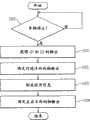
在存储卡6中,如前所述,记录了与指定的记录条件成立时的事件有关的影像信息。然而,对进行怎样的驾驶而记录条件成立进行分类在再现装置400中,当查证所记录的影像信息时是重要的。因此,在再现装置400中具有利用所记录的影像信息以及运行信息,按照图26所示的处理流程,自动分类各事件的功能。In the
进行分类的驾驶状况是“急起动”、“急刹车”、“正常刹车”、“左急转弯”、“右急转弯”5种。The driving situations classified are five types of "sudden start", "sudden braking", "normal braking", "sharp left turn", and "sharp right turn".
首先,CPU 424选择指定的方向盘,将与一方的照相机有关的与记录条件成立的时间点的前后30张静止图像的各个对应的G1值(加速度传感器5中与车辆1的前后方向平行的轴的输出)、G2值(加速度传感器5中与车辆1的左右方向平行的轴的输出)以及车速数据作为样本数据获得(S100)。First, the
接着,CPU 424对于每一个样本,对该样本的前后10点的值应用最小二乘法,算出各个样本的变化的倾斜度(S101)。进一步地,特定记录条件成立前后的各个样本的倾斜波形的峰值(S102)。Next, the
接着,CPU 424根据后述的特定预先确定的各驾驶状况的峰值主文件和在S92求出的峰值的关系,特定作为对象的事件的驾驶状况(S103),结束一连串的处理。另外,关于各个事件特定的驾驶状况在与各事件有关的影像信息在显示部440上显示时进行显示(参照图25的区域147)。此外,所特定的驾驶状况作为对每个驾驶状况设定的图标在图像上的例如右上方与图像重叠地显示。这样,可以确切地掌握再现中的事件的驾驶状况。此外,可以在驾驶状况的分类中搜索事件并缩小。这样,可以只抽出想确认的驾驶状况并再现图像。Next, the
图27是示出样本线等的图。纵轴表示G1值,横轴表示时间,T=0的时间点对应记录条件成立的时刻。FIG. 27 is a diagram showing sample lines and the like. The vertical axis represents the G1 value, and the horizontal axis represents time, and the time point of T=0 corresponds to the time when the recording condition is established.
在图27中显示了按照图26的S100获得的与指定事件有关的G1值的样本线200。此外,波形210是将依照图26的S101求出的构成样本线200的各个样本的倾斜度连接在一起的倾斜波形。进一步地,点220表示记录条件成立前的波形210的峰值,点230表示记录条件成立后的波形210的峰值。A
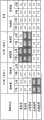
图28是示出峰值主文件的一个例子的图。Fig. 28 is a diagram showing an example of a peak master file.
如图28所示,与对应于前述的5个驾驶状况的G1值、G2值以及车速有关的峰值(参照图26的S102)覆盖的范围,即上限和下限,对记录条件成立时的前后进行规定。通过特定在图26的S102特定的峰值进入图28的各驾驶状况的哪个上下限内的范围特定驾驶状况(图26的S103)。另外,在图28中,网格部分是规定有峰值的部分,在其它地方未规定峰值。As shown in Figure 28, the range covered by the peak value (refer to S102 of Figure 26) related to the G1 value, G2 value and vehicle speed corresponding to the aforementioned five driving situations, that is, the upper limit and the lower limit, is performed before and after the record condition is established. Regulation. The driving situation is specified by specifying the range in which the peak value specified in S102 of FIG. 26 falls within the upper and lower limits of each driving situation in FIG. 28 (S103 of FIG. 26 ). In addition, in FIG. 28, the grid portion is a portion where peaks are specified, and peaks are not specified in other places.
例如,在图27的例子中,当与G1值有关的波形210的点220的值是1.5,点230的值是-1.5时,根据图28的峰值主文件,判断为是“急刹车”的驾驶状况。For example, in the example of Fig. 27, when the value of
另外,优选地,图28所示的峰值主文件中规定的各个值能够利用图29所示的在显示部440上显示的编辑画面160进行修正。另外,图29所示的编辑画面160是用于修正与急起动有关的条件。此外,图28所示的峰值主文件中规定的值是一个例子,也可以采用其它值,此外,也可以加入车速作为条件。In addition, it is preferable that each value specified in the peak master file shown in FIG. 28 can be corrected using the
图30是示出表示急起动的驾驶状况的典型样式的图。FIG. 30 is a diagram showing a typical pattern of a driving situation representing a sudden start.
图30(a)示出G2值的样本线300,图30(b)示出G1值的样本线301,图30(c)示出车速的样本线302。在任何一个图中,记录条件的成立时刻都设为T=0。FIG. 30( a ) shows a
根据G1值、G2值和车速的样本线,分别求出各样本的倾斜波形,并根据这些记录条件成立前后的峰值,判断驾驶状况。在图30的情况下,根据G1值的样本线301求出各样本的倾斜波形303,并根据该记录条件的成立前的峰值304在-0.2~-2.0之间,判断为急起动。According to the sample line of G1 value, G2 value and vehicle speed, the slope waveform of each sample is obtained respectively, and the driving condition is judged according to the peak value before and after the establishment of these recording conditions. In the case of FIG. 30 , the
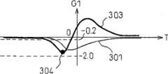
图31是示出表示急刹车的驾驶状况的典型样式的图。FIG. 31 is a diagram showing a typical pattern showing a driving situation of sudden braking.
图31(a)示出G2值的样本线310,图31(b)示出G1值的样本线311,图31(c)示出车速的样本线312。在任何一个图中,记录条件的成立时刻设为T=0。FIG. 31( a ) shows a
根据G1值、G2值和车速的样本线,分别求出各样本的倾斜波形,并根据这些记录条件成立前后的峰值,判断驾驶状况。在图31的情况下,根据G1值的样本线311求出各样本的倾斜波形313,并根据该记录条件的成立前的峰值314在3.0~0.5之间、该记录条件的成立后的峰值315在-0.4~-3.0之间,判断为急刹车。According to the sample line of G1 value, G2 value and vehicle speed, the slope waveform of each sample is obtained respectively, and the driving condition is judged according to the peak value before and after the establishment of these recording conditions. In the case of FIG. 31 , the
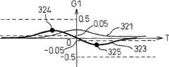
图32是示出表示正常刹车的驾驶状况的典型样式的图。FIG. 32 is a diagram showing a typical pattern of a driving situation representing normal braking.
图32(a)示出G2值的样本线320,图32(b)示出G1值的样本线321,图32(c)示出车速的样本线322。在任意一个图中,记录条件的成立时刻设为T=0。FIG. 32( a ) shows a sample line 320 of the G2 value, FIG. 32( b ) shows a
根据G1值、G2值和车速的样本线分别求出各样本的倾斜波形,并根据这些记录条件成立前后的峰值,判断驾驶状况。在图32的情况下,根据G1值的样本线321求出各样本的倾斜波形323,并根据该记录条件的成立前的峰值324在0.5~0.05之间、该记录条件的成立后的峰值325在-0.05~-0.5之间,判断为正常刹车。According to the sample line of G1 value, G2 value and vehicle speed, the slope waveform of each sample is obtained respectively, and the driving condition is judged according to the peak value before and after the establishment of these recording conditions. In the case of FIG. 32 , the
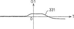
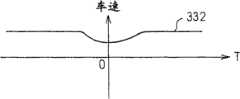
图33是示出表示左急转弯的驾驶状况的典型样式的图。FIG. 33 is a diagram showing a typical pattern of a driving situation representing a sharp left turn.
图33(a)示出G2值的样本线330,图33(b)示出G1值的样本线331,图33(c)示出车速的样本线332。在任意一个图中,记录条件的成立时刻设为T=0。FIG. 33( a ) shows a
根据G1值、G2值和车速的样本线分别求出各样本的倾斜波形,并根据这些记录条件成立前后的峰值,判断驾驶状况。在图33的情况下,根据G2值的样本线330求出各样本的倾斜波形333,并根据该记录条件的成立前的峰值334在2.0~0.1之间,判断为左急转弯。According to the sample line of G1 value, G2 value and vehicle speed, the slope waveform of each sample is obtained respectively, and the driving condition is judged according to the peak value before and after the establishment of these recording conditions. In the case of FIG. 33 , the
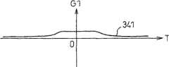
图34是示出表示右急转弯的驾驶状况的典型样式的图。FIG. 34 is a diagram showing a typical pattern of a driving situation representing a sharp right turn.
图34(a)示出G2值的样本线340,图34(b)示出G1值的样本线341,图34(c)示出车速样本线342。在任意一个图中,记录条件的成立时刻设为T=0。FIG. 34( a ) shows a
根据G1值、G2值和车速的样本线分别求出各样本的倾斜波形,并基于这些记录条件成立前后的峰值,判断驾驶状况。在图34的情况下,根据G2值的样本线340求出各样本的倾斜波形343,并根据该记录条件的成立前的峰值344在-0.1~-2.0之间,判断为右急转弯。Based on the sample lines of G1 value, G2 value and vehicle speed, the slope waveform of each sample is obtained respectively, and the driving condition is judged based on the peak values before and after these recording conditions are met. In the case of FIG. 34 , the
如上所述,关于各事件,可以对影像信息被记录的情况下的驾驶状况进行分类,因此,在再现装置400中,可进一步定量地进行数据的查证。As described above, for each event, it is possible to classify the driving situation when the video information is recorded, and therefore, in the
Claims (7)
Applications Claiming Priority (5)
| Application Number | Priority Date | Filing Date | Title |
|---|---|---|---|
| JP2007256243AJP2009087066A (en) | 2007-09-28 | 2007-09-28 | Drive recorder setting method |
| JP2007255900AJP4679558B2 (en) | 2007-09-28 | 2007-09-28 | Drive recorder |
| JP255900/2007 | 2007-09-28 | ||
| JP256243/2007 | 2007-09-28 | ||
| PCT/JP2008/068007WO2009041738A1 (en) | 2007-09-28 | 2008-09-26 | Drive recorder and setting method for the same |
Publications (2)
| Publication Number | Publication Date |
|---|---|
| CN101809629A CN101809629A (en) | 2010-08-18 |
| CN101809629Btrue CN101809629B (en) | 2012-11-21 |
Family
ID=40511607
Family Applications (1)
| Application Number | Title | Priority Date | Filing Date |
|---|---|---|---|
| CN200880108959XAActiveCN101809629B (en) | 2007-09-28 | 2008-09-26 | Drive recorder and setting method for the same |
Country Status (3)
| Country | Link |
|---|---|
| US (1) | US8396623B2 (en) |
| CN (1) | CN101809629B (en) |
| WO (1) | WO2009041738A1 (en) |
Cited By (1)
| Publication number | Priority date | Publication date | Assignee | Title |
|---|---|---|---|---|
| CN106355670A (en)* | 2015-07-16 | 2017-01-25 | 群光电子股份有限公司 | Driving recorder and starting and sleeping control method thereof |
Families Citing this family (55)
| Publication number | Priority date | Publication date | Assignee | Title |
|---|---|---|---|---|
| US20070150138A1 (en)* | 2005-12-08 | 2007-06-28 | James Plante | Memory management in event recording systems |
| US10878646B2 (en) | 2005-12-08 | 2020-12-29 | Smartdrive Systems, Inc. | Vehicle event recorder systems |
| FR2895726B1 (en)* | 2006-01-03 | 2009-10-23 | Thales Sa | SYSTEM AND METHOD FOR ASSISTING THE BRAKING OF AN AIRCRAFT ON A LANDING TRAIL |
| US8996240B2 (en) | 2006-03-16 | 2015-03-31 | Smartdrive Systems, Inc. | Vehicle event recorders with integrated web server |
| US9201842B2 (en) | 2006-03-16 | 2015-12-01 | Smartdrive Systems, Inc. | Vehicle event recorder systems and networks having integrated cellular wireless communications systems |
| US7873200B1 (en) | 2006-10-31 | 2011-01-18 | United Services Automobile Association (Usaa) | Systems and methods for remote deposit of checks |
| US8708227B1 (en) | 2006-10-31 | 2014-04-29 | United Services Automobile Association (Usaa) | Systems and methods for remote deposit of checks |
| US8649933B2 (en) | 2006-11-07 | 2014-02-11 | Smartdrive Systems Inc. | Power management systems for automotive video event recorders |
| US8989959B2 (en) | 2006-11-07 | 2015-03-24 | Smartdrive Systems, Inc. | Vehicle operator performance history recording, scoring and reporting systems |
| US8868288B2 (en) | 2006-11-09 | 2014-10-21 | Smartdrive Systems, Inc. | Vehicle exception event management systems |
| US8239092B2 (en) | 2007-05-08 | 2012-08-07 | Smartdrive Systems Inc. | Distributed vehicle event recorder systems having a portable memory data transfer system |
| US9058512B1 (en) | 2007-09-28 | 2015-06-16 | United Services Automobile Association (Usaa) | Systems and methods for digital signature detection |
| US9159101B1 (en) | 2007-10-23 | 2015-10-13 | United Services Automobile Association (Usaa) | Image processing |
| US10380562B1 (en) | 2008-02-07 | 2019-08-13 | United Services Automobile Association (Usaa) | Systems and methods for mobile deposit of negotiable instruments |
| US8229630B2 (en)* | 2008-02-11 | 2012-07-24 | Infineon Technologies Ag | Electronic airbag control unit having an autonomous event data recorder |
| US10504185B1 (en) | 2008-09-08 | 2019-12-10 | United Services Automobile Association (Usaa) | Systems and methods for live video financial deposit |
| US8520070B1 (en) | 2008-10-30 | 2013-08-27 | Rosco Inc. | Method and system with multiple camera units installed in protective enclosure |
| US8452689B1 (en) | 2009-02-18 | 2013-05-28 | United Services Automobile Association (Usaa) | Systems and methods of check detection |
| US10956728B1 (en) | 2009-03-04 | 2021-03-23 | United Services Automobile Association (Usaa) | Systems and methods of check processing with background removal |
| US9779392B1 (en) | 2009-08-19 | 2017-10-03 | United Services Automobile Association (Usaa) | Apparatuses, methods and systems for a publishing and subscribing platform of depositing negotiable instruments |
| US8880281B2 (en)* | 2010-03-01 | 2014-11-04 | GM Global Technology Operations LLC | Event data recorder system and method |
| US9129340B1 (en) | 2010-06-08 | 2015-09-08 | United Services Automobile Association (Usaa) | Apparatuses, methods and systems for remote deposit capture with enhanced image detection |
| CN102145683A (en)* | 2011-03-11 | 2011-08-10 | 广东铁将军防盗设备有限公司 | vehicle video recorder |
| US20120303533A1 (en) | 2011-05-26 | 2012-11-29 | Michael Collins Pinkus | System and method for securing, distributing and enforcing for-hire vehicle operating parameters |
| US20130060721A1 (en) | 2011-09-02 | 2013-03-07 | Frias Transportation Infrastructure, Llc | Systems and methods for pairing of for-hire vehicle meters and medallions |
| US9037852B2 (en) | 2011-09-02 | 2015-05-19 | Ivsc Ip Llc | System and method for independent control of for-hire vehicles |
| US10380565B1 (en) | 2012-01-05 | 2019-08-13 | United Services Automobile Association (Usaa) | System and method for storefront bank deposits |
| US20130253999A1 (en) | 2012-03-22 | 2013-09-26 | Frias Transportation Infrastructure Llc | Transaction and communication system and method for vendors and promoters |
| US9728228B2 (en) | 2012-08-10 | 2017-08-08 | Smartdrive Systems, Inc. | Vehicle event playback apparatus and methods |
| JP6057605B2 (en)* | 2012-08-14 | 2017-01-11 | 株式会社パイ・アール | Drive recorder |
| KR101337940B1 (en)* | 2012-08-16 | 2013-12-09 | 현대자동차주식회사 | Method for preventing trip data clear of vehicle |
| US11138578B1 (en) | 2013-09-09 | 2021-10-05 | United Services Automobile Association (Usaa) | Systems and methods for remote deposit of currency |
| US9501878B2 (en) | 2013-10-16 | 2016-11-22 | Smartdrive Systems, Inc. | Vehicle event playback apparatus and methods |
| US9286514B1 (en) | 2013-10-17 | 2016-03-15 | United Services Automobile Association (Usaa) | Character count determination for a digital image |
| US9610955B2 (en) | 2013-11-11 | 2017-04-04 | Smartdrive Systems, Inc. | Vehicle fuel consumption monitor and feedback systems |
| US8892310B1 (en) | 2014-02-21 | 2014-11-18 | Smartdrive Systems, Inc. | System and method to detect execution of driving maneuvers |
| CN104599545B (en)* | 2014-05-19 | 2017-06-30 | 腾讯科技(深圳)有限公司 | For the driving states monitoring method in driving conditions, device and navigation equipment |
| US9663127B2 (en) | 2014-10-28 | 2017-05-30 | Smartdrive Systems, Inc. | Rail vehicle event detection and recording system |
| US11069257B2 (en) | 2014-11-13 | 2021-07-20 | Smartdrive Systems, Inc. | System and method for detecting a vehicle event and generating review criteria |
| WO2016085830A1 (en)* | 2014-11-25 | 2016-06-02 | Horvath Jon Patrik | Movement and distance triggered image recording system |
| US9718405B1 (en) | 2015-03-23 | 2017-08-01 | Rosco, Inc. | Collision avoidance and/or pedestrian detection system |
| US9679420B2 (en) | 2015-04-01 | 2017-06-13 | Smartdrive Systems, Inc. | Vehicle event recording system and method |
| US10506281B1 (en) | 2015-12-22 | 2019-12-10 | United Services Automobile Association (Usaa) | System and method for capturing audio or video data |
| US10504302B1 (en)* | 2015-12-22 | 2019-12-10 | United Services Automobile Association (Usaa) | 360 degree vehicle camera accident monitoring system |
| CN105681873B (en)* | 2016-02-04 | 2019-03-22 | 盯盯拍(深圳)云技术有限公司 | Video playback method and system based on map track |
| US10325420B1 (en) | 2016-03-10 | 2019-06-18 | United Services Automobile Association (Usaa) | VIN scan recall notification |
| US9994174B2 (en)* | 2016-09-27 | 2018-06-12 | Auto-Linked Shanghai Info Technology Co., Ltd. | Smart power supply interface, vehicle-mounted electronic component with the same and method of controlling the same |
| JP6608345B2 (en)* | 2016-09-28 | 2019-11-20 | 日立建機株式会社 | Work machine |
| WO2018092388A1 (en)* | 2016-11-21 | 2018-05-24 | パナソニックIpマネジメント株式会社 | Speed enforcement system and speed enforcement method |
| JP6569698B2 (en)* | 2017-04-17 | 2019-09-04 | 株式会社Jvcケンウッド | Recording control apparatus, recording apparatus, navigation apparatus, recording method, and program |
| JP7043785B2 (en) | 2017-10-25 | 2022-03-30 | 株式会社Ihi | Information generator |
| US11030752B1 (en) | 2018-04-27 | 2021-06-08 | United Services Automobile Association (Usaa) | System, computing device, and method for document detection |
| JP7140037B2 (en) | 2019-04-15 | 2022-09-21 | トヨタ自動車株式会社 | Vehicle remote indication system |
| CN111358472B (en)* | 2020-03-27 | 2022-08-23 | 山东建筑大学 | Gait detection algorithm, device and system |
| US11900755B1 (en) | 2020-11-30 | 2024-02-13 | United Services Automobile Association (Usaa) | System, computing device, and method for document detection and deposit processing |
Citations (4)
| Publication number | Priority date | Publication date | Assignee | Title |
|---|---|---|---|---|
| CN1704976A (en)* | 2004-06-02 | 2005-12-07 | 乐金电子(惠州)有限公司 | Accident recording apparatus and method for vehicle |
| CN2751362Y (en)* | 2004-11-23 | 2006-01-11 | 王刚 | Visible black box |
| CN1811825A (en)* | 2005-01-21 | 2006-08-02 | 三洋电机株式会社 | Drive recorder and control method therefor |
| CN1858551A (en)* | 2006-05-26 | 2006-11-08 | 浙江工业大学 | Engineering car anti-theft alarm system based on omnibearing computer vision |
Family Cites Families (24)
| Publication number | Priority date | Publication date | Assignee | Title |
|---|---|---|---|---|
| JPH04130275A (en)* | 1990-09-20 | 1992-05-01 | Nissan Motor Co Ltd | Offset elimination device of acceleration sensor |
| US5446658A (en)* | 1994-06-22 | 1995-08-29 | General Motors Corporation | Method and apparatus for estimating incline and bank angles of a road surface |
| JPH08268257A (en)* | 1995-03-30 | 1996-10-15 | Isuzu Motors Ltd | Actual speed estimator |
| JP3272960B2 (en)* | 1996-08-19 | 2002-04-08 | 株式会社データ・テック | Driving recorder and vehicle operation analyzer |
| JP3619347B2 (en)* | 1997-04-26 | 2005-02-09 | パイオニア株式会社 | Navigation system and polarity switching method |
| JP3485239B2 (en) | 1997-09-10 | 2004-01-13 | 富士重工業株式会社 | Vehicle motion control device |
| US6718239B2 (en)* | 1998-02-09 | 2004-04-06 | I-Witness, Inc. | Vehicle event data recorder including validation of output |
| US6389340B1 (en)* | 1998-02-09 | 2002-05-14 | Gary A. Rayner | Vehicle data recorder |
| JP3509631B2 (en)* | 1999-05-28 | 2004-03-22 | トヨタ自動車株式会社 | Vehicle data recording device |
| JP2001050973A (en) | 1999-08-04 | 2001-02-23 | Denso Corp | Method and device for estimating and for controlling behavior of vehicle |
| US20020107912A1 (en)* | 2001-02-08 | 2002-08-08 | Lear Corporation | Motor vehicle drive recorder system which records motor vehicle data proximate an event declared by a motor veicle occupant |
| JP3984863B2 (en) | 2002-05-13 | 2007-10-03 | 三菱電機株式会社 | Start notification device |
| US7042663B2 (en)* | 2002-10-03 | 2006-05-09 | Hitachi Global Storage Technologies Netherlands B.V. | Magnetic disk protection mechanism, computer system comprising protection mechanism, protection method for magnetic disk, and program for protection method |
| JP4347760B2 (en) | 2004-07-07 | 2009-10-21 | 株式会社データ・テック | Mobile operation management method, system and component device thereof |
| US8452502B2 (en)* | 2005-07-01 | 2013-05-28 | Japan Automobile Research Institute | Driving recorder |
| JP4025347B2 (en)* | 2005-11-14 | 2007-12-19 | 富士通テン株式会社 | Driving information recording device |
| JP4903443B2 (en)* | 2006-01-23 | 2012-03-28 | 富士通テン株式会社 | Drive recorder |
| WO2007091723A1 (en)* | 2006-02-07 | 2007-08-16 | National University Corporation Tokyo University Of Agriculture And Technology | Vehicle operation measuring device, vehicle abnormal operation preventing device, and drive recorder |
| JP2007311904A (en)* | 2006-05-16 | 2007-11-29 | Victor Co Of Japan Ltd | Drive recorder, video image correction method thereof, drive recorder, and system thereof |
| JP4661734B2 (en)* | 2006-08-24 | 2011-03-30 | 株式会社デンソー | In-vehicle warning system |
| DE102006045304A1 (en)* | 2006-09-26 | 2008-04-03 | Siemens Ag | Method and apparatus for estimating the center of gravity of a vehicle |
| US7957863B2 (en)* | 2006-11-10 | 2011-06-07 | Fujitsu Ten Limited | Vehicle information recording apparatus, program, and recording medium |
| JP4439550B2 (en)* | 2007-09-28 | 2010-03-24 | 富士通テン株式会社 | Drive recorder |
| JP4679558B2 (en) | 2007-09-28 | 2011-04-27 | 富士通テン株式会社 | Drive recorder |
- 2008
- 2008-09-26CNCN200880108959XApatent/CN101809629B/enactiveActive
- 2008-09-26USUS12/680,542patent/US8396623B2/enactiveActive
- 2008-09-26WOPCT/JP2008/068007patent/WO2009041738A1/enactiveApplication Filing
Patent Citations (4)
| Publication number | Priority date | Publication date | Assignee | Title |
|---|---|---|---|---|
| CN1704976A (en)* | 2004-06-02 | 2005-12-07 | 乐金电子(惠州)有限公司 | Accident recording apparatus and method for vehicle |
| CN2751362Y (en)* | 2004-11-23 | 2006-01-11 | 王刚 | Visible black box |
| CN1811825A (en)* | 2005-01-21 | 2006-08-02 | 三洋电机株式会社 | Drive recorder and control method therefor |
| CN1858551A (en)* | 2006-05-26 | 2006-11-08 | 浙江工业大学 | Engineering car anti-theft alarm system based on omnibearing computer vision |
Cited By (1)
| Publication number | Priority date | Publication date | Assignee | Title |
|---|---|---|---|---|
| CN106355670A (en)* | 2015-07-16 | 2017-01-25 | 群光电子股份有限公司 | Driving recorder and starting and sleeping control method thereof |
Also Published As
| Publication number | Publication date |
|---|---|
| WO2009041738A1 (en) | 2009-04-02 |
| US8396623B2 (en) | 2013-03-12 |
| US20100250060A1 (en) | 2010-09-30 |
| CN101809629A (en) | 2010-08-18 |
Similar Documents
| Publication | Publication Date | Title |
|---|---|---|
| CN101809629B (en) | Drive recorder and setting method for the same | |
| JP5057917B2 (en) | Drive recorder | |
| US8421862B2 (en) | Drive recorder | |
| JP4439550B2 (en) | Drive recorder | |
| JP4439548B2 (en) | Drive recorder | |
| CN101821778A (en) | Driving state display method | |
| US20100134623A1 (en) | Method of processing continuously recorded image, computer-readable medium for processing continuously recorded image, drive recorder and reproduction device | |
| JP4439551B2 (en) | Vehicle running status display method | |
| CN101739739A (en) | Drive recorder | |
| JP4859756B2 (en) | Image recording condition setting method in drive recorder | |
| JP5036787B2 (en) | Drive recorder | |
| JP4679558B2 (en) | Drive recorder | |
| JP5322680B2 (en) | Drive recorder | |
| JP4439549B2 (en) | Drive recorder | |
| JP2010183464A (en) | Drive recorder | |
| JP4503062B2 (en) | Playback device | |
| JP4931979B2 (en) | Drive recorder | |
| JP2009301280A (en) | Drive recorder | |
| JP4531085B2 (en) | Drive recorder | |
| JP4684272B2 (en) | Drive recorder | |
| WO2009041721A1 (en) | Drive recorder | |
| JP2009087066A (en) | Drive recorder setting method | |
| JP2009301106A (en) | Drive recorder | |
| JP2010128984A (en) | Memory card reading control device and program |
Legal Events
| Date | Code | Title | Description |
|---|---|---|---|
| C06 | Publication | ||
| PB01 | Publication | ||
| C10 | Entry into substantive examination | ||
| SE01 | Entry into force of request for substantive examination | ||
| C14 | Grant of patent or utility model | ||
| GR01 | Patent grant |