CN101809593A - Signal line structure for RFID system - Google Patents
Signal line structure for RFID systemDownload PDFInfo
- Publication number
- CN101809593A CN101809593ACN200880108735ACN200880108735ACN101809593ACN 101809593 ACN101809593 ACN 101809593ACN 200880108735 ACN200880108735 ACN 200880108735ACN 200880108735 ACN200880108735 ACN 200880108735ACN 101809593 ACN101809593 ACN 101809593A
- Authority
- CN
- China
- Prior art keywords
- shelf
- signal line
- rfid
- signal
- signal wire
- Prior art date
- Legal status (The legal status is an assumption and is not a legal conclusion. Google has not performed a legal analysis and makes no representation as to the accuracy of the status listed.)
- Granted
Links
Images


Classifications
- G—PHYSICS
- G06—COMPUTING OR CALCULATING; COUNTING
- G06K—GRAPHICAL DATA READING; PRESENTATION OF DATA; RECORD CARRIERS; HANDLING RECORD CARRIERS
- G06K7/00—Methods or arrangements for sensing record carriers, e.g. for reading patterns
- G06K7/0008—General problems related to the reading of electronic memory record carriers, independent of its reading method, e.g. power transfer
- G—PHYSICS
- G06—COMPUTING OR CALCULATING; COUNTING
- G06K—GRAPHICAL DATA READING; PRESENTATION OF DATA; RECORD CARRIERS; HANDLING RECORD CARRIERS
- G06K7/00—Methods or arrangements for sensing record carriers, e.g. for reading patterns
- G06K7/10—Methods or arrangements for sensing record carriers, e.g. for reading patterns by electromagnetic radiation, e.g. optical sensing; by corpuscular radiation
- G06K7/10009—Methods or arrangements for sensing record carriers, e.g. for reading patterns by electromagnetic radiation, e.g. optical sensing; by corpuscular radiation sensing by radiation using wavelengths larger than 0.1 mm, e.g. radio-waves or microwaves
- G06K7/10316—Methods or arrangements for sensing record carriers, e.g. for reading patterns by electromagnetic radiation, e.g. optical sensing; by corpuscular radiation sensing by radiation using wavelengths larger than 0.1 mm, e.g. radio-waves or microwaves using at least one antenna particularly designed for interrogating the wireless record carriers
- G—PHYSICS
- G06—COMPUTING OR CALCULATING; COUNTING
- G06Q—INFORMATION AND COMMUNICATION TECHNOLOGY [ICT] SPECIALLY ADAPTED FOR ADMINISTRATIVE, COMMERCIAL, FINANCIAL, MANAGERIAL OR SUPERVISORY PURPOSES; SYSTEMS OR METHODS SPECIALLY ADAPTED FOR ADMINISTRATIVE, COMMERCIAL, FINANCIAL, MANAGERIAL OR SUPERVISORY PURPOSES, NOT OTHERWISE PROVIDED FOR
- G06Q10/00—Administration; Management
- G06Q10/08—Logistics, e.g. warehousing, loading or distribution; Inventory or stock management
- G—PHYSICS
- G08—SIGNALLING
- G08B—SIGNALLING OR CALLING SYSTEMS; ORDER TELEGRAPHS; ALARM SYSTEMS
- G08B13/00—Burglar, theft or intruder alarms
- G08B13/22—Electrical actuation
- G08B13/24—Electrical actuation by interference with electromagnetic field distribution
- G08B13/2402—Electronic Article Surveillance [EAS], i.e. systems using tags for detecting removal of a tagged item from a secure area, e.g. tags for detecting shoplifting
- G08B13/2465—Aspects related to the EAS system, e.g. system components other than tags
- G08B13/2468—Antenna in system and the related signal processing
- G08B13/2474—Antenna or antenna activator geometry, arrangement or layout
- H—ELECTRICITY
- H01—ELECTRIC ELEMENTS
- H01Q—ANTENNAS, i.e. RADIO AERIALS
- H01Q1/00—Details of, or arrangements associated with, antennas
- H01Q1/12—Supports; Mounting means
- H01Q1/22—Supports; Mounting means by structural association with other equipment or articles
- H01Q1/2208—Supports; Mounting means by structural association with other equipment or articles associated with components used in interrogation type services, i.e. in systems for information exchange between an interrogator/reader and a tag/transponder, e.g. in Radio Frequency Identification [RFID] systems
- H01Q1/2216—Supports; Mounting means by structural association with other equipment or articles associated with components used in interrogation type services, i.e. in systems for information exchange between an interrogator/reader and a tag/transponder, e.g. in Radio Frequency Identification [RFID] systems used in interrogator/reader equipment
- H—ELECTRICITY
- H01—ELECTRIC ELEMENTS
- H01Q—ANTENNAS, i.e. RADIO AERIALS
- H01Q13/00—Waveguide horns or mouths; Slot antennas; Leaky-waveguide antennas; Equivalent structures causing radiation along the transmission path of a guided wave
- H01Q13/10—Resonant slot antennas
- H01Q13/106—Microstrip slot antennas
- H—ELECTRICITY
- H01—ELECTRIC ELEMENTS
- H01Q—ANTENNAS, i.e. RADIO AERIALS
- H01Q21/00—Antenna arrays or systems
- H01Q21/0006—Particular feeding systems
- H01Q21/0025—Modular arrays
- H—ELECTRICITY
- H01—ELECTRIC ELEMENTS
- H01Q—ANTENNAS, i.e. RADIO AERIALS
- H01Q21/00—Antenna arrays or systems
- H01Q21/28—Combinations of substantially independent non-interacting antenna units or systems
Landscapes
- Engineering & Computer Science (AREA)
- Physics & Mathematics (AREA)
- General Physics & Mathematics (AREA)
- Business, Economics & Management (AREA)
- Theoretical Computer Science (AREA)
- Economics (AREA)
- Health & Medical Sciences (AREA)
- Toxicology (AREA)
- Electromagnetism (AREA)
- Artificial Intelligence (AREA)
- Computer Vision & Pattern Recognition (AREA)
- Automation & Control Theory (AREA)
- Human Resources & Organizations (AREA)
- Computer Security & Cryptography (AREA)
- General Health & Medical Sciences (AREA)
- Development Economics (AREA)
- Computer Networks & Wireless Communication (AREA)
- Entrepreneurship & Innovation (AREA)
- Signal Processing (AREA)
- Marketing (AREA)
- Operations Research (AREA)
- Quality & Reliability (AREA)
- Strategic Management (AREA)
- Tourism & Hospitality (AREA)
- General Business, Economics & Management (AREA)
- Near-Field Transmission Systems (AREA)
- Warehouses Or Storage Devices (AREA)
Abstract
Translated fromChinese
Description
Translated fromChinese技术领域technical field
本发明涉及用于文件和档案管理的射频识别系统的使用,更具体地讲,本发明涉及射频识别系统中的天线。The present invention relates to the use of radio frequency identification systems for document and archive management, and more particularly, the present invention relates to antennas in radio frequency identification systems.
背景技术Background technique
射频识别(RFID)技术事实上已经广泛地应用于各个行业,包括交通、制造、废物管理、邮政跟踪、航空行李辨认和公路收费管理。通常的RFID系统包括RFID标签、RFID阅读器和计算装置。RFID阅读器包括可以向标签提供能量或信息的发射机,和从标签接收身份和其他信息的接收机。Radio Frequency Identification (RFID) technology is used in virtually every industry, including transportation, manufacturing, waste management, postal tracking, airline baggage identification and road toll management. A typical RFID system includes an RFID tag, an RFID reader, and a computing device. An RFID reader includes a transmitter that can provide energy or information to a tag, and a receiver that receives identification and other information from the tag.
发射机通过天线输出RF信号来产生电磁场,该电磁场使标签能够返回携带信息的RF信号。发射机利用放大器以调制的输出信号来驱动天线。常规的标签可以是包括内部电源的“有源”标签,或通过电磁场赋能的“无源”标签。一旦被赋能,标签就使用预先定义的协议通信,从而允许RFID阅读器从一个或多个标签接收信息。计算装置通过从RFID阅读器接收信息,并执行某些操作(例如更新数据库或发出报警)而起到信息管理系统的作用。另外,计算装置通过发射机将数据编程到标签中而起到机制的作用。The transmitter outputs an RF signal through an antenna to generate an electromagnetic field that enables the tag to return an RF signal carrying information. The transmitter uses the amplifier to drive the antenna with a modulated output signal. Conventional tags may be "active" tags that include an internal power source, or "passive" tags that are energized by an electromagnetic field. Once enabled, the tags communicate using a pre-defined protocol, allowing an RFID reader to receive information from one or more tags. The computing device functions as an information management system by receiving information from RFID readers and performing certain operations such as updating a database or raising an alarm. Additionally, the computing device acts as the mechanism for programming data into the tag via the transmitter.
发明内容Contents of the invention
通常,本发明涉及信号线结构,该信号线结构提供波导以产生用于射频识别的电磁场。该信号线可以(例如)嵌入RFID系统的“智能存储区”中。正如详细描述,智能存储区可以配备至少一条信号线以产生电磁场,并配备RFID询问能力以有助于跟踪和定位系统内的文件或档案。智能存储区的RFID询问能力可以读取与各自的存储区中存储的物品相关的RFID标签。智能存储区的实例包括搁架单元、柜、竖式文件隔板、智能小车、桌面阅读器、或类似位置。In general, the invention relates to signal line structures providing waveguides for generating electromagnetic fields for radio frequency identification. This signal line can, for example, be embedded in a "smart storage area" of the RFID system. As detailed, the smart storage area can be equipped with at least one signal line to generate an electromagnetic field and RFID interrogation capability to help track and locate documents or archives within the system. The RFID interrogation capability of the smart storage area can read the RFID tags associated with the items stored in the respective storage area. Examples of smart storage areas include shelving units, cabinets, vertical file dividers, smart carts, desktop readers, or similar locations.
信号线结构的实施例可以在多个RFID应用中使用,例如智能存储区。为了提供可靠的通信,可能有利的是在“询问区”内建立尽可能大的电磁场。本文所述的信号线结构的实施例将近场(即,边缘场、界定场或非辐射场)显著地延伸到超出常规结构的那些的距离,如15毫米或更小。此外,本文所述的信号线结构产生具有量级的磁场,该量级满足或超出向用于询问区域的相当大一部分的标签赋能所需的最小询问阈值。Embodiments of the signal wire structure can be used in a number of RFID applications, such as smart storage areas. In order to provide reliable communication, it may be advantageous to establish as large an electromagnetic field as possible within the "interrogation zone". Embodiments of the signal line structures described herein extend the near field (ie, the fringe field, bounded field, or non-radiating field) to distances significantly beyond those of conventional structures, such as 15 millimeters or less. Furthermore, the signal line structures described herein produce magnetic fields of magnitudes that meet or exceed the minimum interrogation threshold required to energize tags for a substantial portion of the interrogation area.
在一个实施例中,本发明涉及启用射频识别(RFID)的搁架,该搁架包括:基底,为具有RFID标签的物品提供搁架;信号线结构,包括信号线、电导体和电负载,信号线固定到基底的第一侧面上以产生射频(RF)电磁场,以用于询问RFID标签中的一个或多个,电导体提供与信号线相对的基底的第二侧面上的电接地平面,电负载连接信号线和接地平面。In one embodiment, the present invention is directed to a radio frequency identification (RFID) enabled shelf comprising: a base providing a shelf for items with RFID tags; a signal line structure comprising signal lines, electrical conductors and electrical loads, a signal line is secured to a first side of the substrate to generate a radio frequency (RF) electromagnetic field for interrogating one or more of the RFID tags, an electrical conductor provides an electrical ground plane on a second side of the substrate opposite the signal line, The electrical load connects the signal line and the ground plane.
在另一个实施例中,本发明涉及射频识别(RFID)系统,该系统包括多个启用RFID的搁架,以用于存储具有RFID标签的物品,搁架中的每一个具有基底和信号线结构,信号线结构包括信号线、电导体和电负载,信号线位于基底的第一侧面上以产生射频(RF)电磁场,以用于询问RFID标签中的一个或多个,电导体提供与信号线相对的基底的第二侧面上的电接地平面,电负载将搁架中的最后一个的信号线连接到最后一个搁架的接地平面,其中搁架中的每一个均以物理方式连接到至少一个相邻的搁架,其中搁架中的每一个的信号线均连接到至少一个相邻的搁架的信号线,并且其中搁架中的每一个的接地平面均连接到至少一个相邻的搁架的接地平面。In another embodiment, the present invention is directed to a radio frequency identification (RFID) system comprising a plurality of RFID enabled shelves for storing items with RFID tags, each of the shelves having a base and signal wire structure , the signal line structure includes a signal line, an electrical conductor and an electrical load, the signal line is located on the first side of the substrate to generate a radio frequency (RF) electromagnetic field for interrogating one or more of the RFID tags, the electrical conductor provides the signal line with the signal line An electrical ground plane on the second side of the opposing substrate, an electrical load connecting the signal line of the last of the shelves to the ground plane of the last shelf, wherein each of the shelves is physically connected to at least one Adjacent shelves, wherein the signal line of each of the shelves is connected to the signal line of at least one adjacent shelf, and wherein the ground plane of each of the shelves is connected to at least one of the adjacent shelves rack ground plane.
在另一个实施例中,本发明涉及射频识别(RFID)系统,该系统包括RFID阅读器和启用射频识别和启用射频识别(RFID)的搁架,搁架电连接到RFID阅读器以在由RFID阅读器通电时产生射频(RF)电磁场,启用RFID的搁架包括基底和信号线结构,基底为具有RFID标签的物品提供搁架,信号线结构包括信号线、电导体和电负载,信号线固定到基底的第一侧面上以产生射频(RF)电磁场,以用于询问RFID标签中的一个或多个,电导体提供与信号线相对的基底的第二侧面上的电接地平面,电负载连接信号线和接地平面。In another embodiment, the present invention is directed to a radio frequency identification (RFID) system comprising an RFID reader and a radio frequency identification and radio frequency identification (RFID) enabled shelf, the shelf being electrically connected to the RFID reader for A radio frequency (RF) electromagnetic field is generated when the reader is powered on. The RFID-enabled shelf includes a base and a signal line structure. The base provides a shelf for items with RFID tags. The signal line structure includes signal lines, electrical conductors, and electrical loads. The signal line is fixed. to the first side of the substrate to generate a radio frequency (RF) electromagnetic field for interrogating one or more of the RFID tags, the electrical conductor provides an electrical ground plane on the second side of the substrate opposite the signal line, the electrical load connection signal lines and ground plane.
还在另一个实施例中,本发明涉及检测射频识别(RFID)系统内关注的特定物品的存在的方法,该方法包括从RFID阅读器将第一输出信号输出到启用RFID的搁架的信号线结构,以产生射频(RF)电磁场,以用于询问与位于搁架上的物品相关的RFID标签中的一个或多个,信号线结构包括第一信号线、电导体和电负载,第一信号线固定到搁架的第一侧面上,电导体提供与信号线相对的基底的第二侧面上的电接地平面,电负载连接信号线和接地平面,从而通过信号线结构从RFID标签中的至少一个接收响应RF信号,并根据响应RF信号确定关注的物品是否储存在搁架上。In yet another embodiment, the present invention is directed to a method of detecting the presence of a particular item of interest within a radio frequency identification (RFID) system, the method comprising outputting a first output signal from an RFID reader to a signal line of an RFID-enabled shelf structure, to generate a radio frequency (RF) electromagnetic field for interrogating one or more of the RFID tags associated with items located on the shelf, the signal line structure includes a first signal line, an electrical conductor and an electrical load, the first signal The wire is fixed to the first side of the shelf, the electrical conductor provides an electrical ground plane on the second side of the substrate opposite to the signal wire, and the electrical load connects the signal wire and the ground plane, thereby passing through the signal wire structure from at least one of the RFID tags One receives the response RF signal and determines based on the response RF signal whether the item of interest is stored on the shelf.
还在另一个实施例中,本发明涉及辨识射频识别(RFID)系统内关注的特定物品在搁架上的侧向位置的方法,该方法包括:用至少一个阅读器向信号线结构的多条信号线中的每一条通电,其中多条信号线中的每一条具有不同的长度,并沿着搁架的长度纵向延伸;确定多条信号线中的哪一条从与关注的特定物品相关的RFID标签反向散射射频(RF)信号;根据多条信号线的具有最短长度的信号线(从与关注的特定物品相关的RFID标签反向散射RF信号)的末端位置和多条信号线的相对于具有最短长度的信号线具有第二最短长度的信号线(从与关注的特定物品相关的RFID标签反向散射RF信号)的末端位置,辨识关注的特定物品的位置。In yet another embodiment, the present invention is directed to a method of identifying the lateral position of a particular item of interest on a shelf within a radio frequency identification (RFID) system, the method comprising: sending at least one reader to a plurality of lines of a signal line structure energizing each of the signal lines, wherein each of the plurality of signal lines has a different length and extends longitudinally along the length of the shelf; determining which of the plurality of signal lines is from the RFID associated with the particular item of interest The tag backscatters radio frequency (RF) signals; based on the position of the end of the signal wire with the shortest length (backscattering the RF signal from the RFID tag associated with the particular item of interest) of the multiple signal wires and the relative The position of the end of the signal line having the shortest length having the second shortest length (backscattering the RF signal from the RFID tag associated with the particular item of interest) identifies the location of the particular item of interest.
在一些实施例中,本发明的信号线结构可以在该结构上方的区域中产生有界电磁区域。通过调整该信号线结构的特性,可以改变询问区域。这样,可以减少或消除传统的RFID系统中可见的多路效应问题,例如不同搁架上的标签和天线之间的串扰。因此,只有询问区域内的标签才可被读取。另外,要启动密集堆积的RFID标签,信号线结构比传统的天线方法所需的功率可能更小。In some embodiments, the signal line structure of the present invention can create a bounded electromagnetic region in the region above the structure. By adjusting the characteristics of this signal line structure, the interrogation area can be changed. In this way, multipath problems seen in conventional RFID systems, such as crosstalk between tags and antennas on different shelves, can be reduced or eliminated. Therefore, only tags within the interrogation zone can be read. In addition, the signal line structure may require less power than traditional antenna methods to activate densely packed RFID tags.
在一些其他的实施例中,信号线结构可以具有一般来讲可以应用于跟踪RFID系统中的物品的较高性能的检测搁架。物品的尺寸、搁架的尺寸、标签的可用空间可以变化。搁架上的物品的布置可以变化。并且RFID系统的用户可以不必以任何所需的取向或相对位置在搁架上放置物品。另外,根据本发明,信号线结构可以提供搁架内关注的特定物品的位置。In some other embodiments, the signal line structure may have a higher performance detection shelf that is generally applicable to tracking items in RFID systems. The size of the item, the size of the shelf, the space available for the label can vary. The arrangement of items on the shelves may vary. And the user of the RFID system may not have to place items on the shelves in any desired orientation or relative position. Additionally, according to the present invention, the signal line structure can provide the location of a particular item of interest within the shelf.
在以下附图和实施方式中示出了本发明的一个或多个实施例的细节。本发明的其他特点、对象和优点从实施方式、附图和权利要求书中将显而易见。The details of one or more embodiments of the invention are set forth in the accompanying drawings and the description below. Other features, objects and advantages of the invention will be apparent from the description, drawings and claims.
附图说明Description of drawings
图1为示出用于文件和档案管理的射频识别(RFID)系统的框图。FIG. 1 is a block diagram illustrating a radio frequency identification (RFID) system for document and archive management.
图2为示出包括搁架的存储区的框图,该搁架包含信号线。FIG. 2 is a block diagram illustrating a storage area including shelves containing signal lines.
图3为示出RFID阅读器的天线相对于与文件和档案相关的标签的实例取向的透视图。3 is a perspective view showing an example orientation of an RFID reader's antenna relative to tags associated with documents and archives.
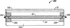
图4A为示出包含信号线的搁架的示例性实施例的透视图的示意图。4A is a schematic diagram illustrating a perspective view of an exemplary embodiment of a shelf containing signal wires.
图4B为示出示例性信号线结构的透视图的示意图。FIG. 4B is a schematic diagram illustrating a perspective view of an exemplary signal line structure.
图5为示出水平放置的包含多条信号线的搁架的示例性实施例的示意图,其中多条信号线寄生地连接到信号线。FIG. 5 is a schematic diagram illustrating an exemplary embodiment of a horizontally placed shelf including a plurality of signal lines parasitically connected to the signal lines.
图6为示出水平放置的包含多条信号线的搁架的示例性实施例的示意图,其中每一条信号线可以由RFID阅读器赋能。6 is a schematic diagram illustrating an exemplary embodiment of a horizontally positioned shelf containing multiple signal lines, each of which may be energized by an RFID reader.
图7为示出水平放置的包含多条具有变化长度的信号线的搁架的示例性实施例的示意图。FIG. 7 is a schematic diagram illustrating an exemplary embodiment of a horizontally positioned shelf containing a plurality of signal wires having varying lengths.
图8为示出垂直放置的包含多条信号线的搁架的示例性实施例的示意图,其中每一条信号线可以由RFID阅读器通电。8 is a schematic diagram illustrating an exemplary embodiment of a vertically positioned shelf containing multiple signal lines, each of which can be energized by an RFID reader.
图9示出替代方案中垂直放置的包含多条信号线的搁架的示例性实施例的示意图,其中一条信号线在搁架的整个宽度上延伸,而另一条信号线在小于搁架的整个宽度上延伸。9 shows a schematic diagram of an exemplary embodiment of a shelf containing multiple signal wires in an alternative arrangement vertically, where one signal wire extends across the entire width of the shelf and the other signal wire extends across less than the entire width of the shelf. Extended across the width.
图10为示出连接在一起的多个搁架的示例性实施例的示意图。Figure 10 is a schematic diagram illustrating an exemplary embodiment of multiple shelves connected together.
图11A为示出搁架的正面的示例性实施例的透视图。11A is a perspective view of an exemplary embodiment showing the front of the shelf.
图11B为示出搁架的背面的示例性实施例的透视图。11B is a perspective view showing an exemplary embodiment of the back of the shelf.
图12-14为示出由图4的信号线产生的实例电磁场的量级的曲线图。12-14 are graphs showing magnitudes of example electromagnetic fields produced by the signal lines of FIG. 4 .
具体实施方式Detailed ways
图1为示出用于文件和档案管理的实例射频识别(RFID)系统10的框图。尽管将办公场所转变成用电子版文档完全替代纸质文档的无纸环境曾引起了人们的一些兴趣,但很多行业仍然严重依赖于纸质文件。实例包括律师事务所、政府机构和用于存储业务、刑事和医疗记录的设施。这些文件可以位于多个“智能存储区”12,如,在图1所示的开放式搁架12A、柜12B、竖式文件隔板12C、智能小车12D、桌面阅读器12E、或类似位置上。FIG. 1 is a block diagram illustrating an example radio frequency identification (RFID)
这样,可以将智能存储区12设置在组织内部的多个位置,而不是在单个文件室中。例如,智能存储区12可以与特定位置相关,如备审案件搁架,并因此可以称为或认为是“专用”搁架。另如以下所述,智能存储区12可位于靠近(例如)医院或诊所、法律事务所、会计事务所、经纪行、或银行中的各个办公室或其他区域的位置,这样不论文件位于中央文件室,还是位于分散的地点,都能够加以跟踪。In this way, smart storage areas 12 can be located in multiple locations within an organization rather than in a single file room. For example, a smart storage area 12 may be associated with a particular location, such as a docket rack, and thus may be referred to or considered a "dedicated" rack. As also described below, the smart storage area 12 may be located near various offices or other areas in, for example, a hospital or clinic, law firm, accounting firm, brokerage firm, or bank so that no matter where the files are located in the central file room , or in dispersed locations, can be tracked.
本文所用的术语“智能存储区”一般指配备RFID询问能力以有助于跟踪和定位存储区内放置的物品的存储区。特别地,智能存储区12的RFID询问能力可以读取与储存在各自的存储区中的物品相关的RFID标签。换句话讲,RFID标签可以与关注的物品相关并可以应用于它们。标签甚至可以嵌入物品或物品的包装内,从而标签至少基本上是不易察觉的,这可以帮助防止被发现和篡改。因此,用RFID标签来“原始标记”物品是可能的,例如在物品的生产过程中就将RFID标签插入或帖附到物品中,就像文件夹、文档、书等。As used herein, the term "smart storage area" generally refers to a storage area equipped with RFID interrogation capabilities to facilitate tracking and locating items placed within the storage area. In particular, the RFID interrogation capabilities of the smart storage areas 12 can read RFID tags associated with items stored in the respective storage areas. In other words, RFID tags can be associated with and applied to items of interest. The tag can even be embedded within the item or packaging of the item so that the tag is at least substantially imperceptible, which can help prevent detection and tampering. Therefore, it is possible to "originally mark" items with RFID tags, for example inserting or attaching RFID tags to items during their production, like file folders, documents, books, etc.
多个制造厂商生产RFID标签或标记,包括Texas Instruments(Dallas Texas),命名为“Tag-it”的产品。RFID标签通常包括具有一定容量的存储器的集成电路,存储器的一部分可以用于将某些信息写到标签,另一部分可以用于将额外的信息存储到标签。集成电路可操作地连接到天线,天线以本领域熟知的方式从源接收RF能量并且也反向散射RF能量。在文件跟踪系统14内,就是这种反向散射的RF能量提供可以由询问器(通常称为阅读器)接收的信号,以获得关于RFID标签和标签相关的物品的信息。Several manufacturers produce RFID tags or tags, including Texas Instruments (Dallas Texas), a product named "Tag-it". RFID tags usually include an integrated circuit with a certain amount of memory, a part of which can be used to write certain information to the tag, and another part can be used to store additional information to the tag. The integrated circuit is operatively connected to an antenna that receives RF energy from a source and also backscatters RF energy in a manner well known in the art. Within
RFID系统10可以工作在电磁频谱的超高频(UHF)范围内,例如在900MHz和3.0GHz之间,这个范围经常用于工业、科技和医疗(ISM)应用中。然而,其他频率可以用于RFID应用,本发明并未受此限制。又如,RFID系统可以13.56MHz的较低频率操作,允许频率方差为+/-7kHz。
智能存储区12的RFID询问器或阅读器垫将信息传送到文件跟踪系统14,该系统(如在关系数据库管理系统(RDBMS)内)提供中央数据存储,以用于汇集位置信息。实例信息包括特定物品的位置信息或从RFID芯片读取的信息。例如,RFID系统10可以跟踪医学档案,并且信息可以包括病人标识、文件标识、状态、医生信息、病例信息等等。文件跟踪系统14可以联网或者说是连接到一台或多台计算机,从而多个位置的个人可以访问相对于这些物品的信息。RFID interrogators or reader pads of smart storage area 12 communicate the information to document tracking
收集和汇集的信息可以用于多个方面。例如,用户可以请求特定物品或一组物品的位置,例如文件或一套书。文件跟踪系统14可以从数据存储中检索文件位置信息,并向用户报告在存储区中的至少一个内的物品所处的最后位置。可任选地是,系统可以再获得或者说是再采集物品的当前位置以验证物品位于数据库中指示的位置。The information collected and aggregated can be used in a number of ways. For example, a user may request the location of a particular item or set of items, such as a file or a set of books.
又如,当物品被置于某个位置并且随时可用时,文件跟踪系统14可以通知用户。例如,可以通知律师文件可以随时待审并且刚被放置在其办公桌处。当然,文件跟踪系统14可用于审判室或法庭中存储的法律文档,并由法院工作人员(例如法官、书记员等等)使用。相似地,如果病人档案位于指定的区域,可以通知(可能通过移动电话或寻呼机,或通过电子邮件)医学专业人员该文档(可能是与文档有关的人)随时待审。As another example, the
文件位于某个位置等待进一步处理的事实可用由文件跟踪系统14来记录,以作为该物品位置历史的一部分。需要注意的是,某人希望处理的位于某个搁架或其他存储位置的某个文件,不同于存储室包含的需团体或组织内任何人(可能)等待处理的大量文件换句话说,具有用于某人的某个文件的某个搁架是专用于此人的,而收藏团体所有成员的所有文件的通用文件室并不专用于任何人。The fact that a document is in a location awaiting further processing can be recorded by the
另外,由RFID系统10搜集的信息可以用于跟踪(例如)处理中的周期、一人或多人利用这些文件工作的效率和处理的效率。如果信息是在软件系统内维护的,则这个信息也可提供位置档案的类型。Additionally, the information gathered by the
系统10的智能存储区12中的一些可以配备一个或多个信号线结构,该信号线结构为询问文件提供传播波导,(如)以有助于确定在存储区12中的每一处有哪些文件。例如,一个或多个信号线结构位于开放式搁架12A的搁架单元内,以产生电磁场,以用于与文件相关的RIFD标签进行通信。相似地,信号线结构可以位于柜12B、竖式文件隔板12C、智能小车12D、桌面阅读器12E等等内。可改进现有的搁架以包括信号线结构,或信号线结构可以构建到搁架中并且作为单元随搁架一起购买。又如,信号线结构可以构建到智能存储区12的机架或壳体(例如后面板)中。Some of the smart storage areas 12 of the
智能存储区12中的每一个可以包括信号线结构控制系统来为信号线结构中的信号线赋能,以询问或查询RFID标签。如果连续进行查询,信号线结构控制系统内的控制器可以包括电路,该电路用于通过信号线结构中的多路信号线顺序地多路传输信号。信号线结构控制系统可以使信号线以预定的次序询问智能存储区12的部分。信号线结构控制系统可以包括一个或多个控制节点,即操作以控制信号线子组的子控制器。与给定控制节点相关的信号线的数量、位置和其他特性可以由用户来确定。例如,如果需要快速查询搁架,可以将更多的控制节点添加到系统中。另一个方法是由用户来配置和定制信号线结构控制系统,从而控制节点或智能存储区12的部分以用户指定的顺序来查询。例如,如果在某些时间内智能存储区12的一个部分不可用,那么在这些时间内不需要询问该区域中的RFID标签。Each of the smart storage areas 12 may include a wire structure control system to energize the wires in the wire structure to interrogate or interrogate RFID tags. If interrogated sequentially, the controller within the signal line structure control system may include circuitry for sequentially multiplexing signals over multiple signal lines in the signal line structure. The signal line structure control system may cause the signal lines to interrogate portions of the smart memory area 12 in a predetermined order. The signal line structure control system may include one or more control nodes, ie, sub-controllers operative to control subsets of signal lines. The number, location and other characteristics of signal lines associated with a given control node can be determined by the user. For example, more control nodes can be added to the system if fast interrogation of racks is required. Another approach is for the user to configure and customize the signal line structure control system so that the control nodes or portions of the smart memory area 12 are queried in a user-specified order. For example, if a portion of the smart storage area 12 is unavailable during certain times, the RFID tags in that area need not be interrogated during those times.
正如本文详述,在信号线结构中,可以设计智能存储区12中的每一个内使用的信号线,以在存储区12内的“询问区域”内产生至少一定强度的电磁场。出于一种或多种原因,这可能是有利的,包括在给定智能存储区12的整个询问区域中提高文件检测的准确度。由信号线产生的磁场可以用于向与智能存储区12内的物品相关的标签通电,并且每一个标签中感应的能量通常与围绕信号线的电磁场的强度成正比。有利地是,可以利用信号线结构在整个询问时段内产生具有一定量级的场,该量级超出为RFID标签赋能的阈值量级。换句话讲,可以控制信号线结构以产生具有一定量级的电磁场,该量级满足或超出询问阈值(如,100-115dBuA/m),足以与距离信号线结构高达若干英寸的扩展RFID标签进行通信。因此,本文所述的方法可提高为与设置在存储区12内的物品相关的所有或基本上所有标签赋能的可能性,并且可成功检测物品。As detailed herein, in the signal line configuration, the signal lines used within each of the smart storage areas 12 can be designed to generate an electromagnetic field of at least some strength within the "interrogation zone" within the storage area 12 . This may be advantageous for one or more reasons, including increasing the accuracy of document detection throughout the interrogation area of a given smart storage area 12 . The magnetic fields generated by the signal wires can be used to energize tags associated with items within the smart storage area 12, and the energy induced in each tag is generally proportional to the strength of the electromagnetic field surrounding the signal wires. Advantageously, the signal line structure can be utilized to generate a field with a magnitude that exceeds a threshold magnitude for energizing an RFID tag throughout the interrogation period. In other words, the signal line structure can be manipulated to generate an electromagnetic field with a magnitude that meets or exceeds the interrogation threshold (e.g., 100-115dBuA/m), sufficient to communicate with an extended RFID tag up to several inches away from the signal line structure. to communicate. Accordingly, the methods described herein may increase the likelihood that all or substantially all tags associated with items disposed within storage area 12 will be enabled and the items will be successfully detected.
图2为示出图1的智能存储区12A的示例性实施例的框图。在此实例实施例中,智能存储区12A包括多个搁架16A-16C(统称为“搁架16”)。当然,在其它实施例中,智能存储区12A可以包含多于或少于三个搁架。在图2的实例中,智能存储区12A包含搁架16C,该搁架具有信号线结构的信号线17。信号线17可以通过电缆18电连接到RFID阅读器19。电缆18可以是能够往返RFID阅读器19传送信号的任何类型的电缆,例如标准的RG58同轴电缆。RFID阅读器19的一个实例是Sirit,Inc.(Toronto,Canada)出售的Sirit Infinity 510阅读器。包含RFID标签的书、文件夹、箱子或其他物品可以放置在搁架16C上。RFID阅读器19通过输出信号,经由电缆18为信号线17通电。被通电时,信号线17产生电磁场,如以下进一步详述。电磁场为位于搁架16C上的RFID标签通电。通电的RFID标签可以反向散射包含信息的RF信号,该信息由信号线17接收并且经由电缆18电传送到RFID阅读器19。例如,固定到位于搁架16C上的文件夹的RFID标签可以将RF信号反向散射到RFID阅读器19,从而确认RFID标签(并且对应地确认文件夹)位于搁架上。FIG. 2 is a block diagram illustrating an exemplary embodiment of the
在其他实施例中,搁架16中的每一个可以包含信号线结构的信号线17。在这类实施例中,每一个搁架16可以具有单独相关的RFID阅读器19。在另一个实施例中,智能存储区12A内的多个搁架16可以缆接在一起,以连到单个阅读器19。在这种实施例中,阅读器19可以接收确认,从而指示出包含RFID标签的文件夹位于智能存储区12A中的搁架16中的某一个上。In other embodiments, each of the shelves 16 may contain a
在另一个实施例中,多个智能存储区12可以相互连接。例如,可以使用电缆布线将智能存储区12A中的搁架16C与智能存储区12B中的搁架互连,其中智能存储区12B中的搁架基本上类似于搁架16C。在这类实施例中,单个阅读器19可以询问位于存储区12A和12B内的物品,以从与物品相关的标签读取信息,并且确定智能存储区12A或智能存储区12B内的特定文件夹的位置。尽管是相对于智能存储区12A和12B出于实例目的所述,但智能存储区12中的任何一个可以包括信号线结构的一条或多条信号线17,该信号线如本文所述用于询问智能存储区12内的物品。另外,已经对使用连接至一个或多个搁架16的一个或多个RFID阅读器19的实施例进行了描述。In another embodiment, multiple smart storage areas 12 may be interconnected. For example, cable routing may be used to interconnect
图3为示出信号线20相对于RFID标签22的实例取向的透视图,该标签与位于智能存储区12中的一个内的物品(未示出)相关。在多个RFID应用中,例如RFID系统10的智能存储区12,产生大电磁场21经常是有利的。在这种情况下,电磁场从信号线20以点划线所示的半圆柱形延伸,以形成询问区域24。特别地,电磁场21的量级满足或超出在询问区域24的相当大一部分上为标签22赋能所需的最小询问阈值,从而得到整个询问区域上的可靠通信。例如,信号线20可以产生能够在一定距离(D)上通过扩展该电磁场的近场元件与RFID标签22进行通信的电磁场,这个距离明显超过常规的结构所实现的距离(如,距离信号线20大约15mm(0.59英寸)或更小)。智能存储区12中的每一个可以利用能产生电磁场的信号线结构中的一条或多条信号线20,该电磁场满足或超出为整个智能存储区中的标签赋能的询问阈值。FIG. 3 is a perspective view showing an example orientation of signal wire 20 relative to
在本文所述的所有实例和示例性实施例中,与特定物品相关的RFID标签22可以是类似的,并且物品本身也可以是类似的。例如,与特定物品相关的RFID标签22在类型上可以类似于与置于信号线20上的物品相关的所有其他RFID标签22。于2007年9月27日提交的名称为“EXTENDED RFIDTAG(扩展的RFID标签)”、代理人卷号为63535US002/1004-311US01的共同待审的专利申请No._中描述了实例标签22,该专利的全文以引用的方式并入本文。In all of the examples and exemplary embodiments described herein, the RFID tags 22 associated with a particular item may be similar, as may the item itself. For example, an
图4A为更详细地示出图1的搁架16C的示例性实施例的透视图的示意图。搁架16C包括基底32,该基底可以由聚苯乙烯片材或其他类型的基底材料制成。信号线30可以固定到搁架16C的顶部表面104上,并且接地平面34(以虚线表示)可以固定到搁架16C的底部表面106上。可以使用其他技术设置信号线30和接地平面34。信号线30可以在每一个末端处连接到连接器26A和26B。在图4的实例中,所示的连接器26A和26B为SubMiniature version A(SMA)连接器,但也可以使用其他类型的连接器。接地平面部分28A和28B是接地平面34的组成部分,这些部分已在周围被缠绕以延伸到搁架16C的顶部表面104。作为一个实例,信号线30和接地平面34可以由铜带构成。在一个实例实施例中,接地平面34的宽度可以是信号线30的宽度的至少两倍。在另一个实例实施例中,接地平面34的宽度可以是信号线30的宽度的至少三倍。在另一个实例实施例中,接地平面34的宽度可以是信号线30的宽度的至少四倍。如下图所示,接地平面34的宽度相对于信号线30的宽度影响搁架16C的信号线结构的读取范围。FIG. 4A is a schematic diagram showing a perspective view of an exemplary embodiment of
RFID阅读器19(图2)通过电缆18连接到连接器26A。为了避免在RFID阅读器19和连接器26A之间的阻抗误匹配,使用匹配结构来将电源从RFID阅读器19有效地连接到信号线30并减少连接器26A处的反射。在仅使用一个搁架16C的实施例中,可以将负载连接到连接器26B以用于合适的终端连接。作为一个实例,可以使用2瓦特、50Ω的负载。RFID reader 19 (FIG. 2) is connected by
图4B为具有示例性信号线结构36的搁架的透视图的示意图。信号线结构36包括至少一条信号线30、接地平面34,并且在一些实施例中包括负载35。信号线30和接地平面34可以由基底32隔开。在其他实施例中,信号线结构36可以包括基本上类似于信号线30的多条信号线。包含RFID标签22的文件夹33可以置于信号线30上。本文所述的实施例是指信号线,但本领域的技术人员将认识到信号线是信号线结构的一部分。FIG. 4B is a schematic illustration of a perspective view of a shelf with an exemplary
在搁架16C上放置包含RFID标签的相对大量物品的情况下,确定搁架16C上关注的特定物品位于如搁架16C的左侧、右侧、或中间可能是有用的。出于实例的目的,对沿着搁架的长度利用信号线结构提供侧向搁架位置(即边对边位置或纵向位置)的至少两个选项进行了描述。In situations where a relatively large number of items containing RFID tags are placed on
第一个选项是在整个信号线30上的多个已知点动态地改变电负载。RFID阅读器19可以产生控制逻辑以驱动(例如)开关等,以选择置于整个信号线30上的多个位置处的端接负载。改变整个信号线30上的多个已知点处的负载有效地改变信号线30的电气长度,因为负载可以端接来自RFID阅读器19的信号。在这种实施例中,通过开关等连接的电负载可以置于信号线30上的已知位置处。RFID阅读器19可以为信号线30通电,但由于该负载由RFID阅读器19来选择,信号线30的电气长度可以仅从连接器26A沿着信号线30延伸到负载。根据接收自置于搁架16C上的物品上的RFID标签22的反向散射RF信号,RFID阅读器19可以确定是否从关注的特定物品接收到响应。如果是这样,RFID阅读器19确定关注的物品位于连接器26A和负载位置之间。如果关注的特定物品并不位于负载之前,RFID阅读器19可以选择信号线30上不同位置上的第二负载,并且RFID阅读器19可以再次检测以查看关注的特定物品是否位于负载之前。此过程可以重复进行,直到发现关注的特定物品。这样,可以确定关注的特定物品的相对位置是在所选负载的当前位置和此前所选负载的位置之间。这个过程对于很长的或具有包含RFID标签的大量物品的搁架16C是尤其可用的。知道关注的特定物品的相对位置可以允许更快地确定物品在搁架上的位置。在另一个实施例中,可以将负载置于已知的位置处,并且如果关注的特定物品位于负载之前,RFID阅读器19可以选择信号线30上的不同位置上的另一个负载。RFID阅读器19可以再次检测以查看关注的特定物品是否位于负载之前。此过程可以重复进行,直到关注的特定物品不再位于负载之前。这样,可以确定关注的特定物品的相对位置是在所选负载的当前位置和此前所选负载的位置之间。A first option is to dynamically vary the electrical load at known points throughout the
第二个提供侧向搁架位置能力的选项是从已知宽度的基底32中的一系列不同的电介质材料构造信号线30,从而限定沿着搁架16C的基底32的已知位置区域。例如,使用具有较低介电常数的电介质材料来较靠近RFID阅读器19。沿着信号线30有效地使用不同电介质材料导致信号线产生具有包络的电磁场,该包络在远离阅读器19的方向从右至左衰减。即,较靠近阅读器19的具有较高介电常数的信号线30的部分将产生比由具有较高介电常数的材料形成的信号线30的部分的具有较低量级的电磁场的一部分。来自RFID阅读器19的功率可以顺序地增长,从而沿着信号线30的每一个位置区域中的电磁场量级顺序地通过询问阈值。这个过程可一直持续到关注的特定设备上的RFID标签被检测到,即,被赋能并将RF信号反向散射到RFID阅读器19。A second option to provide lateral shelf location capability is to construct
例如,假设关注的特定物品位于搁架上16C上靠近信号线30的末端的位置处,靠近连接器26B。还假设不同的电介质材料出现在基底32内对应于信号线30的第一部分、第二部分、和最后部分的区段处。最初,来自RFID阅读器19的功率可能低,从而只有信号线30的第一部分能够产生电磁场,该电磁场的强度大于阈值强度,以实现与位于该部分中的标签进行RF通信。由于关注的特定设备位于信号线30的最后部分中,对供电作出响应的由RFID阅读器19接收的任何反向散射RF信号不会包含关注的特定物品相关的信息。然后,可以增加RFID阅读器19的功率,使得所得的用于RF通信的至少足够强度的电磁场上延至信号线30的第二部分并覆盖该部分。对供电作出响应的RFID阅读器19再次接收的反向散射RF信号不会包含关注的特定物品相关的信息。最后,可以再次增加RFID阅读器19的功率,使得所得的足够强度的电磁场延伸至信号线30的末端。在此情况下,对供电作出响应的由RFID阅读器19接收的反向散射RF信号将包括来自与关注的特定物品相关的RFID标签的RF信号。因此,将知道关注的特定物品的相对位置位于搁架16C的最后部分中。For example, assume that a particular item of interest is located on
在其他实施例中,来自RFID阅读器19的功率可以缓降,即降低。在这种实施例中,RFID阅读器19首先确定来自关注的特定物品的响应是否被接收,然后缓降功率直到再也检测不到关注的特定物品。此外,可以组合这些以及其他方法以提高定位的准确度。将信号线30划分成三部分只是说明性的;如果必要的话,可以将信号线30划分成较多或较少的部分。In other embodiments, the power from the
包含RFID标签22的物品33(例如文件夹)一般可以侧向模式置于智能存储区(如图2的搁架16C)上。然而,在一些情况下,具有RFID标签22的物品(例如文件或箱子)可以从后到前地放置。如果在搁架16C上从后到前地放置包含RFID标签22的物品,则单条信号线17(图2)可能无法产生足够强的电磁场来为所有物品上的RFID标签22通电。例如,置于搁架40最前部或最后部的物品的RFID标签22可能位于距单条居中的信号线17一定距离的位置处,该距离大于由信号线17产生的电磁场的范围。由于物品上RFID标签22的放置,或如果搁架16C极其宽,就可以出现这种情况。Items 33 (eg, file folders) containing RFID tags 22 may generally be placed in a sideways mode on a smart storage area (eg,
图5为示出搁架40的示例性实施例的俯视图的示意图。设计搁架40,从而在搁架40内得到增大的读取范围深度(即,从搁架的前部到后部),以解决上述问题。如图5所示,搁架40包含多条寄生信号线44A-44D(统称为信号线44)、以及连接到至少一个RFID阅读器19的至少一条通电的信号线42。尽管未示出,可以通过连接到地面的负载来端接通电的信号线42。实际上,寄生信号线44的使用增加了由功率信号线42产生的电磁场的深度范围,而不需要任何额外的阅读器和/或端口。FIG. 5 is a schematic diagram illustrating a top view of an exemplary embodiment of a
功率信号线42可以由RFID阅读器19通电。由功率信号线42产生的电磁场以电磁的方式与寄生信号线44中的一条或多条连接以激励寄生信号线。换句话讲,功率信号线42所产生的电磁场可以在寄生信号线44中的每一条中感应寄生电流,该寄生电流又在寄生信号线中的每一个周围产生局部电磁场。这样,与物品相关的RFID标签22可以由寄生信号线44和/或功率信号线42中的任意一个或其组合来通电,并且关注的特定物品的反向散射RF信号可以由RFID阅读器19来识别。例如,置于搁架40后部处的具有RFID标签22的物品可以由寄生信号线44D产生的电磁场通电,而置于搁架40前部处的具有RFID标签22的物品可以由寄生信号线44A产生的电磁场通电。在多种实施例中,可以使用较多或较少的寄生信号线44。在多种实施例中,也可以改变功率信号线42的位置。
图6为示出搁架36的另一个示例性实施例的俯视图的示意图。当具有RFID标签22的物品从后到前地置于搁架36上时,可能有利的是根据搁架深度来辨识物品的位置,如除了物品是否位于靠近搁架36的左部、右部或中部之外,物品是否还位于靠近搁架36的后部、中部或前部。对相对于搁架的长度和深度来辨识搁架上的物品的位置的技术有所描述。尽管出于方便和简洁的目的,本文使用了术语“前”、“中”、“后”、“右”和“左”,但所述技术可以用于确定关注的特定物品的更精确位置。FIG. 6 is a schematic diagram illustrating a top view of another exemplary embodiment of a
在此实例中,搁架36包含沿着搁架36的长度纵向延伸的多条信号线38A-38D(统称为信号线38)。在多种实施例中,可以使用较多或较少的信号线38。尽管未示出,但可以通过连接到地面的负载来端接信号线38。包含RFID标签22的物品可以在搁架36上从后到前地放置。如图6所示,信号线38A-38D在整个搁架的宽度上大致等距离地间隔开,并且可以选择性地赋能以确定搁架上所放物品的深度位置(即,本文的深度位置也称为从前到后的位置)。在图6的实施例中,可以利用一个或多个RFID阅读器19顺序地为信号线38中的每一条通电。对信号线38中的一条通电可以导致未被通电的剩下的信号线38在给定的时间寄生地激励通电的信号线产生的电磁场。然而,在一些实施例中,可以通过本领域熟知的方法来抑制未通电的信号线38产生谐振。例如,可以选择地电切换未通电的信号线38以直接连接到接地平面。In this example,
在为信号线38中的一条或多条通电的实施例中,包含RFID标签22的关注的特定物品可以通过信号线38中的一条或多条将RF信号反向散射到一个或多个RFID阅读器19。包含RFID标签22的关注的特定物品的深度位置(如,搁架36的前部、中部或后部)可根据信号线38中的哪一条已经向RFID阅读器19反向散射了RF信号来确定。例如,假设关注的特定物品位于搁架36的右后角。那么,可以为信号线38顺序地通电。可以首先为信号线38A通电,同时抑制信号线38B-38D产生寄生励磁。因为RFID标签22可能超出信号线38A所产生的电磁场的范围,所以关注的特定物品可以不反向散射RFID信号。此过程可以重复进行,直到连接到信号线38D的RFID阅读器19为信号线38D通电。当信号线38D被通电并且剩下的信号线38被抑制产生谐振时,RFID标签22可以从由信号线38D产生的电磁场接收功率并将RF信号经由信号线38D反向散射到RFID阅读器19。如果经由多条信号线38从关注的特定物品接收了响应,那么阅读器19可以使用与每一个响应相关的信号强度以辨识物品的正确深度位置。例如,反向散射最强RF信号的信号线可以用于确定物品的深度位置。或者,如果通过一组信号线38接收了响应,那么阅读器19可以通过辨识设置在该组中部内的信号线(如,从接收响应的三条相邻的信号线中选择中间的信号线)来确定关注的物品的深度位置。这样,可将关注的特定物品的位置确定为位于搁架36的后部中。另外,通过应用上述相对于图4的技术,也可以确定关注的特定物品的侧向位置。In embodiments where one or more of the signal lines 38 are energized, the particular item of interest containing the
上述技术以顺序的方式描述为信号线38通电。然而,也可以使用其他技术。在一个实施例中,可以利用不同的RFID阅读器19为信号线38中的每一条通电。在另一个实施例中,可以使用递归法仅为信号线38的第一子组通电,然后确定关注的特定物品是否已反向散射RF信号。如果某个关注的物品已经反向散射了RF信号,那么只有信号线38的第一子组的次级子组可以被通电,并且重复此过程,直到可确定关注的特定物品的深度位置。当信号线38的第一子组被通电时,如果关注的特定物品没有反向散射RF信号,那么给信号线38的第二子组通电以检测关注的特定物品是否反向散射了RF信号。此过程重复进行,直到可确定关注的特定物品的深度位置。在其他实施例中,可以采用多种其他顺序为信号线38通电。The techniques described above described energizing signal line 38 in a sequential fashion. However, other techniques may also be used. In one embodiment, a
图7为示出搁架46的另一个示例性实施例的俯视图的示意图。在此实例中,搁架46包含长度变化的多条信号线48A-48F(统称为信号线48)。在多种实施例中,可以使用较多或较少的信号线48,并且它们各自的长度可以不同于图7所示的示例性实施例。尽管未示出,但可以通过接地的负载来端接信号线48。在图7的实施例中,搁架46可以用于辨识搁架46上关注的特定物品的侧向位置。在置于搁架46上的物品尺寸类似的情况下,图7的实施例可以是尤其可用的。可以通过RFID阅读器19首先为具有最短长度的信号线(信号线48F)通电,同时可以抑制剩下的信号线48产生谐振。如果关注的特定物品的RFID标签22将RF信号反向散射到RFID阅读器19,就知道了关注的特定物品的位置是在沿着信号线48F的长度位于搁架46上侧向位置处。如果关注的特定物品没有将RF信号反向散射到RFID阅读器19,那么具有下一个最短长度的信号线(信号线48E)可以由RFID阅读器19通电,同时阻止剩余的信号线48产生谐振。如果关注的特定物品将RF信号反向散射到RFID阅读器19,那么就知道了关注的特定物品的位置是在信号线48F的末端和信号线48E的末端之间的搁架46上的侧向位置处。重复这个过程,直到与关注的特定物品相关的RFID标签22将RF信号返回到RFID阅读器19。这样,在发现了关注的特定物品后,可将关注的物品的位置确定为位于通电的信号线的末端和此前通电的信号线之间。FIG. 7 is a schematic diagram illustrating a top view of another exemplary embodiment of a
在另一个实施例中,可以通过一个或多个RFID阅读器19为所有信号线48通电。与关注的特定物品相关的RFID标签22可以将RF信号反向散射到RFID阅读器19。根据哪一条信号线48向RFID阅读器19传送了反向散射的RF信号,可确定沿着搁架46的关注的特定物品的侧向位置。In another embodiment, all signal lines 48 may be powered by one or
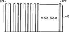
图8为示出搁架60的另一个示例性实施例的俯视图的示意图。搁架60包含在整个搁架60的宽度上(即从前到后)延伸的多条信号线62A-62N(统称为信号线62)。如图8所示,信号线62A-62N沿着搁架的长度大致侧向等距离地间隔开并且可被选择地赋能以确定置于搁架上的物品的纵向位置(即,侧向位置在本文也称为边到边位置)。FIG. 8 is a schematic diagram illustrating a top view of another exemplary embodiment of a
尽管未示出,但可以通过连接到提供接地平面的电导体的负载来端接信号线62。在图8的实施例中,可以确定关注的特定物品的沿着搁架60的侧向位置。在多种实施例中,可以使用较多或较少的信号线62。可以在搁架60上边到边地放置具有RFID标签22的物品。在这种实施例中,可以通过至少一个RFID阅读器19顺序地为信号线62中的每一条通电。对信号线62中的一条进行通电可以使得在给定的时间未被通电的剩余的信号线62寄生地激励由通电的信号线产生的磁场。然而,在一些实施例中,通过本领域熟知的技术可以抑制未通电的信号线62产生励磁。Although not shown, signal line 62 may be terminated by a load connected to an electrical conductor that provides a ground plane. In the embodiment of FIG. 8, the lateral position along
在为信号线62中的一条或多条通电的实施例中,包含RFID标签22的关注的特定物品可以通过信号线62中的一条或多条将RF信号反向散射到一个或多个RFID阅读器19。包含RFID标签22的关注的特定物品的沿着搁架60的位置可根据信号线62中的哪一条向RFID阅读器19传送了反向散射的RF信号来确定。例如,假设关注的特定物品位于搁架60的右端。那么,可以顺序地为信号线62通电。可以首先为信号线62A通电,同时抑制信号线62B至62N产生寄生励磁。与关注的特定物品相关的RFID标签22可以不反向散射RF信号,因为RFID标签22可以超出信号线62A产生的电磁场的范围。此过程可以重复进行,直到连接到信号线62N的RFID阅读器为信号线62N通电。当为信号线62N通电,并且抑制剩余的信号线62产生谐振时,RFID标签22可以从由信号线38D产生的电磁场接收功率并经由信号线62N将RF信号反向散射到阅读器19。与图6的描述类似,如果多条信号线62反向散射RF信号,那么阅读器19可以使用与反向散射RF信号的信号线62中的每一条相关的信号强度来确定侧向位置,或者选择反向散射RF信号的信号线62组中的中部。这样,将知道关注的特定物品的位置是在搁架60的右端。In embodiments where one or more of the signal lines 62 are energized, the particular item of interest containing the
上述技术描述以顺序的方式为信号线62通电。然而,也可以使用其他技术。在一个实施例中,可以利用不同的RFID阅读器19为信号线62中的每一条通电。在另一个实施例中,可以使用递归法仅为信号线62的第一子组通电,然后确定是否关注的特定物品已反向散射RF信号。如果关注的特定物品已经反向散射了RF信号,那么只有信号线62的第一子组的次级子组可以被通电,并且重复此过程,直到可以确定关注的特定物品的侧向位置。当信号线62的第一子组被通电时,如果关注的特定物品没有反向散射RF信号,那么为信号线62的第二子组通电以检测关注的特定物品是否反向散射了RF信号。此过程重复进行,直到可确定关注的特定物品的侧向位置。在其他实施例中,可以采用多种其他顺序为信号线62通电。The above technique describes energizing signal lines 62 in a sequential manner. However, other techniques may also be used. In one embodiment, a
图9示出搁架64的另一个示例性实施例的俯视图的示意图。搁架64包括沿着搁架64的宽度纵向延伸的多条信号线66A-66N(统称为信号线66)。搁架64还包括沿着小于搁架64的整个宽度纵向延伸的多条信号线68A-68N(统称为信号线68)。尽管未示出,可以通过接地负载来端接信号线66和68。如图9的实例所示,多条信号线66和68以交替方式在搁架64的整个宽度上布线。在一个实施例中,信号线68的长度是信号线66长度的一半。在图9的实施例中,可确定具有RFID标签22的关注的特定物品的侧向位置和从前到后的位置。可以通过RFID阅读器19顺序地为信号线66和68通电。例如,可以首先为信号线66A和信号线68A通电,然后为信号线66B和信号线68B通电。通电的信号线66和68中的一条可以从关注的特定设备的RFID标签22接收反向散射的RF信号。关注的物品沿着搁架64的长度的侧向位置可以根据哪一对信号线66和68从关注的特定物品传送了反向散射RF信号来确定。一旦确定了沿着搁架64的长度的位置,就可以切断到通电的信号线66中的一条的电源,并且保持信号线68中的一条的电源接通,来确定沿着搁架64的宽度(即,深度)的位置。如果关注的特定物品的RFID标签22反向散射RF信号,那么可以将关注的特定物品的位置辨识为位于搁架64的前部内。如果关注的特定物品没有反向散射RF信号,那么可以将关注的特定物品的位置辨识为位于搁架64的后部内。与图6和图8的描述类似,如果多条信号线66和68反向散射RF信号,那么阅读器19可以使用与反向散射RF信号的信号线66和68中的每一条相关的信号强度来确定位置,或者选择反向散射RF信号的信号线66和68组中的中部。FIG. 9 shows a schematic diagram of a top view of another exemplary embodiment of a
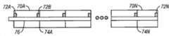
图10为物理地和电气地连接在一起以形成较大存储区的多个搁架70A-70N(统称为搁架70)的示意性实施例的侧视图的示意图。例如,在大的储存室中,可以将多个搁架70连接在一起,因为要存储的带有RFID标签22的物品的数量比搁架70中的一个的长度上适合的数量大。10 is a schematic diagram of a side view of an illustrative embodiment of a plurality of
可以通过连接器74A-74N(统称为连接器74)物理地和/或电气地将搁架70连接在一起。搁架70中的每一个可以包含置于搁架70末端处的RFID基准标签72A-72N(统称为RFID基准标签72)。RFID基准标签72也可以置于搁架70的其他位置中。The
为找到在搁架70中的一个中的关注的特定物品,可以将RFID阅读器19连接到搁架70A。搁架70N可以由负载端接到地。RFID阅读器19可以为在所有整个搁架70上延伸的信号线76通电。信号线76可以由多条较短的信号线组成,这些短信号线由连接器74物理地和/或电气地连接在一起。即,连接器74可以将搁架70连在一起,并且也可以将搁架70中的一个的信号线连接至一个相邻的搁架70的另一条信号线。在图10的实施例中,当根据关注的特定物品相关的RFID标签22寻找关注的特定物品时,RFID阅读器19可以为整个信号线76通电。阅读器19采用反向散射RF信号的形式从信号线76上的每个RFID标签22和RFID基准标签72接收响应。RFID阅读器19可以采用顺序方式接收反向散射的信号,使得RFID阅读器19首先从与搁架70中的一个相关的RFID基准标签72接收反向散射RF信号,然后从与置于搁架70上的物品相关的所有RFID标签22接收反向散射RF信号,再然后从与下一个搁架相关的RFID标签接收反向散射RF信号。通过筛选顺序反向散射数据和定位关注的特定物品,并确定哪些基准标签72位于与关注的特定物品相关的RFID标签22之前和之后,可以确定包含关注的特定物品的搁架70。例如,假设关注的特定物品位于搁架70D上,RFID阅读器19可以从RFDI基准标签70D、然后从与关注的物品相关的RFID标签、再从RFID基准标签70E接收反向散射RF信号。这样,可确定包含关注的特定物品的正确搁架是搁架70D。To locate a particular item of interest in one of the
一旦确定了正确的搁架70D,就可以通过RFID阅读器19传送静态命令将搁架上所有关注的物品设置为“静止”状态,如本领域所知的那样。特别地,将所有的标签都置于静止状态,不同的是:(1)关注的物品的RFID标签,和(2)已辨识搁架的RFID基准标签72和任选地后续搁架的RFID基准标签72。因此,对RFID阅读器19的后续检查作出响应的唯一RFID标签22将是与包含关注的特定物品的特定搁架相关的RFID标签72和与关注的特定物品相关的RFID标签22中的一个。Once the correct shelf 70D has been identified, a static command can be transmitted through the
然后,RFID阅读器19可以使用来自RFID基准标签72和与关注的特定物品相关的RFID标签22中的一个的定时响应来确定关注的特定物品的相对侧向位置。在一个实施例中,RFID阅读器可以确定与包含关注的特定物品的特定搁架70相关的RFID基准标签72的响应时间和与后续搁架70相关的RFID基准标签72的响应时间。RFID阅读器19也可以确定与关注的特定物品相关的RFID标签22的响应时间。根据这三个值,RFID阅读器19可以确定关注的特定物品的侧向位置。例如,再次假设关注的特定物品位于搁架70D上,RFID阅读器19可以确定RFID基准标签72D的响应时间是10秒,RFID基准标签72E的响应时间是11秒。RFID阅读器19可以确定与关注的特定物品相关的RFID标签22的响应时间是10.5秒。这样,RFID标签19可以确定关注的特定物品位于搁架70D上大约中途的位置。在另一个实施例中,RFID阅读器19可以具有RFID基准标签72的时间响应的预定表。在这类实施例中,RFID阅读器19可以只确定关注的特定物品的时间响应。可根据时间响应和包含RFID基准标签72的时间响应的表来确定关注的特定物品的侧向位置。
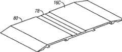
图11A和图11B为分别示出搁架16C的示例性实施例的俯视图和仰视图的透视图。搁架16C可以具有一体化组件,该组件包括具有顶部表面和底部表面的挤出型天线基底。图11A示出搁架16C的信号线78和顶部表面80。信号线78可以凹陷在顶部表面80内。图11B示出搁架16C的接地平面82和底部表面84。作为一个实例,接地平面82可以是信号线78的长度的三倍。11A and 11B are perspective views illustrating top and bottom views, respectively, of an exemplary embodiment of a
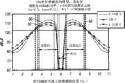
图12为示出表示示例性电磁功率电平的建模结果的图,该功率电平可望由信号线30的整个长度上的示例性搁架16C产生(图4),并在搁架16C上方的不同距离处测量的。图12所示的建模结果是假设以下条件时计算得出:基底32由250密耳(6.35mm)的聚苯乙烯构成,信号线30的宽度为1英寸(25.4mm)、长度为11英寸(279.4mm),接地平面34的宽度为4英寸(101.6mm)、长度为11英寸(279.4mm)。搁架16C上的信号线30可以在信号线30的不同位置处产生不同功率电平的电磁场。12 is a graph showing modeling results representing exemplary electromagnetic power levels that are expected to be generated by
例如,在搁架16C的1英寸(25.4mm)和3.5英寸(88.9mm)的剖视位置之间,在信号线30(86)上方0.75英寸(19mm)的距离处,电磁功率从约80dBμV增加到100dBμV以上。然后,在搁架16C的3.5英寸(88.9mm)和5.8英寸(147.3mm)的剖视位置之间,电磁功率在约4.8英寸(121.9mm)的剖视位置处增加到约113dBμV的最大值,然后开始下降直到在约5.8英寸(147.3mm)的剖视位置处电磁功率接近60dBμV。在搁架16C的5.8英寸(147.3mm)和6.2英寸(157.5mm)的剖视位置之间,电磁功率保持小于60dBμV。在6.2英寸(157.5mm)和约6.5英寸(165.1mm)的剖视位置之间,电磁功率增加到100dBμV以上。在6.5英寸(165.1mm)和约8.5英寸(215.9mm)的剖视位置之间,电磁功率在约7.5英寸(190.5mm)的剖视位置处增加到约113dBμV的最大值,然后下降,直到在11英寸(279.4mm)的剖视位置处电磁功率为约80dBμV。For example, between the 1 inch (25.4 mm) and 3.5 inch (88.9 mm) cross-sectional positions of
在信号线30(88)上方1英寸(25.4mm)的距离处,在搁架16C的1英寸(25.4mm)和3.5英寸(88.9mm)的剖视位置之间,电磁功率从约80dBμV增加到100dBμV以上。然后,在搁架16C的3.5英寸(88.9mm)和5.8英寸(147.3mm)的剖视位置之间,电磁功率在约4.8英寸(121.9mm)的剖视位置处增加到约112dBμV的最大值,然后开始下降,直到在约5.8英寸(147.3mm)的剖视位置处电磁功率接近60dBμV。在搁架16C的5.8英寸(147.3mm)和6.2英寸(157.5mm)的剖视位置之间,电磁功率保持小于60dBμV。在搁架16C的6.2英寸(157.5mm)和约6.5英寸(165.1mm)的剖视位置之间,电磁功率增加到100dBμV以上。在搁架16C的6.5英寸(165.1mm)和约8.5英寸(215.9mm)的剖视位置之间,电磁功率在约7.5英寸(190.5mm)的剖视位置处增加到约112dBμV的最大值,然后下降,直到在11英寸(279.4mm)的剖视位置处功率约为80dBμV。At a distance of 1 inch (25.4 mm) above signal line 30 (88), the electromagnetic power increases from about 80 dBμV to Above 100dBμV. Then, between the 3.5 inch (88.9 mm) and 5.8 inch (147.3 mm) sectional position of
在信号线30(90)上方1.25英寸(31.7mm)的距离处,在搁架16C的1英寸(25.4mm)和3.5英寸(88.9mm)的剖视位置之间,电磁功率从约80dBμV增加到100dBμV以上。然后,在搁架16C的3.5英寸(88.9mm)和5.8英寸(147.3mm)的剖视位置之间,电磁功率在约4.8英寸(121.9mm)的剖视位置处增加到约108dBμV的最大值,然后开始下降,直到在约5.8英寸(147.3mm)的剖视位置处电磁功率接近60dBμV。在5.8英寸(147.3mm)和6.2英寸(157.5mm)的剖视位置之间,电磁功率保持小于60dBμV。在6.2英寸(157.5mm)和约6.5英寸(165.1mm)的剖视位置之间,电磁功率增加到100dBμV以上。在6.5英寸(165.1mm)和约8.5英寸(215.9mm)的剖视位置之间,电磁功率在约7.5英寸(190.5mm)的剖视位置处增加到约108dBμV的最大值,然后下降,直到在11英寸(279.4mm)处电磁功率为约80dBμV。At a distance of 1.25 inches (31.7 mm) above signal line 30 (90), the electromagnetic power increases from about 80 dBμV to Above 100dBμV. Then, between the 3.5 inches (88.9 mm) and 5.8 inches (147.3 mm) of the
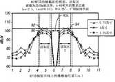
图13为示出示例性电磁功率电平的曲线图,该功率电平是由示例性搁架16C(图4)的第二实施例在信号线30的整个长度上产生,并在搁架16C上方的不同距离处测量的。图12所示的建模结果是假设以下条件时计算得出:使用由60密耳(1.52mm)的聚苯乙烯组成的基底32,信号线30的宽度为0.25英寸(6.35mm)、长度为11英寸(279.4mm),接地平面34的宽度为4英寸(101.6mm)、长度为11英寸(279.4mm)。FIG. 13 is a graph showing exemplary electromagnetic power levels generated by the second embodiment of
搁架16C上的信号线30可以在信号线30的不同位置处产生不同功率电平的电磁场。例如,在搁架16C的1英寸(25.4mm)和4英寸(101.6mm)的剖视位置之间,在信号线30(92)上方0.75英寸(19mm)的距离处,电磁功率从约75dBμV增加到稍低于100dBμV。然后在4英寸(101.6mm)和5.8英寸(147.3mm)的剖视位置之间,电磁功率在约5英寸(127mm)的剖视位置处增加到约102dBμV的最大值,然后开始下降,直到在约5.8英寸(147.3mm)的剖视位置处电磁功率接近60dBμV。在5.8英寸(147.3mm)和6.2英寸(157.5mm)的剖视位置之间,电磁功率保持小于60dBμV。在6.2英寸(157.5mm)和6.5英寸(165.1mm)的剖视位置之间,电磁功率增加到稍低于100dBμV。在6.5英寸(165.1mm)和约8英寸(203.2mm)的剖视位置之间,电磁功率在约7.5英寸(190.5mm)的剖视位置处增加到约102dBμV的最大值,然后下降,直到在11英寸(279.4mm)的剖视位置处电磁功率为约75dBμV。The
在信号线30(94)上方1英寸(25.4mm)的距离处,在搁架16C的1英寸(25.4mm)和4英寸(101.6mm)的剖视位置之间,电磁功率从约74dBμV增加到稍低于100dBμV。然后,在4英寸(101.6mm)和5.8英寸(147.3mm)的剖视位置之间,电磁功率在约5英寸(127mm)的剖视位置处增加到约100dBμV的最大值,然后开始下降,直到在约5.8英寸(147.3mm)的剖视位置处电磁功率接近60dBμV。在5.8英寸(147.3mm)和6.2英寸(157.5mm)的剖视位置之间,电磁功率保持小于60dBμV。在6.2英寸(157.5mm)和约6.5英寸(165.1mm)的剖视位置之间,电磁功率增加到稍低于100dBμV。在6.5英寸(165.1mm)和约8英寸(203.2mm)的剖视位置之间,电磁功率在约7.5英寸(190.5mm)的剖视位置处增加到约102dBμV的最大值,然后下降,直到在11英寸(279.4mm)的剖视位置处电磁功率为约80dBμV。At a distance of 1 inch (25.4 mm) above signal line 30 (94), the electromagnetic power increases from about 74 dBμV to Slightly below 100dBμV. Then, between the 4 inches (101.6 mm) and 5.8 inches (147.3 mm) of the sectional position, the electromagnetic power increases to a maximum of about 100 dBμV at about 5 inches (127 mm) of the sectional position and then begins to decrease until The electromagnetic power is close to 60 dBμV at the cross-sectional location of about 5.8 inches (147.3 mm). Electromagnetic power remains less than 60 dBμV between the 5.8 inch (147.3 mm) and 6.2 inch (157.5 mm) cross-sectional positions. Between the 6.2 inches (157.5 mm) and approximately 6.5 inches (165.1 mm) cross-sectional positions, the electromagnetic power increases to slightly less than 100 dBμV. Between the 6.5 inches (165.1mm) and about 8 inches (203.2mm) of the cutaway position, the electromagnetic power increases to a maximum of about 102dBμV at about 7.5 inches (190.5mm) of the cutaway location and then decreases until at 11 The electromagnetic power is about 80 dBμV at the position of the cross-section in inches (279.4 mm).
在信号线30(96)上方1.25英寸的距离处,在1英寸(25.4mm)和4英寸(101.6mm)的剖视位置之间,电磁功率从约70dBμV增加到约95dBμV。然后,在4英寸(101.6mm)和5.8英寸(147.3mm)的剖视位置之间,电磁功率在约4.8英寸(121.2mm)的剖视位置处增加到约97dBμV的最大值,然后开始下降,直到在约5.8英寸(147.3mm)的剖视位置处电磁功率接近60dBμV。在5.8英寸(147.3mm)和6.2英寸(157.5mm)的剖视位置之间,电磁功率保持小于60dBμV。在6.2英寸(157.5mm)和约6.5英寸(165.1mm)的剖视位置之间,电磁功率增加到约95dBμV。在6.5英寸(165.1mm)和约8英寸(203.2mm)的剖视位置之间,电磁功率在约7.5英寸(190.5mm)的剖视位置处增加到约97dBμV的最大值,然后下降,直到在11英寸(279.4mm)的剖视位置处电磁功率为约80dBμV。At a distance of 1.25 inches above signal line 30 (96), the electromagnetic power increases from about 70 dBuV to about 95 dBuV between the 1 inch (25.4 mm) and 4 inch (101.6 mm) cutaway positions. Then, between the 4" (101.6mm) and 5.8" (147.3mm) sectional locations, the electromagnetic power increases to a maximum of about 97dBμV at about 4.8" (121.2mm) sectional locations and then begins to decrease, Until the electromagnetic power approaches 60dBμV at a cutaway location of about 5.8 inches (147.3mm). Electromagnetic power remains less than 60 dBμV between the 5.8 inch (147.3 mm) and 6.2 inch (157.5 mm) cross-sectional positions. Between the 6.2 inches (157.5 mm) and about 6.5 inches (165.1 mm) cross-sectional positions, the electromagnetic power increases to about 95 dBμV. Between the 6.5 inches (165.1 mm) and about 8 inches (203.2 mm) of the sectional position, the electromagnetic power increases to a maximum of about 97 dBμV at about 7.5 inches (190.5 mm) of the sectional position and then decreases until at 11 The electromagnetic power is about 80 dBμV at the position of the cross-section in inches (279.4 mm).
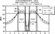
图14为示出示例性搁架16C(图4)的第三实施例产生的示例性电磁功率电平的曲线图。图14所示的建模结果根据以下条件:由100密耳(2.54mm)的聚苯乙烯组成的基底32,宽度为0.312英寸(7.92mm)、长度为11英寸(279.4mm)的信号线30,以及宽度为1英寸(25.4mm)、长度为11英寸(279.4mm)的接地平面34。搁架16C上的信号线30可以在信号线30的不同位置处产生不同功率电平的电磁场。例如,在搁架16C的1英寸(25.4mm)和3.8英寸(96.5mm)的剖视位置之间,在信号线30(98)上方0.75英寸(19mm)的距离处,电磁功率从约80dBμV增加到100dBμV以上。然后在3.8英寸(96.5mm)和5.8英寸(147.3mm)的剖视位置之间,电磁功率在约4.8英寸(121.2mm)的剖视位置处增加到约111dBμV的最大值,然后开始下降,直到在约5.8英寸(147.3mm)的剖视位置处电磁功率接近60dBμV。在5.8英寸(147.3mm)和6.2英寸(157.5mm)的剖视位置之间,电磁功率保持小于60dBμV。在6.2英寸(157.5mm)和6.5英寸(165.1mm)的剖视位置之间,电磁功率增加到100dBμV以上。在6.5英寸(165.1mm)和约8.2英寸(208.3mm)的剖视位置之间,电磁功率在约7.5英寸(190.5mm)的剖视位置处增加到约111dBμV的最大值,然后下降,直到在11英寸(279.4mm)的剖视位置处电磁功率为约80dBμV。FIG. 14 is a graph illustrating exemplary electromagnetic power levels generated by the third embodiment of the
在信号线30(100)上方1英寸(25.4mm)的距离处,在搁架16C的1英寸(25.4mm)和3.8英寸(96.5mm)的剖视位置之间,电磁功率从约80dBμV增加到100dBμV以上。然后,在3.8英寸(96.5mm)和5.8英寸(147.3mm)的剖视位置之间,电磁功率在约4.8英寸(121.2mm)的剖视位置处增加到约105dBμV的最大值,然后开始下降,直到在约5.8英寸(147.3mm)的剖视位置处电磁功率接近60dBμV。在5.8英寸(147.3mm)和6.2英寸(157.5mm)的剖视位置之间,电磁功率保持小于60dBμV。在6.2英寸(157.5mm)和约6.5英寸(165.1mm)的剖视位置之间,电磁功率增加到100dBμV以上。在6.5英寸(165.1mm)和约8.5英寸(215.9mm)的剖视位置之间,电磁功率在约7.5英寸(190.5mm)的剖视位置处增加到约105dBμV的最大值,然后下降,直到在11英寸(279.4mm)处电磁功率为约80dBμV。At a distance of 1 inch (25.4 mm) above signal line 30 (100), the electromagnetic power increases from about 80 dBμV to Above 100dBμV. Then, between the 3.8-inch (96.5mm) and 5.8-inch (147.3mm) sectional locations, the electromagnetic power increases to a maximum of about 105dBμV at about 4.8 inches (121.2mm) of the sectional location and then begins to decrease, Until the electromagnetic power approaches 60dBμV at a cutaway location of about 5.8 inches (147.3mm). Electromagnetic power remains less than 60 dBμV between the 5.8 inch (147.3 mm) and 6.2 inch (157.5 mm) cross-sectional positions. Between the 6.2 inches (157.5 mm) and approximately 6.5 inches (165.1 mm) cross-sectional positions, the electromagnetic power increases above 100 dBμV. Between the 6.5 inches (165.1 mm) and about 8.5 inches (215.9 mm) of the sectional position, the electromagnetic power increases to a maximum of about 105 dBμV at about 7.5 inches (190.5 mm) of the sectional position and then decreases until at 11 The electromagnetic power at inches (279.4 mm) is about 80 dBμV.
在信号线30(102)上方1.25英寸的距离处,在搁架16C的1英寸(25.4mm)和3.8英寸(96.5mm)的剖视位置之间,电磁功率从约80dBμV增加到100dBμV以上。然后,在3.8英寸(96.5mm)和5.8英寸(147.3mm)之间,电磁功率在约4.8英寸(121.2mm)的剖视位置处增加到约103dBμV的最大值,然后开始下降,直到在约5.8英寸(147.3mm)处电磁功率接近60dBμV。在5.8英寸(147.3mm)和6.2英寸(157.5mm)的剖视位置之间,电磁功率保持小于60dBμV。在6.2英寸(157.5mm)和约6.5英寸(165.1mm)的剖视位置之间,电磁功率增加到100dBμV以上。在6.5英寸(165.1mm)和约8.5英寸(215.9mm)的剖视位置之间,电磁功率在约7.5英寸(215.9mm)的剖视位置处增加到约103dBμV的最大值,然后下降,直到在11英寸(279.4mm)处电磁功率为约80dBμV。At a distance of 1.25 inches above signal line 30 (102), between the 1 inch (25.4 mm) and 3.8 inch (96.5 mm) cross-sectional positions of
正如图12-14所示,具有信号线结构的搁架16C的多种实施例可将射频(RF)电磁场的近场元件延伸到较大距离(如,基本上大于15mm),以为RFID系统10中的信号线30上方变化距离处的RFID标签22通电。通过变化信号线30、接地平面34和基底32的特性,可以优化特定RFID系统10的电磁场功率。这样,与处于信号线30上方变化距离的文件夹、箱子等相关的RFID标签22可以由电连接到接地平面34(当由RFID系统10中的RFID阅读器19通电时)的信号线30产生的电磁场的近场元件来通电。As shown in FIGS. 12-14 , various embodiments of the
在一个实施例中,用于对射频识别(RFID)系统内的关注的特定物品的存在进行检测的方法包括:从RFID阅读器将第一输出信号输出到启用RFID的搁架的信号线结构以产生射频(RF)电磁场,以用于询问与位于搁架上的物品相关的RFID标签中的一个或多个,该信号线结构包括固定到搁架的第一侧面上的第一信号线、在与该信号线相对的基底的第二侧面上提供电接地平面的电导体以及连接该信号线和接地平面的电负载;经由信号线结构从RFID标签中的至少一个接收响应RF信号;以及根据该响应RF信号来确定关注的物品是否储存在搁架上。In one embodiment, a method for detecting the presence of a particular item of interest within a radio frequency identification (RFID) system includes outputting a first output signal from an RFID reader to a signal line structure of an RFID-enabled shelf to generating a radio frequency (RF) electromagnetic field for interrogating one or more of the RFID tags associated with items located on the shelf, the signal line structure comprising a first signal line secured to a first side of the shelf, at An electrical conductor providing an electrical ground plane on a second side of the substrate opposite the signal line and an electrical load connecting the signal line to the ground plane; receiving a response RF signal from at least one of the RFID tags via the signal line structure; and according to the Whether an item of interest is stored on the shelf is determined in response to the RF signal.
该方法还要求,信号线结构包括多条信号线,该方法进一步包括向信号线结构输出第二输出信号以大致沿着信号线中的第二信号线产生第二RF电磁场;根据响应RF信号是否响应于第一输出信号经由第一信号线或响应于第二输出信号经由第二信号线接收,确定物品在搁架上的位置。The method also requires that the signal line structure includes a plurality of signal lines, and the method further includes outputting a second output signal to the signal line structure to generate a second RF electromagnetic field substantially along a second one of the signal lines; The position of the item on the shelf is determined in response to the first output signal being received via the first signal line or in response to the second output signal being received via the second signal line.
该方法还可以要求多条信号线沿着搁架的长度纵向延伸,并且其中确定位置包括确定物品在搁架上的深度。The method may also require that a plurality of signal wires run longitudinally along the length of the shelf, and wherein determining the position includes determining a depth of the item on the shelf.
该方法还可以要求多条信号线沿着从搁架的前部到搁架的后部的方向在整个搁架的宽度上延伸,并且其中确定位置包括沿着搁架的长度确定物品的纵向位置。The method may also require that the plurality of signal lines extend across the width of the shelf in a direction from the front of the shelf to the rear of the shelf, and wherein determining the position includes determining the longitudinal position of the item along the length of the shelf .
该方法还可以要求搁架的信号线结构包括多条信号线,该方法进一步包括:为多条信号线的子组通电以沿着这些信号线的第一子组中的每一个产生各自的电磁场;以及当为该多条信号线的第一子组通电时,电连接未被通电的信号线到地以抑制信号线与通电的信号线产生的电磁场谐振。The method may also require that the signal wire structure of the shelf include a plurality of signal wires, the method further comprising: energizing a subset of the plurality of signal wires to generate a respective electromagnetic field along each of the first subset of the signal wires and when energizing the first subset of the plurality of signal lines, electrically connecting the signal lines that are not energized to ground to suppress electromagnetic field resonance between the signal lines and the energized signal lines.
该方法还包括:在沿着信号线的第一位置处选择第一负载并启动开关以通过第一位置处的第一负载将信号线电连接到接地平面;输出第一信号为信号线赋能,以产生沿着信号线基本上高达第一位置的RF电磁场;在沿着信号线的第二位置处选择第二负载并启动第二开关以通过第二位置处的第二负载将信号线电连接到接地平面;从RFID阅读器输出第二信号到信号线天线为信号线赋能,以产生沿着信号线基本上高达第二位置的射频电磁场;并且根据响应RF信号是否响应于第一信号或第二信号而接收,确定搁架上关注的物品的位置。The method also includes: selecting a first load at a first location along the signal line and activating a switch to electrically connect the signal line to the ground plane through the first load at the first location; outputting a first signal to energize the signal line , to generate an RF electromagnetic field substantially up to the first position along the signal line; select the second load at a second position along the signal line and activate the second switch to electrically connect the signal line through the second load at the second position connected to the ground plane; outputting a second signal from the RFID reader to the signal line; the antenna energizes the signal line to generate a radio frequency electromagnetic field substantially up to the second location along the signal line; and responding to the first signal according to whether the response RF signal or a second signal is received to determine the position of the item of interest on the shelf.
该方法还可以要求基底包括横向地沿着搁架并位于搁架上已知位置处的多种不同的电介质材料,并且其中输出信号包括重复地设置信号输出的功率电平到增加的功率电平,直到从物品接收到RF响应信号;并且根据接收RF响应信号的功率电平,辨识关注的特定物品的位置。The method may also require that the substrate comprise a plurality of different dielectric materials laterally along the shelf and at known locations on the shelf, and wherein outputting the signal includes repeatedly setting the power level of the signal output to an increasing power level , until an RF response signal is received from the item; and based on the power level of the received RF response signal, identifying the location of the particular item of interest.
该方法还可以要求基底包括横向地沿着搁架和在搁架上已知位置上的多种不同的电介质材料,并且其中,输出信号包括重复地设置信号输出的功率电平到降低的功率电平,直到从物品接收不到RF响应信号;并且根据接收不到RF响应信号的功率电平,辨识关注的特定物品的位置。The method may also require that the substrate comprise a plurality of different dielectric materials laterally along the shelf and at known locations on the shelf, and wherein outputting the signal includes repeatedly setting the power level of the signal output to a reduced power level. level until no RF response signal is received from the item; and based on the power level at which the RF response signal is not received, the location of the particular item of interest is identified.
该方法还可以包括:提供多个搁架,其中该多个搁架中的每一个包括位于每一个搁架上的RFID基准标签;根据与包含关注的特定物品的搁架相关的RFID基准标签的反向散射RF信号的顺序列表、关注的特定物品和与包含关注的特定物品的搁架之后的搁架相关的RFID基准标签来确定多个搁架中的哪一个包含关注的特定物品;将包含关注的特定物品的搁架上的所有物品设置为静止状态,使得一旦RFID阅读器发出后续查询,就只有与包含关注的特定物品的搁架相关RFID基准标签、关注的特定物品和与包含关注的特定物品的搁架之后的搁架相关的RFID基准标签反向散射RF信号;从关注的特定物品、与包含关注的特定物品的搁架相关的RFID基准标签、关注的特定物品和与包含关注的特定物品的搁架之后的搁架相关的RFID基准标签接收反向散射RF信号,The method may also include: providing a plurality of shelves, wherein each of the plurality of shelves includes an RFID reference tag located on each shelf; A sequential list of backscattered RF signals, specific items of interest, and RFID reference tags associated with shelves following the shelf containing the specific item of interest to determine which of the plurality of shelves contains the specific item of interest; will contain All items on the shelf containing the specific item of interest are set to a static state such that once the RFID reader issues a subsequent query, only the RFID reference tags associated with the shelf containing the specific item of interest, the specific item of interest and the RFID reference tags associated with racks behind racks containing specific items backscatter RF signals; from specific items of interest, RFID reference tags associated with racks containing specific items of interest, specific items of interest, and The rack-associated RFID reference tag behind the rack for the particular item receives the backscattered RF signal,
在另一个实施例中,用于辨识射频识别(RFID)系统中关注的特定物品的搁架上侧向位置的方法包括:利用至少一个阅读器为信号线结构的多条信号线中的每一条通电,其中该多条信号线中的每一条长度不同,均沿着搁架的长度纵向延伸;确定该多条信号线中的哪一条从与关注的特定物品的RFID标签反向散射了RF信号;根据该多条信号线的具有最短长度的一条信号线(该信号线从与关注的特定物品相关的RFID标签反向散射RF信号)的末端位置和该多条信号线具有次最短长度的一条信号线(其距离具有最短长度的从与关注的特定物品相关的RFID标签反向散射RF信号的信号线有最短的长度)的末端位置,识辨关注的特定物品的位置。In another embodiment, a method for identifying the lateral position on a shelf of a particular item of interest in a radio frequency identification (RFID) system includes utilizing at least one reader for each of a plurality of signal lines structured as signal lines energizing, wherein each of the plurality of signal lines is of a different length, each extending longitudinally along the length of the shelf; determining which of the plurality of signal lines backscatters the RF signal from the RFID tag associated with the particular item of interest ; based on the end position of one of the plurality of signal lines having the shortest length (the signal line backscatters the RF signal from the RFID tag associated with the particular item of interest) and the one of the plurality of signal lines having the next shortest length The location of the end of the signal line having the shortest length from the signal line having the shortest length backscattered RF signals from RFID tags associated with the particular item of interest identifies the location of the particular item of interest.
该方法还要求,为多条信号线中的每一条通电,其包括为搁架上的该多条信号线中的每一条同时地通电。The method also requires energizing each of the plurality of signal lines, which includes energizing each of the plurality of signal lines on the shelf simultaneously.
该方法还要求,为多条信号线中的每一条通电,其包括为搁架上的该多条信号线中的每一条顺序地通电。The method also requires energizing each of the plurality of signal lines, which includes sequentially energizing each of the plurality of signal lines on the shelf.
已描述了本发明的多种实施例。这些实施例和其它实施例均在以下权利要求书的范围内。Various embodiments of the invention have been described. These and other embodiments are within the scope of the following claims.
Claims (25)
Applications Claiming Priority (3)
| Application Number | Priority Date | Filing Date | Title |
|---|---|---|---|
| US11/904,616US8289163B2 (en) | 2007-09-27 | 2007-09-27 | Signal line structure for a radio-frequency identification system |
| US11/904,616 | 2007-09-27 | ||
| PCT/US2008/077160WO2009042533A2 (en) | 2007-09-27 | 2008-09-22 | Signal line structure for a radio-frequency identification system |
Publications (2)
| Publication Number | Publication Date |
|---|---|
| CN101809593Atrue CN101809593A (en) | 2010-08-18 |
| CN101809593B CN101809593B (en) | 2014-07-09 |
Family
ID=40507579
Family Applications (1)
| Application Number | Title | Priority Date | Filing Date |
|---|---|---|---|
| CN200880108735.9AExpired - Fee RelatedCN101809593B (en) | 2007-09-27 | 2008-09-22 | Signal line structure for a radio-frequency identification system |
Country Status (11)
| Country | Link |
|---|---|
| US (1) | US8289163B2 (en) |
| EP (1) | EP2212831B1 (en) |
| JP (1) | JP2010541396A (en) |
| KR (1) | KR101561711B1 (en) |
| CN (1) | CN101809593B (en) |
| AU (1) | AU2008304610A1 (en) |
| BR (1) | BRPI0815985A2 (en) |
| CA (1) | CA2700641A1 (en) |
| ES (1) | ES2603271T3 (en) |
| MX (1) | MX2010003310A (en) |
| WO (1) | WO2009042533A2 (en) |
Cited By (4)
| Publication number | Priority date | Publication date | Assignee | Title |
|---|---|---|---|---|
| CN103715496A (en)* | 2012-09-28 | 2014-04-09 | 西门子公司 | Transmission line antenna applied to radio frequency identification |
| CN104620261A (en)* | 2012-09-14 | 2015-05-13 | 日本电气株式会社 | Article management system |
| CN104820811A (en)* | 2014-02-04 | 2015-08-05 | 西克股份公司 | RFID reading device for shelf occupancy detection |
| CN113379013A (en)* | 2021-06-08 | 2021-09-10 | 北京计算机技术及应用研究所 | Intelligent desktop frame based on RFID near field antenna |
Families Citing this family (25)
| Publication number | Priority date | Publication date | Assignee | Title |
|---|---|---|---|---|
| JP2009227298A (en)* | 2008-03-21 | 2009-10-08 | Fujitsu Ltd | Packaging box, packaging material, tag id reading method and tag id transmitting program |
| US20090309731A1 (en)* | 2008-06-16 | 2009-12-17 | Kwok Wai Chan | Method and system for tracking objects using Global Positioning System (GPS) receiver built in the Active Radio Frequency ID (RFID) receiver |
| PT104121B (en)* | 2008-06-28 | 2010-05-12 | Inst Superior De Ciencias Do T | DEVICE FOR THE READING OF RADIO FREQUENCY IDENTIFIERS GUARANTEING VOLUMETRIC CONFINEMENT OF THE DETECTION REGION |
| EP3133579B1 (en) | 2010-01-29 | 2020-03-04 | Avery Dennison Corporation | Smart sign box using electronic interactions |
| US10977965B2 (en) | 2010-01-29 | 2021-04-13 | Avery Dennison Retail Information Services, Llc | Smart sign box using electronic interactions |
| US10083453B2 (en)* | 2011-03-17 | 2018-09-25 | Triangle Strategy Group, LLC | Methods, systems, and computer readable media for tracking consumer interactions with products using modular sensor units |
| US9239942B2 (en)* | 2011-07-22 | 2016-01-19 | Avery Dennison Corporation | Apparatus, system and method for extending the field area of a device equipped with a high-frequency reader |
| CN104025556B (en) | 2011-09-01 | 2018-08-10 | 艾利丹尼森公司 | Equipment, system and method for consumer's tracking |
| US8630908B2 (en) | 2011-11-02 | 2014-01-14 | Avery Dennison Corporation | Distributed point of sale, electronic article surveillance, and product information system, apparatus and method |
| JP5836396B2 (en)* | 2011-12-09 | 2015-12-24 | 株式会社日立製作所 | Position detection system |
| US9734365B2 (en) | 2012-09-10 | 2017-08-15 | Avery Dennison Retail Information Services, Llc | Method for preventing unauthorized diversion of NFC tags |
| BR112014017152B8 (en) | 2012-10-18 | 2022-08-30 | Avery Dennison Corp | METHOD AND SYSTEM FOR NFC SECURITY |
| US9767329B2 (en) | 2012-11-19 | 2017-09-19 | Avery Dennison Retail Information Services, Llc | NFC tags with proximity detection |
| US9361493B2 (en) | 2013-03-07 | 2016-06-07 | Applied Wireless Identifications Group, Inc. | Chain antenna system |
| JPWO2015004897A1 (en)* | 2013-07-10 | 2017-03-02 | 日本電気株式会社 | Object detection system, object detection method, and object detection program |
| EP3070637A4 (en)* | 2013-11-11 | 2017-07-19 | Nec Corporation | Article management system |
| WO2015133051A1 (en)* | 2014-03-07 | 2015-09-11 | 日本電気株式会社 | Article management system |
| TWI616829B (en)* | 2015-08-21 | 2018-03-01 | 緯創資通股份有限公司 | Method, system, and computer-readable recording medium for object location tracking |
| US10810387B2 (en)* | 2018-07-30 | 2020-10-20 | Hand Held Products, Inc. | Method, system and apparatus for locating RFID tags |
| CN114844532B (en) | 2019-04-11 | 2024-06-07 | 奈克赛特公司 | Capacitor architecture for wireless communication tags |
| US11551537B2 (en) | 2019-04-11 | 2023-01-10 | Nexite Ltd. | Wireless dual-mode identification tag |
| DE202019103228U1 (en)* | 2019-06-07 | 2019-06-14 | Kemas Gmbh | goods storage |
| JP7455406B2 (en)* | 2019-10-21 | 2024-03-29 | 株式会社システムジャパン | Antenna device and furniture with the antenna device |
| ES3034294T3 (en) | 2021-01-11 | 2025-08-14 | Nexite Ltd | Contactless and automatic operations of a retail store |
| EP4449301A1 (en) | 2021-12-13 | 2024-10-23 | Nexite Ltd. | Systems, methods, and devices for contactless and automatic operation of retail stores |
Family Cites Families (97)
| Publication number | Priority date | Publication date | Assignee | Title |
|---|---|---|---|---|
| JPS5252549A (en) | 1975-10-27 | 1977-04-27 | Matsushita Electric Ind Co Ltd | Antenna unit |
| KR900009111B1 (en) | 1986-11-07 | 1990-12-22 | 야기 안테나 가부시기가이샤 | Antenna devices of film |
| US4853705A (en)* | 1988-05-11 | 1989-08-01 | Amtech Technology Corporation | Beam powered antenna |
| JPH03135697A (en) | 1989-10-20 | 1991-06-10 | Matsushita Electric Ind Co Ltd | Ultrasonic object sensing device |
| US5182570A (en)* | 1989-11-13 | 1993-01-26 | X-Cyte Inc. | End fed flat antenna |
| JP3095473B2 (en)* | 1991-09-25 | 2000-10-03 | 株式会社トキメック | Detected device and moving object identification system |
| US5771021A (en)* | 1993-10-04 | 1998-06-23 | Amtech Corporation | Transponder employing modulated backscatter microstrip double patch antenna |
| US5528222A (en)* | 1994-09-09 | 1996-06-18 | International Business Machines Corporation | Radio frequency circuit and memory in thin flexible package |
| US5574470A (en)* | 1994-09-30 | 1996-11-12 | Palomar Technologies Corporation | Radio frequency identification transponder apparatus and method |
| GB9524442D0 (en)* | 1995-11-29 | 1996-01-31 | Philips Electronics Nv | Portable communication device |
| TW320813B (en)* | 1996-04-05 | 1997-11-21 | Omron Tateisi Electronics Co | |
| US6466131B1 (en)* | 1996-07-30 | 2002-10-15 | Micron Technology, Inc. | Radio frequency data communications device with adjustable receiver sensitivity and method |
| DE19646100A1 (en)* | 1996-11-08 | 1998-05-14 | Fuba Automotive Gmbh | Flat antenna |
| US6304169B1 (en)* | 1997-01-02 | 2001-10-16 | C. W. Over Solutions, Inc. | Inductor-capacitor resonant circuits and improved methods of using same |
| US6130612A (en)* | 1997-01-05 | 2000-10-10 | Intermec Ip Corp. | Antenna for RF tag with a magnetoelastic resonant core |
| US6181287B1 (en)* | 1997-03-10 | 2001-01-30 | Precision Dynamics Corporation | Reactively coupled elements in circuits on flexible substrates |
| US5963134A (en)* | 1997-07-24 | 1999-10-05 | Checkpoint Systems, Inc. | Inventory system using articles with RFID tags |
| US6037879A (en)* | 1997-10-02 | 2000-03-14 | Micron Technology, Inc. | Wireless identification device, RFID device, and method of manufacturing wireless identification device |
| US6118379A (en)* | 1997-12-31 | 2000-09-12 | Intermec Ip Corp. | Radio frequency identification transponder having a spiral antenna |
| US6107920A (en) | 1998-06-09 | 2000-08-22 | Motorola, Inc. | Radio frequency identification tag having an article integrated antenna |
| US6031505A (en)* | 1998-06-26 | 2000-02-29 | Research In Motion Limited | Dual embedded antenna for an RF data communications device |
| JP2000022431A (en) | 1998-07-01 | 2000-01-21 | Matsushita Electric Ind Co Ltd | Antenna device |
| US6459588B1 (en)* | 1998-07-08 | 2002-10-01 | Dai Nippon Printing Co., Ltd. | Noncontact IC card and fabrication method thereof |
| JP2002522999A (en)* | 1998-08-14 | 2002-07-23 | スリーエム イノベイティブ プロパティズ カンパニー | Applications to radio frequency identification systems |
| EP1770592B1 (en)* | 1998-08-14 | 2009-10-07 | 3M Innovative Properties Company | Method of interrogating a package bearing an RFID tag |
| KR100699755B1 (en) | 1998-08-14 | 2007-03-27 | 쓰리엠 이노베이티브 프로퍼티즈 캄파니 | Radio Frequency Identification System Applications |
| US6147605A (en)* | 1998-09-11 | 2000-11-14 | Motorola, Inc. | Method and apparatus for an optimized circuit for an electrostatic radio frequency identification tag |
| KR100437007B1 (en)* | 1998-09-11 | 2004-06-23 | 모토로라 인코포레이티드 | Radio frequency identification tag apparatus and related method |
| WO2000021030A1 (en) | 1998-10-06 | 2000-04-13 | Intermec Ip Corp. | Rfid transponder having improved rf characteristics |
| US6100804A (en)* | 1998-10-29 | 2000-08-08 | Intecmec Ip Corp. | Radio frequency identification system |
| US6285342B1 (en)* | 1998-10-30 | 2001-09-04 | Intermec Ip Corp. | Radio frequency tag with miniaturized resonant antenna |
| WO2000026993A1 (en) | 1998-10-30 | 2000-05-11 | Intermec Ip Corp. | Radio frequency tag with optimum power transfer |
| US6366260B1 (en)* | 1998-11-02 | 2002-04-02 | Intermec Ip Corp. | RFID tag employing hollowed monopole antenna |
| US6147655A (en)* | 1998-11-05 | 2000-11-14 | Single Chip Systems Corporation | Flat loop antenna in a single plane for use in radio frequency identification tags |
| JP2000295027A (en) | 1999-02-01 | 2000-10-20 | Supersensor Pty Ltd | Hybrid antenna device used for electronic identification system |
| US6184834B1 (en)* | 1999-02-17 | 2001-02-06 | Ncr Corporation | Electronic price label antenna for electronic price labels of different sizes |
| US6278413B1 (en) | 1999-03-29 | 2001-08-21 | Intermec Ip Corporation | Antenna structure for wireless communications device, such as RFID tag |
| US6522308B1 (en)* | 2000-01-03 | 2003-02-18 | Ask S.A. | Variable capacitance coupling antenna |
| JP3640297B2 (en) | 2000-02-14 | 2005-04-20 | 株式会社日立国際電気 | Storage shelf for goods management |
| GB0005038D0 (en) | 2000-03-03 | 2000-04-26 | Mckechnie Components Limited | Container |
| US6329951B1 (en)* | 2000-04-05 | 2001-12-11 | Research In Motion Limited | Electrically connected multi-feed antenna system |
| US6535175B2 (en)* | 2000-06-01 | 2003-03-18 | Intermec Ip Corp. | Adjustable length antenna system for RF transponders |
| US6483473B1 (en)* | 2000-07-18 | 2002-11-19 | Marconi Communications Inc. | Wireless communication device and method |
| US6384727B1 (en)* | 2000-08-02 | 2002-05-07 | Motorola, Inc. | Capacitively powered radio frequency identification device |
| JP3783917B2 (en) | 2000-08-21 | 2006-06-07 | 株式会社日立国際電気 | Goods management shelf |
| US6480110B2 (en)* | 2000-12-01 | 2002-11-12 | Microchip Technology Incorporated | Inductively tunable antenna for a radio frequency identification tag |
| CA2381043C (en)* | 2001-04-12 | 2005-08-23 | Research In Motion Limited | Multiple-element antenna |
| JP3927378B2 (en)* | 2001-05-22 | 2007-06-06 | 株式会社日立製作所 | Article management system using interrogator |
| DE10136502A1 (en) | 2001-07-19 | 2003-02-06 | Bielomatik Leuze & Co | Product identification tag has a support and carrier which has a surface forming unit in a non-loading position at a distance to the upper part |
| US6805940B2 (en)* | 2001-09-10 | 2004-10-19 | 3M Innovative Properties Company | Method for making conductive circuits using powdered metals |
| US6630910B2 (en)* | 2001-10-29 | 2003-10-07 | Marconi Communications Inc. | Wave antenna wireless communication device and method |
| FI20012285A0 (en) | 2001-11-22 | 2001-11-22 | Valtion Teknillinen | Remote Detector (RFID) optimized omnidirectional modified loop antenna |
| KR20040096522A (en)* | 2002-01-09 | 2004-11-16 | 미드웨스트바코 코포레이션 | Intelligent station using multiple rf antennae and inventory control system and method incorporating same |
| GB2388744A (en)* | 2002-03-01 | 2003-11-19 | Btg Int Ltd | An RFID tag |
| US6657592B2 (en)* | 2002-04-26 | 2003-12-02 | Rf Micro Devices, Inc. | Patch antenna |
| WO2004027681A2 (en)* | 2002-09-20 | 2004-04-01 | Fairchild Semiconductor Corporation | Rfid tag wide bandwidth logarithmic spiral antenna method and system |
| US6727855B1 (en)* | 2002-11-21 | 2004-04-27 | The United States Of America As Represented By The Secretary Of The Army | Folded multilayer electrically small microstrip antenna |
| US6862004B2 (en)* | 2002-12-13 | 2005-03-01 | Broadcom Corporation | Eccentric spiral antenna and method for making same |
| US6956472B1 (en)* | 2003-04-28 | 2005-10-18 | Walcott Jr James D | Auto hang tag with radio transponder |
| US6903656B1 (en)* | 2003-05-27 | 2005-06-07 | Applied Wireless Identifications Group, Inc. | RFID reader with multiple antenna selection and automated antenna matching |
| US7336243B2 (en)* | 2003-05-29 | 2008-02-26 | Sky Cross, Inc. | Radio frequency identification tag |
| US7151497B2 (en)* | 2003-07-19 | 2006-12-19 | Crystal Bonnie A | Coaxial antenna system |
| US7042413B2 (en) | 2003-08-22 | 2006-05-09 | Checkpoint Systems, Inc. | Security tag with three dimensional antenna array made from flat stock |
| US6999028B2 (en)* | 2003-12-23 | 2006-02-14 | 3M Innovative Properties Company | Ultra high frequency radio frequency identification tag |
| US7755484B2 (en)* | 2004-02-12 | 2010-07-13 | Avery Dennison Corporation | RFID tag and method of manufacturing the same |
| US7268687B2 (en)* | 2004-03-23 | 2007-09-11 | 3M Innovative Properties Company | Radio frequency identification tags with compensating elements |
| DE602005021513D1 (en) | 2004-08-26 | 2010-07-08 | Nxp Bv | RFID LABEL WITH FOLDED DIPOL |
| JP4290620B2 (en)* | 2004-08-31 | 2009-07-08 | 富士通株式会社 | RFID tag, RFID tag antenna, RFID tag antenna sheet, and RFID tag manufacturing method |
| US7446729B2 (en) | 2004-09-22 | 2008-11-04 | Matsushita Electric Industrial Co., Ltd. | Loop antenna unit and radio communication medium processor |
| US7221269B2 (en)* | 2004-10-29 | 2007-05-22 | Kimberly-Clark Worldwide, Inc. | Self-adjusting portals with movable data tag readers for improved reading of data tags |
| JP4399007B2 (en) | 2004-11-02 | 2010-01-13 | センサーマティック・エレクトロニクス・コーポレーション | RFID near field microstrip antenna |
| WO2006055667A2 (en)* | 2004-11-19 | 2006-05-26 | Goliath Solutions L.L.C. | Low stock alert system |
| US7295120B2 (en)* | 2004-12-10 | 2007-11-13 | 3M Innovative Properties Company | Device for verifying a location of a radio-frequency identification (RFID) tag on an item |
| US7319398B2 (en)* | 2004-12-15 | 2008-01-15 | Innerspace Corporation | Reconfigurable and replaceable RFID antenna network |
| CA2591291C (en)* | 2004-12-27 | 2014-11-04 | Radianse, Inc. | Antennas for object identifiers in location systems |
| US7180423B2 (en)* | 2004-12-31 | 2007-02-20 | Avery Dennison Corporation | RFID devices for enabling reading of non-line-of-sight items |
| JP2006235946A (en) | 2005-02-24 | 2006-09-07 | Nippon Sheet Glass Co Ltd | System for managing books, shelf board with antenna for bookshelf used in the system, and its manufacturing method |
| JP4330575B2 (en)* | 2005-03-17 | 2009-09-16 | 富士通株式会社 | Tag antenna |
| JP4087859B2 (en)* | 2005-03-25 | 2008-05-21 | 東芝テック株式会社 | Wireless tag |
| JP4750450B2 (en) | 2005-04-05 | 2011-08-17 | 富士通株式会社 | RFID tag |
| JP4778264B2 (en)* | 2005-04-28 | 2011-09-21 | 株式会社日立製作所 | Wireless IC tag and method of manufacturing wireless IC tag |
| US20060258327A1 (en)* | 2005-05-11 | 2006-11-16 | Baik-Woo Lee | Organic based dielectric materials and methods for minaturized RF components, and low temperature coefficient of permittivity composite devices having tailored filler materials |
| DE602006001034T2 (en) | 2005-06-07 | 2009-06-25 | Kabushiki Kaisha Toshiba | Radio transmission system, antenna device and method for sheet processing |
| JP4815891B2 (en) | 2005-06-22 | 2011-11-16 | 株式会社日立製作所 | Wireless IC tag and antenna manufacturing method |
| JP4863356B2 (en) | 2005-08-08 | 2012-01-25 | 日本板硝子株式会社 | Shelf with antenna for article management shelf and article management shelf using this shelf with antenna |
| JP4801951B2 (en)* | 2005-08-18 | 2011-10-26 | 富士通フロンテック株式会社 | RFID tag |
| US7648065B2 (en)* | 2005-08-31 | 2010-01-19 | The Stanley Works | Storage cabinet with improved RFID antenna system |
| US7598867B2 (en)* | 2005-09-01 | 2009-10-06 | Alien Technology Corporation | Techniques for folded tag antennas |
| JP2007104413A (en)* | 2005-10-05 | 2007-04-19 | Toshiba Tec Corp | Near field communication antenna device |
| US8078103B2 (en)* | 2005-10-31 | 2011-12-13 | Zih Corp. | Multi-element RFID coupler |
| WO2007055232A1 (en)* | 2005-11-08 | 2007-05-18 | Matsushita Electric Industrial Co., Ltd. | Composite antenna and portable terminal using same |
| JP4437475B2 (en)* | 2006-01-31 | 2010-03-24 | 富士通株式会社 | Folded dipole antenna and tag using the same |
| JP4755921B2 (en)* | 2006-02-24 | 2011-08-24 | 富士通株式会社 | RFID tag |
| JP4026080B2 (en)* | 2006-02-24 | 2007-12-26 | オムロン株式会社 | Antenna and RFID tag |
| JP4791883B2 (en)* | 2006-05-12 | 2011-10-12 | 株式会社東芝 | Antenna device and article management system |
| US7525487B2 (en)* | 2007-05-17 | 2009-04-28 | Yeon Technologies Co., Ltd. | RFID shelf antennas |
| US20090085750A1 (en) | 2007-09-27 | 2009-04-02 | 3M Innovative Properties Company | Extended RFID tag |
- 2007
- 2007-09-27USUS11/904,616patent/US8289163B2/ennot_activeExpired - Fee Related
- 2008
- 2008-09-22BRBRPI0815985-8Apatent/BRPI0815985A2/ennot_activeApplication Discontinuation
- 2008-09-22WOPCT/US2008/077160patent/WO2009042533A2/enactiveApplication Filing
- 2008-09-22ESES08834691.1Tpatent/ES2603271T3/enactiveActive
- 2008-09-22EPEP08834691.1Apatent/EP2212831B1/ennot_activeNot-in-force
- 2008-09-22MXMX2010003310Apatent/MX2010003310A/ennot_activeApplication Discontinuation
- 2008-09-22AUAU2008304610Apatent/AU2008304610A1/ennot_activeAbandoned
- 2008-09-22JPJP2010527059Apatent/JP2010541396A/enactivePending
- 2008-09-22KRKR1020107009216Apatent/KR101561711B1/ennot_activeExpired - Fee Related
- 2008-09-22CNCN200880108735.9Apatent/CN101809593B/ennot_activeExpired - Fee Related
- 2008-09-22CACA2700641Apatent/CA2700641A1/ennot_activeAbandoned
Cited By (8)
| Publication number | Priority date | Publication date | Assignee | Title |
|---|---|---|---|---|
| CN104620261A (en)* | 2012-09-14 | 2015-05-13 | 日本电气株式会社 | Article management system |
| US9721130B2 (en) | 2012-09-14 | 2017-08-01 | Nec Corporation | Article management system |
| US10049239B2 (en) | 2012-09-14 | 2018-08-14 | Nec Corporation | Article management system |
| CN103715496A (en)* | 2012-09-28 | 2014-04-09 | 西门子公司 | Transmission line antenna applied to radio frequency identification |
| CN103715496B (en)* | 2012-09-28 | 2016-12-21 | 西门子公司 | Transmission-line aerial in RF identification |
| CN104820811A (en)* | 2014-02-04 | 2015-08-05 | 西克股份公司 | RFID reading device for shelf occupancy detection |
| CN104820811B (en)* | 2014-02-04 | 2017-11-17 | 西克股份公司 | For identifying the rfid reader device of shelf occupancy situation |
| CN113379013A (en)* | 2021-06-08 | 2021-09-10 | 北京计算机技术及应用研究所 | Intelligent desktop frame based on RFID near field antenna |
Also Published As
| Publication number | Publication date |
|---|---|
| BRPI0815985A2 (en) | 2020-07-21 |
| JP2010541396A (en) | 2010-12-24 |
| ES2603271T3 (en) | 2017-02-24 |
| WO2009042533A3 (en) | 2009-05-28 |
| CN101809593B (en) | 2014-07-09 |
| WO2009042533A2 (en) | 2009-04-02 |
| EP2212831A4 (en) | 2011-12-21 |
| US8289163B2 (en) | 2012-10-16 |
| EP2212831A2 (en) | 2010-08-04 |
| KR101561711B1 (en) | 2015-10-19 |
| MX2010003310A (en) | 2010-04-12 |
| US20090085746A1 (en) | 2009-04-02 |
| EP2212831B1 (en) | 2016-08-31 |
| AU2008304610A1 (en) | 2009-04-02 |
| CA2700641A1 (en) | 2009-04-02 |
| KR20100060017A (en) | 2010-06-04 |
Similar Documents
| Publication | Publication Date | Title |
|---|---|---|
| CN101809593A (en) | Signal line structure for RFID system | |
| US20090085750A1 (en) | Extended RFID tag | |
| US7304577B2 (en) | Variable frequency radio frequency identification (RFID) tags | |
| KR100660447B1 (en) | Applications for Radio Frequency Identification Systems | |
| US20090231140A1 (en) | Radio frequency identification antenna and apparatus for managing items using the same | |
| US9626537B2 (en) | RFID system with distributed read structure | |
| US20090207022A1 (en) | RFID Asset Tracking Method and Apparatus | |
| KR20010072457A (en) | Application for a radio frequency identification system | |
| CN101517594A (en) | Method and system for standing wave detection for RFID tag readers | |
| MXPA06010761A (en) | Radio frequency identification tags with compensating elements. | |
| CN101593266A (en) | Container and wireless label reading system |
Legal Events
| Date | Code | Title | Description |
|---|---|---|---|
| C06 | Publication | ||
| PB01 | Publication | ||
| C10 | Entry into substantive examination | ||
| SE01 | Entry into force of request for substantive examination | ||
| C14 | Grant of patent or utility model | ||
| GR01 | Patent grant | ||
| CF01 | Termination of patent right due to non-payment of annual fee | ||
| CF01 | Termination of patent right due to non-payment of annual fee | Granted publication date:20140709 Termination date:20180922 |