CN101803949A - Instrument for endoscopic treatment - Google Patents
Instrument for endoscopic treatmentDownload PDFInfo
- Publication number
- CN101803949A CN101803949ACN201010143313ACN201010143313ACN101803949ACN 101803949 ACN101803949 ACN 101803949ACN 201010143313 ACN201010143313 ACN 201010143313ACN 201010143313 ACN201010143313 ACN 201010143313ACN 101803949 ACN101803949 ACN 101803949A
- Authority
- CN
- China
- Prior art keywords
- treatment
- endoscope
- treatment tool
- submucosa
- cutting
- Prior art date
- Legal status (The legal status is an assumption and is not a legal conclusion. Google has not performed a legal analysis and makes no representation as to the accuracy of the status listed.)
- Granted
Links
- 238000012277endoscopic treatmentMethods0.000titleabstractdescription12
- 238000011282treatmentMethods0.000claimsabstractdescription273
- 238000005520cutting processMethods0.000claimsabstractdescription96
- 238000003780insertionMethods0.000claimsdescription18
- 230000037431insertionEffects0.000claimsdescription18
- 239000004020conductorSubstances0.000claimsdescription11
- 230000002093peripheral effectEffects0.000claimsdescription6
- 230000001678irradiating effectEffects0.000claimsdescription3
- 210000004876tela submucosaAnatomy0.000abstractdescription104
- 238000012323Endoscopic submucosal dissectionMethods0.000abstractdescription7
- 210000004400mucous membraneAnatomy0.000description20
- 210000002435tendonAnatomy0.000description19
- 230000003902lesionEffects0.000description15
- 238000000034methodMethods0.000description12
- 238000005452bendingMethods0.000description11
- WABPQHHGFIMREM-UHFFFAOYSA-Nlead(0)Chemical compound[Pb]WABPQHHGFIMREM-UHFFFAOYSA-N0.000description11
- 210000004877mucosaAnatomy0.000description10
- 229910052751metalInorganic materials0.000description9
- 239000002184metalSubstances0.000description9
- 238000013459approachMethods0.000description6
- 239000007924injectionSubstances0.000description5
- 238000002347injectionMethods0.000description5
- 238000010586diagramMethods0.000description4
- 239000000126substanceSubstances0.000description4
- 206010028980NeoplasmDiseases0.000description3
- 239000013307optical fiberSubstances0.000description3
- 238000002271resectionMethods0.000description3
- 210000001519tissueAnatomy0.000description3
- 230000004888barrier functionEffects0.000description2
- 238000002224dissectionMethods0.000description2
- 238000012326endoscopic mucosal resectionMethods0.000description2
- 239000000835fiberSubstances0.000description2
- 210000003811fingerAnatomy0.000description2
- 239000012212insulatorSubstances0.000description2
- 230000003287optical effectEffects0.000description2
- 238000005192partitionMethods0.000description2
- 230000008961swellingEffects0.000description2
- 206010009944Colon cancerDiseases0.000description1
- 208000001333Colorectal NeoplasmsDiseases0.000description1
- 244000208734Pisonia aculeataSpecies0.000description1
- 229920002385Sodium hyaluronatePolymers0.000description1
- 230000015572biosynthetic processEffects0.000description1
- 239000000919ceramicSubstances0.000description1
- 239000012141concentrateSubstances0.000description1
- 238000009795derivationMethods0.000description1
- 239000003814drugSubstances0.000description1
- 229940079593drugDrugs0.000description1
- 239000013013elastic materialSubstances0.000description1
- 210000003195fasciaAnatomy0.000description1
- KHLVKKOJDHCJMG-QDBORUFSSA-Lindigo carmineChemical compound[Na+].[Na+].N/1C2=CC=C(S([O-])(=O)=O)C=C2C(=O)C\1=C1/NC2=CC=C(S(=O)(=O)[O-])C=C2C1=OKHLVKKOJDHCJMG-QDBORUFSSA-L0.000description1
- 229960003988indigo carmineDrugs0.000description1
- 235000012738indigotineNutrition0.000description1
- 239000004179indigotineSubstances0.000description1
- 210000004932little fingerAnatomy0.000description1
- 239000008155medical solutionSubstances0.000description1
- 201000011591microinvasive gastric cancerDiseases0.000description1
- 230000009854mucosal lesionEffects0.000description1
- 239000012811non-conductive materialSubstances0.000description1
- 230000035515penetrationEffects0.000description1
- 230000000704physical effectEffects0.000description1
- 239000002504physiological saline solutionSubstances0.000description1
- 239000004033plasticSubstances0.000description1
- 229920003023plasticPolymers0.000description1
- 239000012781shape memory materialSubstances0.000description1
- 229940010747sodium hyaluronateDrugs0.000description1
- YWIVKILSMZOHHF-QJZPQSOGSA-Nsodium;(2s,3s,4s,5r,6r)-6-[(2s,3r,4r,5s,6r)-3-acetamido-2-[(2s,3s,4r,5r,6r)-6-[(2r,3r,4r,5s,6r)-3-acetamido-2,5-dihydroxy-6-(hydroxymethyl)oxan-4-yl]oxy-2-carboxy-4,5-dihydroxyoxan-3-yl]oxy-5-hydroxy-6-(hydroxymethyl)oxan-4-yl]oxy-3,4,5-trihydroxyoxane-2-Chemical compound[Na+].CC(=O)N[C@H]1[C@H](O)O[C@H](CO)[C@@H](O)[C@@H]1O[C@H]1[C@H](O)[C@@H](O)[C@H](O[C@H]2[C@@H]([C@@H](O[C@H]3[C@@H]([C@@H](O)[C@H](O)[C@H](O3)C(O)=O)O)[C@H](O)[C@@H](CO)O2)NC(C)=O)[C@@H](C(O)=O)O1YWIVKILSMZOHHF-QJZPQSOGSA-N0.000description1
- 239000007779soft materialSubstances0.000description1
- 239000000243solutionSubstances0.000description1
- 238000005507sprayingMethods0.000description1
- 210000003813thumbAnatomy0.000description1
- 238000002604ultrasonographyMethods0.000description1
Images


Classifications
- A—HUMAN NECESSITIES
- A61—MEDICAL OR VETERINARY SCIENCE; HYGIENE
- A61B—DIAGNOSIS; SURGERY; IDENTIFICATION
- A61B18/00—Surgical instruments, devices or methods for transferring non-mechanical forms of energy to or from the body
- A61B18/04—Surgical instruments, devices or methods for transferring non-mechanical forms of energy to or from the body by heating
- A61B18/12—Surgical instruments, devices or methods for transferring non-mechanical forms of energy to or from the body by heating by passing a current through the tissue to be heated, e.g. high-frequency current
- A61B18/14—Probes or electrodes therefor
- A61B18/1492—Probes or electrodes therefor having a flexible, catheter-like structure, e.g. for heart ablation
- A—HUMAN NECESSITIES
- A61—MEDICAL OR VETERINARY SCIENCE; HYGIENE
- A61B—DIAGNOSIS; SURGERY; IDENTIFICATION
- A61B18/00—Surgical instruments, devices or methods for transferring non-mechanical forms of energy to or from the body
- A—HUMAN NECESSITIES
- A61—MEDICAL OR VETERINARY SCIENCE; HYGIENE
- A61B—DIAGNOSIS; SURGERY; IDENTIFICATION
- A61B18/00—Surgical instruments, devices or methods for transferring non-mechanical forms of energy to or from the body
- A61B18/04—Surgical instruments, devices or methods for transferring non-mechanical forms of energy to or from the body by heating
- A61B18/12—Surgical instruments, devices or methods for transferring non-mechanical forms of energy to or from the body by heating by passing a current through the tissue to be heated, e.g. high-frequency current
- A61B18/14—Probes or electrodes therefor
- A61B18/149—Probes or electrodes therefor bow shaped or with rotatable body at cantilever end, e.g. for resectoscopes, or coagulating rollers
- A—HUMAN NECESSITIES
- A61—MEDICAL OR VETERINARY SCIENCE; HYGIENE
- A61B—DIAGNOSIS; SURGERY; IDENTIFICATION
- A61B18/00—Surgical instruments, devices or methods for transferring non-mechanical forms of energy to or from the body
- A61B18/18—Surgical instruments, devices or methods for transferring non-mechanical forms of energy to or from the body by applying electromagnetic radiation, e.g. microwaves
- A61B18/20—Surgical instruments, devices or methods for transferring non-mechanical forms of energy to or from the body by applying electromagnetic radiation, e.g. microwaves using laser
- A—HUMAN NECESSITIES
- A61—MEDICAL OR VETERINARY SCIENCE; HYGIENE
- A61B—DIAGNOSIS; SURGERY; IDENTIFICATION
- A61B18/00—Surgical instruments, devices or methods for transferring non-mechanical forms of energy to or from the body
- A61B18/04—Surgical instruments, devices or methods for transferring non-mechanical forms of energy to or from the body by heating
- A61B18/12—Surgical instruments, devices or methods for transferring non-mechanical forms of energy to or from the body by heating by passing a current through the tissue to be heated, e.g. high-frequency current
- A61B18/14—Probes or electrodes therefor
- A61B18/1442—Probes having pivoting end effectors, e.g. forceps
- A61B18/1445—Probes having pivoting end effectors, e.g. forceps at the distal end of a shaft, e.g. forceps or scissors at the end of a rigid rod
- A—HUMAN NECESSITIES
- A61—MEDICAL OR VETERINARY SCIENCE; HYGIENE
- A61B—DIAGNOSIS; SURGERY; IDENTIFICATION
- A61B17/00—Surgical instruments, devices or methods
- A61B17/00234—Surgical instruments, devices or methods for minimally invasive surgery
- A61B2017/00238—Type of minimally invasive operation
- A61B2017/00269—Type of minimally invasive operation endoscopic mucosal resection EMR
- A—HUMAN NECESSITIES
- A61—MEDICAL OR VETERINARY SCIENCE; HYGIENE
- A61B—DIAGNOSIS; SURGERY; IDENTIFICATION
- A61B17/00—Surgical instruments, devices or methods
- A61B17/32—Surgical cutting instruments
- A61B17/320068—Surgical cutting instruments using mechanical vibrations, e.g. ultrasonic
- A61B2017/320071—Surgical cutting instruments using mechanical vibrations, e.g. ultrasonic with articulating means for working tip
- A—HUMAN NECESSITIES
- A61—MEDICAL OR VETERINARY SCIENCE; HYGIENE
- A61B—DIAGNOSIS; SURGERY; IDENTIFICATION
- A61B18/00—Surgical instruments, devices or methods for transferring non-mechanical forms of energy to or from the body
- A61B2018/00315—Surgical instruments, devices or methods for transferring non-mechanical forms of energy to or from the body for treatment of particular body parts
- A61B2018/00482—Digestive system
- A—HUMAN NECESSITIES
- A61—MEDICAL OR VETERINARY SCIENCE; HYGIENE
- A61B—DIAGNOSIS; SURGERY; IDENTIFICATION
- A61B18/00—Surgical instruments, devices or methods for transferring non-mechanical forms of energy to or from the body
- A61B2018/00571—Surgical instruments, devices or methods for transferring non-mechanical forms of energy to or from the body for achieving a particular surgical effect
- A61B2018/00601—Cutting
- A—HUMAN NECESSITIES
- A61—MEDICAL OR VETERINARY SCIENCE; HYGIENE
- A61B—DIAGNOSIS; SURGERY; IDENTIFICATION
- A61B18/00—Surgical instruments, devices or methods for transferring non-mechanical forms of energy to or from the body
- A61B18/04—Surgical instruments, devices or methods for transferring non-mechanical forms of energy to or from the body by heating
- A61B18/12—Surgical instruments, devices or methods for transferring non-mechanical forms of energy to or from the body by heating by passing a current through the tissue to be heated, e.g. high-frequency current
- A61B18/1206—Generators therefor
- A61B2018/1246—Generators therefor characterised by the output polarity
- A61B2018/126—Generators therefor characterised by the output polarity bipolar
- A—HUMAN NECESSITIES
- A61—MEDICAL OR VETERINARY SCIENCE; HYGIENE
- A61B—DIAGNOSIS; SURGERY; IDENTIFICATION
- A61B18/00—Surgical instruments, devices or methods for transferring non-mechanical forms of energy to or from the body
- A61B18/04—Surgical instruments, devices or methods for transferring non-mechanical forms of energy to or from the body by heating
- A61B18/12—Surgical instruments, devices or methods for transferring non-mechanical forms of energy to or from the body by heating by passing a current through the tissue to be heated, e.g. high-frequency current
- A61B18/14—Probes or electrodes therefor
- A61B2018/1405—Electrodes having a specific shape
- A61B2018/1422—Hook
- A—HUMAN NECESSITIES
- A61—MEDICAL OR VETERINARY SCIENCE; HYGIENE
- A61B—DIAGNOSIS; SURGERY; IDENTIFICATION
- A61B18/00—Surgical instruments, devices or methods for transferring non-mechanical forms of energy to or from the body
- A61B18/04—Surgical instruments, devices or methods for transferring non-mechanical forms of energy to or from the body by heating
- A61B18/12—Surgical instruments, devices or methods for transferring non-mechanical forms of energy to or from the body by heating by passing a current through the tissue to be heated, e.g. high-frequency current
- A61B18/14—Probes or electrodes therefor
- A61B2018/1467—Probes or electrodes therefor using more than two electrodes on a single probe
- A—HUMAN NECESSITIES
- A61—MEDICAL OR VETERINARY SCIENCE; HYGIENE
- A61B—DIAGNOSIS; SURGERY; IDENTIFICATION
- A61B90/00—Instruments, implements or accessories specially adapted for surgery or diagnosis and not covered by any of the groups A61B1/00 - A61B50/00, e.g. for luxation treatment or for protecting wound edges
- A61B90/08—Accessories or related features not otherwise provided for
- A61B2090/0801—Prevention of accidental cutting or pricking
- A61B2090/08021—Prevention of accidental cutting or pricking of the patient or his organs
Landscapes
- Health & Medical Sciences (AREA)
- Life Sciences & Earth Sciences (AREA)
- Surgery (AREA)
- Engineering & Computer Science (AREA)
- Animal Behavior & Ethology (AREA)
- Veterinary Medicine (AREA)
- Biomedical Technology (AREA)
- Heart & Thoracic Surgery (AREA)
- Medical Informatics (AREA)
- Molecular Biology (AREA)
- Nuclear Medicine, Radiotherapy & Molecular Imaging (AREA)
- General Health & Medical Sciences (AREA)
- Public Health (AREA)
- Otolaryngology (AREA)
- Physics & Mathematics (AREA)
- Plasma & Fusion (AREA)
- Cardiology (AREA)
- Optics & Photonics (AREA)
- Electromagnetism (AREA)
- Surgical Instruments (AREA)
- Endoscopes (AREA)
- Laser Surgery Devices (AREA)
Abstract
Translated fromChinese
Description
Translated fromChinese本发明申请是申请号为:200680035353.9,申请日为2006年9月12日:发明名称为“内窥镜用处置工具”的分案申请。The application number of the present invention is: 200680035353.9, and the application date is September 12, 2006: a divisional application with the title of invention "treatment tool for endoscope".
技术领域technical field
本发明涉及内窥镜用处置工具,特别涉及在内窥镜黏膜下层剥离术(ESD)中使用的内窥镜用处置工具。The present invention relates to a treatment tool for an endoscope, and particularly to a treatment tool for an endoscope used in endoscopic submucosa dissection (ESD).
背景技术Background technique
内窥镜的黏膜切除术作为早期胃癌、早期大肠癌这样的肿瘤性黏膜病变部的根治术,作为低侵袭且切实可行的治疗方法,其有用性被认识。近年来,作为利用内窥镜黏膜切除可切实地一并摘除向大范围扩散的病变部的方法,开发有被称为内窥镜黏膜下层剥离术(ESD)的方法,并逐渐普及。该方法是如下所述的方法,即,切开肿瘤周围的黏膜后,将该黏膜和固有筋层间的黏膜下层切断,从而一并摘除肿瘤黏膜。该方法可按目标划出切开线,可切实地进行肿瘤摘除,但另一方面,存在技术难度高、需要熟练的处置、处置时间长的问题。Endoscopic mucosal resection is known to be useful as a low-invasive and feasible treatment method for radical resection of tumorous mucosal lesions such as early gastric cancer and early colorectal cancer. In recent years, a method called endoscopic submucosal dissection (ESD) has been developed and widely used as a method that can reliably and collectively remove a lesion that has spread over a wide range by endoscopic mucosal resection. This method is a method in which, after incising the mucosa around the tumor, the submucosa between the mucosa and the fascia propria is cut, and the tumor mucosa is also removed. This method can draw an incision line according to the target, and can reliably remove the tumor, but on the other hand, there are problems in that it is technically difficult, requires skilled handling, and takes a long time.
为了消除上述问题,提案有各种内窥镜用处置工具。例如,专利文献1中记载的内窥镜用处置工具是由弯曲棒形成前端的高频电极的曲刃(hookknife),通过将该曲刃的前端挂在黏膜组织上引入到筒(sheath)内,从而切除黏膜组织。另外,专利文献2中记载的内窥镜用处置工具是在针状手术刀的前端安装有绝缘体的IT刃,根据绝缘体可防止刺入固有筋层。通过使用这些内窥镜用处置工具,或多或少都可降低内窥镜黏膜下层剥离术的技术难度。In order to solve the above problems, various endoscope treatment tools have been proposed. For example, the endoscope treatment tool described in Patent Document 1 is a hookknife with a high-frequency electrode at the tip formed by a bent rod, and is introduced into the sheath by hanging the tip of the hookknife on the mucosal tissue. , thereby resecting the mucosal tissue. In addition, the treatment tool for endoscope described in Patent Document 2 is an IT blade with an insulator attached to the tip of a needle-shaped scalpel, and the insulator can prevent penetration into the tendon propria. By using these endoscopic treatment tools, the technical difficulty of endoscopic submucosal dissection can be more or less reduced.
专利文献1:(日本)特开2004-275641号公报;Patent Document 1: (Japanese) Patent Application Publication No. 2004-275641;
专利文献2:(日本)特开平8-299355号公报。Patent Document 2: (Japanese) Unexamined Patent Publication No. 8-299355.
发明内容Contents of the invention
但是,专利文献1的内窥镜用处置工具有可能因前端部的角度或姿势而损伤固有筋层,存在操作难的问题。另外,专利文献2的内窥镜用处置工具因在内窥镜的观察图像的范围之外进行处置,故存在需要熟练的技术的问题。这样,以往的内窥镜用处置工具存在如下问题,即,在进行内窥镜黏膜下层剥离术时难以操作,难以迅速且安全地进行处置。特别是,以往的内窥镜用处置工具存在难以迅速且安全地切断(剥离)黏膜下层的问题。However, the endoscopic treatment tool of Patent Document 1 has a problem of being difficult to handle because it may damage the muscularis propria depending on the angle or posture of the distal end. In addition, the treatment tool for an endoscope in Patent Document 2 has a problem in that a skilled technique is required because the treatment is performed outside the range of the observation image of the endoscope. As described above, the conventional endoscopic treatment tool has a problem that it is difficult to handle when performing endoscopic submucosa dissection, and it is difficult to perform the treatment quickly and safely. In particular, conventional endoscope treatment tools have a problem that it is difficult to quickly and safely cut (exfoliate) the submucosa.
本发明是鉴于上述问题而开发的,目的在于提供一种适用于内窥镜黏膜下层剥离术的内窥镜用处置工具。The present invention was developed in view of the above problems, and an object of the present invention is to provide an endoscope treatment tool suitable for endoscopic submucosal dissection.
为了实现上述目的,本发明第一方面的内窥镜用处置工具在插入体内的插入部的前端具有处置部,该处置部具有切断设备,其特征在于,在所述处置部的前端侧和基端侧设有山部和谷部,在该谷部设有所述切断设备。In order to achieve the above object, the endoscope treatment tool according to the first aspect of the present invention has a treatment part at the front end of the insertion part inserted into the body, and the treatment part has a cutting device, and is characterized in that the front end side of the treatment part and the base On the end side there is a hill and a valley, in which the cutting device is arranged.
为了实现上述目的,本发明第二方面的内窥镜用处置工具在插入体内的插入部的前端具有处置部,该处置部具有切断设备,其特征在于,所述处置部由配置成放射状的多个板状体构成,该板状体的前端侧及基端侧因外周部突出并形成有山部,故在中央部形成有谷部,在该谷部设有所述切断设备。In order to achieve the above object, the endoscope treatment tool according to the second aspect of the present invention has a treatment part at the front end of the insertion part inserted into the body, and the treatment part has a cutting device, and the treatment part is characterized in that the treatment part is composed of multiple radially arranged The front end side and the base end side of the plate-shaped body protrude from the outer peripheral part and form a mountain part, so a valley part is formed in the central part, and the cutting device is provided in the valley part.
为了实现上述目的,本发明第三方面的内窥镜用处置工具在插入体内的插入部的前端具有处置部,该处置部具有切断设备,其特征在于,所述处置部形成为交替地具有山部和谷部的齿轮状,在所述谷部设有所述切断设备。In order to achieve the above object, the endoscope treatment tool according to the third aspect of the present invention has a treatment part at the front end of the insertion part inserted into the body. The gear shape of the part and the valley part, the cutting device is provided in the valley part.
本发明的发明人着眼于黏膜及固有筋层与黏膜下层的物理性状显著不同这一点,利用切断对象即黏膜下层是网状的纤维质、且柔软并具有伸缩性的特点,可仅切断黏膜下层。即,因本发明第一、第二、第三方面的内窥镜用处置工具在处置部设有山部和谷部,在该谷部设有切断设备,故在将处置部压入黏膜下层时,山部进入到黏膜下层的纤维质中,并且黏膜下层的纤维质集中到谷部,黏膜下层被切断设备切断。这种结构的内窥镜用处置工具在将处置部压入固有筋层或黏膜时,即便山部与固有筋层或黏膜抵接也不与切断设备接触,故不会损伤固有筋层或黏膜。因此,可迅速且安全地仅切断作为切断对象的黏膜下层。另外,根据第一、第二方面的内窥镜用处置工具,因切断设备设于基端侧,故通过进行使处置部向基端侧移动的牵引操作,可将纤维质的黏膜下层集中到谷部并将其切断。The inventors of the present invention focused on the fact that the physical properties of the mucous membrane and tendon propria are significantly different from the submucosa, and by taking advantage of the fact that the submucosa to be cut is reticular, fibrous, soft, and stretchable, only the submucosa can be cut. . That is, because the treatment tools for endoscopes of the first, second, and third aspects of the present invention are provided with a mountain portion and a valley portion in the treatment portion, and a cutting device is provided in the valley portion, it is difficult to press the treatment portion into the submucosa. At the same time, the mountain part enters the fibrous substance of the submucosa, and the fibrous substance of the submucosa concentrates into the valley part, and the submucosa is cut off by the cutting device. When the treatment tool for endoscope with this structure presses the treatment part into the tendon propria or mucous membrane, even if the mountain portion touches the muscularis propria or mucous membrane, it does not come into contact with the cutting device, so it does not damage the muscularis propria or mucous membrane . Therefore, only the submucosa to be cut can be cut quickly and safely. In addition, according to the first and second endoscopic treatment tools, since the cutting device is provided on the proximal end side, the fibrous submucosa can be collected in the Valley and cut it off.
本发明第四方面的内窥镜用处置工具在第一~第三方面的内窥镜用处置工具的基础上,其特征在于,所述切断设备是与高频电流供给设备连接的导体。根据第四方面的内窥镜用处置工具,通过对作为切断设备的导体通电高频电流,可切断黏膜下层,与电手术刀等的情况同样地,可进行切断而不会对人体的各组织带来强烈影响。另外,作为高频处置工具,既可为导体构成一对电极中的一个的单极型,也可为导体构成一对电极中的双方的双极型。单极型的高频处置工具可提供结构简单、且便宜的处置工具。另外,双极型的高频处置工具不需要安装在被检测者身上的极板,可提供安全性高的处置工具。A fourth aspect of the present invention is the endoscope treatment tool according to the first to third aspects, wherein the cutting device is a conductor connected to the high-frequency current supply device. According to the treatment tool for endoscope of the fourth aspect, the submucosa can be cut by applying high-frequency current to the conductor as the cutting device, and the cutting can be performed without damaging various tissues of the human body, as in the case of an electric scalpel or the like. have a strong impact. In addition, the high-frequency treatment tool may be of a unipolar type in which a conductor constitutes one of a pair of electrodes, or may be of a bipolar type in which a conductor constitutes both of a pair of electrodes. A unipolar high-frequency treatment tool can provide a simple and inexpensive treatment tool. In addition, the high-frequency treatment tool of the bipolar type does not require an electrode plate to be attached to the body of the subject, and can provide a highly safe treatment tool.
本发明第五方面的内窥镜用处置工具在第一~第三方面的内窥镜用处置工具的基础上,其特征在于,所述切断设备照射激光而进行切断。根据第五方面的内窥镜用处置工具,通过照射激光,可安全地切断黏膜下层。The treatment tool for endoscope according to the fifth aspect of the present invention is the treatment tool for endoscope according to the first to third aspects, wherein the cutting device performs cutting by irradiating laser light. According to the treatment tool for endoscope of the fifth aspect, the submucosa can be cut safely by irradiating laser light.
本发明第六方面的内窥镜用处置工具在第一~第三方面的内窥镜用处置工具的基础上,其特征在于,所述切断设备通过振荡超声波而进行切断。根据第六方面的内窥镜用处置工具,通过振荡超声波,可安全地切断黏膜下层。A sixth aspect of the present invention is the endoscope treatment tool according to the first to third aspects, wherein the cutting device performs cutting by oscillating ultrasonic waves. According to the endoscope treatment tool according to the sixth aspect, the submucosa can be cut safely by oscillating ultrasonic waves.
本发明第七方面的内窥镜用处置工具在第一~第六方面中的任一方面的内窥镜用处置工具的基础上,其特征在于,所述处置部插通到内窥镜的钳子管道中。根据第七方面的内窥镜用处置工具,可相对于内窥镜的钳子管道将内窥镜用处置工具插入或拔出。因此,可与其他处置工具进行替换,可容易地进行内窥镜黏膜下层剥离术等处置。The treatment tool for endoscope according to the seventh aspect of the present invention is the treatment tool for endoscope according to any one of the first to sixth aspects, wherein the treatment part is inserted into the endoscope. Pliers in the pipe. According to the treatment tool for endoscope of the seventh aspect, the treatment tool for endoscope can be inserted into or pulled out from the forceps channel of the endoscope. Therefore, it can be replaced with other treatment tools, and treatments such as endoscopic submucosal dissection can be easily performed.
本发明第八方面的内窥镜用处置工具在第一~第七方面中的任一方面的内窥镜用处置工具的基础上,其特征在于,所述处置部的所述山部彼此间的间隔扩大或缩小。根据第八方面的内窥镜用处置工具,通过使山部彼此间的间隔扩大并将谷部扩大,从而扩大通过一次操作可切断处理的范围,可迅速地进行处置。另外,通过使山部彼此间的间隔缩小,可缩小处置部,例如可使其插通到内窥镜的钳子管道中。The treatment tool for endoscope according to the eighth aspect of the present invention is the treatment tool for endoscope according to any one of the first to seventh aspects, wherein the distance between the peaks of the treatment part is The interval expands or shrinks. According to the treatment tool for endoscope of the eighth aspect, by increasing the distance between the peaks and expanding the valleys, the range that can be cut and treated by one operation is expanded, and the treatment can be performed quickly. In addition, by reducing the distance between the mountain portions, the treatment portion can be reduced in size, so that it can be inserted into the forceps channel of the endoscope, for example.
本发明第九方面的内窥镜用处置工具在第一~第八方面中的任一方面的内窥镜用处置工具的基础上,其特征在于,所述处置部经由调节该处置部的姿势的活动机构被支承。根据第九方面的内窥镜用处置工具,因经由活动机构支承处置部,故可自由地调节处置部的姿势,可容易地进行处置。The treatment tool for endoscope according to the ninth aspect of the present invention is the treatment tool for endoscope according to any one of the first to eighth aspects, wherein the treatment part is adjusted by adjusting the posture of the treatment part. The active mechanism is supported. According to the treatment tool for endoscope of claim 9, since the treatment part is supported via the movable mechanism, the posture of the treatment part can be freely adjusted, and the treatment can be performed easily.
本发明第十方面的内窥镜用处置工具在第一~第九方面中的任一方面的内窥镜用处置工具的基础上,其特征在于,在所述谷部设有多个切断设备,并且,设有从该多个切断设备中选择要使用的切断设备的选择设备。根据第十方面的内窥镜用处置工具,因在处置部设有多个切断设备,可选择使用的切断设备,故例如可调节切断深度。The treatment tool for endoscope according to the tenth aspect of the present invention is the treatment tool for endoscope according to any one of the first to ninth aspects, characterized in that a plurality of cutting devices are provided in the valley portion. , and a selection device for selecting a cutting device to be used from among the plurality of cutting devices is provided. According to the treatment tool for endoscope of
本发明第十一方面的内窥镜用处置工具在第一~第十方面中的任一方面的内窥镜用处置工具的基础上,其特征在于,所述切断设备配置于从所述处置部的厚度方向的端面离开的位置。根据第十一方面的内窥镜用处置工具,因在从厚度方向的端面离开的位置配置有切断设备,故在使厚度方向的端面与固有筋层或黏膜接触时,也不会切断固有筋层或黏膜。The treatment tool for endoscope according to the eleventh aspect of the present invention is the treatment tool for endoscope according to any one of the first to tenth aspects, characterized in that the cutting device is disposed from the treatment tool The position where the end faces in the thickness direction of the part are separated. According to the treatment instrument for endoscope of the eleventh aspect, since the cutting device is arranged at a position separated from the end surface in the thickness direction, the tendon propria will not be cut even when the end surface in the thickness direction is brought into contact with the tendon propria or mucous membrane. layer or mucous membrane.
本发明第十二方面的内窥镜用处置工具在第一~第十一方面中的任一方面的内窥镜用处置工具的基础上,其特征在于,所述山部形成为其前端侧逐渐变细的前端细的形状,并且其前端倒圆角而具有非切开性。因此,根据第十二方面的内窥镜用处置工具,容易将山部插入纤维质的黏膜下层,并且,可防止山部切断固有筋层。另外,非切开性指的是仅抵靠而不被切断。The treatment tool for endoscope according to the twelfth aspect of the present invention is the treatment tool for endoscope according to any one of the first to eleventh aspects, wherein the mountain portion is formed on the front end side thereof. The tapering shape has a thin tip, and the tip is rounded so that it has non-cutting properties. Therefore, according to the endoscope treatment instrument of the twelfth aspect, it is easy to insert the mountain portion into the fibrous submucosa, and it is possible to prevent the mountain portion from cutting the tendon propria. In addition, non-cutting refers to only abutting without being cut.
根据本发明,因由山部和谷部构成处置部,并仅在谷部设置切断设备,故可仅切断纤维质的黏膜下层,可迅速且安全地进行内窥镜黏膜下层剥离术。According to the present invention, since the treatment part is composed of the mountain part and the valley part, and the cutting device is provided only in the valley part, only the fibrous submucosa can be cut, and endoscopic submucosal dissection can be performed quickly and safely.
附图说明Description of drawings
图1是表示本发明的内窥镜用处置工具的第一实施方式的立体图;FIG. 1 is a perspective view showing a first embodiment of an endoscope treatment tool according to the present invention;
图2是图1的处置部的主视图;Fig. 2 is a front view of the treatment part of Fig. 1;
图3是表示沿图2的3-3线的剖面的、处置部的剖面图;Fig. 3 is a cross-sectional view of the treatment part showing a cross-section along line 3-3 of Fig. 2;
图4是表示沿图2的4-4线的剖面的、处置部的剖面图;Fig. 4 is a cross-sectional view of the treatment part showing a cross-section along line 4-4 of Fig. 2;
图5是表示内窥镜用处置工具的操作方法的说明图,图5A表示在病变部的周围进行标记的状态,图5B表示使病变部膨胀隆起的状态,图5C表示黏膜切开中的状态,图5D表示黏膜切开后的状态,图5E表示黏膜下层的切断中的状态,图5F表示黏膜下层的切断后的状态;5 is an explanatory view showing the operation method of the treatment tool for endoscope, FIG. 5A shows the state of marking around the lesion, FIG. 5B shows the state of expanding the lesion, and FIG. 5C shows the state of mucosal incision , Figure 5D shows the state after mucosal incision, Figure 5E shows the state in the cutting of the submucosa, Figure 5F shows the state after cutting the submucosa;
图6是表示切断状态的剖面图;Fig. 6 is a sectional view showing a cut state;
图7是表示本发明的内窥镜用处置工具的第二实施方式的立体图;7 is a perspective view showing a second embodiment of the endoscope treatment tool of the present invention;
图8是表示图7的处置部的剖面图;Fig. 8 is a cross-sectional view showing the treatment part of Fig. 7;
图9是表示本发明的内窥镜用处置工具的第三实施方式的处置部的主视图;9 is a front view showing a treatment portion of a third embodiment of the treatment tool for endoscope of the present invention;
图10是图9的处置部的剖面图;Fig. 10 is a cross-sectional view of the treatment part of Fig. 9;
图11是表示本发明的内窥镜用处置工具的第四实施方式的处置部的主视图;11 is a front view showing a treatment portion of a fourth embodiment of the treatment tool for endoscope of the present invention;
图12是表示图11的处置部的剖面图;Fig. 12 is a cross-sectional view showing the treatment part of Fig. 11;
图13是表示本发明的内窥镜用处置工具的第五实施方式的处置部的立体图;13 is a perspective view showing a treatment portion of a fifth embodiment of the treatment tool for endoscope of the present invention;
图14是表示图13的处置部的分解立体图;Fig. 14 is an exploded perspective view showing the treatment part of Fig. 13;
图15是表示本发明的内窥镜用处置工具的第六实施方式的处置部的立体图;15 is a perspective view showing a treatment portion of a sixth embodiment of the treatment tool for endoscope of the present invention;
图16是图15的处置部的侧视图;Figure 16 is a side view of the treatment portion of Figure 15;
图17是沿图16的17-17线的、处置部的剖面图;Fig. 17 is a cross-sectional view of the treatment part along line 17-17 in Fig. 16;
图18是说明图15的内窥镜用处置工具的操作方法的说明图;Fig. 18 is an explanatory diagram illustrating a method of operating the endoscope treatment tool of Fig. 15;
图19是表示活动自如地支承处置部的内窥镜用处置工具的剖面图;19 is a cross-sectional view showing an endoscope treatment tool that freely supports a treatment portion;
图20是表示使图19的弯曲部弯曲的状态的剖面图;20 is a cross-sectional view showing a state in which the bending portion of FIG. 19 is bent;
图21是表示具有与图19不同结构的活动机构的内窥镜用处置工具的剖面图;Fig. 21 is a cross-sectional view showing an endoscope treatment tool having a movable mechanism having a structure different from that of Fig. 19;
图22是说明与图3结构不同的处置部的说明图,图22A表示将山部30A、30A、30A的间隔缩小的状态,图22B表示将山部30A、30A、30A的间隔扩展的状态;FIG. 22 is an explanatory diagram illustrating a treatment portion having a structure different from that of FIG. 3. FIG. 22A shows a state in which the intervals between the
图23是表示具有与图3、图4的处置部形状不同的山部的处置部的图,图23A表示处置部的平面剖面图,图23B表示处置部的侧面剖面图;Fig. 23 is a diagram showing a treatment part having a mountain portion different in shape from the treatment part in Figs.
图24是表示具有与图16、图17的处置部形状不同的山部的处置部的图,图24A表示处置部的侧视图,图24B表示处置部的平面剖面图;Fig. 24 is a diagram showing a treatment part having a mountain portion different in shape from the treatment part in Figs.
图25是表示本发明的内窥镜用处置工具的第七实施方式的处置部的立体图;25 is a perspective view showing a treatment portion of a seventh embodiment of the endoscope treatment tool of the present invention;
图26是图25的处置部的平面剖面图;Fig. 26 is a plan sectional view of the treatment part of Fig. 25;
图27是图25的处置部的侧面剖面图;Fig. 27 is a side sectional view of the treatment portion of Fig. 25;
图28是图25的处置部的后视图;Figure 28 is a rear view of the treatment portion of Figure 25;
图29是表示本发明的内窥镜用处置工具的第八实施方式的处置部的立体图;29 is a perspective view showing a treatment portion of an eighth embodiment of the treatment tool for endoscope of the present invention;
图30是图29的处置部的平面剖面图;Fig. 30 is a plan sectional view of the treatment part of Fig. 29;
图31是图29的处置部的主视图;Fig. 31 is a front view of the treatment part of Fig. 29;
图32是图31的处置部的后视图;Figure 32 is a rear view of the treatment portion of Figure 31;
图33是表示本发明的内窥镜用处置工具的第九实施方式的处置部的立体图;33 is a perspective view showing a treatment portion of a ninth embodiment of the treatment tool for endoscope of the present invention;
图34是图33的处置部的侧视图;Figure 34 is a side view of the treatment portion of Figure 33;
图35是表示图33的处置部的变形状态的平面剖面图;Fig. 35 is a plan sectional view showing a deformed state of the treatment portion of Fig. 33;
图36是表示图33的处置部的变形状态的平面剖面图;Fig. 36 is a plan sectional view showing a deformed state of the treatment portion of Fig. 33;
图37是表示图1的处置部的变形状态的立体图。Fig. 37 is a perspective view showing a deformed state of the treatment part in Fig. 1 .
附图标记说明Explanation of reference signs
10 内窥镜用处置工具 12 插入部10 Disposal tool for
14 便携式操作部 16 挠性筒14
18 导线 20 处置部18
30 本体 30A 山部30
30B 谷部 30D 山部
30E 谷部 32 电极板
33 电极板 80 内窥镜用处置工具33
82 处置部 84 本体82
84A 山部 84B 谷部
86B 电极部 130 处置部
132 本体 132A 山部132
132B 谷部 132C 山部
132D 谷部 134 电极板
136 电极板 140 处置部136
142 本体 142A 山部142
142B 谷部 142C 山部
142D 谷部 144 电极板
146 电极板 150 处置部146
152 本体 152A 山部152
152B 谷部 152C 山部
152D 谷部 154 电极体
156 电极体156 electrode body
具体实施方式Detailed ways
下面,参照附图详细说明本发明的内窥镜用处置工具的优选实施方式。Next, preferred embodiments of the endoscope treatment instrument of the present invention will be described in detail with reference to the drawings.
图1是表示第一实施方式的内窥镜用处置工具10的立体图。如该图所示,内窥镜用处置工具10主要由插入体腔内的插入部12和与插入部12连接设置的便携式操作部14构成,插入部12其结构包括:非导电性的挠性筒16、插通配置于该挠性筒16的内部的导电性的导线18、安装于挠性筒16前端的处置部20。导线18的前端与处置部20连接,导线18的基端与便携式操作部14的接线柱22连接。接线柱22电连接有供给高频电流的高频电流供给装置(未图示)。另外,便携式操作部14的把持部24上设有操作按钮26,通过按压操作该操作按钮26,导线18被通电高频电流。如上所述构成的内窥镜用处置工具10如下操作,即,把持便携式操作部14的把持部24,将插入部12插入内窥镜的钳子管道(未图示)或从中拔出。FIG. 1 is a perspective view showing an
图2是从箭头A方向看图1的处置部20的主视图。另外,图3是沿图2的3-3线的、处置部20的平面剖面图,图4是沿图2的4-4线的、处置部20的侧面剖面图。FIG. 2 is a front view of the
处置部20的本体30由陶瓷或塑料等非导电性材料构成,并且形成为锯齿状,该锯齿状具有前端侧的两个山部30A、30A、设于该山部30A、30A之间的谷部30B、基端侧的两个山部30D、30D、设于该山部30D、30D之间的谷部30E。山部30A、30A的前端形成为非锋利的钝形状,构成为即便将山部30A、30A抵接后述的黏膜34或固有筋层36(参照图6)也不会切断组织。即,山部30A、30A构成为相对黏膜34或固有筋层36具有非切断性。The
在本体30的谷部30B设有电极板32。电极板32由金属等导体构成,如图3所示,与导线18电连接。导线18如前所述与图1的接线柱22电连接,通过将接线柱22与高频电流供给设备(未图示)连接,可使高频电流在电极板32中流动。另外,第一实施方式的内窥镜用处置工具10是在处置部32仅设置一个电极的单极性类型,另一个电极(极板)安装于被检测者。The
如图3所示,电极板32设于谷部30B,电极板32的前端配置于山部30A的顶点和谷部30B的底部之间的大致中间位置。因此,在使山部30A、30A与黏膜或固有筋层抵接时,谷部30B的电极板32与黏膜或固有筋层不接触。另外,电极板32也可不形成在山部30A,其形成范围并未特别地限定。因此,既可将电极板32仅仅形成在谷部30B的底部,也可形成在除山部30A的顶点附近以外的宽广范围内。As shown in FIG. 3 , the
另外,如图2、图4所示,电极板32在本体30的厚度方向上配置于本体30的大致中间位置。即,电极板32以距本体30的下面30C的距离h为本体30的厚度t的1/2的方式配置。因此,在使本体30的下面30C例如与固有筋层抵接时,因电极板32从固有筋层离开距离h,故不会损伤固有筋层。另外,电极板32的高度位置(即距离h)并不限定于本体30的厚度t的1/2,可设定在从本体30的下面30C离开的任意位置,可在高度方向上自由地设定根据电极板32的切断位置。In addition, as shown in FIGS. 2 and 4 , the
山部30D、谷部30E及设于谷部30E的电极板33分别与山部30A、谷部30B及电极板32具有相同的结构,省略其说明。The
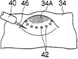
接着,基于图5A、5B、5C、5D、5E及5F说明使用上述的内窥镜用处置工具10进行内窥镜黏膜下层剥离术的方法。以下的实施方式是这样的手术,即,在黏膜34存在病变部34A,以不损伤固有筋层36的方式除去该病变部34A。Next, a method of performing endoscopic submucosal dissection using the aforementioned
首先,根据设于内窥镜插入部40的观察光学系统(未图示)确认病变部34A。此时,从内窥镜插入部40的喷射口散布靛蓝胭脂红等色素而将病变部34A染色即可。First, the
接着,如图5A所示,在病变部34A的周围以规定间隔进行标记42、42...。标记42的方法并未特别地限定,例如使用前端为针状的高频手术刀44。高频手术刀44是将细金属导线插通到绝缘管的内部并使该金属导线的前端从绝缘管的前端突出规定长度的手术刀,金属导线的突出部分成为电极,根据高频电流的流动,切开或切除体腔内壁。Next, as shown in FIG. 5A ,
接下来,如图5B所示,使注射针46插通到内窥镜插入部40的钳子管道中并从前端导出。利用该注射针46,将药液局部注射到病变部34A周围的黏膜34的黏膜下层38(参照图6)。作为药液,一般是生理盐水,但也可使用粘性大的透明质酸钠。这样,通过在病变部34A的整个周围进行局部注射,病变部34A整体变为大的膨胀隆起的状态。Next, as shown in FIG. 5B , the
接下来,从内窥镜插入部40的钳子管道拉拔注射针46,使高频手术刀44插通。如图5C所示,沿标记42、42...的位置,使用高频手术刀44切开病变部34A外周的黏膜34。当结束切开操作时,则如图5D所示,病变部34A的黏膜34收缩,可看到黏膜下层38。Next, the
接下来,从内窥镜插入部40的钳子管道拉拔高频手术刀44,使本实施方式的内窥镜用处置工具10插通到钳子管道中,导出处置部20。从切开位置将该处置部20压入黏膜下层38。接着,如图6所示,使处置部20抵接到病变部34A下方的黏膜下层38。此时,因处置部20的山部30A、30A进入到黏膜下层38的纤维质中,故黏膜下层38的纤维质进入到山部30A、30A之间、即谷部30B中。因黏膜下层38的纤维质与切断设备即电极板32接触,故高频电流集中流动,黏膜下层38被切断。通过反复进行该操作,如图5E所示,病变部34A逐渐从黏膜下层38剥离。由此,如图5F所示,可切除病变部34A。Next, the high-
在进行上述的黏膜下层38的切断(剥离)作业时,即便本体30的下面30C与固有筋层36抵接,由于电极板32从下面30C离开距离h,因而不会与固有筋层36接触。因此,在固有筋层36中高频电流不会集中地流动,故可防止固有筋层36的损伤。When the above-mentioned cutting (peeling) of the
另外,在按压处置部20时,当本体30的山部30A、30A与固有筋层36或黏膜34抵接时,因不是纤维质的固有筋层36或黏膜34不进入谷部30B,故固有筋层36或黏膜34不会被切断。In addition, when the
并且,在本实施方式中,在进行使处置部20向基端侧移动的拉回操作时,也可进行切断。即,在处置部20的拉回操作时,本体30的谷部30D、30D插入纤维质的黏膜下层38之间,黏膜下层38集中到谷部32E并与电极板33接触,故可安全地切断黏膜下层38。此时,因边拉回处置部20边进行切断,故对处置部20容易施加力,可迅速且安全地切断黏膜下层38。In addition, in the present embodiment, the cutting may be performed during the pull-back operation for moving the
这样,因内窥镜用处置工具10仅切断是纤维质的黏膜下层38,故不会误切断固有筋层36或黏膜34,可迅速且安全地进行黏膜下层38的切断。In this way, since the
另外,上述第一实施方式在处置部20的前端侧和基端侧设置山部30A、30D、谷部30B、30E以及电极板32、33,但也可如图37所示,仅在处置部20的前端侧设置山部30A、谷部30B、电极板32。另外,省略图示,也可仅在处置部20的基端侧设置山部30D、谷部30E、电极板33。无论是那种情况,都可安全地进行黏膜下层38的切断。In addition, in the above-mentioned first embodiment, the
接着,参照图7、图8说明第二实施方式的内窥镜用处置工具。图7是表示第二实施方式的内窥镜用处置工具的立体图,图8是表示该处置部的侧面剖面图。在图7、图8中,虽然表示仅在前端侧设置切断部(山部、谷部及电极板)的例子,但在基端侧也设置有与前端侧相同结构的切断部。既可如图7、图8所示仅在前端侧设置切断部,也可仅在基端侧设置切断部(未图示)。Next, an endoscope treatment tool according to a second embodiment will be described with reference to FIGS. 7 and 8 . Fig. 7 is a perspective view showing a treatment tool for an endoscope according to a second embodiment, and Fig. 8 is a side sectional view showing the treatment part. 7 and 8 show examples in which cutouts (mountains, valleys, and electrode plates) are provided only on the distal end, but cutouts having the same structure as the distal end are also provided on the proximal end. As shown in FIGS. 7 and 8 , the cutting portion may be provided only on the distal side, or a cutting portion (not shown) may be provided only on the proximal side.
如这些图所示,第二实施方式的内窥镜用处置工具50在处置部20的谷部30B设有三个电极板32、32、32。电极板32、32、32分别以距本体30的下面30C不同的距离平行地配置。另外,电极板32、32、32分别与不同的导线18、18、18连接,该三条导线18、18、18与便携式操作部14的切换开关52连接。切换开关52构成为以择一地选择三条导线18、18、18中的一条的方式与接线柱22连接。因此,通过操作切换开关52,可选择电极板32、32、32中的任一个而使高频电流在其中流动。另外,导线18、18、18或用非导电性部件的外皮包覆以使其不短路、或以通过非导电性的分隔部件隔开的状态进行配置。As shown in these figures, the
如上所述构成的内窥镜用处置工具50因可选择三个电极板32、32、32中的一个而使高频电流在其中流动,故可在处置部20的本体30的厚度方向选择切断位置。即,根据内窥镜用处置工具50,可在三阶段调整切断深度,可在稳定的深度进行剥离。The
另外,在第二实施方式中,虽然设置三个电极板32、32、32,但电极板32的个数并不限于此,也可选择设置两个或四个以上的电极板32。In addition, in the second embodiment, although three
接着,参照图9、图10说明第三实施方式的内窥镜用处置工具。图9、图10分别是表示第三实施方式的处置部54的主视图、平面剖面图。另外,在图9、图10中,虽然表示仅在前端侧设置切断部(山部、谷部及电极板)的例子,但在基端侧也设置有与前端侧相同结构的切断部。既可如图9、图10所示仅在前端侧设置切断部,也可仅在基端侧设置切断部(未图示)。Next, an endoscope treatment tool according to a third embodiment will be described with reference to FIGS. 9 and 10 . 9 and 10 are a front view and a plan sectional view showing the
第三实施方式的内窥镜用处置工具是在处置部54设置用于使高频电流流动的一对电极的双极型处置工具。即,在处置部54,两个电极板32A、32B设置于本体30的谷部30B。如图9所示,各电极板32A、32B配置成与本体30的下面30C相距规定距离h。另外,如图10所示,该两个电极板32A、32B对置地配置于谷部30B的侧面,各电极板32A、32B电连接有导线18A、18B。导线18A、18B与便携式操作部14(参照图1)的接线柱22连接,通过在接线柱22连接未图示的高频电流供给设备,可对两个电极板32A、32B通电高频电流。另外,两条导线18A、18B或用非导电性部件的外皮包覆以使其不短路、或利用非导电性的分隔部件隔开地设置。The endoscope treatment tool according to the third embodiment is a bipolar treatment tool in which a pair of electrodes for passing a high-frequency current is provided in a
如上所述构成的内窥镜用处置工具通过在一对电极板32A、32B之间使高频电流流动而切断体组织。因此,仅切断进入到谷部30B的纤维质的黏膜下层38,故不会切断黏膜34或固有筋层36,可安全且迅速地切断黏膜下层38。The endoscopic treatment instrument configured as described above cuts the body tissue by flowing a high-frequency current between the pair of
另外,因上述内窥镜用处置工具为双极型,故不需要安装在被检测者身上的极板(未图示),并且,穿孔的风险小且高频电流对周围部位的影响小。In addition, since the above-mentioned endoscope treatment tool is a bipolar type, there is no need for an electrode plate (not shown) attached to the subject, and the risk of perforation is small, and the influence of high-frequency current on surrounding parts is small.
另外,两个电极板32A、32B的配置并不限于上述实施方式,例如也可将两个电极板32A、32B在不同的高度(深度)位置平行地设置。In addition, the arrangement of the two
接下来参照图11、图12说明第四实施方式的内窥镜用处置工具。图11、图12分别是表示第四实施方式的处置部56的主视图及平面剖面图。在图11、图12中,虽然表示仅在前端侧设置切断设备的例子,但在基端侧也设置有与前端侧相同结构的切断部(山部、谷部及电极板)。既可如图11、图12所示仅在前端侧设置切断部,也可仅在基端侧设置切断部(未图示)。Next, an endoscope treatment tool according to a fourth embodiment will be described with reference to FIGS. 11 and 12 . 11 and 12 are a front view and a plan sectional view showing a
在这些图所示的内窥镜用处置工具的处置部56中,本体30形成为具有三个山部30A、30A、30A和两个谷部30B、30B的锯齿状,在谷部30B、30B分别设有电极板32、32。各电极板32、32经由金属板58与一条导线18电连接,该导线18与便携式操作部14(参照图1)的接线柱22连接。因此,通过在接线柱22连接高频电流供给设备(未图示),可从两个电极板32、32同时流动高频电流。In the
如上所述构成的内窥镜用处置工具由于可在两个谷部30B、30B同时切断黏膜下层38(参照图6),故切断面积增大,可有效地进行黏膜下层38的切断。The endoscopic treatment tool configured as described above can simultaneously cut the
另外,谷部30B、30B的个数并不限于一个或两个,也可设置三个以上的谷部30B,在各谷部30B设置电极板32。这样,这样通过设置多个谷部30B,切断范围变宽广,可进一步迅速地进行黏膜下层38的切断。即便是设置多个谷部30B、30B的情况,也可如第二实施方式那样,构成为在各谷部30B设置多个电极板32并选择切断深度,或在一个谷部30B设置两个电极而构成双极型。In addition, the number of
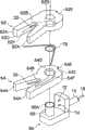
接下来参照图13、图14说明第五实施方式的内窥镜用处置工具。图13、图14分别是表示第五实施方式的处置部60的立体图及分解立体图。Next, an endoscope treatment tool according to a fifth embodiment will be described with reference to FIGS. 13 and 14 . 13 and 14 are a perspective view and an exploded perspective view showing the
如这些图所示,处置部60主要由上片62、下片64及承载台66构成。承载台66固定在挠性筒16的前端。另外,在承载台66上设有摇动自如地支承上片62及下片64的轴体68。在轴体68的上端设有凸缘68A,通过与后述的上片62卡合,可防止上片62的脱落。并且,在承载台66上竖直设置有用于限制上片62及下片64的摇动范围的限制销72、74。As shown in these figures, the
上片62形成为大致V字形状,具有山部62A、62A和谷部62B。在谷部62B设有电极板32,在将上片62安装到承载台66时,该电极板32与导线18电连接。另外,在上片62设有孔62D,通过使承载台66的轴体68插通该孔62D,上片62摇动自如地被承载台66支承。在上片62形成有限制槽62E,在该限制槽62E中卡合有前述的限制销72,上片62的摇动范围被限制。在上片62的下面62C形成有槽62F,在其内部配设有后述的弹簧76。The
下片64与上片同样地形成为大致V字形状,具有山部64A、64A和谷部64B。在谷部64B设有电极板32,在将下片64安装到承载台66时,该电极板32与导线18电连接。另外,在下片64形成有孔64D,通过使承载台66的轴体68插通该孔64D,下片64摇动自如地被承载台66支承。在下片64形成有限制槽64E,在该限制槽64E中卡合有前述的限制销74,下片64的摇动范围被限制。在下片64的上面64C形成有槽64F,在该槽64F的内部配设有弹簧76。通过将弹簧76配置在上片62的槽62F和下片64的槽64F的内部,如图13所示,上片62和下片64向宽广的方向施加作用力。The
如上所述构成的内窥镜用处置工具其上片62及下片64被摇动自如地支承。因此,通过将上片62和下片64重合,可缩小处置部56,使处置部56插通到内窥镜插入部40(参照图5)的钳子管道中。In the treatment tool for endoscope configured as described above, the
另外,在将处置部56从钳子管道导出时,因上片62和下片64根据弹簧76的作用力而打开,故电极板32、32的切断范围变宽广,可有效地进行切断作业。In addition, when the
上述第五实施方式构成为通过使上片62和下片64摇动,山部彼此间的间隔或打开或关闭,但其结构并不限于上述实施方式。例如,图22A及图22B所示的内窥镜处置工具的处置部20其本体30由非导电性的橡胶构成,电极板32、32由导电性的橡胶构成,电极板32、32与本体30粘接。本体30在没有负荷的状态下如图22B所示,山部30A、30A、30A彼此间的间隔打开。如图22A所示,该本体30可弹性变形以使山部30A、30A、30A彼此间的间隔缩小,在该状态下可使其插通到内窥镜的钳子管道(未图示)中。处置部20在从钳子管道导出时,如图22B所示,本体30恢复到原来的形状,山部30A、30A、30A彼此间的间隔扩展。因此,因谷部30B、30B扩展,故可根据电极板32、32在宽广的范围内进行黏膜下层38的切断。In the fifth embodiment described above, the gap between the mountain portions is opened or closed by shaking the
另外,上述第一~第五实施方式通过将山部30A和谷部30B排列成直线状而将处置部20的本体30形成为锯齿状,但本体30的形状并不限于此,也可将山部30A和谷部30B配置成圆周状而将本体30形成为齿轮状。以下,说明该实施方式。In addition, in the above-mentioned first to fifth embodiments, the
图15是表示第六实施方式的内窥镜用处置工具80的立体图。另外,图16是该处置部82的侧视图,图17是沿图16的17-17线的、处置部82的剖面图。FIG. 15 is a perspective view showing an
如这些图所示,在挠性筒16的前端安装有处置部82的本体84。处置部82的本体84形成为齿轮状,在本体84的外周面上,U状或V状的多个谷部(槽)84B以一定间隔形成。即,在本体84的外周面上,山部84A和谷部84B相互交替地反复形成。在各谷部84B设有由金属等导体构成的电极部86B。如图17所示,电极部86B通过埋入本体84内部的一张金属板86而构成,通过使该金属板86的一部分在谷部82B向外部露出而形成电极部86B。金属板86与导线18电连接,该导线18被插通到挠性筒16中,与便携式操作部14的接线柱22连接。因此,通过在接线柱22连接未图示的高频电流供给设备,可向各电极部86B通电高频电流。As shown in these figures, the
如图16所示,电极部86B配置成与本体84的底面84C相距规定距离h,在使底面84C与固有筋层36(参照图6)抵接时,电极部86B与固有筋层36不接触。另外,电极部86B、86B...也可构成为在各谷部84B分别配置导体。As shown in FIG. 16 , the
如上所述构成的内窥镜用处置工具80如图18所示,从内窥镜插入部40的钳子管道导出处置部82,将该处置部82向导出方向(箭头A方向)挤出,相对于切开后的黏膜下层38而靠近。接着,使处置部82对应每个内窥镜插入部40向本体84的径向(箭头B方向)移动。由此,本体84的山部84A、84A...进入黏膜下层38的纤维质,该黏膜下层38的纤维质集中到谷部84B、84B...。接下来,因黏膜下层38的纤维质与谷部84B的电极部86B接触,故在黏膜下层38高频电流集中地流动而将其切断。As shown in FIG. 18 , the
这样,内窥镜用处置工具80仅通过使处置部82沿本体84的径向移动即可容易地切断黏膜下层38。此时,因处置部82始终配置于内窥镜插入部40的前方,故可始终根据内窥镜观察切断作业,可容易地进行操作。In this way, the
另外,因内窥镜用处置工具80在本体84的谷部84B设有电极部86B,故可仅切断是纤维质的黏膜下层38。即,在不是纤维质的黏膜或固有筋层36这种情况下,因不会与山部84A、84A...抵接而进入谷部84B、84B,故不会因电极部86B而损伤黏膜34或固有筋层36。并且,因内窥镜用处置工具80中将电极部86B配置成与本体84的下面84C相距规定的距离h,故即便本体84的下面84C与固有筋层36抵接,固有筋层36也不会被切断。因此,根据内窥镜用处置工具80,可安全且迅速地仅切断黏膜下层38。In addition, since the
另外,因内窥镜用处置工具80向从钳子管道导出的导出方向挤出并向黏膜下层38靠近,故容易向切断部分靠近,操作性良好。In addition, since the
在上述内窥镜用处置工具80的情况下,既可构成为如第二实施方式那样可调节切断深度,也可构成双极型处置工具。In the case of the above-mentioned
另外,在上述第一~第六实施方式中,山部30A、62A、64A、84A的形状并未特别地限定,优选为如下形状,即,可容易地插入是纤维质的黏膜下层38、且可防止固有筋层36的切断。例如,如图23A、图23B所示,前端侧的山部30A、30A形成为越靠近前端则变得越细的大致圆锥状的前端细的形状,并且山部30A、30A的前端倒圆角而形成,具有非切开性。由此,可容易地将山部30A、30A插入到是纤维质的黏膜下层38中,并且,当山部30A、30A与固有筋层36抵接时,可防止损伤固有筋层36。另外,图23A、图23B表示仅在前端侧设置切开设备的例子,优选在基端侧也设置相同结构的切断设备。即,将基端侧的山部30D、30D(参照图3、图4)形成为越靠近前端则变得越细的大致圆锥状的前端细的形状、且在前端设置圆角而具有非切开性。另外,在仅在基端侧设置切断设备的情况下也可同样地构成。In addition, in the above-mentioned first to sixth embodiments, the shapes of the
同样地,也可将图16、图17所示的山部84A、84A形成为图24A、图24B所示的形状。图24A、图24B所示的山部84A、84A形成为越靠近前端则变得越细的大致圆锥状的前端细的形状,并且其前端倒圆角而具有非切开性。由此,可容易地将山部84A、84A插入到是纤维质的黏膜下层38中,并且,当山部84A、84A与固有筋层36抵接时,可防止损伤固有筋层36。Similarly, the
接下来,基于图25~图28说明第七实施方式的内窥镜用处置工具。图25~图27分别是表示第七实施方式的处置部130的立体图、平面剖面图、侧面剖面图,图28是从基端方向看处置部130的后视图。Next, an endoscope treatment tool according to a seventh embodiment will be described based on FIGS. 25 to 28 . 25 to 27 are a perspective view, a plan sectional view, and a side sectional view showing the
如这些图所示的第七实施方式的处置部130在非导电性本体132的前端侧和基端侧分别设有切断设备。即,在本体132的前端侧设有电极板134,在本体132的基端侧设有电极板136。The
处置部130的本体132在前端侧具有两个山部132A、132A,在该山部132A、132A之间形成有谷部132B,并且,在基端侧具有两个山部132C、132C,在该山部132C、132C之间形成有谷部132D。另外,前端侧的山部132A、132A的间隔形成为比基端侧的山部132C、132C的间隔小,在整个本体132中,前端侧形成为比基端侧小。另外,本体132的大小实质上形成为比内窥镜的钳子管道的内尺寸小,可插通到内窥镜的钳子管道中。The
如图26的平面图及图27的侧视图所示,山部132A及山部132C构成为,形成前端逐渐变细的大致圆锥状的前端细的形状,并且其前端倒圆角而具有非切开性。因此,可顺畅地将山部132A和山部132C插入纤维质的黏膜下层38,并且,在将山部132A、132C与固有筋层36抵接时,可防止固有筋层36被切断。As shown in the plan view of FIG. 26 and the side view of FIG. 27 , the
在谷部132B、谷部132D分别设有电极板134、136。如图27所示,电极板134、136设置于本体132厚度方向的大致中间位置,在固有筋层36与本体132的上下面接触时,固有筋层36与电极板134、136不接触。另外,如图26所示,电极板134、136配置于谷部132B、132D的内部、即从山部132A的顶点或山部132C的顶点离开的位置,在将山部132A的顶点或山部132C的顶点与固有筋层36抵接时,电极板134、136与固有筋层36不接触。另外,电极板134和电极板136通过导体138电连接,进而与导线18连接。
如上所述构成的第七实施方式的处置部130在切断黏膜下层38时,首先,通过使本体132向前端侧移动而压入黏膜下层38的内部。由此,前端侧的山部132A、132A被插入纤维质的黏膜下层38,黏膜下层38集中到谷部132B而与电极板134接触。由此,高频电流在黏膜下层38中流动,黏膜下层38被切断。因此,可边切断黏膜下层38边将处置部130向前端侧前进。The
在将整个本体132压入黏膜下层38后,使本体132向基端侧移动,进行退回操作。由此,本体132的基端侧的山部132C、132C插入纤维质的黏膜下层38间,黏膜下层38集中到谷部132D而与电极板136接触。由此,高频电流在黏膜下层38中流动,黏膜下层38被切断。因此,可边切断黏膜下层38边将处置部130向前端侧前进。After the
接着,进行再次将处置部130向前端侧前进并切除黏膜下层38的压入切除操作,此后,进行将处置部130向基端侧拉回并切除黏膜下层38的退回切除操作。这样,通过反复进行压入切除操作和退回切除操作,黏膜下层38被切断。因此,根据第七实施方式,因在处置部130压入时和退回时都切断黏膜下层38,故可迅速地进行黏膜下层38的切断。Next, the operation of pressing and cutting the
特别是,在第七实施方式中,因边退回处置部130边切断黏膜下层38,故力容易地传递到黏膜下层38,可切实地切断黏膜下层38。另外,在边退回边切断时,因在处置部130的基端侧进行切断,故可边从内窥镜的观察光学系统观察切断部分边进行操作。In particular, in the seventh embodiment, since the
另外,上述第七实施方式在处置部130的前端侧和基端侧都设置切断设备,但也可仅在基端侧设置切断设备。即,在图25~图28的处置工具中,也可将本体132的前端侧形成为前端侧变小的前端细的形状、且其前端倒圆角的形状。此时,在使本体132向前端侧移动并压入纤维质的黏膜下层38后,通过将本体132退回,从而可切断黏膜下层38。另外,在上述第七实施方式中,也可仅在前端侧设置切断设备。此时,基端侧优选为退回时不形成大的阻力的形状。In addition, in the seventh embodiment described above, the cutting device is provided on both the distal side and the proximal side of the
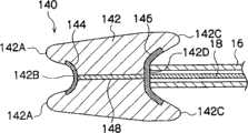
接下来,基于图29~图32说明第八实施方式的内窥镜用处置工具。图29~图32分别是表示第八实施方式的处置部140的立体图、平面剖面图、从前端侧看的主视图、从基端侧看的后视图。Next, an endoscope treatment tool according to an eighth embodiment will be described based on FIGS. 29 to 32 . 29 to 32 are a perspective view, a plan sectional view, a front view from the front end side, and a rear view from the base end side, respectively, showing the
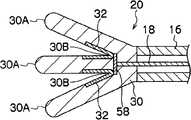
如这些图所示的第八实施方式的处置部140的非导电性本体142形成为使四个板部件组合成十字状的形状。即,本体142以90°间隔配置四个板部件,形成在处置部140的中心轴侧连结的十字状。The non-conductive
本体142的前端侧因各板部件的外周部分向前端侧突出而形成有四个山部142A、142A...。在山部142A、142A...间、即中央部分形成有谷部142B。同样地,本体142的基端侧因各板部件的外周部分向基端侧突出而形成有山部142C、142C...,在这些山部142C、142C...间形成有谷部142D。The front end side of the
如图31所示,在前端侧的谷部142B设有十字状的电极板144。电极板144从各山部142A的顶点分离而配置,即便山部142A与固有筋层36接触,电极板144也不与固有筋层36接触。同样地,如图32所示,在基端侧的谷部142D设有十字状的电极板146。电极板146从各山部142C分离而配置,即便山部142C与固有筋层36接触,电极板146也不与固有筋层36接触。如图30所示,电极板144和电极板146由导体148电连接,进而,电极板146与导线18电连接。As shown in FIG. 31 , a
另外,本体142形成为其前端侧比基端侧小,容易将本体142压入黏膜下层38。另外,本体142的各山部142A、142C形成为前端侧变小、且其前端倒圆角而具有非切开性。因此,容易将山部142A和山部142C压入纤维质的黏膜下层38,并且可防止因山部142A和山部142C而损伤固有筋层36。另外,本体142的大小实质上形成为比内窥镜的钳子管道的内尺寸小,可无障碍地插通到内窥镜的钳子管道中。In addition, the
如上所述构成的第八实施方式与第七实施方式同样地,通过反复进行边将处置部140向前端侧靠近边切断黏膜下层38的压入切断操作、和边将处置部140向基端侧退回边切断黏膜下层38的退回切断操作,从而切断黏膜下层38。因此,因在处置部140的压入时和退回时都切断黏膜下层38,故可迅速地切断黏膜下层38。In the eighth embodiment configured as described above, similarly to the seventh embodiment, the pressing and cutting operation of cutting the
另外,根据第八实施方式,因电极板144、146配置于处置工具140的中央(中心轴侧),故即便处置工具140绕轴线旋转,电极板144、146也始终配置于中央。因此,不受处置部140的姿势的影响,可进行黏膜下层38的切断。In addition, according to the eighth embodiment, since the
另外,上述第八实施方式在处置部140的前端侧和基端侧都设有切断设备,但也可仅在基端侧设置切断设备。即,也可将本体142的前端侧形成为前端侧变小的前端细的形状、且其前端倒圆角的形状。In addition, in the eighth embodiment described above, the cutting device is provided on both the distal side and the proximal side of the
另外,上述第八实施方式将四个板状部件组合而形成本体142,但板状部件的个数也可为三个或五个以上。无论是那种情况,优选为以相等的角度间隔配置板状部件。In addition, in the eighth embodiment described above, four plate-shaped members are combined to form the
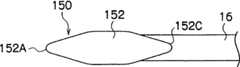
接下来,基于图33~图36说明第九实施方式的内窥镜处置工具。图33、图34分别是表示第九实施方式的处置部150的平面剖面图、侧视图。图35表示向前端侧移动时的处置部150,图36表示向基端侧移动时的处置部150。Next, an endoscope treatment tool according to a ninth embodiment will be described based on FIGS. 33 to 36 . 33 and 34 are a plan sectional view and a side view showing the
这些图所示的处置部150的本体152由非导电性橡胶等弹性部件形成工字状(或H形状)。因此,本体152在前端侧具有山部152A、152A,在它们之间形成有谷部152B,并且,在基端侧具有山部152C、152C,在它们之间形成有谷部152D。如图33及图34所示,各山部152A及各山部152C构成为前端侧逐渐变细的前端细的形状、且其前端倒圆角而具有非切开性。The
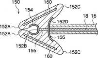
在谷部152B、152D分别设有电极体154、156。电极体154、156在本体152的厚度方向配置于大致中间位置。另外,电极体154、156配置成不与山部152A或山部152C的顶点接触。电极体154和电极体156由导体158连接,进而,电极体156与导线18连接。电极体154、156由导电性橡胶等具有导电性的弹性部件构成,与本体152同时弹性变形。
在本体152的内部埋入有刚体160、160。刚体160配置于与前端侧的山部152A和基端侧的山部152C连接的位置。因此,由弹性部件构成的本体152,除刚体进入的部分之外,其余部分弹性变形。具体地说,或如图35所示,以前端侧的山部152A、152A的间隔扩展而基端侧的山部152C、152C的间隔缩小的方式弹性变形,或如图36所示,以前端侧的山部152A、152A的间隔缩小而基端侧的山部152C、152C的间隔扩展的方式弹性变形。另外,在自然状态下,如图33所示,刚体160、160相互平行,处置部150的最大外径尺寸变得最小。
如上所述构成的第九实施方式的处置部150在黏膜下层38的内部向前端侧靠近时,黏膜下层38成为阻挡,如图35所示,山部152A、152A彼此间的间隔自动扩展。因此,可在前端侧的谷部152B集中大范围的黏膜下层38,通过谷部152B的电极体154可迅速地切断黏膜下层38。In the
另外,若将处置部150在黏膜下层38的内部向基端侧靠近,则基端侧的黏膜下层38成为阻挡,如图36所示,山部152C、152C彼此间的间隔自动扩展。因此,可在前端侧的谷部152D集中大范围的黏膜下层38,通过谷部152D的电极体156可迅速地切断黏膜下层38。In addition, when the
根据第九实施方式的处置部150,因切断后的本体152恢复到图34所示的自然状态,故本体152的最大外径尺寸变小,可容易地使处置部150插通到内窥镜的钳子管道中。According to the
另外,在上述第九实施方式中,优选构成为可在处置部150的最大外径尺寸最小的状态下(即图33的状态)进行固定。例如,在山部152C、152C设置从基端侧嵌入的环状的嵌合部件,沿筒16滑动自如地设置该嵌合部件,并且在便携式操作部14设置嵌合部件的滑动操作设备即可。此时,因可使用嵌合部件固定处置部150的山部152C、152C,故可在处置部150的最大外径尺寸最小的状态下固定,可切实地使处置部150插通到内窥镜的钳子管道中。In addition, in the ninth embodiment described above, it is preferable to be configured so that it can be fixed in a state where the maximum outer diameter of the
上述第一~第九实施方式将各处置部20、54、56、60、82、130、140、150紧固在挠性筒16的前端,但不并限于此,也可经由活动机构支承各处置部20、54、56、60、82、130、140、150。In the above-mentioned first to ninth embodiments, each
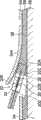
图19是在处置部82和挠性筒16间设置弯曲部92(活动机构)的内窥镜用处置工具90的剖面图。FIG. 19 is a cross-sectional view of an
如图所示,处置部82被由多个(例如五个)杯状部件100、100...构成的弯曲部92支承。在各杯状部件100形成有孔100A,在该孔100A中插通有导线18。导线18其前端固定于处置部82的本体84,并且,基端与便携式操作部14的滑块94连结。滑块94被便携式操作部14的本体96滑动自如地支承,通过操作设于滑块94的锁定螺钉98,可进行滑块94和本体96的锁定及锁定解除。另外,在滑块94形成有用于放置手术大夫的食指和中指的凸缘94A,在本体96的基端形成有用于放置手术大夫的大拇指的环部96A。As shown in the figure, the
挠性筒16的基端紧固于便携式操作部14的本体96,其前端紧固于最基端侧的杯状部件100。另外,挠性筒16具有合适的刚性,在使滑块94向基端侧滑动而增大导线18的张力时,挠性筒16不折断或压坏。The base end of the
弯曲部92被由橡胶等软性材料构成的包覆管102包覆。包覆管102的前端紧固于处置部82的本体84,包覆管102的基端安装于挠性筒16的基端。The
如上所述构成的内窥镜用处置工具90使便携式操作部14的滑块94相对于本体96向前端侧滑动,从而降低导线18的张力,各杯状部件100彼此间的摩擦减小。因此,可使弯曲部92自由弯曲,例如可如图20所示进行弯曲。In the
与此相反,若使滑块94向本体96的基端侧滑动,则导线18的张力上升,各杯状部件100彼此间的摩擦增大。因此,弯曲部92以该形状被固定。由此,在使弯曲部92弯曲时,可保持其弯曲形状地固定。在该状态下,通过紧固锁定螺钉98,可维持弯曲状态。On the contrary, when the
这样,根据内窥镜用处置工具90,因可使弯曲部92弯曲,故可自由地调节并固定处置部82的姿势。由此,处置部82向黏膜下层38的靠近变得容易,并且,可容易地进行黏膜下层38的切断作业。In this way, according to the
另外,各处置部20、54、56、60、82、130、140、150的活动机构并不限于上述实施方式,例如,也可如图21所示构成。图21所示的内窥镜用处置工具110的处置部82经由弯曲部112而被支持。弯曲部112具有圆筒状的多个调节环114、114...,调节环114彼此通过销116旋转自如地连结。多个调节环114中位于前端的调节环114紧固于处置部82,在该调节环114固定有操作导线118、118的前端。操作导线118、118被插通到挠性筒16内并卷绕在便携式操作部14的带轮120上。因此,利用旋钮(未图示)等使带轮120旋转,从而对操作导线118、118进行推拉操作,调节环114、114...转动,弯曲部112被弯曲操作。In addition, the movable mechanism of each
根据如上所述构成的内窥镜用处置工具110,可使弯曲部112自由地弯曲,可自由调整处置部82的姿势。因此,处置部82向黏膜下层38的靠近变得容易,并且,可容易地进行黏膜下层38的切断作业。According to the
另外,在图21中,虽然表示了仅在两方向(上和下)弯曲的弯曲结构,但弯曲方向并不限于此,也可构成在上下左右四个方向弯曲的结构。In addition, in FIG. 21, although the bending structure which bends only in two directions (up and down) is shown, the bending direction is not limited to this, The structure which bends in four directions of up, down, left, and right may also be comprised.
各处置部20、54、56、60、82、130、140、150的活动机构例如或使用齿条和小齿轮使处置部82转动,或使用由形状记忆材料构成的线状部件支承处置部82,对该线状部件通电加热而使其变形,从而改变处置部82的姿势。The movable mechanism of each
另外,上述实施方式的切断设备使高频电流流动而进行切断,但切断设备的种类并不限于此,也可使用利用激光或超声波的切断设备。例如,在上述电极板32、33、86B、134、136、144、146、154、156的位置配置光纤的前端部,使该光纤插通到挠性筒16中,并且,使光纤的基端部与激光振荡装置连接。由此,因激光照射到进入谷部的黏膜下层38,故可使用激光切断黏膜下层38。此时,激光的照射设备可以设置于谷部内部的一山部侧而向另一山部侧照射激光。由此,可切实地仅切断进入谷部的黏膜下层38。另外,在使用根据超声波的切断设备时,在上述电极板32、33、86B、134、136、144、146、154、156的位置配置超声波振荡元件,使与其连接的导线插通到挠性筒16的内部,并与外部的驱动电路连接。由此,朝进入谷部的黏膜下层38振荡超声波,黏膜下层38因超声波而被切断。In addition, although the cutting device of the above-described embodiment cuts by flowing a high-frequency current, the type of cutting device is not limited thereto, and a cutting device using laser light or ultrasonic waves may also be used. For example, at the positions of the above-mentioned
在上述第一~第九实施方式中,各处置部20、54、56、60、82、130、140、150的大小优选形成为比内窥镜的钳子管道实质上小,可插通到内窥镜的钳子管道中。实质上,小指的是可无障碍地将各处置部20、54、56、60、82、130、140、150引入到内窥镜的钳子管道中,例如,使用橡胶等弹性材料构成本体30、84、132、142、152,并且,在其外周部设置圆角时,即使本体30、84、132、142、152的外尺寸比钳子管道的内尺寸大10%左右也可无障碍地引入到钳子管道中,故处置部20、54、56、60、82、130、140、150的优选大小为相对于钳子管道内尺寸的大约110%以下。In the above-mentioned first to ninth embodiments, the size of each
Claims (10)
Translated fromChineseApplications Claiming Priority (2)
| Application Number | Priority Date | Filing Date | Title |
|---|---|---|---|
| JP2005-278473 | 2005-09-26 | ||
| JP2005278473 | 2005-09-26 |
Related Parent Applications (1)
| Application Number | Title | Priority Date | Filing Date |
|---|---|---|---|
| CN2006800353539ADivisionCN101272744B (en) | 2005-09-26 | 2006-09-12 | Treatment tool for endoscope |
Publications (2)
| Publication Number | Publication Date |
|---|---|
| CN101803949Atrue CN101803949A (en) | 2010-08-18 |
| CN101803949B CN101803949B (en) | 2011-11-09 |
Family
ID=37888759
Family Applications (3)
| Application Number | Title | Priority Date | Filing Date |
|---|---|---|---|
| CN2006800353539AActiveCN101272744B (en) | 2005-09-26 | 2006-09-12 | Treatment tool for endoscope |
| CN2010101433134AActiveCN101803949B (en) | 2005-09-26 | 2006-09-12 | Instrument for endoscopic treatment |
| CN2010101433149AActiveCN101810511B (en) | 2005-09-26 | 2006-09-12 | Instrument for endoscopic treatment |
Family Applications Before (1)
| Application Number | Title | Priority Date | Filing Date |
|---|---|---|---|
| CN2006800353539AActiveCN101272744B (en) | 2005-09-26 | 2006-09-12 | Treatment tool for endoscope |
Family Applications After (1)
| Application Number | Title | Priority Date | Filing Date |
|---|---|---|---|
| CN2010101433149AActiveCN101810511B (en) | 2005-09-26 | 2006-09-12 | Instrument for endoscopic treatment |
Country Status (6)
| Country | Link |
|---|---|
| US (1) | US9220560B2 (en) |
| EP (3) | EP1943972B1 (en) |
| JP (1) | JP4794564B2 (en) |
| KR (2) | KR101278555B1 (en) |
| CN (3) | CN101272744B (en) |
| WO (1) | WO2007034708A1 (en) |
Cited By (1)
| Publication number | Priority date | Publication date | Assignee | Title |
|---|---|---|---|---|
| CN103415265A (en)* | 2011-02-22 | 2013-11-27 | 世洋医疗器械株式会社 | Multi-procedural tool for endoscopic submucosal layer which operates plurality of modes in one device through a multi-procedure module |
Families Citing this family (19)
| Publication number | Priority date | Publication date | Assignee | Title |
|---|---|---|---|---|
| ATE507791T1 (en) | 2008-09-30 | 2011-05-15 | Univ Jichi Medical | TREATMENT INSTRUMENT FOR ENDOSCOPES |
| EP2453807A4 (en)* | 2009-07-17 | 2017-06-21 | Richard B. North | Shaped electrode and dissecting tool |
| EP2380482A1 (en)* | 2010-04-21 | 2011-10-26 | Koninklijke Philips Electronics N.V. | Extending image information |
| EP2677961B1 (en) | 2011-02-24 | 2024-12-11 | Eximo Medical Ltd. | Hybrid catheter for vascular intervention |
| CN102138824B (en)* | 2011-04-29 | 2012-10-10 | 田成龙 | Multifunctional operating device for laparoscope |
| KR101356607B1 (en)* | 2012-06-26 | 2014-02-03 | 신경민 | High-frequency treatment device |
| US9526570B2 (en)* | 2012-10-04 | 2016-12-27 | Cook Medical Technologies Llc | Tissue cutting cap |
| KR101479686B1 (en)* | 2012-10-18 | 2015-01-07 | 국립암센터 | Surgical instrument for medical |
| TWI482609B (en)* | 2012-12-19 | 2015-05-01 | Metal Ind Res & Dev Ct | Endoscope controlled device |
| EP3050525A4 (en) | 2013-09-27 | 2017-05-17 | Olympus Corporation | Probe unit, treatment tool and treatment system |
| EP3050528A4 (en) | 2013-09-27 | 2017-06-21 | Olympus Corporation | Probe unit, treatment tool, and treatment system |
| WO2015045431A1 (en)* | 2013-09-27 | 2015-04-02 | オリンパスメディカルシステムズ株式会社 | Probe unit, treatment tool and treatment system |
| US10398461B2 (en)* | 2013-11-08 | 2019-09-03 | The Cleveland Clinic Foundation | Excising endocap |
| CN109414292A (en) | 2016-05-05 | 2019-03-01 | 爱克斯莫医疗有限公司 | Device and method for cutting off and/or melting unwanted tissue |
| US10293061B2 (en)* | 2016-12-06 | 2019-05-21 | Shiu Kum LAM | Two-endoscope technique of endoscopic mucosal resection and kit with a set of endoscopes for the method |
| JP7183302B2 (en)* | 2018-12-27 | 2022-12-05 | オリンパス株式会社 | Electrode unit and endoscope system |
| US12376904B1 (en) | 2020-09-08 | 2025-08-05 | Angiodynamics, Inc. | Dynamic laser stabilization and calibration system |
| US12038322B2 (en) | 2022-06-21 | 2024-07-16 | Eximo Medical Ltd. | Devices and methods for testing ablation systems |
| US20250241671A1 (en)* | 2024-01-31 | 2025-07-31 | Boston Scientific Scimed, Inc. | Medical systems and devices for tissue marking and/or removal and related methods |
Family Cites Families (27)
| Publication number | Priority date | Publication date | Assignee | Title |
|---|---|---|---|---|
| AU4945490A (en) | 1989-01-06 | 1990-08-01 | Angioplasty Systems Inc. | Electrosurgical catheter for resolving atherosclerotic plaque |
| FR2662084A1 (en)* | 1990-05-21 | 1991-11-22 | Souriau & Cie | ANNULAR NEURAL ELECTRODE. |
| US5549605A (en)* | 1995-04-20 | 1996-08-27 | Symbiosis Corporation | Roller electrodes for electrocautery probes for use with a resectoscope |
| JP3655664B2 (en) | 1995-05-02 | 2005-06-02 | オリンパス株式会社 | High frequency knife |
| CN1155833A (en)* | 1995-06-20 | 1997-07-30 | 伍云升 | Articulated arm for medical procedures |
| US6015406A (en) | 1996-01-09 | 2000-01-18 | Gyrus Medical Limited | Electrosurgical instrument |
| US5634924A (en) | 1995-08-28 | 1997-06-03 | Symbiosis Corporation | Bipolar roller electrodes and electrocautery probes for use with a resectoscope |
| US5766215A (en)* | 1995-09-27 | 1998-06-16 | Endocare, Inc. | Electrosurgical loop providing enhanced tissue coagulation |
| US6896672B1 (en)* | 1995-11-22 | 2005-05-24 | Arthrocare Corporation | Methods for electrosurgical incisions on external skin surfaces |
| JPH09262239A (en)* | 1996-03-28 | 1997-10-07 | Fuji Photo Optical Co Ltd | Treating tool for endoscope |
| DE19625242A1 (en)* | 1996-06-24 | 1998-04-30 | Storz Karl Gmbh & Co | Electrode for HF surgery with a smooth surface and heterogeneous structure |
| US6805128B1 (en)* | 1996-10-22 | 2004-10-19 | Epicor Medical, Inc. | Apparatus and method for ablating tissue |
| JP2002515801A (en)* | 1997-02-12 | 2002-05-28 | オーレイテック インターヴェンションズ インコーポレイテッド | Concave tip for arthroscopic surgery |
| US5925040A (en)* | 1997-06-18 | 1999-07-20 | Medical Scientific, Inc. | Electrosurgical instrument having a segmented roller electrode |
| US6273887B1 (en)* | 1998-01-23 | 2001-08-14 | Olympus Optical Co., Ltd. | High-frequency treatment tool |
| US6142993A (en)* | 1998-02-27 | 2000-11-07 | Ep Technologies, Inc. | Collapsible spline structure using a balloon as an expanding actuator |
| US6974450B2 (en)* | 1999-12-30 | 2005-12-13 | Pearl Technology Holdings, Llc | Face-lifting device |
| US7494488B2 (en)* | 1998-05-28 | 2009-02-24 | Pearl Technology Holdings, Llc | Facial tissue strengthening and tightening device and methods |
| CN2410979Y (en)* | 2000-01-18 | 2000-12-20 | 俞南 | Rotary vaporization electric excision mirror |
| JP4316821B2 (en)* | 2000-05-04 | 2009-08-19 | エルベ エレクトロメディジン ゲーエムベーハー | Surgical instruments that require minimal insertion |
| JP3839320B2 (en)* | 2001-12-28 | 2006-11-01 | オリンパス株式会社 | Biological tissue cutting treatment tool |
| EP1323392B1 (en)* | 2001-12-28 | 2011-02-09 | Olympus Corporation | Treatment device for cutting living tissue |
| JP4109092B2 (en)* | 2002-11-21 | 2008-06-25 | オリンパス株式会社 | High frequency knife |
| JP4068989B2 (en)* | 2003-02-20 | 2008-03-26 | オリンパス株式会社 | High frequency treatment tool |
| JP4320194B2 (en) | 2003-03-19 | 2009-08-26 | Hoya株式会社 | Endoscopic high frequency knife |
| JP4197983B2 (en)* | 2003-04-28 | 2008-12-17 | オリンパス株式会社 | High frequency treatment tool |
| US7169115B2 (en)* | 2003-09-29 | 2007-01-30 | Ethicon Endo-Surgery, Inc. | Endoscopic mucosal resection device with overtube and method of use |
- 2006
- 2006-09-12EPEP06797839.5Apatent/EP1943972B1/enactiveActive
- 2006-09-12KRKR1020087007289Apatent/KR101278555B1/enactiveActive
- 2006-09-12CNCN2006800353539Apatent/CN101272744B/enactiveActive
- 2006-09-12EPEP12197490.1Apatent/EP2572666B1/enactiveActive
- 2006-09-12USUS11/992,515patent/US9220560B2/enactiveActive
- 2006-09-12EPEP12197488.5Apatent/EP2572667B1/enactiveActive
- 2006-09-12JPJP2007536455Apatent/JP4794564B2/enactiveActive
- 2006-09-12KRKR1020137000530Apatent/KR101278556B1/enactiveActive
- 2006-09-12CNCN2010101433134Apatent/CN101803949B/enactiveActive
- 2006-09-12WOPCT/JP2006/318032patent/WO2007034708A1/enactiveApplication Filing
- 2006-09-12CNCN2010101433149Apatent/CN101810511B/enactiveActive
Cited By (1)
| Publication number | Priority date | Publication date | Assignee | Title |
|---|---|---|---|---|
| CN103415265A (en)* | 2011-02-22 | 2013-11-27 | 世洋医疗器械株式会社 | Multi-procedural tool for endoscopic submucosal layer which operates plurality of modes in one device through a multi-procedure module |
Also Published As
| Publication number | Publication date |
|---|---|
| EP2572666A1 (en) | 2013-03-27 |
| JP4794564B2 (en) | 2011-10-19 |
| CN101810511B (en) | 2012-05-09 |
| KR101278556B1 (en) | 2013-06-25 |
| EP1943972A4 (en) | 2013-03-06 |
| EP2572667B1 (en) | 2018-12-12 |
| EP2572666B1 (en) | 2018-11-07 |
| KR20130018373A (en) | 2013-02-20 |
| CN101803949B (en) | 2011-11-09 |
| EP2572667A1 (en) | 2013-03-27 |
| KR101278555B1 (en) | 2013-06-25 |
| US20090247823A1 (en) | 2009-10-01 |
| EP1943972B1 (en) | 2018-03-07 |
| KR20080060229A (en) | 2008-07-01 |
| CN101272744A (en) | 2008-09-24 |
| WO2007034708A1 (en) | 2007-03-29 |
| EP1943972A1 (en) | 2008-07-16 |
| JPWO2007034708A1 (en) | 2009-03-19 |
| CN101810511A (en) | 2010-08-25 |
| CN101272744B (en) | 2010-08-25 |
| US9220560B2 (en) | 2015-12-29 |
Similar Documents
| Publication | Publication Date | Title |
|---|---|---|
| CN101272744B (en) | Treatment tool for endoscope | |
| JP6614456B2 (en) | High frequency forceps | |
| KR100595803B1 (en) | High-frequency knife and endoscopic apparatus | |
| JP5636449B2 (en) | High frequency treatment tool | |
| JP5180081B2 (en) | Endoscopic treatment tool | |
| JP5751749B2 (en) | Endoscopic treatment tool | |
| JP2003052713A (en) | Therapeutic device for endoscope | |
| CN219208668U (en) | Treatment tool for endoscope | |
| US20030191465A1 (en) | Electrosurgicalscissors for endoscopic mucosal resection | |
| JP2010213946A (en) | High frequency treatment instrument | |
| JP2011212315A (en) | High frequency treatment instrument for endoscope | |
| JP6559889B2 (en) | Retractable tissue cutting device | |
| JP2006187446A (en) | Endoscopic instrument | |
| JP4460718B2 (en) | Endoscopic treatment device | |
| KR102294046B1 (en) | Variable cap device for Endoscopic Submucosal Dissection | |
| CN209932956U (en) | Multidirectional adjustable electrotome | |
| CN115209823A (en) | Electrode unit and method for operating an electrode unit | |
| JP2023067806A (en) | Endoscopic treatment tool | |
| JP2004275641A (en) | High-frequency scalpel for endoscope | |
| JP4426256B2 (en) | Endoscopic high-frequency treatment instrument for endoscope |
Legal Events
| Date | Code | Title | Description |
|---|---|---|---|
| C06 | Publication | ||
| PB01 | Publication | ||
| C10 | Entry into substantive examination | ||
| SE01 | Entry into force of request for substantive examination | ||
| C14 | Grant of patent or utility model | ||
| GR01 | Patent grant |