CN101802829B - Method and apparatus for determining optical threshold and resist bias - Google Patents
Method and apparatus for determining optical threshold and resist biasDownload PDFInfo
- Publication number
- CN101802829B CN101802829BCN2009800002748ACN200980000274ACN101802829BCN 101802829 BCN101802829 BCN 101802829BCN 2009800002748 ACN2009800002748 ACN 2009800002748ACN 200980000274 ACN200980000274 ACN 200980000274ACN 101802829 BCN101802829 BCN 101802829B
- Authority
- CN
- China
- Prior art keywords
- determining
- optical
- pattern
- layout
- resist
- Prior art date
- Legal status (The legal status is an assumption and is not a legal conclusion. Google has not performed a legal analysis and makes no representation as to the accuracy of the status listed.)
- Active
Links
Images


Classifications
- G—PHYSICS
- G03—PHOTOGRAPHY; CINEMATOGRAPHY; ANALOGOUS TECHNIQUES USING WAVES OTHER THAN OPTICAL WAVES; ELECTROGRAPHY; HOLOGRAPHY
- G03F—PHOTOMECHANICAL PRODUCTION OF TEXTURED OR PATTERNED SURFACES, e.g. FOR PRINTING, FOR PROCESSING OF SEMICONDUCTOR DEVICES; MATERIALS THEREFOR; ORIGINALS THEREFOR; APPARATUS SPECIALLY ADAPTED THEREFOR
- G03F7/00—Photomechanical, e.g. photolithographic, production of textured or patterned surfaces, e.g. printing surfaces; Materials therefor, e.g. comprising photoresists; Apparatus specially adapted therefor
- G03F7/70—Microphotolithographic exposure; Apparatus therefor
- G03F7/70483—Information management; Active and passive control; Testing; Wafer monitoring, e.g. pattern monitoring
- G03F7/70605—Workpiece metrology
- G03F7/70653—Metrology techniques
- G03F7/70666—Aerial image, i.e. measuring the image of the patterned exposure light at the image plane of the projection system
- G—PHYSICS
- G03—PHOTOGRAPHY; CINEMATOGRAPHY; ANALOGOUS TECHNIQUES USING WAVES OTHER THAN OPTICAL WAVES; ELECTROGRAPHY; HOLOGRAPHY
- G03F—PHOTOMECHANICAL PRODUCTION OF TEXTURED OR PATTERNED SURFACES, e.g. FOR PRINTING, FOR PROCESSING OF SEMICONDUCTOR DEVICES; MATERIALS THEREFOR; ORIGINALS THEREFOR; APPARATUS SPECIALLY ADAPTED THEREFOR
- G03F7/00—Photomechanical, e.g. photolithographic, production of textured or patterned surfaces, e.g. printing surfaces; Materials therefor, e.g. comprising photoresists; Apparatus specially adapted therefor
- G03F7/70—Microphotolithographic exposure; Apparatus therefor
- G03F7/70483—Information management; Active and passive control; Testing; Wafer monitoring, e.g. pattern monitoring
- G03F7/70491—Information management, e.g. software; Active and passive control, e.g. details of controlling exposure processes or exposure tool monitoring processes
- G03F7/705—Modelling or simulating from physical phenomena up to complete wafer processes or whole workflow in wafer productions
Landscapes
- Physics & Mathematics (AREA)
- General Physics & Mathematics (AREA)
- Exposure And Positioning Against Photoresist Photosensitive Materials (AREA)
- Exposure Of Semiconductors, Excluding Electron Or Ion Beam Exposure (AREA)
Abstract
Description
Translated fromChinese技术领域technical field
本发明主要地涉及电子设计自动化。具体而言,本发明涉及用于为光刻工艺确定光学阈值和抗蚀剂偏置(resist bias)的方法和装置。The present invention relates primarily to electronic design automation. In particular, the present invention relates to methods and apparatus for determining optical thresholds and resist biases for photolithographic processes.
背景技术Background technique
计算技术的迅速发展可以主要归功于已经使得有可能将数以千万计的器件集成到单个芯片上的半导体制造技术的改进。Rapid advances in computing technology can be largely attributed to improvements in semiconductor fabrication techniques that have made it possible to integrate tens of millions of devices onto a single chip.
工艺模型普遍用来对半导体制造工艺进行建模。工艺模型可以在设计半导体芯片期间使用于诸多应用中。例如,工艺模型普遍用于对布局进行校正以补偿半导体制造工艺的不希望的效果。Process models are commonly used to model semiconductor manufacturing processes. Process models can be used in many applications during the design of semiconductor chips. For example, process models are commonly used to make corrections to layout to compensate for undesired effects of the semiconductor fabrication process.
工艺模型中的不准确性可能对使用这些模型的应用的功效造成负面影响。例如,光刻工艺模型中的不准确性可能降低光学邻近校正(OPC)的功效。当集成密度更高时,常规抗蚀剂模型中的不准确性可能对使用工艺模型的应用的功效有限制。因此,希望通过对抗蚀剂性能准确地进行建模来确定准确的工艺模型。Inaccuracies in process models can negatively affect the efficacy of applications using these models. For example, inaccuracies in lithographic process models can reduce the efficacy of optical proximity correction (OPC). When integration densities are higher, inaccuracies in conventional resist models may limit the efficacy of applications using process models. Therefore, it is desirable to determine an accurate process model by accurately modeling resist performance.
发明内容Contents of the invention
本发明的一个实施例提供用于为光刻工艺确定参数的系统和技术,该参数可以用来对光刻工艺准确地进行建模。具体而言,一个实施例提供用于为光刻工艺确定光学阈值和抗蚀剂偏置的系统和技术。One embodiment of the present invention provides systems and techniques for determining parameters for a lithographic process that can be used to accurately model the lithographic process. In particular, one embodiment provides systems and techniques for determining optical thresholds and resist biases for photolithography processes.
通常通过测量晶片上的特征的关键尺度来获得用于光刻工艺的经验数据,因此,经验数据结合光学效果以及抗蚀剂效果二者。本发明的一个实施例提供用以将抗蚀剂效果与光学效果分离的系统和技术,从而经验数据可以用来确定更准确的光刻模型。Empirical data for photolithography processes is typically obtained by measuring critical dimensions of features on a wafer, thus incorporating both optical effects as well as resist effects. One embodiment of the present invention provides systems and techniques to separate resist effects from optical effects so that empirical data can be used to determine more accurate lithography models.
该系统可以通过以下操作来确定等聚焦图案(iso-focalpattern):在不同聚焦条件之下印刷布局,测量印刷图案的关键尺度,以及标识其关键尺度测量对聚焦变化基本上不敏感的图案。The system can determine an iso-focal pattern by printing the layout under different focus conditions, measuring critical dimensions of the printed pattern, and identifying patterns whose critical dimension measurements are substantially insensitive to changes in focus.
等聚焦图案然后可以用来确定光学阈值和抗蚀剂偏置。具体而言,多个光学模型可以用来确定与等聚焦图案邻近的空间图像强度值,其中多个光学模型对不同聚焦条件之下的光刻工艺的光学系统进行建模。接着,该系统可以确定与等聚焦图案邻近的如下位置,空间图像强度值在该位置对聚焦变化基本上不敏感。该系统然后可以使用在该位置的空间图像强度值来确定光学阈值。另外,该系统可以通过确定在该位置与参考位置之间的距离来确定光学关键尺度。The isofocus pattern can then be used to determine optical threshold and resist bias. Specifically, multiple optical models can be used to determine spatial image intensity values adjacent to the isofocus pattern, wherein the multiple optical models model the optical system of the lithography process under different focusing conditions. The system can then determine a location adjacent to the isofocus pattern where the spatial image intensity value is substantially insensitive to focus changes. The system can then use the spatial image intensity value at that location to determine an optical threshold. Additionally, the system can determine optical critical dimensions by determining the distance between the location and a reference location.
该系统然后可以通过确定抗蚀剂关键尺度,即在晶片上印刷的等聚焦特征的关键尺度测量与通过使用光学模型确定的光学关键尺度之差,来确定抗蚀剂偏置。光学阈值和抗蚀剂偏置然后可以用来确定准确的光刻工艺模型。The system can then determine resist bias by determining resist critical dimensions, ie, the difference between critical dimension measurements of isofocus features printed on the wafer and optical critical dimensions determined using an optical model. The optical threshold and resist bias can then be used to determine an accurate lithographic process model.
附图说明Description of drawings
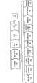
图1图示了根据本发明一个实施例的在设计和制作集成电路时的各种阶段。FIG. 1 illustrates various stages in designing and fabricating an integrated circuit according to one embodiment of the invention.
图2图示了根据本发明一个实施例的典型光学系统。Figure 2 illustrates a typical optical system according to one embodiment of the present invention.
图3图示了根据本发明一个实施例的等聚焦图案。Figure 3 illustrates an isofocus pattern according to one embodiment of the invention.
图4图示了根据本发明一个实施例的等聚焦图案为何对聚焦变化基本上不敏感。Figure 4 illustrates how an isofocus pattern is substantially insensitive to focus variations according to one embodiment of the invention.
图5图示了根据本发明一个实施例的剂量对等聚焦图案的影响。Figure 5 illustrates the effect of dose on the isofocus pattern according to one embodiment of the invention.
图6呈现了对根据本发明一个实施例的用于确定光学阈值的过程进行图示的流程图。FIG. 6 presents a flowchart illustrating a process for determining an optical threshold according to one embodiment of the invention.
图7呈现了对根据本发明一个实施例的用于确定抗蚀剂偏置的过程进行图示的流程图。FIG. 7 presents a flowchart illustrating a process for determining a resist bias according to one embodiment of the present invention.
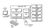
图8图示了根据本发明一个实施例的计算机系统。Figure 8 illustrates a computer system according to one embodiment of the present invention.
具体实施方式Detailed ways
呈现以下描述以使本领域技术人员能够实现和利用本发明,并且在特定应用及其要求的背景中提供该描述。本领域技术人员将容易清楚对公开的实施例的各种修改,并且这里限定的一般原理可以适用于其它实施例和应用而不脱离本发明的精神实质和范围。因此,本发明不限于所示实施例而是将被赋予以与这里公开的原理和特征一致的最广范围。The following description is presented to enable any person skilled in the art to make and use the invention, and is presented in the context of a particular application and its requirements. Various modifications to the disclosed embodiments will be readily apparent to those skilled in the art, and the general principles defined herein may be applied to other embodiments and applications without departing from the spirit and scope of the invention. Thus, the present invention is not limited to the embodiments shown but is to be accorded the widest scope consistent with the principles and features disclosed herein.
集成电路(IC)设计流程Integrated Circuit (IC) Design Flow
图1图示了根据本发明一个实施例的在设计和制作集成电路时的各种阶段。FIG. 1 illustrates various stages in designing and fabricating an integrated circuit according to one embodiment of the invention.
该过程通常从使用EDA过程(步骤110)来实现的产品想法(步骤100)开始。一旦设计定稿,通常流片(tap-out)(事件140)该设计,并且该设计经过制作工艺(步骤150)以及封装和组装工艺(步骤160)以产生成品芯片(结果170)。The process typically begins with a product idea (step 100 ) that is implemented using the EDA process (step 110 ). Once the design is finalized, the design is typically tap-out (event 140) and the design passes through the fabrication process (step 150) and the packaging and assembly process (step 160) to produce a finished chip (result 170).
EDA过程(步骤110)包括下文仅出于示例目的而描述的而且并非用来限制本发明的步骤112-130。具体而言,实际集成电路设计可能要求设计者在与下述顺序不同的顺序中进行设计步骤。The EDA process (step 110) includes steps 112-130 which are described below for example purposes only and are not intended to limit the invention. Specifically, actual integrated circuit design may require the designer to perform the design steps in an order different from that described below.
系统设计(步骤112):在这一步骤中,设计者描述他们想要实施的功能。他们也可以进行假设(what-if)规划以精化功能、检验成本等。硬件-软件架构划分可以出现在这一阶段。可以在这一步骤使用的来自Synopsys公司的示例性EDA软件产品包括ModelArchitect、

逻辑设计和功能验证(步骤114):在这一阶段,编写用于系统中的模块的VHDL或者Verilog代码,并且检验该设计的功能准确性。具体而言,检验该设计以保证它产生正确输出。可以在这一步骤使用的来自Synopsys公司的示例性EDA软件产品包括


合成和测试设计(步骤116):VHDL/Verilog可以在这一阶段中转译成网表。可以针对目标技术优化网表,并且可以设计和实施测试以检验成品芯片。可以在这一步骤使用的来自Synopsys公司的示例性EDA软件产品包括DesignPhysical


网表验证(步骤118):在这一步骤中,检验网表与时序约束的相符性和与VHDL/Verilog源代码的对应性。可以在这一步骤使用的来自Synopsys公司的示例性EDA软件产品包括


设计规划(步骤120):这里,构造和分析用于芯片的整个平面图以便进行定时和顶层布线。可以在这一步骤使用的来自Synopsys公司的示例性EDA软件产品包括AstroTM和IC Compiler产品。Design Planning (step 120): Here, the entire floor plan for the chip is constructed and analyzed for timing and top-level routing. Exemplary EDA software products from Synopsys, Inc. that can be used at this step include the Astro™ and IC Compiler products.
物理实施(步骤122):在这一步骤出现布置(对电路元件的定位)和布线(对电路元件的连接)。可以在这一步骤使用的来自Synopsys公司的示例性EDA软件产品包括AstroTM和IC Compiler产品。Physical implementation (step 122): Placement (positioning of circuit elements) and routing (connection of circuit elements) occur at this step. Exemplary EDA software products from Synopsys, Inc. that can be used at this step include the Astro™ and IC Compiler products.
分析和提取(步骤124):在这一阶段,在晶体管级验证电路功能;这又允许假设的精化。可以在这一步骤使用的来自Synopsys公司的示例性EDA软件产品包括AstroRailTM、PrimeRail、
物理验证(步骤126):在这一步骤中,检验设计以保证制造、电问题、光刻问题和电路的正确性。可以在这一步骤使用的来自Synopsys公司的示例性EDA软件产品包括HerculesTM。Physical Verification (step 126): In this step, the design is verified for fabrication, electrical issues, photolithographic issues, and correctness of the circuitry. Exemplary EDA software products from Synopsys Corporation that can be used at this step include Hercules™ .
分辨率增强(步骤128):这一步骤涉及到对布局的几何形状操控以提高设计的可制造性。可以在这一步骤使用的来自Synopsys公司的示例性EDA软件产品包括Proteus/Progen、ProteusAF和PSMGen。Resolution Enhancement (step 128): This step involves geometric manipulation of the layout to improve the manufacturability of the design. Exemplary EDA software products from Synopsys, Inc. that can be used at this step include Proteus/Progen, ProteusAF, and PSMGen.
掩模数据预备(步骤130):这一步骤提供用于产生掩模以产生成品芯片的“流片”数据。可以在这一步骤使用的来自Synopsys公司的示例性EDA软件产品包括
工艺模型craft model
工艺模型对通常涉及到复杂的物理和化学互作用的一个或者多个半导体制造工艺的性能进行建模。通过将内核系数与经验数据拟合或者校准来确定工艺模型。通常通过将正在被建模的半导体制造工艺应用于一个或者多个测试布局来生成经验数据。例如,光刻工艺可以用来在晶片上印刷测试布局。接着,可以通过测量特征的关键尺度(CD)来获得经验数据。未校准的工艺模型然后可以与经验数据拟合以获得对光刻工艺进行建模的已校准的工艺模型。A process model models the performance of one or more semiconductor manufacturing processes, often involving complex physical and chemical interactions. The process model is determined by fitting or calibrating the kernel coefficients to empirical data. Empirical data is typically generated by applying the semiconductor fabrication process being modeled to one or more test layouts. For example, photolithography processes can be used to print test layouts on the wafer. Next, empirical data can be obtained by measuring the critical dimension (CD) of the feature. The uncalibrated process model can then be fit to empirical data to obtain a calibrated process model that models the lithographic process.
一旦确定工艺模型,它可以在设计和制造半导体芯片期间使用于诸多应用中。例如,工艺模型通常用来支持光学邻近校正(OPC)和分辨率增强技术(RET)。这些模型可以在流片流程期间在合理期限内允许全芯片的数据库操控。Once a process model is determined, it can be used in many applications during the design and manufacture of semiconductor chips. For example, process models are often used to support Optical Proximity Correction (OPC) and Resolution Enhancement Technology (RET). These models allow full-chip database manipulation within reasonable deadlines during the tape-out process.
未校准的工艺模型通常包括与参数和/或系数关联的分量。在校准期间,参数和/或系数可以令人满意地与经验数据拟合以获得最终工艺模型。工艺模型中的一个分量通常是设计成对特定物理效果进行建模的数学表达式。例如,可以将工艺模型表示为
通常不可能校准系数值使得预测的数据与经验数据精确地匹配。即使精确拟合是可用的,但是可能并不需要这样,因为所得工艺模型可能没有恰当地内插和/或外插。通常,统计拟合技术用来确定参数和/或系数从而使经验数据与预测的数据之间的误差最小。在一个实施例中,系统可以使用最小平方拟合技术以确定参数和/或系数值。It is usually not possible to calibrate the coefficient values so that the predicted data exactly matches the empirical data. Even if an exact fit is available, it may not be required since the resulting process model may not be interpolated and/or extrapolated properly. Typically, statistical fitting techniques are used to determine parameters and/or coefficients to minimize errors between empirical and predicted data. In one embodiment, the system may use a least squares fitting technique to determine parameter and/or coefficient values.
如果工艺模型适当地内插和外插,即如果工艺模型在它应用于与在拟合过程期间使用的布局不同的布局时生成准确结果,则认为它是稳健的。一般而言,工艺模型使用越少的建模函数或者内核,它就越稳健。然而,使用更少内核可能降低工艺模型的准确性。因此,通常在工艺模型的稳健性与准确性之间存在权衡。A process model is considered robust if it is properly interpolated and extrapolated, ie if it produces accurate results when it is applied to a layout different from that used during the fitting process. In general, the fewer modeling functions or kernels a process model uses, the more robust it will be. However, using fewer cores may reduce the accuracy of the process model. Therefore, there is usually a trade-off between the robustness and accuracy of the process model.
光刻工艺模型Lithography Process Model
可以使用统计建模和/或物理建模来确定工艺模型。统计建模技术通常使用具有与经验数据拟合的系数和/或参数的通用建模函数。注意统计模型所用函数通常并不基于下层物理过程的工作;它们代之以是可以用来拟合任一种经验数据的有普适性的建模函数。The process model can be determined using statistical modeling and/or physical modeling. Statistical modeling techniques typically use generic modeling functions with coefficients and/or parameters fitted to empirical data. Note that the functions used in statistical models are usually not based on the workings of the underlying physical processes; instead they are general modeling functions that can be used to fit any kind of empirical data.
与统计建模对照,物理建模试图对下层物理过程进行建模。例如,用于光刻工艺的物理模型通常包括光学模型和抗蚀剂模型。光学模型可以对用来使抗蚀剂曝光的光学系统进行建模,而抗蚀剂模型可以对抗蚀剂在曝光于辐射时的性能进行建模。In contrast to statistical modeling, physical modeling attempts to model the underlying physical processes. For example, a physical model for a photolithography process usually includes an optical model and a resist model. The optical model can model the optical system used to expose the resist, and the resist model can model the behavior of the resist when exposed to radiation.
光学模型optical model
光刻工艺模型中的光学模型通常基于对部分相干光学系统的性能进行建模的霍普金斯(Hopkins)模型。Optical models in lithographic process models are usually based on the Hopkins model that models the behavior of partially coherent optical systems.
图2图示了根据本发明一个实施例的典型光学系统。Figure 2 illustrates a typical optical system according to one embodiment of the present invention.
来自源202的辐射可以由聚光器204准直。准直光然后可以通过掩模206、孔208、透镜体210并且在晶片212上形成图像。Radiation from source 202 may be collimated by
可以使用以下表达式来描述霍普金斯模型:The Hopkins model can be described using the following expression:
其中I(x,y)是在晶片上的点(x,y)的光学密度,L(x,y;x′,y′)是光源和掩模的集总模型,L*是L的复共轭,而J(x′,y′;x″,y″)对光在掩模上的两点之间的相干性进行建模。集总模型(L)实质上将掩模视为光源阵列。具体而言,L(x,y;x′,y′)对掩模上作为点源的点(x′,y′)进行建模,而J(x′,y′;x″,y″)对从掩模上的点(x′,y′)和(x″,y″)发散的光之间的相干性进行建模。可以将集总模型(L)表示为掩模与源之间的卷积。例如,可以使用掩模模型和源模型将集总模型表示如下:where I(x,y) is the optical density at point (x,y) on the wafer, L(x,y; x′,y′) is the lumped model of the light source and mask, and L* is the complex of L conjugate, while J(x', y';x",y") models the coherence of light between two points on the mask. The lumped model (L) essentially treats the mask as an array of light sources. Specifically, L(x, y; x′, y′) models a point (x′, y′) on the mask as a point source, while J(x′, y′; x″, y″ ) models the coherence between light emanating from points (x', y') and (x", y") on the mask. The lumped model (L) can be expressed as a convolution between the mask and the source. For example, a lumped model can be expressed using a mask model and a source model as follows:
其中M(x′,y′)对掩模进行建模,而K(x,y;x′,y′)对源进行建模。where M(x', y') models the mask and K(x, y; x', y') models the source.
霍普金斯模型可以用来确定对光学系统进行建模的、称为传输交叉系数(TCC)矩阵的4D(四维)矩阵。然后可以使用成组正交2D(二维)内核来表示TCC矩阵。可以使用TCC矩阵的本征函数来确定该组正交内核。可以通过将该组2D内核与掩模卷积来确定晶片上的特征。可以在Alfred Kwok-Kit Wong于2005年在SPIE-International Society for Optical Engine发表的Optical Imagingin Projection Microlithography和Grant R.Fowles于1989年由Dover出版社出版的Introduction to Modern Optics第2版中找到关于光刻和工艺建模的主要信息。The Hopkins model can be used to determine a 4D (four-dimensional) matrix called the Transmission Cross Coefficient (TCC) matrix that models the optical system. The TCC matrix can then be represented using sets of orthogonal 2D (two-dimensional) kernels. The set of orthogonal kernels can be determined using the eigenfunctions of the TCC matrix. Features on the wafer can be determined by convolving the set of 2D kernels with the mask. Information about lithography can be found in Alfred Kwok-Kit Wong, SPIE-International Society for Optical Engine, Optical Imaging Projection Microlithography, 2005, and Grant R. Fowles, Introduction to Modern Optics, 2nd Edition, Dover Press, 1989 and key information for process modeling.
在一个实施例中,系统可以使用称为泽尔尼克多项式的成组正交函数以表示光学系统。泽尔尼克多项式由形式与在光学系统中经常观测到的像差类型相同的项组成。例如,一个泽尔尼克多项式可以与散焦关联,而另一泽尔尼克多项式可以与倾斜关联,等等。可以使用表达式
仅出于示例和描述的目的已经呈现对光刻工艺模型的前文描述。本意并非让它们穷举本发明或者使本发明限于公开的形式。因而,本领域技术人员将清楚许多修改和变化。The foregoing description of the lithography process model has been presented for purposes of illustration and description only. They are not intended to be exhaustive or to limit the invention to the form disclosed. Thus, many modifications and changes will be apparent to those skilled in the art.
抗蚀剂模型resist model
随着特征尺寸变得更小,工艺模型的准确性变得越来越关键。一般而言,物理模型通常优于统计模型,因为物理模型往往比统计模型更准确和稳健。常规光刻模型使用统计建模方式以对光学系统进行建模,但是它们使用统计建模方式以对抗蚀剂的性能进行建模。具体而言,常规建模技术通常通过移动“光学图像”或者对可变图像质量有不同响应来改变模型中的抗蚀剂参数。随着集成密度增加,抗蚀剂模型的不准确性会变得可观。因此,需要提高抗蚀剂模型的准确性。As feature sizes get smaller, the accuracy of the process model becomes more and more critical. In general, physical models are often preferred over statistical models because physical models tend to be more accurate and robust than statistical models. Conventional lithography models use statistical modeling to model optical systems, but they use statistical modeling to model the behavior of resists. Specifically, conventional modeling techniques typically vary the resist parameters in the model by shifting the "optical image" or responding differently to variable image quality. The inaccuracies of the resist model can become appreciable as the integration density increases. Therefore, there is a need to improve the accuracy of resist models.
在工艺模型校准期间,未校准的工艺模型与经验数据拟合。通过测量晶片上的特征的关键尺度来获得用于光刻工艺模型的经验数据。然而,注意,晶片上的特征的关键尺度结合光学系统的性能以及抗蚀剂的性能。换而言之,通常用于对光刻工艺进行建模的经验数据没有将光学效果与抗蚀剂效果分离。如果没有对抗蚀剂效果具体地进行捕获的经验数据,则即使并非不可能也很难对抗蚀剂效果准确地进行建模。During process model calibration, an uncalibrated process model is fitted to empirical data. Empirical data for the lithography process model is obtained by measuring critical dimensions of features on the wafer. Note, however, that the critical dimensions of the features on the wafer combine the performance of the optical system as well as the performance of the resist. In other words, empirical data commonly used to model lithographic processes does not separate optical effects from resist effects. Accurately modeling resist effects is difficult, if not impossible, without empirical data that specifically captures resist effects.
光学阈值和抗蚀剂偏置是可以用于为抗蚀剂创建准确物理模型的两个参数。可以将光学阈值限定为如下强度水平,该强度水平造成抗蚀剂材料将它的特性改变如下数量,该数量足以造成在晶片上印刷图案。可以将抗蚀剂偏置限定为特征的关键尺度在晶片的表面已经曝光于辐射之后的光刻工艺中所用化学和物理过程期间的改变。Optical threshold and resist bias are two parameters that can be used to create an accurate physical model for the resist. The optical threshold can be defined as the level of intensity that causes the resist material to change its properties by an amount sufficient to cause a pattern to be printed on the wafer. Resist bias can be defined as a change in the critical dimensions of a feature during the chemical and physical processes used in the photolithography process after the surface of the wafer has been exposed to radiation.
注意光学模型通常很准确;因此,可以高准确度地确定晶片的表面上任一点的空间图像强度。然而由于光学阈值未知,所以不能高准确度地确定如下抗蚀剂的区域,该抗蚀剂的特性已经改变得足以使图案将印刷于晶片的表面上。Note that the optical model is generally very accurate; therefore, the aerial image intensity at any point on the surface of the wafer can be determined with high accuracy. However, since the optical threshold is unknown, it is not possible to determine with high accuracy the areas of the resist whose properties have changed enough that the pattern will be printed on the surface of the wafer.
本发明的一个实施例利用以下认识:如果知道光学阈值,则可以通过计算在晶片的表面上测量的关键尺度与如下“光学关键尺度”之差来确定抗蚀剂偏置,这些光学关键尺度可以限定为在将抗蚀剂曝光之后、但是在更多物理和化学工艺应用于晶片的表面之前存在的理论关键尺度。One embodiment of the invention exploits the realization that, if the optical threshold is known, resist bias can be determined by calculating the difference between critical dimensions measured on the surface of the wafer and "optical critical dimensions" that can be Defined as the theoretical critical dimensions that exist after the resist is exposed, but before more physical and chemical processes are applied to the surface of the wafer.
注意,直接地测量光学阈值不切实际。然而,本发明的一个实施例通过确定等聚焦图案在不同聚焦条件之下的空间图像强度来确定光学阈值。具体而言,该实施例利用以下认识:(1)对于固定剂量,如果空间图像为等聚焦,则对应印刷图案将也是等聚焦,并且反之亦然;以及(2)在等聚焦图案的边缘的空间图像强度在聚焦条件改变时保持基本上相同。因此,如果可以标识等聚焦图案,则可以通过确定空间图像强度曲线在不同聚焦条件之下的“交点”来确定光学阈值。Note that it is impractical to directly measure the optical threshold. However, one embodiment of the invention determines the optical threshold by determining the spatial image intensity of the isofocus pattern under different focus conditions. Specifically, this embodiment exploits the realization that (1) for a fixed dose, if the aerial image is isofocus, the corresponding printed pattern will also be isofocus, and vice versa; and (2) at the edge of the isofocus pattern The spatial image intensity remains substantially the same as the focus conditions change. Thus, if an isofocus pattern can be identified, the optical threshold can be determined by determining the "intersection" of the spatial image intensity curves under different focus conditions.
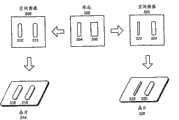
图3图示了根据本发明一个实施例的等聚焦图案。注意,图3中所示图案仅用于示例目的而并非为了代表实际光刻工艺中所用图案。Figure 3 illustrates an isofocus pattern according to one embodiment of the invention. Note that the patterns shown in FIG. 3 are for illustrative purposes only and are not intended to represent patterns used in actual photolithography processes.
布局302包括图案304和306。在特定聚焦条件之下将布局302曝光获得包括空间图像图案310和312的空间图像308。对于亮场掩模,空间图像图案通常对应于晶片上的如下区域,空间图像强度在该区域中小于光学阈值。另一方面,对于暗场掩模,空间图像图案通常对应于晶片上的如下区域,空间图像强度在该区域中大于光学阈值。在进一步处理之后,可以在晶片314上印刷图案316和318。Layout 302 includes
改变聚焦条件通常改变空间图像图案和所得印刷图案的关键尺度。例如,可以通过在与产生空间图像308的聚焦条件不同的聚焦条件之下将布局302曝光来获得空间图像320。即使由相同布局图案生成空间图像图案310和322,空间图像图案310和322的关键尺度仍然完全不同,并且分别在晶片314和326上的印刷图案316和328的关键尺度也完全不同。Changing the focus conditions generally changes the key dimensions of the spatial image pattern and the resulting printed pattern. For example,
等聚焦图案对聚焦条件的变化基本上不敏感。例如,图案306是等聚焦图案,因为对应空间图像图案312和324即使在不同聚焦条件之下生成它们仍然基本上彼此相似。另外,由于空间图像图案基本上相似,所以晶片上的所得印刷图案也有望基本上相似,并且反之亦然。例如,印刷图案318和330也基本上彼此相似。Isofocus patterns are substantially insensitive to changes in focus conditions. For example,
注意,等聚焦图案的关键尺度可以与布局上的对应图案的关键尺度匹配或者可以不匹配。例如,即使图案306是等聚焦图案,空间图像图案312和印刷图案318仍然比布局上的图案306更细。Note that the key dimensions of the isofocus pattern may or may not match those of the corresponding pattern on the layout. For example, even though
图4图示了根据本发明一个实施例的等聚焦图案为何对聚焦变化基本上不敏感。Figure 4 illustrates how an isofocus pattern is substantially insensitive to focus variations according to one embodiment of the invention.
线402、404、406和408可以是布局的部分。不失一般性,可以假设使用正性光刻胶和亮场掩模将布局曝光。因此,如果空间图像强度小于光学阈值,则将印刷图案。具体而言,光学系统模型可以用来确定在晶片上的一个位置的空间图像强度。接着,可以比较空间图像强度与光学阈值以确定图案是否将印刷于该位置。
空间图像强度绘图400图示了空间图像强度随着线404的宽度的变化。将清楚的是,恒定光学阈值可以由绘图400中的水平线(为求简洁而未示出)代表。在绘图400中,光学阈值线将与空间图像强度曲线相交于两点,例如光学阈值线可以与曲线418相交于点412和420。在这两个交点之间的距离410对应于用于线404的印刷线宽。如果认为这一线宽是关键尺度,则距离410将是用于线404的关键尺度测量。Aerial
注意,空间强度曲线通常在不同聚焦条件之下不同。例如,空间强度曲线414、416和418代表在不同聚焦条件之下的空间图像强度。Note that the spatial intensity curves generally differ under different focusing conditions. For example, spatial intensity curves 414, 416, and 418 represent spatial image intensity under different focus conditions.
本发明的一个实施例利用以下认识:如果具有等聚焦图案,则用于不同聚焦条件的空间强度曲线应当相交于同一点,并且这一点应当在光学阈值线上。换而言之,可以通过确定与不同聚焦条件对应的空间强度曲线的交点来确定光学阈值。例如在绘图400中,如果线404是等聚焦图案,则与交点412关联的空间强度值将等于光学阈值。One embodiment of the invention exploits the insight that if one has an isofocus pattern, the spatial intensity curves for different focus conditions should intersect at the same point, and this point should be on the optical threshold line. In other words, the optical threshold can be determined by determining the intersection points of the spatial intensity curves corresponding to different focusing conditions. For example, in
注意在实践中,图案可能并非理想地等聚焦,并且即使图案理想地等聚焦,不同空间强度曲线仍然可能并未精确地相交于同一点。然而,曲线的交点将最可能彼此仍然很近。在这样的情形中,可以通过使用与成组交点关联的光学阈值的值来确定光学阈值。例如,可以通过选择交点之一、然后确定与所选交点关联的空间图像强度值来确定光学阈值。取而代之,可以通过确定与成组交点关联的光学阈值的值的统计量如平均值来确定光学阈值。Note that in practice, the patterns may not be ideally isofocused, and even if the patterns were ideally isofocused, the different spatial intensity curves still may not intersect exactly at the same point. However, the intersection points of the curves will most likely still be close to each other. In such cases, the optical threshold may be determined by using the value of the optical threshold associated with the set of intersection points. For example, the optical threshold may be determined by selecting one of the intersection points and then determining the spatial image intensity value associated with the selected intersection point. Instead, the optical threshold may be determined by determining a statistic, such as an average, of the values of the optical threshold associated with groups of intersection points.
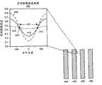
图5图示了根据本发明一个实施例的剂量对等聚焦图案的影响。Figure 5 illustrates the effect of dose on the isofocus pattern according to one embodiment of the invention.
等聚焦图案通常在特定剂量(该剂量是用于曝光的辐射能量的数量)表现等聚焦性能。然而,如果改变剂量,则图案可能并未表现等聚焦性能。绘图500中的各曲线绘出了对于特定剂量值随聚焦变化的图案的关键尺度(例如抗蚀剂特征宽度)。注意,等聚焦性能在绘图中将自身展现为基本上水平线。例如,曲线504对应于图案表现等聚焦性能时的剂量。然而在更低或者更高剂量下,图案可以分别生成不与等聚焦性能对应的曲线502和506,因为曲线502和506不是基本上水平线。An isofocus pattern typically exhibits isofocus properties at a specific dose (the dose being the amount of radiant energy used for exposure). However, if the dose is varied, the pattern may not exhibit isofocus properties. Each curve in plot 500 plots a key dimension of the pattern (eg, resist feature width) as a function of focus for a particular dose value. Note that the isofocus properties manifest themselves as substantially horizontal lines in the plot. For example,
基于上述讨论,以下章节描述用于确定光学阈值和抗蚀剂偏置的系统和技术。Based on the above discussion, the following sections describe systems and techniques for determining optical threshold and resist bias.
用于确定光学阈值的过程Process for Determining Optical Threshold
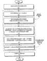
图6呈现了对根据本发明一个实施例的用于确定光学阈值的过程进行图示的流程图。FIG. 6 presents a flowchart illustrating a process for determining an optical threshold according to one embodiment of the invention.
该过程可以始于接收包括待印刷的图案的布局(步骤602)。The process may begin by receiving a layout including a pattern to be printed (step 602).
接着,系统可以确定等聚焦图案(步骤604)。具体而言,系统可以在不同聚焦条件之下印刷布局(步骤606)。接着,系统可以确定印刷图案,使得印刷图案的关键尺度对聚焦变化基本上不敏感(步骤608)。Next, the system can determine an isofocus pattern (step 604). Specifically, the system may print the layout under different focus conditions (step 606). Next, the system can determine the printed pattern such that critical dimensions of the printed pattern are substantially insensitive to focus changes (step 608).
可以具体地设计布局中的图案以标识等聚焦图案。例如,布局可以具有线宽和间距可变的线和空间图案。通过印刷线宽和间距不同的线和空间图案,可以标识产生等聚焦线和空间图案的线宽值和间距值。The patterns in the layout can be specifically designed to identify isofocal patterns. For example, a layout may have a line and space pattern with variable line width and spacing. By printing line and space patterns with different line widths and spaces, it is possible to identify the line width and space values that produce isofocal line and space patterns.
系统然后可以使用等聚焦图案以确定光学阈值的值(步骤610)。具体而言,系统可以通过将布局与多个光学模型卷积来确定多个空间图像强度值,其中多个光学模型对不同聚焦条件之下的光刻工艺的光学系统进行建模(步骤612)。接着,系统可以确定与等聚焦图案邻近的第一位置,空间图像强度值在该第一位置对聚焦变化基本上不敏感(步骤614)。系统然后可以使用在第一位置的空间图像强度值来确定光学阈值的值(步骤616)。接着,系统可以存储光学阈值的值(步骤618)。The system can then use the isofocus pattern to determine the value of the optical threshold (step 610). Specifically, the system can determine multiple spatial image intensity values by convolving the layout with multiple optical models that model the optical system of the lithography process under different focusing conditions (step 612) . Next, the system may determine a first location adjacent to the isofocus pattern at which spatial image intensity values are substantially insensitive to focus changes (step 614). The system may then use the aerial image intensity value at the first location to determine a value for the optical threshold (step 616). Next, the system may store the value of the optical threshold (step 618).
可以在布局中的任何评估点进行布局与工艺模型的卷积。评估点可以是预测光刻工艺的效果时关注的布局中的任何位置。例如,评估点可以位于线端上,并且可以关注于确定线端是否将恰当地印刷。The convolution of the layout with the process model can be done at any evaluation point in the layout. An evaluation point can be any location in the layout that is of interest when predicting the effects of the lithographic process. For example, an evaluation point may be located on a line end, and may focus on determining whether the line end will print properly.
通常通过在评估点将代表布局的2D函数与工艺模型卷积来进行卷积。注意,工艺模型通常具有范围,因此卷积运算通常无需系统将整个布局与工艺模型卷积;系统代之以仅需对布局落入该范围内的部分进行卷积。Convolution is typically performed by convolving a 2D function representing the layout with the process model at the evaluation point. Note that process models usually have a range, so convolution operations generally do not require the system to convolve the entire layout with the process model; instead the system only needs to convolve the portion of the layout that falls within the range.
卷积的值然后可以用来确定光刻工艺在评估点的效果。例如,系统可以在布局中的多个评估点将布局与工艺模型卷积并且比较卷积值与阈值以确定代表印刷图案形状的轮廓。The value of the convolution can then be used to determine the effect of the photolithography process at the point of evaluation. For example, the system may convolve the layout with the process model at multiple evaluation points in the layout and compare the convolution values to a threshold to determine a contour representing the shape of the printed pattern.
用于确定抗蚀剂偏置的过程Process for Determining Resist Bias
图7呈现了对根据本发明一个实施例的用于确定抗蚀剂偏置的过程进行图示的流程图。FIG. 7 presents a flowchart illustrating a process for determining a resist bias according to one embodiment of the present invention.
该过程可以开始于接收布局(步骤702)。The process may begin by receiving a layout (step 702).
接着,系统可以通过测量在晶片上印刷的等聚焦图案的关键尺度来确定抗蚀剂关键尺度值,其中等聚焦图案的关键尺度对聚焦变化基本上不敏感(步骤704)。Next, the system may determine resist critical dimension values by measuring critical dimensions of isofocus patterns printed on the wafer that are substantially insensitive to focus variations (step 704).
如上文说明的那样,系统可以通过以下操作来标识布局中的等聚焦图案:在不同聚焦条件之下印刷布局以获得成组晶片上的印刷图案,测量印刷图案的关键尺度,以及确定其关键尺度测量对聚焦变化基本上不敏感的图案。As explained above, the system can identify isofocus patterns in a layout by printing the layout under different focus conditions to obtain printed patterns on groups of wafers, measuring the critical dimensions of the printed patterns, and determining their critical dimensions Measure patterns that are substantially insensitive to focus changes.
系统然后可以确定光学关键尺度值(步骤706)。具体而言,系统可以通过将布局与多个光学模型卷积来确定与等聚焦图案邻近的多个空间图像强度值,其中多个光学模型对不同聚焦条件之下的光刻工艺的光学系统进行建模(步骤708)。接着,系统可以确定与等聚焦图案邻近的第一位置,其中空间图像强度值在该第一位置对聚焦变化基本上不敏感(步骤710)。系统然后可以通过确定在第一位置与参考位置之间的距离来确定光学关键尺度值(步骤712)。The system can then determine optical key dimension values (step 706). Specifically, the system can determine multiple spatial image intensity values adjacent to an isofocus pattern by convolving the layout with multiple optical models that simulate the optical system of the lithography process under different focusing conditions. Modeling (step 708). Next, the system may determine a first location adjacent to the isofocus pattern where the spatial image intensity value is substantially insensitive to focus changes (step 710). The system may then determine optical key dimension values by determining the distance between the first location and the reference location (step 712).
参考位置一般可以是用来确定光学关键尺度的任何位置。例如,参考位置可以是图案的中心,例如线的中心。取而代之,参考位置可以是在图案的另一侧上的如下位置,空间图像强度值在该位置对聚焦变化基本上不敏感。例如,如果第一位置是图4中的点420,则参考位置可以在“0”位置或者在点412。The reference position may generally be any position used to determine the optical critical dimension. For example, the reference position may be the center of a pattern, such as the center of a line. Instead, the reference position may be a position on the other side of the pattern where the spatial image intensity value is substantially insensitive to focus changes. For example, if the first location is
将清楚的是,可能需要调节在第一位置与参考位置之间的距离以获得光学关键尺度值。例如,如果参考位置是点412,则在第一位置与参考位置之间的距离将是光学关键尺度值。另一方面,如果参考位置在“0”位置,假设“0”位置在线404的中心,则在第一位置与参考位置之间的距离可能需要翻倍以获得光学关键尺度值。It will be clear that it may be necessary to adjust the distance between the first position and the reference position to obtain the optical key dimension value. For example, if the reference location is
接着,系统可以通过抗蚀剂关键尺度值与光学关键尺度值之差来确定抗蚀剂偏置(步骤714)。系统然后可以存储抗蚀剂偏置(步骤716)。Next, the system can determine the resist bias from the difference between the resist critical dimension value and the optical critical dimension value (step 714). The system can then store the resist bias (step 716).
抗蚀剂偏置和/或光学阈值可以用来为光刻工艺确定光刻工艺模型。具体而言,抗蚀剂偏置和/或光学阈值可以用来为抗蚀剂确定物理模型。光刻工艺模型可以用来进行光学邻近校正或者预测晶片上的印刷图案的轮廓。The resist bias and/or optical threshold can be used to determine a lithography process model for the lithography process. In particular, resist bias and/or optical threshold can be used to determine a physical model for the resist. Lithographic process models can be used to perform optical proximity correction or to predict the profile of printed patterns on a wafer.
图8图示了根据本发明一个实施例的计算机系统。Figure 8 illustrates a computer system according to one embodiment of the present invention.
计算机系统802包括处理器804、存储器806和存储设备808。计算机系统802可以与显示器814、键盘810和指示设备812耦合。存储设备808可以存储布局816、工艺模型818、参数820、经验数据822和应用824。Computer system 802 includes
经验数据822可以包括在对布局816进行光刻工艺时在晶片的表面上印刷的特征的关键尺度测量。应用824可以包括如下指令,这些指令在由处理器804执行时使得计算机系统802实现用于确定光学阈值的方法和/或实现用于确定抗蚀剂偏置的方法。
在操作期间,计算机系统802可以在存储器806中加载应用824。接着,系统可以使用经验数据822以确定等聚焦图案和抗蚀剂关键尺度。系统然后可以使用布局816和工艺模型818以确定光学阈值和光学关键尺度。接着,系统可以确定抗蚀剂偏置。系统然后可以在存储设备808中存储计算的参数,比如光学阈值和抗蚀剂偏置。During operation, computer system 802 may load
系统然后可以使用光学阈值和抗蚀剂偏置来确定光刻工艺模型。系统可以通过在计算机可读存储介质中存储关联的参数和/或系数来在存储设备808上存储工艺模型。具体而言,在一个实施例中,系统可以通过存储参数、系数、内核标识符以及将参数和系数与它们的相应内核标识符关联的信息来存储工艺模型。内核标识符可以是标识内核的串,或者它可以是代表内核的表达式。接着,系统可以使用工艺模型以确定邻近校正或者预测印刷图案的轮廓。The system can then use the optical threshold and resist bias to determine a lithography process model. The system may store the process model on
结论in conclusion
在本具体实施方式中描述的数据结构和代码通常存储于计算机可读存储介质上,该介质可以是能够存储用于由计算机系统使用的代码和/或数据的任何设备或者介质。计算机可读存储介质包括但不限于易失性存储器、非易失性存储器、磁和光学存储设备(比如盘驱动器、磁带、CD(压缩盘)、DVD(数字多功能盘或者数字视频盘)或者现在已知或者以后开发的能够存储计算机可读介质的其它介质。The data structures and code described in this Detailed Description are typically stored on a computer readable storage medium, which may be any device or medium that can store code and/or data for use by a computer system. Computer-readable storage media include, but are not limited to, volatile memory, non-volatile memory, magnetic and optical storage devices such as disk drives, magnetic tape, CDs (compact disks), DVDs (digital versatile disks or digital video disks), or Other media capable of storing computer-readable media are now known or later developed.
可以将具体实施方式这一节中描述的方法和过程实施为能够存储于如上所述计算机可读存储介质中的代码和/或数据。当计算机系统读取和执行计算机可读存储介质上存储的代码和/或数据时,计算机系统实现作为数据结构和代码来体现的并且存储于计算机可读存储介质内的方法和过程。The methods and processes described in this section of the detailed description can be implemented as code and/or data that can be stored in a computer-readable storage medium as described above. When a computer system reads and executes the code and/or data stored on the computer-readable storage medium, the computer system implements the methods and processes embodied as data structures and code and stored within the computer-readable storage medium.
另外,可以在硬件模块中包括所述方法和过程。例如,硬件模块可以包括但不限于专用集成电路(ASIC)芯片、现场可编程门阵列(FPGA)和现在已知或者以后开发的其它可编程逻辑器件。当激活硬件模块时,硬件模块实现硬件模块内包括的方法和过程。Additionally, the methods and procedures may be included in hardware modules. For example, hardware modules may include, but are not limited to, Application Specific Integrated Circuit (ASIC) chips, Field Programmable Gate Arrays (FPGA), and other programmable logic devices now known or later developed. When a hardware module is activated, the hardware module implements the methods and processes included within the hardware module.
仅出于示例和描述的目的已经呈现对本发明实施例的前文描述。本意并非让它们穷举本发明或者使本发明限于公开的形式。因而,本领域技术人员将清楚许多修改和变化。此外,本意并非让上述公开内容限制本发明。本发明的范围由所附权利要求限定。The foregoing descriptions of embodiments of the invention have been presented for purposes of illustration and description only. They are not intended to be exhaustive or to limit the invention to the form disclosed. Thus, many modifications and changes will be apparent to those skilled in the art. Furthermore, it is not intended that the above disclosure limit the present invention. The scope of the invention is defined by the appended claims.
Claims (20)
Translated fromChineseApplications Claiming Priority (3)
| Application Number | Priority Date | Filing Date | Title |
|---|---|---|---|
| US12/244,178 | 2008-10-02 | ||
| US12/244,178US8184897B2 (en) | 2008-10-02 | 2008-10-02 | Method and apparatus for determining an optical threshold and a resist bias |
| PCT/US2009/053447WO2010039338A1 (en) | 2008-10-02 | 2009-08-11 | Method and apparatus for determining an optical threshold and a resist bias |
Publications (2)
| Publication Number | Publication Date |
|---|---|
| CN101802829A CN101802829A (en) | 2010-08-11 |
| CN101802829Btrue CN101802829B (en) | 2013-08-28 |
Family
ID=42073804
Family Applications (1)
| Application Number | Title | Priority Date | Filing Date |
|---|---|---|---|
| CN2009800002748AActiveCN101802829B (en) | 2008-10-02 | 2009-08-11 | Method and apparatus for determining optical threshold and resist bias |
Country Status (4)
| Country | Link |
|---|---|
| US (1) | US8184897B2 (en) |
| CN (1) | CN101802829B (en) |
| TW (1) | TWI482039B (en) |
| WO (1) | WO2010039338A1 (en) |
Families Citing this family (2)
| Publication number | Priority date | Publication date | Assignee | Title |
|---|---|---|---|---|
| US8843875B2 (en)* | 2012-05-08 | 2014-09-23 | Kla-Tencor Corporation | Measurement model optimization based on parameter variations across a wafer |
| TWI877374B (en)* | 2020-06-05 | 2025-03-21 | 美商新思科技股份有限公司 | Method and system of calibrating stochastic signals in compact modeling |
Citations (4)
| Publication number | Priority date | Publication date | Assignee | Title |
|---|---|---|---|---|
| US4890239A (en)* | 1987-10-20 | 1989-12-26 | Shipley Company, Inc. | Lithographic process analysis and control system |
| US20070032896A1 (en)* | 2005-08-05 | 2007-02-08 | Brion Technologies, Inc. | Method for lithography model calibration |
| US7266800B2 (en)* | 2004-06-04 | 2007-09-04 | Invarium, Inc. | Method and system for designing manufacturable patterns that account for the pattern- and position-dependent nature of patterning processes |
| US20080044739A1 (en)* | 2006-08-17 | 2008-02-21 | Toshiba America Electronic Components, Inc. | Correction Of Resist Critical Dimension Variations In Lithography Processes |
Family Cites Families (4)
| Publication number | Priority date | Publication date | Assignee | Title |
|---|---|---|---|---|
| KR20040032679A (en)* | 2002-10-10 | 2004-04-17 | 엘지전자 주식회사 | Method for controlling focus bias in optical disc driver |
| JP4351928B2 (en)* | 2004-02-23 | 2009-10-28 | 株式会社東芝 | Mask data correction method, photomask manufacturing method, and mask data correction program |
| KR100899359B1 (en)* | 2005-04-12 | 2009-05-27 | 에이에스엠엘 마스크툴즈 비.브이. | A method, program product and apparatus for performing double exposure lithography |
| US7707539B2 (en)* | 2007-09-28 | 2010-04-27 | Synopsys, Inc. | Facilitating process model accuracy by modeling mask corner rounding effects |
- 2008
- 2008-10-02USUS12/244,178patent/US8184897B2/enactiveActive
- 2009
- 2009-08-04TWTW098126255Apatent/TWI482039B/enactive
- 2009-08-11WOPCT/US2009/053447patent/WO2010039338A1/enactiveApplication Filing
- 2009-08-11CNCN2009800002748Apatent/CN101802829B/enactiveActive
Patent Citations (4)
| Publication number | Priority date | Publication date | Assignee | Title |
|---|---|---|---|---|
| US4890239A (en)* | 1987-10-20 | 1989-12-26 | Shipley Company, Inc. | Lithographic process analysis and control system |
| US7266800B2 (en)* | 2004-06-04 | 2007-09-04 | Invarium, Inc. | Method and system for designing manufacturable patterns that account for the pattern- and position-dependent nature of patterning processes |
| US20070032896A1 (en)* | 2005-08-05 | 2007-02-08 | Brion Technologies, Inc. | Method for lithography model calibration |
| US20080044739A1 (en)* | 2006-08-17 | 2008-02-21 | Toshiba America Electronic Components, Inc. | Correction Of Resist Critical Dimension Variations In Lithography Processes |
Also Published As
| Publication number | Publication date |
|---|---|
| TW201019150A (en) | 2010-05-16 |
| US20100086196A1 (en) | 2010-04-08 |
| WO2010039338A1 (en) | 2010-04-08 |
| TWI482039B (en) | 2015-04-21 |
| CN101802829A (en) | 2010-08-11 |
| US8184897B2 (en) | 2012-05-22 |
Similar Documents
| Publication | Publication Date | Title |
|---|---|---|
| CN101675389B (en) | Determination of a process model for modeling the effect of CAR/PEB on photoresist profile | |
| US7853919B2 (en) | Modeling mask corner rounding effects using multiple mask layers | |
| US8196068B2 (en) | Modeling critical-dimension (CD) scanning-electron-microscopy (CD-SEM) CD extraction | |
| US8181128B2 (en) | Method and apparatus for determining a photolithography process model which models the influence of topography variations | |
| US8812145B2 (en) | Modeling mask errors using aerial image sensitivity | |
| US7966582B2 (en) | Method and apparatus for modeling long-range EUVL flare | |
| US20170220723A1 (en) | 3d resist profile aware resolution enhancement techniques | |
| EP2297609B1 (en) | Method and apparatus for determining the effect of process variations | |
| US9679086B2 (en) | Method and apparatus for process window modeling | |
| US8355807B2 (en) | Method and apparatus for using aerial image sensitivity to model mask errors | |
| Park et al. | Automatic gate CD control for a full-chip-scale SRAM device | |
| US7454739B2 (en) | Method and apparatus for determining an accurate photolithography process model | |
| CN101802829B (en) | Method and apparatus for determining optical threshold and resist bias | |
| EP1862857B1 (en) | Method and apparatus for determining a process model for integrated circuit fabrication |
Legal Events
| Date | Code | Title | Description |
|---|---|---|---|
| C06 | Publication | ||
| PB01 | Publication | ||
| C10 | Entry into substantive examination | ||
| SE01 | Entry into force of request for substantive examination | ||
| C14 | Grant of patent or utility model | ||
| GR01 | Patent grant |