CN101801695A - Electromagnetic shock absorber for vehicle - Google Patents
Electromagnetic shock absorber for vehicleDownload PDFInfo
- Publication number
- CN101801695A CN101801695ACN200880107945ACN200880107945ACN101801695ACN 101801695 ACN101801695 ACN 101801695ACN 200880107945 ACN200880107945 ACN 200880107945ACN 200880107945 ACN200880107945 ACN 200880107945ACN 101801695 ACN101801695 ACN 101801695A
- Authority
- CN
- China
- Prior art keywords
- side unit
- screw
- sprung
- unsprung
- range
- Prior art date
- Legal status (The legal status is an assumption and is not a legal conclusion. Google has not performed a legal analysis and makes no representation as to the accuracy of the status listed.)
- Granted
Links
Images


Classifications
- B—PERFORMING OPERATIONS; TRANSPORTING
- B60—VEHICLES IN GENERAL
- B60G—VEHICLE SUSPENSION ARRANGEMENTS
- B60G15/00—Resilient suspensions characterised by arrangement, location or type of combined spring and vibration damper, e.g. telescopic type
- B60G15/08—Resilient suspensions characterised by arrangement, location or type of combined spring and vibration damper, e.g. telescopic type having fluid spring
- B60G15/10—Resilient suspensions characterised by arrangement, location or type of combined spring and vibration damper, e.g. telescopic type having fluid spring and mechanical damper or dynamic damper
- B—PERFORMING OPERATIONS; TRANSPORTING
- B60—VEHICLES IN GENERAL
- B60G—VEHICLE SUSPENSION ARRANGEMENTS
- B60G13/00—Resilient suspensions characterised by arrangement, location or type of vibration dampers
- B60G13/02—Resilient suspensions characterised by arrangement, location or type of vibration dampers having dampers dissipating energy, e.g. frictionally
- B—PERFORMING OPERATIONS; TRANSPORTING
- B60—VEHICLES IN GENERAL
- B60G—VEHICLE SUSPENSION ARRANGEMENTS
- B60G15/00—Resilient suspensions characterised by arrangement, location or type of combined spring and vibration damper, e.g. telescopic type
- B60G15/02—Resilient suspensions characterised by arrangement, location or type of combined spring and vibration damper, e.g. telescopic type having mechanical spring
- B60G15/06—Resilient suspensions characterised by arrangement, location or type of combined spring and vibration damper, e.g. telescopic type having mechanical spring and fluid damper
- B60G15/062—Resilient suspensions characterised by arrangement, location or type of combined spring and vibration damper, e.g. telescopic type having mechanical spring and fluid damper the spring being arranged around the damper
- B60G15/065—Resilient suspensions characterised by arrangement, location or type of combined spring and vibration damper, e.g. telescopic type having mechanical spring and fluid damper the spring being arranged around the damper characterised by the use of a combination of springs
- B—PERFORMING OPERATIONS; TRANSPORTING
- B60—VEHICLES IN GENERAL
- B60G—VEHICLE SUSPENSION ARRANGEMENTS
- B60G17/00—Resilient suspensions having means for adjusting the spring or vibration-damper characteristics, for regulating the distance between a supporting surface and a sprung part of vehicle or for locking suspension during use to meet varying vehicular or surface conditions, e.g. due to speed or load
- B60G17/02—Spring characteristics, e.g. mechanical springs and mechanical adjusting means
- B—PERFORMING OPERATIONS; TRANSPORTING
- B60—VEHICLES IN GENERAL
- B60G—VEHICLE SUSPENSION ARRANGEMENTS
- B60G2200/00—Indexing codes relating to suspension types
- B60G2200/10—Independent suspensions
- B60G2200/18—Multilink suspensions, e.g. elastokinematic arrangements
- B—PERFORMING OPERATIONS; TRANSPORTING
- B60—VEHICLES IN GENERAL
- B60G—VEHICLE SUSPENSION ARRANGEMENTS
- B60G2202/00—Indexing codes relating to the type of spring, damper or actuator
- B60G2202/10—Type of spring
- B60G2202/12—Wound spring
- B—PERFORMING OPERATIONS; TRANSPORTING
- B60—VEHICLES IN GENERAL
- B60G—VEHICLE SUSPENSION ARRANGEMENTS
- B60G2202/00—Indexing codes relating to the type of spring, damper or actuator
- B60G2202/20—Type of damper
- B60G2202/24—Fluid damper
- B—PERFORMING OPERATIONS; TRANSPORTING
- B60—VEHICLES IN GENERAL
- B60G—VEHICLE SUSPENSION ARRANGEMENTS
- B60G2202/00—Indexing codes relating to the type of spring, damper or actuator
- B60G2202/30—Spring/Damper and/or actuator Units
- B60G2202/31—Spring/Damper and/or actuator Units with the spring arranged around the damper, e.g. MacPherson strut
- B60G2202/314—The spring being a pneumatic spring
- B—PERFORMING OPERATIONS; TRANSPORTING
- B60—VEHICLES IN GENERAL
- B60G—VEHICLE SUSPENSION ARRANGEMENTS
- B60G2202/00—Indexing codes relating to the type of spring, damper or actuator
- B60G2202/40—Type of actuator
- B60G2202/42—Electric actuator
- B60G2202/422—Linear motor
- B—PERFORMING OPERATIONS; TRANSPORTING
- B60—VEHICLES IN GENERAL
- B60G—VEHICLE SUSPENSION ARRANGEMENTS
- B60G2204/00—Indexing codes related to suspensions per se or to auxiliary parts
- B60G2204/10—Mounting of suspension elements
- B60G2204/12—Mounting of springs or dampers
- B60G2204/128—Damper mount on vehicle body or chassis
- B—PERFORMING OPERATIONS; TRANSPORTING
- B60—VEHICLES IN GENERAL
- B60G—VEHICLE SUSPENSION ARRANGEMENTS
- B60G2204/00—Indexing codes related to suspensions per se or to auxiliary parts
- B60G2204/40—Auxiliary suspension parts; Adjustment of suspensions
- B60G2204/418—Bearings, e.g. ball or roller bearings
- B—PERFORMING OPERATIONS; TRANSPORTING
- B60—VEHICLES IN GENERAL
- B60G—VEHICLE SUSPENSION ARRANGEMENTS
- B60G2204/00—Indexing codes related to suspensions per se or to auxiliary parts
- B60G2204/40—Auxiliary suspension parts; Adjustment of suspensions
- B60G2204/419—Gears
- B—PERFORMING OPERATIONS; TRANSPORTING
- B60—VEHICLES IN GENERAL
- B60G—VEHICLE SUSPENSION ARRANGEMENTS
- B60G2204/00—Indexing codes related to suspensions per se or to auxiliary parts
- B60G2204/40—Auxiliary suspension parts; Adjustment of suspensions
- B60G2204/45—Stops limiting travel
- B60G2204/4502—Stops limiting travel using resilient buffer
- B—PERFORMING OPERATIONS; TRANSPORTING
- B60—VEHICLES IN GENERAL
- B60G—VEHICLE SUSPENSION ARRANGEMENTS
- B60G2400/00—Indexing codes relating to detected, measured or calculated conditions or factors
- B60G2400/25—Stroke; Height; Displacement
- B60G2400/252—Stroke; Height; Displacement vertical
- B—PERFORMING OPERATIONS; TRANSPORTING
- B60—VEHICLES IN GENERAL
- B60G—VEHICLE SUSPENSION ARRANGEMENTS
- B60G2500/00—Indexing codes relating to the regulated action or device
- B60G2500/30—Height or ground clearance
- F—MECHANICAL ENGINEERING; LIGHTING; HEATING; WEAPONS; BLASTING
- F16—ENGINEERING ELEMENTS AND UNITS; GENERAL MEASURES FOR PRODUCING AND MAINTAINING EFFECTIVE FUNCTIONING OF MACHINES OR INSTALLATIONS; THERMAL INSULATION IN GENERAL
- F16F—SPRINGS; SHOCK-ABSORBERS; MEANS FOR DAMPING VIBRATION
- F16F2232/00—Nature of movement
- F16F2232/06—Translation-to-rotary conversion
Landscapes
- Engineering & Computer Science (AREA)
- Mechanical Engineering (AREA)
- Vehicle Body Suspensions (AREA)
- Vibration Prevention Devices (AREA)
Abstract
Description
Translated fromChinese技术领域technical field
本发明涉及用于车辆的电磁减震器,其被构造为通过电磁电动机来产生对于簧上部分和簧下部分的相对移动的阻力。The present invention relates to an electromagnetic shock absorber for a vehicle, which is configured to generate resistance against relative movement of a sprung portion and an unsprung portion by an electromagnetic motor.
背景技术Background technique
在车辆领域,近来已经研发出一种电磁减震器(以下在合适的情况下简称为“减震器”),其被构造为基于由电磁电动机产生的力来产生对于簧上部分和簧下部分的相对移动的阻力。下述专利文献1中揭示的减震器是电磁减震器的一个示例。所揭示的减震器采用丝杠机构来将电磁电动机的转动力转换为对于簧上部分和簧下部分的相对移动的阻力。In the field of vehicles, an electromagnetic shock absorber (hereinafter simply referred to as a "shock absorber" where appropriate) has been developed recently, which is configured to generate a force for the sprung portion and the unsprung portion based on the force generated by the electromagnetic motor. The relative movement resistance of the parts. A shock absorber disclosed in
[专利文献1]JP-A-2006-143146[Patent Document 1] JP-A-2006-143146
发明内容Contents of the invention
(A)发明概述(A) Summary of the invention
一些采用丝杠机构的电磁减震器配备有如下构造的转动禁止机构。为了有效地将螺杆和螺母中一者的转动力转换为螺杆和螺母中另一者沿着其轴线方向的力,转动禁止机构被构造为禁止螺杆和螺母中的所述另一者绕轴线转动。当减震器伸缩时,绕轴线的转动力作用在转动禁止机构上。当减震器的伸或缩的移动突然停止时(例如在完全弹跳(bounding)和完全回弹(rebounding)时),作用在转动禁止机构上的转动力因螺杆和螺母中一者的惯性等原因而趋于变得相对较大。因为采用丝杠机构的电磁减震器仍然处于研发阶段,减震器存在诸如作用在转动禁止机构上的较大转动力之类的各种问题,由此存在很大的空间来改进减震器的实用性。着眼于以上状况完成了本发明。因此,本发明的目的在于提供一种具有较高程度的实用性的电磁减震器。Some electromagnetic dampers employing a screw mechanism are equipped with a rotation inhibiting mechanism constructed as follows. In order to effectively convert the rotational force of one of the screw and the nut into the force of the other of the screw and the nut along its axis, the rotation inhibiting mechanism is configured to inhibit the rotation of the other of the screw and the nut about the axis. . When the shock absorber retracts, the rotational force about the axis acts on the rotation inhibiting mechanism. When the extension or contraction movement of the shock absorber stops suddenly (such as at the time of full bouncing (bounding) and full rebound (rebounding)), the rotational force acting on the rotation inhibiting mechanism is due to the inertia of one of the screw rod and the nut, etc. tends to become relatively large for this reason. Because the electromagnetic damper using the screw mechanism is still in the research and development stage, the damper has various problems such as a large rotational force acting on the rotation inhibiting mechanism, and thus there is much room for improvement of the damper practicality. The present invention has been accomplished in view of the above circumstances. It is therefore an object of the present invention to provide an electromagnetic shock absorber with a high degree of utility.
为了实现上述目的,根据本发明的用于车辆的电磁减震器被配置为具有(a)螺杆,其不可移动地布置在簧上侧单元和簧下侧单元中的一者上,并具有形成在其外周部分中的螺纹槽以及沿着其轴线方向延伸的轴向槽;(b)螺母,其可转动地布置在簧上侧单元和簧下侧单元中的另一者上,并与螺杆进行螺纹配合;以及(c)杆转动禁止构件,其包括被构造为配合在轴向槽内的配合部分,并被固定地布置在簧上侧单元和簧下侧单元中的另一者上,杆转动禁止构件被构造在允许螺杆沿着轴线方向移动的同时,禁止螺杆进行转动。电磁减震器被构造为通过基于电动机力向螺母施加转动力来产生对于簧上侧单元和簧下侧单元的相对移动的阻力。在该电磁减震器中,在配合范围中的、当配合部分位于在螺杆的外周部分上沿着轴线方向延伸的配合范围的一端时配合部分配合在轴向槽内所在的区域中,不形成螺纹槽。In order to achieve the above object, an electromagnetic shock absorber for a vehicle according to the present invention is configured to have (a) a screw that is immovably arranged on one of the sprung side unit and the unsprung side unit, and has a A screw groove in its outer peripheral portion and an axial groove extending in its axial direction; (b) a nut which is rotatably arranged on the other of the sprung side unit and the unsprung side unit, and is connected with the screw rod performing screw fit; and (c) a rod rotation inhibiting member including a fitting portion configured to fit in the axial groove and fixedly arranged on the other of the sprung side unit and the unsprung side unit, The rod rotation inhibiting member is configured to inhibit the screw from rotating while allowing the screw to move in the axial direction. The electromagnetic damper is configured to generate resistance to relative movement of the sprung side unit and the unsprung side unit by applying a rotational force to the nut based on a motor force. In this electromagnetic shock absorber, in the area of the fitting range where the fitting portion fits in the axial groove when the fitting portion is located at one end of the fitting range extending in the axial direction on the outer peripheral portion of the screw, no Thread groove.
作为转动禁止机构的杆转动禁止构件被构造为通过配合部分与轴向槽的侧壁的抵靠来禁止螺杆绕其轴线进行转动。在螺纹槽沿着轴线方向形成在螺杆的外周部分的整体上的情况下,螺纹槽在轴向槽整个范围上与轴向槽相交。因此,在轴向槽的整个范围上,存在其中不具有轴向槽的侧壁的部分(以下在合适的情况下将那些部分称为“无壁部分”)。因此,在采用螺纹槽沿着轴线方向形成在外周部分整体上的螺杆的减震器中,配合部分不可避免地配合在轴向槽中的存在无壁部分的部分中,由此仅一部分配合部分承受较大负荷。在根据本发明的减震器中,在其中较大转动力作用在杆转动禁止构件上的完全弹跳和完全回弹中的至少一者的情况下,通过配合部分与轴向槽的不存在无壁部分的区域进行抵靠接触,来禁止螺杆绕轴线的转动,由此实现高可靠性的减震器。得益于该优点,本发明的减震器可确保较高的实用性。The rod rotation inhibiting member as a rotation inhibiting mechanism is configured to inhibit rotation of the screw about its axis by the abutment of the fitting portion against the side wall of the axial groove. In the case where the thread groove is formed on the entirety of the outer peripheral portion of the screw along the axial direction, the thread groove intersects the axial groove over the entire range of the axial groove. Therefore, over the entire extent of the axial groove, there are portions in which there is no side wall of the axial groove (those portions will be referred to as “wallless portions” where appropriate hereinafter). Therefore, in the shock absorber employing the screw in which the thread groove is formed on the entirety of the outer peripheral portion in the axial direction, the fitting portion inevitably fits in the axial groove in the portion where there is no wall portion, whereby only a part of the fitting portion withstand heavy loads. In the shock absorber according to the present invention, in the case of at least one of full bouncing and full rebound in which a large rotational force acts on the rod rotation inhibiting member, the absence of the fitting portion and the axial groove is eliminated. The area of the wall portion makes abutting contact to inhibit the rotation of the screw about the axis, thereby realizing a highly reliable shock absorber. Owing to this advantage, the shock absorber of the present invention can ensure high usability.
(B)可要求权利的本发明的模式(B) Modes of the Claimable Invention
将描述被视为可要求权利的本发明(以下在合适的情况下称为“可要求权利的本发明”)的各种模式。本发明的各种模式类似于所附权利要求地进行编号,并且在合适的情况下从属于其他一个或多个模式。这样做的目的在于便于对可要求权利的本发明的理解,应当理解的是,构成本发明的构成元件的组合并不限于下述模式中描述的那些。换言之,应当理解,应着眼于以下对各种模式和优选实施例的描述来解释可要求权利的本发明。还应理解,可将对/从下述模式中的任一者增加/减少一个或更多元件的任何模式视为可要求权利的本发明的一种模式。Various modes of the invention regarded as claimable (hereinafter referred to as "claimable invention" where appropriate) will be described. The various modes of the invention are numbered similarly to the appended claims, and are dependent on the other mode or modes where appropriate. This is done for the purpose of facilitating understanding of the claimable invention, and it should be understood that combinations of constituent elements constituting the invention are not limited to those described in the following modes. In other words, it should be understood that the claimable invention should be explained with attention to the following description of various modes and preferred embodiments. It should also be understood that any mode in which one or more elements are added/subtracted to/from any of the modes described below can be regarded as a mode of the claimable invention.
下述模式(1)-(5)中的每一项均表明可要求权利的本发明所基于的结构。其中将模式(1)-(5)之后的任何模式的技术特征增加至模式(1)-(5)中的任一项而得到的模式对应于可要求权利的本发明的模式。从属于模式(1)和(2)的模式(6)对应于权利要求1。其中将模式(7)的技术特征增加至权利要求1而得到的模式对应于权利要求2。其中将模式(8)的技术特征增加至权利要求1或2而得到的模式对应于权利要求3。其中将模式(9)的技术特征增加至权利要求1-3中的任一项而得到的模式对应于权利要求4。其中将模式(10)的技术特征增加至权利要求1-4中的任一项而得到的模式对应于权利要求5。其中将模式(11)的技术特征增加至权利要求1-5中的任一项而得到的模式对应于权利要求6。其中将模式(12)的技术特征增加至权利要求1-6中的任一项的模式对应于权利要求7。其中将模式(13)和(14)的技术特征增加至权利要求1-7中的任一项而得到的模式对应于权利要求8。其中将模式(3)的技术特征增加至权利要求1-8中的任一项而得到的模式对应于权利要求9。其中将模式(4)的技术特征增加至权利要求1-9中的任一项而得到的模式对应于权利要求10。其中将模式(5)和(15)的技术特征增加至权利要求1-10中的任一项而得到的模式对应于权利要求11。其中将模式(16)的技术特征增加至权利要求1-11中的任一项而得到的模式对应于权利要求12。Each of the following modes (1)-(5) shows the structure on which the claimable invention is based. A mode in which the technical features of any mode after modes (1)-(5) is added to any one of modes (1)-(5) corresponds to a mode of the claimable invention. Mode (6) subordinate to modes (1) and (2) corresponds to claim 1 . A mode in which the technical feature of mode (7) is added to
(1)一种用于车辆的电磁减震器,包括:(1) An electromagnetic shock absorber for a vehicle, comprising:
簧上侧单元,其连接至簧上部分;a sprung side unit connected to the sprung portion;
簧下侧单元,其连接至簧下部分,并被允许随着所述簧上部分和所述簧下部分的相对移动而相对于所述簧上侧单元移动;an unsprung side unit connected to the unsprung portion and allowed to move relative to the sprung side unit as the sprung portion and the unsprung portion move relative to each other;
丝杠机构,包括:(a)螺杆,其不可移动地布置在簧上侧单元和簧下侧单元中的一者上,并具有形成在其外周部分中的螺纹槽;以及(b)螺母,其不可移动地布置在簧上侧单元和簧下侧单元中的另一者上,并与螺杆进行螺纹配合,丝杠机构被构造为使得螺杆和螺母中的一者随着簧上侧单元和簧下侧单元的相对移动而进行转动;以及A screw mechanism including: (a) a screw that is immovably arranged on one of the sprung side unit and the unsprung side unit and has a thread groove formed in an outer peripheral portion thereof; and (b) a nut, It is immovably arranged on the other of the sprung side unit and the unsprung side unit, and is threadedly engaged with the screw, and the lead screw mechanism is configured so that one of the screw rod and the nut follows the sprung side unit and the unsprung side unit. Rotation by relative movement of the unsprung side unit; and
电磁电动机,其向螺杆和螺母中的所述一者施加转动力,an electromagnetic motor that applies rotational force to said one of the screw and the nut,
其中,电磁减震器被构造为基于所述转动力来产生对于簧上侧单元和簧下侧单元的相对移动的阻力。Among them, the electromagnetic damper is configured to generate resistance to relative movement of the sprung side unit and the unsprung side unit based on the rotational force.
上述模式(1)是可要求权利的本发明所基于的模式,并且其列出了根据可要求权利的本发明的电磁减震器(以下在合适的情况下简称为“减震器”)的基本构成元件。在模式(1)中,采用由螺杆和螺母构成的丝杠机构,并且通过丝杠机构将电磁电动机的转动力转换为对于簧上部分和簧下部分的相对移动的阻力。The above mode (1) is the mode on which the claimable invention is based, and it lists the electromagnetic shock absorber (hereinafter simply referred to as "shock absorber" where appropriate) according to the claimable present invention. Basic building blocks. In mode (1), a screw mechanism consisting of a screw and a nut is employed, and the rotational force of the electromagnetic motor is converted into resistance against relative movement of the sprung part and the unsprung part through the screw mechanism.
模式(1)中描述的“减震器”被构造为沿着簧上侧单元和簧下侧单元相对于彼此移动的方向进行伸缩。该方向与减震器的轴线方向对应。模式(1)中描述的“螺杆”沿着减震器的轴线方向布置,并且螺杆的轴线方向等同于减震器的轴线方向。模式(1)中描述的“移动”指沿着轴线方向的、螺杆的移动和减震器的移动。模式(1)中描述的“螺杆”和“螺母”中的每一者可以是或可以不是簧上侧单元和簧下侧单元中的任一者的构成元件。The "shock absorber" described in mode (1) is configured to expand and contract in a direction in which the sprung side unit and the unsprung side unit move relative to each other. This direction corresponds to the axial direction of the shock absorber. The "screw" described in mode (1) is arranged along the axial direction of the shock absorber, and the axial direction of the screw is equal to the axial direction of the shock absorber. The "movement" described in the mode (1) refers to the movement of the screw and the movement of the damper along the axis direction. Each of the “screw” and the “nut” described in mode (1) may or may not be a constituent element of any of the sprung side unit and the unsprung side unit.
模式(1)中的电磁减震器并不限于被构造为仅产生阻力的减震器,而可以是被构造为除了阻力之外还产生主动地使簧上部分和簧下部分相对于彼此进行移动的推进力和/或相对于外部输入力来防止簧上部分和簧下部分相对于彼此进行移动的力。在这种情况下,在根据模式(1)的电磁减震器被布置为与车辆的各车轮对应的情况下,能够基于所谓天钩阻尼器原理(skyhook damper theory)来执行用于产生对于簧上振动的阻尼力的控制,以及用于抑制车体的侧倾和俯仰的姿态控制等。The electromagnetic damper in the mode (1) is not limited to a damper configured to generate only resistance, but may be configured to generate, in addition to resistance, actively moving the sprung portion and the unsprung portion relative to each other. The propulsion force of the movement and/or the force against the external input force prevents the movement of the sprung and unsprung portions relative to each other. In this case, in the case where the electromagnetic dampers according to the mode (1) are arranged corresponding to the respective wheels of the vehicle, it is possible to perform the method for generating a shock absorber for the spring on the basis of the so-called skyhook damper theory (skyhook damper theory). The control of the damping force of the upper vibration, and the attitude control for suppressing the roll and pitch of the vehicle body, etc.
模式(1)中描述的“簧上部分”泛指例如车体的由悬架弹簧支撑的部分。模式(1)中描述的“簧下部分”泛指车辆的与车轮轴线一起竖直地移动的构成元件,例如悬架臂。在本说明书中,术语“连接”不仅指直接连接,还指元件通过夹置在其间的特定部件、构件或单元等彼此间接地连接的间接连接。例如,在簧上侧单元和簧下侧单元分别连接至簧上部分和簧下部分的情况下,这些单元可以分别直接连接至簧上部分和簧下部分,或者分别经由夹置在其间的弹性连接构件、液压阻尼器等间接地连接至簧上部分和簧下部分。The "sprung portion" described in mode (1) broadly refers to, for example, a portion of a vehicle body that is supported by a suspension spring. The "unsprung portion" described in mode (1) generally refers to a constituent element of the vehicle that moves vertically with the wheel axis, such as a suspension arm. In this specification, the term "connected" means not only a direct connection but also an indirect connection in which elements are indirectly connected to each other through a specific part, member, or unit interposed therebetween. For example, in the case where the sprung-side unit and the unsprung-side unit are connected to the sprung portion and the unsprung portion, respectively, these units may be directly connected to the sprung portion and the unsprung portion, respectively, or may be respectively connected via elastic elements interposed therebetween. A connecting member, a hydraulic damper, and the like are indirectly connected to the sprung portion and the unsprung portion.
(2)根据上述模式(1)的电磁减震器,(2) The electromagnetic shock absorber according to the above mode (1),
其中,螺杆在其一个端部处由簧上侧单元和簧下侧单元中的所述一者支撑,螺母以可转动的方式由簧上侧单元和簧下侧单元中的另一者保持,并且电磁减震器被构造为使得电磁电动机向螺母施加转动力,wherein the screw rod is supported at one end thereof by said one of the sprung side unit and the unsprung side unit, the nut is rotatably held by the other of the sprung side unit and the unsprung side unit, And the electromagnetic shock absorber is configured such that the electromagnetic motor applies a rotational force to the nut,
其中,螺杆包括沿着螺杆的轴线方向延伸的轴向槽,并且Wherein, the screw rod includes an axial groove extending along the axial direction of the screw rod, and
其中,电磁减震器还包括杆转动禁止构件,杆转动禁止构件包括被构造为配合在轴向槽内的配合部分,并且杆转动禁止构件在螺杆的与螺母进行螺纹配合的部分的相对两侧的一侧、配合部分配合在轴向槽内的位置处,以不可移动且不可转动的方式布置在簧上侧单元和簧下侧单元中的所述另一者上,其中,所述相对两侧中的所述一侧靠螺杆的所述一个端部和另一个端部中的一者,杆转动禁止构件被构造为在允许螺杆沿着轴线方向相对于簧上侧单元和簧下侧单元中的所述另一者进行移动的情况下,禁止螺杆相对于簧上侧单元和簧下侧单元中的所述另一者进行转动。Wherein, the electromagnetic shock absorber further includes a rod rotation inhibiting member, the rod rotation inhibiting member includes a fitting portion configured to fit in the axial groove, and the rod rotation inhibiting member is on opposite sides of a portion of the screw rod that is threadedly engaged with the nut One side of the sprung side unit and the unsprung side unit are disposed on the other one of the sprung side unit and the unsprung side unit in a non-movable and non-rotatable manner at a position where the fitting portion fits in the axial groove, wherein the opposite two Said one of the sides abuts one of said one end portion and the other end portion of the screw rod, and the rod rotation inhibiting member is configured so as to allow the screw rod relative to the sprung side unit and the unsprung side unit in the axial direction. When the other of the units moves, the screw is prohibited from rotating relative to the other of the sprung side unit and the unsprung side unit.
上述模式(2)被限定成被构造为使得电磁电动机向螺母施加转动力的减震器,并且根据模式(2)的电磁减震器配备有杆转动禁止构件,用于在允许螺杆沿着轴线方向进行移动的同时禁止螺杆绕其轴线进行转动。杆转动禁止构件布置在螺母的分别更靠近簧上部分和簧下部分的相对两侧中的一侧。优选地,杆转动禁止构件与螺母相邻地布置以减小减震器在轴线方向上的尺寸。模式(2)中描述的“杆转动禁止构件”在其结构上并无特别限制。例如,杆转动禁止构件可以被构造为具有作为配合部分的键以及作为轴向槽的键槽(导引槽),键被配置为配合在键槽内。或者,可以将杆转动禁止构件和螺杆构造为进行花键配合。The above mode (2) is defined as a damper configured such that the electromagnetic motor applies a rotational force to the nut, and the electromagnetic damper according to mode (2) is equipped with a rod rotation inhibiting member for allowing the screw to move along the axis It is forbidden to rotate the screw around its axis while moving in the direction. The rod rotation inhibiting member is arranged on one of opposite sides of the nut which are closer to the sprung portion and the unsprung portion, respectively. Preferably, the rod rotation inhibiting member is arranged adjacent to the nut to reduce the size of the shock absorber in the axial direction. The "lever rotation inhibiting member" described in mode (2) is not particularly limited in its structure. For example, the rod rotation inhibiting member may be configured to have a key as a fitting portion and a key groove (guide groove) as an axial groove, the key being configured to fit in the key groove. Alternatively, the rod rotation inhibiting member and the screw may be configured for spline fit.
(3)根据上述模式(2)的电磁减震器,其中,电磁电动机可以包括中空圆筒形的电动机轴,并且电磁电动机在螺杆穿过电动机轴的状况下被布置在簧上侧单元和所述簧下侧单元中的所述另一者上,电动机轴用于在其一端处保持螺母。(3) The electromagnetic shock absorber according to the above mode (2), wherein the electromagnetic motor may include a hollow cylindrical motor shaft, and the electromagnetic motor is arranged on the sprung side unit and the On the other of the unsprung side units, the motor shaft is used to hold a nut at one end thereof.
在上述模式(3)中,对电磁电动机的结构进行了具体限制。在模式(3)中,采用了具有中空圆筒形电动机轴的电磁电动机,并且螺杆穿过电动机轴。因此,可使电磁减震器在轴线方向上结构紧凑。In the above mode (3), specific restrictions are placed on the structure of the electromagnetic motor. In mode (3), an electromagnetic motor having a hollow cylindrical motor shaft is used, and a screw is passed through the motor shaft. Therefore, the electromagnetic damper can be made compact in the axial direction.
(4)根据上述模式(2)或(3)的电磁减震器,(4) The electromagnetic shock absorber according to the above mode (2) or (3),
其中,杆转动禁止构件是滚珠花键螺母,所述滚珠花键螺母保持在轴向槽内滚动的多个轴承滚珠,并且螺杆穿过所述滚珠花键螺母,并且wherein the rod rotation inhibiting member is a ball spline nut holding a plurality of bearing balls rolling in an axial groove, and the screw rod passes through the ball spline nut, and
其中,配合部分由所述多个轴承滚珠构成。Wherein, the matching part is formed by the plurality of bearing balls.
在上述模式(4)中,通过滚珠花键机构,在允许螺杆沿着轴线方向进行移动的同时,禁止螺杆绕轴线进行转动。模式(4)例如确保了螺杆和杆转动禁止构件的顺畅的相对移动。In the mode (4) described above, the ball spline mechanism prohibits the rotation of the screw around the axis while allowing the movement of the screw in the axial direction. Mode (4), for example, ensures smooth relative movement of the screw and the rod rotation inhibiting member.
(5)根据上述模式(2)-(4)中任一者的电磁减震器,其中,杆转动禁止构件被布置在螺杆与螺母进行螺纹配合的部分的一侧、配合部分配合在轴向槽内的位置处,所述一侧更靠近螺杆的所述一个端部。(5) The electromagnetic shock absorber according to any one of the above-mentioned modes (2)-(4), wherein the rod rotation inhibiting member is arranged on one side of a portion where the screw rod and the nut are screw-fitted, and the fitting portion is fitted in the axial direction. At a position within the groove, said one side is closer to said one end of the screw.
在上述模式(5)中,对杆转动禁止构件布置的位置进行了具体限制。杆转动禁止构件被固定地布置在簧上侧单元和簧下侧单元中的所述另一者上,以禁止螺杆(其在一个端部处布置在簧上侧单元和簧下侧单元中的所述一者上)的转动。在模式(5)中,杆转动禁止构件被布置在螺母与簧上侧单元和簧下侧单元中的所述一者之间。因此,可以防止在减震器伸缩时螺杆从螺母接收到的转动力被传递至簧上侧单元和簧下侧单元中的所述一者。In the above mode (5), specific restrictions are placed on the position where the lever rotation inhibiting member is arranged. A rod rotation inhibiting member is fixedly arranged on the other of the sprung side unit and the unsprung side unit to inhibit the screw (which is arranged at one end in the sprung side unit and the unsprung side unit) the rotation of the one above). In the mode (5), the lever rotation inhibiting member is arranged between the nut and the one of the sprung side unit and the unsprung side unit. Therefore, it is possible to prevent the rotational force received by the screw from the nut from being transmitted to the one of the sprung-side unit and the unsprung-side unit when the shock absorber expands and contracts.
(6)根据上述模式(2)-(5)中任一者的电磁减震器,(6) The electromagnetic shock absorber according to any one of the above modes (2)-(5),
其中,将下述范围定义为配合范围:所述范围在螺杆的外周部分上沿着轴线方向延伸,并且在所述范围内存在轴向槽的情况下,在所述范围内允许配合部分随着簧上侧单元和簧下侧单元的相对移动而配合在轴向槽内,并且Wherein, the following range is defined as the fitting range: the range extends in the axial direction on the outer peripheral portion of the screw, and in the case where there is an axial groove in the range, the fitting portion is allowed to follow the The relative movement of the sprung side unit and the unsprung side unit fits in the axial groove, and
其中,在配合范围中的、当配合部分位于配合范围的与螺杆的所述一个端部和所述另一个端部中的所述一者更靠近的一端时配合部分配合在轴向槽内所在的区域中,不形成螺纹槽。Wherein, in the fitting range, where the fitting portion fits in the axial groove when the fitting portion is located at one end of the fitting range that is closer to the one of the one end portion and the other end portion of the screw rod In the area, no thread groove is formed.
当螺杆和螺母组装在一起时,即,当螺母与螺杆进行螺纹配合时,螺母首先从螺杆的端部进行螺纹配合,由此组装在螺杆上。因此,存在以下减震器:其中螺杆沿着轴线方向形成在其整个外周部分上,以用于允许螺母从螺杆的相对两个端部中的任一端部进行螺纹配合,以简化组装减震器的处理。但是,在如此构造的螺杆中,螺纹槽在轴向槽的整体范围上均与轴向槽相交,由此在整个轴向槽上均存在上述不具有轴向槽侧壁的无壁部分。为此,杆转动禁止构件被构造为通过配合部分与轴向槽的侧壁进行抵靠接触来禁止螺杆绕轴线的转动。因此,在采用其中螺纹槽沿着轴线方向形成在其整个外周部分上的螺杆的减震器中,配合部分不可避免地配合在轴向槽的存在无壁部分的区域内,由此仅一部分配合部分承受较大的负荷。在根据本发明的减震器中,在其中相对较大转动力作用在杆转动禁止构件上的完全弹跳和完全回弹中的至少一者的情况下,通过利用轴向槽的不存在无壁部分的区域来与配合部分进行抵靠接触,来禁止螺杆绕轴线的转动。此外,在制造螺杆的过程中,螺纹槽并未形成在其外周部分的特定范围内,由此减少了形成螺纹槽的工时及成本。模式(6)中描述的“范围”指螺杆的外周部分的在轴线方向上的区域。When the screw and the nut are assembled together, that is, when the nut is threaded with the screw, the nut is first threaded from the end of the screw, thereby being assembled on the screw. Therefore, there is a shock absorber in which a screw is formed on the entire peripheral portion thereof in the axial direction for allowing a nut to be screwed from either of opposite ends of the screw to simplify assembly of the shock absorber processing. However, in the screw so constructed, the thread groove intersects the axial groove over the entire extent of the axial groove, whereby the above-mentioned wallless portion having no axial groove side walls exists over the entire axial groove. For this reason, the rod rotation inhibiting member is configured to inhibit the rotation of the screw about the axis by the fitting portion abutting contact with the side wall of the axial groove. Therefore, in a shock absorber employing a screw in which a thread groove is formed on the entire outer peripheral portion thereof in the axial direction, the fitting portion inevitably fits in the region of the axial groove where there is a wallless portion, whereby only a part fits Some bear heavy loads. In the shock absorber according to the present invention, in the case of at least one of full bounce and full rebound in which a relatively large rotational force acts on the rod rotation inhibiting member, there is no wall by utilizing the absence of the axial groove Part of the area comes into abutting contact with the mating part to prohibit the rotation of the screw around the axis. In addition, in the process of manufacturing the screw, the thread grooves are not formed within a certain range of the outer peripheral portion thereof, thereby reducing man-hours and costs for forming the thread grooves. The "range" described in mode (6) refers to the area in the axial direction of the outer peripheral portion of the screw.
在被构造为使得在允许螺杆的沿着轴线方向的移动的同时禁止螺杆绕轴线的转动的减震器中,得益于滚珠花键机构,当螺杆的转动被禁止时,位于轴向槽的无壁部分处的轴承滚珠不与轴向槽的侧壁接触,并且仅位于轴向槽的有壁部分(在该部分处存在侧壁)处的轴承滚珠与侧壁接触。换言之,在螺杆的转动被禁止时,配合在轴向槽内的轴承滚珠中的仅一部分与轴向槽的侧壁接触。即使减震器被这样构造,模式(6)也允许配合在轴向槽内的全部轴承滚珠在其中相对较大转动力趋于作用在杆转动禁止构件上的完全弹跳和完全回弹时与轴向槽的侧壁进行抵靠接触。因此,模式(6)适用于其中通过滚珠花键机构来在允许螺杆沿着轴线方向的移动同时禁止螺杆绕轴线的转动的减震器。In the shock absorber configured so as to prohibit the rotation of the screw about the axis while allowing the movement of the screw in the axial direction, thanks to the ball spline mechanism, when the rotation of the screw is prohibited, the The bearing balls at the wallless portion are not in contact with the side walls of the axial groove, and only the bearing balls at the walled portion of the axial groove where the side wall exists are in contact with the side wall. In other words, only a part of the bearing balls fitted in the axial grooves is in contact with the side walls of the axial grooves when the rotation of the screw is inhibited. Even if the shock absorber is constructed in this way, mode (6) also allows all bearing balls fitted in the axial grooves in which a relatively large rotational force tends to act on the rod rotation inhibiting member to fully bounce and fully rebound with the shaft. The abutting contact is made against the side walls of the groove. Therefore, mode (6) is suitable for a shock absorber in which the movement of the screw in the axial direction is permitted while the rotation of the screw about the axis is inhibited by the ball spline mechanism.
虽然在完全弹跳时和完全回弹时这两者情况下相对较大的转动力作用在杆转动禁止构件上,但是由于来自不平整路面的推进冲击等原因,相比完全回弹时,在完全弹跳时,较大的转动力更频繁地作用在杆转动禁止机构上。在其中杆转动禁止机构被布置在螺母与簧上侧单元和簧下侧单元中的一者之间的减震器中,根据模式(6),配合部分可以在完全弹跳时与轴向槽的不具有无壁部分的区域接触。因此,模式(6)适用于其中杆转动禁止机构被布置在螺母与簧上侧单元和簧下侧单元中的一者之间的减震器。Although a relatively large rotational force acts on the lever rotation inhibiting member in both the case of full bounce and full rebound, due to the propulsion impact from uneven road surfaces, etc. When bouncing, a larger rotational force acts more frequently on the rod rotation inhibiting mechanism. In the shock absorber in which the rod rotation inhibiting mechanism is arranged between the nut and one of the sprung side unit and the unsprung side unit, according to the mode (6), the fitting portion can be engaged with the axial groove when fully bouncing. Areas that do not have wall-free sections are in contact. Therefore, mode (6) is applicable to the shock absorber in which the rod rotation inhibiting mechanism is arranged between the nut and one of the sprung side unit and the unsprung side unit.
(7)根据上述模式(6)的电磁减震器,(7) The electromagnetic shock absorber according to the above mode (6),
其中,将下述范围定义为螺合范围:所述范围在螺杆的外周部分上沿着轴线方向延伸,并且在所述范围内存在螺纹槽的情况下,在所述范围内允许螺母随着簧上侧单元和簧下侧单元的相对移动而与螺纹槽进行螺纹配合,并且Among them, the following range is defined as the screwing range: the range extends in the axial direction on the outer peripheral portion of the screw, and in the case where there is a thread groove in the range, the nut is allowed to follow the spring in the range. The relative movement of the upper unit and the unsprung unit engages the threaded groove, and
螺纹槽仅形成在所述螺合范围内。Thread grooves are formed only within the screw engagement range.
在上述模式(7)中,更具体地限定了其中在螺杆的外周部分上形成螺纹槽的范围。根据模式(7),在螺杆的外周部分上对其中形成螺纹槽的范围进行了进一步的限制,由此例如减少了用于形成螺纹槽的工时及成本。In the above mode (7), the range in which the thread groove is formed on the outer peripheral portion of the screw is more specifically defined. According to the mode (7), the range in which the thread grooves are formed is further restricted on the outer peripheral portion of the screw, thereby reducing man-hours and costs for forming the thread grooves, for example.
(8)根据上述模式(6)或(7)的电磁减震器,(8) The electromagnetic shock absorber according to the above mode (6) or (7),
其中,将下述范围定义为螺合范围:所述范围在螺杆的外周部分上沿着轴线方向延伸,并且在所述范围内存在螺纹槽的情况下,在所述范围内允许螺母随着簧上侧单元和簧下侧单元的相对移动而与所述螺纹槽进行螺纹配合,并且Among them, the following range is defined as the screwing range: the range extends in the axial direction on the outer peripheral portion of the screw, and in the case where there is a thread groove in the range, the nut is allowed to follow the spring in the range. Relative movement of the upper unit and the unsprung side unit threadedly engages the threaded groove, and
其中,在所述螺合范围中的、当螺母位于所述螺合范围的与螺杆的所述一个端部和所述另一个端部中的另一者更靠近的一端时螺母与螺纹槽进行螺纹配合所在的区域中,不形成轴向槽。Wherein, in the threaded range, when the nut is located at one end of the screwed range that is closer to the other of the one end and the other end of the screw, the nut and the thread groove are in contact with each other. In the area where the thread fits, no axial grooves are formed.
(9)根据上述模式(6)至(8)中任一项的电磁减震器,其中,轴向槽仅形成在所述配合范围内。(9) The electromagnetic damper according to any one of the above modes (6) to (8), wherein the axial groove is formed only in the fitting range.
在上述模式(8)和(9)中,限定了在螺杆的外周部分上形成轴向槽的范围。根据上述模式,在螺杆的外周部分上对其中形成轴向槽的范围进行了限制,由此例如减少了用于形成轴向槽的工时及成本。In the above modes (8) and (9), the range in which the axial grooves are formed on the outer peripheral portion of the screw is limited. According to the above mode, the range in which the axial grooves are formed is limited on the outer peripheral portion of the screw, thereby reducing man-hours and costs for forming the axial grooves, for example.
(10)根据上述模式(2)至(9)中任一项的电磁减震器,(10) The electromagnetic shock absorber according to any one of the above modes (2) to (9),
其中,将下述范围定义为配合范围:所述范围在螺杆的外周部分上沿着轴线方向延伸,并且在所述范围内存在轴向槽的情况下,在所述范围内允许配合部分随着簧上侧单元和簧下侧单元的相对移动而配合在轴向槽内,并且Wherein, the following range is defined as the fitting range: the range extends in the axial direction on the outer peripheral portion of the screw, and in the case where there is an axial groove in the range, the fitting portion is allowed to follow the The relative movement of the sprung side unit and the unsprung side unit fits in the axial groove, and
其中,使轴向槽与配合部分之间的间隙在所述配合范围的相对两端部处比在所述相对两端部之间的中间部分处更小。Wherein, the gap between the axial groove and the fitting portion is made smaller at opposite end portions of the fitting range than at an intermediate portion between the opposite end portions.
在使轴向槽的内壁与配合部分之间的间隙较小的情况下,产生了对于螺杆和杆转动禁止构件的相对移动的阻力,由此产生对于减震器的伸缩的阻力。因此,在模式(10)中,可以在减震器的行程末端附近产生对于螺杆和杆转动禁止构件的相对移动的阻力,由此降低减震器的行程速度。根据模式(10),能够例如在完全弹跳和完全回弹时减轻对减震器的冲击。在该模式中描述的“间隙”包括“-”或负间隙。所谓间隙较小的概念应被解释为包含负间隙较大的情况的概念。In the case where the gap between the inner wall of the axial groove and the fitting portion is made small, resistance to relative movement of the screw and the rod rotation inhibiting member is generated, thereby generating resistance to expansion and contraction of the shock absorber. Therefore, in the mode (10), resistance against relative movement of the screw and the rod rotation inhibiting member can be generated near the stroke end of the shock absorber, thereby reducing the stroke speed of the shock absorber. According to mode (10), the impact on the shock absorber can be mitigated, for example, at full bounce and full rebound. "Gap" described in this mode includes "-" or negative gap. The so-called concept of a small gap should be interpreted as a concept that includes the case of a large negative gap.
通过使轴向槽在与螺杆的轴线方向垂直的平面中的一个或多个尺寸在配合范围的相对两端部处比在位于所述相对两端部之间的中间部分处更小,来实现上述模式(10)。轴向槽的上述一个或多个尺寸具体包括槽的深度、槽的宽度、以及槽在与螺杆的轴线方向垂直的平面中的横截面面积。在模式(10)中描述的“间隙”可在配合范围的相对两端部处逐渐或突然变小。或者,该间隙可从中间部分向相对两端部逐渐变小。This is achieved by making one or more dimensions of the axial groove in a plane perpendicular to the axial direction of the screw smaller at opposite ends of the range of fit than at an intermediate portion between said opposite ends Pattern (10) above. The above-mentioned one or more dimensions of the axial groove specifically include the depth of the groove, the width of the groove, and the cross-sectional area of the groove in a plane perpendicular to the axial direction of the screw. The "gap" described in mode (10) may gradually or suddenly become smaller at opposite ends of the fitting range. Alternatively, the gap may gradually become smaller from the middle portion to the opposite end portions.
(11)根据上述模式(1)至(10)中任一项的电磁减震器,(11) The electromagnetic shock absorber according to any one of the above modes (1) to (10),
其中,将下述范围定义为螺合范围:所述范围在螺杆的外周部分上沿着轴线方向延伸,并且在所述范围内存在螺纹槽的情况下,在所述范围内允许螺母随着簧上侧单元和簧下侧单元的相对移动而与螺纹槽进行螺纹配合,并且Among them, the following range is defined as the screwing range: the range extends in the axial direction on the outer peripheral portion of the screw, and in the case where there is a thread groove in the range, the nut is allowed to follow the spring in the range. The relative movement of the upper unit and the unsprung unit engages the threaded groove, and
其中,使螺纹槽与螺母之间的间隙在所述螺合范围的相对两端部处比在所述相对两端部之间的中间部分处更小。Wherein, the gap between the thread groove and the nut is made smaller at opposite ends of the screwing range than at a middle portion between the opposite ends.
根据上述模式(11),在减震器的行程末端附近时,产生对于螺杆和螺母的相对移动的阻力。根据模式(11),与前述模式类似,可在减震器的行程末端附近降低减震器的行程速度,由此减轻在完全弹跳和完全回弹时对减震器的冲击。According to the above mode (11), resistance to relative movement of the screw rod and the nut is generated near the stroke end of the shock absorber. According to mode (11), similar to the previous mode, the stroke speed of the shock absorber can be reduced near the stroke end of the shock absorber, thereby reducing the impact on the shock absorber at full bounce and full rebound.
(12)根据上述模式(1)至(6)中任一项的电磁减震器,其中,螺母保持在螺纹槽内滚动的多个轴承滚珠,并且丝杠机构是滚珠丝杠机构。(12) The electromagnetic shock absorber according to any one of the above modes (1) to (6), wherein the nut holds a plurality of bearing balls rolling in thread grooves, and the screw mechanism is a ball screw mechanism.
根据上述模式(12),螺杆和螺母可以相对于彼此平滑地进行转动和移动,由此确保了减震器的平滑行程。According to the above mode (12), the screw rod and the nut can smoothly rotate and move relative to each other, thereby ensuring a smooth stroke of the shock absorber.
(13)根据上述模式(1)至(12)中任一项的电磁减震器,还包括:弹性连接构件,其用于将(a)簧上侧单元和簧下侧单元中的所述一者与(b)簧上部分和簧下部分中与簧上侧单元和簧下侧单元中的所述一者连接的一者进行弹性互连;以及阻尼器,其与所述弹性连接构件并联地布置,由此产生对于簧上侧单元和簧下侧单元中的所述一者与簧上部分和簧下部分中的所述一者的相对移动的阻尼力。(13) The electromagnetic shock absorber according to any one of the above modes (1) to (12), further including: an elastic connection member for connecting the (a) sprung side unit and the unsprung side unit to each other. one elastically interconnected with (b) one of the sprung portion and the unsprung portion connected to the one of the sprung side unit and the unsprung side unit; and a damper which is connected to the elastic connection member Arranged in parallel, thereby generating a damping force for relative movement of the one of the sprung side unit and the unsprung side unit and the one of the sprung portion and the unsprung portion.
上述模式(13)限定了簧上侧单元和簧下侧单元中的所述一者与簧上部分和簧下部分中的与簧上侧单元和簧下侧单元中的所述一者连接的一者之间的连接结构。模式(13)可实现以下减震器,其能够有效地吸收电磁电动机的运转所不能够跟随的高频振动,例如在簧下谐振频率范围内的振动。在采用根据上述模式(13)的连接结构的情况下,取决于连接结构的构造,可能由于连接结构导致不能可靠地禁止螺杆的转动。因此,该杆转动禁止构件适用于具有上述连接结构的电磁减震器。The above mode (13) defines that the one of the sprung-side unit and the unsprung-side unit is connected with the one of the sprung-side unit and the unsprung-side unit. A connection structure between them. Mode (13) can realize a shock absorber capable of effectively absorbing high-frequency vibrations that cannot be followed by the operation of an electromagnetic motor, such as vibrations in the unsprung resonance frequency range. In the case of employing the connection structure according to the above mode (13), depending on the configuration of the connection structure, the rotation of the screw may not be reliably inhibited due to the connection structure. Therefore, the rod rotation inhibiting member is suitable for use in the electromagnetic damper having the above connection structure.
(14)根据上述模式(13)的电磁减震器,其中,阻尼器包括:壳体,其由簧上部分和簧下部分中的所述一者支撑,并在壳体的内部中容纳工作流体;活塞,其将所述壳体的内部划分为两个流体室,并可在所述壳体内移动;活塞杆,其具有连接至活塞的一端和从壳体延伸以与螺杆的一个端部一体地连接的另一端,螺杆在所述一个端部处由簧上侧单元和簧下侧单元中的所述一者支撑;以及流动阻抗施加机构,其对工作流体随着活塞的移动而在两个流体室之间的流动施加阻抗。(14) The electromagnetic shock absorber according to the above mode (13), wherein the damper includes: a housing supported by the one of the sprung portion and the unsprung portion and accommodating the working fluid; a piston that divides the interior of the housing into two fluid chambers and is movable within the housing; a piston rod that has one end connected to the piston and one end extending from the housing to engage the screw the other end integrally connected, the screw being supported at the one end by the one of the sprung side unit and the unsprung side unit; Flow between the two fluid chambers imposes a resistance.
在上述模式(14)中,对阻尼器的结构进行了具体限制。在螺杆经由具有在模式(14)中描述的结构的阻尼器连接至簧上部分和簧下部分中的所述一者的情况下,通常允许活塞在壳体内转动,由此引发螺杆相对于簧上部分和簧下部分中的另一者绕轴线转动的风险。因此,如上所述,杆转动禁止构件适用于具有在模式(14)中描述的阻尼器的电磁减震器。在模式(14)中的“螺杆”和“活塞杆”可经由夹置在其间的某种构件而固定地连接,或者可构造为其中螺杆和活塞杆直接连接的一体构件。In the above mode (14), specific restrictions are placed on the structure of the damper. Where the screw is connected to one of the sprung and unsprung parts via a damper having the structure described in mode (14), the piston is generally allowed to rotate within the housing, thereby causing the screw to move relative to the spring. Risk of rotation of the other of the upper part and the unsprung part about the axis. Therefore, as described above, the rod rotation inhibiting member is suitable for the electromagnetic shock absorber having the damper described in mode (14). The “screw” and the “piston rod” in the mode (14) may be fixedly connected via some member interposed therebetween, or may be configured as an integral member in which the screw and the piston rod are directly connected.
(15)根据上述模式(1)至(14)中任一项的电磁减震器,其中,簧上侧单元和簧下侧单元中的所述一者是簧下侧单元,而簧上侧单元和簧下侧单元中的所述另一者是簧上侧单元。(15) The electromagnetic damper according to any one of the above modes (1) to (14), wherein the one of the sprung side unit and the unsprung side unit is an unsprung side unit, and the sprung side unit The other of the unit and the unsprung-side unit is a sprung-side unit.
在模式(15)中,在减震器被构造为使得电磁电动机向螺母施加转动力的情况下,电磁电动机被布置在簧上部分上。因此,能够减少振动和冲击从簧下部分向电磁电动机的传递。In the mode (15), in the case where the shock absorber is configured such that the electromagnetic motor applies a rotational force to the nut, the electromagnetic motor is arranged on the sprung portion. Therefore, transmission of vibration and shock from the unsprung portion to the electromagnetic motor can be reduced.
(16)根据上述模式(1)至(15)中任一项的电磁减震器,还包括下述机构中的至少一者:第一移动禁止机构,其用于禁止簧上部分和簧下部分超过规定距离地彼此接近的相对移动;以及第二移动禁止机构,其用于禁止簧上部分和簧下部分超过规定距离地彼此远离的相对移动。(16) The electromagnetic shock absorber according to any one of the above-mentioned modes (1) to (15), further including at least one of the following mechanisms: a first movement inhibiting mechanism for inhibiting movement of the sprung portion and the unsprung portion relative movement of the parts approaching each other beyond a prescribed distance; and a second movement inhibiting mechanism for inhibiting relative movement of the sprung part and the unsprung part away from each other beyond a prescribed distance.
根据模式(16),提供所谓弹跳限位器和回弹限位器中的至少一者。弹跳限位器用于禁止簧上部分和簧下部分彼此接近地移动超过规定量,而回弹限位器用于禁止簧上部分和簧下部分彼此远离地移动超过规定量。弹跳限位器和回弹限位器界定了上述配合范围和螺合范围。将已由弹跳限位器禁止簧上部分和簧下部分彼此接近地移动超过规定量的状态视为完全弹跳状态。将已由回弹限位器禁止簧上部分和簧下部分彼此远离地移动超过规定量的状态视为完全回弹状态。According to mode (16), at least one of a so-called bounce stop and a rebound stop is provided. The bounce stop is used to prevent the sprung and unsprung parts from moving closer to each other more than a specified amount, and the rebound stop is used to prohibit the sprung and unsprung parts from moving away from each other more than a specified amount. The bouncing limiter and the rebound limiter define the above-mentioned matching range and screwing range. A state in which the sprung portion and the unsprung portion have been prohibited from moving closer to each other by more than a prescribed amount by the bounce stopper is regarded as a fully bouncing state. A state in which the sprung portion and the unsprung portion have been prohibited from moving away from each other by more than a prescribed amount by the rebound stopper is regarded as a fully rebounded state.
“第一移动禁止机构”和“第二移动禁止机构”中的每一者并不限于通过簧上部分和簧下部分的直接或间接接触来限制这些部分的相对移动的结构,而可以被构造为通过簧上侧单元和簧下侧单元的直接或间接接触来禁止簧上部分和簧下部分的相对移动。此外,第一移动禁止机构和第二移动禁止机构中的每一者可被构造为使簧上部分与簧下侧单元直接或间接接触,或使簧下部分与簧上侧单元直接或间接接触。注意,使被设定用于禁止彼此接近地移动的规定距离与被设定用于禁止彼此远离地移动的规定距离可以彼此不同。Each of the "first movement inhibiting mechanism" and the "second movement inhibiting mechanism" is not limited to a structure that restricts the relative movement of the sprung portion and the unsprung portion by direct or indirect contact of these portions, but may be configured Relative movement of the sprung portion and the unsprung portion is inhibited by direct or indirect contact of the sprung side unit and the unsprung side unit. In addition, each of the first movement inhibiting mechanism and the second movement inhibiting mechanism may be configured to bring the sprung portion into direct or indirect contact with the unsprung side unit, or to bring the unsprung portion into direct or indirect contact with the sprung side unit . Note that the prescribed distance set to prohibit moving close to each other and the prescribed distance set to prohibit moving away from each other may be made different from each other.
附图说明Description of drawings
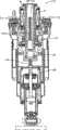
图1是根据可要求权利的本发明的第一实施例的用于车辆的电磁减震器的剖视图。FIG. 1 is a sectional view of an electromagnetic shock absorber for a vehicle according to a first embodiment of the claimable invention.
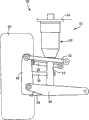
图2是示出其中布置有图1的电磁减震器的悬架设备的视图。FIG. 2 is a view showing a suspension apparatus in which the electromagnetic damper of FIG. 1 is disposed.
图3是示出图1的电磁减震器的杆转动禁止构件的结构的视图。FIG. 3 is a view showing the structure of a rod rotation inhibiting member of the electromagnetic damper of FIG. 1 .
图4是示出图1的电磁减震器的螺杆、以及其中在其外周部分整体上均形成有螺纹槽和花键槽的螺杆的视图。FIG. 4 is a view showing the screw of the electromagnetic damper of FIG. 1 , and the screw in which screw grooves and spline grooves are formed entirely on the outer peripheral portion thereof.
图5是示出图1的电磁减震器的螺杆、以及其中在其外周部分整体上均形成有螺纹槽和花键槽的螺杆的放大剖视图。5 is an enlarged cross-sectional view showing the screw of the electromagnetic damper of FIG. 1 , and the screw in which thread grooves and spline grooves are formed on the entirety of its outer peripheral portion.
图6是根据可要求权利的本发明的第二实施例的电磁减震器的剖视图。Fig. 6 is a cross-sectional view of an electromagnetic damper according to a second embodiment of the claimable invention.
图7是示出图6的电磁减震器的螺杆的视图。FIG. 7 is a view showing a screw of the electromagnetic damper of FIG. 6 .
图8是示出图6的电磁减震器的螺杆的放大剖视图。FIG. 8 is an enlarged sectional view showing a screw of the electromagnetic damper of FIG. 6 .
具体实施方式Detailed ways
将参考附图来详细描述根据可要求权利的本发明的一些实施例。但是,应该理解,可要求权利的本发明并不限于下述实施例的细节,而是可以在本领域技术人员可构思的各种修改及改变(例如以上“可要求权利的发明的构成方式”部分中所述的那些)的情况下进行实施。Some embodiments according to the claimable invention will be described in detail with reference to the accompanying drawings. However, it should be understood that the present invention that can be claimed is not limited to the details of the following embodiments, but various modifications and changes that can be conceived by those skilled in the art (such as the above "Constitution of the Claimable Invention" implementation in the case of those described in section).
1.第一实施例1. The first embodiment
1-1.电磁减震器的结构1-1. Structure of electromagnetic shock absorber
图1示出了根据可要求权利的本发明的第一实施例的用于车辆的减震器10(以下在合适的情况下简称为“减震器”)。例如,如图2所示,减震器10安装在车辆上,作为独立悬架设备20的一个构成元件。图2的悬架设备20是多连杆型的,并包括每个均作为悬架臂的第一上臂30、第二上臂32、第一下臂34、第二下臂36以及束角控制臂38。这五个臂30、32、34、36、38中的每一个的一端均以可转动的方式连接至车体,而另一端以可转动的方式连接至车轴承载器42,车轴承载器42以可转动的方式保持车轮40。得益于五个臂30、32、34、36、38,允许车轴承载器42沿着大致恒定的轨迹相对于车体竖直地运动。FIG. 1 shows a
在如此构造的悬架设备20中,减震器10与空气弹簧50并联布置。更具体而言,将减震器10与空气弹簧50一体化或集成得到的弹簧减震器组件52布置在安装部分54与作为簧下部分的一个构成部件的第二下臂36之间,安装部分54被设置在轮胎容纳部上并作为簧上部分的一个构成部件。In the thus configured
如图1所示,减震器10包括大致圆筒形壳体管60以及布置在壳体管60上方的电磁电动机62。壳体管60在其上端处固定地连接至容纳电磁电动机62的电动机壳体64。电动机壳体64在其外周部分处经由衬垫橡胶连接至安装部分54。As shown in FIG. 1 , the
电磁电动机62包括:沿着电动机壳体64的内壁表面固定地布置在一个圆周上的多个线圈70;以可转动的方式由电动机壳体64及壳体管60保持的中空圆筒形电动机轴72;以及固定地布置在电动机轴72的外周上以面向线圈70的多个永磁体74。电磁电动机62是三相无电刷式电动机,其包括具有线圈70的定子以及具有永磁体74的转子。The
减震器10在壳体管60中包括螺杆78以及螺母80,螺杆78其外周部分中形成有螺纹槽76,螺母80保持多个轴承滚珠(bearing balls)并与螺杆78进行螺纹配合。螺杆78与螺母80相互协同以构成滚珠丝杠机构。螺杆78布置在壳体管60内以沿着竖直方向延伸,同时穿过电磁电动机62的电动机轴72。螺母80固定地装配至电动机轴72的下端,并且与螺杆78进行螺纹配合。The
减震器10包括滚珠花键螺母(以下在合适的情况下简称为“花键螺母”)82,作为用于禁止螺杆78绕其轴线转动的杆转动禁止构件。花键螺母82固定至壳体管60的下端部,并且螺杆78穿过花键螺母82。如图3所示,花键螺母82形成有多个滚珠循环路径86,在每个路径86中均保持有多个轴承滚珠88以在路径86中循环。螺杆78形成有花键槽90,每个花键槽90均作为沿螺杆78的轴线方向延伸以分别面向滚珠循环路径86的轴向槽。作为配合部分的轴承滚珠88被构造为配合在花键槽90内。在本减震器10中,如此构造的滚珠花键机构在允许螺杆78沿轴线方向移动的同时禁止螺杆78绕其轴线转动。The
螺杆78在其下端处固定至杆支撑构件100的上表面,杆支撑构件100具有大致圆筒形状并在其一端处封闭。杆支撑构件100由覆盖阻尼器106(将在以下说明)的大致圆筒形阻尼器罩108通过两个压缩盘簧102、104进行弹性支撑,以容纳在阻尼器罩108内。更具体而言,杆支撑构件100在其下端处具有凸缘部分110。弹簧102在压缩状态下被保持在凸缘部分110与阻尼器罩108的上端部之间,并且弹簧104在压缩状态下被保持在凸缘部分110与阻尼器罩108的下端部之间。由于弹簧102、104的弹性力,杆支撑构件100由阻尼器罩108进行弹性支撑。阻尼器罩108在其下端部处固定至阻尼器106,具体而言,固定至作为阻尼器106的一个构成元件的阻尼器壳体112(将在以下说明)的外周部分。阻尼器106在其下端处经由安装衬套114连接至第二下臂36。换言之,杆支撑构件100通过压缩盘簧102、104弹性地连接至簧下部分,并且减震器10配备有由压缩盘簧102、104等构成的弹性连接构件。圆筒形罩管115固定至壳体管60的下部的外周表面,并且阻尼器罩108从罩管115的下端部插入罩管115。The
阻尼器106包括容纳工作流体的阻尼器壳体112、流体密封并且可滑动地配合在阻尼器壳体112的内部的活塞116、以及在其下端处连接至活塞116并且在其上端处向上延伸超过阻尼器壳体112顶部的活塞杆118。阻尼器主体112的内部被划分为位于活塞116下侧的下室120以及位于活塞116上侧的上室122。活塞杆118穿过布置在阻尼器壳体112的上部上的帽部124,并经由密封件与帽部124保持滑动接触。活塞杆118在其上端处固定至杆支撑构件100的封闭端的下表面。换言之,活塞杆118的上端固定地连接至螺杆78的下端,以相对于螺杆78不可移动且不可转动。The
阻尼器106具有与双管式(twin-tube type)减震器类似的结构。阻尼器壳体112包括外管126以及内管128,在两者之间形成有蓄液室130。活塞116流体密封并且可滑动地配合在内管128内。阻尼器106被构造为工作流体通过形成在活塞116内以沿着竖直方向穿透活塞116的连通通路而随着活塞116的移动在两个流体室120、122之间流动。阻尼器106还被构造为通过形成在连通通路内的孔口对工作流体在两个流体室120、122之间的流动施加阻抗。此外,布置在下室120与蓄液室130之间的基体阀构件132被构造为对工作流体在下室120与蓄液室130之间的流动施加阻抗。如此构造的阻尼器106配备有由形成在活塞116内的连通通路、基体阀构件等构成的流动阻抗施加机构。The
空气弹簧50由固定至安装部分54的室壳部140、连接至第二下臂36的空气活塞筒142、以及将室壳部140和空气活塞筒142连接的隔膜144构成。室壳部140是具有盖部的大致圆筒形构件。室壳部140在其盖部的上表面处经由衬垫橡胶固定至安装部分54的下侧,使得减震器10的电动机壳体64穿过形成在该盖部中的孔。在罩管115容纳在空气活塞筒142中的情况下,空气活塞筒142在其下端处固定至阻尼器罩108的外周部分。隔膜144的一端固定至室壳部140的下端,而另一端固定至空气活塞筒142的上端,由此室壳部140与空气活塞筒142经由隔膜144彼此连接以保持其两者之间的气密性。换言之,室壳部140、空气活塞筒142以及隔膜144相互协同以界定了压力室146。被构造为将压缩空气供应至压力室146和从压力室146排出压缩空气的空气供应排出装置被连接至压力室146。因为空气供应排出装置的结构为本领域所公知,将不再对其进行详细描述。The
环形衬垫橡胶150安装至壳体管60的下端。环形衬垫橡胶152安装至罩管115的下端的内壁表面。环形衬垫橡胶154安装至杆支撑构件100的封闭端的上表面。环形衬垫橡胶156安装至杆支撑构件100的封闭端的下表面。A ring-shaped
1.2电磁减震器的功能和控制1.2 Function and control of electromagnetic shock absorber
在减震器10中,连接至安装部分54的簧上侧单元由壳体管60、电动机壳体64、罩管115等构成,而连接至第二下臂36的簧下侧单元由杆支撑构件100等构成。簧上侧单元与簧下侧单元被构造为可相对于彼此进行移动。当簧上部分与簧下部分彼此于相对进行移动时,簧上侧单元与簧下侧单元相对于彼此进行移动,同时螺母80与螺杆78相对于彼此进行移动并且螺母80进行转动。电磁电动机62被构造为向螺母80施加转动力,而由于该转动力,减震器10能够产生对于簧上部分和簧下部分的相对移动的阻力。该阻力用作用于使簧上部分和簧下部分的相对振动衰减的阻尼力。换言之,减震器10被构造为基于由电磁电动机62产生的电动机力来产生对于簧上部分和簧下部分的相对振动的阻尼力。In the
将对具体的控制进行解释。电磁电动机62经由作为驱动电路的逆变器连接至电池。逆变器连接至控制装置。控制装置控制逆变器,由此控制由减震器10产生的阻尼力。因此,使簧上部分和簧下部分的相对振动衰减。更具体而言,用于对簧上部分与簧下部分之间的距离进行检测的行程传感器被连接至控制装置。控制装置基于由行程传感器检测到的簧上部分与簧下部分之间的距离来计算两者的相对速度,并根据计算得到的相对速度来计算要产生的阻尼力。控制装置基于计算得到的阻尼力向逆变器发出命令,并且逆变器对其开关器件进行控制,由此控制流经电磁电动机62的电流。由此,减震器10产生所需要的阻尼力。Specific controls will be explained. The
减震器10基于电动机力而具有使簧上部分和簧下部分彼此接近和远离的功能并具有使簧上部分与簧下部分之间的距离保持为合适值的功能。换言之,减震器10具有作为致动器的功能。由于该功能,可以基于天钩阻尼器原理(skyhook damper theory)来执行控制,其中相对于簧上部分的振动施加根据簧上绝对速度的阻尼力,以有效地抑制车体在转向时的侧倾和车体在加速或减速时的俯仰,并调节车辆的高度。The
如上所述,电磁电动机62的运转受到控制,由此减震器10产生合适的阻尼力。但是,当簧上部分和簧下部分的相对振动的频率变得高达一定程度时,电磁电动机62的运转因诸如电磁电动机62的控制响应性之类的某些因素而不能对振动进行跟随。在此情况下,基于由减震器10产生的力可能不能够获得充分的阻尼效果。着眼于此,在本减震器10中,簧下侧单元由簧下部分进行弹性支撑,并且设置了用于产生对于簧下侧单元和簧下部分的相对移动产生阻尼力的阻尼器106,由此有效地吸收诸如簧下谐振频率范围内的振动之类的高频振动。As described above, the operation of the
因为簧上侧单元由簧下部分进行弹性支撑,所以螺杆78也由簧下部分进行弹性支撑。因此,本减震器10采用上述滚珠花键机构以用于禁止螺杆78绕其轴线转动。具体而言,当螺杆78与螺母80彼此相对转动及移动时,转动力作用在螺杆78上。在此情况下,花键螺母82的支撑滚珠88与花键槽90的侧壁抵靠接触,由此禁止螺杆78绕其轴线转动。Since the sprung side unit is elastically supported by the unsprung portion, the
空气弹簧50的压力室146被填充有压缩空气。因此,由于压缩空气的压力,空气弹簧50使第二下臂36和安装部分54相对于彼此进行弹性支撑,即,使簧上部分和簧下部分相对于彼此进行弹性支撑。The
在本悬架设备20中,用于将压缩空气供应至压力室146和从压力室146排出压缩空气的空气供应排出装置的操作受到控制,由此可以调节压力室146内的空气量。通过调节空气量,来改变簧上部分与簧下部分之间在竖直方向上的距离,由此能够改变车辆高度。更具体而言,增大压力室146中的空气量以升高车辆高度,而减小空气量以降低车辆高度。In the
当簧上部分和簧下部分彼此接近到一定程度时,布置在阻尼器罩108的上端处的环形构件158经由衬垫橡胶150与壳体管60的下表面进行接触,或者壳体管60的下表面经由衬垫橡胶154与杆支撑构件100的上表面进行接触。另一方面,当簧上部分和簧下部分彼此远离到一定程度时,环形构件158经由衬垫橡胶152与罩管115的形成在其下端处的凸缘部分进行接触,或者阻尼器主体112的帽部124的上表面经由衬垫橡胶156与杆支撑构件100的封闭端的下表面进行接触。换言之,本减震器10配备有用于禁止簧上部分和簧下部分彼此接近地移动到小于两者间的规定距离的第一移动禁止机构(即,弹跳(bound)限位器),以及用于禁止簧上部分和簧下部分彼此远离地移动到大于两者间的规定距离的第二移动禁止机构(即,回弹(rebound)限位器)。When the sprung portion and the unsprung portion approach each other to a certain extent, the
1.3螺杆的螺纹槽和花键槽1.3 Screw thread groove and spline groove
如上所述,本减震器10具有所谓弹跳限位器及回弹限位器,由此限制减震器10伸缩的范围。因此,当减震器10伸缩时,螺母80可沿着轴线方向在螺杆78的外周部分上移动的范围受到限制,即,螺母80与螺纹槽76进行螺纹配合的范围受到限制。以下在合适的情况下将该范围称为“螺合范围”。此外,当减震器10伸缩时,花键螺母82可沿着轴线方向在螺杆78的外周部分上移动的范围受到限制,即,其中花键螺母82的多个轴承滚珠88被配合在花键槽90内的范围受到限制。以下在合适的情况下将该范围称为“配合范围”。As described above, the
具体而言,当作为壳体管60的下表面经由衬垫橡胶154与杆支撑构件100的上表面接触的结果而禁止簧上部分和簧下部分彼此接近地移动到小于两者之间的规定距离时,即,当完全弹跳时,螺母80和花键螺母82达到最接近螺杆78的基端部的状态。另一方面,当作为环形构件158经由衬垫橡胶152与罩管115的形成在其下端处的凸缘部分接触、以及阻尼器壳体112的帽部124的上表面经由衬垫橡胶156与杆支撑构件100的封闭端的下表面接触的结果而禁止簧上部分和簧下部分彼此远离地移动到大于两者之间的规定距离时,即,当完全回弹时,螺母80和花键螺母82达到最接近螺杆78的远端部的状态。以此方式,对螺合范围和配合范围进行限制。Specifically, when the sprung portion and the unsprung portion are prohibited from moving closer to each other to less than the specified distance therebetween as a result of the lower surface of the
在本减震器10中,如图4A和图5A所示,螺纹槽76仅在螺合范围内螺旋地形成在螺杆78的外周部分上。花键槽90仅在配合范围内形成在螺杆78的外周部分上以沿着轴线方向延伸。图5A是螺杆78的沿着图4A中的A-A’所取的剖视图。如图4B和图5B所示,替代其中螺纹槽76和花键槽90形成在螺杆78的各个特定范围内的螺杆78,可以采用螺纹槽160和花键槽162行成在螺杆164的整个外周部分上的螺杆164。图5B是螺杆164的沿着图4B中的A-A’所取的剖视图。在图4和图5中,右侧对应于螺杆的远端部一侧,即,簧上部分一侧,而左侧对应于螺杆的基端部一侧,即,簧下部分一侧。In the
在完全弹跳和完全回弹时,会存在簧上侧单元和簧下侧单元的相对移动突然停止并且螺杆78与螺母80的相对转动突然停止的情况。在此情况下,因为螺母80的惯性等因素,相对较大的转动力会作用在螺杆78上。因为不规则路面等造成的推动冲击的情况下,该转动力趋于在完全弹跳时比在完全回弹时变得更大。即使在该转动力作用在螺杆78上时,因为轴承滚珠88与花键槽90的侧壁的抵靠接触,仍可禁止螺杆78绕其轴线转动。严格意义上,对于一个花键槽90,由轴承滚珠与侧壁中一者的抵靠接触来禁止螺杆78沿着一个方向的转动,由轴承滚珠与侧壁中另一者的抵靠接触来禁止螺杆78沿着相反方向的转动。At the time of full bouncing and full rebound, there may be cases where the relative movement of the sprung side unit and the unsprung side unit stops suddenly and the relative rotation of the
在采用其中螺纹槽和花键槽形成在其外周部分整体上的螺杆164的减震器中,螺纹槽160沿着轴线方向在花键槽162整体上与花键槽162相交,因此如图5B所示,存在其中不具有花键槽162的侧壁的部分。以下在合适的情况下将那些部分称为“无壁部分”。因此,在完全弹跳时(由图4和图5中的单点划线表示)由花键螺母166禁止螺杆164的转动的情况下(假定作用在螺杆164上的转动力相对较大),位于花键槽162的无壁部分处的轴承滚珠并未保持与花键槽162的侧壁的接触,仅位于花键槽162的除无壁部分以外的其他部分(有壁部分)处的轴承滚珠保持与花键槽162的侧壁的接触。另一方面,在本减震器10中,在完全弹跳时螺杆78的外周部分的与花键螺母82(由单点划线表示)配合的区域处,如图4A和图5B所示,形成有花键槽90但并未形成有螺纹槽76。换言之,螺纹槽76并未形成在配合范围的与螺杆78的基端部更靠近的一端。因此,在本减震器10中,当完全弹跳时由花键螺母82禁止螺杆78的转动时,在配合范围的其中花键槽90内不存在无壁部分的上述一端处,花键槽90内的全部轴承滚珠88都保持与花键螺母82的侧壁接触。此外,在螺杆78的外周部分的特定范围内,并未形成螺纹槽76,由此减少了形成螺纹槽76的工时及成本。In the shock absorber employing the
如图4A和图5A所示,在本减震器10中,花键槽90并未形成在螺杆78的外周部分中的在完全回弹时与螺母80(由虚线表示)配合的区域处。换言之,花键槽90并未形成在螺合范围的与螺杆78的远端部更靠近的一端。在本减震器10中,花键槽90并未形成在螺杆78的外周部分的特定范围内,由此减少了用于形成花键槽90的工时及成本。As shown in FIGS. 4A and 5A , in the
如图5A所示,使本减震器10的螺杆78的花键槽90中每个花键槽90的深度在配合范围的相对两端部处比在相对两端部之间的中间部分处更小。换言之,使在每个花键槽90与在该花键槽90中滚动的每个轴承滚珠88之间的间隙在配合范围的相对两端部处比在相对两端部之间的中间部分处更小。更具体而言,使由每个花键槽90与花键螺母82界定的轴承滚珠88的通路的内径略小于每个轴承滚珠88的外径,即,将轴承滚珠88与花键槽90之间的间隙设定为所谓“-”或负间隙。将位于配合范围的除了相对两端部以外的其他部分处的上述间隙设定为“+”或正间隙。因此,在配合范围的相对两端部处,即减震器10的行程末端附近时,产生了对于螺杆78和花键螺母82的相对移动的阻力,由此降低减震器10的行程速度。因此,能够减轻在完全弹跳和完全回弹时对减震器10的冲击。在图5中,夸张地示出各个螺纹槽76、160以及花键槽90、162的形状以便于理解本减震器10的技术特征。As shown in FIG. 5A, the depth of each of the
2.第二实施例2. The second embodiment
图6示出了根据本发明的第二实施例的电磁减震器(以下在合适的情况下称为“减震器”)170。在所解释的第一实施例中的减震器10被构造为使得花键螺母82在螺杆78的其中螺母80与螺杆78进行螺纹配合的部分的两侧中更靠近螺杆78的基端部的一侧配合在花键槽90内。相反,在第二实施例中的减震器170被构造为滚珠花键螺母(以下在合适的情况下简称为“花键螺母”)172在螺杆174的其中螺母176与螺杆174进行螺纹配合的部分的两侧中更靠近螺杆174的远端部的一侧配合在花键槽178内。除了上述构造之外,第二实施例的减震器170在结构方面与上述第一实施例中的减震器10大致相同。因此,将针对滚珠丝杠机构及滚珠花键机构来说明减震器170,并且通过使用与第一实施例中使用的相同的附图标记,将省去或简化对与第一实施例中相同的构成元件的说明。FIG. 6 shows an electromagnetic damper (hereinafter referred to as "shock absorber" where appropriate) 170 according to a second embodiment of the present invention. The
减震器170包括螺杆174以及螺母176,螺杆174的外周部分形成有螺纹槽180,螺母176保持轴承滚珠并与螺杆174进行螺纹配合。螺母176在与螺杆174进行螺纹配合的同时,固定地配合至电动机轴72的下端。螺杆174布置在杆支撑构件100上以从其直立地延伸,并穿过电动机轴72。减震器170配备有花键螺母172,花键螺母172具有与所解释的第一实施例中的花键螺母82类似的结构。作为杆转动禁止构件的花键螺母172在螺杆174的其中螺母176与螺杆174进行螺纹配合的部分的一侧配合在螺杆174上,所述一侧更靠近螺杆174的远端部。更具体而言,圆筒形构件182从中空电动机轴72上方插入电动机轴72,圆筒形构件182在其上端处固定至电动机壳体64的帽部的下表面,而螺杆174的远端部从圆筒形构件182的下方插入圆筒形构件182。保持作为配合部分的多个轴承滚珠的花键螺母172被固定地配合至圆筒形构件182的下端部,使得螺杆174穿过花键螺母172。螺杆174具有花键槽178,每个花键槽178均作为形成在螺杆174的外周部分上使得多个轴承滚珠可以配合在其中的轴向槽。在本减震器170中,通过如此构造的滚珠花键机构,在允许螺杆174沿着轴线方向移动的同时,禁止螺杆174绕其轴线转动。The
与所解释的第一实施例中的减震器10类似,本减震器170配备有回弹限位器和弹跳限位器。因此,如图7和图8所示,螺合范围和配合范围受到限制。螺纹槽180仅螺旋地形成在螺杆174的外周部分上的螺合范围内,而花键槽178仅形成在螺杆174的外周部分上的配合范围内以沿着轴线方向延伸。图8是螺杆174的沿着图7中的C-C’所取的剖视图。在图7和图8中,右侧对应于螺杆的远端部一侧,即,簧上部分一侧,而左侧对应于螺杆的基端部一侧,即,簧下部分一侧。Similar to the
在本减震器170中,在螺杆174的外周部分中的在完全回弹时与花键螺母172(由虚线表示)配合的区域处,形成有花键槽178而并未形成有螺纹槽180。换言之,螺纹槽180并未形成在配合范围的与螺杆174的远端部接近的一端。因此,在本减震器170中,当完全回弹时由花键螺母172禁止螺杆174的转动时,在配合范围的其中在花键槽178中不存在无壁部分的上述一端处,花键槽178内的全部轴承滚珠均保持与花键槽178的侧壁接触。In the
与第一实施例中的减震器10类似,螺纹槽180并未形成在配合范围的特定区域内,并且花键槽178并未形成在螺合范围的特定区域内。因此,在本减震器170中,能够减少形成螺纹槽180和花键槽178的工时及成本。Similar to the
如图8所示,使本减震器170的螺杆174的螺纹槽180的大小或尺寸在螺合范围的相对两端部处比在相对两端部之间的中间部分处更小。换言之,使螺纹槽180与在花键槽178中滚动的各个轴承滚珠186之间的间隙在螺合范围的相对两端部处比在相对两端部之间的中间部分处更小。更具体而言,使由螺纹槽180和螺母176界定的轴承滚珠186的通路的内径略小于各个支撑滚珠186的外径,即,将轴承滚珠186与螺纹槽180之间的间隙设定为所谓“-”或负间隙。将在螺合范围的除了相对两端部之外的其他部分处的上述间隙设定为“+”或正间隙。因此,在螺合范围的相对两端部处,即在减震器170的行程末端附近,产生对于螺杆174和螺母176的相对移动的阻力,由此降低减震器170的行程速度。因此,能够在完全弹跳及完全回弹时减轻对减震器170的冲击。在图8中,夸张地示出了螺纹槽180和花键槽178每个的形状以便于理解本减震器170的技术特征。As shown in FIG. 8 , the size or dimension of the
权利要求书(按照条约第19条的修改)Claims (as amended under Article 19 of the Treaty)
1.(修改)一种电磁减震器,其用于车辆,并包括:1. (Modified) An electromagnetic shock absorber for a vehicle, comprising:
簧上侧单元,其连接至簧上部分;a sprung side unit connected to the sprung portion;
簧下侧单元,其连接至簧下部分,并被允许随着所述簧上部分和所述簧下部分的相对移动而相对于所述簧上侧单元进行移动;an unsprung side unit connected to the unsprung portion and permitted to move relative to the sprung side unit as the sprung portion and the unsprung portion move relative to each other;
丝杠机构,其包括:(a)螺杆,所述螺杆在其一个端部处由所述簧上侧单元和所述簧下侧单元中的一者支撑,并且所述螺杆具有形成在所述螺杆的外周部分中的螺纹槽以及形成在所述外周部分中并沿着所述螺杆的轴线方向延伸的轴向槽;以及(b)螺母,所述螺母以不可移动但可转动的方式由所述簧上侧单元和所述簧下侧单元中的另一者保持,并且所述螺母与所述螺杆进行螺纹配合,所述丝杠机构被构造为使得所述螺母随着所述簧上侧单元和所述簧下侧单元的相对移动而进行转动;A screw mechanism comprising: (a) a screw supported at one end thereof by one of the sprung side unit and the unsprung side unit, and having a screw formed on the a thread groove in an outer peripheral portion of the screw, and an axial groove formed in the outer peripheral portion and extending in the axial direction of the screw; and (b) a nut which is held in an immovable but rotatable manner by the The other of the sprung side unit and the unsprung side unit is held, and the nut is threadedly engaged with the screw, and the lead screw mechanism is configured such that the nut follows the sprung side The relative movement of the unit and the unsprung side unit rotates;
杆转动禁止构件,其包括被构造为配合在所述轴向槽内的配合部分,并且其在所述螺杆的与所述螺母进行螺纹配合的部分的相对两侧中的一侧、所述配合部分配合在所述轴向槽内的位置处,以不可移动且不可转动的方式布置在所述簧上侧单元和所述簧下侧单元中的所述另一者上,其中,所述相对两侧中的所述一侧更靠近所述螺杆的所述一个端部和另一个端部中的一者,所述杆转动禁止构件被构造为在允许所述螺杆沿着所述轴线方向相对于所述簧上侧单元和所述簧下侧单元中的所述另一者进行移动的同时,禁止所述螺杆相对于所述簧上侧单元和所述簧下侧单元中的所述另一者进行转动;以及a rod rotation inhibiting member, which includes a fitting portion configured to fit in the axial groove, and which is on one of opposite sides of a portion of the screw rod that is threadedly fitted to the nut, the fitting portion A position partially fitted in the axial groove is disposed on the other of the sprung side unit and the unsprung side unit in a non-movable and non-rotatable manner, wherein the opposite The one of the two sides is closer to one of the one end portion and the other end portion of the screw rod, and the rod rotation inhibiting member is configured to face each other while allowing the screw rod along the axis direction. While the other of the sprung-side unit and the unsprung-side unit moves, the screw rod is prohibited relative to the other of the sprung-side unit and the unsprung-side unit. one to rotate; and
电磁电动机,其向所述螺母施加转动力,an electromagnetic motor that applies a rotational force to said nut,
其中,所述电磁减震器被构造为基于所述转动力来产生对于所述簧上侧单元和所述簧下侧单元的相对移动的阻力,wherein the electromagnetic damper is configured to generate resistance to relative movement of the sprung side unit and the unsprung side unit based on the rotational force,
其中,将下述范围定义为配合范围:所述范围在所述螺杆的外周部分上沿着所述轴线方向延伸,并且在所述范围内存在所述轴向槽的情况下,在所述范围内允许所述配合部分随着所述簧上侧单元和所述簧下侧单元的相对移动而配合在所述轴向槽内,Wherein, the following range is defined as the fitting range: the range extends along the axial direction on the outer peripheral portion of the screw, and in the case where the axial groove exists in the range, allowing the fitting portion to fit in the axial groove along with the relative movement of the sprung side unit and the unsprung side unit,
其中,在所述配合范围中的、当所述配合部分位于所述配合范围的与所述螺杆的所述一个端部和所述另一个端部中的所述一者更靠近的一端时所述配合部分配合在所述轴向槽内所在的区域中,不形成所述螺纹槽,Wherein, in the fitting range, when the fitting portion is located at an end of the fitting range that is closer to the one of the one end portion and the other end portion of the screw rod, the said mating portion fits in said axial groove in an area where said thread groove is not formed,
其中,将下述范围定义为螺合范围:所述范围在所述螺杆的外周部分上沿着所述轴线方向延伸,并且在所述范围内存在所述螺纹槽的情况下,在所述范围内允许所述螺母随着所述簧上侧单元和所述簧下侧单元的相对移动而与所述螺纹槽进行螺纹配合,并且Wherein, the following range is defined as the screwing range: the range extends along the axis direction on the outer peripheral portion of the screw, and in the case where the thread groove exists within the range, within the range allowing the nut to be threadedly engaged with the thread groove as the sprung-side unit and the unsprung-side unit move relative to each other, and
其中,所述螺纹槽仅形成在所述螺合范围内。Wherein, the thread groove is only formed within the screw engagement range.
2.(删除)2. (deleted)
3.(修改)根据权利要求1所述的电磁减震器,3. (Modification) The electromagnetic shock absorber according to
其中,将下述范围定义为螺合范围:所述范围在所述螺杆的外周部分上沿着所述轴线方向延伸,并且在所述范围内存在所述螺纹槽的情况下,在所述范围内允许所述螺母随着所述簧上侧单元和所述簧下侧单元的相对移动而与所述螺纹槽进行螺纹配合,并且Wherein, the following range is defined as the screwing range: the range extends along the axis direction on the outer peripheral portion of the screw, and in the case where the thread groove exists within the range, within the range allowing the nut to be threadedly engaged with the thread groove as the sprung-side unit and the unsprung-side unit move relative to each other, and
其中,在所述螺合范围中的、当所述螺母位于所述螺合范围的与所述螺杆的所述一个端部和所述另一个端部中的另一者更靠近的一端时所述螺母与所述螺纹槽进行螺纹配合所在的区域中,不形成所述轴向槽。Wherein, in the threaded range, when the nut is located at an end of the screwed range that is closer to the other of the one end portion and the other end portion of the screw rod, the The axial groove is not formed in the region where the nut and the thread groove are screwed together.
4.根据权利要求1至3中任一项所述的电磁减震器,其中,所述轴向槽仅形成在所述配合范围内。4. The electromagnetic shock absorber according to any one of
5.根据权利要求1至4中任一项所述的电磁减震器,5. The electromagnetic shock absorber according to any one of
其中,将下述范围定义为配合范围:所述范围在所述螺杆的外周部分上沿着所述轴线方向延伸,并且在所述范围内存在所述轴向槽的情况下,在所述范围内允许所述配合部分随着所述簧上侧单元和所述簧下侧单元的相对移动而配合在所述轴向槽内,并且Wherein, the following range is defined as the fitting range: the range extends along the axial direction on the outer peripheral portion of the screw, and in the case where the axial groove exists in the range, allowing the fitting portion to fit in the axial groove as the sprung-side unit and the unsprung-side unit move relative to each other, and
其中,使所述轴向槽与所述配合部分之间的间隙在所述配合范围的相对两端部处比在所述相对两端部之间的中间部分处更小。Wherein, the gap between the axial groove and the fitting portion is made smaller at opposite end portions of the fitting range than at an intermediate portion between the opposite end portions.
6.根据权利要求1至5中任一项所述的电磁减震器,6. The electromagnetic shock absorber according to any one of
其中,将下述范围定义为螺合范围:所述范围在所述螺杆的外周部分上沿着所述轴线方向延伸,并且在所述范围内存在所述螺纹槽的情况下,在所述范围内允许所述螺母随着所述簧上侧单元和所述簧下侧单元的相对移动而与所述螺纹槽进行螺纹配合,并且Wherein, the following range is defined as the screwing range: the range extends along the axis direction on the outer peripheral portion of the screw, and in the case where the thread groove exists within the range, within the range allowing the nut to be threadedly engaged with the thread groove as the sprung-side unit and the unsprung-side unit move relative to each other, and
其中,使所述螺纹槽与所述螺母之间的间隙在所述螺合范围的相对两端部处比在所述相对两端部之间的中间部分处更小。Wherein, the gap between the thread groove and the nut is made smaller at opposite ends of the screwing range than at a middle portion between the opposite ends.
7.根据权利要求1至6中任一项所述的电磁减震器,其中,所述螺母保持在所述螺纹槽内滚动的多个轴承滚珠,并且所述丝杠机构是滚珠丝杠机构。7. The electromagnetic shock absorber according to any one of
8.根据权利要求1至7中任一项所述的电磁减震器,还包括:8. The electromagnetic shock absorber according to any one of
弹性连接构件,其用于将(a)所述簧上侧单元和所述簧下侧单元中的所述一者与(b)所述簧上部分和所述簧下部分中与所述簧上侧单元和所述簧下侧单元中的所述一者连接的一者进行弹性互连;以及an elastic connection member for connecting (a) the one of the sprung side unit and the unsprung side unit with (b) the sprung portion and the unsprung portion with the sprung the upper side unit and said one of said unsprung side units are elastically interconnected; and
阻尼器,其包括:壳体,其由所述簧上部分和所述簧下部分中的所述一者支撑,并在所述壳体的内部中容纳工作流体;活塞,其将所述壳体的内部划分为两个流体室,并可在所述壳体内移动;活塞杆,其具有连接至所述活塞的一端和从所述壳体延伸以与所述螺杆的所述一个端部一体地连接的另一端;以及流动阻抗施加机构,其对所述工作流体随着所述活塞的移动而在所述两个流体室之间的流动施加阻抗,所述阻尼器与所述弹性连接构件并联地布置,由此产生对于所述簧上侧单元和所述簧下侧单元中的所述一者与所述簧上部分和所述簧下部分中的所述一者的相对移动的阻尼力。A damper including: a housing supported by the one of the sprung portion and the unsprung portion and containing a working fluid in the interior of the housing; a piston connecting the housing The interior of the body is divided into two fluid chambers and is movable within the housing; a piston rod having one end connected to the piston and extending from the housing to be integral with the one end of the screw the other end connected to ground; and a flow resistance applying mechanism that applies resistance to the flow of the working fluid between the two fluid chambers as the piston moves, the damper and the elastic connection member arranged in parallel, thereby producing damping for the relative movement of the one of the sprung side unit and the unsprung side unit and the one of the sprung portion and the unsprung portion force.
9.根据权利要求1至8中任一项所述的电磁减震器,其中,所述电磁电动机包括中空圆筒形的电动机轴,并且所述电磁电动机在所述螺杆穿过所述电动机轴的状况下被布置在所述簧上侧单元和所述簧下侧单元中的所述另一者上,所述电动机轴用于在其一端处保持所述螺母。9. The electromagnetic shock absorber according to any one of
10.根据权利要求1至9中任一项所述的电磁减震器,10. The electromagnetic shock absorber according to any one of
其中,所述杆转动禁止构件是滚珠花键螺母,所述滚珠花键螺母保持在所述轴向槽内滚动的多个轴承滚珠,并且所述螺杆穿过所述滚珠花键螺母,并且wherein the rod rotation inhibiting member is a ball spline nut holding a plurality of bearing balls rolling in the axial groove, and the screw rod passes through the ball spline nut, and
其中,所述配合部分由所述多个轴承滚珠构成。Wherein, the matching part is formed by the plurality of bearing balls.
11.根据权利要求1至10中任一项所述的电磁减震器,11. The electromagnetic shock absorber according to any one of
其中,所述杆转动禁止构件被布置在所述螺杆的与所述螺母进行螺纹配合的部分的一侧、所述配合部分配合在所述轴向槽内的位置处,所述一侧更靠近所述螺杆的所述一个端部,并且Wherein, the rod rotation inhibiting member is arranged on one side of the part of the screw that is threadedly engaged with the nut, at a position where the fitting part fits in the axial groove, the side is closer to said one end of said screw, and
其中,所述簧上侧单元和所述簧下侧单元中的所述一者是所述簧下侧单元,而所述簧上侧单元和所述簧下侧单元中的所述另一者是所述簧上侧单元。Wherein, the one of the sprung-side unit and the unsprung-side unit is the unsprung-side unit, and the other of the sprung-side unit and the unsprung-side unit is is the sprung side unit.
12.根据权利要求1至11中任一项所述的电磁减震器,还包括下述机构中的至少一者:12. The electromagnetic shock absorber according to any one of
第一移动禁止机构,其用于禁止所述簧上部分和所述簧下部分彼此接近到小于规定距离的相对移动;以及a first movement inhibiting mechanism for inhibiting relative movement of the sprung portion and the unsprung portion approaching each other less than a prescribed distance; and
第二移动禁止机构,其用于禁止所述簧上部分和所述簧下部分彼此远离到大于规定距离的相对移动。A second movement inhibiting mechanism for inhibiting relative movement of the sprung portion and the unsprung portion away from each other by more than a prescribed distance.
Claims (12)
Translated fromChineseApplications Claiming Priority (3)
| Application Number | Priority Date | Filing Date | Title |
|---|---|---|---|
| JP2007-277200 | 2007-10-25 | ||
| JP2007277200AJP5260936B2 (en) | 2007-10-25 | 2007-10-25 | Electromagnetic shock absorber for vehicles |
| PCT/JP2008/068918WO2009054331A1 (en) | 2007-10-25 | 2008-10-10 | Electromagnetic shock absorber for vehicle |
Publications (2)
| Publication Number | Publication Date |
|---|---|
| CN101801695Atrue CN101801695A (en) | 2010-08-11 |
| CN101801695B CN101801695B (en) | 2012-11-28 |
Family
ID=40042728
Family Applications (1)
| Application Number | Title | Priority Date | Filing Date |
|---|---|---|---|
| CN200880107945.6AExpired - Fee RelatedCN101801695B (en) | 2007-10-25 | 2008-10-10 | Electromagnetic shock absorbers for vehicles |
Country Status (5)
| Country | Link |
|---|---|
| US (1) | US8668060B2 (en) |
| EP (1) | EP2200848B1 (en) |
| JP (1) | JP5260936B2 (en) |
| CN (1) | CN101801695B (en) |
| WO (1) | WO2009054331A1 (en) |
Cited By (8)
| Publication number | Priority date | Publication date | Assignee | Title |
|---|---|---|---|---|
| CN105546010A (en)* | 2016-01-22 | 2016-05-04 | 山东理工大学 | Three-phase electro-magnetic doubly-salient telescopic shock absorber |
| CN105822713A (en)* | 2015-01-23 | 2016-08-03 | 丰田自动车株式会社 | Vehicular damping force generation device |
| US9827822B2 (en) | 2015-01-23 | 2017-11-28 | Toyota Jidosha Kabushiki Kaisha | Damping force generation device for vehicle |
| US9909633B2 (en) | 2015-02-10 | 2018-03-06 | Toyota Jidosha Kabushiki Kaisha | Braking force generation device of vehicle |
| CN112238192A (en)* | 2019-07-17 | 2021-01-19 | 会田工程技术有限公司 | Workpiece conveying system of multi-station press |
| CN116160814A (en)* | 2023-02-27 | 2023-05-26 | 重庆赛力斯新能源汽车设计院有限公司 | A damping adjustment method, device and medium of an electromagnetic shock absorber with reference to road conditions |
| US20230241969A1 (en)* | 2021-04-27 | 2023-08-03 | Luis Marcial Medina | Suspension power electric generator |
| CN116624544A (en)* | 2023-05-10 | 2023-08-22 | 浙江极氪智能科技有限公司 | Shock absorber and vehicle |
Families Citing this family (43)
| Publication number | Priority date | Publication date | Assignee | Title |
|---|---|---|---|---|
| US7678128B2 (en) | 2001-06-29 | 2010-03-16 | Advanced Cardiovascular Systems, Inc. | Delivery and recovery sheaths for medical devices |
| JP4464798B2 (en)* | 2004-11-24 | 2010-05-19 | トヨタ自動車株式会社 | Vehicle suspension system |
| JP5027473B2 (en)* | 2006-10-11 | 2012-09-19 | カヤバ工業株式会社 | Suspension device |
| US8490761B2 (en)* | 2008-02-08 | 2013-07-23 | Takuhiro Kondo | Suspension device |
| JP4737222B2 (en)* | 2008-04-18 | 2011-07-27 | トヨタ自動車株式会社 | Vehicle suspension system |
| JP5142810B2 (en)* | 2008-05-09 | 2013-02-13 | カヤバ工業株式会社 | Suspension device |
| JP5424751B2 (en)* | 2009-07-10 | 2014-02-26 | カヤバ工業株式会社 | Suspension device |
| JP5261316B2 (en)* | 2009-08-05 | 2013-08-14 | カヤバ工業株式会社 | Suspension device |
| JP5267418B2 (en)* | 2009-10-19 | 2013-08-21 | トヨタ自動車株式会社 | Shock absorber equipment |
| US8448952B2 (en)* | 2011-05-31 | 2013-05-28 | GM Global Technology Operations LLC | Vehicle with active-regenerative suspension |
| US8641053B2 (en) | 2012-02-27 | 2014-02-04 | Bose Corporation | Actuator assembly |
| JP5925672B2 (en)* | 2012-12-27 | 2016-05-25 | 株式会社構造計画研究所 | Damping device and structure damping device |
| US9404548B2 (en)* | 2013-12-13 | 2016-08-02 | Chi Hua Fitness Co., Ltd. | Adaptable damper |
| JP6079700B2 (en) | 2014-05-27 | 2017-02-15 | トヨタ自動車株式会社 | Absorber system for vehicles |
| JP6191547B2 (en)* | 2014-06-05 | 2017-09-06 | トヨタ自動車株式会社 | Shock absorber system |
| US10300760B1 (en) | 2015-03-18 | 2019-05-28 | Apple Inc. | Fully-actuated suspension system |
| US9713945B1 (en)* | 2015-12-11 | 2017-07-25 | Arnott T&P Holding, Llc | Motor vehicle shock with assist coil device, apparatus, system and method |
| US9707817B1 (en)* | 2015-12-11 | 2017-07-18 | Arnott T&P Holding, Llc | Shock apparatus, method and system for all vehicles |
| US9708028B1 (en)* | 2015-12-11 | 2017-07-18 | Arnott T&P Holding, Llc | Motorcycle shock with assist coil device, apparatus, system and method |
| US9714066B1 (en) | 2015-12-11 | 2017-07-25 | Arnott T&P Holding, Llc | Decoupled damper and airspring suspension system, device, apparatus and method for motorcycles |
| WO2018126245A2 (en)* | 2016-12-30 | 2018-07-05 | Axel Michael Sigmar | Adaptive polyphase motor |
| US10814690B1 (en) | 2017-04-18 | 2020-10-27 | Apple Inc. | Active suspension system with energy storage device |
| JP2020518514A (en) | 2017-05-08 | 2020-06-25 | アップル インコーポレイテッドApple Inc. | Active suspension system |
| US10899340B1 (en) | 2017-06-21 | 2021-01-26 | Apple Inc. | Vehicle with automated subsystems |
| US11173766B1 (en) | 2017-09-07 | 2021-11-16 | Apple Inc. | Suspension system with locking structure |
| US10906370B1 (en)* | 2017-09-15 | 2021-02-02 | Apple Inc. | Active suspension system |
| US11124035B1 (en) | 2017-09-25 | 2021-09-21 | Apple Inc. | Multi-stage active suspension actuator |
| US10960723B1 (en) | 2017-09-26 | 2021-03-30 | Apple Inc. | Wheel-mounted suspension actuators |
| US10690215B2 (en)* | 2018-02-23 | 2020-06-23 | Tenneco Automotive Operating Company Inc. | Damper with electro-magnetic actuator |
| US11285773B1 (en) | 2018-09-12 | 2022-03-29 | Apple Inc. | Control system |
| US11634167B1 (en) | 2018-09-14 | 2023-04-25 | Apple Inc. | Transmitting axial and rotational movement to a hub |
| US11345209B1 (en) | 2019-06-03 | 2022-05-31 | Apple Inc. | Suspension systems |
| US11179991B1 (en) | 2019-09-23 | 2021-11-23 | Apple Inc. | Suspension systems |
| US11938922B1 (en) | 2019-09-23 | 2024-03-26 | Apple Inc. | Motion control system |
| JP6738510B1 (en)* | 2020-03-23 | 2020-08-12 | 株式会社ショーワ | Fluid supply device, height adjustment device, saddle type vehicle |
| US11707961B1 (en) | 2020-04-28 | 2023-07-25 | Apple Inc. | Actuator with reinforcing structure for torsion resistance |
| US11828339B1 (en) | 2020-07-07 | 2023-11-28 | Apple Inc. | Vibration control system |
| JP7524662B2 (en)* | 2020-08-04 | 2024-07-30 | セイコーエプソン株式会社 | robot |
| US12017498B2 (en) | 2021-06-07 | 2024-06-25 | Apple Inc. | Mass damper system |
| US11953080B1 (en) | 2021-09-24 | 2024-04-09 | Apple Inc. | Shaft with surface finished ridges |
| US12251973B2 (en) | 2022-06-10 | 2025-03-18 | Apple Inc. | Vibration absorber |
| US12168375B1 (en) | 2023-01-26 | 2024-12-17 | Apple Inc. | Motion control system |
| CN118912138B (en)* | 2024-10-12 | 2025-03-11 | 浙江戈尔德智能悬架股份有限公司 | A shock absorber electromagnetic damping valve device and assembly method |
Family Cites Families (12)
| Publication number | Priority date | Publication date | Assignee | Title |
|---|---|---|---|---|
| JPH079260B2 (en)* | 1988-03-05 | 1995-02-01 | 博 寺町 | Combined movement guide device |
| JPH0619873Y2 (en)* | 1989-09-05 | 1994-05-25 | 日本トムソン株式会社 | Ball screw spline unit |
| JP3294672B2 (en) | 1993-06-07 | 2002-06-24 | 株式会社ショーワ | Height adjustment device |
| JPH0737765A (en) | 1993-07-22 | 1995-02-07 | Elna Co Ltd | Electrolytic capacitor |
| JPH11141644A (en)* | 1997-11-13 | 1999-05-25 | Thk Co Ltd | Limited stroke ball screw device |
| EP1508707A4 (en)* | 2002-05-14 | 2006-10-04 | Thk Co Ltd | Shaft member with vibration damping function |
| CN2686889Y (en)* | 2004-02-19 | 2005-03-23 | 郭川 | Electrjical-controlled variable damp shock absorber |
| CN100387864C (en)* | 2004-04-22 | 2008-05-14 | 萱场工业株式会社 | Electromagnetic shock absorbers for vehicles |
| JP4464798B2 (en) | 2004-11-24 | 2010-05-19 | トヨタ自動車株式会社 | Vehicle suspension system |
| JP4396611B2 (en)* | 2005-10-07 | 2010-01-13 | トヨタ自動車株式会社 | Suspension cylinder device for vehicle |
| JP2007203933A (en)* | 2006-02-03 | 2007-08-16 | Toyota Motor Corp | Suspension device |
| JP4667338B2 (en)* | 2006-10-11 | 2011-04-13 | カヤバ工業株式会社 | Shock absorber |
- 2007
- 2007-10-25JPJP2007277200Apatent/JP5260936B2/ennot_activeExpired - Fee Related
- 2008
- 2008-10-10CNCN200880107945.6Apatent/CN101801695B/ennot_activeExpired - Fee Related
- 2008-10-10USUS12/679,768patent/US8668060B2/ennot_activeExpired - Fee Related
- 2008-10-10EPEP08842422Apatent/EP2200848B1/ennot_activeNot-in-force
- 2008-10-10WOPCT/JP2008/068918patent/WO2009054331A1/enactiveApplication Filing
Cited By (10)
| Publication number | Priority date | Publication date | Assignee | Title |
|---|---|---|---|---|
| CN105822713A (en)* | 2015-01-23 | 2016-08-03 | 丰田自动车株式会社 | Vehicular damping force generation device |
| US9827822B2 (en) | 2015-01-23 | 2017-11-28 | Toyota Jidosha Kabushiki Kaisha | Damping force generation device for vehicle |
| CN105822713B (en)* | 2015-01-23 | 2018-01-30 | 丰田自动车株式会社 | The decay force generating apparatus of vehicle |
| US9909633B2 (en) | 2015-02-10 | 2018-03-06 | Toyota Jidosha Kabushiki Kaisha | Braking force generation device of vehicle |
| CN105546010A (en)* | 2016-01-22 | 2016-05-04 | 山东理工大学 | Three-phase electro-magnetic doubly-salient telescopic shock absorber |
| CN112238192A (en)* | 2019-07-17 | 2021-01-19 | 会田工程技术有限公司 | Workpiece conveying system of multi-station press |
| US20230241969A1 (en)* | 2021-04-27 | 2023-08-03 | Luis Marcial Medina | Suspension power electric generator |
| US11890931B2 (en)* | 2021-04-27 | 2024-02-06 | Luis Marcial Medina | Suspension power electric generator |
| CN116160814A (en)* | 2023-02-27 | 2023-05-26 | 重庆赛力斯新能源汽车设计院有限公司 | A damping adjustment method, device and medium of an electromagnetic shock absorber with reference to road conditions |
| CN116624544A (en)* | 2023-05-10 | 2023-08-22 | 浙江极氪智能科技有限公司 | Shock absorber and vehicle |
Also Published As
| Publication number | Publication date |
|---|---|
| CN101801695B (en) | 2012-11-28 |
| EP2200848B1 (en) | 2012-11-21 |
| US8668060B2 (en) | 2014-03-11 |
| US20100200343A1 (en) | 2010-08-12 |
| EP2200848A1 (en) | 2010-06-30 |
| JP5260936B2 (en) | 2013-08-14 |
| JP2009101942A (en) | 2009-05-14 |
| WO2009054331A1 (en) | 2009-04-30 |
Similar Documents
| Publication | Publication Date | Title |
|---|---|---|
| CN101801695B (en) | Electromagnetic shock absorbers for vehicles | |
| JP3660208B2 (en) | damper | |
| US9586456B2 (en) | Recuperating passive and active suspension | |
| KR100865644B1 (en) | Suspension device for vehicle | |
| US8127900B2 (en) | Electromagnetic shock absorber for vehicle | |
| US10589591B2 (en) | Active damper system actuator arrangement | |
| CN105008756A (en) | Spring bumper nose retainer for shock absorbers | |
| KR20190104814A (en) | Apparatus of adjusting vehicle height for macpherson strut suspension | |
| JP2008143436A (en) | Electromagnetic shock absorber for vehicles | |
| CN113803399A (en) | High-load magnetorheological fluid-elastic three-way vibration damper | |
| CN201916409U (en) | Motor vehicle shock absorber | |
| CN204372028U (en) | Amplitude is correlated with damping characteristic vibration damper | |
| JP2008100539A (en) | Vehicle suspension system | |
| KR102185230B1 (en) | Air Spring with Function to Adjust the Height for MR Damper | |
| JP4708392B2 (en) | Electromagnetic shock absorber | |
| JP2008285062A (en) | Vehicle suspension system | |
| JP2008215588A (en) | Electromagnetic shock absorber | |
| JP2010025139A (en) | Suspension device for vehicle | |
| JP2008256179A (en) | Electromagnetic absorber for vehicles | |
| JP5086011B2 (en) | Magnetorheological fluid shock absorber | |
| JP2008202738A (en) | Vehicle suspension system | |
| KR101272753B1 (en) | Damping force variable apparatus | |
| JP2008247054A (en) | Vehicle suspension system | |
| JP3114015U (en) | Hybrid suspension | |
| JP2022185803A (en) | air suspension device |
Legal Events
| Date | Code | Title | Description |
|---|---|---|---|
| C06 | Publication | ||
| PB01 | Publication | ||
| C10 | Entry into substantive examination | ||
| SE01 | Entry into force of request for substantive examination | ||
| C14 | Grant of patent or utility model | ||
| GR01 | Patent grant | ||
| C56 | Change in the name or address of the patentee | ||
| CP01 | Change in the name or title of a patent holder | Address after:Aichi Prefecture, Japan Patentee after:Toyota Motor Corp. Patentee after:KYB Corp. Patentee after:JTEKT Corp. Address before:Aichi Prefecture, Japan Patentee before:Toyota Motor Corp. Patentee before:KAYABA INDUSTRY Co.,Ltd. Patentee before:JTEKT Corp. | |
| CF01 | Termination of patent right due to non-payment of annual fee | ||
| CF01 | Termination of patent right due to non-payment of annual fee | Granted publication date:20121128 Termination date:20171010 |