CN101801432A - Cartridge system integrated device - Google Patents
Cartridge system integrated deviceDownload PDFInfo
- Publication number
- CN101801432A CN101801432ACN200880013768ACN200880013768ACN101801432ACN 101801432 ACN101801432 ACN 101801432ACN 200880013768 ACN200880013768 ACN 200880013768ACN 200880013768 ACN200880013768 ACN 200880013768ACN 101801432 ACN101801432 ACN 101801432A
- Authority
- CN
- China
- Prior art keywords
- fluid
- pump
- box
- valve
- chamber
- Prior art date
- Legal status (The legal status is an assumption and is not a legal conclusion. Google has not performed a legal analysis and makes no representation as to the accuracy of the status listed.)
- Granted
Links
Images


Classifications
- F—MECHANICAL ENGINEERING; LIGHTING; HEATING; WEAPONS; BLASTING
- F04—POSITIVE - DISPLACEMENT MACHINES FOR LIQUIDS; PUMPS FOR LIQUIDS OR ELASTIC FLUIDS
- F04B—POSITIVE-DISPLACEMENT MACHINES FOR LIQUIDS; PUMPS
- F04B43/00—Machines, pumps, or pumping installations having flexible working members
- F04B43/02—Machines, pumps, or pumping installations having flexible working members having plate-like flexible members, e.g. diaphragms
- F04B43/025—Machines, pumps, or pumping installations having flexible working members having plate-like flexible members, e.g. diaphragms two or more plate-like pumping members in parallel
- F04B43/026—Machines, pumps, or pumping installations having flexible working members having plate-like flexible members, e.g. diaphragms two or more plate-like pumping members in parallel each plate-like pumping flexible member working in its own pumping chamber
- A—HUMAN NECESSITIES
- A61—MEDICAL OR VETERINARY SCIENCE; HYGIENE
- A61M—DEVICES FOR INTRODUCING MEDIA INTO, OR ONTO, THE BODY; DEVICES FOR TRANSDUCING BODY MEDIA OR FOR TAKING MEDIA FROM THE BODY; DEVICES FOR PRODUCING OR ENDING SLEEP OR STUPOR
- A61M1/00—Suction or pumping devices for medical purposes; Devices for carrying-off, for treatment of, or for carrying-over, body-liquids; Drainage systems
- A61M1/14—Dialysis systems; Artificial kidneys; Blood oxygenators ; Reciprocating systems for treatment of body fluids, e.g. single needle systems for hemofiltration or pheresis
- A61M1/15—Dialysis systems; Artificial kidneys; Blood oxygenators ; Reciprocating systems for treatment of body fluids, e.g. single needle systems for hemofiltration or pheresis with a cassette forming partially or totally the flow circuit for the treating fluid, e.g. the dialysate fluid circuit or the treating gas circuit
- A61M1/154—Dialysis systems; Artificial kidneys; Blood oxygenators ; Reciprocating systems for treatment of body fluids, e.g. single needle systems for hemofiltration or pheresis with a cassette forming partially or totally the flow circuit for the treating fluid, e.g. the dialysate fluid circuit or the treating gas circuit with sensing means or components thereof
- A—HUMAN NECESSITIES
- A61—MEDICAL OR VETERINARY SCIENCE; HYGIENE
- A61M—DEVICES FOR INTRODUCING MEDIA INTO, OR ONTO, THE BODY; DEVICES FOR TRANSDUCING BODY MEDIA OR FOR TAKING MEDIA FROM THE BODY; DEVICES FOR PRODUCING OR ENDING SLEEP OR STUPOR
- A61M1/00—Suction or pumping devices for medical purposes; Devices for carrying-off, for treatment of, or for carrying-over, body-liquids; Drainage systems
- A61M1/14—Dialysis systems; Artificial kidneys; Blood oxygenators ; Reciprocating systems for treatment of body fluids, e.g. single needle systems for hemofiltration or pheresis
- A61M1/15—Dialysis systems; Artificial kidneys; Blood oxygenators ; Reciprocating systems for treatment of body fluids, e.g. single needle systems for hemofiltration or pheresis with a cassette forming partially or totally the flow circuit for the treating fluid, e.g. the dialysate fluid circuit or the treating gas circuit
- A61M1/155—Dialysis systems; Artificial kidneys; Blood oxygenators ; Reciprocating systems for treatment of body fluids, e.g. single needle systems for hemofiltration or pheresis with a cassette forming partially or totally the flow circuit for the treating fluid, e.g. the dialysate fluid circuit or the treating gas circuit with treatment-fluid pumping means or components thereof
- A—HUMAN NECESSITIES
- A61—MEDICAL OR VETERINARY SCIENCE; HYGIENE
- A61M—DEVICES FOR INTRODUCING MEDIA INTO, OR ONTO, THE BODY; DEVICES FOR TRANSDUCING BODY MEDIA OR FOR TAKING MEDIA FROM THE BODY; DEVICES FOR PRODUCING OR ENDING SLEEP OR STUPOR
- A61M1/00—Suction or pumping devices for medical purposes; Devices for carrying-off, for treatment of, or for carrying-over, body-liquids; Drainage systems
- A61M1/14—Dialysis systems; Artificial kidneys; Blood oxygenators ; Reciprocating systems for treatment of body fluids, e.g. single needle systems for hemofiltration or pheresis
- A61M1/15—Dialysis systems; Artificial kidneys; Blood oxygenators ; Reciprocating systems for treatment of body fluids, e.g. single needle systems for hemofiltration or pheresis with a cassette forming partially or totally the flow circuit for the treating fluid, e.g. the dialysate fluid circuit or the treating gas circuit
- A61M1/156—Constructional details of the cassette, e.g. specific details on material or shape
- A61M1/1561—Constructional details of the cassette, e.g. specific details on material or shape at least one cassette surface or portion thereof being flexible, e.g. the cassette having a rigid base portion with preformed channels and being covered with a foil
- A—HUMAN NECESSITIES
- A61—MEDICAL OR VETERINARY SCIENCE; HYGIENE
- A61M—DEVICES FOR INTRODUCING MEDIA INTO, OR ONTO, THE BODY; DEVICES FOR TRANSDUCING BODY MEDIA OR FOR TAKING MEDIA FROM THE BODY; DEVICES FOR PRODUCING OR ENDING SLEEP OR STUPOR
- A61M1/00—Suction or pumping devices for medical purposes; Devices for carrying-off, for treatment of, or for carrying-over, body-liquids; Drainage systems
- A61M1/14—Dialysis systems; Artificial kidneys; Blood oxygenators ; Reciprocating systems for treatment of body fluids, e.g. single needle systems for hemofiltration or pheresis
- A61M1/15—Dialysis systems; Artificial kidneys; Blood oxygenators ; Reciprocating systems for treatment of body fluids, e.g. single needle systems for hemofiltration or pheresis with a cassette forming partially or totally the flow circuit for the treating fluid, e.g. the dialysate fluid circuit or the treating gas circuit
- A61M1/156—Constructional details of the cassette, e.g. specific details on material or shape
- A61M1/1562—Details of incorporated reservoirs
- A61M1/15625—Details of incorporated reservoirs the reservoirs acting as balance chambers
- A—HUMAN NECESSITIES
- A61—MEDICAL OR VETERINARY SCIENCE; HYGIENE
- A61M—DEVICES FOR INTRODUCING MEDIA INTO, OR ONTO, THE BODY; DEVICES FOR TRANSDUCING BODY MEDIA OR FOR TAKING MEDIA FROM THE BODY; DEVICES FOR PRODUCING OR ENDING SLEEP OR STUPOR
- A61M1/00—Suction or pumping devices for medical purposes; Devices for carrying-off, for treatment of, or for carrying-over, body-liquids; Drainage systems
- A61M1/14—Dialysis systems; Artificial kidneys; Blood oxygenators ; Reciprocating systems for treatment of body fluids, e.g. single needle systems for hemofiltration or pheresis
- A61M1/15—Dialysis systems; Artificial kidneys; Blood oxygenators ; Reciprocating systems for treatment of body fluids, e.g. single needle systems for hemofiltration or pheresis with a cassette forming partially or totally the flow circuit for the treating fluid, e.g. the dialysate fluid circuit or the treating gas circuit
- A61M1/156—Constructional details of the cassette, e.g. specific details on material or shape
- A61M1/1565—Details of valves
- A—HUMAN NECESSITIES
- A61—MEDICAL OR VETERINARY SCIENCE; HYGIENE
- A61M—DEVICES FOR INTRODUCING MEDIA INTO, OR ONTO, THE BODY; DEVICES FOR TRANSDUCING BODY MEDIA OR FOR TAKING MEDIA FROM THE BODY; DEVICES FOR PRODUCING OR ENDING SLEEP OR STUPOR
- A61M1/00—Suction or pumping devices for medical purposes; Devices for carrying-off, for treatment of, or for carrying-over, body-liquids; Drainage systems
- A61M1/14—Dialysis systems; Artificial kidneys; Blood oxygenators ; Reciprocating systems for treatment of body fluids, e.g. single needle systems for hemofiltration or pheresis
- A61M1/16—Dialysis systems; Artificial kidneys; Blood oxygenators ; Reciprocating systems for treatment of body fluids, e.g. single needle systems for hemofiltration or pheresis with membranes
- A61M1/1601—Control or regulation
- A61M1/1603—Regulation parameters
- A61M1/1605—Physical characteristics of the dialysate fluid
- A—HUMAN NECESSITIES
- A61—MEDICAL OR VETERINARY SCIENCE; HYGIENE
- A61M—DEVICES FOR INTRODUCING MEDIA INTO, OR ONTO, THE BODY; DEVICES FOR TRANSDUCING BODY MEDIA OR FOR TAKING MEDIA FROM THE BODY; DEVICES FOR PRODUCING OR ENDING SLEEP OR STUPOR
- A61M1/00—Suction or pumping devices for medical purposes; Devices for carrying-off, for treatment of, or for carrying-over, body-liquids; Drainage systems
- A61M1/14—Dialysis systems; Artificial kidneys; Blood oxygenators ; Reciprocating systems for treatment of body fluids, e.g. single needle systems for hemofiltration or pheresis
- A61M1/16—Dialysis systems; Artificial kidneys; Blood oxygenators ; Reciprocating systems for treatment of body fluids, e.g. single needle systems for hemofiltration or pheresis with membranes
- A61M1/1621—Constructional aspects thereof
- A61M1/1635—Constructional aspects thereof with volume chamber balancing devices between used and fresh dialysis fluid
- A61M1/1639—Constructional aspects thereof with volume chamber balancing devices between used and fresh dialysis fluid linked by membranes
- A—HUMAN NECESSITIES
- A61—MEDICAL OR VETERINARY SCIENCE; HYGIENE
- A61M—DEVICES FOR INTRODUCING MEDIA INTO, OR ONTO, THE BODY; DEVICES FOR TRANSDUCING BODY MEDIA OR FOR TAKING MEDIA FROM THE BODY; DEVICES FOR PRODUCING OR ENDING SLEEP OR STUPOR
- A61M1/00—Suction or pumping devices for medical purposes; Devices for carrying-off, for treatment of, or for carrying-over, body-liquids; Drainage systems
- A61M1/14—Dialysis systems; Artificial kidneys; Blood oxygenators ; Reciprocating systems for treatment of body fluids, e.g. single needle systems for hemofiltration or pheresis
- A61M1/16—Dialysis systems; Artificial kidneys; Blood oxygenators ; Reciprocating systems for treatment of body fluids, e.g. single needle systems for hemofiltration or pheresis with membranes
- A61M1/1654—Dialysates therefor
- A61M1/1656—Apparatus for preparing dialysates
- A61M1/166—Heating
- A61M1/1664—Heating with temperature control
- A—HUMAN NECESSITIES
- A61—MEDICAL OR VETERINARY SCIENCE; HYGIENE
- A61M—DEVICES FOR INTRODUCING MEDIA INTO, OR ONTO, THE BODY; DEVICES FOR TRANSDUCING BODY MEDIA OR FOR TAKING MEDIA FROM THE BODY; DEVICES FOR PRODUCING OR ENDING SLEEP OR STUPOR
- A61M1/00—Suction or pumping devices for medical purposes; Devices for carrying-off, for treatment of, or for carrying-over, body-liquids; Drainage systems
- A61M1/14—Dialysis systems; Artificial kidneys; Blood oxygenators ; Reciprocating systems for treatment of body fluids, e.g. single needle systems for hemofiltration or pheresis
- A61M1/16—Dialysis systems; Artificial kidneys; Blood oxygenators ; Reciprocating systems for treatment of body fluids, e.g. single needle systems for hemofiltration or pheresis with membranes
- A61M1/1654—Dialysates therefor
- A61M1/1656—Apparatus for preparing dialysates
- A61M1/1666—Apparatus for preparing dialysates by dissolving solids
- A—HUMAN NECESSITIES
- A61—MEDICAL OR VETERINARY SCIENCE; HYGIENE
- A61M—DEVICES FOR INTRODUCING MEDIA INTO, OR ONTO, THE BODY; DEVICES FOR TRANSDUCING BODY MEDIA OR FOR TAKING MEDIA FROM THE BODY; DEVICES FOR PRODUCING OR ENDING SLEEP OR STUPOR
- A61M1/00—Suction or pumping devices for medical purposes; Devices for carrying-off, for treatment of, or for carrying-over, body-liquids; Drainage systems
- A61M1/14—Dialysis systems; Artificial kidneys; Blood oxygenators ; Reciprocating systems for treatment of body fluids, e.g. single needle systems for hemofiltration or pheresis
- A61M1/28—Peritoneal dialysis ; Other peritoneal treatment, e.g. oxygenation
- A61M1/287—Dialysates therefor
- A—HUMAN NECESSITIES
- A61—MEDICAL OR VETERINARY SCIENCE; HYGIENE
- A61M—DEVICES FOR INTRODUCING MEDIA INTO, OR ONTO, THE BODY; DEVICES FOR TRANSDUCING BODY MEDIA OR FOR TAKING MEDIA FROM THE BODY; DEVICES FOR PRODUCING OR ENDING SLEEP OR STUPOR
- A61M60/00—Blood pumps; Devices for mechanical circulatory actuation; Balloon pumps for circulatory assistance
- A61M60/10—Location thereof with respect to the patient's body
- A61M60/104—Extracorporeal pumps, i.e. the blood being pumped outside the patient's body
- A61M60/109—Extracorporeal pumps, i.e. the blood being pumped outside the patient's body incorporated within extracorporeal blood circuits or systems
- A61M60/113—Extracorporeal pumps, i.e. the blood being pumped outside the patient's body incorporated within extracorporeal blood circuits or systems in other functional devices, e.g. dialysers or heart-lung machines
- A—HUMAN NECESSITIES
- A61—MEDICAL OR VETERINARY SCIENCE; HYGIENE
- A61M—DEVICES FOR INTRODUCING MEDIA INTO, OR ONTO, THE BODY; DEVICES FOR TRANSDUCING BODY MEDIA OR FOR TAKING MEDIA FROM THE BODY; DEVICES FOR PRODUCING OR ENDING SLEEP OR STUPOR
- A61M60/00—Blood pumps; Devices for mechanical circulatory actuation; Balloon pumps for circulatory assistance
- A61M60/20—Type thereof
- A61M60/247—Positive displacement blood pumps
- A61M60/253—Positive displacement blood pumps including a displacement member directly acting on the blood
- A61M60/268—Positive displacement blood pumps including a displacement member directly acting on the blood the displacement member being flexible, e.g. membranes, diaphragms or bladders
- A—HUMAN NECESSITIES
- A61—MEDICAL OR VETERINARY SCIENCE; HYGIENE
- A61M—DEVICES FOR INTRODUCING MEDIA INTO, OR ONTO, THE BODY; DEVICES FOR TRANSDUCING BODY MEDIA OR FOR TAKING MEDIA FROM THE BODY; DEVICES FOR PRODUCING OR ENDING SLEEP OR STUPOR
- A61M60/00—Blood pumps; Devices for mechanical circulatory actuation; Balloon pumps for circulatory assistance
- A61M60/30—Medical purposes thereof other than the enhancement of the cardiac output
- A61M60/36—Medical purposes thereof other than the enhancement of the cardiac output for specific blood treatment; for specific therapy
- A61M60/37—Haemodialysis, haemofiltration or diafiltration
- A—HUMAN NECESSITIES
- A61—MEDICAL OR VETERINARY SCIENCE; HYGIENE
- A61M—DEVICES FOR INTRODUCING MEDIA INTO, OR ONTO, THE BODY; DEVICES FOR TRANSDUCING BODY MEDIA OR FOR TAKING MEDIA FROM THE BODY; DEVICES FOR PRODUCING OR ENDING SLEEP OR STUPOR
- A61M60/00—Blood pumps; Devices for mechanical circulatory actuation; Balloon pumps for circulatory assistance
- A61M60/40—Details relating to driving
- A61M60/424—Details relating to driving for positive displacement blood pumps
- A61M60/427—Details relating to driving for positive displacement blood pumps the force acting on the blood contacting member being hydraulic or pneumatic
- A—HUMAN NECESSITIES
- A61—MEDICAL OR VETERINARY SCIENCE; HYGIENE
- A61M—DEVICES FOR INTRODUCING MEDIA INTO, OR ONTO, THE BODY; DEVICES FOR TRANSDUCING BODY MEDIA OR FOR TAKING MEDIA FROM THE BODY; DEVICES FOR PRODUCING OR ENDING SLEEP OR STUPOR
- A61M60/00—Blood pumps; Devices for mechanical circulatory actuation; Balloon pumps for circulatory assistance
- A61M60/80—Constructional details other than related to driving
- A61M60/835—Constructional details other than related to driving of positive displacement blood pumps
- A61M60/837—Aspects of flexible displacement members, e.g. shapes or materials
- A—HUMAN NECESSITIES
- A61—MEDICAL OR VETERINARY SCIENCE; HYGIENE
- A61M—DEVICES FOR INTRODUCING MEDIA INTO, OR ONTO, THE BODY; DEVICES FOR TRANSDUCING BODY MEDIA OR FOR TAKING MEDIA FROM THE BODY; DEVICES FOR PRODUCING OR ENDING SLEEP OR STUPOR
- A61M60/00—Blood pumps; Devices for mechanical circulatory actuation; Balloon pumps for circulatory assistance
- A61M60/80—Constructional details other than related to driving
- A61M60/845—Constructional details other than related to driving of extracorporeal blood pumps
- A61M60/847—Constructional details other than related to driving of extracorporeal blood pumps arranged in a cassette
- A—HUMAN NECESSITIES
- A61—MEDICAL OR VETERINARY SCIENCE; HYGIENE
- A61M—DEVICES FOR INTRODUCING MEDIA INTO, OR ONTO, THE BODY; DEVICES FOR TRANSDUCING BODY MEDIA OR FOR TAKING MEDIA FROM THE BODY; DEVICES FOR PRODUCING OR ENDING SLEEP OR STUPOR
- A61M60/00—Blood pumps; Devices for mechanical circulatory actuation; Balloon pumps for circulatory assistance
- A61M60/80—Constructional details other than related to driving
- A61M60/845—Constructional details other than related to driving of extracorporeal blood pumps
- A61M60/849—Disposable parts
- A—HUMAN NECESSITIES
- A61—MEDICAL OR VETERINARY SCIENCE; HYGIENE
- A61M—DEVICES FOR INTRODUCING MEDIA INTO, OR ONTO, THE BODY; DEVICES FOR TRANSDUCING BODY MEDIA OR FOR TAKING MEDIA FROM THE BODY; DEVICES FOR PRODUCING OR ENDING SLEEP OR STUPOR
- A61M60/00—Blood pumps; Devices for mechanical circulatory actuation; Balloon pumps for circulatory assistance
- A61M60/80—Constructional details other than related to driving
- A61M60/845—Constructional details other than related to driving of extracorporeal blood pumps
- A61M60/851—Valves
- F—MECHANICAL ENGINEERING; LIGHTING; HEATING; WEAPONS; BLASTING
- F04—POSITIVE - DISPLACEMENT MACHINES FOR LIQUIDS; PUMPS FOR LIQUIDS OR ELASTIC FLUIDS
- F04B—POSITIVE-DISPLACEMENT MACHINES FOR LIQUIDS; PUMPS
- F04B13/00—Pumps specially modified to deliver fixed or variable measured quantities
- F04B13/02—Pumps specially modified to deliver fixed or variable measured quantities of two or more fluids at the same time
- F—MECHANICAL ENGINEERING; LIGHTING; HEATING; WEAPONS; BLASTING
- F04—POSITIVE - DISPLACEMENT MACHINES FOR LIQUIDS; PUMPS FOR LIQUIDS OR ELASTIC FLUIDS
- F04B—POSITIVE-DISPLACEMENT MACHINES FOR LIQUIDS; PUMPS
- F04B23/00—Pumping installations or systems
- F04B23/04—Combinations of two or more pumps
- F04B23/06—Combinations of two or more pumps the pumps being all of reciprocating positive-displacement type
- F—MECHANICAL ENGINEERING; LIGHTING; HEATING; WEAPONS; BLASTING
- F04—POSITIVE - DISPLACEMENT MACHINES FOR LIQUIDS; PUMPS FOR LIQUIDS OR ELASTIC FLUIDS
- F04B—POSITIVE-DISPLACEMENT MACHINES FOR LIQUIDS; PUMPS
- F04B41/00—Pumping installations or systems specially adapted for elastic fluids
- F04B41/06—Combinations of two or more pumps
- F—MECHANICAL ENGINEERING; LIGHTING; HEATING; WEAPONS; BLASTING
- F04—POSITIVE - DISPLACEMENT MACHINES FOR LIQUIDS; PUMPS FOR LIQUIDS OR ELASTIC FLUIDS
- F04B—POSITIVE-DISPLACEMENT MACHINES FOR LIQUIDS; PUMPS
- F04B43/00—Machines, pumps, or pumping installations having flexible working members
- F04B43/02—Machines, pumps, or pumping installations having flexible working members having plate-like flexible members, e.g. diaphragms
- F04B43/06—Pumps having fluid drive
- F04B43/073—Pumps having fluid drive the actuating fluid being controlled by at least one valve
- F04B43/0733—Pumps having fluid drive the actuating fluid being controlled by at least one valve with fluid-actuated pump inlet or outlet valves; with two or more pumping chambers in series
- F—MECHANICAL ENGINEERING; LIGHTING; HEATING; WEAPONS; BLASTING
- F04—POSITIVE - DISPLACEMENT MACHINES FOR LIQUIDS; PUMPS FOR LIQUIDS OR ELASTIC FLUIDS
- F04B—POSITIVE-DISPLACEMENT MACHINES FOR LIQUIDS; PUMPS
- F04B43/00—Machines, pumps, or pumping installations having flexible working members
- F04B43/02—Machines, pumps, or pumping installations having flexible working members having plate-like flexible members, e.g. diaphragms
- F04B43/06—Pumps having fluid drive
- F04B43/073—Pumps having fluid drive the actuating fluid being controlled by at least one valve
- F04B43/0736—Pumps having fluid drive the actuating fluid being controlled by at least one valve with two or more pumping chambers in parallel
- F—MECHANICAL ENGINEERING; LIGHTING; HEATING; WEAPONS; BLASTING
- F04—POSITIVE - DISPLACEMENT MACHINES FOR LIQUIDS; PUMPS FOR LIQUIDS OR ELASTIC FLUIDS
- F04B—POSITIVE-DISPLACEMENT MACHINES FOR LIQUIDS; PUMPS
- F04B45/00—Pumps or pumping installations having flexible working members and specially adapted for elastic fluids
- F04B45/02—Pumps or pumping installations having flexible working members and specially adapted for elastic fluids having bellows
- F—MECHANICAL ENGINEERING; LIGHTING; HEATING; WEAPONS; BLASTING
- F04—POSITIVE - DISPLACEMENT MACHINES FOR LIQUIDS; PUMPS FOR LIQUIDS OR ELASTIC FLUIDS
- F04B—POSITIVE-DISPLACEMENT MACHINES FOR LIQUIDS; PUMPS
- F04B45/00—Pumps or pumping installations having flexible working members and specially adapted for elastic fluids
- F04B45/04—Pumps or pumping installations having flexible working members and specially adapted for elastic fluids having plate-like flexible members, e.g. diaphragms
- F04B45/053—Pumps having fluid drive
- F04B45/0536—Pumps having fluid drive the actuating fluid being controlled by one or more valves
- F—MECHANICAL ENGINEERING; LIGHTING; HEATING; WEAPONS; BLASTING
- F04—POSITIVE - DISPLACEMENT MACHINES FOR LIQUIDS; PUMPS FOR LIQUIDS OR ELASTIC FLUIDS
- F04B—POSITIVE-DISPLACEMENT MACHINES FOR LIQUIDS; PUMPS
- F04B49/00—Control, e.g. of pump delivery, or pump pressure of, or safety measures for, machines, pumps, or pumping installations, not otherwise provided for, or of interest apart from, groups F04B1/00 - F04B47/00
- F04B49/02—Stopping, starting, unloading or idling control
- F—MECHANICAL ENGINEERING; LIGHTING; HEATING; WEAPONS; BLASTING
- F04—POSITIVE - DISPLACEMENT MACHINES FOR LIQUIDS; PUMPS FOR LIQUIDS OR ELASTIC FLUIDS
- F04B—POSITIVE-DISPLACEMENT MACHINES FOR LIQUIDS; PUMPS
- F04B49/00—Control, e.g. of pump delivery, or pump pressure of, or safety measures for, machines, pumps, or pumping installations, not otherwise provided for, or of interest apart from, groups F04B1/00 - F04B47/00
- F04B49/22—Control, e.g. of pump delivery, or pump pressure of, or safety measures for, machines, pumps, or pumping installations, not otherwise provided for, or of interest apart from, groups F04B1/00 - F04B47/00 by means of valves
- F—MECHANICAL ENGINEERING; LIGHTING; HEATING; WEAPONS; BLASTING
- F04—POSITIVE - DISPLACEMENT MACHINES FOR LIQUIDS; PUMPS FOR LIQUIDS OR ELASTIC FLUIDS
- F04B—POSITIVE-DISPLACEMENT MACHINES FOR LIQUIDS; PUMPS
- F04B53/00—Component parts, details or accessories not provided for in, or of interest apart from, groups F04B1/00 - F04B23/00 or F04B39/00 - F04B47/00
- F04B53/06—Venting
- F—MECHANICAL ENGINEERING; LIGHTING; HEATING; WEAPONS; BLASTING
- F04—POSITIVE - DISPLACEMENT MACHINES FOR LIQUIDS; PUMPS FOR LIQUIDS OR ELASTIC FLUIDS
- F04B—POSITIVE-DISPLACEMENT MACHINES FOR LIQUIDS; PUMPS
- F04B53/00—Component parts, details or accessories not provided for in, or of interest apart from, groups F04B1/00 - F04B23/00 or F04B39/00 - F04B47/00
- F04B53/10—Valves; Arrangement of valves
- F—MECHANICAL ENGINEERING; LIGHTING; HEATING; WEAPONS; BLASTING
- F04—POSITIVE - DISPLACEMENT MACHINES FOR LIQUIDS; PUMPS FOR LIQUIDS OR ELASTIC FLUIDS
- F04B—POSITIVE-DISPLACEMENT MACHINES FOR LIQUIDS; PUMPS
- F04B53/00—Component parts, details or accessories not provided for in, or of interest apart from, groups F04B1/00 - F04B23/00 or F04B39/00 - F04B47/00
- F04B53/16—Casings; Cylinders; Cylinder liners or heads; Fluid connections
- F—MECHANICAL ENGINEERING; LIGHTING; HEATING; WEAPONS; BLASTING
- F04—POSITIVE - DISPLACEMENT MACHINES FOR LIQUIDS; PUMPS FOR LIQUIDS OR ELASTIC FLUIDS
- F04B—POSITIVE-DISPLACEMENT MACHINES FOR LIQUIDS; PUMPS
- F04B7/00—Piston machines or pumps characterised by having positively-driven valving
- F04B7/02—Piston machines or pumps characterised by having positively-driven valving the valving being fluid-actuated
- F—MECHANICAL ENGINEERING; LIGHTING; HEATING; WEAPONS; BLASTING
- F04—POSITIVE - DISPLACEMENT MACHINES FOR LIQUIDS; PUMPS FOR LIQUIDS OR ELASTIC FLUIDS
- F04B—POSITIVE-DISPLACEMENT MACHINES FOR LIQUIDS; PUMPS
- F04B9/00—Piston machines or pumps characterised by the driving or driven means to or from their working members
- F04B9/08—Piston machines or pumps characterised by the driving or driven means to or from their working members the means being fluid
- F04B9/10—Piston machines or pumps characterised by the driving or driven means to or from their working members the means being fluid the fluid being liquid
- F04B9/109—Piston machines or pumps characterised by the driving or driven means to or from their working members the means being fluid the fluid being liquid having plural pumping chambers
- F—MECHANICAL ENGINEERING; LIGHTING; HEATING; WEAPONS; BLASTING
- F17—STORING OR DISTRIBUTING GASES OR LIQUIDS
- F17D—PIPE-LINE SYSTEMS; PIPE-LINES
- F17D3/00—Arrangements for supervising or controlling working operations
- A—HUMAN NECESSITIES
- A61—MEDICAL OR VETERINARY SCIENCE; HYGIENE
- A61M—DEVICES FOR INTRODUCING MEDIA INTO, OR ONTO, THE BODY; DEVICES FOR TRANSDUCING BODY MEDIA OR FOR TAKING MEDIA FROM THE BODY; DEVICES FOR PRODUCING OR ENDING SLEEP OR STUPOR
- A61M2205/00—General characteristics of the apparatus
- A61M2205/12—General characteristics of the apparatus with interchangeable cassettes forming partially or totally the fluid circuit
- A61M2205/128—General characteristics of the apparatus with interchangeable cassettes forming partially or totally the fluid circuit with incorporated valves
- A—HUMAN NECESSITIES
- A61—MEDICAL OR VETERINARY SCIENCE; HYGIENE
- A61M—DEVICES FOR INTRODUCING MEDIA INTO, OR ONTO, THE BODY; DEVICES FOR TRANSDUCING BODY MEDIA OR FOR TAKING MEDIA FROM THE BODY; DEVICES FOR PRODUCING OR ENDING SLEEP OR STUPOR
- A61M2205/00—General characteristics of the apparatus
- A61M2205/33—Controlling, regulating or measuring
- A61M2205/3317—Electromagnetic, inductive or dielectric measuring means
- A—HUMAN NECESSITIES
- A61—MEDICAL OR VETERINARY SCIENCE; HYGIENE
- A61M—DEVICES FOR INTRODUCING MEDIA INTO, OR ONTO, THE BODY; DEVICES FOR TRANSDUCING BODY MEDIA OR FOR TAKING MEDIA FROM THE BODY; DEVICES FOR PRODUCING OR ENDING SLEEP OR STUPOR
- A61M2205/00—General characteristics of the apparatus
- A61M2205/33—Controlling, regulating or measuring
- A61M2205/3324—PH measuring means
- A—HUMAN NECESSITIES
- A61—MEDICAL OR VETERINARY SCIENCE; HYGIENE
- A61M—DEVICES FOR INTRODUCING MEDIA INTO, OR ONTO, THE BODY; DEVICES FOR TRANSDUCING BODY MEDIA OR FOR TAKING MEDIA FROM THE BODY; DEVICES FOR PRODUCING OR ENDING SLEEP OR STUPOR
- A61M2205/00—General characteristics of the apparatus
- A61M2205/33—Controlling, regulating or measuring
- A61M2205/3368—Temperature
- A—HUMAN NECESSITIES
- A61—MEDICAL OR VETERINARY SCIENCE; HYGIENE
- A61M—DEVICES FOR INTRODUCING MEDIA INTO, OR ONTO, THE BODY; DEVICES FOR TRANSDUCING BODY MEDIA OR FOR TAKING MEDIA FROM THE BODY; DEVICES FOR PRODUCING OR ENDING SLEEP OR STUPOR
- A61M60/00—Blood pumps; Devices for mechanical circulatory actuation; Balloon pumps for circulatory assistance
- A61M60/40—Details relating to driving
- A61M60/424—Details relating to driving for positive displacement blood pumps
- A61M60/427—Details relating to driving for positive displacement blood pumps the force acting on the blood contacting member being hydraulic or pneumatic
- A61M60/43—Details relating to driving for positive displacement blood pumps the force acting on the blood contacting member being hydraulic or pneumatic using vacuum at the blood pump, e.g. to accelerate filling
- A—HUMAN NECESSITIES
- A61—MEDICAL OR VETERINARY SCIENCE; HYGIENE
- A61M—DEVICES FOR INTRODUCING MEDIA INTO, OR ONTO, THE BODY; DEVICES FOR TRANSDUCING BODY MEDIA OR FOR TAKING MEDIA FROM THE BODY; DEVICES FOR PRODUCING OR ENDING SLEEP OR STUPOR
- A61M60/00—Blood pumps; Devices for mechanical circulatory actuation; Balloon pumps for circulatory assistance
- A61M60/80—Constructional details other than related to driving
- A61M60/855—Constructional details other than related to driving of implantable pumps or pumping devices
- A61M60/89—Valves
- A61M60/892—Active valves, i.e. actuated by an external force
- A—HUMAN NECESSITIES
- A61—MEDICAL OR VETERINARY SCIENCE; HYGIENE
- A61M—DEVICES FOR INTRODUCING MEDIA INTO, OR ONTO, THE BODY; DEVICES FOR TRANSDUCING BODY MEDIA OR FOR TAKING MEDIA FROM THE BODY; DEVICES FOR PRODUCING OR ENDING SLEEP OR STUPOR
- A61M60/00—Blood pumps; Devices for mechanical circulatory actuation; Balloon pumps for circulatory assistance
- A61M60/80—Constructional details other than related to driving
- A61M60/855—Constructional details other than related to driving of implantable pumps or pumping devices
- A61M60/89—Valves
- A61M60/894—Passive valves, i.e. valves actuated by the blood
- Y—GENERAL TAGGING OF NEW TECHNOLOGICAL DEVELOPMENTS; GENERAL TAGGING OF CROSS-SECTIONAL TECHNOLOGIES SPANNING OVER SEVERAL SECTIONS OF THE IPC; TECHNICAL SUBJECTS COVERED BY FORMER USPC CROSS-REFERENCE ART COLLECTIONS [XRACs] AND DIGESTS
- Y02—TECHNOLOGIES OR APPLICATIONS FOR MITIGATION OR ADAPTATION AGAINST CLIMATE CHANGE
- Y02A—TECHNOLOGIES FOR ADAPTATION TO CLIMATE CHANGE
- Y02A90/00—Technologies having an indirect contribution to adaptation to climate change
- Y02A90/10—Information and communication technologies [ICT] supporting adaptation to climate change, e.g. for weather forecasting or climate simulation
- Y—GENERAL TAGGING OF NEW TECHNOLOGICAL DEVELOPMENTS; GENERAL TAGGING OF CROSS-SECTIONAL TECHNOLOGIES SPANNING OVER SEVERAL SECTIONS OF THE IPC; TECHNICAL SUBJECTS COVERED BY FORMER USPC CROSS-REFERENCE ART COLLECTIONS [XRACs] AND DIGESTS
- Y10—TECHNICAL SUBJECTS COVERED BY FORMER USPC
- Y10T—TECHNICAL SUBJECTS COVERED BY FORMER US CLASSIFICATION
- Y10T137/00—Fluid handling
- Y10T137/0318—Processes
- Y10T137/0324—With control of flow by a condition or characteristic of a fluid
- Y10T137/0379—By fluid pressure
- Y—GENERAL TAGGING OF NEW TECHNOLOGICAL DEVELOPMENTS; GENERAL TAGGING OF CROSS-SECTIONAL TECHNOLOGIES SPANNING OVER SEVERAL SECTIONS OF THE IPC; TECHNICAL SUBJECTS COVERED BY FORMER USPC CROSS-REFERENCE ART COLLECTIONS [XRACs] AND DIGESTS
- Y10—TECHNICAL SUBJECTS COVERED BY FORMER USPC
- Y10T—TECHNICAL SUBJECTS COVERED BY FORMER US CLASSIFICATION
- Y10T137/00—Fluid handling
- Y10T137/2496—Self-proportioning or correlating systems
- Y10T137/2514—Self-proportioning flow systems
- Y10T137/2521—Flow comparison or differential response
- Y—GENERAL TAGGING OF NEW TECHNOLOGICAL DEVELOPMENTS; GENERAL TAGGING OF CROSS-SECTIONAL TECHNOLOGIES SPANNING OVER SEVERAL SECTIONS OF THE IPC; TECHNICAL SUBJECTS COVERED BY FORMER USPC CROSS-REFERENCE ART COLLECTIONS [XRACs] AND DIGESTS
- Y10—TECHNICAL SUBJECTS COVERED BY FORMER USPC
- Y10T—TECHNICAL SUBJECTS COVERED BY FORMER US CLASSIFICATION
- Y10T137/00—Fluid handling
- Y10T137/8593—Systems
- Y10T137/85978—With pump
- Y10T137/86131—Plural
- Y10T137/86139—Serial
Landscapes
- Health & Medical Sciences (AREA)
- Engineering & Computer Science (AREA)
- Heart & Thoracic Surgery (AREA)
- Anesthesiology (AREA)
- Veterinary Medicine (AREA)
- Biomedical Technology (AREA)
- Hematology (AREA)
- Life Sciences & Earth Sciences (AREA)
- Animal Behavior & Ethology (AREA)
- General Health & Medical Sciences (AREA)
- Public Health (AREA)
- Mechanical Engineering (AREA)
- Urology & Nephrology (AREA)
- Cardiology (AREA)
- Emergency Medicine (AREA)
- Vascular Medicine (AREA)
- General Engineering & Computer Science (AREA)
- Pulmonology (AREA)
- Reciprocating Pumps (AREA)
- External Artificial Organs (AREA)
- Measuring Temperature Or Quantity Of Heat (AREA)
- Measurement Of The Respiration, Hearing Ability, Form, And Blood Characteristics Of Living Organisms (AREA)
- Details Of Reciprocating Pumps (AREA)
- Investigating Or Analyzing Materials Using Thermal Means (AREA)
- Feeding, Discharge, Calcimining, Fusing, And Gas-Generation Devices (AREA)
- Apparatus Associated With Microorganisms And Enzymes (AREA)
- Liquid Crystal (AREA)
- Infusion, Injection, And Reservoir Apparatuses (AREA)
- Testing Or Calibration Of Command Recording Devices (AREA)
- Investigating Or Analyzing Materials By The Use Of Electric Means (AREA)
Abstract
Description
Translated fromChinese相关申请的交叉引用Cross References to Related Applications
本申请为提交于2007年10月27日、申请号为11/871,803的、题为“盒系统集成设备”(代理文号DEKA-023XX)的美国专利申请的部分接续申请,其整体援引于此参考,并要求下列美国临时专利申请的优先权,这两篇均整体援引于此参考:This application is a continuation-in-part of U.S. Patent Application Serial No. 11/871,803, filed October 27, 2007, and entitled "Box System Integration Apparatus" (Attorney Docket No. DEKA-023XX), which is hereby incorporated by reference in its entirety reference, and claims priority to the following U.S. Provisional Patent Applications, both of which are hereby incorporated by reference in their entirety:
美国临时专利申请号:60/904,024题为“透析系统和方法”,提交于2007年2月27日;以及U.S. Provisional Patent Application No. 60/904,024, entitled "Dialysis Systems and Methods," filed February 27, 2007; and
美国临时专利申请号:60/921,314题为“传感器设备”,提交于2007年4月2日,这两篇均整体援引于此参考。US Provisional Patent Application No.: 60/921,314, entitled "Sensor Apparatus," filed April 2, 2007, both of which are hereby incorporated by reference in their entirety.
技术领域technical field
本发明涉及一种用于泵送流体的盒系统集成设备。The present invention relates to a cartridge system integrated device for pumping fluids.
发明内容Contents of the invention
根据盒集成系统的一个方面,该盒集成系统包括一混合盒,一平衡盒,一流体连接于该混合盒和该平衡盒的中间盒,以及至少一个荚。该混合盒通过至少一个流体管线与该中间盒流体连通,该中间盒通过至少一个流体管线与该平衡盒流体连通。该至少一个荚与至少两个盒连接,其中该荚位于盒之间的区域。According to one aspect of the cartridge integrated system, the cartridge integrated system includes a mixing cartridge, a balancing cartridge, an intermediate cartridge fluidly connected to the mixing cartridge and the balancing cartridge, and at least one pod. The mixing box is in fluid communication with the intermediate box via at least one fluid line, and the intermediate box is in fluid communication with the balancing box via at least one fluid line. The at least one pod is connected to at least two cassettes, wherein the pod is located in the area between the cassettes.
盒在这个方面的不同实施例包括一个或多个以下装置。其中壳体包括一顶片、一中片以及一底片。该荚包括一弯曲刚性腔室侧壁,其具有至少一个流体入口及至少一个流体出口。混合盒、中间盒以及平衡盒进一步包括至少一个阀门。在一些实施例中该阀门为隔膜阀。与盒连接的至少一个流体管线为刚性空心圆柱结构。一些实施例中,连接于盒的至少一个流体管线在圆柱结构中设有一止回阀。本系统的一些实施例中,混合盒进一步包括位于混合盒壳体中的至少一个计量隔膜泵。该混合盒与流体出口管线流体连通。本系统的一些实施例中,平衡盒进一步包括位于壳体中且与流体管线流体连通的至少一个计量泵。该计量泵泵送预设体积的流体从而使流体绕过平衡腔且该计量泵为一隔膜泵。Different embodiments of cartridges in this regard include one or more of the following means. Wherein the casing includes a top sheet, a middle sheet and a bottom sheet. The pod includes a curved rigid chamber sidewall having at least one fluid inlet and at least one fluid outlet. The mixing box, intermediate box and balancing box further include at least one valve. In some embodiments the valve is a diaphragm valve. At least one fluid line connected to the cassette is a rigid hollow cylindrical structure. In some embodiments, at least one fluid line connected to the cassette is provided with a check valve in the cylindrical structure. In some embodiments of the present system, the mixing box further includes at least one metering diaphragm pump located in the mixing box housing. The mixing box is in fluid communication with the fluid outlet line. In some embodiments of the system, the balancing box further includes at least one metering pump located in the housing and in fluid communication with the fluid line. The metering pump pumps a predetermined volume of fluid so that the fluid bypasses the balance chamber and is a diaphragm pump.
根据盒集成系统的一方面,该盒集成系统包括一混合盒、一中间盒以及一平衡盒。该混合盒包括一混合盒壳体,其具有至少一个流体入口管线以及至少一个流体出口管线。该混合盒还包括至少一个往复式压力位移隔膜泵与该壳体流体连通。该压力泵将至少一种流体从流体入口管线泵送至至少一个流体出口管线。该混合盒还包括至少一个混合腔与该壳体流体连通。该混合腔与该流体出口管线流体连通。该中间盒包括一壳体,其具有至少一个流体端口以及至少一个空气通气端口,该空气通气端口将一种流体源与中间盒壳体外部相连通。该中间盒还包括至少一个往复式压力位移隔膜泵与该壳体流体连通。该泵泵送流体。该平衡盒包括一壳体,其具有至少两个流体入口管线以及至少两个流体出口管线。还有,至少一个平衡荚与该平衡盒流体连通,且与流体管道流体连通。该平衡荚能平衡第一流体流与第二流体流而使第一流体的体积等于第二流体的体积。该平衡荚包括一隔膜,其中由该隔膜形成两个平衡腔。该平衡盒还包括至少一个往复式压力位移隔膜泵与该平衡盒壳体流体连通。该压力泵将流体从流体入口管线泵送至流体出口管线。该混合盒通过至少一个流体管线与该中间盒流体连通,该中间盒通过至少一个流体管线与该平衡盒流体连通。该往复式压力位移隔膜泵、混合腔以及平衡荚与该壳体连接而使往复式压力位移隔膜泵、混合腔以及平衡荚位于盒之间的区域。According to an aspect of the box integration system, the box integration system includes a hybrid box, a middle box, and a balance box. The mixing box includes a mixing box housing having at least one fluid inlet line and at least one fluid outlet line. The mixing cassette also includes at least one reciprocating pressure displacement diaphragm pump in fluid communication with the housing. The pressure pump pumps at least one fluid from a fluid inlet line to at least one fluid outlet line. The mixing box also includes at least one mixing chamber in fluid communication with the housing. The mixing chamber is in fluid communication with the fluid outlet line. The intermediate box includes a housing having at least one fluid port and at least one air vent port communicating a source of fluid with the exterior of the intermediate box housing. The intermediate cassette also includes at least one reciprocating pressure displacement diaphragm pump in fluid communication with the housing. The pump pumps fluid. The balancing box includes a housing having at least two fluid inlet lines and at least two fluid outlet lines. Also, at least one balancing pod is in fluid communication with the balancing box and in fluid communication with the fluid conduit. The balancing pod can balance the first fluid flow and the second fluid flow so that the volume of the first fluid is equal to the volume of the second fluid. The balancing pod includes a diaphragm, wherein two balancing chambers are formed by the diaphragm. The balance box also includes at least one reciprocating pressure displacement diaphragm pump in fluid communication with the balance box housing. The pressure pump pumps fluid from the fluid inlet line to the fluid outlet line. The mixing box is in fluid communication with the intermediate box via at least one fluid line, and the intermediate box is in fluid communication with the balancing box via at least one fluid line. The reciprocating pressure displacement diaphragm pump, mixing chamber, and balance pods are connected to the housing such that the reciprocating pressure displacement diaphragm pump, mixing chamber, and balancing pods are located in the region between the cassettes.
盒在这方面的不同实施例包括一个或多个以下装置。该壳体包括一顶片、一中片以及一底片。该往复式压力位移隔膜泵包括一弯曲刚性腔室侧壁以及一与该刚性腔室侧壁附接的弹性隔膜。该弹性隔膜与该刚性腔室侧壁界定一了一个泵送腔。还有,在一些实施例中,该平衡荚包括一弯曲刚性腔室侧壁以及一与该刚性腔室壁附接的弹性隔膜。该弹性隔膜以及该刚性腔室壁界定了两个平衡腔。混合腔包括一弯曲刚性腔室侧壁,其具有至少一个流体入口以及至少一个流体出口。该混合盒、中间盒以及平衡盒进一步包括至少一个阀门。在一些实施例中,该阀门为隔膜阀门。在另一些实施例中,该阀门为火山型(volcano)阀门。Various embodiments of cassettes in this regard include one or more of the following means. The casing includes a top sheet, a middle sheet and a bottom sheet. The reciprocating pressure displacement diaphragm pump includes a curved rigid chamber sidewall and a resilient diaphragm attached to the rigid chamber sidewall. The resilient diaphragm and the rigid chamber sidewall define a pumping chamber. Also, in some embodiments, the balancing pod includes a curved rigid chamber side wall and a resilient diaphragm attached to the rigid chamber wall. The elastic diaphragm and the rigid chamber walls define two equilibrium chambers. The mixing chamber includes a curved rigid chamber sidewall having at least one fluid inlet and at least one fluid outlet. The mixing box, intermediate box and balancing box further include at least one valve. In some embodiments, the valve is a diaphragm valve. In other embodiments, the valve is a volcano valve.
一些实施例中,与盒连接的至少一个流体管线为刚性空心圆柱结构。一些实施例中,与盒连接的至少一个流体管线在圆柱结构中设有一止回阀。本系统的一些实施例中,该混合盒进一步包括位于混合盒壳体中的至少一个计量隔膜泵。该混合腔与流体出口管线流体连通。本系统的一些实施例中,该平衡盒进一步包括位于壳体中且与一流体管线流体连通的至少一个计量泵。该计量泵泵送预设体积的流体而使流体绕过平衡腔且该计量泵为一隔膜泵。In some embodiments, at least one fluid line connected to the cartridge is a rigid hollow cylindrical structure. In some embodiments, at least one fluid line connected to the cartridge is provided with a check valve in the cylindrical structure. In some embodiments of the present system, the mixing box further includes at least one metering diaphragm pump located in the mixing box housing. The mixing chamber is in fluid communication with the fluid outlet line. In some embodiments of the system, the balancing box further includes at least one metering pump located in the housing and in fluid communication with a fluid line. The metering pump pumps a predetermined volume of fluid so that the fluid bypasses the balance chamber and the metering pump is a diaphragm pump.
根据盒集成系统的另一方面,该盒集成系统包括一混合盒、一中间盒以及一平衡盒。该混合盒包括一混合盒壳体,其具有至少一个流体入口管线以及至少一个流体出口管线。同样地,至少一个往复式压力位移隔膜泵与该壳体流体连通。该压力泵将至少一个流体从流体入口管线泵送至至少一个流体出口管线。该混合盒还包括至少一个混合腔与该壳体流体连通。该混合腔与流体出口管线连接。还包括复数个隔膜阀以及复数个流体管线。该些阀门控制流体管线中流体的流量。该混合盒还包括至少一个位于混合盒壳体中的至少一个计量隔膜泵。该混合腔与流体出口管线流体连通。According to another aspect of the box integration system, the box integration system includes a hybrid box, a middle box, and a balance box. The mixing box includes a mixing box housing having at least one fluid inlet line and at least one fluid outlet line. Likewise, at least one reciprocating pressure displacement diaphragm pump is in fluid communication with the housing. The pressure pump pumps at least one fluid from the fluid inlet line to at least one fluid outlet line. The mixing box also includes at least one mixing chamber in fluid communication with the housing. The mixing chamber is connected to a fluid outlet line. Also included are a plurality of diaphragm valves and a plurality of fluid lines. The valves control the flow of fluid in the fluid lines. The mixing box also includes at least one metering diaphragm pump located in the mixing box housing. The mixing chamber is in fluid communication with the fluid outlet line.
该中间盒包括一中间盒壳体,其具有至少一个流体端口以及至少一个空气通气端口。该空气通气端口将一种流体源通到壳体之外。该中间盒还包括位于中间盒壳体中的复数个流体管线以及复数个隔膜阀。这些阀门控制流体管线中流体的流量。还包括与该壳体流体连通的至少一个往复式压力位移隔膜泵。该泵泵送流体。The intermediate box includes an intermediate box housing having at least one fluid port and at least one air vent port. The air vent port communicates a fluid source out of the housing. The intermediate box also includes a plurality of fluid lines and a plurality of diaphragm valves located in the intermediate box housing. These valves control the flow of fluid in the fluid lines. Also included is at least one reciprocating pressure displacement diaphragm pump in fluid communication with the housing. The pump pumps fluid.
该平衡盒包括一平衡盒壳体,其具有至少一个流体入口管线以及至少一个流体出口管线。还包括复数个隔膜阀以及复数个流体通道。该些阀门控制流体通道中流体的流动。还包括至少一个平衡荚与该平衡盒壳体流体连通,且与流体通道流体连通。该平衡荚能平衡第一流体流与第二流体流而使第一流体的体积等于第二流体的体积。该平衡荚包括一隔膜,由该隔膜形成两个平衡腔。该平衡盒还包括至少一个往复式压力位移隔膜泵与该平衡盒壳体流体连通。该压力泵将流体从流体入口管线泵送至流体出口管线。还有,位于该壳体中的至少一个计量泵与一流体管线流体连通,其中包括所述计量泵。该计量泵泵送预设体积的流体而使流体绕过平衡腔。该计量泵为一隔膜泵。The balancing box includes a balancing box housing having at least one fluid inlet line and at least one fluid outlet line. Also included are a plurality of diaphragm valves and a plurality of fluid passages. The valves control the flow of fluid in the fluid channels. Also included is at least one balancing pod in fluid communication with the balancing box housing and in fluid communication with the fluid channel. The balancing pod can balance the first fluid flow and the second fluid flow so that the volume of the first fluid is equal to the volume of the second fluid. The balancing pod includes a diaphragm from which two balancing chambers are formed. The balance box also includes at least one reciprocating pressure displacement diaphragm pump in fluid communication with the balance box housing. The pressure pump pumps fluid from the fluid inlet line to the fluid outlet line. Also, at least one metering pump located in the housing is in fluid communication with a fluid line that includes the metering pump. The metering pump pumps a preset volume of fluid bypassing the balance chamber. The metering pump is a diaphragm pump.
该混合盒通过至少一个流体管线与该中间盒流体连通。还有,该中间盒通过至少一个流体管线与该平衡荚流体连通。往复式压力位移隔膜泵、混合腔以及平衡荚与壳体连接而使该些部件位于所述盒间的区域。The mixing box is in fluid communication with the intermediate box via at least one fluid line. Also, the intermediate box is in fluid communication with the balancing pod via at least one fluid line. A reciprocating pressure displacement diaphragm pump, mixing chamber, and balance pod are connected to the housing such that these components are located in the inter-cassette area.
盒在这方面的不同实施例中,与盒连接的至少一个流体管线为刚性空心圆柱结构。Cassette In various embodiments of this aspect, the at least one fluid line connected to the cassette is a rigid hollow cylindrical structure.
根据泵盒的一个方面,该盒包括具有至少两个流体入口管线以及至少两个流体出口管线的壳体。至少一个平衡荚位于该壳体中,且与流体通道流体连通。该平衡荚能平衡第一流体流与第二流体流而使第一流体的体积等于第二流体的体积。该平衡荚还包括一隔膜,由隔膜形成两个平衡腔。还有,该盒还包括至少两个往复式压力位移隔膜泵。该些泵位于该壳体中用于将流体从流体入口管线泵送至流体出口管线,并将第二流体从流体入口管线泵送至流体出口管线。According to one aspect of the pump cassette, the cassette comprises a housing with at least two fluid inlet lines and at least two fluid outlet lines. At least one balancing pod is located within the housing and is in fluid communication with the fluid channel. The balancing pod can balance the first fluid flow and the second fluid flow so that the volume of the first fluid is equal to the volume of the second fluid. The balancing pod also includes a diaphragm forming two balancing chambers. Also, the cassette includes at least two reciprocating pressure displacement diaphragm pumps. The pumps are located in the housing for pumping a fluid from the fluid inlet line to the fluid outlet line and pumping a second fluid from the fluid inlet line to the fluid outlet line.
盒在这方面的不同实施例包括一个或多个以下装置。该往复式压力位移隔膜泵包括一弯曲刚性腔室壁以及一与该刚性腔室壁附接的弹性隔膜。该弹性隔膜以及该刚性腔室壁界定一泵送腔。同样地,盒壳体包括一顶片、一中片以及一底片。还有,盒进一步包括位于壳体中的计量泵。该计量泵与一流体管线流体连通用于泵送一定体积的流体。还有,其压力泵及计量泵为气压致动泵。还有,计量泵泵送一定体积的流体而使流体绕过平衡腔。该计量泵为一隔膜泵。同样地,该盒包括至少一个流体阀。还有,盒包括由一气动阀致动的至少两个流体阀。Various embodiments of cassettes in this regard include one or more of the following means. The reciprocating pressure displacement diaphragm pump includes a curved rigid chamber wall and a resilient diaphragm attached to the rigid chamber wall. The elastic diaphragm and the rigid chamber wall define a pumping chamber. Likewise, the box housing includes a top sheet, a middle sheet and a bottom sheet. Also, the cartridge further includes a metering pump located in the housing. The metering pump is in fluid communication with a fluid line for pumping a volume of fluid. Also, its pressure pump and metering pump are pneumatically actuated pumps. Also, the metering pump pumps a volume of fluid that bypasses the balance chamber. The metering pump is a diaphragm pump. Likewise, the cartridge includes at least one fluid valve. Also, the cartridge includes at least two fluid valves actuated by a pneumatic valve.
根据该盒的另一方面,盒包括一壳体,其具有至少一个流体入口管线以及至少一个流体出口管线。该盒还包括位于壳体中的至少一个平衡荚,且与流体通道流体连通。该平衡荚能平衡第一流体流以及第二流体流而使第一流体的体积等于第二流体的体积。该平衡荚还包括一隔膜,其中由该隔膜在平衡荚中形成两个平衡腔。同样地,该盒还包括位于壳体中的至少一个往复式压力位移隔膜泵。该压力泵将流体从流体入口管线泵送至流体出口管线。壳体中还包括一计量泵。该计量泵与一流体管线流体连通。该计量泵泵送预设体积的流体从而使流体绕过平衡腔,并且该计量泵为隔膜泵。According to another aspect of the cassette, the cassette includes a housing having at least one fluid inlet line and at least one fluid outlet line. The cartridge also includes at least one balancing pod located in the housing and in fluid communication with the fluid channel. The balancing pod can balance the first fluid flow and the second fluid flow so that the volume of the first fluid is equal to the volume of the second fluid. The balance pod also includes a diaphragm, wherein two balance cavities are formed in the balance pod by the diaphragm. Likewise, the cartridge also includes at least one reciprocating pressure displacement diaphragm pump located in the housing. The pressure pump pumps fluid from the fluid inlet line to the fluid outlet line. The housing also includes a metering pump. The metering pump is in fluid communication with a fluid line. The metering pump pumps a preset volume of fluid such that the fluid bypasses the balance chamber and is a diaphragm pump.
盒在这方面的不同实施例包括一个或多个以下装置。该往复式压力位移隔膜泵包括一弯曲刚性腔室壁以及一与该刚性腔室壁附接的弹性隔膜。该弹性隔膜与该刚性腔室壁界定一个泵送腔。同样地,盒壳体包括一顶片、一中片以及一底片。还有,盒进一步包括至少一个流体阀,和/或该流体阀由一气动阀致动。同样地,该盒包括由一气动阀致动的至少两个流体阀。Various embodiments of cassettes in this regard include one or more of the following means. The reciprocating pressure displacement diaphragm pump includes a curved rigid chamber wall and a resilient diaphragm attached to the rigid chamber wall. The elastic diaphragm and the rigid chamber wall define a pumping chamber. Likewise, the box housing includes a top sheet, a middle sheet and a bottom sheet. Also, the cartridge further comprises at least one fluid valve, and/or the fluid valve is actuated by a pneumatic valve. Likewise, the cartridge includes at least two fluid valves actuated by a pneumatic valve.
根据泵盒的另一方面,该泵盒包括具有至少两个流体入口管线以及至少两个流体出口管线的壳体。同样地,至少两个平衡荚位于该壳体中,且与流体通道流体连通。该平衡荚能平衡纯透析流与非纯透析流而使纯透析流的体积等于非纯透析流的体积。该壳体还包括至少两个往复式压力位移隔膜泵。该些压力泵泵送所述纯透析流及非纯透析流。该壳体中还包括一UF计量泵。该UF计量泵从至少一个流体管线泵送预设体积的非纯透析流从而使该预设体积的流体绕过平衡腔。According to another aspect of the pump cassette, the pump cassette includes a housing with at least two fluid inlet lines and at least two fluid outlet lines. Likewise, at least two balancing pods are located within the housing and are in fluid communication with the fluid channel. The balance pod can balance the pure dialysis flow and the impure dialysis flow so that the volume of the pure dialysis flow is equal to the volume of the impure dialysis flow. The housing also includes at least two reciprocating pressure displacement diaphragm pumps. The pressure pumps pump the pure and impure dialysis flow. The housing also includes a UF metering pump. The UF metering pump pumps a preset volume of impure dialysis flow from at least one fluid line such that the preset volume of fluid bypasses the balance chamber.
盒在这方面的不同实施例包括一个或多个以下装置。该往复式压力位移隔膜泵包括一弯曲刚性腔室侧壁以及一与该刚性腔室侧壁附接的弹性隔膜。该弹性隔膜与该刚性腔室侧壁界定一泵送腔。同样地,盒壳体包括一顶片、一中片以及一底片。同样地,还包括复数个气动流体阀。Various embodiments of cassettes in this regard include one or more of the following means. The reciprocating pressure displacement diaphragm pump includes a curved rigid chamber sidewall and a resilient diaphragm attached to the rigid chamber sidewall. The elastic diaphragm and the rigid chamber sidewall define a pumping chamber. Likewise, the box housing includes a top sheet, a middle sheet and a bottom sheet. Likewise, a plurality of pneumatic fluid valves are also included.
根据泵盒的一个方面,该盒包括一壳体。该壳体具有至少一个流体入口管线以及至少一个流体出口管线。同样地,该盒还包括位于该壳体中的至少一个往复式压力位移隔膜泵。这些压力泵将至少一个流体从流体入口管线泵送至至少一个流体出口管线。同样地,该盒还包括位于该壳体中的至少一个混合腔。该混合腔与该流体出口管线流体连通。According to one aspect of the pump cassette, the cassette includes a housing. The housing has at least one fluid inlet line and at least one fluid outlet line. Likewise, the cartridge also includes at least one reciprocating pressure displacement diaphragm pump located in the housing. The pressure pumps pump at least one fluid from a fluid inlet line to at least one fluid outlet line. Likewise, the cartridge also includes at least one mixing chamber located in the housing. The mixing chamber is in fluid communication with the fluid outlet line.
盒在这方面的不同实施例包括一个或多个以下装置。该往复式压力位移隔膜泵包括一弯曲刚性腔室壁以及一与该刚性腔室壁附接的弹性隔膜。该弹性隔膜与该刚性腔室侧壁界定一泵送腔。该盒壳体包括一顶片、一中片以及一底片。该盒还包括至少一个阀门。在一些实施例中,该至少一个阀门包括一具有隔膜的阀门壳体。该隔膜将该壳体分为两个腔室。该混合腔包括具有至少一个流体入口及至少一个流体出口的弯曲刚性腔室侧壁。该盒还包括位于壳体中的至少一个计量隔膜泵。该计量泵与壳体中的混合腔以及计量泵流体管线流体连通。该计量泵流体管线与至少一个流体入口管线中的至少一个流体连通。一些实施例中,该计量泵中该流体管线与第二流体入口管线连接。Various embodiments of cassettes in this regard include one or more of the following means. The reciprocating pressure displacement diaphragm pump includes a curved rigid chamber wall and a resilient diaphragm attached to the rigid chamber wall. The elastic diaphragm and the rigid chamber sidewall define a pumping chamber. The box shell includes a top sheet, a middle sheet and a bottom sheet. The cassette also includes at least one valve. In some embodiments, the at least one valve includes a valve housing having a diaphragm. The diaphragm divides the housing into two chambers. The mixing chamber includes curved rigid chamber sidewalls having at least one fluid inlet and at least one fluid outlet. The cassette also includes at least one metering diaphragm pump located in the housing. The metering pump is in fluid communication with the mixing chamber in the housing and the metering pump fluid line. The metering pump fluid line is in fluid communication with at least one of the at least one fluid inlet lines. In some embodiments, the fluid line of the metering pump is connected to a second fluid inlet line.
根据泵盒的另一方面,该盒包括一壳体,其具有至少两个流体入口管线以及至少一个流体出口管线。同样地,还包括位于该壳体中的至少一个往复式压力位移隔膜泵。这些压力泵将一种流体从至少一个流体入口管线泵送至至少一个流体出口管线。该盒还包括位于该壳体中的至少一个混合腔。该混合腔与该流体出口管线流体连通。该壳体中还包括至少一个计量隔膜泵。该计量隔膜泵与壳体中的混合腔以及计量泵流体管线流体连通。该计量泵流体管线与至少两个流体入口管线中的至少一个流体连通。According to another aspect of the pump cassette, the cassette includes a housing having at least two fluid inlet lines and at least one fluid outlet line. Likewise, at least one reciprocating pressure displacement diaphragm pump located in the housing is also included. The pressure pumps pump a fluid from at least one fluid inlet line to at least one fluid outlet line. The cartridge also includes at least one mixing chamber located in the housing. The mixing chamber is in fluid communication with the fluid outlet line. Also included in the housing is at least one metering diaphragm pump. The metering diaphragm pump is in fluid communication with the mixing chamber in the housing and the metering pump fluid line. The metering pump fluid line is in fluid communication with at least one of the at least two fluid inlet lines.
盒在这方面的不同实施例包括一个或多个以下装置。该往复式压力位移隔膜泵包括一弯曲刚性腔室壁以及一与该刚性腔室壁附接的弹性隔膜。该弹性隔膜与该刚性腔室壁界定一泵送腔。该盒壳体包括一顶片、一中片以及一底片。该混合腔包括具有至少一个流体入口及至少一个流体出口的弯曲刚性腔室壁。该盒进一步包括至少一个阀门。在一些实施例中,该阀门包括一具有隔膜的阀门壳体,该隔膜将该壳体分为两个腔室。Various embodiments of cassettes in this regard include one or more of the following means. The reciprocating pressure displacement diaphragm pump includes a curved rigid chamber wall and a resilient diaphragm attached to the rigid chamber wall. The elastic diaphragm and the rigid chamber wall define a pumping chamber. The box shell includes a top sheet, a middle sheet and a bottom sheet. The mixing chamber includes a curved rigid chamber wall having at least one fluid inlet and at least one fluid outlet. The cassette further includes at least one valve. In some embodiments, the valve includes a valve housing with a diaphragm that divides the housing into two chambers.
根据泵盒的另一方面,该盒包括一壳体。该壳体具有至少三个流体入口管线以及至少一个流体出口管线。该盒还包括位于该壳体中的至少两个往复式压力位移隔膜泵,将一种流体从至少一个流体入口管线泵送至至少一个流体出口管线。同样地,该盒还包括位于该壳体中的至少一个混合腔,与该流体出口管线流体连通。该盒还包括位于该壳体中的至少两个计量隔膜泵。该计量隔膜泵与相应的流体管线以及壳体中的混合腔流体连通。该计量泵将一定体积的相应流体从流体入口管线泵送至与该混合腔流体连通的流体管线中。According to another aspect of the pump cassette, the cassette includes a housing. The housing has at least three fluid inlet lines and at least one fluid outlet line. The cassette also includes at least two reciprocating pressure displacement diaphragm pumps located in the housing to pump a fluid from at least one fluid inlet line to at least one fluid outlet line. Likewise, the cartridge also includes at least one mixing chamber located in the housing in fluid communication with the fluid outlet line. The cassette also includes at least two metering diaphragm pumps located in the housing. The metering diaphragm pump is in fluid communication with respective fluid lines and a mixing chamber in the housing. The metering pump pumps a volume of the corresponding fluid from the fluid inlet line into a fluid line in fluid communication with the mixing chamber.
盒在这方面的不同实施例包括一个或多个以下装置。该往复式压力位移隔膜泵包括弯曲刚性腔室壁以及与该刚性腔室壁连接的弹性隔膜。该弹性隔膜以及该刚性腔室侧壁界定了一泵送腔。该盒壳体包括一顶片、一中片以及一底片。该盒包括至少一个阀门。在一些实施例中,该阀门包括一具有隔膜的阀门壳体,该隔膜将该壳体分为两个腔室。Various embodiments of cassettes in this regard include one or more of the following means. The reciprocating pressure displacement diaphragm pump includes a curved rigid chamber wall and a resilient diaphragm attached to the rigid chamber wall. The resilient diaphragm and the rigid chamber sidewall define a pumping chamber. The box shell includes a top sheet, a middle sheet and a bottom sheet. The cassette includes at least one valve. In some embodiments, the valve includes a valve housing with a diaphragm that divides the housing into two chambers.
根据泵盒的一个方面,该盒包括一壳体。该壳体具有至少一个流体端口以及至少一个空气通气端口,该空气通气端口将一种流体源排到壳体之外。该泵盒还包括位于该壳体中的至少一个往复式压力位移隔膜泵。该泵泵送流体。According to one aspect of the pump cassette, the cassette includes a housing. The housing has at least one fluid port and at least one air vent port that vents a fluid source out of the housing. The pump cassette also includes at least one reciprocating pressure displacement diaphragm pump located in the housing. The pump pumps fluid.
泵盒在这方面的不同实施例包括一个或多个以下装置。该往复式压力位移泵包括一弯曲刚性腔室壁以及一与该刚性腔室壁附接的弹性隔膜。该弹性隔膜与该刚性腔室侧壁界定一泵送腔。该泵盒壳体包括一顶片、一中片以及一底片。该泵盒进一步包括至少一个阀门。在一些实施例中,该阀门为隔膜阀。同样地,该泵盒包括至少一个阀门,其包括一具有隔膜的阀门壳体,该隔膜将该阀门壳体分为两个腔室。这两个腔室为致动腔以及流体泵送腔。该致动腔具有至少一个孔,而所述流体泵送腔具有至少一个孔。该致动腔包括两个孔。同样地,在一些实施例中该阀门为火山型(volcano)阀门。在一些阀门的实施例中,该流体泵送腔包括一基本光滑的表面。在一些阀门的实施例中,该阀门为止回阀。Various embodiments of pump cassettes in this regard include one or more of the following. The reciprocating pressure displacement pump includes a curved rigid chamber wall and a resilient diaphragm attached to the rigid chamber wall. The elastic diaphragm and the rigid chamber sidewall define a pumping chamber. The pump box casing includes a top piece, a middle piece and a bottom piece. The pump cassette further includes at least one valve. In some embodiments, the valve is a diaphragm valve. Likewise, the pump cassette includes at least one valve comprising a valve housing with a membrane that divides the valve housing into two chambers. The two chambers are the actuation chamber and the fluid pumping chamber. The actuation chamber has at least one aperture and the fluid pumping chamber has at least one aperture. The actuation chamber includes two holes. Likewise, in some embodiments the valve is a volcano valve. In some valve embodiments, the fluid pumping chamber includes a substantially smooth surface. In some embodiments of the valve, the valve is a check valve.
根据泵盒的另一方面。该泵盒包括一壳体,其具有至少一个源流体的流体入口通道,至少一个源流体贮罐的流体排放通道,以及至少一个源流体出口通道。该泵盒还包括位于该壳体中的至少一个往复式压力位移隔膜泵。该泵将源流体从壳体外的源流体罐泵送通过所述源流体的流体入口通道。同样地,该泵盒包括至少一个阀门。该阀门包括具有隔膜的阀门壳体,该隔膜将该阀门壳体分为两个腔室,一流体腔以及一泵送腔。According to the other side of the pump box. The pump cassette includes a housing having at least one source fluid fluid inlet channel, at least one source fluid reservoir fluid discharge channel, and at least one source fluid outlet channel. The pump cassette also includes at least one reciprocating pressure displacement diaphragm pump located in the housing. The pump pumps source fluid from a source fluid tank external to the housing through the source fluid fluid inlet passage. Likewise, the pump cassette includes at least one valve. The valve includes a valve housing having a diaphragm that divides the valve housing into two chambers, a fluid chamber and a pumping chamber.
泵盒在这方面的不同实施例包括一个或多个以下装置。该往复式压力位移隔膜泵包括一弯曲刚性腔室壁以及一与该刚性腔室壁附接的弹性隔膜。该弹性隔膜与该刚性腔室侧壁界定一泵送腔。该泵盒壳体包括一顶片、一中片以及一底片。该泵盒包括一阀门,用于控制与源流体罐的流体排放通道流体连通的测量系统。在一些实施例中,该测量系统测量源流体罐中的流体体积。一些实施例中,至少一个源流体贮罐的通气流体通道与一通气口流体连通。该通气口使源流体罐保持在大气压下。同样地,该泵盒还包括至少一个往复式压力位移隔膜泵,将流体从源流体罐泵送至壳体以及壳体外的过滤器中。Various embodiments of pump cassettes in this regard include one or more of the following. The reciprocating pressure displacement diaphragm pump includes a curved rigid chamber wall and a resilient diaphragm attached to the rigid chamber wall. The elastic diaphragm and the rigid chamber sidewall define a pumping chamber. The pump box casing includes a top piece, a middle piece and a bottom piece. The pump cassette includes a valve for controlling a measurement system in fluid communication with the fluid discharge passage of the source fluid tank. In some embodiments, the measurement system measures the volume of fluid in the source fluid tank. In some embodiments, the vent fluid channel of at least one source fluid reservoir is in fluid communication with a vent port. The vent keeps the source fluid tank at atmospheric pressure. Likewise, the pump cassette also includes at least one reciprocating pressure displacement diaphragm pump for pumping fluid from the source fluid tank to the housing and the filter external to the housing.
本发明的这些方面并不是排他性的,结合所附权利要求及附图阅读本说明书之后,本发明的其他的特点、方面、和优点对于本领域的一般技术人将更加显而易见。These aspects of the present invention are not exclusive, and other features, aspects, and advantages of the present invention will become more apparent to those of ordinary skill in the art after reading this specification in conjunction with the appended claims and accompanying drawings.
附图说明Description of drawings
本发明的这些以及其它特点和优点通过阅读下列详细说明及下列附图一起将更容易理解:These and other features and advantages of the present invention will be more easily understood by reading the following detailed description together with the following drawings:
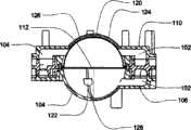
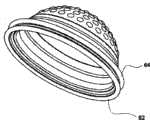
图1A为结合于盒实施例中的一种荚泵的实施例的剖视图;Figure 1A is a cross-sectional view of an embodiment of a pod pump incorporated into a cartridge embodiment;
图1B为结合于一些盒实施例中的一种荚泵的示范实施例的剖视图;Figure IB is a cross-sectional view of an exemplary embodiment of a pod pump incorporated in some cartridge embodiments;
图2A为结合一些于盒实施例中的一种气动控制阀的实施例的剖视示意图;Figure 2A is a schematic cross-sectional view of an embodiment of a pneumatic control valve incorporated in some cartridge embodiments;
图2B为结合一些于盒实施例中的另一种气动控制阀的实施例的剖视示意图;Figure 2B is a schematic cross-sectional view of another embodiment of a pneumatic control valve incorporated in some of the cartridge embodiments;
图2C为结合一些于盒实施例中的另一种气动控制阀的实施例的剖视示意图;Figure 2C is a schematic cross-sectional view of another embodiment of a pneumatic control valve incorporated in some of the cartridge embodiments;
图2D为结合一些于盒实施例中的另一种气动控制阀的实施例的剖视示意图;Figure 2D is a schematic cross-sectional view of another embodiment of a pneumatic control valve incorporated in some of the cartridge embodiments;
图2E-2F为阀隔膜的实施例的俯视及仰视图;2E-2F are top and bottom views of an embodiment of a valve diaphragm;
图2G所示的示意图为阀隔膜的一种实施例俯视及剖视图;The schematic diagram shown in FIG. 2G is a top view and a cross-sectional view of an embodiment of a valve diaphragm;
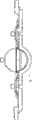
图3为盒中的荚泵的剖视图;Figure 3 is a cutaway view of a pod pump in a box;
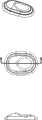
图4为盒中具有可变隔膜的荚泵的剖视图;Figure 4 is a cross-sectional view of a pod pump with a variable diaphragm in a cartridge;
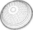
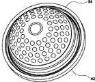
图4A和4B分别为盒中具有凹纹/可变隔膜的荚泵的俯视及剖视图;Figures 4A and 4B are top and cross-sectional views, respectively, of a pod pump with dimpled/variable diaphragms in the cartridge;
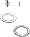
图4C和4D为具有可变表面的单环隔膜的示意图;4C and 4D are schematic diagrams of single-ring diaphragms with variable surfaces;
图5A-5D为可变隔膜的不同实施例的侧视图;5A-5D are side views of different embodiments of a variable diaphragm;
图5E-5H为测量泵隔膜的不同实施例的示意图;5E-5H are schematic diagrams of different embodiments of measuring pump diaphragms;
图6A和6B为具有光滑表面的双环隔膜的示意图;6A and 6B are schematic diagrams of double-ring diaphragms with smooth surfaces;
图6C和6D为具有凹纹表面的双环隔膜的示意图;6C and 6D are schematic diagrams of a double-ring diaphragm with a dimpled surface;
图6E和6F为具有可变表面的双环隔膜的示意图;Figures 6E and 6F are schematic diagrams of double-ring diaphragms with variable surfaces;
图6G为具有可变表面的双环隔膜的剖视图;Figure 6G is a cross-sectional view of a double ring diaphragm with a variable surface;
图7为显示用于致动一荚泵的气压致动系统的示意图;Figure 7 is a schematic diagram showing a pneumatic actuation system for actuating a pod pump;
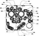
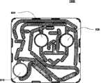
图8为盒的流体流通道的一个实施例的示意图;Figure 8 is a schematic diagram of one embodiment of a fluid flow channel of a cartridge;
图9为盒的一个替代实施例的流体通道的一个替代实施例的示意图;Figure 9 is a schematic diagram of an alternate embodiment of a fluid pathway of an alternate embodiment of a cartridge;
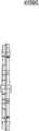
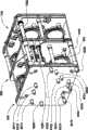
图10为根据图8指出的带有阀的盒的中片的传动侧的示范实施例的等比例主视图;Figure 10 is an isometric front view of an exemplary embodiment of the drive side of the middle piece of the cassette with valves indicated in accordance with Figure 8;
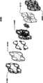
图11A为盒顶片外侧的示范实施例的前视等比例视图;Figure 11A is a front isometric view of an exemplary embodiment of the outside of the top sheet;
图11B为盒顶片内侧的示范实施例的前视等比例视图;Figure 1 IB is a front isometric view of an exemplary embodiment of the inside of the top sheet;
图11C为盒顶片的示范实施例的侧视图;Figure 11C is a side view of an exemplary embodiment of a box top sheet;
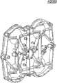
图12A为盒中片流体侧的示范实施例的前视等比例视图;Figure 12A is a front isometric view of an exemplary embodiment of the fluid side of a tablet-in-cassette;
图12B为盒中片气体侧的示范实施例的前视等比例视图;Figure 12B is a front isometric view of an exemplary embodiment of the air side of the sheet-in-cassette;
图12C为盒中片的示范实施例的侧视图;Figure 12C is a side view of an exemplary embodiment of a sheet-in-box;
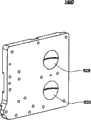
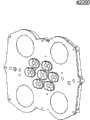
图13A为盒底片内侧的示范实施例的前视等比例视图;Figure 13A is a front isometric view of an exemplary embodiment of the inside of the box bottom;
图13B为盒底片外侧的示范实施例的前视等比例视图;Figure 13B is a front isometric view of an exemplary embodiment of the outside of the box bottom;
图13C为盒底片的示范实施例的侧视图;Figure 13C is a side view of an exemplary embodiment of a box bottom;
图14A为盒组装示范实施例的俯视图;Figure 14A is a top view of an exemplary embodiment of a cartridge assembly;
图14B为盒组装示范实施例的仰视图;Figure 14B is a bottom view of an exemplary embodiment of a cartridge assembly;
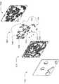
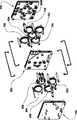
图14C为盒组装示范实施例的分解图;Figure 14C is an exploded view of an exemplary embodiment of a cartridge assembly;
图14D为盒组装示范实施例的分解图;Figure 14D is an exploded view of an exemplary embodiment of a cartridge assembly;
图15A-15C为盒组装示范实施例的剖视图;15A-15C are cross-sectional views of an exemplary embodiment of a cartridge assembly;
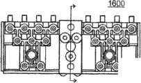
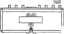
图16A显示根据盒替换实施例的顶片替换实施例的等比例俯视图;Figure 16A shows an isometric top view of an alternative embodiment of a top sheet according to an alternative embodiment of a cartridge;
图16B显示仰视图根据盒的替换实施例的顶片的替换实施例;Figure 16B shows an alternative embodiment of a top sheet according to an alternative embodiment of a box in bottom view;
图16C显示顶片替换实施例的侧视图;Figure 16C shows a side view of an alternative embodiment of the topsheet;
图17A显示根据盒替换实施例的中片替换实施例的等比例俯视图;Figure 17A shows a top isometric view of an alternative embodiment of a middle sheet according to an alternative embodiment of a cassette;
图17B显示根据盒替换实施例的中片替换实施例的等比例仰视图;Figure 17B shows an isometric bottom view of an alternative embodiment of a middle sheet according to an alternative embodiment of a cartridge;
图17C显示了中片替换实施例的侧视图;Figure 17C shows a side view of an alternate embodiment of the middle sheet;
图18A显示了根据盒替换实施例的底片替换实施例的等比例俯视图;Figure 18A shows a top isometric view of an alternative embodiment of a negative according to an alternative embodiment of a cartridge;
图18B显示了根据盒替换实施例的底片替换实施例的等比例仰视图;Figure 18B shows an isometric bottom view of an alternative embodiment of a negative according to an alternative embodiment of a cartridge;
图18C显示了底片替换实施例的侧视图;Figure 18C shows a side view of an alternate embodiment of the negative;
图19A为盒组装替换实施例的俯视图;Figure 19A is a top view of an alternative embodiment of a cartridge assembly;
图19B为盒组装替换实施例的分解视图;Figure 19B is an exploded view of an alternative embodiment of a cartridge assembly;
图19C为盒组装替换实施例的分解视图;Figure 19C is an exploded view of an alternative embodiment of a cartridge assembly;
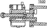
图20A-20B显示了盒组装替换实施例的剖视图;Figures 20A-20B show cross-sectional views of alternative embodiments of cartridge assembly;
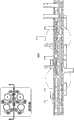
图38A为盒流体流通道的实施例的示意图;Figure 38A is a schematic illustration of an embodiment of a cartridge fluid flow channel;
图38B为盒流体流通道的替换实施例的示意图;Figure 38B is a schematic diagram of an alternate embodiment of a cartridge fluid flow channel;
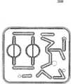
图39A和39B为盒示范实施例的顶片外侧示范实施例的等比例主视图;39A and 39B are isometric front views of an exemplary embodiment of the top sheet outside of an exemplary embodiment of a box;
图39C和39D为盒顶片内侧的示范实施例的等比例主视图;Figures 39C and 39D are isometric front views of an exemplary embodiment of the inside of the box top sheet;
图39E为盒示范实施例的顶片的侧视图;Figure 39E is a side view of the top sheet of an exemplary embodiment of a box;
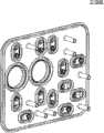
图310A和310B为盒中片液体侧的示范实施例的等比例主视图;Figures 310A and 310B are isometric front views of an exemplary embodiment of the liquid side of a tablet in a box;
图310C和310D为盒中片气体侧的示范实施例的等比例主视图;Figures 310C and 310D are isometric front views of an exemplary embodiment of the air side of the sheet-in-cassette;
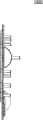
图310E为根据盒示范实施例的中片的侧视图;Figure 310E is a side view of a middle panel according to an exemplary embodiment of a cartridge;
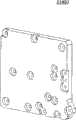
图311A和311B为根据盒示范实施例的底片内侧的等比例主视图;311A and 311B are isometric front views of the inside of the bottom sheet according to an exemplary embodiment of a cartridge;
图311C和311D为盒底片外侧的示范实施例的等比例主视图;Figures 311C and 311D are front isometric views of an exemplary embodiment of the outside of the box bottom;
图311E为根据盒示范实施例的底片的侧视图;Figure 31 IE is a side view of a bottom sheet according to an exemplary embodiment of a cartridge;
图312A为盒组装替换实施例的俯视图;Figure 312A is a top view of an alternative embodiment of a cartridge assembly;
图312B为盒组装替换实施例的仰视图;Figure 312B is a bottom view of an alternative embodiment of a cartridge assembly;
图312C为盒组装替换实施例的分解视图;Figure 312C is an exploded view of an alternative embodiment of a cartridge assembly;
图312D为盒组装替换实施例的分解视图;Figure 312D is an exploded view of an alternative embodiment of a cartridge assembly;
图313显示了盒组装替换实施例的剖视图;Figure 313 shows a cross-sectional view of an alternative embodiment of a cartridge assembly;
图314A和314B为盒顶片外侧替换实施例的等比例主视图;Figures 314A and 314B are isometric front views of alternative embodiments of the outside of the top sheet;
图314C和314D为盒顶片内侧替换实施例的等比例主视图;Figures 314C and 314D are isometric front views of alternative embodiments of the inside of the top sheet;
图314E为盒替换实施例的顶片的侧视图;Figure 314E is a side view of the top sheet of an alternative embodiment of the cartridge;
图315为根据盒替换实施例的顶片垫圈的主视图;Figure 315 is a front view of a top sheet gasket according to an alternative embodiment of the cartridge;
图316A和316B为盒中片液体侧的替换实施例的等比例主视图;Figures 316A and 316B are front isometric views of an alternate embodiment of the liquid side of a tablet in a box;
图316C和316D为盒中片气体侧的替换实施例的等比例主视图;Figures 316C and 316D are front isometric views of an alternative embodiment of the air side of the sheet in the cassette;
图316E为根据盒替换实施例的中片的侧视图;Figure 316E is a side view of a middle panel according to an alternative embodiment of a cartridge;
图317为主视图底片垫圈根据盒的替换实施例;Fig. 317 Front view. Alternative embodiment of the film gasket according to the cartridge;
图318A和318B为盒底片内侧的替换实施例的等比例主视图;Figures 318A and 318B are front isometric views of an alternative embodiment of the inside of the box bottom;
图318C和318D为盒底片外侧的替换实施例的等比例主视图;Figures 318C and 318D are isometric front views of alternative embodiments on the outside of the box bottom;
图318E为根据盒替换实施例的底片的侧视图;Figure 318E is a side view of a negative according to an alternative embodiment of a cartridge;
图319A为盒组装替换实施例的俯视图;Figure 319A is a top view of an alternative embodiment of a cartridge assembly;
图319B为盒组装替换实施例的仰视图;Figure 319B is a bottom view of an alternative embodiment of a cartridge assembly;
图319C为盒组装替换实施例的分解视图;Figure 319C is an exploded view of an alternative embodiment of a cartridge assembly;
图319D为盒组装替换实施例的分解视图;Figure 319D is an exploded view of an alternative embodiment of a cartridge assembly;
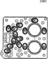
图320A-320B显示盒组装替换实施例的剖面视图;Figures 320A-320B show cross-sectional views of alternative embodiments of cartridge assembly;
图321A-321B显示了止回阀实施例的剖面视图;以及321A-321B show cross-sectional views of an embodiment of a check valve; and
图321C-321D显示了止回阀实施例的示意图;321C-321D show schematic diagrams of embodiments of check valves;
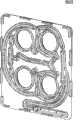
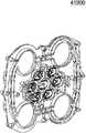
图48A为盒流体流通道的实施例的示意图;Figure 48A is a schematic illustration of an embodiment of a cartridge fluid flow channel;
图48B为盒流体流通道的替换实施例的示意图;Figure 48B is a schematic illustration of an alternate embodiment of a cartridge fluid flow channel;
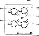
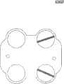
图49A为盒中片示范实施例的等比例仰视图;Figure 49A is an isometric bottom view of an exemplary embodiment of a tablet in a box;
图49B为盒中片示范实施例的等比例俯视图;Figure 49B is an isometric top view of an exemplary embodiment of a tablet in a box;
图49C为盒中片示范实施例的等比例仰视图;Figure 49C is an isometric bottom view of an exemplary embodiment of a tablet in a box;
图49D为盒中片示范实施例的侧视图;Figure 49D is a side view of an exemplary embodiment of a sheet-in-box;
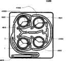
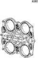
图410A-410B为盒示范实施例的顶片示范实施例的等比例俯视图;410A-410B are top isometric views of an exemplary embodiment of a top sheet of an exemplary embodiment of a cartridge;
图410C-410D为盒示范实施例的顶片示范实施例的等比例视图;Figures 410C-410D are isometric views of an exemplary embodiment of a top sheet of an exemplary embodiment of a cartridge;
图410E为盒顶片示范实施例的侧视图;Figure 410E is a side view of an exemplary embodiment of a box top sheet;
图411A和411B为盒示范实施例的底片示范实施例的等比例仰视图;411A and 411B are isometric bottom views of an exemplary embodiment of a negative of an exemplary embodiment of a cartridge;
图411C和411D为盒示范实施例的底片示范实施例的等比例俯视图;Figures 411C and 411D are isometric top views of an exemplary embodiment of a negative of an exemplary embodiment of a cartridge;
图411E为盒示范实施例的底片示范实施例的侧视图;Figure 41 IE is a side view of an exemplary embodiment of a negative of an exemplary embodiment of a cartridge;
图412A为盒组装替换实施例的顶片的等比例视图;Figure 412A is an isometric view of a top sheet of an alternative embodiment of a cartridge assembly;
图412B为盒组装替换实施例的底片的等比例视图;Figure 412B is an isometric view of the negative of an alternative embodiment of a cartridge assembly;
图412C为盒组装替换实施例的分解视图;Figure 412C is an exploded view of an alternative embodiment of a cartridge assembly;
图412D为盒组装替换实施例的分解视图;Figure 412D is an exploded view of an alternative embodiment of a cartridge assembly;
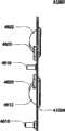
图413A-413C显示了盒组装替换实施例的剖面视图;Figures 413A-413C show cross-sectional views of alternative embodiments of cartridge assembly;
图414A-414B显示了根据盒替换实施例的顶片替换实施例的等比例俯视图;Figures 414A-414B show isometric top views of an alternative embodiment of a top sheet according to an alternative embodiment of a cartridge;
图414C-414D显示根据盒替换实施例的顶片替换实施例的等比例仰视图;Figures 414C-414D show isometric bottom views of an alternative embodiment of a top sheet according to an alternative embodiment of a cartridge;
图414E显示了顶片替换实施例的侧视图;Figure 414E shows a side view of an alternative embodiment of the top sheet;
图415A-415B显示了根据盒替换实施例的中片替换实施例的等比例俯视图;Figures 415A-415B show isometric top views of an alternative embodiment of a midsheet according to an alternative embodiment of a cartridge;
图415C-415D显示了根据盒替换实施例的中片替换实施例的等比例仰视图;Figures 415C-415D show isometric bottom views of an alternative embodiment of a midpiece according to an alternative embodiment of a cartridge;
图415E显示了中片替换实施例的侧视图;Figure 415E shows a side view of an alternate embodiment of the middle plate;
图416A-416B显示了根据盒替换实施例的底片替换实施例的等比例俯视图;Figures 416A-416B show isometric top views of an alternative embodiment of a film according to an alternative embodiment of a cartridge;
图416C-416D显示了根据盒替换实施例的底片替换实施例的等比例仰视图;Figures 416C-416D show isometric bottom views of an alternative embodiment of a negative according to an alternative embodiment of a cartridge;
图416E显示了底片替换实施例的侧视图;Figure 416E shows a side view of an alternate embodiment of the negative;
图417A为盒组装替换实施例的等比例俯视图;Figure 417A is an isometric top view of an alternative embodiment of a cartridge assembly;
图417B为盒组装替换实施例的等比例仰视图;Figure 417B is an isometric bottom view of an alternative embodiment of a cartridge assembly;
图417C为盒组装替换实施例的分解视图;Figure 417C is an exploded view of an alternative embodiment of a cartridge assembly;
图417D为盒组装替换实施例的分解视图;Figure 417D is an exploded view of an alternative embodiment of a cartridge assembly;
图417E显示了盒组装替换实施例的剖视图;Figure 417E shows a cross-sectional view of an alternative embodiment of a cartridge assembly;
图418A-418B显示了根据盒替换实施例的顶片替换实施例的等比例俯视图;Figures 418A-418B show isometric top views of an alternative embodiment of a top sheet according to an alternative embodiment of a cartridge;
图418C-418D显示了根据盒替换实施例的顶片替换实施例的等比例仰视图;Figures 418C-418D show isometric bottom views of an alternative embodiment of a top sheet according to an alternative embodiment of a cartridge;
图418E显示了顶片替换实施例的侧视图;Figure 418E shows a side view of an alternative embodiment of the top sheet;
图419A-419B显示了根据盒替换实施例的中片替换实施例的等比例俯视图;Figures 419A-419B show isometric top views of an alternative embodiment of a midsheet according to an alternative embodiment of a cartridge;
图419C-419D显示了根据盒替换实施例的中片替换实施例的等比例仰视图;Figures 419C-419D show isometric bottom views of an alternative embodiment of a middle sheet according to an alternative embodiment of a cartridge;
图419E显示了中片替换实施例的侧视图;Figure 419E shows a side view of an alternate embodiment of the middle plate;
图420A-420B显示了根据盒替换实施例的底片替换实施例的等比例俯视图;Figures 420A-420B show isometric top views of alternative embodiments of film according to alternative embodiments of cartridges;
图420C-420D显示了根据盒替换实施例的底片替换实施例的等比例仰视图;Figures 420C-420D show isometric bottom views of alternative embodiments of film according to cartridge alternative embodiments;
图420E显示了底片替换实施例的侧视图;Figure 420E shows a side view of an alternate embodiment of the negative;
图421A为盒组装替换实施例的俯视图;Figure 421A is a top view of an alternative embodiment of a cartridge assembly;
图421B为盒组装替换实施例的仰视图;Figure 42 IB is a bottom view of an alternative embodiment of a cartridge assembly;
图421C为盒组装替换实施例的分解视图;Figure 421C is an exploded view of an alternative embodiment of a cartridge assembly;
图421D为盒组装替换实施例的分解视图;Figure 42 ID is an exploded view of an alternative embodiment of a cartridge assembly;
图422A显示了盒组装替换实施例的剖视图;Figure 422A shows a cross-sectional view of an alternative embodiment of a cartridge assembly;
图422B显示了盒组装替换实施例的剖视图;Figure 422B shows a cross-sectional view of an alternative embodiment of a cartridge assembly;
图500A为混合盒盒系统示范实施例的分解视图;Figure 500A is an exploded view of an exemplary embodiment of a hybrid cartridge system;
图500B为混合盒盒系统示范实施例的分解视图;Figure 500B is an exploded view of an exemplary embodiment of a hybrid cartridge system;
图600A为中间盒盒系统示范实施例的分解视图;Figure 600A is an exploded view of an exemplary embodiment of a middlebox system;
图600B为中间盒盒系统示范实施例的分解视图;Figure 600B is an exploded view of an exemplary embodiment of a middlebox system;
图700A为平衡盒盒系统示范实施例的分解视图;Figure 700A is an exploded view of an exemplary embodiment of a balanced box system;
图700B为平衡盒盒系统示范实施例的分解视图;Figure 700B is an exploded view of an exemplary embodiment of a balanced box system;
图800A为组装盒系统替换实施例的主视图;Figure 800A is a front view of an alternative embodiment of the assembled cassette system;
图800B为组装盒系统替换实施例的等比例视图;Figure 800B is an isometric view of an alternative embodiment of the assembled cassette system;
图800C为组装盒系统替换实施例的等比例视图;Figure 800C is an isometric view of an alternative embodiment of the assembled cassette system;
图800D为组装盒系统替换实施例的分解视图;Figure 800D is an exploded view of an alternative embodiment of the assembled cassette system;
图800E为组装盒系统替换实施例的分解视图;Figure 800E is an exploded view of an alternative embodiment of the assembled cassette system;
图900A为荚盒系统示范实施例的等比例视图;Figure 900A is an isometric view of an exemplary embodiment of a pod system;
图900B为荚盒系统示范实施例的等比例视图;Figure 900B is an isometric view of an exemplary embodiment of a pod system;
图900C为荚盒系统示范实施例的侧视图;Figure 900C is a side view of an exemplary embodiment of a pod system;
图900D为荚盒系统一半的示范实施例的等比例视图;Figure 900D is an isometric view of an exemplary embodiment of one half of a pod system;
图900E为荚盒系统一半的示范实施例的等比例视图;Figure 900E is an isometric view of an exemplary embodiment of one half of a pod system;
图1000A为荚隔膜盒系统示范实施例的示意图;Figure 1000A is a schematic diagram of an exemplary embodiment of a pod septum cartridge system;
图1000B为荚隔膜盒系统示范实施例的示意图;Figure 1000B is a schematic diagram of an exemplary embodiment of a pod septum cartridge system;
图1100为荚盒系统示范实施例的分解视图;Figure 1100 is an exploded view of an exemplary embodiment of a pod system;
图1200为盒系统止回阀流体管线的实施例的分解视图;Figure 1200 is an exploded view of an embodiment of a cartridge system check valve fluid line;
图1300为盒系统止回阀流体管线的实施例的分解视图;Figure 1300 is an exploded view of an embodiment of a cartridge system check valve fluid line;
图1400为盒系统流体管线的示范实施例的等比例视图;Figure 1400 is an isometric view of an exemplary embodiment of a cartridge system fluid line;
图1500A为盒集成系统流体流通道的实施例的示意图;Figure 1500A is a schematic illustration of an embodiment of a cartridge integrated system fluid flow channel;
图1500B为盒集成系统流体流通道的实施例的示意图;以及Figure 1500B is a schematic illustration of an embodiment of a cartridge integrated system fluid flow channel; and
图1600A-F为根据本系统的一个实施例的连接气动管至歧管的模块的各种实施例。Figures 1600A-F are various embodiments of modules for connecting pneumatic tubes to manifolds, according to one embodiment of the present system.
具体实施方式Detailed ways
1.泵盒1. Pump box
1.1盒1.1 boxes
泵盒包括各种特征,即,荚泵、流体管线、以及一些实施例中的阀。本说明书中所显示和描述的盒实施例包括示例的以及替换的实施例。但是,任何具有相同功能的盒的变化也是可以预见的。同样地,尽管这里所描述的盒实施例按图8A和8B所示的流体图实施,在其它实施例中,该盒可具有不同的流体通道及/或阀门布置及数量,因而也落入本发明的保护范围内。The pump cassette includes various features, namely, the pod pump, fluid lines, and in some embodiments valves. The cartridge embodiments shown and described in this specification include exemplary as well as alternative embodiments. However, variations of any cartridges having the same function are also foreseeable. Likewise, while the cartridge embodiments described herein are implemented in accordance with the fluidic diagrams shown in FIGS. 8A and 8B , in other embodiments the cartridge may have a different arrangement and number of fluidic channels and/or valves and thus fall within the scope of this disclosure. within the scope of protection of the invention.
在示范的实施例中,该盒包括一顶片、一中片以及一底片。每种片体具有不同的实施例。总的来说,顶片包括泵腔和流体管线,中片包括互补的流体管线、计量泵和阀,而中片包括致动腔(在一些实施例中,顶片和中片包括平衡腔的互补部分)。In the exemplary embodiment, the box includes a top sheet, a middle sheet, and a bottom sheet. Each sheet has a different embodiment. In general, the top piece includes the pump chamber and fluid lines, the middle piece includes the complementary fluid lines, metering pumps and valves, and the middle piece includes the actuation chamber (in some embodiments, the top piece and the middle piece include the balance chamber. Complementary part).
总的来说,隔膜位于中片和底片之间,然而,对于平衡腔,一部分隔膜位于中片和顶片之间。一些实施例包括隔膜附接于盒的情况,以包覆成型、夹持、粘接、压合、焊接,或任何其它工艺或方法附接,然而,在示范的实施例中,该隔膜与顶片、中片和底片是分开的,直至这些片体组装起来。In general, the membrane is located between the middle and bottom panels, however, for the balance chamber, a portion of the membrane is located between the middle and top panels. Some embodiments include the case where the septum is attached to the cartridge by overmolding, clamping, gluing, pressing, welding, or any other process or method, however, in the exemplary embodiment, the septum is attached to the top The sheet, middle sheet and back sheet are separated until the sheets are assembled.
该盒可以用各种不同材料构成。通常,在各种实施例中,所用的材料为固体及非弹性的。在优选的实施例中,这些片体由聚砜构成,但在其它实施例中,该盒由任何固体材料构成,在示范实施例中,由热塑性塑料或热固性塑料构成。The box can be constructed from a variety of different materials. Generally, in various embodiments, the materials used are solid and non-elastic. In a preferred embodiment, the sheets are constructed of polysulfone, but in other embodiments, the cartridge is constructed of any solid material, in exemplary embodiments, thermoplastic or thermosetting plastic.
在示范的实施例中,该盒通过将隔膜放入其正确位置来组成,将片体按序组装并连接片体。在一个实施例中,这些片体是用激光焊接技术连接的。然而,在另一些实施例中,这些片体可以是粘接的、机械固定的、捆绑在一起的、超声焊接的、或者其它将这些片体附接的方式。In the exemplary embodiment, the cassette is constructed by placing the septum in its correct position, assembling the sheets in sequence and connecting the sheets. In one embodiment, the sheets are joined using laser welding techniques. However, in other embodiments, the sheets may be glued, mechanically secured, bound together, ultrasonically welded, or otherwise attached.
实际上,该盒可以用于从任何源向任何位置泵送任何种类的流体。这些种类的流体包括营养的、非营养的、无机化学物的、有机化学物的、体液的或任何其它类型液体。另外,流体在一些实施例中包括一种气体,因此,在一些实施例中,该盒用于泵送一种气体。In fact, the cartridge can be used to pump any kind of fluid from any source to any location. These types of fluids include nutritional, non-nutritional, inorganic chemical, organic chemical, bodily fluids or any other type of liquid. Additionally, the fluid includes a gas in some embodiments, and thus, in some embodiments, the cartridge is used to pump a gas.
该盒用于自所要的位置或至所要的位置泵送及引导流体。在一些实施例中,外部的泵将流体泵送至该盒而该盒将流体泵送至外部。然而,在一些实施例中,荚泵用于将流体吸入盒并将流体泵送到盒外部。The cartridge is used to pump and direct fluid from or to a desired location. In some embodiments, an external pump pumps fluid to the cassette and the cassette pumps fluid externally. However, in some embodiments, a pod pump is used to draw fluid into the cassette and pump fluid out of the cassette.
如上所述,根据阀的位置,对流体通道给予控制。因此,处于不同位置的阀或附加的阀为这一盒的替换实施例。另外,图中所示的流体管线和通道仅为这些流体管线和通道的例子。其它实施例可能有更多、更少及/或不同的流体通道。在还有另一些实施例中,该盒中可能不存在阀。As mentioned above, depending on the position of the valve, control is given to the fluid passage. Therefore, valves in different positions or additional valves are alternative embodiments for this cassette. In addition, the fluid lines and passages shown in the figures are only examples of such fluid lines and passages. Other embodiments may have more, fewer and/or different fluid channels. In still other embodiments, there may be no valve present in the cartridge.
这里所描述的荚泵数量可能还根据实施例而不同。例如,尽管上述显示及描述的示范及替换实施例包括两个荚泵,在另一个实施例中,该盒包括一个荚泵。在还有另一些实施例中,该盒包括多于两个荚泵。荚泵可以是单个的泵或者一前一后工作以提供更连续的流。任一种或两种都可用于该盒的各种实施例中。The number of pod pumps described here may also vary according to the embodiment. For example, while the exemplary and alternative embodiments shown and described above include two pod pumps, in another embodiment, the cassette includes one pod pump. In still other embodiments, the cassette includes more than two pod pumps. The pod pumps can be a single pump or work in tandem to provide a more continuous flow. Either or both can be used in various embodiments of the cartridge.
不同的流体入口和流体出口为流体端口。实际上,根据阀装置和控制,一流体入口可以是一流体出口。因此,流体端口指定为流体入口或流体出口只是出于描述的目的。各种实施例具有可以互换的流体端口。流体端口是设来给予特定流体通至盒的通道。这些流体端口不必同时使用,而是在实际中由不同的流体端口提供对盒的灵活使用。The different fluid inlets and fluid outlets are fluid ports. In practice, a fluid inlet can be a fluid outlet, depending on the valve arrangement and controls. Accordingly, designation of a fluid port as a fluid inlet or a fluid outlet is for descriptive purposes only. Various embodiments have fluid ports that are interchangeable. Fluid ports are provided to give access to specific fluids to the cartridge. These fluid ports do not have to be used at the same time, but in practice different fluid ports provide flexible use of the cartridge.
1.2示范压力荚泵实施例1.2 Demonstration Pressure Pod Pump Embodiment
图1A为结合于流体控制或泵盒(还可见于图3和4)中的示范荚泵100的剖视图,根据盒的示范实施例。在这个实施例中,荚泵由三个刚性片体组成,即“顶”片106,中片108,以及“底”片110(应当注意到的是术语“顶”和“底”为相对的,且在此为便于参照图1A所示的方向使用)。该顶和底片106和110主要包括组合在一起时组成一个球形腔室,就是一个荚泵的半球形部分。Figure 1A is a cross-sectional view of an
隔膜112将荚泵的中心穴分隔为两个腔室。在一个实施例中,这些腔室为:接收需要泵送的流体的泵室,以及接收控制气体以气压致动泵的致动室。入口102让流体进入该泵室,出口104让流体流出该泵室。入口102和出口104可以形成于中片108和顶片106之间。气动压力通过气压端口114提供任一种力,在正气体压力下,使隔膜112顶在荚泵空穴内的一面侧壁上令泵室的体积最小,或在负气体压力下,使隔膜112吸向荚泵100空穴另一侧壁令泵室的体积最大。A
隔膜112设有一个加厚的边116,紧密地由一凸出部118固定在中片108中。因此在制造中,在底片110被连接至(在示范的实施例中)中片108之前,隔膜112可以被放在并固定在沟槽108。The
尽管没有在图1A和1B中显示,在荚泵的一些实施例中,在流体侧,腔壁上设有一沟槽。该沟槽所起的作用是防止隔膜上的折痕在清空时捕捉腔室中的液体时。Although not shown in FIGS. 1A and 1B , in some embodiments of the pod pump, on the fluid side, the chamber wall is provided with a groove. This groove serves to prevent the creases in the diaphragm from catching liquid in the chamber when it is emptying.
首先参考图1,显示了盒中的一个往复式容积泵100的剖面示意图。该荚泵100包括一弹性隔膜112(也称为“泵隔膜”或“隔膜”),安装在泵腔(也称为“液体腔”或“液体泵腔”)壁122与致动腔(也称为“气动腔”)壁120交界之处。隔膜112有效地将内部空穴分为一个容积可变泵腔(由泵腔壁122的刚性内表面与隔膜112的表面界定)和一个互补的容积可变致动腔(由致动腔壁120的刚性内表面与隔膜112的表面界定)。上部106包括一流体入口102和一流体出口104,两者都与泵/液体腔流体连通。底部110包括一致动或气压接口114,与致动腔流体连通。正如下面详细讨论的,隔膜112可被交替施加负压或在气动接口114通大气压与正气压,而在该空穴中前后推移。在隔膜112前后往返时,泵送及致动腔的容积和保持恒定。Referring first to FIG. 1 , a schematic cross-sectional view of a reciprocating
在通常的泵送操作中,在致动或气压接口114施加负压或通大气压的气动压力将隔膜112吸向致动腔壁120,使泵/液体腔延伸并将液体通过入口102吸入泵腔,当施加的正气压倾向于将隔膜112推至泵腔壁122,使泵腔坍缩并通过出口104排出泵腔中的液体。在这个泵送操作中,泵腔壁122的内表面与致动腔壁120限定了隔膜112前后往返的移动。在图1A所示的实施例中,泵腔壁122和致动腔壁120的内表面为刚性、平滑、和半球形的。代替刚性致动室壁120,一种可选择的刚性限定结构-例如,用于提供气动压力的一部分卡缘及/或一组肋条-可用于限制隔膜当泵腔接近最大值时的移动。卡缘和肋条结构主要在提交于2003年10月30日申请号10/697,450题为“气动控制的卡缘组件”、且公开号为US 2005/0095154(代理文号为1062/D75)的美国专利申请,和提交于2004年10月29日申请号为PCT/US2004/035952题为“气动控制的卡缘组件”、且公开号为WO 2005/044435(代理文号为1062/D71WO)的相关PCT申请,两者整体援引于此作为参考。因此,刚性结构-例如刚性致动室壁120,一卡缘,或一组肋条-界定了隔膜112在腔室处于其最大值时的形状。在一个较佳实施例中,隔膜112(被推顶至刚性限制结构时)与泵腔壁122的刚性内表面界定了泵腔容积处于最小时的球形泵腔容积。In normal pumping operation, application of negative or atmospheric pneumatic pressure at the actuation or
这样,在图1A所示的实施例中,隔膜112的移动受泵腔壁122和致动腔壁122的限制。只要通过气动接口114所提供的正压及通大气压或者负压足够强,隔膜112将从受致动腔壁120限制的位置移动到受泵腔壁122限制的位置。当隔膜112被推向致动腔壁120时,隔膜和泵腔壁122界定泵腔的最大容积。当隔膜被推向泵腔壁122时,泵腔处于其最小容积。Thus, in the embodiment shown in FIG. 1A , the movement of the
在示范实施例中,泵腔壁122和致动腔壁120都具有半球形状,所以泵腔在其最大容积时为球形形状。通过利用在最大容积时达到球状体-特别是圆球形形状-的泵腔,循环流可得以贯穿整个泵腔。因此这种形状倾向于可以避免泵腔内的滞留区。如下面进一步讨论的,入口102和出口104的方向还倾向于对通过泵腔的流体流有影响,并在一些实施例中,减少流体滞留区形成的概率。另外,与其它空间形状相比较,圆球形形状(及一般的球状体形状)倾向于在流体循环进入、通过、及流出泵室时产生更少的剪切和紊流。In the exemplary embodiment, both the
现参考图3-4,显示泵腔中的凸起流通道30。这个凸起流通道30允许流体在隔膜到达行程终了之后连续通过荚泵。这样,凸起流通道30使隔膜导致空气或流体被捕获于荚泵中或该隔膜堵塞荚泵的入口或出口而抑制连续流的可能性降低到最少。示范的实施例中所示的凸起流通道30具有特定的大小,然而,在可选的实施例中,如图18A-18E所见,凸起流通道30较窄,或者在还有另一些实施例中,凸起流通道30可以是任何大小,其目的是控制流体流量以实现所需要的流速或流体方式。这样,这里关于凸起流通道、荚泵、阀或任何其它方面所描述和显示的大小仅为示范性及可选的实施例。其它实施例是容易显现的。Referring now to Figures 3-4, the raised flow channel 30 in the pump chamber is shown. This raised flow channel 30 allows fluid to continue through the pod pump after the diaphragm reaches end-of-stroke. In this way, the raised flow channel 30 minimizes the possibility of the diaphragm causing air or fluid to become trapped in the pod pump or the diaphragm blocking the inlet or outlet of the pod pump, inhibiting continuous flow. The raised flow channel 30 shown in the exemplary embodiment has a specific size, however, in alternative embodiments, as seen in FIGS. 18A-18E , the raised flow channel 30 is narrower, or in still other In embodiments, the raised flow channel 30 may be of any size, the purpose of which is to control fluid flow to achieve a desired flow rate or fluid pattern. As such, dimensions described and shown herein with respect to raised flow channels, pod pumps, valves, or any other aspect are exemplary and optional embodiments only. Other embodiments are readily apparent.
1.3示范性平衡荚实施例1.3 Exemplary Balancing Pod Embodiment
现参考图1B,显示了平衡荚的示范实施例。该平衡荚的结构与上面关于图1A所描述的荚泵类似。然而,一平衡荚包括两个流体平衡腔,而不是一个致动腔和一个泵腔,并且不包括致动端口。另外,每个平衡腔包括一入口102和一出口104。在示范的实施例中,每个平衡腔壁120、122包括一沟槽126。下面将进一步详细描述该沟槽126。Referring now to FIG. 1B , an exemplary embodiment of a balancing pod is shown. The balance pod is similar in structure to the pod pump described above with respect to Figure 1A. However, a balance pod includes two fluid balance chambers instead of an actuation chamber and a pump chamber, and does not include an actuation port. Additionally, each balancing chamber includes an
在两个腔室之间设有隔膜112。平衡腔的工作是平衡流体流入及流出腔室的流量,使两个腔保持相等的容积速率流量。尽管显示了每个腔的入口102和出口104位于同一侧,在另一个实施例中,每个腔的入口102和出口104在不同侧。还有,入口102和出口104可以在任何一侧,根据平衡泵所结合的流体通道。在平衡荚的一个实施例中,隔膜112包括一个与下面在图6A-6G中所描述的相类似的实施例。然而,在另一可选实施例中,隔膜112可以包覆成型或者构造成不使用双环密封的结构。A
1.4计量泵和流体管理系统1.4 Metering pumps and fluid management systems
计量泵可以是任何能够加入任何流体或去除任何流体的泵。这些流体包括但不限于药物、无机化合物或元素、有机化合物或元素、营养药品、营养元素或化合物或溶液、或任何其它能够被泵送的流体。在一个实施例中,该计量泵为一种隔膜泵。在示范的实施例中,该计量泵为小容积荚泵。在示范的实施例中,该计量泵包括一入口和一出口,与大型荚泵(例如图1A所示)相类似。然而,入口和出口一般比荚泵小,且在一个示范的实施例中,包括一种火山型(volcano)阀的凸环围绕于入口或出口。计量泵包括一隔膜,各种计量泵隔膜的实施例如图5E-5H所示。该计量泵,在一些实施例中,将一定容积的流体泵到流体管线之外。一旦流体处于荚泵之内,位于盒外部的基准腔室,利用FMS技术确定被去除的体积。A metering pump can be any pump capable of adding any fluid or removing any fluid. These fluids include, but are not limited to, drugs, inorganic compounds or elements, organic compounds or elements, nutraceuticals, nutritional elements or compounds or solutions, or any other fluid capable of being pumped. In one embodiment, the metering pump is a diaphragm pump. In the exemplary embodiment, the metering pump is a small volume pod pump. In the exemplary embodiment, the metering pump includes an inlet and an outlet, similar to a large pod pump (such as that shown in FIG. 1A ). However, the inlet and outlet are generally smaller than pod pumps, and in one exemplary embodiment, a raised ring comprising a volcano valve surrounds the inlet or outlet. The metering pump includes a diaphragm, and various embodiments of metering pump diaphragms are shown in Figures 5E-5H. The metering pump, in some embodiments, pumps a volume of fluid out of the fluid line. Once the fluid is within the pod pump, a reference chamber located outside the cartridge, the volume removed is determined using FMS techniques.
这样,根据该实施例,这个被去除的流体流量随后流至流体出口、平衡腔或荚泵。这样,在一些实施例中,计量泵用于从一个流体管线中去除一定量的流体。在另一个实施例中,计量泵用于去除一定量的流体以产生其它结果。Thus, depending on the embodiment, this removed fluid flow then flows to the fluid outlet, balance chamber or pod pump. Thus, in some embodiments, a metering pump is used to remove a volume of fluid from a fluid line. In another embodiment, a metering pump is used to remove an amount of fluid to produce other results.
可以利用FMS方法进行某种流体管理系统测量,如,举例来说,测量一个隔膜行程中通过泵腔泵送的对象流体的体积或者检测泵腔中存在的空气,如,利用专利号4,808,161;4,826,482;4,976,162;5,088,515;以及5,350,357中所描述的美国专利,这些均作为参考整体援引于此。FMS methods can be used to make certain fluid management system measurements such as, for example, measuring the volume of subject fluid pumped through a pump chamber during one diaphragm stroke or detecting the presence of air in a pump chamber, such as using Patent Nos. 4,808,161; 4,826,482 4,976,162; 5,088,515; and 5,350,357, all of which are incorporated herein by reference in their entirety.
计量泵还用于各种实施例中将第二流体泵送至流体管线中。在一些实施例中,计量泵用于将一种治疗药物或一种化合物泵送至一个流体管线中。一个实施例利用计量泵泵送一定量的化合物至混合室以便配成一种溶液。在这些实施例中的一些,计量泵设置成用于进行FMS体积测量。在另一个实施例中,该计量泵则不是。A metering pump is also used in various embodiments to pump a second fluid into the fluid line. In some embodiments, a metering pump is used to pump a therapeutic drug or a compound into a fluid line. One embodiment utilizes a metering pump to pump an amount of compound to a mixing chamber to make a solution. In some of these embodiments, a metering pump is configured to take FMS volume measurements. In another embodiment, the metering pump is not.
对于FMS测量,一种小的固定基准气腔位于盒的外部,例如,在气动歧管中(未显示)。一阀将基准腔与一个第二压力传感器相隔离。计量泵的行程体积可以通过对基准腔冲气,测量其压力,然后打开至泵腔的阀门来精确计算。腔侧的气体的体积可以基于基准腔的固定体积以及该基准腔连接至泵腔时的压力的变化来计算。For FMS measurements, a small fixed reference air cavity is located outside the box, for example, in a pneumatic manifold (not shown). A valve isolates the reference chamber from a second pressure sensor. The stroke volume of a metering pump can be accurately calculated by filling the reference chamber, measuring its pressure, and then opening the valve to the pump chamber. The volume of gas on the chamber side can be calculated based on the fixed volume of the reference chamber and the change in pressure when this reference chamber is connected to the pump chamber.
1.5阀1.5 valve
盒的示范实施例包括一个或多个阀。阀是用于通过开启和关闭流体管线来调节流量。盒中的各种实施例中所包含的这些阀包括以下一种或多种:火山型(volcano)阀或光滑阀。在一些盒实施例中,可包含止回阀。火山型(volcano)阀的实施例显示于图2A和2B,而光滑阀的一个实施例显示于图2C中。另外,图3和4显示了位于一盒中设有一入口和一出口阀的荚泵实施例的剖视图。Exemplary embodiments of cartridges include one or more valves. Valves are used to regulate flow by opening and closing fluid lines. The valves included in various embodiments of the cartridge include one or more of: a volcano valve or a smooth valve. In some cartridge embodiments, a check valve may be included. Embodiments of a volcano valve are shown in Figures 2A and 2B, while an embodiment of a smooth valve is shown in Figure 2C. Additionally, Figures 3 and 4 show cross-sectional views of an embodiment of a pod pump located in a cassette with an inlet and an outlet valve.
一般而言,刚才所描述的类型的往复式容积泵可包括各种阀,或与之一起使用,阀通过泵控制流体流。因此,比如,往复式容积泵或平衡泵可包括,一入口阀及/或一出口阀,或与之一起使用。该阀可以为被动或主动式。在往复式容积泵的示范实施例中,隔膜被一种气体的正负压、或被正压及通大气压作用而前后推移,这种气体通过将致动腔连接至压力致动系统的气压端口提供。所产生的隔膜往复运动将流体从入口吸入泵腔(出口阀防止液体从出口吸回泵腔),然后通过出口将流体泵送到泵腔外部(入口阀防止流体从入口顶回来)。In general, reciprocating positive displacement pumps of the type just described may include, or be used with, various valves that control the flow of fluid through the pump. Thus, for example, a reciprocating positive displacement or balancing pump may include, or be used with, an inlet valve and/or an outlet valve. The valve can be passive or active. In the exemplary embodiment of a reciprocating positive displacement pump, the diaphragm is moved back and forth by positive and negative pressure, or by positive and atmospheric pressure, of a gas that passes through a pneumatic port that connects the actuation chamber to the pressure actuation system. supply. The resulting reciprocating motion of the diaphragm draws fluid from the inlet into the pump chamber (the outlet valve prevents fluid from being sucked back into the pump chamber from the outlet), and then pumps fluid out of the pump chamber through the outlet (the inlet valve prevents fluid from being pushed back from the inlet).
在示范的实施例中,主动阀控制通过泵和盒的流体流。主动阀可以由一个控制器以一种令流体按需要的方向引导的方式来致动。这种装置一般允许控制器使流以任一方向通过荚泵。在典型的系统中,该流通常在第一方向,例如,从入口至出口。在某些其它时候,该流可以导向相反方向,例如,从出口至入口。这种流的逆行可以用来,例如,在泵的预灌中,检查异常管线情况(例如,一种管线堵塞、阻碍、断开、或泄漏),或清除异常管线情况(例如,试着驱除阻碍)。In the exemplary embodiment, active valves control fluid flow through the pump and cartridge. Active valves can be actuated by a controller in such a way that fluid is directed in a desired direction. Such devices generally allow the controller to direct flow through the pod pump in either direction. In a typical system, the flow is generally in a first direction, eg, from inlet to outlet. At some other times, the flow may be directed in the opposite direction, eg, from outlet to inlet. This retrograde flow can be used, for example, in priming a pump, to check for an abnormal line condition (e.g., a line blockage, obstruction, disconnect, or leak), or to clear an abnormal line condition (e.g., to try to expel hinder).
阀气压致动提供压力控制以及在系统中产生对压力的自然限制。在一个系统的上下文中,气压致动对提供将螺管控制阀设置在系统一侧远离流体通道的位置的机会带来的增加的好处。Pneumatic actuation of the valve provides pressure control as well as creating a natural limit to pressure in the system. In the context of a system, pneumatic actuation has the added benefit of providing the opportunity to locate the solenoid control valve on one side of the system away from the fluid passage.
现参考图2A和2B,显示了一种火山型阀剖视图实施例的剖视图。该火山型阀为可用于盒实施例中的气压控制阀。沿着中片204的隔膜202界定了一个阀腔206。通过气动口208提供气动压力,或以正气体压,迫使隔膜202顶在一阀座210以关闭该阀,或以负气体压,或在一些实施例中,以通大气压,来将隔膜从阀座210吸入以打开该阀。一种控制气体腔212由隔膜202、顶片214、以及中片204界定。中片204上形成缺口,隔膜202位于该缺口中,从而在隔膜202的一侧形成控制气体腔212并在另一个侧形成阀腔206。Referring now to Figures 2A and 2B, a cross-sectional view of an embodiment of a volcano-type valve in cross-section is shown. The volcano valve is an air pressure control valve that may be used in cartridge embodiments.
气压端口208是由顶片214中的一条槽界定的。通过对盒中的数个阀提供气压控制,这些阀可以联在一起使所有联起来的阀可通过单一的气压源同时开启或关闭。形成于中片204中的槽,对应于沿着底片216界定的流体通道,定义了阀入口218和阀出口220。穿过中片204所形成的孔提供入口218与阀腔206之间,以及阀腔206与出口220之间的流通。
隔膜202设有加厚的边缘222,该边紧密地固定于中片204的沟槽224中。这样,隔膜202可以在顶片214连接至中片204之前放入并固定在沟槽224中。这样,这种阀设计可在制造中带来好处。如图2B和2C所示,顶片214可包括延伸至控制气体腔212的额外材料,以防止隔膜202在远离沟槽224的方向被推得太过,使隔膜的加厚边缘222不会从沟槽224中跳出来。气动端口208相对于控制气体腔212的位置如图2A和2B中所示的两个实施例变化。The
图2C显示了一种实施例,其阀腔缺少阀座的特征。而且,在图2C中,这个实施例中的阀不包括任何火山型特征,因此阀腔206,即,流体侧,不包括任何高出的特征,所以是光滑的。这个实施例在用于泵送对剪切敏感的流体的盒中使用。图2D显示了一种实施例,其中阀腔具有辅助密封阀隔膜的高出区域。现参考图2E-2G,显示了阀隔膜的不同实施例。尽管显示和描述了一些示范的实施例,在另一些实施例中,可以采用不同变型的阀以及阀隔膜。Figure 2C shows an embodiment where the valve cavity lacks the features of the valve seat. Also, in Figure 2C, the valve in this embodiment does not include any volcano-type features, so the
1.6荚隔膜的示范实施例1.6 Exemplary Embodiment of Pod Septa
在一些实施例中,隔膜具有可变剖面厚度,如图4所示。较薄的、较厚的、或可变厚度的隔膜可以用来调节适应被选择隔膜材料的强度、弹性及其它特性。较薄的、较厚的、或可变厚度的隔膜壁厚度还可以用于控制隔膜,使得其一些区域比另一些区域更有弹性,从而辅助对泵送动作以及泵腔中等的对象流体流的控制。在这个实施例中显示隔膜在靠近其中心位置具有最厚的剖面区域。然而在另一些具有可变剖面的隔膜的实施例中,这些最厚及最薄区域可以在隔膜的任何位置。因此,例如,剖面较薄者位于近隔膜中心的位置而剖面较厚者位于近隔膜周边位置。还有其它构造也是可能的。参考图5A-5D,显示了一种隔膜实施例具有不同的表面实施例,这些包括光滑的(图5A),环状的(图5D),有肋条的(图5C),有不同厚度的凹洞或圆点的(图5B),以及位于隔膜致动及或泵送侧不同几何位置的。在一种隔膜实施例中,该隔膜在至少一个剖面上具有切线斜面,但在另一个实施例中,该隔膜完全光滑或基本上光滑。In some embodiments, the membrane has a variable cross-sectional thickness, as shown in FIG. 4 . Thinner, thicker, or variable thickness membranes can be used to tailor the strength, elasticity, and other properties of the selected membrane material. Thinner, thicker, or variable thickness diaphragm wall thicknesses can also be used to control the diaphragm so that some regions thereof are more elastic than others, thereby aiding in the control of the pumping action and flow of subject fluid in the pump chamber etc. control. In this example the diaphragm is shown to have the thickest cross-sectional region near its center. However, in other embodiments of the membrane having a variable profile, these thickest and thinnest regions may be anywhere on the membrane. Thus, for example, thinner sections are located near the center of the septum and thicker sections are located near the periphery of the septum. Still other configurations are possible. Referring to Figures 5A-5D, there is shown a membrane embodiment with different surface embodiments, these include smooth (Figure 5A), annular (Figure 5D), ribbed (Figure 5C), concave with different thicknesses. holes or dots (Fig. 5B), and in different geometric locations on the actuating and/or pumping side of the diaphragm. In one embodiment of the membrane, the membrane has a tangential slope in at least one section, but in another embodiment, the membrane is completely smooth or substantially smooth.
现参考图4A、4C和4D,显示隔膜的一种替换实施例。在这个实施例中,隔膜设有凹洞或圆点表面。Referring now to Figures 4A, 4C and 4D, an alternate embodiment of a diaphragm is shown. In this embodiment, the diaphragm is provided with a dimpled or dotted surface.
隔膜可用任何具有所需要的使用寿命及与对象流体兼容的任何弹性材料。隔膜可以由任何对流体、液体或气体具有弹性的材料制成。隔膜材料还可以选择由隔膜来泵送或引入腔室以利隔膜移动的具有特定生物兼容性、温度兼容性或对不同对象流体具有兼容性的材料。在示范的实施例中,隔膜由高延展性的硅树脂制成。The diaphragm can be any elastomeric material that has the desired useful life and is compatible with the subject fluid. The diaphragm can be made of any material that is resilient to fluids, liquids or gases. The membrane material may also be selected to have specific biocompatibility, temperature compatibility, or compatibility with different subject fluids to be pumped by the membrane or introduced into the chamber to facilitate movement of the membrane. In the exemplary embodiment, the diaphragm is made of highly ductile silicone.
但在另一些实施例中,隔膜是由任何人造橡胶或橡胶制成,包括但不限于,硅树脂、聚氨酯橡胶、腈、EPDM或任何其它橡胶、人造橡胶或弹性材料。But in other embodiments, the diaphragm is made of any elastomer or rubber including, but not limited to, silicone, urethane rubber, nitrile, EPDM, or any other rubber, elastomer or elastomeric material.
隔膜的形状取决于多种因数。这些因数包括但不限于:腔室的形状;腔室的大小;对象流体特征;每行程泵送的对象流体体积;以及将隔膜附接至壳体的方法或方式。隔膜的大小取决于多种因数。这些因数包括但不限于:腔室的形状;腔室的大小;对象流体特征;每行程泵送的对象流体体积;以及将隔膜附接至壳体的方法或方式。因而,根据这些或其它因数,隔膜的形状和大小在不同实施例中不同。The shape of the diaphragm depends on a variety of factors. These factors include, but are not limited to: shape of the chamber; size of the chamber; subject fluid characteristics; subject fluid volume pumped per stroke; and method or manner of attaching the diaphragm to the housing. The size of the diaphragm depends on a variety of factors. These factors include, but are not limited to: shape of the chamber; size of the chamber; subject fluid characteristics; subject fluid volume pumped per stroke; and method or manner of attaching the diaphragm to the housing. Thus, depending on these or other factors, the shape and size of the diaphragm will vary in different embodiments.
隔膜可具有任何厚度。但在一些实施例中,其厚度范围介于0.002英寸至0.125英寸之间。基于隔膜所使用的材料,所需的厚度可不同。在一些实施例中,采用厚度范围介于0.015英寸与0.050英寸之间的高延展性的硅树脂。然而在另一些实施例中,厚度可不同。The membrane can be of any thickness. However, in some embodiments, the thickness ranges from 0.002 inches to 0.125 inches. Depending on the material used for the diaphragm, the required thickness can vary. In some embodiments, a high ductility silicone is used with a thickness ranging between 0.015 inches and 0.050 inches. In other embodiments, however, the thickness may vary.
在示范的实施例中,隔膜是预制的,包括在隔膜的至少一部分基本上为圆拱形的隔膜。圆拱形隔膜的一个实施例如图4E和4F所示。再者,该圆拱的大小基于上述一些或更多的因数而不同。然而,在另一个实施例中,隔膜可不包括预制的圆拱形状。In an exemplary embodiment, the membrane is prefabricated, including a substantially dome-shaped membrane in at least a portion of the membrane. One embodiment of a domed septum is shown in Figures 4E and 4F. Again, the size of the dome varies based on some or more of the above factors. However, in another embodiment, the diaphragm may not include a preformed domed shape.
在该示范实施例中,隔膜圆拱是以液体注塑方法制成的。而在另一些实施例中,该圆拱可以压缩铸模方法形成。在替换实施例中,该隔膜基本上为平的。在另一些实施例中,圆拱大小、宽度或高度可不同。In the exemplary embodiment, the diaphragm domes are formed by liquid injection molding. In yet other embodiments, the domes may be formed by compression molding. In an alternative embodiment, the membrane is substantially flat. In other embodiments, the domes may vary in size, width or height.
在不同的实施例,隔膜可通过各种方法和方式固定在位。在一个实施例中,隔膜夹在盒的两部分之间,而在一些这些实施例中,盒的边缘可包括卡住隔膜的特征。在另一些这些实施例中,隔膜是用至少一个螺栓或其它装置夹在盒上的。在另一些实施例中,隔膜是以一片塑料包覆成型的,然后再焊接该塑料或以别的方式附接至盒。在另一实施例中,隔膜夹在图1A和1B所示的中片和底片之间。尽管描述了一些将隔膜附接于盒的实施例,还可以采用任何方法或方式将隔膜附接至盒。在一个替换实施例中,该隔膜直接附接至盒的一部分。在一些实施例中,隔膜夹在片体之间的边缘比隔膜的其它区域厚。在一些实施例中,这个较厚区域为垫圈,在一些实施例中为O形环、环或其它任何形状的垫圈。再参考图6A-6D,显示了具有两个垫圈62、64的一种隔膜实施例。在一些这些实施例中,垫圈62、64提供了将隔膜附接至盒的附接点。在另一个实施例中,隔膜包括两个以上的垫圈。在一些实施例中还有带一个垫圈的隔膜(见图4A-4D)。In different embodiments, the membrane can be held in place by various methods and means. In one embodiment, the septum is sandwiched between two parts of the cartridge, while in some of these embodiments, the edges of the cartridge may include features that capture the septum. In other of these embodiments, the membrane is clamped to the cartridge by at least one bolt or other means. In other embodiments, the membrane is overmolded from a single piece of plastic, which is then welded or otherwise attached to the cartridge. In another embodiment, the membrane is sandwiched between the middle and bottom sheets shown in Figures 1A and 1B. Although some embodiments are described in which the membrane is attached to the cartridge, any method or manner of attaching the membrane to the cartridge may be used. In an alternative embodiment, the membrane is directly attached to a portion of the cartridge. In some embodiments, the edges of the membrane sandwiched between the sheets are thicker than other regions of the membrane. In some embodiments, this thicker region is a gasket, in some embodiments an O-ring, a ring, or any other shape of gasket. Referring again to FIGS. 6A-6D , one embodiment of a diaphragm having two
在一些垫圈的实施例中,该垫圈与隔膜邻接。然而,在另一些实施例中,垫圈是与隔膜分开的一个部分。在一些实施例中,垫圈是以与隔膜同样的材料制成的。然而,在另一个实施例中,垫圈是由与隔膜不同的材料制成的。在一些实施例中,垫圈是通过在隔膜上面包覆成型一环来制成。垫圈可以是任何想要形状的环或密封件,以便与荚泵壳体实施例互补。在一些实施例中,垫圈为压缩型垫圈。In some gasket embodiments, the gasket abuts the membrane. However, in other embodiments, the gasket is a separate part from the diaphragm. In some embodiments, the gasket is made of the same material as the diaphragm. However, in another embodiment, the gasket is made of a different material than the diaphragm. In some embodiments, the gasket is made by overmolding a ring over the membrane. The gasket can be a ring or seal of any desired shape to complement the pod pump housing embodiment. In some embodiments, the gasket is a compression type gasket.
1.7混合荚1.7 Hybrid pods
盒的一些实施例包括一混合荚。一混合荚包括一用于混合的腔。在一些实施例中,该混合荚为弹性结构,而在一些实施例中,混合荚的至少一部分为弹性结构。混合荚可包括一密封件,如O-环,或者一隔膜。混合荚可以是任何需要的形状。在示范的实施例中,混合荚与荚泵类似,除了它不包括一隔膜并且不包括一致动部分。一些混合荚的这些实施例包括一种密封混合荚腔室的O-环密封圈。因而,在示范的实施例中,该混合荚为具有一流体入口和一流体出口的球状中空荚。因为与荚泵一起,所以腔的大小可以是任何期望的大小。Some embodiments of the cartridge include a mixing pod. A mixing pod includes a cavity for mixing. In some embodiments, the mixing pod is an elastic structure, and in some embodiments, at least a portion of the mixing pod is an elastic structure. The mixing pod may include a seal, such as an O-ring, or a septum. The mixing pods can be of any desired shape. In the exemplary embodiment, the mixing pod is similar to the pod pump, except that it does not include a diaphragm and does not include an actuating portion. Some of these embodiments of mixing pods include an O-ring seal that seals the mixing pod chamber. Thus, in the exemplary embodiment, the mixing pod is a spherical hollow pod having a fluid inlet and a fluid outlet. As with the pod pump, the size of the cavity can be any desired size.
2.压力泵致动系统2. Pressure pump actuation system
图7为显示用于致动诸如图1A所示具有正负压的荚泵的压力泵致动系统的实施例的示意图。该压力致动系统能够间歇性地或者交替地提供正压和负压于荚泵的致动腔气体。然而,在一些实施例中,图7没有应用于这些实施例,荚泵的致动是通过施加正压和通大气压(又,未示于图7)来实现。荚泵-包括弹性隔膜、入口、出口、气动端口、泵腔、致动腔、以及可能包括一入口止回阀和一出口止回阀或其它阀-是更大的一次使用系统的部件。气压致动系统-包括一致动腔压力传感器、一正压供应阀、一负压供应阀、一正压贮气罐、一负压贮气罐、一正压贮气罐压力传感器、一负压贮气罐压力传感器,以及一电子控制器,包括在一些实施例中,一个用户界面控制台(诸如一触摸屏)-可能是基座单元的部件。7 is a schematic diagram showing an embodiment of a pressure pump actuation system for actuating a pod pump with positive and negative pressures such as that shown in FIG. 1A . The pressure actuation system can intermittently or alternately provide positive and negative pressures to the actuation chamber gas of the pod pump. However, in some embodiments, for which Fig. 7 is not applied, actuation of the pod pump is achieved by applying positive pressure and atmospheric pressure (again, not shown in Fig. 7). The pod pump - including the elastomeric diaphragm, inlet, outlet, pneumatic port, pump chamber, actuation chamber, and possibly an inlet check valve and an outlet check valve or other valves - is part of a larger single use system. Pneumatic actuation system - including an actuation chamber pressure sensor, a positive pressure supply valve, a negative pressure supply valve, a positive pressure air tank, a negative pressure air tank, a positive pressure air tank pressure sensor, a negative pressure Tank pressure sensors, and an electronic controller, including in some embodiments, a user interface console (such as a touch screen) - possibly part of the base unit.
正压力罐向致动腔提供控制气体的正压力作用,以将隔膜推向使泵腔处于其最小容积位置(即,隔膜顶在刚性泵送腔壁的位置)。负压力罐向致动腔提供控制气体的负压力作用那个将隔膜以相反方向,推向使泵腔处于其最大容积位置(即,隔膜顶在刚性致动腔壁的位置)。The positive pressure tank provides a positive pressure effect of control gas to the actuation chamber to push the diaphragm toward the position where the pump chamber is at its minimum volume (ie, the position where the diaphragm bears against the rigid pumping chamber wall). The negative pressure tank provides a negative pressure of control gas to the actuation chamber that pushes the diaphragm in the opposite direction, toward the pump chamber at its maximum volume position (i.e., the position where the diaphragm rests against the rigid actuation chamber wall).
一种阀机构被用来控制流体在这些贮罐和致动腔之间的流通。如图7所示,每个贮罐采用一个单独的阀;一正压供应阀控制正压贮罐与致动腔之间的控制流体流通,而一负压供应阀控制负压贮罐与致动腔之间的控制流体流通。这两个阀由控制器控制。可选择地,单个的三通阀可用于替换两个单独的阀。阀可以是二元开关(on-off)阀或者可变限制阀。A valve mechanism is used to control the communication of fluid between the reservoirs and the actuation chamber. As shown in Figure 7, a separate valve is used for each reservoir; a positive pressure supply valve controls the flow of control fluid between the positive pressure reservoir and the actuation chamber, while a negative pressure supply valve controls the negative pressure reservoir and the actuator chamber. Control fluid communication between moving chambers. These two valves are controlled by the controller. Alternatively, a single three-way valve can be used to replace two separate valves. The valve may be a binary on-off valve or a variable restriction valve.
控制器还接收来自三个压力传感器的压力信息:一个致动腔压力传感器,一正压贮罐压力传感器,一负压贮罐压力传感器。正如其名称所提示的,这些传感器分别测量致动腔、正压贮罐、及负压贮罐中的压力。致动腔压力传感器位于一基座单元上而通过荚泵气压端口与致动腔流体连通。控制器监控两个贮罐中的压力以保证他们被适当加压(正压或负压)。在一个示范实施例中,正压力罐可维持在大约750mmHG,而负压力罐可维持在大约-450mmHG。The controller also receives pressure information from three pressure sensors: an actuation chamber pressure sensor, a positive pressure tank pressure sensor, and a negative pressure tank pressure sensor. As their names suggest, these sensors measure the pressure in the actuation chamber, positive pressure reservoir, and negative pressure reservoir, respectively. The actuation chamber pressure sensor is located on a base unit in fluid communication with the actuation chamber through the pod pump air pressure port. The controller monitors the pressure in both tanks to ensure they are properly pressurized (positive or negative). In an exemplary embodiment, the positive pressure tank may be maintained at approximately 750 mmHG, and the negative pressure tank may be maintained at approximately -450 mmHG.
还是参考图7,一种压缩机型泵(未显示)可用于维持这些贮罐所要达到的压力。例如,两个独立压缩机可用于分别为各个贮罐服务。该贮罐中的压力可以用一种简单的控制技术来控制,其中如果贮罐的压力下降到低于预设阈值时,用于正压力罐的压缩机开启,如果贮罐中的压力高于预设阈值时,用于负压力罐的压缩机开启。迟滞的量对于两个贮罐可以是相同或不同的。对贮罐内压力的严密控制可以通过减少迟滞带的大小来实现,尽管这会导致更高的压缩机循环频率。如果对贮罐压力非常严密的控制是被要求的或者对一种特定应用是需要的,这种bang-bang技术可以PID控制技术来取代,并且在压缩机上采用PWM信号。Still referring to FIG. 7, a compressor type pump (not shown) may be used to maintain the desired pressure of the storage tanks. For example, two independent compressors could be used to service each tank separately. The pressure in this tank can be controlled with a simple control technique where if the pressure in the tank drops below a preset threshold, the compressor for the positive pressure tank is turned on, and if the pressure in the tank is above At a preset threshold, the compressor for the negative pressure tank turns on. The amount of hysteresis can be the same or different for the two tanks. Tighter control of tank pressure can be achieved by reducing the size of the hysteresis band, although this will result in a higher compressor cycle frequency. If very tight control of the tank pressure is required or is required for a specific application, this bang-bang technique can be replaced with a PID control technique and a PWM signal on the compressor.
正压力罐提供的压力最好是强到足以-在正常情况下-将隔膜一路推至刚性泵送腔壁。同样,负压罐提供的负压(即,真空)最好是强到足以-在正常情况下-将隔膜一路推至致动腔壁。然而,在另一最佳实施例中,这些贮罐提供的正负压处在足够安全的限制之内,使得即使以正压供应阀或负压供应阀全程开启,作用在隔膜上的正负压并不强到足以损坏荚泵或产生不安全流体压力(例如,那种损坏患者接收泵送的血液或其它流体的压力)。The pressure provided by the positive pressure tank is preferably strong enough to - under normal conditions - push the diaphragm all the way to the rigid pumping chamber wall. Also, the negative pressure (ie, vacuum) provided by the negative pressure tank is preferably strong enough to - under normal circumstances - push the diaphragm all the way to the actuation chamber wall. However, in another preferred embodiment, the positive and negative pressures provided by these tanks are within sufficiently safe limits so that even if the positive or negative pressure supply valves are fully open, the positive and negative pressures acting on the diaphragm The pressure is not strong enough to damage the pod pump or create an unsafe fluid pressure (eg, that which damages the blood or other fluid the patient receives pumped).
可以理解的是,可以采用其它类型的致动系统来前后移动隔膜,取代图7所示的两个气压致动系统,尽管两个气压致动系统是较优选的。例如,可替换的气压致动系统可包括一种单正压贮罐,或者一种单负压贮罐,连同一个单供应阀和一个单罐压传感器,特别是与弹性隔膜相结合。这样的气压致动系统可以间歇性提供正气压或负气压至荚泵的致动腔。在一些具有单正压贮罐的实施例中,可通过间歇性提供正气体压力至致动腔来操作泵,使隔膜向泵腔壁移动并将泵腔内的东西挤压出去,以及释放气体压力,使隔膜返回其放松位置并将流体吸入泵腔。在一些具有单负压贮罐的实施例中,可通过间歇性提供负气体压力至致动腔来操作泵,使隔膜向致动腔壁移动并将流体吸入泵腔,以及释放气体压力,使隔膜返回其放松位置并将流体排出泵腔。It will be appreciated that other types of actuation systems may be used to move the diaphragm back and forth instead of the two pneumatic actuation systems shown in Figure 7, although two pneumatic actuation systems are preferred. For example, an alternative pneumatically actuated system could include a single positive pressure reservoir, or a single negative pressure reservoir, together with a single supply valve and a single tank pressure transducer, especially in combination with an elastomeric diaphragm. Such air pressure actuation systems may intermittently provide positive or negative air pressure to the actuation chamber of the pod pump. In some embodiments with a single positive pressure reservoir, the pump can be operated by intermittently supplying positive gas pressure to the actuation chamber, causing the diaphragm to move against the pump chamber wall and squeeze the contents of the pump chamber out, and release the gas pressure, returning the diaphragm to its relaxed position and drawing fluid into the pump chamber. In some embodiments with a single negative pressure reservoir, the pump may be operated by intermittently supplying negative gas pressure to the actuation chamber, causing the diaphragm to move against the actuation chamber wall and draw fluid into the pump chamber, and releasing the gas pressure so that The diaphragm returns to its relaxed position and fluid is expelled from the pump chamber.
3.流体处理3. Fluid handling
如关于图2A-2D所示及描述的,一种示范实施例中的流体阀由一个具有弹性隔膜的小腔室或穿过中部将该腔分为一个流体半部和一个气压半部的隔膜。该流体阀,在示范的实施例中,具有三个入口/出口端口,两个在腔室的流体半部,而一个在腔室的气压半部。腔室的气压半部端口可对腔室提供正压或者真空(或犹胜于真空的,在一些实施例中,提供一种通大气压的通孔)。真空作用在腔室的气动部,隔膜被推向腔室的气压侧,清空流体通道并让流体流入并从流到腔室流体侧之外。正压作用于腔室的气压端口时,隔膜被推向腔室的流体侧,堵住流体通道不让流体流动。在一个流体端口的火山型阀实施例(如图2A-2B所示),首先将该端口封起来,关闭阀并将阀中剩余的任何流体通过没有火山口特征的端口挤压出去。另外,在阀的一种实施例中,如图2D所示,在两个端口之间凸出来的特征让隔膜可以在致动行程早期即将两个端口相互密封(即,在隔膜直接密封端口之前)。As shown and described with respect to FIGS. 2A-2D , a fluid valve in an exemplary embodiment consists of a small chamber with a resilient diaphragm or diaphragm that divides the chamber into a fluid half and a pneumatic half through the middle. . The fluid valve, in the exemplary embodiment, has three inlet/outlet ports, two in the fluid half of the chamber and one in the pneumatic half of the chamber. The pneumatic half port of the chamber may provide a positive pressure or a vacuum (or greater than a vacuum, in some embodiments, providing a vent to atmospheric pressure) to the chamber. A vacuum is applied to the pneumatic portion of the chamber, and the diaphragm is pushed towards the pneumatic side of the chamber, clearing the fluid passage and allowing fluid to flow in and out of the fluid side of the chamber. When positive pressure is applied to the air port of the chamber, the diaphragm is pushed toward the fluid side of the chamber, blocking the fluid passage and preventing fluid flow. In a volcano valve embodiment with one fluid port (shown in FIGS. 2A-2B ), first seal the port, close the valve and squeeze any fluid remaining in the valve out through the port without the crater feature. Additionally, in one embodiment of the valve, as shown in Figure 2D, a raised feature between the two ports allows the diaphragm to seal the two ports against each other early in the actuation stroke (i.e., before the diaphragm directly seals the ports). ).
再参考图7,压力阀用于操作位于流道不同位置的泵。这种结构通过利用两个可变通孔阀和需要控制压力的每个泵腔的压力传感器来支持压力控制。在一个实施例中,将一个阀连接至一个高压源和另一个阀连接至一个低压漕。一高速控制环路监视压力传感器并控制阀位以保持泵腔内的必要压力。Referring again to FIG. 7, pressure valves are used to operate pumps at various locations in the flow path. This configuration supports pressure control by utilizing two variable orifice valves and pressure transducers for each pump chamber where pressure needs to be controlled. In one embodiment, one valve is connected to a high pressure source and the other valve is connected to a low pressure tank. A high speed control loop monitors the pressure sensor and controls the valve position to maintain the necessary pressure in the pump chamber.
压力传感器用于监测腔室本身气压部分内的压力。通过在腔室的气压侧交替形成正压与真空,隔膜通过整个腔室空间前后循环来回。每次循环,当气压在荚上拉出真空时,通过流体入口端上行阀吸入流体。然后当气压输送正压至荚时,流体被基本上通过出口及下行阀挤压出去。A pressure sensor is used to monitor the pressure in the pneumatic part of the chamber itself. By alternating positive pressure and vacuum on the air side of the chamber, the diaphragm cycles back and forth through the entire chamber volume. Each cycle, as air pressure pulls a vacuum on the pod, fluid is drawn in through the upstroke valve on the fluid inlet port. Fluid is then essentially squeezed out through the outlet and down valve as air pressure delivers positive pressure to the pod.
在许多实施例中,压力泵由一对腔室组成。当两个腔腔室相互成180°相位差运行时,流体本质上是连续的。In many embodiments, the pressure pump consists of a pair of chambers. When the two chambers operate 180° out of phase with each other, the flow is essentially continuous.
4.体积测量4. Volume measurement
盒内的流速是利用能够测出行程终了的压力荚泵来控制的。外部控制环路确定输送所需流量的正确压力值。压力泵可以运行一行程终了算法来测出每个行程的完成。在隔膜移动时,腔室内的测量压力随着一期望的正弦曲线压力变化。当隔膜触到腔壁时,压力变成恒定的,不再随正弦曲线变化。这种压力信号上的变化被用来测何时行程结束,即,行程终了。The flow rate in the cartridge is controlled using a pressure pod pump capable of sensing end-of-stroke. The outer control loop determines the correct pressure value to deliver the required flow. The pressure pump may run an end-of-stroke algorithm to detect the completion of each stroke. As the diaphragm moves, the measured pressure in the chamber follows a desired sinusoidal pressure change. When the diaphragm touches the chamber wall, the pressure becomes constant and no longer follows a sinusoidal curve. The change in this pressure signal is used to detect when the stroke is over, ie, the end of stroke.
压力泵具有已知容积。因此,一个行程终了指明腔室内有一份已知流体体积。因此,利用行程终了,流体流可以利用将速率等同于体积来进行控制。A pressure pump has a known volume. Thus, an end of stroke indicates a known volume of fluid in the chamber. Thus, using end of stroke, fluid flow can be controlled by equating velocity to volume.
如上面详细描述的,可以用FMS方法由计量泵来确定被泵送的流体的体积。在一些实施例中,计量泵可以无需利用FMS体积测量系统来泵送流体,然而,在示范的实施例中,该FMS体积测量系统被用来计算被泵送流体的确切体积。As described in detail above, the FMS method can be used to determine the volume of fluid being pumped by a metering pump. In some embodiments, the metering pump may pump fluid without utilizing the FMS volume measurement system, however, in the exemplary embodiment, the FMS volume measurement system is used to calculate the exact volume of fluid being pumped.
5.混合盒的示范实施例5. Exemplary embodiment of a mixing box
术语“入口”和“出口”以及“第一流体”、“第二流体”、“第三流体”、以及给予各个阀通道同样地(即“第一阀通道”)数字的指定只是为了描述的目的。在另一个实施例中,一入口可以是一出口,同样地,所指示的第一、第二、第三流体不是指他们是不同的流体或处于某特定层级。这种指示只是指进入盒的分别的入口,而该第一、第二、第三等流体可以是不同流体或者相同流体类型或者混合物或者两种或多种可能是相同的。同样地,第一、第二、第三等阀通道的指定也不是任何特定的意思,而是为了便于描述清楚。The terms "inlet" and "outlet" as well as "first fluid", "second fluid", "third fluid", and the designations given to the respective valve passages likewise (ie "first valve passage") are for descriptive purposes only Purpose. In another embodiment, an inlet may be an outlet. Likewise, the indication of first, second, and third fluids does not mean that they are different fluids or at a certain level. Such indications simply refer to separate inlets into the cartridge, and the first, second, third etc. fluids may be different fluids or the same fluid type or mixture or two or more may be the same. Likewise, designations of the first, second, third, etc. valve passages do not have any specific meaning, but are for clarity of description.
给流体入口(也可是给予流体出口的)指定,例如,第一流体出口,第二流体出口,仅仅是指出一种流体可以通过那个入口/出口流出或流入。在一些情况下,图上有一个以上的入口/出口被同样的名称指定。这不过是描述所有以这个指定数字命名的入口/出口都是由相同计量泵或同一组荚泵泵送的(这在替换的实施例里,可以是一个单独的荚泵)。Designation to a fluid inlet (and also to a fluid outlet), eg, first fluid outlet, second fluid outlet, simply indicates that a fluid can flow out or in through that inlet/outlet. In some cases, more than one entry/exit on a diagram is designated by the same name. This simply describes that all inlets/outlets named after this designated number are pumped by the same metering pump or the same set of pod pumps (which in alternative embodiments could be a single pod pump).
现参考图8,显示了盒800的流体图的示范性实施例。其它图表也是容易认识的。盒800包括至少一个荚泵828、820和至少一个混合腔818。该盒800还包括一第一流体入口810,从这里一第一流体进入该盒。第一流体有一流速,由盒800中的至少一个荚泵820、828中的一个提供。该盒800还包括一第一流体出口824,从这里,流体以该至少一个荚泵820、828中的一个所提供的流速流出盒800。该盒800包括流体连接于第一流体出口的至少一个测量流体管线812、814、816。该盒还包括至少一个第二流体入口826,第二流体从这里进入盒800。在盒800的一些实施例中还包括一第三流体入口825。Referring now to FIG. 8 , an exemplary embodiment of a fluidic diagram of a
计量泵822、830泵送第二流体和第三流体进入第一流体出口管线。该第二流体以及,在一些实施例中,第三流体,分别在第二流体入口826和第三流体入口825连接至该盒800,该第二流体和第三流体分别流体连接于计量泵822、830,并通过一测量流体管线812、814、816连接至第一流体出口管线。计量泵822、830,在下面将更详细描述,在示范的实施例中,包括测量体积的功能,使计量泵822、830泵送的流体的体积可容易地被辨识。Metering pumps 822, 830 pump the second fluid and the third fluid into the first fluid outlet line. The second fluid, and, in some embodiments, a third fluid, are connected to the
混合腔818连接于第一流体出口管线824并包括一流体入口和一流体出口。在一些实施例中,传感器位于混合腔818的上游和下游。传感器的位置显示于关于图14C、14D和图15B及15C所显示及描述的示范实施例中。The mixing
盒800能够在内部混合一种两种以上成分的溶剂。该盒800还有先将一种粉末掺入到一种流体中后再将这种流体泵送至混合腔的功能。这些功能在下面将更为详细描述。The
各种阀832-860给盒800带来各种功能。该盒800的部件基于各种不同的阀控制在不同的实施例中有不同的使用。Various valves 832-860 bring various functions to
图8所示的盒800的流体图可实施于各种盒装置中。因此,包含图8所示的流体图的盒800实施例,并非可能结合这种或另一流体图替换实施例的唯一盒实施例。另外,阀的类型、阀的联合、泵和腔的数量在这种流体图的各种盒实施例中是不同的。The fluidic diagram of
现参考图8,显示了一流体流通道图800,其流体通道基于不同的阀流体通道指示出。这里对应于盒的一个实施例中的阀流道来描述流体流通道图800。图10显示了盒的中片900的示范实施例,其具有一些对应于图8中的各个流体流通道图800的阀。为了描述的目的,将基于阀的设置来描述流体流通道。术语“阀通道”指一种流体通道,在一些实施例中,可基于特定阀的控制而开通。图10对应的流体侧结构显示于图12A。Referring now to FIG. 8 , a fluid flow channel diagram 800 is shown with fluid channels indicated based on different valve fluid channels. Fluid flow channel diagram 800 is depicted here corresponding to the valve channel in one embodiment of the cartridge. FIG. 10 shows an exemplary embodiment of a
现参考图8和10,第一阀通道包括阀858、860。这个阀通道858、860包括测量流体管线812,其连接至第二流体入口826。如这些图中所示,在盒的一些实施例中,有两个第二流体入口826。实际上,这两个第二流体入口826可连接于相同的流体源或不同的流体源。任一方法,相同的流体或一种不同流体可以连接至每个第二流体入口826。每个第二流体入口826连接至一个不同的测量流体管线812、814。Referring now to FIGS. 8 and 10 , the first valve passage includes
这两个测量流体管线的第一个连接至第二流体入口826的方式如下。阀858开启而阀860关闭并且计量泵822被致动时,流体从第二流体入口826吸入并进入测量流体管线812。阀860开启而阀858关闭并且计量泵822被致动时,第二流体接着通过测量流体管线812进入荚泵820。The first of the two measurement fluid lines is connected to the second fluid inlet 826 in the following manner. With
现参考包括阀842的第二阀通道,阀842开启且荚泵820被致动,流体从荚泵820泵送至第三流体入口825中的一个。在一个实施例中,这个阀通道是提供用来将液体送入一个连接于第三流体入口825的容器或源。Referring now to the second valve
现参考包括阀832和836的第三阀通道,这个阀通道832、835包括连接至第三流体入口825的测量流体管线816。如这些图所示,在盒的一些实施例中,有两个第三流体入口825。实际上,这两个第三流体入口825可连接至相同流体源或不同的流体源。任一方法,相同的流体或不同的流体可以连接至每个第三流体入口825。每个第三流体入口825连接至不同的测量流体管线管线862、868。Referring now to a third valve
当阀832开启而阀836关闭并且计量泵830被致动时,流体自第三流入口825吸入并进入测量流体管线830。当阀836开启而阀832关闭并且计量泵830被致动时,第三流体接着通过测量流体管线816进入第一流体出口管线824。When
现参考第四阀通道,阀846,当阀846开启且荚泵820被致动时,流体自荚泵820泵送至第三流体入口825中的一个。在一个实施例中,这个阀通道是提供用来将液体送入一个连接于第三流体入口825的容器或源。Referring now to the fourth valve passage,
现参考第五阀通道,当阀850开启且荚泵820被致动时,流体通过第一流体入口810被泵送进入盒800,再进入荚泵820。Referring now to the fifth valve channel, when the
现参考第六阀通道,当阀838开启且荚泵820被致动时,流体自荚泵820被泵送至混合腔818以及至第一流体出口824。Referring now to the sixth valve passage, when
第七阀通道包括阀858、856。这个阀通道858、856包括测量流体管线812,其连接至第二流体入口826。如这些图所示,在盒的一些实施例中,有两种第二流体入口826。实际上,这两种第二流体入口826可以被连接至相同的流体源或不同的流体源。以任一种方式,该相同流体或不同流体可以连接至每个第二流体入口826。每个第二流体入口826连接至不同的测量流体管线812、814。The seventh valve passage includes
当阀858开启而阀856关闭并且计量泵822被致动时,流体从第二流体入口826吸入并进入测量流体管线812。当阀856开启而阀858关闭,并且计量泵被致动时,第二流体接着通过测量流体管线814进入荚泵828。When
现参考第八阀通道,阀848,当阀848开启而荚泵828被致动,流体从荚泵828被泵送至第三流体入口825中的一个。在一个实施例中,这个阀通道是提供用来将流体/液体送入连接至第三流体入口825的一个容器或源。Referring now to the eighth valve passage,
现参考包括阀844的第九阀通道,当阀844开启而荚泵828被致动时,流体从荚泵828泵送至第三流体入口825中的一个。在一个实施例中,这个阀通道是提供用来将液体送入连接至第三流体入口825的一个容器或源。Referring now to the ninth valve passage including the
现参考第十阀通道,阀848,当阀848开启而荚泵828被致动时,流体从荚泵828泵送至第三流体入口825中的一个。在一个实施例中,这个阀通道是提供用来将流体/液体送入连接至第三流体入口825的一个容器或源。Referring now to the tenth valve channel,
包括阀854和856的第十阀通道也显示了。这个阀通道854、856包括测量流体管线814,其连接至第二流体入口826。如这些图所示,在盒的一些实施例中,有两个第二流体入口826。实际上,这两个第二流体入口826可连接相同的流体源或不同的流体源。任一方法,相同流体或一种不同流体可连接至每个第二流体入口826。每个第二流体入口826连接于一个不同的测量流体管线812、814。A tenth valve
连接于第二流体入口826的这两个流体管线的第二个显示于图8。第十二阀通道如下。当阀854开启而阀856关闭并且计量泵822被致动时,流体从第二流体入口826吸入并进入测量流体管线814。当阀856开启而阀854关闭并且计量泵822被致动时,第二流体接着通过测量流体管线814进入荚泵828。The second of these two fluid lines connected to the second fluid inlet 826 is shown in FIG. 8 . The twelfth valve passage is as follows. When
类似地,可见第十三阀通道,在阀854开启而阀860关闭并且计量泵822被致动时,流体从第二流体入口826吸入并进入测量流体管线814。当阀860开启而阀854关闭,且计量泵822被致动时,第二流体接着通过流体管线814进入荚泵820。Similarly, a thirteenth valve passage can be seen, fluid is drawn from the second fluid inlet 826 into the measurement fluid line 814 when the
现参考包括阀852的第十四阀通道。当阀852开启而荚泵828被致动时,流体通过第一流体入口810被泵送进入盒800,再进入荚泵828。Reference is now made to the fourteenth valve passage including valve 852 . When the valve 852 is open and the
现参考第十五阀通道,当阀840开启而荚泵828被致动时,流体自荚泵828泵送至混合腔818并至第一流体出口824。第十六阀通道包括阀834,当阀834开启且阀836开启,并且计量泵830被致动时,流体从第三流体入口825流过测量流体管线862并流至测量流体管线816。Referring now to the fifteenth valve channel, when the valve 840 is open and the
在图8所示的示范流体流通道,以及图10所示盒的相应结构中,阀是个别开启的。在该示范实施例中,该阀是气动开启的。并且,在该示范实施例中,该流体阀是火山形阀,如本说明书所详细描述的。In the exemplary fluid flow path shown in Figure 8, and the corresponding configuration of the cartridge shown in Figure 10, the valves are individually open. In the exemplary embodiment, the valve is opened pneumatically. And, in the exemplary embodiment, the fluid valve is a volcano valve, as detailed herein.
现参考图11A-11B,显示了盒的示范实施例的顶片1100。在该示范实施例中,顶片1100上的荚泵820、828和混合腔818,是以一种相似方式形成的。在该示范实施例中,荚泵820、828和混合腔818,当与中片组装时,具有一体积为38ml的总容积。然而,在另一些实施例中,混合腔可以具有任何想要的大小。Referring now to FIGS. 11A-11B , a
现参考图11B,显示了顶片1100的仰视图。这个视图中显示了流体通道。这些流体通道对应于图12A-12B中所示的中片1200中的流体通道。顶片1100和中片1200上面形成盒的荚泵820、828的液体或流体侧以及混合腔818的一侧。这样,大部分液体流道在顶片1100和中片1200上。参考图12B,显示了第一流体入口810和第一流体出口824。Referring now to FIG. 11B , a bottom view of the
还是参考图11A和11B,荚泵820、828包括一沟槽1002(在替换实施例中,这是一沟槽)。该沟槽1002显示具有一特定大小和形状,然而,在另一个实施例中,沟槽1002的大小和形状可以是任何想要的大小或形状。图11A和11B所示的大小和形状是示范的实施例。在所有沟槽1002的实施例中,沟槽1002形成一个介于荚泵820、828的流体入口侧和流体出口侧之间的通道。在替换的实施例中,该沟槽1002是一个位于荚泵内泵腔壁上的沟槽。Still referring to FIGS. 11A and 11B , the pod pumps 820 , 828 include a channel 1002 (in an alternate embodiment, this is a channel). The
沟槽1002提供一流体通道,从而当隔膜在行程终了时,在入口和出口之间还有一流体通道,不会有部分流体或空气陷在荚泵中。沟槽1002设在荚泵820、828的液体/流体和空气/致动侧两侧。在一些实施例中,沟槽1002可能还包括在混合腔818中(见图13A-13B关于荚泵820、828的致动/空气侧以及混合腔818的相对侧。在替换的实施例中,不包括沟槽1002或只有荚泵820、828的一侧有沟槽。The
在盒的一个替换实施例中,荚泵820、828的液体/流体侧可包括一种特征(未显示),使入口和出口流通道为连续的,一个成型在泵腔周边上方的刚性外环(未显示)也是连续的。这个特征使隔膜(未显示)形成的密封得以被维持。参考图11E,显示了顶片1100的示范实施例的侧视图。In an alternative embodiment of the cassette, the liquid/fluid side of the pod pumps 820, 828 may include a feature (not shown) that allows the inlet and outlet flow paths to be continuous, a rigid outer ring formed over the perimeter of the pump chamber (not shown) are also continuous. This feature allows the seal formed by the diaphragm (not shown) to be maintained. Referring to Figure 1 IE, a side view of an exemplary embodiment of a
现参考图12A-12B,显示了中片1200的示范实施例。中片1200还显示于图9A-9F和图10A-10F,在这些图对应于图12A-12B。因此图9A-9F和10A-10F指出了各种阀和阀通道的位置。显示了各个荚泵820、828的隔膜(未显示)位置以及混合腔818的位置。Referring now to Figures 12A-12B, an exemplary embodiment of a
现参考图12A,在盒的示范实施例中,传感器元件被结合至盒中,以辨别被泵送的流体的各种性能。在一个实施例中,包括三种传感器元件。然而,在示范的实施例中,包括六个传感器元件(分成两组,每组三个)。传感器元件位于传感器单元1314、1316中。在这个实施例中,设有一传感器单元1314、1316,作为盒上用于传感器元件的某个区域。在该示范的实施例中,两个传感器单元1314、1316中的三个传感器元件分别装在各自的传感器元件壳体1308、1310、1312和1318、1320、1322中。在该示范实施例中,两个传感器元件壳体1308、1312和1318、1320内容纳电导传感器元件而第三传感器元件壳体1310、1322内容纳温度传感器元件。电导传感器元件和温度传感器元件可以是任何现有技术的电导或温度传感器元件。在一些实施例中,电导传感器为石墨棒。在另一些实施例中,电导传感器元件为不锈钢、钛、铂或任何其它涂有抗蚀层但仍然具有电导性的金属制成的棒。电导传感器元件包括一电导线将探头信息传递至一个控制器或其它装置。在一个实施例中,温度传感器为一种装在不锈钢探头内的热敏电阻。然而,在替换的实施例中,采用一种组合的温度及电导传感器元件,类似于提交于2007年10月12日(DEKA-024XX)题为传感器设备系统、装置及方法的共同未决美国专利申请中所描述的。Referring now to FIG. 12A, in an exemplary embodiment of a cartridge, sensor elements are incorporated into the cartridge to discern various properties of the fluid being pumped. In one embodiment, three sensor elements are included. However, in the exemplary embodiment, six sensor elements (in two groups of three) are included. The sensor elements are located in the
在替换的实施例中,盒中也可没有传感器或只有一个温度传感器,只有一个或多个电导传感器或一个或多个其它类型的传感器。In alternative embodiments, there may be no sensors or only one temperature sensor, only one or more conductivity sensors or one or more other types of sensors in the cartridge.
现参考图12C,显示了中片1200的示范实施例的侧视图。Referring now to Figure 12C, a side view of an exemplary embodiment of a mid-panel 1200 is shown.
现参考图13A-13B,显示了底片1300。首先参考图13A,显示了底片1300的内侧表面。该内侧表面接触中片的(未显示,见图9B)底面。底片1300附接至空气或致动管线(未显示)。在底片1300中可以看见致动荚泵820、828和阀(未显示,见图10A-10F)的空气对应进入孔。孔810、824分别对应于图12B所示的第一流体入口810和第一流体出口824。还显示了对应的荚泵820、828和混合腔818的半部,还有流体通道的沟槽1002。还显示了泵中的致动口。与顶片不同,底片1300对应荚泵820、828和混合腔818的半部可以看到荚泵820、828和混合腔818之间的区别。荚泵820、828包括底片1300上的空气/致动通道,同时混合腔818具有与顶片的半部相同的构造。混合腔818混合液体并且,因此,不包括一隔膜(未显示)也不包括空气/致动通道。还显示了分别具有三个传感器元件壳体1308、1310、1312以及1318、1320、1322的传感器单元1314、1316。Referring now to Figures 13A-13B, a
现参考图13B,致动端口1306显示于底片1300的外侧。一致动源连接至这些致动端口1306。再者,混合腔818因为不是由空气致动的而没有致动端口。参考图13C,显示了底片1300的示范实施例的侧视图。Referring now to FIG. 13B , the
5.1隔膜5.1 Diaphragm
在示范的实施例中,隔膜为如图5A所示的一种设有垫圈O形环的隔膜。然而,在一些实施例中,可采用带有纹理的垫圈O形环,包括,但不限于,图4D,或5B-5D中的各种实施例。在还有另一些实施例中,还可采用图6A-6G所示的隔膜。In the exemplary embodiment, the diaphragm is a diaphragm provided with a gasket O-ring as shown in FIG. 5A. However, in some embodiments, a textured gasket O-ring may be used, including, but not limited to, Figure 4D, or the various embodiments in 5B-5D. In yet other embodiments, the membranes shown in Figures 6A-6G may also be used.
接下来参考图14A和14B,显示了盒1400的组装后的示范实施例。图14C和14D为盒1400的示范实施例的分解视图。显示了隔膜1600。正如可以从图14C和14D中所见的,每个荚泵中有一个隔膜1602。在示范的实施例中,荚泵的隔膜是相同的。在替换的实施例中,可采用任何隔膜,而一种荚泵可以使用一种隔膜实施例而第二种荚泵可以使用另一种不同的隔膜实施例(或每个荚泵可以使用相同隔膜)。Referring next to Figures 14A and 14B, an assembled exemplary embodiment of a
计量泵1604中使用的各种隔膜实施例,在较佳实施例中,详细显示于图5E-5H中。阀1222中所用的各种隔膜实施例详细显示与图2E-2G中。然而,在替换的实施例中,计量泵隔膜以及阀隔膜可包含一些纹理,例如,但不限于,图5A-5D中所示的那些荚泵隔膜上的纹理。Various diaphragm embodiments used in
组成传感器单元1322的电导传感器元件1314、1316和温度传感器元件1310的一个实施例,也显示于图14C和14D中。仍然参考图14C和14D,传感器元件被装在传感器模块中(显示为图12B和13A中的1314、1316),其包括底片1300和中片1200上的区域。O形环将传感器壳体与位于中片1200上侧和顶片1100内侧的流体管线密闭。然而,在另一些实施例中,可以采用将一个O形环成型在传感器模块内部或任何其它密闭方法。One embodiment of the
5.2剖视图5.2 Sectional view
现参考图15A-15C,显示了组装后盒的各种剖视图。首先参考图15A,显示荚泵820、828中的隔膜1602。如可从剖面中看见的,该隔膜1602的O形环被夹在中片1200和底片1300之间。还可见一阀隔膜1606。如上面所讨论的,每个阀包括一隔膜。Referring now to Figures 15A-15C, various cross-sectional views of the assembled case are shown. Referring first to Figure 15A, the
现参考图15B,显示了两个电导传感器1308、1312和温度传感器1310。如可从剖面中看见的,传感器1308、1310、1312在流体管线824之中。这样,传感器1308、1310、1312流体连接于流体管线,并可确定从流体出口管线824退出的流体的传感器数据。还参考图15B,显示了一种阀836的剖面图。如该图所示,在示范的实施例中,阀为与关于图2B所示的和描述的实施例类似的火山型阀。然而,如上所述,在替换的实施例中,可以采用其它的阀包括,但不限于,上面关于图2A、2C和2D所示及所描述的。Referring now to Figure 15B, two
现参考图15C,显示了两个电导传感器元件1318、1320以及温度传感器元件1322。如可以从剖面图中看见的,传感器元件1318、1320、1322在流体管线824中。因此,传感器元件1318、1320、1322流体连接于流体管线并可以用来确定流体进入混合腔(未显示于此图)的传感器数据。这样,在示范的实施例中,传感器元件1318、1320、1322被用来采集关于流体被泵送进入混合腔的数据。再回来参考图12B,传感器元件1308、1310、1312被用来采集关于流体从混合腔被泵送至流体出口的数据。然而,在替换的实施例中,不用或只用一组传感器,或者只用一种类型的传感器元件(即,温度或电导传感器元件)。可以采用任何类型的传感器,并且附加任何温度的、电导传感器元件的实施例或者附加组合的温度/电导传感器元件。Referring now to Figure 15C, two
如上所述,该示范性实施例是一种被结合到如图8所示的示范流体流通道图中的盒实施例。然而,有的盒的替换实施例结合了许多示范性实施例的相同特征,在结构设计不同并具有略微不同的流体通道。这些替换实施例的一个是如图16A-20B所示的实施例。As noted above, the exemplary embodiment is a cartridge embodiment incorporated into the exemplary fluid flow path diagram shown in FIG. 8 . However, there are alternate embodiments of the cartridge that incorporate many of the same features of the exemplary embodiments, but are of a different structural design and have slightly different fluid pathways. One of these alternative embodiments is that shown in Figures 16A-20B.
现参考图16A-16C,显示了顶片1600的一个替换实施例的视图。顶片1600的特征为该示范实施例中对应特征的替换实施例。这个替换实施例包括两个混合腔1622、1624和三个计量泵。这样,这个实施例表现了该盒设计中的灵活性。在各种实施例中,该盒可混合任何数量的流体,同样地,可以分别或者一起测量这些流体。图9显示了图16A-20B中所示的盒中一种流体流通道示意图。Referring now to Figures 16A-16C, views of an alternate embodiment of a
现参考图17A-17C,显示了中片1700的替换实施例。图18A-18C显示了中片1800的一种替换实施例的视图。Referring now to Figures 17A-17C, an alternate embodiment of a
现参考图19A,显示了组装后的盒1900的替换实施例。图19C-19D显示了盒1900的的分解图,于其中显示了荚泵隔膜1910、阀隔膜1914以及计量泵隔膜1912。可以看到三个计量泵1616、1618、1620,以及各自的隔膜1912。在这个实施例中,三种流体被测量并且各个被控制的体积可在混合腔1622、1624中被混合在一起。图20A和20B显示组装后的盒1900的剖视图。Referring now to FIG. 19A , an alternate embodiment of an assembled
如这个替换实施例所显示的,图8中显示了多种泵盒和总的流体示意图的不同变化。因此,附加的混合腔和计量泵可以给泵盒增加另外的功能将两种以上流体混合在一起。As shown in this alternate embodiment, various variations of the pump cassette and overall fluid schematic are shown in FIG. 8 . Therefore, additional mixing chambers and metering pumps can add additional functionality to the pump cassette to mix two or more fluids together.
5.3混合盒的示范性实施例5.3 Exemplary embodiment of a mixing box
在实践中,该盒可以用于从任何源向任何位置泵送任何类型的流体。这些流体类型包括营养液、非营养液、无机化学物质、有机化学物质、体液或任何其它类型的流体。另外,在一些实施例中的流体包括一种气体,因此,在一些实施例中;该盒用于泵送一种气体。In practice, the cartridge can be used to pump any type of fluid from any source to any location. These fluid types include nutrient fluids, non-nutrient fluids, inorganic chemicals, organic chemicals, bodily fluids, or any other type of fluid. Additionally, in some embodiments the fluid comprises a gas, thus, in some embodiments; the cartridge is used to pump a gas.
该盒用来泵送和引导来自所需要的位置的流体并引导流体至所要的位置。在一些实施例中,外部泵将流体泵送至盒内而盒泵则将流体泵出去。然而,在一些实施例中,荚泵的作用是将流体吸入盒并将流体泵送到盒外部。The cassette is used to pump and direct fluid from and to desired locations. In some embodiments, the external pump pumps fluid into the cassette and the cassette pump pumps fluid out. However, in some embodiments, the function of the pod pump is to draw fluid into the cassette and pump fluid out of the cassette.
如上所述,基于阀的位置,对流体通道给予控制。这样,这些不同位置的阀以及附加的阀为这种盒的替换实施例。另外,上面这些图中所示及所描述的流体管线和通道只是这些流体管线和通道的例子。其它的实施例可具有更多、更少及/或不同流体通道。在还有另一些实施例中,盒中没有阀。As described above, based on the position of the valve, control is given to the fluid passage. As such, these differently positioned valves, as well as additional valves, are alternative embodiments of such cassettes. Additionally, the fluid lines and passages shown and described in the above figures are only examples of such fluid lines and passages. Other embodiments may have more, fewer and/or different fluid channels. In still other embodiments, there is no valve in the cartridge.
上述荚泵的数量还基于实施例而不同。例如,尽管上面所示和描述的示范及替换实施例包括两个荚泵,在另一个实施例中,该盒包括一个荚泵。在还有另一些实施例中,该盒包括多于两个的荚泵。荚泵可以是单独的泵或一前一后工作以提供一更为连续的流。任一或两者都可以被采用于盒的各种实施例中。The number of pod pumps described above also varies based on the embodiment. For example, while the exemplary and alternative embodiments shown and described above include two pod pumps, in another embodiment, the cassette includes one pod pump. In still other embodiments, the cassette includes more than two pod pumps. The pod pumps can be individual pumps or work in tandem to provide a more continuous flow. Either or both may be employed in various embodiments of the cartridge.
设有各种端口来给盒提供特定的流体。这些端口不必一直都在使用,而是,由不同种类的端口提供在实践中对盒的使用灵活性。Various ports are provided to provide specific fluids to the cartridge. These ports do not have to be used all the time, rather, the flexibility of using the cartridge in practice is provided by different kinds of ports.
泵盒可用于种种应用中。然而,在一个示范性实施例,泵盒被用来混合溶液,包括至少两种成分/化合物。在该示范的实施例中,混合三种成分。然而,在另一些实施例中,通过增加计量泵、混合腔、入口/出口、阀和流体管线可以混合少于三种或多于三种。这些对盒设计的变化方式是易认识的。Pump cassettes can be used in a variety of applications. However, in an exemplary embodiment, a pump cassette is used to mix a solution comprising at least two components/compounds. In this exemplary embodiment, three components are mixed. However, in other embodiments, fewer than three or more than three can be mixed by adding metering pumps, mixing chambers, inlets/outlets, valves and fluid lines. These variations on cartridge design are readily recognizable.
如这里所用的,术语“源成分”或“成分源”指的是除了从第一流体入口泵入盒中的流体之外的成分。这些源成分容纳在一个容器中,或者由一个连接于盒的源提供。As used herein, the term "source component" or "source of component" refers to a component other than the fluid pumped into the cartridge from the first fluid inlet. The source components are contained in a container or provided by a source connected to the cartridge.
在该示范实施例中,除了流体入口管线以外,泵盒具有将四种成分源连接至该盒的能力。在示范的实施例中,流体入口连接于一个水源。然而,在另一个实施例中,流体入口管线连接于一个液体/流体溶液容器或另一种流体/液体源。In the exemplary embodiment, the pump cassette has the ability to connect four component sources to the cassette in addition to the fluid inlet lines. In the exemplary embodiment, the fluid inlet is connected to a water source. However, in another embodiment, the fluid inlet line is connected to a liquid/fluid solution container or another fluid/liquid source.
在示范的实施例中,四个附加的成分源可以是给四种相同源成分的,或者两个给一种源成分而两个给另一种。利用每种源成分的两个源,或一种源成分的四个源,泵送和混合可以一种连续的、无需更换源的方式完成。然而,每种成分源的冗余数量将根据源而不同。例如,源可以是一个通至一很大容器、一较小的容器或一个看起来“无止境”的源的连接。这样,根据被泵送的体积以及源的大小,一种源成分的容器数量可不同。In an exemplary embodiment, the four additional ingredient sources may be for the four same source ingredients, or two for one source ingredient and two for the other. With two sources of each source component, or four sources of one source component, pumping and mixing can be accomplished in a continuous manner without changing sources. However, the amount of redundancy for each component source will vary by source. For example, a source could be a connection to a very large container, a smaller container, or a seemingly "endless" source. Thus, depending on the volume being pumped and the size of the source, the number of containers of a source component can vary.
上面关于图8所描述的流体通道中包括一通道,从那里荚泵将液体泵送至盒、以及两个源成分源或容器中。盒所拥有的这种功能允许源成分的其中两个可以是,至少在初始时,与来自流体入口管线的流体/液体结合的粉末。同样地,对于两个荚泵有一个阀通道可以完成将流体泵送至成分源。这样,在一个实施例中,阀被控制一段时间,从而完成将流体连续地泵送至流体入口和两个源成分容器中。除了图8所示的这个阀通道之外或作为这个阀通道的替代,同样的阀通道可被用于其它两个源成分容器或至其它两个源成分容器的其中一个。在另一些实施例中,流体入口液体被泵送至仅有的一个源成分容器。Among the fluid pathways described above with respect to FIG. 8 are included a channel from which the pod pump pumps liquid to the cartridge, and to the two source component sources or containers. This functionality possessed by the cartridge allows two of the source components to be, at least initially, powders combined with fluid/liquid from the fluid inlet line. Likewise, there is one valve channel for both pod pumps to accomplish pumping fluid to the ingredient source. Thus, in one embodiment, the valve is controlled for a period of time such that continuous pumping of fluid into the fluid inlet and the two source component containers is accomplished. In addition to or instead of this valve passage shown in Figure 8, the same valve passage can be used for or to one of the other two source component containers. In other embodiments, the fluid inlet liquid is pumped to only one source component container.
另外,在一些实施例中,流体被泵送进入流体入口并至源成分,这些源成分为流体。这个实施例可以用在流体入口的流体为需要在泵送之前与这些源成分中的一种混合的情况下。这个功能可以被设计在任何泵盒实施例中。然而,在一些实施例中,不包括这个阀通道。Additionally, in some embodiments, fluid is pumped into the fluid inlet and to the source components, which are fluids. This embodiment may be used where the fluid at the fluid inlet is desired to be mixed with one of these source components prior to pumping. This functionality can be designed into any pump cassette embodiment. However, in some embodiments, this valve channel is not included.
在该示范实施例中,计量泵允许泵送已知体积的源成分。因此,小心地泵送可混合出需要各种成分准确浓度的溶液。一单独的计量泵能泵送多种源成分。然而,在泵送一种成分时,可能会在测量流体管线中出现少量的这种成分并且因此,可能污染该成分并且因而,对泵送的第二种成分提供不正确的体积评估。因此,在示范的实施例中,对于每个源成分提供了至少一个计量泵,这样,一单独的计量泵提供给两个源成分源,在这两个源中包含相同的源成分。In the exemplary embodiment, the metering pump allows pumping of known volumes of source components. Therefore, careful pumping can mix out solutions that require the exact concentrations of the various ingredients. A single metering pump can pump multiple source components. However, when pumping one component, a small amount of this component may appear in the measurement fluid line and thus, may contaminate the component and thus provide an incorrect volume estimate for the pumped second component. Thus, in the exemplary embodiment, at least one metering pump is provided for each source component, such that a single metering pump provides two source component sources containing the same source component.
在示范实施例中,对每种源成分,提供一个计量泵。这样,在有多于两种以上的源成分的实施例中,对于泵盒中每种附加的源成分设有附加的计量泵。在示范实施例中,一单独的计量泵连接于两种源成分,因为在示范的实施例中,这两个源成分是相同的。然而,在替换的实施例中,一个计量泵可以泵送多于一个源成分,并连接于多于一个源成分,即使他们不同。In the exemplary embodiment, one metering pump is provided for each source component. Thus, in embodiments where there are more than two source components, an additional metering pump is provided for each additional source component in the pump cassette. In the exemplary embodiment, a single metering pump is connected to the two source components since, in the exemplary embodiment, the two source components are the same. However, in alternate embodiments, one metering pump may pump and be connected to more than one source component, even if they are different.
流体管线中可包括传感器或传感器元件以确定被泵送的流体的浓度、温度或其它特征。这样,在源成分容器包括一种粉末的实施例中,水被盒泵送至源成分容器中将粉末构成溶液,可以用一种传感器来保证源成分的正确浓度。还有,自混合腔的流体出口管线下游可包括传感器元件,以便在混合溶液从流体出口出来之前确定混合溶液的特征。另外,提供一下游阀来保证混合得不好的溶液不会通过流体出口被泵盒外部。上面是关于传感器元件的示范性实施例的讨论。Sensors or sensor elements may be included in the fluid lines to determine the concentration, temperature or other characteristics of the fluid being pumped. Thus, in embodiments where the source ingredient container includes a powder, water is pumped by the cartridge into the source ingredient container to form the powder into solution, and a sensor can be used to ensure the correct concentration of the source ingredient. Also, the fluid outlet line downstream from the mixing chamber may include a sensor element to determine the characteristics of the mixed solution before it exits the fluid outlet. Additionally, a downstream valve is provided to ensure that poorly mixed solutions are not pumped outside the cassette through the fluid outlet. The above is a discussion of exemplary embodiments of sensor elements.
一种泵盒的使用例子是作为一血液透析系统的部件的混合盒。该混合盒可用于混合透析液以馈给盒外部的一个透析液贮罐。这样,该盒可连接至分别为柠檬酸和氯化钠/碳酸氢盐的两个贮罐。盒中有两个计量泵,一个专用于柠檬酸而另一个专用于氯化钠/碳酸氢盐。这样,一个计量泵配合两个源成分容器工作。An example of the use of a pump cassette is a mixing cassette as part of a hemodialysis system. The mixing cassette can be used to mix dialysate for feeding to a dialysate storage tank external to the cassette. In this way, the cartridge can be connected to two storage tanks, one for citric acid and one for sodium chloride/bicarbonate. There are two metering pumps in the box, one dedicated to citric acid and the other dedicated to sodium chloride/bicarbonate. In this way, one metering pump works with two source ingredient containers.
在示范的实施例中,氯化钠/碳酸氢盐为一种粉末并需要加入水来制成流体源成分溶液。因此,将水从第一流体入口泵入并泵送至氯化钠/碳酸氢盐的源容器。两个荚泵可以异相泵送从而快速并连续地提供必要的水至氯化钠/碳酸氢盐源容器。In the exemplary embodiment, the sodium chloride/bicarbonate is a powder and requires the addition of water to make the fluid source component solution. Thus, water is pumped in from the first fluid inlet and pumped to the source container of sodium chloride/bicarbonate. The two pod pumps can pump out of phase to quickly and continuously provide the necessary water to the sodium chloride/bicarbonate source container.
为混合透析液,通过一计量泵将柠檬酸泵送至一个荚泵,再至混合腔。水也被泵送到荚泵中,产生一期望浓度的柠檬酸。传感器元件位于混合腔的上游,以确定该柠檬酸是否在适当的浓度,并且还有,如果必要,这些荚泵可以向混合腔泵送额外的水以达到适当的浓度。To mix the dialysate, citric acid is pumped through a metering pump to a pod pump and then to the mixing chamber. Water is also pumped into the pod pumps to produce a desired concentration of citric acid. A sensor element is located upstream of the mixing chamber to determine if the citric acid is at the proper concentration, and also, if necessary, the pod pumps can pump additional water into the mixing chamber to achieve the proper concentration.
通过第二计量泵将氯化钠/碳酸氢盐泵送至混合腔的流体出口管线上游。柠檬酸和流体氯化钠/碳酸氢盐将进入混合腔。随后这两种源成分将被混合并泵送至流体出口之外。The sodium chloride/bicarbonate is pumped by a second metering pump into the fluid outlet line upstream of the mixing chamber. Citric acid and fluid sodium chloride/bicarbonate will enter the mixing chamber. The two source components will then be mixed and pumped out of the fluid outlet.
在一些实施例中,传感器元件位于混合腔的下游。这些传感器元件可保证完成的溶液的浓度是正确的。还有,在一些实施例中,一种阀可位于流体出口的下游。在传感器数据显示混合没有成功或达到期望,这个阀可阻止透析液流向位于盒外部的贮罐。In some embodiments, the sensor element is located downstream of the mixing chamber. These sensor elements ensure that the concentration of the finished solution is correct. Also, in some embodiments, a valve may be located downstream of the fluid outlet. This valve prevents flow of dialysate to a reservoir located outside the cassette if sensor data indicates that mixing was not successful or as desired.
在盒的替换实施例中,可以包括附加的计量泵来从流体管线去除液体。还有,可以为附加的泵特征设置附加的荚泵。在这个透析液混合过程的替换实施例中,采用了三个计量泵和两个混合腔(如图9所示)。柠檬酸、盐、以及碳酸氢盐在这个实施例中每个分开进行泵送。一个混合腔与上面所描述的那个相类似,而第二混合腔用于将盐和碳酸氢盐于流入其它混合腔之前进行混合,柠檬酸,氯化钠/碳酸氢盐的混合将在其它混合腔里完成。In alternative embodiments of the cassette, an additional metering pump may be included to remove liquid from the fluid line. Also, additional pod pumps may be provided for additional pump features. In this alternate embodiment of the dialysate mixing process, three metering pumps and two mixing chambers are used (as shown in Figure 9). Citric acid, salt, and bicarbonate are each pumped separately in this example. One mixing chamber is similar to the one described above, while the second mixing chamber is used to mix the salt and bicarbonate before flowing into the other mixing chamber, the citric acid, sodium chloride/bicarbonate mixing will be mixed in the other mixing chamber The cavity is completed.
用于混合各种溶液的盒的各种实施例是容易认识的。流体管线、阀的设置、计量泵,混合腔、荚泵以及入口/出口均为可以混合以及匹配以提供盒所要的混合功能的模块元件。Various embodiments of cartridges for mixing various solutions are readily recognized. Fluid lines, valve arrangements, metering pumps, mixing chambers, pod pumps, and inlets/outlets are all modular elements that can be mixed and matched to provide the desired mixing function of the cartridge.
在盒的各种实施例中,阀结构为了变换流体的流通道而变化。另外,荚泵的大小、计量泵以及混合腔也可变化,同样连接于盒的阀、荚泵、计量泵、传感器、混合腔以及源成分容器的数量也可变化。尽管在这个实施例中,阀为火山型阀,在另一个实施例中,阀并非火山型阀,而是在一些实施例中为光滑表面的阀。In various embodiments of the cartridge, the valve structure varies in order to alter the flow path of the fluid. In addition, the size of the pod pumps, metering pumps, and mixing chambers may also vary, as may the number of valves, pod pumps, metering pumps, sensors, mixing chambers, and source ingredient containers connected to the cassette. Although in this embodiment the valve is a volcano type valve, in another embodiment the valve is not a volcano type valve but in some embodiments is a smooth surface valve.
6.中间盒的示范性实施例6. Exemplary Embodiment of a Middlebox
现参考图38A,显示了泵盒3800的流体图的示范实施例。其它图表为容易认识的,在图38A中显示了该图表的一个替换实施例。还是参考图38A,该盒3800包括至少一个荚泵3820、3828和至少一个通孔3830。该盒3800还包括至少一个流体端口。在该图表中,显示了多个端口3804、3810、3824、3826、3830、3832、3846、3848、3850、3852、3854。然而,在替换的实施例中,端口的数量及/或位置可以不同。多种端口选项呈现了对于任何功能任何类型流体的一组可能的泵送方案。Referring now to FIG. 38A , an exemplary embodiment of a fluidic diagram of a
该盒另外还包括至少一个荚泵3820、3828以便通过至少一个端口将流体泵送入盒及/或泵到盒外。该示范性实施例包括两个荚泵3820、3828。然而,在替换的实施例中,盒中包括一个或多个荚泵。在该示范实施例中,两个荚泵3820、3828可提供连续或稳定的流量。通孔3830为流体连接于盒但位于盒外部的流体贮罐提供一个通大气的通气孔。The cassette additionally includes at least one
图38中显示的盒3800的流体图可实施于各种盒设备中。因此,包括由图38所示流体图表现的流体流通道的盒3800的各种实施例,并非是可以结合于这个流体图或这个流体图替换实施例中的仅有的盒实施例。另外,阀的类型,阀的致动顺序,以及泵的数量在这个流体图的各种盒实施例中不同。还有,在泵盒的实施例中可能有一些附加特征,是该图表中未出现或未在该盒实施例显示以及描述的。The fluidic diagram of
仍旧参考图38A,在一种情形下,流体通过一端口3810进入盒,并被泵送至一第一泵流体通道3812或第二泵流体通道3818。在一个实施例中,泵入口阀3808、3814交替地开启和关闭,而阀3808、3814在任何给定时间开启,让流体流入各个流体通道3812、3818并进入各个荚泵3820、3828。然后各个泵入口阀3808、3814关闭,而对应的泵出口阀3816、3822开启。流体被泵送至荚泵3820、3828外,并通过第一流体出口3824。然而,在另一些实施例中,两个阀3808、3814在相同时间开启和关闭。在一些实施例中,盒中没有阀。Still referring to FIG. 38A , in one instance, fluid enters the cartridge through a
一通气孔3830设在一个贮罐或其它容器或其它流体源可以同大气的位置。在一些实施例中,第一流体源连接于该通气孔3830。一阀3802控制通气的通道。A
尽管在一种情形下,流体被泵送进入端口3810,在另一个实施例中,流体通过任何端口3804、3824、3826、830、832、846、848、850、852、854被泵送入盒,再通过任何端口3804、3810、3824、3826、3830、3832、3846、38438、3850、3852、3854被泵到盒之外。另外,各种实施例中的荚泵3820、3828以不同于以上所描述的方向泵送流体。Although in one instance fluid is pumped into
总之,盒3800提供泵动力以泵送流体以及提供盒周围的各个端口之间的流体流通道。In summary, the
在一个实施例中,一个或多个端口3804、3810、3824、3826、3830、3832、3846、3848、3850、3852、3854附接一过滤器或者其它对要泵到盒外的流体进行处理的区域。在一些实施例中,荚泵3820、3828提供足够的泵力将流体推送通过一过滤器或其它处理区域。In one embodiment, one or more of the
在一些实施例中,泵盒包括附加流体通道以及一个或多个附加荚泵。另外,该盒在一些实施例中包括附加通气通道。In some embodiments, the pump cassette includes additional fluid channels and one or more additional pod pumps. Additionally, the cassette includes additional ventilation channels in some embodiments.
盒中可能有各种流通道,表现于在图38A中的实施例,由阀3802、3808、3814、3816、3822、3836、38338、3840、3842、3844、3856。以不同的顺序开启和关闭阀3802、3808、3814、3816、3822、3836、3838、3840、3842、3844、3856导致极其不同的流体泵送通道以及泵送选项。现参考图39C、310A、310B和310C,各种阀和端口显示于盒的示范实施例。There may be various flow channels in the cassette, shown in the embodiment in FIG. Opening and closing
在泵盒的一些实施例中,包括更多的阀或包括附加流通道及/或端口。在另一些实施例中,有少量的阀、流通道及/或端口。在盒的一些实施例中,该盒可包括一个或多个气阱、一个或多个过滤器、以及/或者一个或多个止回阀。In some embodiments of the pump cassette, more valves are included or additional flow channels and/or ports are included. In other embodiments, there are a small number of valves, flow channels and/or ports. In some embodiments of the cartridge, the cartridge may include one or more air traps, one or more filters, and/or one or more check valves.
图38A所示的流体流通道图实施例,或者其替换实施例,可以实施于一种结构中。在该示范的实施例中,该结果为一个带有致动隔膜的三片盒。该盒的替换实施例也在下面予以描述。The fluid flow channel diagram embodiment shown in Figure 38A, or an alternative embodiment thereof, may be implemented in a structure. In the exemplary embodiment, the result is a three-piece cartridge with an actuated membrane. Alternative embodiments of the cartridge are also described below.
现参考图39A和39B,显示了盒示范性实施例的顶片3900的外侧。顶片3900包括荚泵3820、3828的一个半部。这个半部为源流体流过的流体/液体半部。显示了入口和出口荚泵流体通道。这些流体通道导向他们各自的荚泵3820、3828。Referring now to Figures 39A and 39B, the outside of a
荚泵3820、3828包括一凸出的流通道3908、3910。该凸出的流通道3908、3910让流体在隔膜(未显示)到达行程终了之后连续地流过荚泵3820、3828。这样,凸出的流通道3908、3910使得隔膜导致气体或流体陷于荚泵3820、3828中或隔膜堵塞荚泵3820、3828而抑制流的可能性最小化。显示在该示范实施例中的该凸出的流通道3908、3910具有特定的大小。在替换的实施例中,凸出的流通道3908、3910较大或较窄,或者在还有另外一些实施例中,凸出的流通道3908、3910可以是任何大小,其目的是控制流体流到达期望的流速或流体特性。因此,这里关于凸出的流通道、荚泵、阀或任何其它方面所显示和描述的大小仅仅是示范及替换实施例。其它实施例是容易显现的。The
图39C和39D显示了盒示范性实施例的顶片390内侧。图39E显示了顶片3900的侧视图。Figures 39C and 39D show the inside of the topsheet 390 of an exemplary embodiment of a cartridge. 39E shows a side view of the
现参考图310A和310B,显示了中片31000的流体/液体侧。其显示了与39C和39D所示的顶片内侧上的流体通道互补的区域。这些区域为略微凸出的轨道,代表一种对激光焊接电导的表面涂层,该焊接是示范的实施例中的一种制造方式。其它制造盒的方式在上面讨论。参考图310A和310B,盒示范性实施例的端口对应于上面图38A中所显示及描述的图来标注。有一个端口未标注,端口3852。这个端口可见于图39C。Referring now to Figures 310A and 310B, the fluid/liquid side of the mid-panel 31000 is shown. It shows areas complementary to the fluid channels on the inside of the topsheet shown in 39C and 39D. These areas are slightly raised tracks, representing a surface coating conductive to laser welding, which is a method of manufacture in the exemplary embodiment. Other ways of making the cartridge are discussed above. Referring to Figures 310A and 310B, the ports of the exemplary embodiment of the cartridge are labeled corresponding to those shown and described above in Figure 38A. There is one port that is not marked,
接下来参考图310C和310D,显示了根据示范性实施例的中片31000的空气侧、或面对底片(未显示,现实与图311A-311E)的一侧。阀孔3802、3808、3814、3816、3822、3836、3838、3840、3842、3844、3856的空气侧对应于中片31000(显示于图310A和310B)的流体侧的孔。如图312C和312D所见,隔膜31220完成荚泵3820、3828,而隔膜31222则完成阀3802、3808、3814、3816、3822、3836、38338、3840、3842、3844、3856。阀3802、3808、3814、3816、3822、3836、3838、3840、3842、3844、3856为气压致动,且当隔膜被拉至远离这些孔时,可以让液体/流体流过。当隔膜被推向这些孔时,流体流被抑制。流体流是通过阀3802、3808、3814、3816、3822、3836、3838、3840、3842、3844、3856的开启和关闭来引导的。阀的示范性实施例为一种火山型阀,显示于已在上面描述的图2A和2B中。阀隔膜31222的一种实施例显示于图2E中,其它替换实施例现实于图2F-2G中。Referring next to FIGS. 310C and 310D , there is shown the air side, or side facing the backsheet (not shown, actual as in FIGS. 311A-311E ) of the
接下来参考图311A和311B,显示了底片31100的内侧视图。显示了荚泵3820、3828的内侧视图,以及阀3802、3808、3814、3816、3822、3836、3838、3840、3842、3844、3856的致动/空气腔。荚泵3820、3828,以及阀3802、3808、3814、3816、3822、3836、3838、3840、3842、3844、3856由一个气动空气源致动。现参考图311C和311D,显示了底片31100的外侧。空气源被附接至盒的这一侧。在一个实施例中,一些管道连接至阀和泵上的管道1102。在一些实施例中,一些阀被联在一起,并且一个以上的阀由相同的空气管线来致动。Referring next to Figures 311A and 311B, an inside view of the
现参考图312A和312B,显示了一组装后的盒31200。图312A和312B中显示的组装后的盒31200的分解图显示于图312C和312D。在这些视图中,显示了荚泵隔膜31220的示范性实施例。该示范性实施例包括图5A-5D所示的隔膜。隔膜的垫圈在液体腔(顶片3900中)和空气/致动腔(底片31100中)之间提供了密封。在一些实施例中,包括图5B-5D所显示的那些,隔膜31220圆拱上的纹理提供了,在其它特征中,给空气和液体在行程终了从该腔逃逸的额外空间。在盒的替换实施例中,可采用图6A-6G所示的隔膜。参考图6A-6G,如上面更为详细讨论的,这些隔膜包括双层垫圈62、64。该双层垫圈62、64特征在荚泵两侧包括液体的实施例中或者在需要将腔的两侧密封的应用中是优选的。在这些实施例,与垫圈或其它特征(未显示)互补的边缘可以加在底片31100内侧,用于让垫圈62将位于底片31100中的荚泵腔密封。Referring now to Figures 312A and 312B, an assembled
现参考图313,显示了盒中的荚泵3828的剖视图。隔膜31220的附接方式的细节可见于这个视图中。再者,在示范实施例中,隔膜31220垫圈被夹在中片31000和底片31100之间。中片31000上的边缘提供一种特征,让垫圈将位于顶片3900中的荚泵3828腔密封。Referring now to Figure 313, a cross-sectional view of a
接下来参考图313,这个剖视图显示了组装后的盒中的阀3834、3836。隔膜31220显示被组装并且,在示范的实施例中,通过夹在中片31000和底片31100之间的方式被固定在位。Referring next to Figure 313, this cross-sectional view shows the
仍旧参考图313,这个剖视图还显示了组装后的盒中的阀3822。隔膜31222显示通过夹在中片31000和底片31100之间而被固定在位。Still referring to FIG. 313 , this cross-sectional view also shows the
如上所述,上述示范性实施例代表一种结合了图38A中所示的示范流体流通道图的盒实施例。然而,有些盒的替换实施例结合了许多该示范性实施例的相同特征,但却具有不同结构设计。这些替换实施例中的一个为图314A-321D所示的实施例。一种替换的示意图显示于图38B。这个示意图,尽管与图38A所示的图相似,可以看得到图314A-321D中所示的替换实施例的流体通道。As noted above, the exemplary embodiment described above represents a cartridge embodiment incorporating the exemplary fluid flow path diagram shown in FIG. 38A. However, there are alternative embodiments of the cartridge that incorporate many of the same features of the exemplary embodiment, but have a different structural design. One of these alternative embodiments is that shown in Figures 314A-321D. An alternative schematic is shown in Figure 38B. This schematic, although similar to that shown in Fig. 38A, shows the fluid pathways of the alternate embodiment shown in Figs. 314A-321D.
现参考图314A-314E,显示了顶片31400的替换实施例的视图。顶片31400的特征为示范实施例中对应特征的替换实施例。参考图314C和314D,荚泵3820、3828切入到顶片1400内部。并且,如图314A和314B所见,荚泵3820、3828没有突出到顶片31400外部。Referring now to Figures 314A-314E, views of alternative embodiments of a
在这个实施例中,在盒组装后,如图319A-319B所示,这些片体31400、31600、31800分别用图315和317中显示为31500和31700的垫圈相互密封。现参考图319C和319D中显示的盒的分解图,显示了荚泵隔膜31220和阀隔膜31222。另外,在一些实施例中,还增设了一种止回阀壳体单元31114。In this embodiment, after the cartridge is assembled, as shown in Figures 319A-319B, the
再参考图319C-319D,在这个替换实施例中,盒1900与连接硬件31910组装在一起。这样,盒31900机械组装并通过连接硬件31910固定在一起。在这个实施例中,连接硬件为螺杆,但在另一些实施例中,连接硬件31910为金属柱体。任何连接硬件可被使用于替换实施例中,包括,但不限于,铆接、带肩螺栓、以及螺栓。在其它的替换实施例中,这些片体通过粘结剂固定在一起。Referring again to FIGS. 319C-319D , in this alternate embodiment, the
仍旧参考图319C和319D,显示了止回阀31920。在这个实施例中,止回阀31920为鸭嘴止回阀,但在另一个实施例中,止回阀可以是任何类型的止回阀。在这个实施例中,止回阀固定于一个止回阀单元31922。另外,在一些实施例中,更多的止回阀被用于该盒中。例如,在这个实施例中,以及上面所描述的示范性实施例中的一些实施例中显示了包括止回阀,附加的止回阀固定座31926、31928。这些对附加止回阀提供了固定座。在还有另一些实施例中,如这个实施例中所示可包括一种气阱31924。现参考图321A-321D,显示了该鸭嘴止回阀的一种实施例。然而,在另一些实施例中,可采用任何止回阀或鸭嘴止回阀的替换实施例。Still referring to FIGS. 319C and 319D , a
现参考图320A和320B,显示了组装的盒的剖视图以及垫圈31500、31700与组装后的盒组件的关系。Referring now to Figures 320A and 320B, there are shown cross-sectional views of the assembled cartridge and the relationship of the
在替换实施例中,垫圈31500、31700由硅树脂制成,但在另一些实施例中,垫圈31500、31700可以由其他材料来支持。还是参考图320A和320B,显示了连接硬件31910。参考图320B,这个剖视图显示了组装的盒中的鸭嘴止回阀31920。In alternative embodiments, the
6.1中间盒的示范实施例6.1 Exemplary Embodiment of a Middlebox
在实践中,盒可用来从任何源向任何位置泵送任何类型的流体。流体的类型包括营养物、非营养物、无机化学物、有机化学物、体液、或任何其它类型的流体。另外,在一些实施例中流体还包括一种气体,这样,在一些实施例中,盒被用于泵送一种气体。In practice, the cartridge can be used to pump any type of fluid from any source to any location. Types of fluids include nutrients, non-nutrients, inorganic chemicals, organic chemicals, bodily fluids, or any other type of fluid. Additionally, in some embodiments the fluid also includes a gas, such that, in some embodiments, the cartridge is used to pump a gas.
盒用来泵送和引导流体从期望的位置到其它期望的位置。在一些实施例中,外部泵将流体泵入盒中而盒将流体泵出。然而,在一些实施例中,荚泵用来将流体吸入盒中并将流体泵到盒外部。Cassettes are used to pump and direct fluid from desired locations to other desired locations. In some embodiments, the external pump pumps fluid into the cartridge and the cartridge pumps fluid out. However, in some embodiments, a pod pump is used to draw fluid into the cassette and pump fluid out of the cassette.
如上所述,根据阀的位置,对流体通道给予控制。这样,不同位置的阀或附加阀为这个盒的替换实施例。另外,上述图中所示的流体管线和通道仅仅是流体管线和通道的例子。其它实施例可具有更多、更少、以及/或者不同的流体通道。在还有另一些实施例中,盒中没有阀。As mentioned above, depending on the position of the valve, control is given to the fluid passage. Thus, valves in different positions or additional valves are alternative embodiments of this cassette. Additionally, the fluid lines and passages shown in the above figures are merely examples of fluid lines and passages. Other embodiments may have more, fewer, and/or different fluid channels. In still other embodiments, there is no valve in the cartridge.
上述荚泵的数量还根据实施例而不同。例如,尽管上面所显示及描述的示范和替换实施例包括两个荚泵,在另一些实施例的盒中包括一个。在还有另一些实施例中,盒包括多于两个荚泵。该荚泵可以是单个的泵或一前一后工作提供一更为连续的流。这两者或其中任一种都可用于盒的各种实施例中。The number of pod pumps described above also varies according to the embodiment. For example, while the exemplary and alternative embodiments shown and described above include two pod pumps, in other embodiments the cassette includes one. In still other embodiments, the cassette includes more than two pod pumps. The pod pumps can be single pumps or work in tandem to provide a more continuous flow. Either or both may be used in various embodiments of the cartridge.
术语“入口”和“出口”以及“流体通道”只是用于描述的目的。在另一个实施例中,一入口可以是一出口。这些指示只是简单地区分进入盒的入口区域。The terms "inlet" and "outlet" and "fluid channel" are used for descriptive purposes only. In another embodiment, an inlet can be an outlet. These indications simply distinguish the entry area into the box.
给予流体入口(它也可以为流体出口)的指示,例如,第一流体出口、第二流体出口,只是指一种流体可以通过其这个入口/出口流出或流入盒。在一些情况下,示意图上多于一个的入口/出口可以由相同名称来指示。这仅是描述所有具有该指示的入口/出口是由相同计量泵或同一组荚泵(在替换的实施例中,可以是一单独的荚泵)来泵送的。The designation given to a fluid inlet (which could also be a fluid outlet), eg first fluid outlet, second fluid outlet, simply means that a fluid can flow out or into the cartridge through this inlet/outlet. In some cases, more than one inlet/outlet on a schematic may be indicated by the same name. This is just to describe that all inlets/outlets with this indication are pumped by the same metering pump or the same set of pod pumps (in an alternative embodiment there could be a single pod pump).
各种端口是提供用来给予进入盒的特定流体通道。这些端口不必是一直都在使用的,而是,由这些多样种类的端口提供盒在实践中的灵活性。Various ports are provided to give specific fluid pathways into the cartridge. These ports do not have to be used all the time, rather, the flexibility of the cartridge in practice is provided by the variety of ports.
再参考图38A,一个实施例提供了一个流体贮罐,流体连接至通气孔端口3830,让贮罐可以通至大气。另外,在一些实施例中,一种FMS基准腔流体连接至贮罐并且这样,当流体被加入贮罐或从贮罐中去除时,可以利用FMS来确定体积。一些实施例在盒中包括附加通气孔端口并且,因此,一些盒实施例可以附接多于一个流体贮罐。Referring again to FIG. 38A, one embodiment provides a fluid reservoir fluidly connected to a
一种实施例包括一流体管线从端口3850延伸至端口3848并由阀3838、3836控制。在一个实施例中,端口3848可流体附接至一个贮罐。这样,端口3810还可附接至相同的贮罐。这样,在一个实施例中,端口3850提供一至贮罐的流体管线,并且端口3810提供一流体管线使荚泵将流体从贮罐泵入到盒中。在一些实施例中,阀3858控制一旁路管线,该旁路管线从贮罐到另一个由阀3842控制的流体管线。One embodiment includes a fluid line extending from
一些实施例可在流体管线内包括一气阱及/或至少一个传感器。传感器可以是任何有能力确定任何流体或非流体的传感数据的传感器。在一个实施例中;一个单独的流体管线中包括三个传感器元件。在一些实施例中,一个以上的流体管线包括三个传感器元件。在三个传感器元件的实施例中,两个传感器元件为电导传感器元件和第三传感器元件为温度传感器元件。电导传感器元件和温度传感器元件可以是任何现有技术的电导或温度传感器。在一个实施例中,电导传感器为石墨柱。在另一个实施例中,电导传感器元件为不锈钢、钛、铂、或其它任何涂有抗蚀层但仍具有电导性的金属制成的柱体。电导传感器元件包括一传递探头信息至一个控制器或其它装置的电导线。在一个实施例中,温度传感器为装在一个不锈钢探头内的热敏电阻。然而,在替换的实施例中,采用一种温度和电导组合传感器元件,类似于2007年10月12日提交的题为传感器设备系统、装置及方法的共同未决美国专利申请(DEKA-024XX)所描述的那一种。Some embodiments may include a gas trap and/or at least one sensor within the fluid line. The sensor may be any sensor capable of determining sensory data for any fluid or non-fluid. In one embodiment; three sensor elements are included in a single fluid line. In some embodiments, more than one fluid line includes three sensor elements. In the embodiment of three sensor elements, two sensor elements are conductivity sensor elements and the third sensor element is a temperature sensor element. The conductivity sensor element and temperature sensor element may be any prior art conductivity or temperature sensor. In one embodiment, the conductivity sensor is a graphite column. In another embodiment, the conductivity sensor element is a cylinder made of stainless steel, titanium, platinum, or any other metal that is coated with a corrosion resistant layer but still has conductivity. The conductivity sensor element includes an electrical lead that transmits probe information to a controller or other device. In one embodiment, the temperature sensor is a thermistor housed in a stainless steel probe. However, in an alternate embodiment, a combined temperature and conductance sensor element is employed, similar to co-pending U.S. Patent Application (DEKA-024XX) filed on October 12, 2007, entitled Sensor Device Systems, Apparatus, and Methods The one described.
在替换的实施例中,有的盒中没有传感器,或只有一个温度传感器或只有一个或多个电导传感器或一个或多个其它类型的传感器。In alternative embodiments, there are cartridges with no sensors, or only one temperature sensor, or only one or more conductivity sensors, or one or more other types of sensors.
7.平衡盒的示范性实施例7. Exemplary embodiment of a balance box
现参考图448A,显示了平衡泵以及计量盒4800的流体示意图的示范实施例。其它示意图是容易被认识到的。盒4800包括至少一个荚泵4828、4820和至少一个平衡泵4822、4812。该盒4800还包括一第一流体入口4810,一第一流体从这里进入该盒。第一流体包括由盒4800外部提供的流速。该盒4800还包括一第一流体出口4824,第一流体从这里流出该盒4800并具有由该至少一个荚泵4828中的一个提供的流速。该盒4800包括一第二流体入口4826,一第二流体从这里进入该盒4800,以及一第二流体出口4816,从这里第二流体流出该盒。Referring now to FIG. 448A , an exemplary embodiment of a fluid schematic of a balance pump and metering cassette 4800 is shown. Other diagrams are readily recognized. Cassette 4800 includes at least one
盒4800中的平衡泵4822、4812是提供用来达到泵入及泵出盒4800的流体体积的所期望的平衡,即,在第一流体和第二流体之间的平衡。然而,平衡泵4822、4812可通过计量泵4830被旁路掉。计量泵4830将一定体积的第二流体(或另一个实施例中的第一流体)泵到流体管线之外,绕过平衡泵4822、4812。这样,实际上进入到平衡泵4822、4812中的是被计量泵4830去掉的、较小或减少的流体体积(即,一个“新”体积)并且这样,计量泵4830起到的功能是通过在第二流体到达平衡泵4822、4812之前从流体通道中去掉所要的体积来提供一“新”的第二流体体积(或在另一个实施例中,在第二流体到达平衡泵4822、4812之前从中流体通道中去掉所要体积的第一流体),导致该泵循环被泵入较少的第一流体(或在另一个实施例中,第二流体)。Balance pumps 4822, 4812 in the cassette 4800 are provided to achieve the desired balance of fluid volumes pumped into and out of the cassette 4800, ie, a balance between the first fluid and the second fluid. However, the balance pumps 4822 , 4812 may be bypassed through the
图48A显示了盒4800的流体示意图可以被实施在各种盒设备中。因此,包括图48A所示的流体图的盒4800实施例并非唯一结合这个或者这个流体示意图的替换实施例的盒实施例。另外,阀的类型、阀的联合、泵和腔的数量在这个流体示意图的不同盒实施例中不同。Figure 48A shows a fluidic schematic of a cartridge 4800 that can be implemented in various cartridge devices. Thus, the cartridge 4800 embodiment that includes the fluidic diagram shown in FIG. 48A is not the only cartridge embodiment that incorporates this or an alternate embodiment of this fluidic diagram. Additionally, the type of valves, combination of valves, number of pumps and chambers vary in different cartridge embodiments of this fluidic schematic.
再参考图48A,显示了一个流体流通道示意图4800。这里所描述的流体流通道示意图4800对应于一个盒实施例中的流通道。盒的中片4900的示范性实施例显示于图49A,具有对应于图48A所指示的流体流通道示意图的阀。图49A所示的中片4900的阀一侧对应于图49B所示的流体侧。Referring again to FIG. 48A , a fluid flow path schematic 4800 is shown. The fluid flow channel schematic 4800 depicted herein corresponds to the flow channel in one cartridge embodiment. An exemplary embodiment of a
首先参考图48A与图49A,一第一流体在第一流体入口4810进入盒。第一流体流至平衡荚A 4812。平衡荚A 4812是如上所述的一种平衡荚。平衡荚A 4812初始时包含一第一体积的第二流体。当第一流体流入平衡荚A 4812时,隔膜迫使第二流体流到平衡荚A 4812的外面。第二流体通过排出通道4814流出并从第一流体出口4816流到外部。Referring first to FIGS. 48A and 49A , a first fluid enters the cartridge at the
在相同时间,荚泵B 4820包括一定体积的第二流体。该体积的第二流体被泵送至平衡荚B 4822。平衡荚B 4822含有一定体积第一流体,而该体积的第一流体被该体积的第二流体置换。该体积的第一流体从平衡荚B 4822流至第二流体出口4824并流到盒之外。一定体积的第二流体在流体入口二4826进入盒并流至荚泵A 4828。At the same time,
再参考图48A与图49A,第二流体从荚泵A 4828被泵送至平衡荚A 4812。第二流体置换平衡荚A 4812内的第一流体。第一流体从平衡荚A 4812流到第二流体出口4824。Referring again to FIGS. 48A and 49A , a second fluid is pumped from
第一流体通过第一流体入口4810流入盒并流至平衡荚B 4822。第一流体置换平衡荚B 4822内的第二流体,迫使第二流体通过第一流体出口4816流到盒外部。第二流体通过第二流体入口4826流到盒中并流到荚泵B 4820。The first fluid flows into the cartridge through the
计量泵可以在任何时间致动,其功能是为了令平衡荚被旁路而从流体通道去除流体。这样,任何被去除流体的体积就作为从第二流体出口4824流出去的另一种流体减少的体积。计量泵是独立于平衡荚4812、4822和荚泵4820、4828。流体通过流体入口二4826进入并由计量泵4830拉动。然后计量泵将泵送该流体体积通过第二流体出口4816。The metering pump can be activated at any time and its function is to remove fluid from the fluid channel in order for the balance pod to be bypassed. In this way, any volume of fluid removed acts as a reduced volume of another fluid exiting the
尽管在图48A所示的流体示意图的实施例中,计量泵只是关于通过流体入口二4826进入盒的第二流体来描述的,但该计量泵可以令进入盒的第一流体容易地绕过流体入口一4810。这样,根据所要的最终结果是否为较少的第一流体或较少的第二流体,控制盒内流体管线的计量泵和阀可作相应的实施以实现该结果。Although in the embodiment of the fluid schematic shown in FIG. 48A, the metering pump is only described with respect to the second fluid entering the cartridge through fluid inlet two 4826, the metering pump allows the first fluid entering the cartridge to easily bypass
在图48A所示的流体流通道的示范实施例中,图49A所示的盒的对应结构,阀被联在一起,使它们在相同时间被致动。在优选的实施例中,有四个联在一起的阀4832、4834、4836、4838。在优选的实施例中,被联起来的阀由相同的空气管线来致动。然而,在另一些实施例中,每个阀有其自己的空气管线。如示范的实施例中所示的联在一起的阀产生上述流体流。在一些实施例中,联在一起的阀还保证适当的阀被开启和关闭按期望指挥流体通道。In the exemplary embodiment of the fluid flow path shown in Figure 48A, the corresponding configuration of the cartridge shown in Figure 49A, the valves are linked together such that they are actuated at the same time. In the preferred embodiment, there are four
在示范的实施例中,流体阀为火山型阀,如本说明书中更为详细描述的。尽管流体流通道示意图是关于一个特定流通道来描述的,在各种实施例中,流通道可以基于阀和泵的致动而改变。另外,术语“入口”和“出口”以及“第一流体”和“第二流体”只是用于描述的目的。在另一个实施例中,一入口可以是一出口,同样地,一第一和第二流体可以是不同的流体或者相同流体类型或组合。In the exemplary embodiment, the fluid valve is a volcano-type valve, as described in more detail herein. Although the fluid flow channel schematics are described with respect to one particular flow channel, in various embodiments, the flow channel may change based on valve and pump actuation. Additionally, the terms "inlet" and "outlet" and "first fluid" and "second fluid" are used for descriptive purposes only. In another embodiment, an inlet may be an outlet, and likewise, a first and second fluid may be different fluids or the same fluid type or combination.
现参考图410A-410E,显示了盒的示范性实施例的顶片41000。首先参考图410A和410B,显示了顶片41000俯视图。在示范的实施例中,荚泵4820、4828和顶片上的平衡荚4812、4822,是一相似的方式形成的。在该示范实施例中,荚泵4820、4828和平衡荚4812、4822,在与底片组装后,总体积为38ml。然而,在各种不同的实施例中,总体积可以大于或小于示范实施例中的。显示了第一流体入口4810和第二流体出口4816。Referring now to Figures 410A-410E, a
现参考图410C和410D,显示了顶片41000的俯视图。这个视图中显示了流体通道。这些流体通道对应于图49B中所示的中片4900中的流体通道。顶片41000和中片的上侧形成该荚泵4820、4828的盒的液体或流体侧以及平衡荚4812、4822的一侧。这样,大部分液体流通道位于顶片和中片。平衡荚4812、4822外侧的流通道位于底片的内侧,这里未显示,显示于图411A-411B。Referring now to Figures 410C and 410D, a top view of the
仍旧参考图410C和410D,荚泵4820、4828和平衡荚4812、4822包括一沟槽41002。沟槽41002显示具有一特定的形状,然而,在另一些实施例中,沟槽41002的形状可以是任何期望的形状。图410C和410D所示的形状为示范性实施例。在沟槽41002的所有实施例中,沟槽在荚泵4820、4828和平衡荚4812、4822的流体入口侧和流体出口侧形成一通道。Still referring to FIGS. 410C and 410D , pod pumps 4820 , 4828 and
沟槽41002提供了一个流体通道,从而当隔膜处于行程终了时,在入口和出口之间仍然有一个流体通道,使得装在里面的流体或空气不会陷在荚泵或平衡荚中。沟槽41002在荚泵4820、4828和平衡荚4812、4822(见图411A-411B关于荚泵4820、4828的空气侧以及平衡荚4812、4822的相对侧)的液体和空气两侧都有。
荚泵4820、4828和平衡荚4812、4822的液体侧,在示范的实施例中,包括一个特征,使入口和出口流通道为连续的而外环41004也是连续的。这个特征让隔膜(未显示)形成的封闭,得以被保持。The liquid sides of the pod pumps 4820, 4828 and
参考图410E,显示了顶片41000的示范性实施例的侧视图。可以看见荚泵4820、4828和平衡荚4812、4822的连续外环41004。Referring to Figure 410E, a side view of an exemplary embodiment of a
现参考图411A-411E,显示了底片41100。首先参考图411A和411B,显示了底片41100的内侧。该内侧表面为接触中片(未显示,见图49E)底表面的那侧。底片41100附接至空气管线(未显示)。致动中片中的荚泵4820、4928和阀(未显示,见图49E)空气的对应进入孔41106可以看得见。孔41108、41110分别对应于图49G中所示的第二流体入口和第二流体出口,4824、4826。也显示了对应荚泵4820、4828和平衡荚4812、4822的半部,正如流体通道的沟槽41112。与顶片不同,底片上对应荚泵4820、4828和平衡荚4812、4822的半部在荚泵4820、4828和平衡荚4812、4822之间有显著的区别。荚泵4820、4828在底片的第二半部上只有一个空气通道,而平衡荚4812、4822具有和顶片的半部相同的构造。再者,平衡荚4812、4822平衡液体,因此,隔膜的两侧,未显示,都会有一液流通道,而荚泵4820、4828为泵送液体的压力泵,这样,其一侧包括一液流通道而另一侧,显示于底片41100中,包括一个空气致动腔或者空气流体通道。Referring now to Figures 411A-411E, a negative 41100 is shown. Referring first to Figures 411A and 411B, the inside of the
在该盒的示范实施例中,传感器元件被结合于盒来识别被泵送的流体的各种性能。在一个实施例中,包括三个传感器元件。在该示范实施例中,传感器元件位于传感器单元41114中。该单元41114将三个传感器元件容纳在传感器元件壳体41116、41118、41120中。在示范的实施例中,两个传感器壳体41116、41118安放电导传感器元件而第三个传感器元件壳体41120安放温度传感器元件。电导传感器元件和温度传感器元件可以是任何现有技术的电导或温度传感器元件。在一个实施例中,电导传感器元件为石墨柱。在其它实施例中,电导传感器元件为不锈钢、钛、铂、或其它任何涂有抗蚀层但仍具有电导性的金属制成的柱体。电导传感器元件包括一传递探头信息至一个控制器或其它装置的电导线。在一个实施例中,温度传感器为装在一个不锈钢探头内的热敏电阻。然而,在替换的实施例中,采用一种温度和电导组合传感器元件,类似于2007年10月12日提交的题为传感器设备系统、装置及方法的、共同未决美国专利申请(DEKA-024XX)所描述的那一种。In an exemplary embodiment of the cartridge, sensor elements are incorporated into the cartridge to identify various properties of the fluid being pumped. In one embodiment, three sensor elements are included. In the exemplary embodiment, the sensor element is located in
在这个实施例中,传感器单元41114为一个向流体管线的单独的开口或者一至流体管线的单独的连接。In this embodiment, the
在替换的实施例中,盒中没有传感器或只有一个温度传感器,或只有一个或多个电导传感器或者一个或多个其它类型的传感器。In alternative embodiments, there are no sensors, or only one temperature sensor, or only one or more conductivity sensors, or one or more other types of sensors in the cartridge.
仍旧参考图411A和411B,还显示了计量泵4830的致动侧以及致动该泵的对应的空气进入孔41106。Still referring to FIGS. 411A and 411B , also shown is the actuation side of the
现参考图411C和411D,显示了底片41100的外侧。显示了阀、荚泵4820、4828和计量泵4830空气管线连接点41122。再者,平衡荚4812、4822没有空气管线连接点,因为他们不用空气致动。同样地,还显示了底片41100上对应第二流体出口4824和第二流体入口4826的开口。Referring now to Figures 411C and 411D, the outside of the
现参考图411E,显示了底片41100一个侧视图。在该侧视图中,可以看见围绕底片41100内侧的边缘41124。该边缘41124凸出并连续,给隔膜(未显示)提供一连接点。隔膜搁在这个连续并凸出的边缘41124上提供底片41100上荚泵4820、4828和平衡荚4812、4822的半部与顶片上(未显示,见图410A-410D)荚泵4820、4828和平衡荚4812、4822的半部之间的密封。Referring now to Figure 411E, a side view of the
7.1隔膜7.1 Diaphragm
在示范的实施例中,如图6A所示隔膜为一个双O形环隔膜。然而,在一些实施例中,可采用带有纹理的双O形环隔膜,包括,但不限于,图6B-6F中的各种实施例。In the exemplary embodiment, the diaphragm is a double O-ring diaphragm as shown in FIG. 6A. However, in some embodiments, a textured double O-ring septum may be employed, including, but not limited to, the various embodiments in FIGS. 6B-6F.
现参考图412A和412B,显示了组装的盒41200的示范性实施例。图412C和412D为盒41200的示范性实施例的分解图。显示了隔膜41210。可以从图412C和412D看见,荚泵和平衡荚的每一个中有一个隔膜41220。在示范的实施例中,荚泵和平衡荚的隔膜是相同的。示范实施例中的隔膜为一个如图6A-6B所示的双O形环隔膜。然而,在替换的实施例中,可以使用任何双O形环隔膜,包括,但不限于,图6C-6F中所示的各种实施例。然而,在另一些实施例中,双O形环隔膜被用于平衡荚中,而一种单O形环隔膜,如图4A-4D所示的被用于荚泵中。Referring now to Figures 412A and 412B, an exemplary embodiment of an assembled
计量泵41224中所用的隔膜,在较佳的实施例,更为详细地显示于图5G,其替换实施例显示与图5E、5F和5H。阀41222中所用的隔膜详细显示于图2E,其替换实施例显示于图2F-2G。然而,在替换的实施例中,计量泵隔膜以及阀隔膜可含有纹理,例如,但不限于,图5A-5D中所显示的荚泵/平衡荚隔膜的纹理。The diaphragm used in the
图412C和412D还显示了组成传感器单元41212的电导传感器元件41214、41216和温度传感器41218的一个实施例。还是参考图412C和412D,传感器单元壳体41414包括底片41100和中片4900上的区域。O形环将传感器壳体41414与图412C所示的位于中片4900上侧的流体管线,以及图412D所示的顶片41000内侧之间密封。然而,在另一些实施例中,是将O形环成型在传感器单元中,或采用任何其它封闭的方法。Figures 412C and 412D also show one embodiment of the
7.2剖视图7.2 Sectional view
现参考图413A-413C,显示了组装的盒的各种剖视图。首先参考图413A,显示隔膜位于一平衡荚4812和一荚泵4828中。如该剖面图中可以看见的,隔膜41220的双O形环被夹在中片4900、底片41100和顶片41000之间。Referring now to Figures 413A-413C, various cross-sectional views of the assembled cartridge are shown. Referring first to FIG. 413A , the diaphragm is shown in a
现参考图413B,显示了两个电导传感器元件41214、41216和温度传感器元件41218。正如从这个剖面图上可以看见的,传感器元件41214、41216、41218在流体管线41302中。这样,传感器元件41214、41216、41218流体连接于流体管线并能确定进入第一流体入口4810的第一流体的传感器数据。现参考图413C,这个剖视图显示了计量泵4830以及阀的结构。Referring now to Figure 413B, two
如上所述,该示范性实施例是一种结合了图48A所示的示范性流体流通道示意图的盒实施例。然而,有一些盒的替换实施例结合了该示范性实施例的许多相同特征,但具有不同的结构设计。另外,有一些替换实施例流体流通道,例如,图48B所示的流体流通道示意图。对应于该示意图的替换实施例盒结构显示于图414A-418。As noted above, the exemplary embodiment is a cartridge embodiment incorporating the exemplary fluid flow path schematic shown in FIG. 48A. However, there are alternative embodiments of the cartridge that incorporate many of the same features of the exemplary embodiment, but have a different structural design. In addition, there are some alternative embodiment fluid flow channels, for example, the schematic diagram of the fluid flow channel shown in Figure 48B. Alternative embodiment cartridge structures corresponding to this schematic are shown in Figures 414A-418.
现参考图414A-414E,显示了顶片41400的替换实施例的视图。顶片41400的特征为示范实施例中对应特征的替换特征。Referring now to FIGS. 414A-414E , views of alternative embodiments of a
现参考图415A-415E,显示了中片41500的替换实施例的视图。图416A-416E显示底片41600的替换实施例的视图。Referring now to FIGS. 415A-415E , views of an alternate embodiment of a
现参考图417A-417B,显示了组装的盒41700的替换实施例。图417C-417D显示了盒41700的分解图。图417E为组装的盒41700的剖面图。Referring now to Figures 417A-417B, an alternate embodiment of an assembled
现参考图418A-422B,显示了盒的另一个替换实施例。在这个实施例中,盒组装后,如图421A-421B所示,这些片体41800、41900、42000是利用垫圈相互密封的。参考图421C-421D,显示了垫圈42110、42112。这个实施例还包括隔膜(未显示)。图422A为组装的盒的剖面图,显示了垫圈42110、42112相对于组装后的盒组建的关系。Referring now to Figures 418A-422B, another alternate embodiment of a cartridge is shown. In this embodiment, after the cartridge is assembled, the
7.3平衡盒的示范性实施例7.3 Exemplary embodiment of a balance box
该泵盒可以被用在无数种应用中。然而,在一个示范性实施例中,泵盒被用于平衡进入第一流体入口及流出第一流体出口的流体,与通过第二流体入口进入盒并通过第二流体出口(或反之)流出盒的流体。泵盒另外还提供一计量泵以便在影响平衡腔之前去除一定体积的流体或者在流体影响平衡腔之前增加一定体积的流体。The pump cassette can be used in countless applications. However, in one exemplary embodiment, a pump cassette is used to balance fluid entering the first fluid inlet and exiting the first fluid outlet with entering the cassette through the second fluid inlet and exiting the cassette through the second fluid outlet (or vice versa) of fluid. The pump cassette additionally provides a metering pump to remove a volume of fluid before affecting the balance chamber or to add a volume of fluid before the fluid affects the balance chamber.
该泵盒可以被用于那些两种流体体积的平衡要求很严格的应用中。还有,泵盒提供的功能包括:额外的计量或将某一流体与流体通道旁路,或增加一定体积的相同流体或增加一种不同的流体至流体通道中。该示意图中所示的流通道为双向的,通过改变阀的位置及或控制,或增加或去除阀的方式可以产生各种流通道。另外,可以增加更多的计量泵、荚泵及/或平衡泵,以及,更多或更少的流体通道和阀。另外,还可以增加入口和出口,或减少入口或出口的数量。The pump cassette can be used in applications where the balance of the two fluid volumes is critical. Also, the functions provided by the pump cassette include: additional metering or bypassing of a fluid from the fluid passage, or adding a volume of the same fluid or adding a different fluid to the fluid passage. The flow paths shown in this schematic are bi-directional, and various flow paths can be created by changing the position and/or control of valves, or by adding or removing valves. Additionally, more metering pumps, pod pumps and/or balancing pumps may be added, as well as more or fewer fluid passages and valves. In addition, it is also possible to increase the number of inlets and outlets, or to reduce the number of inlets or outlets.
一个例子是采用泵盒作为一血液透析系统的部件的一个内透析盒。干净的透析液通过第一流体入口进入该盒并穿过传感器元件,检测该透析液是否在正确浓度及/或温度。这个透析液流经平衡腔并被泵送通过第一流体出口进入透析仪。在这种情况下第二流体为从透析仪出来的用过或不纯的透析液。这个第二流体进入第二流体入口并与干净的透析液平衡,使得进入透析仪的透析液与从透析仪出来的透析液的量相等。An example is the use of a pump cassette as an inner dialysis cassette as part of a hemodialysis system. Clean dialysate enters the cassette through the first fluid inlet and passes through a sensor element that detects whether the dialysate is at the correct concentration and/or temperature. This dialysate flows through the balance chamber and is pumped through the first fluid outlet into the dialyzer. In this case the second fluid is spent or impure dialysate from the dialyzer. This second fluid enters the second fluid inlet and equilibrates with clean dialysate so that the amount of dialysate entering the dialyzer is equal to the amount of dialysate coming out of the dialyzer.
计量泵可用于在该体积在平衡腔内被计算之前即去掉额外使用的透析液,这样,通过一个超滤器(“UF”)旁路来产生一个“假”平衡腔。这种情况会发生在比旁路体积少一个(单位)体积的干净透析液进入透析仪时发生。Metering pumps can be used to remove excess dialysate used before the volume is calculated in the balance chamber, thus creating a "false" balance chamber by bypassing an ultrafilter ("UF"). This situation occurs when one (unit) volume of clean dialysate enters the dialyzer less than the bypass volume.
在这个实施例中,阀对流体至平衡荚的连接的控制应该被导向为,使得阀的火山口特征在连接至该平衡荚的流体端口处。这个方向引导大部分被阀转移的流体如同其被从平衡荚扔出去一样。In this embodiment, the valve's control of fluid connection to the balance pod should be oriented such that the valve's crater feature is at the fluid port connected to the balance pod. This direction directs most of the fluid diverted by the valve as it is thrown from the pod.
控制流体至UF泵的连接的这些阀应该被导向为,使得阀的火山口特征在连接至泵腔的流体端口处。在示范的实施例中,每个透析液泵腔内部的普通行程体积应为38ml。每个平衡泵的普通行程体积应为38ml。UF泵的行程体积应为1.2ml+/-0.05ml。内透析液泵的低压气动可变阀应通向周围的大气压力。这个结构特征令溶解的气体(液化气体)在平衡腔内离开透析液的机会最小。荚泵、平衡泵和计量泵的其它体积是容易被认识并且是根据具体应用而不同的。另外,尽管所述的实施例讨论了通气到周围,在另一些应用中,可以采用负压。The valves that control fluid connection to the UF pump should be oriented such that the valve's crater feature is at the fluid port connected to the pump chamber. In the exemplary embodiment, the typical stroke volume inside each dialysate pump chamber should be 38ml. The normal stroke volume of each balanced pump should be 38ml. The stroke volume of the UF pump should be 1.2ml +/- 0.05ml. The low-pressure pneumatic variable valve of the inner dialysate pump should be vented to ambient atmospheric pressure. This structural feature minimizes the chance of dissolved gas (liquefied gas) leaving the dialysate in the balance chamber. Other volumes for pod pumps, balance pumps and metering pumps are readily recognized and vary according to the specific application. Additionally, while the described embodiments discuss venting to the surroundings, in other applications negative pressure may be employed.
在盒的各种实施例中,阀的结构为了改变流体流通道而变化。另外,荚泵、计量泵和平衡泵的大小也可以不同,还有阀、荚泵、计量泵和平衡泵的数量。尽管在这个实施例中,阀为火山型阀,在另一些实施例中,阀不是火山型阀并且在一些实施例中为光滑表面的阀。In various embodiments of the cartridge, the configuration of the valves varies in order to alter the fluid flow path. In addition, the size of the pod pumps, metering pumps and balance pumps can also vary, as well as the number of valves, pod pumps, metering pumps and balance pumps. Although in this embodiment the valve is a volcano valve, in other embodiments the valve is not a volcano valve and in some embodiments is a smooth surface valve.
8.盒集成系统的示范性实施例8. Exemplary Embodiment of the Cassette Integration System
如上所述,一混合盒可用于混合透析液,然后将透析液送至一存储器或贮罐。中间透析液盒,也称外透析液盒,设有一个容器的通气孔以及各种流体管线和端口,平衡盒提供一系统,用于平衡以一个方向进入一盒的流体体积与以另一个方向进入该盒的体积。另外,平衡盒提供一测量功能,从一个方向的一定体积的流体可以这样被泵送,将平衡腔绕过并且不影响平衡体积。在一些实施例中,这些三个盒可以被合并在一个系统中。流体管线可连接这些盒,形成一个盒集成系统。然而,各种管子可能难以安排而且还容易搞混,从端口上脱落,或者连接可能被很多种方法中的一种中断。As mentioned above, a mixing cassette can be used to mix the dialysate, which is then sent to a storage or storage tank. The middle dialysate cassette, also known as the outer dialysate cassette, has a vent hole for the container and various fluid lines and ports. The balance box provides a system for balancing the volume of fluid entering a cassette in one direction with the flow in the other direction. Enter the volume of the box. In addition, the balance box provides a measurement function, a volume of fluid from one direction can be pumped in such a way that the balance chamber is bypassed and the balance volume is not affected. In some embodiments, these three cartridges can be combined in one system. Fluid lines can connect the cartridges to form a cartridge-integrated system. However, the various tubes can be difficult to arrange and can easily get mixed up, come off the ports, or the connection can be interrupted in one of a number of ways.
一个这种方面的实施例就是简单地连接这些流体管线。然而,在示范的实施例中,这三个盒示范的流体流通道示意图被组合在一个盒装置中,它使系统更为紧凑并且还有利于制造。One example of this aspect is simply connecting the fluid lines. However, in the exemplary embodiment, the exemplary fluid flow path schematics of these three cartridges are combined in one cartridge assembly, which makes the system more compact and also facilitates manufacture.
在这个盒集成系统的示范实施例中,这三个盒组合成一个有效、卓越的,盒系统。上述关于各种单独的盒所显示和说明的流体流通道示意图被组合在一起。这样,在一些情况下,流体管线可以在两个不同盒中以节省空间或效率,但事实上,流体管线是按照示意图所示的许多相同通道。In this exemplary embodiment of the cartridge integrated system, the three cartridges are combined into one efficient, superior cartridge system. The fluid flow path schematics shown and described above with respect to the various individual cartridges are combined. Thus, in some cases the fluid lines may be in two different cassettes to save space or efficiency, but in fact the fluid lines are many of the same channels as shown in the schematic.
图1500A显示了盒集成系统的示范性实施例的流体流通道。这个流体流通道显示还有一个血液循环的流体流通道。因此,在一个实施例中,该盒集成系统可用于连接一血液透析系统。为了描述的目的,下面所要描述的盒集成系统是关于一个血液透析系统,即,一个系统,包括一混合透析液和输送透析液,并在流过透析仪的前后平衡透析液的体积的盒系统。该盒集成系统可以与血液透析系统和方法结合使用,例如,类似于题为血液透析系统和方法(代理文号为D0570.70019US00)的美国专利申请中所描述的血液透析系统和方法,该申请为同日提交,其整体援引于此参考。Diagram 1500A shows the fluid flow channels of an exemplary embodiment of the cartridge integrated system. This fluid flow channel shows that there is also a fluid flow channel for blood circulation. Thus, in one embodiment, the cassette integrated system can be used in connection with a hemodialysis system. For descriptive purposes, the cassette integrated system to be described below is in relation to a hemodialysis system, i.e., a system comprising a cassette system for mixing and delivering dialysate and equalizing the volume of dialysate before and after flow through the dialyzer . The cassette integrated system may be used in conjunction with hemodialysis systems and methods, for example, similar to those described in U.S. patent application entitled Hemodialysis Systems and Methods, Attorney Docket No. D0570.70019US00, which As filed on the same date, it is hereby incorporated by reference in its entirety.
现参考图500A-500B,显示了该盒系统的混合盒的一个实施例。参考图600A-600B,显示了该盒系统的中间盒的一个实施例。最后,参考图700A-700B,显示了该盒系统的平衡盒一个实施例。Referring now to Figures 500A-500B, one embodiment of a hybrid cartridge of the cartridge system is shown. Referring to Figures 600A-600B, one embodiment of a middlebox of the cartridge system is shown. Finally, referring to Figures 700A-700B, one embodiment of a balanced cartridge of the cartridge system is shown.
现参考图800A,显示了组装后的盒集成系统。混合盒500、中间盒600以及平衡盒700通过流体管线或管道被连接。荚在盒之间。现参考图800B和800C,各种视图显示了盒集成系统的效率。这些流体管线或管道1200、1300、1400分别显示于图1200、图1300和图1400。流体在盒之间通过这些流体管线或管道流动。现参考图1200和1300,这些流体管线或管道代表较大的1300以及较小的止回阀流体管线。在示范的实施例中,这些止回阀为鸭嘴阀,然而,在另一些实施例中,可以采用任何止回阀。参考图1400,流体管线或管道1400为一种不包含止回阀的流体管线或管道。为了描述的目的,术语“流体管线”和“管道”对于1200、1300和1400是可以互换的。Referring now to Figure 800A, an assembled cartridge integrated system is shown. The
现参考图800B和800C,以及图1500A,下面是对流体流过各种盒的一个实施例的描述。为了便于描述,流体流从混合盒500开始。现参考图800B和图1500A,显示了混合盒500的流体侧。该流体侧包括复数个端口8000、8002、8004、8006、8008和8010-8026,他们或是流体入口或是流体出口。在各种实施例中,流体入口和出口可包括一个或多个的流体入口,用于反渗透水(“RO”)8004,碳酸氢盐、酸、以及透析液8006。还有,一个或多个流体出口,包括一排出口,酸8002以及至少一个空气的通气出口,作为透析液罐的通气孔。在一个实施例中,一管道(未显示)从出口垂下并为通气孔(以防止污染)。还包括水、碳酸氢盐和水的混合物、透析液混合物(碳酸氢盐加酸和水)的附加出口。Referring now to Figures 800B and 800C, and Figure 1500A, the following is a description of one embodiment of fluid flow through various cartridges. For ease of description, fluid flow begins at mixing
透析液流到混合盒500之外,进入一透析液罐(未显示,在图1500A中显示为1502),然后通过一导管进入内透析液盒700(由外透析液盒600泵送到荚泵602和604(604未显示,显示于图800D和800E)。该盒内的流体通道可以不同。这样,各种入口和出口的位置可根据各种盒流体通道而不同。The dialysate flows out of the mixing
现参考图1500B,在该盒系统的一个实施例中,套(condo)单元、电导和温度传感器,被包括在图800A-800C所示的盒系统外部的一个独立的盒1504中。这个外部的传感器盒1504可以被描述于美国专利申请号为12/038,474题为传感器设备系统、装置和方法(代理文号F63)中的传感器中的一种,这篇申请与同日提交,并正以援引于此参考。Referring now to Figure 1500B, in one embodiment of the cartridge system, the condo unit, conductivity and temperature sensors, are included in a
这个实施例的流体流通道显示于图1500B。在这个实施例中,在透析液的混合过程中,碳酸氢盐混合物离开混合盒500流入一个外部的传感器盒中,然后再流回到混合盒500。如果碳酸氢盐混合物达到预设的阈值,即加入酸到该碳酸氢盐混合物中。接下来,一旦碳酸氢盐和酸在混合腔506中混合,透析液流出盒进入传感器盒,然后返回混合盒500。The fluid flow path of this embodiment is shown in diagram 1500B. In this embodiment, during mixing of the dialysate, the bicarbonate mixture exits the
现参考图800D,混合盒500包括一气压致动侧。在显示为500的模块中,盒500中设有复数个阀和两个泵腔8030、8032,用于泵送或测量酸或碳酸氢盐。在一些实施例中,包括附加的计量泵,或较少的计量泵。该计量泵8030、8032可以是任何所要的大小。在一些实施例中,这些泵相互具有不同的大小,然而,在另一些实施例中;这些泵相互具有相同的大小。例如,在一个实施例中,酸泵比碳酸氢盐泵小。使用一种较高浓度的酸时这可能更为有效,因为可能为了准确性而期望使用一个较小的泵并且,对于控制方案来说也期望用一种较小的泵在控制中使用完整的行程而不是部分的行程。Referring now to Figure 800D, the
管道1200、1300包括一止回阀。这些管道1200、1300可允许单向流。在示范的实施例中,这些管道1200、1300全都导向排出口。参考流通道示意图图1500A,可以看到这些止回阀管道的位置。在所示的实施例中,任何意在排出的流体流过混合盒500。再参考图800B,一流体排出端口8006位于盒500的流体侧。
一旦透析液被混合,在透析液流至传感器盒(图1500B中的1504)并确定透析液没有在设定的参数/阈值范围内之后,然后透析液即被泵送回到混合盒500,通过一个平管道1400,然后到透析液盒600之外,再通过管道返回止回阀管道1200,再然后通过混合盒500至排出流体出口。Once the dialysate is mixed, after the dialysate is flowed to the sensor cartridge (1504 in Figure 1500B) and it is determined that the dialysate is not within the set parameters/thresholds, the dialysate is then pumped back to the mixing
现参考图800D和800E,显示了各种荚502、504、506、602、604、702、704、706、708。每个荚的壳体以相同结构构成,然而,荚壳体的内部根据其是否为荚泵502、504、602、604、702、704,平衡腔荚706、708或混合腔荚504而不同。Referring now to figures 800D and 800E,
现参考图800D和800E,与图1500A和1500B一起,显示了各种荚于流体流通道和盒系统上。荚502为混合盒500的水荚泵,而504为碳酸氢盐水荚泵(将水送至碳酸氢盐)。荚506为混合腔。一旦透析液被混合于混合腔506,然后从该混合盒500流入到传感器盒1504,并确定透析液的质量可以接受,则该透析液通过该混合盒的透析液罐出口流至透析液罐1502。然而,如果透析液被视为不可接收,则流体被泵送回到盒500,再通过1400管道,到外透析液盒600,再被泵送通过一1200止回阀管道,通过混合盒500并从排出口排出。Referring now to Figures 800D and 800E, along with Figures 1500A and 1500B, various pods on fluid flow channels and cartridge systems are shown.
参考图800A-800C,以及图1500A-B,显示外透析液盒600于混合盒500和内透析液盒700之间。荚泵602、604将透析液从透析液罐1502泵出并输送至内透析液盒700内的平衡腔706、708(透析液溶液的致动力)。外透析液盒600将透析液推入内透析液盒(即,内透析液盒700中的泵不吸入透析液)。这样,从外透析液盒600,透析液被泵送从透析液罐1502,通过加热器1506并通过超滤器1508,然后进入内透析液盒700。Referring to FIGS. 800A-800C , and FIGS. 1500A-B , the
现仍旧参考图800D和800E,以及图1500A-B,内透析液盒700包括一测量荚8038(即,一超滤测量荚),并包括平衡泵706、708和荚泵702、704。内透析液盒700还包括流体出口和入口。这些入口和出口包括至透析仪1510的出口,自透析仪1510的入口,以及一透析液入口(超滤器1508连接至内透析液盒的一个端口)。流体入口和出口还包括在预灌和消毒中使用的DCA和DCV的连接。各种管道(1200、1300、1400)作为在盒500、600、700之间的流体连接,并用于为了通过混合盒500排出而给透析液流体流以及流体流过。最大的止回阀1300(也显示于图1300中)为最大的止回阀,用在消毒中。这个管道为了匹配而比较大,在较佳的实施例,血液凝块和其它污物在消毒中流经该管道。Still referring to FIGS. 800D and 800E , and FIGS. 1500A-B ,
盒系统的阀和泵在示范的实施例中是气压致动的。致动气压通过一个单独的管道附接至盒。这样,每个泵、平衡荚,或阀包括一个单独的管道连接至一个气压致动歧管(未显示)。现参考图1600A-F,显示管道式如何连接至,在该示范实施例中,至少一个模块1600的。在一些实施例中,多于一个模块被用来连接各种管道。模块1600落入到歧管中,然后再适当地连接于气压致动。这让气压管道可以容易地连接至歧管。The valves and pumps of the cartridge system are pneumatically actuated in the exemplary embodiment. Actuation air pressure is attached to the cartridge through a separate conduit. Thus, each pump, balance pod, or valve includes a separate conduit connected to a pneumatically actuated manifold (not shown). Referring now to diagrams 1600A-F, there is shown how plumbing is connected to, in the exemplary embodiment, at least one of
再参考图800D,该盒系统包括弹簧8034,在一个实施例中,用于辅助将系统固定在一起。弹簧8034通过一个抓钩8036勾住混合盒500和内透析液盒700。然而,在另一些实施例中,其它任何辅助将系统保持在适当方向的装置或设备都可以采用,包括,但不限于,例如,插销装置或弹性装置。Referring again to Figure 800D, the cartridge system includes a
现参考图900A-900C,显示了荚的示范性实施例。该荚包括两个流体端口902、904(一入口和一出口)并且荚在各种实施例中的结构构成不同。各种结构的实施例被描述于未决的美国专利申请号:11/787,212,提交于2007年4月13日题为流体泵系统、装置和方法(E78),其整体援引于此参考。Referring now to FIGS. 900A-900C , an exemplary embodiment of a pod is shown. The pod includes two fluid ports 902, 904 (an inlet and an outlet) and the pod is constructed differently in various embodiments. Embodiments of various structures are described in pending US Patent Application No.: 11/787,212, filed April 13, 2007 and entitled Fluid Pump Systems, Apparatus, and Methods (E78), which is incorporated herein by reference in its entirety.
现参考图900A、900D和900E显示了位于腔中的沟槽906。荚壳体的每半部中有一沟槽906。在另一些实施例中,没有沟槽而在一些实施例中,只有荚的一个半部中有沟槽。Referring now to Figures 900A, 900D, and 900E, a
现参考图1000A和1000B,显示了用于荚泵502、504、602、604、702、704的隔膜的示范性实施例。这个隔膜被显示和描述于图5A。在另一个实施例中,图5B-5D所示的任何隔膜都可以采用。图1100显示了示范性实施例的荚泵的分解视图。Referring now to FIGS. 1000A and 1000B , exemplary embodiments of diaphragms for pod pumps 502 , 504 , 602 , 604 , 702 , 704 are shown. This membrane is shown and described in Figure 5A. In another embodiment, any of the membranes shown in Figures 5B-5D can be used. Diagram 1100 shows an exploded view of the pod pump of the exemplary embodiment.
用于平衡腔荚706、708的隔膜的较佳实施例被显示并描述于图6A-6G中。混合腔荚504在示范的实施例中不包括隔膜。然而,在示范的实施例中,混合腔荚504包括一个封闭混合腔的O形环。A preferred embodiment of the membrane used to balance the
在示范的实施例中,隔膜阀的隔膜显示于图2E,然而,也可以采用图2F和2G所示的替换实施例。计量泵,在示范的实施例中,可以采用任何图5E-5H所示的隔膜。In the exemplary embodiment, the diaphragm of the diaphragm valve is shown in Figure 2E, however, alternative embodiments shown in Figures 2F and 2G may also be used. The metering pump, in the exemplary embodiment, may utilize any of the diaphragms shown in Figures 5E-5H.
尽管本发明的原理已经在此描述,本领域一般技术人员可以理解的是这份所明书只是以举例方式而不是对本发明的范围进行限定。除了这里所显示及描述的示范实施例之外其它属于本发明范围内的实施例也是可以想到的。本领域一般技术人员所做的修改和替代被认为落在本发明的范围之内。While the principles of the invention have been described herein, those of ordinary skill in the art will understand that this description is by way of example only and is not intended to limit the scope of the invention. Other embodiments are conceivable within the scope of the invention in addition to the exemplary embodiment shown and described herein. Modifications and substitutions by those skilled in the art are considered to be within the scope of the present invention.
Claims (37)
Priority Applications (1)
| Application Number | Priority Date | Filing Date | Title |
|---|---|---|---|
| CN201310488704.3ACN103623472B (en) | 2007-02-27 | 2008-02-27 | Cassette system integrated apparatus |
Applications Claiming Priority (7)
| Application Number | Priority Date | Filing Date | Title |
|---|---|---|---|
| US90402407P | 2007-02-27 | 2007-02-27 | |
| US60/904,024 | 2007-02-27 | ||
| US92131407P | 2007-04-02 | 2007-04-02 | |
| US60/921,314 | 2007-04-02 | ||
| US11/871,803 | 2007-10-12 | ||
| US11/871,803US7967022B2 (en) | 2007-02-27 | 2007-10-12 | Cassette system integrated apparatus |
| PCT/US2008/055168WO2008106538A2 (en) | 2007-02-27 | 2008-02-27 | Cassette system integrated apparatus |
Related Child Applications (1)
| Application Number | Title | Priority Date | Filing Date |
|---|---|---|---|
| CN201310488704.3ADivisionCN103623472B (en) | 2007-02-27 | 2008-02-27 | Cassette system integrated apparatus |
Publications (2)
| Publication Number | Publication Date |
|---|---|
| CN101801432Atrue CN101801432A (en) | 2010-08-11 |
| CN101801432B CN101801432B (en) | 2013-11-13 |
Family
ID=39714513
Family Applications (4)
| Application Number | Title | Priority Date | Filing Date |
|---|---|---|---|
| CN200880013766.6AActiveCN101678159B (en) | 2007-02-27 | 2008-02-26 | pump box |
| CN201410171980.1AActiveCN104174077B (en) | 2007-02-27 | 2008-02-26 | Pump cassette |
| CN2008800137685AActiveCN101801432B (en) | 2007-02-27 | 2008-02-27 | Box system integration equipment |
| CN201310488704.3AActiveCN103623472B (en) | 2007-02-27 | 2008-02-27 | Cassette system integrated apparatus |
Family Applications Before (2)
| Application Number | Title | Priority Date | Filing Date |
|---|---|---|---|
| CN200880013766.6AActiveCN101678159B (en) | 2007-02-27 | 2008-02-26 | pump box |
| CN201410171980.1AActiveCN104174077B (en) | 2007-02-27 | 2008-02-26 | Pump cassette |
Family Applications After (1)
| Application Number | Title | Priority Date | Filing Date |
|---|---|---|---|
| CN201310488704.3AActiveCN103623472B (en) | 2007-02-27 | 2008-02-27 | Cassette system integrated apparatus |
Country Status (10)
| Country | Link |
|---|---|
| US (22) | US8273049B2 (en) |
| EP (12) | EP3578211B1 (en) |
| JP (25) | JP6096400B2 (en) |
| KR (17) | KR101881916B1 (en) |
| CN (4) | CN101678159B (en) |
| AU (7) | AU2008221455B2 (en) |
| BR (3) | BRPI0808038B8 (en) |
| CA (10) | CA3169110A1 (en) |
| MX (10) | MX2009009218A (en) |
| WO (2) | WO2008106440A1 (en) |
Cited By (16)
| Publication number | Priority date | Publication date | Assignee | Title |
|---|---|---|---|---|
| CN105263542A (en)* | 2014-04-22 | 2016-01-20 | 弗雷塞尼斯医疗保健控股公司 | Manifold diaphragms |
| CN106039444A (en)* | 2012-12-13 | 2016-10-26 | 甘布罗伦迪亚股份公司 | Cassette for pumping a treatment solution through a dialyzer |
| CN106913917A (en)* | 2011-07-29 | 2017-07-04 | 弗雷塞尼斯医疗保健德国有限责任公司 | Method and device for testing at least one function of a medical functional device |
| US10019020B2 (en) | 2013-11-11 | 2018-07-10 | Fresenius Medical Care Holdings, Inc. | Smart actuator for valve |
| US10022673B2 (en) | 2007-09-25 | 2018-07-17 | Fresenius Medical Care Holdings, Inc. | Manifolds for use in conducting dialysis |
| US10034973B2 (en) | 2007-11-29 | 2018-07-31 | Fresenius Medical Care Holdings, Inc. | Disposable apparatus and kit for conducting dialysis |
| CN108799073A (en)* | 2018-07-25 | 2018-11-13 | 上海江浪流体机械制造有限公司 | A kind of intelligence diaphragm pump |
| US10197180B2 (en) | 2009-01-12 | 2019-02-05 | Fresenius Medical Care Holdings, Inc. | Valve system |
| US10258731B2 (en) | 2007-09-13 | 2019-04-16 | Fresenius Medical Care Holdings, Inc. | Manifold diaphragms |
| US10383993B2 (en) | 2007-09-13 | 2019-08-20 | Fresenius Medical Care Holdings, Inc. | Pump shoe for use in a pumping system of a dialysis machine |
| US10539450B2 (en) | 2012-12-24 | 2020-01-21 | Fresenius Medical Care Holdings, Inc. | Load suspension and weighing system for a dialysis machine reservoir |
| US10596310B2 (en) | 2007-09-13 | 2020-03-24 | Fresenius Medical Care Holdings, Inc. | Portable dialysis machine |
| US10670577B2 (en) | 2008-10-30 | 2020-06-02 | Fresenius Medical Care Holdings, Inc. | Modular reservoir assembly for a hemodialysis and hemofiltration system |
| US10758868B2 (en) | 2008-10-30 | 2020-09-01 | Fresenius Medical Care Holdings, Inc. | Methods and systems for leak detection in a dialysis system |
| US10758662B2 (en) | 2007-11-29 | 2020-09-01 | Fresenius Medical Care Holdings, Inc. | Priming system and method for dialysis systems |
| US11525798B2 (en) | 2012-12-21 | 2022-12-13 | Fresenius Medical Care Holdings, Inc. | Method and system of monitoring electrolyte levels and composition using capacitance or induction |
Families Citing this family (246)
| Publication number | Priority date | Publication date | Assignee | Title |
|---|---|---|---|---|
| US6877713B1 (en) | 1999-07-20 | 2005-04-12 | Deka Products Limited Partnership | Tube occluder and method for occluding collapsible tubes |
| WO2003086509A1 (en) | 2002-04-11 | 2003-10-23 | Deka Products Limited Partnership | System and method for delivering a target volume of fluid |
| DE10224750A1 (en) | 2002-06-04 | 2003-12-24 | Fresenius Medical Care De Gmbh | Device for the treatment of a medical fluid |
| US8038639B2 (en) | 2004-11-04 | 2011-10-18 | Baxter International Inc. | Medical fluid system with flexible sheeting disposable unit |
| WO2006086490A1 (en) | 2005-02-07 | 2006-08-17 | Medtronic, Inc. | Ion imbalance detector |
| US7935074B2 (en)* | 2005-02-28 | 2011-05-03 | Fresenius Medical Care Holdings, Inc. | Cassette system for peritoneal dialysis machine |
| US8197231B2 (en) | 2005-07-13 | 2012-06-12 | Purity Solutions Llc | Diaphragm pump and related methods |
| EP3165247B1 (en) | 2006-02-09 | 2020-10-28 | DEKA Products Limited Partnership | Pumping fluid delivery systems and methods using force application assembley |
| US11318249B2 (en)* | 2006-02-09 | 2022-05-03 | Deka Products Limited Partnership | Infusion pump assembly |
| US8273049B2 (en) | 2007-02-27 | 2012-09-25 | Deka Products Limited Partnership | Pumping cassette |
| US7794141B2 (en)* | 2006-04-14 | 2010-09-14 | Deka Products Limited Partnership | Thermal and coductivity sensing systems, devices and methods |
| US10537671B2 (en) | 2006-04-14 | 2020-01-21 | Deka Products Limited Partnership | Automated control mechanisms in a hemodialysis apparatus |
| US8366316B2 (en)* | 2006-04-14 | 2013-02-05 | Deka Products Limited Partnership | Sensor apparatus systems, devices and methods |
| US20140199193A1 (en) | 2007-02-27 | 2014-07-17 | Deka Products Limited Partnership | Blood treatment systems and methods |
| US9717834B2 (en) | 2011-05-24 | 2017-08-01 | Deka Products Limited Partnership | Blood treatment systems and methods |
| US8357298B2 (en) | 2007-02-27 | 2013-01-22 | Deka Products Limited Partnership | Hemodialysis systems and methods |
| WO2010027437A2 (en)* | 2007-02-27 | 2010-03-11 | Deka Products Limited Partnership | Blood treatment systems and methods |
| US8393690B2 (en)* | 2007-02-27 | 2013-03-12 | Deka Products Limited Partnership | Enclosure for a portable hemodialysis system |
| US9028691B2 (en) | 2007-02-27 | 2015-05-12 | Deka Products Limited Partnership | Blood circuit assembly for a hemodialysis system |
| US20090107335A1 (en) | 2007-02-27 | 2009-04-30 | Deka Products Limited Partnership | Air trap for a medical infusion device |
| KR102444304B1 (en) | 2007-02-27 | 2022-09-19 | 데카 프로덕츠 리미티드 파트너쉽 | hemodialysis system |
| US8562834B2 (en) | 2007-02-27 | 2013-10-22 | Deka Products Limited Partnership | Modular assembly for a portable hemodialysis system |
| US8042563B2 (en) | 2007-02-27 | 2011-10-25 | Deka Products Limited Partnership | Cassette system integrated apparatus |
| US8425471B2 (en) | 2007-02-27 | 2013-04-23 | Deka Products Limited Partnership | Reagent supply for a hemodialysis system |
| US8491184B2 (en) | 2007-02-27 | 2013-07-23 | Deka Products Limited Partnership | Sensor apparatus systems, devices and methods |
| US8409441B2 (en) | 2007-02-27 | 2013-04-02 | Deka Products Limited Partnership | Blood treatment systems and methods |
| US10463774B2 (en) | 2007-02-27 | 2019-11-05 | Deka Products Limited Partnership | Control systems and methods for blood or fluid handling medical devices |
| US20090007642A1 (en)* | 2007-07-05 | 2009-01-08 | Baxter International Inc. | Dialysis fluid measurement method and apparatus using conductive contacts |
| US8287724B2 (en)* | 2007-07-05 | 2012-10-16 | Baxter International Inc. | Dialysis fluid measurement systems using conductive contacts |
| US20110185772A1 (en)* | 2007-08-30 | 2011-08-04 | Raymond David Ruthven | Variable pressure water delivery system |
| US8057437B2 (en)* | 2007-08-31 | 2011-11-15 | Hospira, Inc. | Radially sealing vavle for an infusion set |
| US8771508B2 (en) | 2008-08-27 | 2014-07-08 | Deka Products Limited Partnership | Dialyzer cartridge mounting arrangement for a hemodialysis system |
| US20100056975A1 (en)* | 2008-08-27 | 2010-03-04 | Deka Products Limited Partnership | Blood line connector for a medical infusion device |
| EP3037117B1 (en)* | 2007-10-12 | 2017-12-20 | DEKA Products Limited Partnership | Blood line connector |
| US8863772B2 (en)* | 2008-08-27 | 2014-10-21 | Deka Products Limited Partnership | Occluder for a medical infusion system |
| WO2009049235A2 (en)* | 2007-10-12 | 2009-04-16 | Deka Products Limited Partnership | Systems, devices and methods for cardiopulmonary treatment and procedures |
| US8114276B2 (en) | 2007-10-24 | 2012-02-14 | Baxter International Inc. | Personal hemodialysis system |
| CA2919786C (en) | 2007-12-31 | 2019-10-22 | Deka Products Limited Partnership | Infusion pump assembly |
| US10201647B2 (en) | 2008-01-23 | 2019-02-12 | Deka Products Limited Partnership | Medical treatment system and methods using a plurality of fluid lines |
| JP5595930B2 (en) | 2008-01-23 | 2014-09-24 | デカ・プロダクツ・リミテッド・パートナーシップ | Disposable components for fluid line automatic connection systems |
| US9078971B2 (en) | 2008-01-23 | 2015-07-14 | Deka Products Limited Partnership | Medical treatment system and methods using a plurality of fluid lines |
| US11833281B2 (en) | 2008-01-23 | 2023-12-05 | Deka Products Limited Partnership | Pump cassette and methods for use in medical treatment system using a plurality of fluid lines |
| US11975128B2 (en) | 2008-01-23 | 2024-05-07 | Deka Products Limited Partnership | Medical treatment system and methods using a plurality of fluid lines |
| US10195330B2 (en) | 2008-01-23 | 2019-02-05 | Deka Products Limited Partnership | Medical treatment system and methods using a plurality of fluid lines |
| US8708950B2 (en) | 2010-07-07 | 2014-04-29 | Deka Products Limited Partnership | Medical treatment system and methods using a plurality of fluid lines |
| US11738130B2 (en) | 2008-01-23 | 2023-08-29 | Deka Products Limited Partnership | Fluid line autoconnect apparatus and methods for medical treatment system |
| DE102008011828A1 (en)* | 2008-02-29 | 2009-09-10 | Fresenius Medical Care Deutschland Gmbh | Method and device for heating solutions, preferably dialysis solutions |
| US8057679B2 (en) | 2008-07-09 | 2011-11-15 | Baxter International Inc. | Dialysis system having trending and alert generation |
| USD606197S1 (en) | 2008-08-27 | 2009-12-15 | Deka Products Limited Partnership | Blood pump cassette, air trap and front panel assembly for a portable hemodialysis system |
| USD606198S1 (en) | 2008-08-27 | 2009-12-15 | Deka Products Limited Partnership | Blood circuit assembly |
| USD633619S1 (en) | 2008-08-27 | 2011-03-01 | Deka Products Limited Partnership | Front panel assembly for a portable hemodialysis system |
| US12171922B2 (en) | 2008-08-27 | 2024-12-24 | Deka Products Limited Partnership | Blood treatment systems and methods |
| USD631548S1 (en) | 2009-01-23 | 2011-01-25 | Deka Products Limited Partnership | Door for dialysis machine |
| USD629906S1 (en) | 2009-01-23 | 2010-12-28 | Deka Products Limited Partnership | Interface for dialysis machine |
| USD623289S1 (en) | 2009-01-23 | 2010-09-07 | Deka Products Limited Partnership | Disposable fluid handling cassette |
| USD616539S1 (en) | 2009-01-23 | 2010-05-25 | Deka Products Limited Partnership | Disposable fluid handling cassette |
| USD615190S1 (en) | 2009-01-23 | 2010-05-04 | Deka Products Limited Partnership | Membrane for fluid handling cassette |
| USD615189S1 (en) | 2009-01-23 | 2010-05-04 | Deka Products Limited Partnership | Disposable fluid handling cassette |
| USD615191S1 (en) | 2009-01-23 | 2010-05-04 | Deka Products Limited Partnership | Disposable fluid handling cassette |
| DE102009000802A1 (en)* | 2009-02-12 | 2010-08-19 | Robert Bosch Gmbh | Pressure relief valve for a packaging container |
| US8192401B2 (en) | 2009-03-20 | 2012-06-05 | Fresenius Medical Care Holdings, Inc. | Medical fluid pump systems and related components and methods |
| WO2011008858A1 (en) | 2009-07-15 | 2011-01-20 | Fresenius Medical Care Holdings, Inc. | Medical fluid cassettes and related systems and methods |
| EP2724739B1 (en) | 2009-07-30 | 2015-07-01 | Tandem Diabetes Care, Inc. | Portable infusion pump system |
| US8720913B2 (en) | 2009-08-11 | 2014-05-13 | Fresenius Medical Care Holdings, Inc. | Portable peritoneal dialysis carts and related systems |
| USD650896S1 (en) | 2009-08-28 | 2011-12-20 | Deka Products Limited Partnership | Disposable fluid handling cassette |
| US9399091B2 (en) | 2009-09-30 | 2016-07-26 | Medtronic, Inc. | System and method to regulate ultrafiltration |
| WO2011045167A1 (en) | 2009-10-15 | 2011-04-21 | Gambro Lundia Ab | Membrane pump system |
| US9168332B2 (en) | 2009-10-23 | 2015-10-27 | Asahi Kasei Medical Co., Ltd. | Hemodialysis apparatus, method of operating hemodialysis apparatus, and water content removal system |
| US8460228B2 (en)* | 2009-10-27 | 2013-06-11 | Nxstage Medical Inc. | Methods, devices, and systems for parallel control of infusion device |
| CN104841030B (en) | 2009-10-30 | 2017-10-31 | 德卡产品有限公司 | For the apparatus and method for the disconnection for detecting intravascular access device |
| DE102009060330A1 (en)* | 2009-12-23 | 2011-06-30 | Fresenius Medical Care Deutschland GmbH, 61352 | Dialysis machine, in particular peritoneal dialysis machine |
| BR112012015669B1 (en)* | 2009-12-24 | 2021-10-13 | Vr Medical Tech Co Ltd | Automatic peritoneal dialysis cycler and methods of use |
| DE102010005745A1 (en)* | 2010-01-26 | 2011-07-28 | Fresenius Medical Care Deutschland GmbH, 61352 | dialysis machine |
| JP5569014B2 (en)* | 2010-02-03 | 2014-08-13 | セイコーエプソン株式会社 | Fluid transport device |
| JP5908667B2 (en)* | 2010-02-25 | 2016-04-26 | ザマ・ジャパン株式会社 | Dust-proof seal structure of valve stem in rotary throttle valve type vaporizer |
| DE102010003642A1 (en) | 2010-03-15 | 2011-09-15 | Fresenius Medical Care Deutschland Gmbh | Cassette with a sensor for determining the difference between a first and a second liquid flow |
| CN102811919B (en)* | 2010-03-19 | 2016-03-16 | 安布罗休斯·坎波利斯 | Valve assembly |
| ES2802609T3 (en) | 2010-04-16 | 2021-01-20 | Baxter Int | Prediction and optimization of therapy for renal failure hemotherapy, especially home hemodialysis |
| US8845570B2 (en) | 2010-04-16 | 2014-09-30 | Baxter International Inc. | Therapy prediction and optimization for renal failure blood therapy, especially home hemodialysis |
| US9132219B2 (en) | 2010-04-16 | 2015-09-15 | Baxter International Inc. | Therapy prediction and optimization of serum potassium for renal failure blood therapy, especially home hemodialysis |
| EP2595689A2 (en)* | 2010-07-23 | 2013-05-29 | Medela Holding AG | Pumping device, as for enteral feeding assembly |
| JP2012075574A (en)* | 2010-09-30 | 2012-04-19 | Terumo Corp | Automatic peritoneal dialysis machine |
| DE102010053973A1 (en) | 2010-12-09 | 2012-06-14 | Fresenius Medical Care Deutschland Gmbh | Medical device with a heater |
| CN102553040B (en)* | 2010-12-17 | 2014-07-02 | 陈庆堂 | Inhaler of filtered medicinal power |
| WO2012087798A2 (en) | 2010-12-20 | 2012-06-28 | Fresenius Medical Care Holdings, Inc. | Medical fluid cassettes and related systems and methods |
| US9624915B2 (en) | 2011-03-09 | 2017-04-18 | Fresenius Medical Care Holdings, Inc. | Medical fluid delivery sets and related systems and methods |
| WO2012129501A2 (en) | 2011-03-23 | 2012-09-27 | Nxstage Medical, Inc. | Peritoneal dialysis systems, devices, and methods |
| US9861733B2 (en) | 2012-03-23 | 2018-01-09 | Nxstage Medical Inc. | Peritoneal dialysis systems, devices, and methods |
| MX341315B (en) | 2011-04-21 | 2016-08-12 | Fresenius Medical Care Holdings Inc | Medical fluid pumping systems and related devices and methods. |
| US9848778B2 (en) | 2011-04-29 | 2017-12-26 | Medtronic, Inc. | Method and device to monitor patients with kidney disease |
| US9561316B2 (en) | 2011-04-29 | 2017-02-07 | Medtronic, Inc. | Intersession monitoring for blood fluid removal therapy |
| US9456755B2 (en) | 2011-04-29 | 2016-10-04 | Medtronic, Inc. | Method and device to monitor patients with kidney disease |
| EP3205362B1 (en) | 2011-05-24 | 2022-07-06 | DEKA Products Limited Partnership | Hemodialysis system |
| US9999717B2 (en) | 2011-05-24 | 2018-06-19 | Deka Products Limited Partnership | Systems and methods for detecting vascular access disconnection |
| CN103889481B (en) | 2011-08-02 | 2016-03-09 | 美敦力公司 | Hemodialysis system with flow path with controlled compliance volume |
| EP2744537B1 (en) | 2011-08-16 | 2018-01-24 | Medtronic, Inc. | Modular hemodialysis system |
| US9186449B2 (en) | 2011-11-01 | 2015-11-17 | Fresenius Medical Care Holdings, Inc. | Dialysis machine support assemblies and related systems and methods |
| JP6027129B2 (en) | 2011-11-04 | 2016-11-16 | デカ・プロダクツ・リミテッド・パートナーシップ | Medical systems that use multiple fluid lines |
| US12303631B2 (en) | 2011-11-04 | 2025-05-20 | Deka Products Limited Partnership | Medical treatment system and methods using a plurality of fluid lines |
| EP2800592B1 (en) | 2012-01-04 | 2019-03-06 | Medtronic Inc. | Multi-staged filtration system for blood fluid removal |
| EP3738638A1 (en)* | 2012-03-15 | 2020-11-18 | Fisher & Paykel Healthcare Limited | Respiratory gas humidification system |
| WO2013142009A1 (en) | 2012-03-17 | 2013-09-26 | Abbott Medical Optics, Inc. | Surgical cassette |
| DE202012003948U1 (en)* | 2012-04-20 | 2012-05-15 | Bürkert Werke GmbH | Pneumatic dosing unit as well as pneumatic dosing system |
| US9180242B2 (en) | 2012-05-17 | 2015-11-10 | Tandem Diabetes Care, Inc. | Methods and devices for multiple fluid transfer |
| US9364655B2 (en) | 2012-05-24 | 2016-06-14 | Deka Products Limited Partnership | Flexible tubing occlusion assembly |
| US9555186B2 (en) | 2012-06-05 | 2017-01-31 | Tandem Diabetes Care, Inc. | Infusion pump system with disposable cartridge having pressure venting and pressure feedback |
| US9610392B2 (en) | 2012-06-08 | 2017-04-04 | Fresenius Medical Care Holdings, Inc. | Medical fluid cassettes and related systems and methods |
| US9500188B2 (en) | 2012-06-11 | 2016-11-22 | Fresenius Medical Care Holdings, Inc. | Medical fluid cassettes and related systems and methods |
| SG11201501278PA (en)* | 2012-10-31 | 2015-03-30 | Pluristem Ltd | Method and device for thawing biological material |
| US10905816B2 (en) | 2012-12-10 | 2021-02-02 | Medtronic, Inc. | Sodium management system for hemodialysis |
| WO2014100743A2 (en) | 2012-12-21 | 2014-06-26 | Micronics, Inc. | Low elasticity films for microfluidic use |
| WO2014100725A1 (en) | 2012-12-21 | 2014-06-26 | Micronics, Inc. | Portable fluorescence detection system and microassay cartridge |
| JP6498125B2 (en)* | 2012-12-21 | 2019-04-10 | マイクロニクス, インコーポレイテッド | Fluid circuit and associated manufacturing method |
| US9707328B2 (en) | 2013-01-09 | 2017-07-18 | Medtronic, Inc. | Sorbent cartridge to measure solute concentrations |
| US11154648B2 (en) | 2013-01-09 | 2021-10-26 | Medtronic, Inc. | Fluid circuits for sorbent cartridge with sensors |
| US9713666B2 (en) | 2013-01-09 | 2017-07-25 | Medtronic, Inc. | Recirculating dialysate fluid circuit for blood measurement |
| US11565029B2 (en) | 2013-01-09 | 2023-01-31 | Medtronic, Inc. | Sorbent cartridge with electrodes |
| US9526822B2 (en) | 2013-02-01 | 2016-12-27 | Medtronic, Inc. | Sodium and buffer source cartridges for use in a modular controlled compliant flow path |
| US10010663B2 (en) | 2013-02-01 | 2018-07-03 | Medtronic, Inc. | Fluid circuit for delivery of renal replacement therapies |
| US10543052B2 (en) | 2013-02-01 | 2020-01-28 | Medtronic, Inc. | Portable dialysis cabinet |
| US10850016B2 (en) | 2013-02-01 | 2020-12-01 | Medtronic, Inc. | Modular fluid therapy system having jumpered flow paths and systems and methods for cleaning and disinfection |
| US9623164B2 (en) | 2013-02-01 | 2017-04-18 | Medtronic, Inc. | Systems and methods for multifunctional volumetric fluid control |
| US9827361B2 (en) | 2013-02-02 | 2017-11-28 | Medtronic, Inc. | pH buffer measurement system for hemodialysis systems |
| US9144640B2 (en) | 2013-02-02 | 2015-09-29 | Medtronic, Inc. | Sorbent cartridge configurations for improved dialysate regeneration |
| DE102013102397B4 (en)* | 2013-03-11 | 2020-01-02 | Bürkert Werke GmbH | Dosing system, housing part for a dosing unit and dosing unit |
| US9188490B2 (en)* | 2013-03-12 | 2015-11-17 | Rosemount Inc. | Thermowell insert |
| US9561323B2 (en) | 2013-03-14 | 2017-02-07 | Fresenius Medical Care Holdings, Inc. | Medical fluid cassette leak detection methods and devices |
| US9173998B2 (en) | 2013-03-14 | 2015-11-03 | Tandem Diabetes Care, Inc. | System and method for detecting occlusions in an infusion pump |
| US9421329B2 (en) | 2013-03-15 | 2016-08-23 | Tandem Diabetes Care, Inc. | Infusion device occlusion detection system |
| US9180243B2 (en) | 2013-03-15 | 2015-11-10 | Tandem Diabetes Care, Inc. | Detection of infusion pump conditions |
| US12421952B2 (en) | 2013-03-15 | 2025-09-23 | Deka Products Limited Partnership | Reciprocating diaphragm pumps for blood treatment systems and methods |
| CA3111230A1 (en)* | 2013-03-15 | 2014-09-18 | Deka Products Limited Partnership | A system for controlling fluid flow in a blood pump |
| GB201305758D0 (en)* | 2013-03-28 | 2013-05-15 | Quanta Fluid Solutions Ltd | Blood Pump |
| CA2911303C (en) | 2013-05-07 | 2021-02-16 | Micronics, Inc. | Methods for preparation of nucleic acid-containing samples using clay minerals and alkaline solutions |
| CA2911308C (en) | 2013-05-07 | 2021-10-19 | Micronics, Inc. | Device for preparation and analysis of nucleic acids |
| EP2994750B1 (en) | 2013-05-07 | 2020-08-12 | PerkinElmer Health Sciences, Inc. | Microfluidic devices and methods for performing serum separation and blood cross-matching |
| WO2014190188A2 (en) | 2013-05-23 | 2014-11-27 | Leveraged Developments Llc | Pneumatically coupled direct drive fluid control system and process |
| DE102013013415A1 (en) | 2013-08-09 | 2015-02-12 | Fresenius Medical Care Deutschland Gmbh | cassette module |
| DE102013013414B3 (en) | 2013-08-09 | 2015-01-29 | Fresenius Medical Care Deutschland Gmbh | cassette module |
| CA2919223A1 (en) | 2013-08-16 | 2015-02-26 | Baxter International Inc. | Therapy prediction and optimization of serum potassium for renal failure blood therapy, especially home hemodialysis |
| US10117985B2 (en) | 2013-08-21 | 2018-11-06 | Fresenius Medical Care Holdings, Inc. | Determining a volume of medical fluid pumped into or out of a medical fluid cassette |
| USD729938S1 (en)* | 2013-10-24 | 2015-05-19 | Fresenius Medical Care Holdings, Inc. | Piston head for a peritoneal dialysis cycler |
| US10076283B2 (en) | 2013-11-04 | 2018-09-18 | Medtronic, Inc. | Method and device to manage fluid volumes in the body |
| US20150133861A1 (en) | 2013-11-11 | 2015-05-14 | Kevin P. McLennan | Thermal management system and method for medical devices |
| US20150131022A1 (en)* | 2013-11-13 | 2015-05-14 | Shenzhen China Star Optoelectronics Technology Co. Ltd. | Multiple display monitor |
| US10537875B2 (en) | 2013-11-26 | 2020-01-21 | Medtronic, Inc. | Precision recharging of sorbent materials using patient and session data |
| US9884145B2 (en) | 2013-11-26 | 2018-02-06 | Medtronic, Inc. | Parallel modules for in-line recharging of sorbents using alternate duty cycles |
| EP3073911B8 (en) | 2013-11-27 | 2025-09-03 | Mozarc Medical US LLC | Precision dialysis monitoring and synchonization system |
| US8960010B1 (en)* | 2013-12-23 | 2015-02-24 | Fresenius Medical Care Holdings, Inc. | Automatic detection and adjustment of a pressure pod diaphragm |
| NL1040590C2 (en)* | 2014-01-07 | 2015-07-08 | Alcmair Partners B V | PIPE SYSTEM FOR A BREATHING PATIENT DEVICE. |
| DE102014103507A1 (en)* | 2014-03-14 | 2015-09-17 | Fresenius Medical Care Deutschland Gmbh | Medical functional device with a valve seat for a remanentes check valve |
| DK2921705T3 (en)* | 2014-03-20 | 2019-01-07 | Annovi Reverberi Spa | Diaphragm plate group for diaphragm pumps |
| US12026271B2 (en) | 2014-05-27 | 2024-07-02 | Deka Products Limited Partnership | Control systems and methods for blood or fluid handling medical devices |
| EP3698826A1 (en) | 2014-06-05 | 2020-08-26 | DEKA Products Limited Partnership | System for calculating a change in fluid volume in a pumping chamber |
| ES2989503T3 (en) | 2014-06-24 | 2024-11-26 | Mozarc Medical Us Llc | Modular dialysate regeneration assembly |
| WO2015199768A1 (en) | 2014-06-24 | 2015-12-30 | Medtronic, Inc. | Stacked sorbent assembly |
| US10143795B2 (en) | 2014-08-18 | 2018-12-04 | Icu Medical, Inc. | Intravenous pole integrated power, control, and communication system and method for an infusion pump |
| EP3626279A1 (en)* | 2014-09-25 | 2020-03-25 | NxStage Medical Inc. | Medicament preparation and treatment devices, methods, and systems |
| CA2957067C (en)* | 2014-09-26 | 2019-02-19 | Fresenius Medical Care Holdings, Inc. | Pressure output device for extracorporeal hemodialysis machine |
| US9903364B2 (en)* | 2014-12-05 | 2018-02-27 | Aktiebolaget Skf | Backup lubricant supply system |
| US9895479B2 (en) | 2014-12-10 | 2018-02-20 | Medtronic, Inc. | Water management system for use in dialysis |
| US10874787B2 (en) | 2014-12-10 | 2020-12-29 | Medtronic, Inc. | Degassing system for dialysis |
| US10098993B2 (en) | 2014-12-10 | 2018-10-16 | Medtronic, Inc. | Sensing and storage system for fluid balance |
| US9713665B2 (en) | 2014-12-10 | 2017-07-25 | Medtronic, Inc. | Degassing system for dialysis |
| US9931447B2 (en)* | 2014-12-16 | 2018-04-03 | Novartis Ag | Quick-opening vent valve for phaco fluidics aspiration system |
| NZ737340A (en)* | 2015-05-26 | 2019-06-28 | Icu Medical Inc | Disposable infusion fluid delivery device for programmable large volume drug delivery |
| WO2016207206A1 (en) | 2015-06-25 | 2016-12-29 | Gambro Lundia Ab | Medical device system and method having a distributed database |
| WO2017004490A1 (en) | 2015-07-02 | 2017-01-05 | Northgate Technologies Inc. | Gas recirculation system |
| US10518014B2 (en)* | 2015-10-30 | 2019-12-31 | Nxstage Medical, Inc. | Treatment fluid devices methods and systems |
| WO2017078965A1 (en) | 2015-11-06 | 2017-05-11 | Medtronic, Inc | Dialysis prescription optimization for decreased arrhythmias |
| JP7039477B2 (en)* | 2015-11-10 | 2022-03-22 | レプリゲン・コーポレイション | Disposable filtration unit with alternating tangential flow |
| DE102015016670A1 (en) | 2015-12-21 | 2017-06-22 | Fresenius Medical Care Deutschland Gmbh | Blood treatment device comprising a dosing line with a diaphragm pump and a valve and method for dosing |
| US10406269B2 (en) | 2015-12-29 | 2019-09-10 | Fresenius Medical Care Holdings, Inc. | Electrical sensor for fluids |
| US10617809B2 (en) | 2015-12-29 | 2020-04-14 | Fresenius Medical Care Holdings, Inc. | Electrical sensor for fluids |
| WO2017161319A1 (en)* | 2016-03-18 | 2017-09-21 | Deka Products Limited Partnership | Pressure control gaskets for operating pump cassette membranes |
| US20180021500A1 (en)* | 2016-04-04 | 2018-01-25 | Medtronic, Inc. | Peritoneal dialysate temperature regulation system |
| US12329892B2 (en) | 2016-04-04 | 2025-06-17 | Mozarc Medical Us Llc | Dextrose concentration sensor for a peritoneal dialysis system |
| US10994064B2 (en) | 2016-08-10 | 2021-05-04 | Medtronic, Inc. | Peritoneal dialysate flow path sensing |
| US10874790B2 (en) | 2016-08-10 | 2020-12-29 | Medtronic, Inc. | Peritoneal dialysis intracycle osmotic agent adjustment |
| US10126176B2 (en) | 2016-04-21 | 2018-11-13 | Thermo Fisher Scientific (Asheville) Llc | Sensor container for mounting a temperature sensor, and associated refrigerator |
| WO2017221254A1 (en)* | 2016-06-22 | 2017-12-28 | Mego Afek Ac Ltd. | Multi-chamber variable pressure valve |
| DE102016009174B3 (en)* | 2016-07-29 | 2017-11-02 | W. O. M. World of Medicine GmbH | Hose cassette for a peristaltic pump with elastic legs |
| US20190162177A1 (en)* | 2016-08-01 | 2019-05-30 | Walbro Llc | Fluid driven diaphragm pump |
| WO2018031780A1 (en) | 2016-08-10 | 2018-02-15 | Kickstart International, Inc. | Modular multi stage pump assembly |
| DE102016010222A1 (en) | 2016-08-20 | 2018-02-22 | Fresenius Medical Care Deutschland Gmbh | Device and method for providing dialysis fluid and dialysis device |
| ES3005107T3 (en)* | 2016-09-02 | 2025-03-13 | Baxter Int | Apparatus for providing automated peritoneal dialysis |
| US11013843B2 (en) | 2016-09-09 | 2021-05-25 | Medtronic, Inc. | Peritoneal dialysis fluid testing system |
| US11946466B2 (en)* | 2016-10-27 | 2024-04-02 | Baxter International Inc. | Medical fluid therapy machine including pneumatic pump box and accumulators therefore |
| US11299705B2 (en) | 2016-11-07 | 2022-04-12 | Deka Products Limited Partnership | System and method for creating tissue |
| US10981148B2 (en) | 2016-11-29 | 2021-04-20 | Medtronic, Inc. | Zirconium oxide module conditioning |
| DE102016015207A1 (en)* | 2016-12-21 | 2018-06-21 | Fresenius Medical Care Deutschland Gmbh | Actuating device and method for operating an actuating device and diaphragm pump with an actuating device and a diaphragm pump device and a blood treatment device with a diaphragm pump |
| AU2017381172A1 (en) | 2016-12-21 | 2019-06-13 | Gambro Lundia Ab | Medical device system including information technology infrastructure having secure cluster domain supporting external domain |
| US10960381B2 (en) | 2017-06-15 | 2021-03-30 | Medtronic, Inc. | Zirconium phosphate disinfection recharging and conditioning |
| US11179516B2 (en)* | 2017-06-22 | 2021-11-23 | Baxter International Inc. | Systems and methods for incorporating patient pressure into medical fluid delivery |
| EP3641850B1 (en) | 2017-06-24 | 2024-10-09 | NxStage Medical Inc. | Peritoneal dialysis fluid preparation systems |
| WO2019070716A1 (en)* | 2017-10-03 | 2019-04-11 | Baxter International Inc. | Modular medical fluid management assemblies and associated machines and methods |
| US10729839B2 (en) | 2017-10-03 | 2020-08-04 | Baxter International Inc. | Modular medical fluid management assemblies, machines and methods |
| AU2018223035A1 (en)* | 2017-10-03 | 2019-04-18 | Medtronic, Inc. | Peritoneal dialysate temperature regulation system |
| US10722635B2 (en)* | 2017-10-03 | 2020-07-28 | Baxter International Inc. | Modular medical fluid management assemblies and associated machines and methods |
| EP3717041A4 (en)* | 2017-11-29 | 2021-06-09 | Serenno Medical | A dual active valve fluid pressure operated positive displacement pump |
| US11278654B2 (en) | 2017-12-07 | 2022-03-22 | Medtronic, Inc. | Pneumatic manifold for a dialysis system |
| USD872260S1 (en)* | 2017-12-11 | 2020-01-07 | Deka Products Limited Partnership | Reservoir |
| AU2018387643B2 (en)* | 2017-12-21 | 2023-12-21 | Gambro Lundia Ab | Dialysis system having carbon dioxide generation and prime |
| CN108204836B (en)* | 2017-12-25 | 2020-04-17 | 宁波精致诚检测技术服务有限公司 | Portable mobilizable environment monitoring case |
| US11033667B2 (en) | 2018-02-02 | 2021-06-15 | Medtronic, Inc. | Sorbent manifold for a dialysis system |
| US11110215B2 (en) | 2018-02-23 | 2021-09-07 | Medtronic, Inc. | Degasser and vent manifolds for dialysis |
| JP2021516089A (en) | 2018-02-28 | 2021-07-01 | ネクステージ メディカル インコーポレイテッド | Fluid preparation and treatment equipment, methods, and systems |
| MX2020010294A (en) | 2018-03-30 | 2020-10-28 | Deka Products Lp | Liquid pumping cassettes and associated pressure distribution manifold and related methods. |
| EP3566728A1 (en)* | 2018-05-09 | 2019-11-13 | ETH Zürich | Corrugated membranes |
| US10969031B2 (en)* | 2018-07-02 | 2021-04-06 | Xiamen Koge Micro Tech Co., Ltd. | Movable valve core and electromagnetic valve comprising the same |
| CN118697957A (en)* | 2018-07-03 | 2024-09-27 | 巴克斯特国际公司 | Disposable cartridge conditioning system and method |
| KR102346844B1 (en) | 2018-07-25 | 2022-01-03 | 주식회사 엘지에너지솔루션 | Polymer electrolyte and manufacturing method thereof |
| US12285552B2 (en) | 2018-08-14 | 2025-04-29 | Mozarc Medical Us Llc | Precision dialysis therapy based on sorbent effluent analysis |
| US11213616B2 (en) | 2018-08-24 | 2022-01-04 | Medtronic, Inc. | Recharge solution for zirconium phosphate |
| CN109080556A (en)* | 2018-08-28 | 2018-12-25 | 赣州蓉江新区车来养汽车养护店 | A kind of every flavour discharge urine set of automobile |
| US11806457B2 (en) | 2018-11-16 | 2023-11-07 | Mozarc Medical Us Llc | Peritoneal dialysis adequacy meaurements |
| US11806456B2 (en) | 2018-12-10 | 2023-11-07 | Mozarc Medical Us Llc | Precision peritoneal dialysis therapy based on dialysis adequacy measurements |
| US12433976B2 (en) | 2019-01-08 | 2025-10-07 | Mozarc Medical Us Llc | Bicarbonate sensor for dialysis |
| IT201900004193A1 (en)* | 2019-03-22 | 2020-09-22 | Eurosets Srl | BIOMEDICAL CONNECTION DEVICE FOR THE MEASUREMENT OF PHYSICAL QUANTITIES |
| JP6737373B2 (en)* | 2019-04-05 | 2020-08-05 | ニプロ株式会社 | Blood circuit with pressure measuring unit |
| CA3149127A1 (en)* | 2019-07-30 | 2021-02-04 | Voyager Products Inc. | System and method for dispensing liquids |
| US12060879B2 (en) | 2019-07-30 | 2024-08-13 | Voyager Products Inc. | System and method for dispensing liquids |
| USD939079S1 (en) | 2019-08-22 | 2021-12-21 | Icu Medical, Inc. | Infusion pump |
| AU2020378257A1 (en) | 2019-11-05 | 2022-06-16 | Diality Inc. | Disposable cartridge and pump track mechanism |
| WO2021096706A1 (en) | 2019-11-12 | 2021-05-20 | Fresenius Medical Care Deutschland Gmbh | Blood treatment systems |
| CN114728116A (en) | 2019-11-12 | 2022-07-08 | 费森尤斯医疗护理德国有限责任公司 | Blood treatment system |
| EP4058088A1 (en) | 2019-11-12 | 2022-09-21 | Fresenius Medical Care Deutschland GmbH | Blood treatment systems |
| EP4058079A1 (en) | 2019-11-12 | 2022-09-21 | Fresenius Medical Care Deutschland GmbH | Blood treatment systems |
| EP4058087A1 (en) | 2019-11-12 | 2022-09-21 | Fresenius Medical Care Deutschland GmbH | Blood treatment systems |
| EP4058095A1 (en) | 2019-11-12 | 2022-09-21 | Fresenius Medical Care Deutschland GmbH | Blood treatment systems |
| CA3229732A1 (en) | 2020-02-20 | 2021-08-26 | Deka Products Limited Partnership | System and method for organ maintenance and transport |
| CN113494679B (en)* | 2020-04-07 | 2023-06-02 | 添可智能科技有限公司 | Liquid supply system and liquid filling method |
| US12128165B2 (en) | 2020-04-27 | 2024-10-29 | Mozarc Medical Us Llc | Dual stage degasser |
| IL305311A (en)* | 2021-02-18 | 2023-10-01 | Flight Medical Innovations Ltd | Valve cassette for a turbine-based mechanical ventilation system to maintain airway pressure |
| US12397093B2 (en) | 2021-05-18 | 2025-08-26 | Mozarc Medical Us Llc | Sorbent cartridge designs |
| US12154673B2 (en) | 2021-08-02 | 2024-11-26 | Mozarc Medical Us Llc | Artificial intelligence assisted home therapy settings for dialysis |
| WO2023019101A1 (en) | 2021-08-09 | 2023-02-16 | Deka Products Limited Partnership | System and method for ventilating an organ |
| US11850344B2 (en) | 2021-08-11 | 2023-12-26 | Mozarc Medical Us Llc | Gas bubble sensor |
| DE102021125049A1 (en)* | 2021-09-28 | 2023-03-30 | Kyros Hydrogen Solutions GmbH | High pressure compressor and system with a high pressure compressor |
| US11965763B2 (en) | 2021-11-12 | 2024-04-23 | Mozarc Medical Us Llc | Determining fluid flow across rotary pump |
| USD1052728S1 (en) | 2021-11-12 | 2024-11-26 | Icu Medical, Inc. | Medical fluid infusion pump |
| US11944733B2 (en) | 2021-11-18 | 2024-04-02 | Mozarc Medical Us Llc | Sodium and bicarbonate control |
| WO2023110682A2 (en)* | 2021-12-15 | 2023-06-22 | Norgren LLC | Bioprocessing system and associated sensor manifold |
| US11635134B1 (en)* | 2022-01-14 | 2023-04-25 | Zulu Pods, Inc. | Packaged oil delivery for short term lubrication |
| CN115814185A (en)* | 2022-11-17 | 2023-03-21 | 深圳童品荟科技有限公司 | Breast pump |
| GB2639935A (en)* | 2024-03-28 | 2025-10-08 | Cn Bio Innovations Ltd | Pumping means for a microfluidic device |
Family Cites Families (580)
| Publication number | Priority date | Publication date | Assignee | Title |
|---|---|---|---|---|
| US356997A (en) | 1887-02-01 | Simeon gil | ||
| US4826A (en) | 1846-10-24 | Boiler fob | ||
| US482A (en) | 1837-11-25 | Improvement in spring-saddles | ||
| US1693526A (en) | 1927-06-15 | 1928-11-27 | Charles S Owens | Hinge |
| US2203859A (en) | 1936-05-28 | 1940-06-11 | Brendlin Adolf | High pressure membrane |
| US2339876A (en) | 1941-01-13 | 1944-01-25 | Pesco Products Co | Accumulator |
| US2529028A (en) | 1947-07-31 | 1950-11-07 | Landon Standard Pools | Chemical feeder |
| US2741099A (en) | 1953-02-11 | 1956-04-10 | Brewer Titchener Corp | Apparatus for indicating and controlling the temperature of products within predetermined limits |
| US2816514A (en)* | 1954-09-17 | 1957-12-17 | Designers For Industry Inc | Vibratory pump |
| US3016563A (en) | 1959-03-04 | 1962-01-16 | Jong George Edward De | Combined hinge and catch |
| US3083943A (en) | 1959-07-06 | 1963-04-02 | Anbrey P Stewart Jr | Diaphragm-type valve |
| US3111125A (en) | 1961-11-06 | 1963-11-19 | Rudolf R Schulte | Drainage device |
| US3200648A (en)* | 1963-02-04 | 1965-08-17 | William H Waggaman | Method and apparatus for comparing smoking properties of various cigarettes |
| US3508656A (en) | 1968-04-10 | 1970-04-28 | Milton Roy Co | Portable dialysate supply system |
| US3539081A (en)* | 1968-07-05 | 1970-11-10 | Jet Spray Cooler Inc | Valve for beverage dispensers |
| US3568214A (en) | 1968-07-24 | 1971-03-09 | Univ Utah | Artificial heart system and method of pumping blood by electromagnetically pulsed fluid |
| US3656873A (en) | 1970-11-06 | 1972-04-18 | Peter Schiff | Pulsatile by-pass blood pump |
| US3759483A (en) | 1971-05-14 | 1973-09-18 | T Baxter | Fluid actuated control valve |
| US3847408A (en) | 1971-09-13 | 1974-11-12 | J King | Single shaft sulky |
| USRE27849E (en) | 1971-11-30 | 1973-12-25 | Dynamic action valveless artifjcial heartutilizing dual fluid oscillator | |
| US3827561A (en) | 1972-09-20 | 1974-08-06 | Milton Roy Co | Deaerator for dialysis system |
| US3882861A (en) | 1973-09-24 | 1975-05-13 | Vital Assists | Auxiliary control for a blood pump |
| US3936729A (en) | 1974-02-28 | 1976-02-03 | Petrolite Corporation | Conductivity measurement probe |
| FR2326235A1 (en)* | 1975-10-01 | 1977-04-29 | Renault | VARIABLE FLOW ELASTIC NOZZLE |
| AT344309B (en) | 1975-11-27 | 1978-07-10 | Felix Dr Med Unger | ARTIFICIAL CHAMBER OF HEART |
| US4083777A (en) | 1976-09-07 | 1978-04-11 | Union Carbide Corporation | Portable hemodialysis system |
| CA1119971A (en) | 1976-09-07 | 1982-03-16 | James T. Hutchisson | Hemodialysis system with modular dialysate manifold assembly |
| DE2644584A1 (en)* | 1976-10-02 | 1978-04-06 | Klauschenz & Perrot | DEVICE FOR DIALYZING THE BLOOD OF A PATIENT |
| US4133312A (en) | 1976-10-13 | 1979-01-09 | Cordis Dow Corp. | Connector for attachment of blood tubing to external arteriovenous shunts and fistulas |
| US4155852A (en) | 1976-11-19 | 1979-05-22 | Halbert Fischel | Low leakage current medical instrument |
| US4096859A (en)* | 1977-04-04 | 1978-06-27 | Agarwal Mahesh C | Apparatus for peritoneal dialysis |
| US4161264A (en) | 1977-06-17 | 1979-07-17 | Johnson Bryan E | Fluid metering and mixing device having inlet and outlet valves |
| FR2405610A1 (en) | 1977-10-07 | 1979-05-04 | Leboeuf Lola | ELECTRIC HEATING PLATE DEVICE FOR BLOOD TRANSFUSION DEVICE |
| IT1174707B (en) | 1978-05-03 | 1987-07-01 | Bonomini Vittorio | PORTABLE ARTIFICIAL KIDNEY FOR DIALYSIS |
| US4222127A (en) | 1978-06-02 | 1980-09-16 | Donachy And Pierce | Blood pump and method of pumping blood |
| DE2838414C2 (en) | 1978-09-02 | 1984-10-31 | Fresenius AG, 6380 Bad Homburg | Device for hemodialysis and for withdrawing ultrafiltrate |
| DE2843756C3 (en) | 1978-10-06 | 1988-05-26 | Klarhorst, Günter, 4800 Bielefeld | Device for generating an aerosol |
| US4266814A (en)* | 1979-03-23 | 1981-05-12 | Vfp Corporation | Plastic tube adapter |
| US4362156A (en) | 1979-04-18 | 1982-12-07 | Riverain Corporation | Intravenous infusion assembly |
| US4305702A (en) | 1979-09-17 | 1981-12-15 | Hartley E Dale | Pump with expandable chamber |
| US4282099A (en) | 1979-12-10 | 1981-08-04 | Jones John L | Integral partitioned hemodialysis unit |
| US4490254A (en) | 1980-02-25 | 1984-12-25 | Bentley Laboratories, Inc. | Blood filter |
| FR2487679B1 (en) | 1980-08-01 | 1985-07-12 | Hospal Sodip | ARTIFICIAL KIDNEY - REGULATION OF THE PRESSURE OF THE DIALYSIS LIQUID |
| US4439188A (en) | 1980-09-15 | 1984-03-27 | Baxter Travenol Laboratories, Inc. | Tube connector |
| US4386634A (en) | 1980-10-10 | 1983-06-07 | Renal Systems, Inc. | Proportioning system |
| US5033513A (en) | 1980-10-29 | 1991-07-23 | Proprietary Technology, Inc. | Swivelable quick connector assembly |
| US5782508A (en)* | 1980-10-29 | 1998-07-21 | Proprietary Technologies, Inc. | Swivelable quick connector assembly |
| US4398908A (en)* | 1980-11-28 | 1983-08-16 | Siposs George G | Insulin delivery system |
| US4322054A (en) | 1980-12-29 | 1982-03-30 | Red Valve Company, Inc. | Pinch valve |
| US4369781A (en) | 1981-02-11 | 1983-01-25 | Sherwood Medical Industries Inc. | Luer connector |
| US4731072A (en) | 1981-05-11 | 1988-03-15 | Mcneilab, Inc. | Apparatus for heating or cooling fluids |
| US4574876A (en) | 1981-05-11 | 1986-03-11 | Extracorporeal Medical Specialties, Inc. | Container with tapered walls for heating or cooling fluids |
| FR2507481B1 (en)* | 1981-06-16 | 1985-06-14 | Hospal Sodip | ARTIFICIAL KIDNEY WITH INTEGRATED CIRCUITS |
| JPS5855863A (en) | 1981-09-30 | 1983-04-02 | Futaba Denjiki Kk | Overcurrent indicator |
| US4411783A (en) | 1981-12-23 | 1983-10-25 | Shiley Incorporated | Arterial blood filter with improved gas venting |
| US4441357A (en) | 1982-03-04 | 1984-04-10 | Meadox Instruments, Inc. | Pressure monitoring and leak detection method and apparatus |
| JPS58169462A (en) | 1982-03-30 | 1983-10-05 | アイシン精機株式会社 | Artificial heart drive apparatus |
| US4479762A (en)* | 1982-12-28 | 1984-10-30 | Baxter Travenol Laboratories, Inc. | Prepackaged fluid processing module having pump and valve elements operable in response to applied pressures |
| US4479761A (en) | 1982-12-28 | 1984-10-30 | Baxter Travenol Laboratories, Inc. | Actuator apparatus for a prepackaged fluid processing module having pump and valve elements operable in response to externally applied pressures |
| DE3378612D1 (en) | 1982-12-28 | 1989-01-12 | Baxter Int | Prepackaged fluid processing module having pump and valve elements operable in response to applied pressures |
| US4479760A (en) | 1982-12-28 | 1984-10-30 | Baxter Travenol Laboratories, Inc. | Actuator apparatus for a prepackaged fluid processing module having pump and valve elements operable in response to applied pressures |
| US4623334A (en) | 1983-03-07 | 1986-11-18 | Vanderbilt University | Intravenous drug infusion apparatus |
| US4501405A (en)* | 1983-06-21 | 1985-02-26 | Bunnell Life Systems, Inc. | Frictionless valve/pump |
| JPS6030489A (en) | 1983-07-30 | 1985-02-16 | Iwaki:Kk | Diaphragm of pump |
| DE3328744A1 (en) | 1983-08-09 | 1985-02-28 | Fresenius AG, 6380 Bad Homburg | Haemodialysis device |
| JPS6077782U (en) | 1983-11-01 | 1985-05-30 | 山田油機製造株式会社 | diaphragm |
| JPS60102003U (en)* | 1983-12-17 | 1985-07-11 | テルモ株式会社 | Equipment for extracorporeal blood circulation circuit |
| US4583920A (en) | 1983-12-28 | 1986-04-22 | M&T Chemicals Inc. | Positive displacement diaphragm pumps employing displacer valves |
| SE8401778L (en) | 1984-03-30 | 1985-10-01 | Astra Tech Ab | PUMP, SPECIFIC TO BLOOD AND SIMILAR |
| CA1233363A (en) | 1984-06-01 | 1988-03-01 | Robert E. Fischell | Single valve diaphragm pump with decreased sensitivity to ambient conditions |
| US4664891A (en)* | 1984-07-23 | 1987-05-12 | Renal Systems, Inc. | Dialysis solution preparation from prepackaged dry chemicals |
| US4585442A (en) | 1984-07-26 | 1986-04-29 | Ivy Medical, Inc. | Miniature intravenous infusion rate controller |
| EP0175528B1 (en) | 1984-09-06 | 1991-05-08 | Genshiro Ogawa | Electronically-controlled heating device for infusion liquids |
| US4718022A (en) | 1985-02-21 | 1988-01-05 | Cochran Michael J | Dialysis machine which anticipates concentration changes |
| JPS61167492U (en) | 1985-04-05 | 1986-10-17 | ||
| US4695385A (en) | 1985-04-29 | 1987-09-22 | Colorado Medical, Inc. | Dialyzer reuse system |
| US4666598A (en) | 1985-06-25 | 1987-05-19 | Cobe Laboratories, Inc. | Apparatus for use with fluid flow transfer device |
| US5178182A (en) | 1986-03-04 | 1993-01-12 | Deka Products Limited Partnership | Valve system with removable fluid interface |
| US4826482A (en) | 1986-03-04 | 1989-05-02 | Kamen Dean L | Enhanced pressure measurement flow control system |
| US4778451A (en)* | 1986-03-04 | 1988-10-18 | Kamen Dean L | Flow control system using boyle's law |
| US5401342A (en) | 1986-03-04 | 1995-03-28 | Deka Products Limited Partnership | Process and energy director for ultrasonic welding and joint produced thereby |
| US5575310A (en) | 1986-03-04 | 1996-11-19 | Deka Products Limited Partnership | Flow control system with volume-measuring system using a resonatable mass |
| US5088515A (en)* | 1989-05-01 | 1992-02-18 | Kamen Dean L | Valve system with removable fluid interface |
| US4976162A (en) | 1987-09-03 | 1990-12-11 | Kamen Dean L | Enhanced pressure measurement flow control system |
| US4828543A (en)* | 1986-04-03 | 1989-05-09 | Weiss Paul I | Extracorporeal circulation apparatus |
| US5160325A (en) | 1986-10-06 | 1992-11-03 | C. R. Bard, Inc. | Catheter with novel lumens shapes |
| US4897184A (en) | 1986-10-31 | 1990-01-30 | Cobe Laboratories, Inc. | Fluid flow apparatus control and monitoring |
| JPH04845Y2 (en) | 1986-12-29 | 1992-01-13 | ||
| US4784495A (en) | 1987-02-06 | 1988-11-15 | Gambro Ab | System for preparing a fluid intended for a medical procedure by mixing at least one concentrate in powder form with water |
| EP0288145A1 (en) | 1987-03-17 | 1988-10-26 | Kenneth Arthur Logan | Disposable pump element for dialysis pump |
| US4927411A (en) | 1987-05-01 | 1990-05-22 | Abbott Laboratories | Drive mechanism for disposable fluid infusion pumping cassette |
| NL8701233A (en) | 1987-05-22 | 1988-12-16 | Medistad Holland | BLOOD HEATER. |
| IL83259A (en) | 1987-07-20 | 1992-05-25 | D F Lab Ltd | Disposable cell and diaphragm pump for use of same |
| JP2513243B2 (en) | 1987-07-24 | 1996-07-03 | 東洋紡績株式会社 | Blood pump |
| US4822343A (en) | 1987-09-21 | 1989-04-18 | Louise Beiser | Blood collection device with ejectable tips |
| DE3734072A1 (en)* | 1987-10-08 | 1989-04-27 | Liba Maschf | CHAINING MACHINE WITH ADJUSTABLE STEPPING MOTORS |
| US4781535A (en) | 1987-11-13 | 1988-11-01 | Pulsafeeder, Inc. | Apparatus and method for sensing diaphragm failures in reciprocating pumps |
| US4833329A (en) | 1987-11-20 | 1989-05-23 | Mallinckrodt, Inc. | System for generating and containerizing radioisotopes |
| EP0544653B1 (en) | 1988-01-25 | 1996-06-05 | Baxter International Inc. | Injection site |
| SE465404B (en) | 1988-03-03 | 1991-09-09 | Gambro Ab | DIALYSIS SYSTEM |
| US4863461A (en) | 1988-03-21 | 1989-09-05 | Symbion, Inc. | Artificial ventricle |
| ES2040773T3 (en) | 1988-04-13 | 1993-11-01 | Med-Tech Inc. | METHOD OF CONTROL OF THE AMOUNT OF WATER EXTRACTED BY ULTRAFILTRATION, AND DEVICE OF CONTROL OF THE AMOUNT OF WATER EXTRACTED BY ULTRAFILTRATION IN HEMODIALISIS. |
| US4950235A (en) | 1988-05-10 | 1990-08-21 | Pacesetter Infusion, Ltd. | Container-side occlusion detection system for a medication infusion system |
| US4976729A (en) | 1988-08-15 | 1990-12-11 | University Of Utah Research Foundation | Elliptical artificial heart |
| US5110447A (en) | 1988-09-12 | 1992-05-05 | Kasten, Eadie Technology Ltd. | Process and apparatus for partial upgrading of a heavy oil feedstock |
| DE3837498A1 (en) | 1988-11-04 | 1990-05-17 | Fresenius Ag | METHOD AND DEVICE FOR ULTRAFILTRATION IN HAEMODIALYSIS |
| US5074838A (en) | 1988-11-07 | 1991-12-24 | Kr Phi Yer Karl K K | Extracorporal thermo-therapy device and method for curing diseases using penetrants |
| EP0407517B1 (en) | 1988-12-29 | 1995-08-09 | Chang, Ann Lois | Diaphragm pump |
| US5061241A (en)* | 1989-01-19 | 1991-10-29 | Stephens Jr Harry W | Rapid infusion device |
| DE3907735A1 (en) | 1989-03-10 | 1990-09-20 | Bran & Luebbe | DIAPHRAGM PUMP WITH FREE-SWINGING METAL DIAPHRAGM |
| IE62767B1 (en) | 1989-03-17 | 1995-02-22 | Baxter Int | Pre-slit injection site and tapered cannula |
| US5167837A (en) | 1989-03-28 | 1992-12-01 | Fas-Technologies, Inc. | Filtering and dispensing system with independently activated pumps in series |
| US5046496A (en)* | 1989-04-26 | 1991-09-10 | Ppg Industries, Inc. | Sensor assembly for measuring analytes in fluids |
| US5000664A (en) | 1989-06-07 | 1991-03-19 | Abbott Laboratories | Apparatus and method to test for valve leakage in a pump assembly |
| US5702371A (en) | 1989-07-24 | 1997-12-30 | Venetec International, Inc. | Tube fitting anchoring system |
| US5242384A (en) | 1989-11-13 | 1993-09-07 | Davol, Inc. | Blood pumping and processing system |
| DE3938662A1 (en) | 1989-11-21 | 1991-07-18 | Fresenius Ag | METHOD FOR IN VIVO DETERMINING PARAMETERS OF HAEMODIALYSIS |
| US5062774A (en) | 1989-12-01 | 1991-11-05 | Abbott Laboratories | Solution pumping system including disposable pump cassette |
| US5125069A (en)* | 1989-12-22 | 1992-06-23 | Netherlands Health Sciences | Blood warmer |
| US5110477A (en)* | 1990-02-13 | 1992-05-05 | Howard David B | Dialyzer clearance check system |
| US5278072A (en) | 1990-04-26 | 1994-01-11 | Minnesota Mining And Manufacturing Company | Calibration system and housing |
| SE9002051L (en) | 1990-06-07 | 1992-01-07 | Astra Tech Ab | VALVE DEVICE AND SUPPLY PUMP |
| CN1057786A (en) | 1990-07-06 | 1992-01-15 | 张任谦 | Diaphragm pump |
| US5351686A (en)* | 1990-10-06 | 1994-10-04 | In-Line Diagnostics Corporation | Disposable extracorporeal conduit for blood constituent monitoring |
| GB2248927B (en)* | 1990-10-17 | 1994-04-20 | Danby Medical Ltd | A device for detecting air in fluid conducting tubing |
| US5105981A (en)* | 1990-11-19 | 1992-04-21 | Thomas Gehman | Selectively shakeable freestanding particulate matter reservoir |
| US5308320A (en) | 1990-12-28 | 1994-05-03 | University Of Pittsburgh Of The Commonwealth System Of Higher Education | Portable and modular cardiopulmonary bypass apparatus and associated aortic balloon catheter and associated method |
| US5098262A (en) | 1990-12-28 | 1992-03-24 | Abbott Laboratories | Solution pumping system with compressible pump cassette |
| DK8391A (en) | 1991-01-18 | 1992-07-19 | Uno Plast As | Suction pump for use in extraction of body fluids from the body cavity |
| US5116316A (en) | 1991-02-25 | 1992-05-26 | Baxter International Inc. | Automatic in-line reconstitution system |
| US5381510A (en) | 1991-03-15 | 1995-01-10 | In-Touch Products Co. | In-line fluid heating apparatus with gradation of heat energy from inlet to outlet |
| US5245693A (en) | 1991-03-15 | 1993-09-14 | In-Touch Products Co. | Parenteral fluid warmer apparatus and disposable cassette utilizing thin, flexible heat-exchange membrane |
| US5326476A (en) | 1991-04-19 | 1994-07-05 | Althin Medical, Inc. | Method and apparatus for kidney dialysis using machine with programmable memory |
| US5247434A (en) | 1991-04-19 | 1993-09-21 | Althin Medical, Inc. | Method and apparatus for kidney dialysis |
| US5486286A (en) | 1991-04-19 | 1996-01-23 | Althin Medical, Inc. | Apparatus for performing a self-test of kidney dialysis membrane |
| US5902476A (en) | 1991-08-21 | 1999-05-11 | Twardowski; Zbylut J. | Artificial kidney for frequent (daily) hemodialysis |
| US5336165A (en) | 1991-08-21 | 1994-08-09 | Twardowski Zbylut J | Artificial kidney for frequent (daily) Hemodialysis |
| JPH0523123U (en)* | 1991-09-05 | 1993-03-26 | 株式会社三陽電機製作所 | Electrolyte for measuring dialysate concentration |
| WO1993005326A1 (en) | 1991-09-10 | 1993-03-18 | Smc Kabushiki Kaisha | Fluid pressure machine |
| US5290239A (en)* | 1991-09-26 | 1994-03-01 | Baxter International, Inc. | Intravenous tube safety apparatus |
| US5755683A (en) | 1995-06-07 | 1998-05-26 | Deka Products Limited Partnership | Stopcock valve |
| US5275724A (en) | 1991-12-10 | 1994-01-04 | Millipore Corporation | Connector apparatus and system |
| WO1993012825A1 (en) | 1991-12-20 | 1993-07-08 | Abbott Laboratories | Automated drug infusion system with autopriming |
| IT1250558B (en) | 1991-12-30 | 1995-04-20 | Hospal Dasco Spa | DIALYSIS MACHINE WITH SAFETY CONTROL AND RELATED SAFETY CONTROL METHOD. |
| US5267956A (en) | 1992-02-05 | 1993-12-07 | Alcon Surgical, Inc. | Surgical cassette |
| US5423738A (en) | 1992-03-13 | 1995-06-13 | Robinson; Thomas C. | Blood pumping and processing system |
| US5616248A (en) | 1992-04-06 | 1997-04-01 | Schal; Wilfried | Method for the preparation of hemodialysis fluids containing bicarbonate |
| US5302093A (en)* | 1992-05-01 | 1994-04-12 | Mcgaw, Inc. | Disposable cassette with negative head height fluid supply and method |
| IE930532A1 (en)* | 1993-07-19 | 1995-01-25 | Elan Med Tech | Liquid material dispenser and valve |
| US5411472A (en) | 1992-07-30 | 1995-05-02 | Galen Medical, Inc. | Low trauma blood recovery system |
| US5476368A (en) | 1992-08-20 | 1995-12-19 | Ryder International Corporation | Sterile fluid pump diaphragm construction |
| US5476444A (en) | 1992-09-04 | 1995-12-19 | Idt, Inc. | Specialized perfusion protocol for whole-body hyperthermia |
| SE505801C2 (en) | 1992-09-25 | 1997-10-13 | Atlas Copco Tools Ab | Cabinets for holding electronic equipment connectable to machines or power tools |
| USD356997S (en) | 1992-09-29 | 1995-04-04 | Helmut H. Lehmann GmbH | Multi-plug connector |
| WO1994007544A1 (en)* | 1992-10-01 | 1994-04-14 | American Sterilizer Company | Accumulator-based liquid metering system and method |
| US5469070A (en) | 1992-10-16 | 1995-11-21 | Rosemount Analytical Inc. | Circuit for measuring source resistance of a sensor |
| US5274245A (en) | 1992-11-06 | 1993-12-28 | Lee Thomas E | Optical liquid level detector using dual varying light emitters |
| EP0597817B1 (en)* | 1992-11-12 | 2003-07-09 | Baxter International Inc. | Method and apparatus for kidney dialysis |
| DE4336336A1 (en) | 1992-11-23 | 1994-05-26 | Lang Volker | Cassette infusion system |
| DE4239937C2 (en) | 1992-11-27 | 1995-08-24 | Fresenius Ag | Method for determining the functionality of a partial device of a hemodialysis machine and device for carrying out this method |
| US5306242A (en) | 1992-12-15 | 1994-04-26 | Abbott Laboratories | Recirculation through plural pump cassettes for a solution compounding apparatus |
| GB2273533B (en) | 1992-12-18 | 1996-09-25 | Minnesota Mining & Mfg | Pumping cassette with integral manifold |
| CA2145294A1 (en) | 1992-12-18 | 1994-07-07 | John E. Ogden | Solution pumping system for maximizing output while minimizing pumping pressures |
| AU5956994A (en)* | 1992-12-30 | 1994-08-15 | Abbott Laboratories | Diaphragm for solution pumping system |
| JPH06207845A (en) | 1993-01-11 | 1994-07-26 | Sugino Mach Ltd | Piston combustion chamber volume measuring method and piston combustion chamber volume measuring device |
| US5362383A (en) | 1993-01-13 | 1994-11-08 | Ecowater Systems, Inc. | Self-contained reverse osmosis electronic monitoring system |
| US5441636A (en)* | 1993-02-12 | 1995-08-15 | Cobe Laboratories, Inc. | Integrated blood treatment fluid module |
| JPH06237988A (en) | 1993-02-19 | 1994-08-30 | Aisin Seiki Co Ltd | Artificial heart pump device |
| USD350823S (en) | 1993-02-24 | 1994-09-20 | Deka Products Limited Partnership | Rigid portion of disposable parenteral-fluid cassette |
| US5474683A (en)* | 1993-03-03 | 1995-12-12 | Deka Products Limited Partnership | Peritoneal dialysis systems and methods employing pneumatic pressure and temperature-corrected liquid volume measurements |
| US5438510A (en) | 1993-03-03 | 1995-08-01 | Deka Products Limited Partnership | User interface and monitoring functions for automated peritoneal dialysis systems |
| US5324422A (en) | 1993-03-03 | 1994-06-28 | Baxter International Inc. | User interface for automated peritoneal dialysis systems |
| EP0847769B1 (en) | 1993-03-03 | 2001-08-29 | Deka Products Limited Partnership | Peritoneal dialysis cassette |
| US5350357A (en) | 1993-03-03 | 1994-09-27 | Deka Products Limited Partnership | Peritoneal dialysis systems employing a liquid distribution and pumping cassette that emulates gravity flow |
| US5431626A (en)* | 1993-03-03 | 1995-07-11 | Deka Products Limited Partnership | Liquid pumping mechanisms for peritoneal dialysis systems employing fluid pressure |
| US5413566A (en) | 1993-03-16 | 1995-05-09 | Micropump Corporation | Line clamp |
| FR2702962B1 (en) | 1993-03-22 | 1995-04-28 | Hospal Ind | Device and method for controlling the balance of fluids on an extracorporeal blood circuit. |
| USD350850S (en)* | 1993-04-20 | 1994-09-27 | Paolo Maniglio | Jewelry case |
| US5410255A (en)* | 1993-05-07 | 1995-04-25 | Perma-Pipe, Inc. | Method and apparatus for detecting and distinguishing leaks using reflectometry and conductivity tests |
| US5385540A (en)* | 1993-05-26 | 1995-01-31 | Quest Medical, Inc. | Cardioplegia delivery system |
| US5645531A (en) | 1993-05-26 | 1997-07-08 | Quest Medical, Inc. | Constant pressure blood mixture delivery system and method |
| JP2576760B2 (en) | 1993-06-08 | 1997-01-29 | 日本電気株式会社 | Micro field emission cold cathode and manufacturing method thereof |
| US5349896A (en) | 1993-06-14 | 1994-09-27 | W. L. Gore & Associates, Inc. | Pump diaphragm |
| US5398851A (en) | 1993-08-06 | 1995-03-21 | River Medical, Inc. | Liquid delivery device |
| US5395316A (en) | 1993-08-11 | 1995-03-07 | Med-Pro Design, Inc. | Triple lumen catheter |
| US5441343A (en) | 1993-09-27 | 1995-08-15 | Topometrix Corporation | Thermal sensing scanning probe microscope and method for measurement of thermal parameters of a specimen |
| GB9325591D0 (en) | 1993-12-14 | 1994-02-16 | Somerset Technical Lab Ltd | Leakage detection |
| JP2912801B2 (en)* | 1993-10-06 | 1999-06-28 | 株式会社三陽電機製作所 | Hemodialysis machine |
| US5420962A (en) | 1993-10-25 | 1995-05-30 | Bakke; Allan P. | Convection blood warming system with disposable flattened tube envelope having vent incorporating a hydrophobic filter |
| US5431627A (en) | 1993-11-12 | 1995-07-11 | Abbott Laboratories | Cassette identification system for use with a multi-program drug infusion pump |
| US5499909A (en) | 1993-11-17 | 1996-03-19 | Aisin Seiki Kabushiki Kaisha Of Kariya | Pneumatically driven micro-pump |
| US5480294A (en)* | 1993-12-22 | 1996-01-02 | Baxter International Inc. | Peristaltic pump module having jaws for gripping a peristaltic pump tube cassett |
| US5482440A (en)* | 1993-12-22 | 1996-01-09 | Baxter Int | Blood processing systems using a peristaltic pump module with valve and sensing station for operating a peristaltic pump tube cassette |
| US5427509A (en)* | 1993-12-22 | 1995-06-27 | Baxter International Inc. | Peristaltic pump tube cassette with angle pump tube connectors |
| US5462416A (en)* | 1993-12-22 | 1995-10-31 | Baxter International Inc. | Peristaltic pump tube cassette for blood processing systems |
| US5680111A (en) | 1994-02-05 | 1997-10-21 | Baxter International Inc. | Dual sensor air-in-line detector |
| US5460619A (en) | 1994-04-04 | 1995-10-24 | Esrock; Bernard S. | Disposable tubular device and method |
| EP0702574B1 (en) | 1994-04-06 | 2001-09-26 | Baxter International Inc. | Apparatus for a tidal oscillating pulse peritoneal dialysis |
| US5441231A (en) | 1994-05-17 | 1995-08-15 | Payne; Barrett M. M. | Valve closing actuator |
| DE4421126A1 (en) | 1994-06-16 | 1995-12-21 | Fresenius Ag | Peritoneal dialysis machine |
| US5632894A (en) | 1994-06-24 | 1997-05-27 | Gish Biomedical, Inc. | Arterial blood filter with upwardly inclining delivery inlet conduit |
| US5650535A (en)* | 1994-06-30 | 1997-07-22 | G. D. Searle & Co. | Process for the preparation of azanoradamantane benzamides |
| DE19523505A1 (en)* | 1994-07-13 | 1996-01-18 | Fresenius Ag | Haemodiafiltration appliance with blood filter divided by membrane into two chambers |
| FR2723002B1 (en) | 1994-07-26 | 1996-09-06 | Hospal Ind | DEVICE AND METHOD FOR PREPARING A FILTRATION PROCESSING LIQUID |
| US5581687A (en)* | 1994-11-10 | 1996-12-03 | Baxter International Inc. | Interactive control systems for medical processing devices |
| US5593290A (en) | 1994-12-22 | 1997-01-14 | Eastman Kodak Company | Micro dispensing positive displacement pump |
| US5755275A (en) | 1995-01-25 | 1998-05-26 | Delta Temax Inc. | Tubed lamination heat transfer articles and method of manufacture |
| US5932103A (en) | 1995-02-13 | 1999-08-03 | Aksys, Ltd. | Withdrawal of priming fluid from extracorporeal circuit of hemodialysis machines or the like |
| US6153102A (en) | 1995-02-13 | 2000-11-28 | Aksys, Ltd. | Disinfection of dead-ended lines in medical instruments |
| US5788851A (en)* | 1995-02-13 | 1998-08-04 | Aksys, Ltd. | User interface and method for control of medical instruments, such as dialysis machines |
| US5932110A (en) | 1995-02-13 | 1999-08-03 | Aksys, Ltd. | Dialysate conductivity adjustment in a batch dialysate preparation system |
| US5591344A (en) | 1995-02-13 | 1997-01-07 | Aksys, Ltd. | Hot water disinfection of dialysis machines, including the extracorporeal circuit thereof |
| SE9500557D0 (en) | 1995-02-15 | 1995-02-15 | Astra Ab | Pump chamber and valve for a pump chamber |
| US6044868A (en) | 1995-02-24 | 2000-04-04 | Arlington Industries, Inc. | Watertight fitting for flexible non-metallic conduit |
| US5640995A (en) | 1995-03-14 | 1997-06-24 | Baxter International Inc. | Electrofluidic standard module and custom circuit board assembly |
| US5586438A (en) | 1995-03-27 | 1996-12-24 | Organ, Inc. | Portable device for preserving organs by static storage or perfusion |
| US5578012A (en) | 1995-04-24 | 1996-11-26 | Deka Products Limited Partnership | Medical fluid pump |
| US5651765A (en)* | 1995-04-27 | 1997-07-29 | Avecor Cardiovascular Inc. | Blood filter with concentric pleats and method of use |
| US5839715A (en) | 1995-05-16 | 1998-11-24 | Alaris Medical Systems, Inc. | Medical adapter having needleless valve and sharpened cannula |
| ES2094700B1 (en) | 1995-05-30 | 1997-08-01 | Serv Reg Salud Com Madrid | DEVICE FOR TUBULAR BLOOD PUMPING, WITH ACTIVE VALVES GOVERNED BY VACUUM AND APPLICATION OF THE SAME. |
| US5650071A (en) | 1995-06-07 | 1997-07-22 | Cobe Laboratories, Inc. | Technique for priming and recirculating fluid through a dialysis machine to prepare the machine for use |
| US5729653A (en) | 1995-06-07 | 1998-03-17 | Urosurge, Inc. | Fluid warming system |
| US6139819A (en) | 1995-06-07 | 2000-10-31 | Imarx Pharmaceutical Corp. | Targeted contrast agents for diagnostic and therapeutic use |
| US6165154A (en) | 1995-06-07 | 2000-12-26 | Deka Products Limited Partnership | Cassette for intravenous-line flow-control system |
| US6210361B1 (en) | 1997-08-22 | 2001-04-03 | Deka Products Limited Partnership | System for delivering intravenous drugs |
| US5676644A (en) | 1995-06-07 | 1997-10-14 | Cobe Laboratories, Inc. | Extracorporeal blood processing methods and apparatus |
| US6709417B1 (en) | 1995-06-07 | 2004-03-23 | Deka Products Limited Partnership | Valve for intravenous-line flow-control system |
| US5609770A (en) | 1995-06-07 | 1997-03-11 | Cobe Laboratories, Inc. | Graphical operator machine interface and method for information entry and selection in a dialysis machine |
| US5772624A (en) | 1995-07-20 | 1998-06-30 | Medisystems Technology Corporation | Reusable blood lines |
| US5776098A (en) | 1995-08-03 | 1998-07-07 | Medela, Incorporated | Diaphragm pump and pump mounted in a carrying case useful in breast pumping |
| US5730720A (en)* | 1995-08-18 | 1998-03-24 | Ip Scientific, Inc. | Perfusion hyperthermia treatment system and method |
| US5674190A (en) | 1995-08-28 | 1997-10-07 | Organetics, Ltd. | Extracorporeal whole body hyperthermia using alpha-stat regulation of blood pH and pCO2 |
| US5938634A (en)* | 1995-09-08 | 1999-08-17 | Baxter International Inc. | Peritoneal dialysis system with variable pressure drive |
| US5674109A (en) | 1995-09-13 | 1997-10-07 | Ebara Corporation | Apparatus and method for polishing workpiece |
| DE19534417A1 (en)* | 1995-09-16 | 1997-03-20 | Fresenius Ag | Method for checking at least one filter arranged in the dialysis fluid system of a device for extracorporeal blood treatment |
| US6331778B1 (en) | 1995-09-27 | 2001-12-18 | Leak Location Services, Inc. | Methods for detecting and locating leaks in containment facilities using electrical potential data and electrical resistance tomographic imaging techniques |
| JPH0999060A (en) | 1995-10-04 | 1997-04-15 | Terumo Corp | Pulsatile blood pump |
| US5638737A (en) | 1995-11-27 | 1997-06-17 | Quest Medical, Inc. | Spline pumping assembly |
| CA2186805C (en)* | 1995-12-01 | 2001-03-27 | Christopher C. Jung | Apparatus and method for sensing fluid level |
| DE19546028C2 (en) | 1995-12-09 | 2000-04-27 | Fresenius Ag | Balancing disposable for balancing liquids for a medical treatment device and a medical treatment device with a system insert for receiving such a balancing disposable |
| US5692729A (en)* | 1996-02-16 | 1997-12-02 | Vision-Sciences, Inc. | Pressure equalized flow control apparatus and method for endoscope channels |
| GB9607471D0 (en)* | 1996-04-10 | 1996-06-12 | Baxter Int | Volumetric infusion pump |
| JPH09287441A (en)* | 1996-04-25 | 1997-11-04 | Tenetsukusu:Kk | Control valve of secondary air for disposal of exhaust gas of engine |
| US6146354A (en) | 1996-05-24 | 2000-11-14 | Horizon Medical Products | Asymmetrical multi-lumen apheresis catheter with balanced flow rates |
| JPH09327511A (en)* | 1996-06-12 | 1997-12-22 | A S A Sangyo Kk | Method for collecting and regenerating peritoneal dialysis fluid, processing device therefor and accessory |
| JP3865150B2 (en) | 1996-09-18 | 2007-01-10 | 株式会社ジェイ・エム・エス | Blood purification equipment |
| US6783328B2 (en) | 1996-09-30 | 2004-08-31 | Terumo Cardiovascular Systems Corporation | Method and apparatus for controlling fluid pumps |
| US6047108A (en) | 1996-10-01 | 2000-04-04 | Baxter International Inc. | Blood warming apparatus |
| US5875282A (en)* | 1996-10-21 | 1999-02-23 | Gaymar Industries, Inc. | Medical apparatus for warming patient fluids |
| WO1998019529A1 (en) | 1996-11-07 | 1998-05-14 | 21St Century Medicine, Inc. | A method for rapid cooling and warming of biological materials |
| AU7298698A (en)* | 1996-11-22 | 1998-06-10 | Therakos, Inc. | Integrated cassette for valving, pumping and controlling movement of fluids |
| US5882047A (en) | 1996-12-20 | 1999-03-16 | Itt Automotive, Inc. | Quick connector fluid coupling |
| JPH10196814A (en)* | 1997-01-17 | 1998-07-31 | Aisan Ind Co Ltd | Diaphragm-operated flow control valve |
| US6579253B1 (en) | 1997-02-14 | 2003-06-17 | Nxstage Medical, Inc. | Fluid processing systems and methods using extracorporeal fluid flow panels oriented within a cartridge |
| US6852090B2 (en) | 1997-02-14 | 2005-02-08 | Nxstage Medical, Inc. | Fluid processing systems and methods using extracorporeal fluid flow panels oriented within a cartridge |
| US6673314B1 (en) | 1997-02-14 | 2004-01-06 | Nxstage Medical, Inc. | Interactive systems and methods for supporting hemofiltration therapies |
| WO2001037899A2 (en) | 1997-02-14 | 2001-05-31 | Nxstage Medical, Inc. | Extracorporeal circuits for performing hemofiltration employing pressure sensing without an air interface |
| US6638478B1 (en) | 1997-02-14 | 2003-10-28 | Nxstage Medical, Inc. | Synchronized volumetric fluid balancing systems and methods |
| US6419462B1 (en)* | 1997-02-24 | 2002-07-16 | Ebara Corporation | Positive displacement type liquid-delivery apparatus |
| EP0993266B1 (en)* | 1997-02-27 | 2005-10-19 | Terumo Cardiovascular Systems Corporation | Cassette for measuring parameters of blood |
| DE19708391C1 (en) | 1997-03-01 | 1998-10-22 | Fresenius Medical Care De Gmbh | Method and device for ultrafiltration in hemodialysis |
| US5899873A (en) | 1997-03-24 | 1999-05-04 | Quest Medical, Inc. | Biological fluid delivery system |
| US6768085B2 (en)* | 2001-07-02 | 2004-07-27 | Medical Solutions, Inc. | Medical solution warming system and method of heating and maintaining medical solutions at desired temperatures |
| US6660974B2 (en) | 1997-04-07 | 2003-12-09 | Medical Solutions, Inc. | Warming system and method for heating various items utilized in surgical procedures |
| JP3580661B2 (en)* | 1997-04-08 | 2004-10-27 | 愛三工業株式会社 | Pressure control valve |
| SE512266C2 (en) | 1997-07-09 | 2000-02-21 | Gambro Med Tech Ab | Method and Device for Integrity Testing of a Hose Kit Intended for Use in a Peritoneal Dialysis Cycler |
| US6070761A (en) | 1997-08-22 | 2000-06-06 | Deka Products Limited Partnership | Vial loading method and apparatus for intelligent admixture and delivery of intravenous drugs |
| US5989237A (en) | 1997-12-04 | 1999-11-23 | Baxter International Inc. | Sliding reconstitution device with seal |
| US6109881A (en) | 1998-01-09 | 2000-08-29 | Snodgrass; Ocie T. | Gas driven pump for the dispensing and filtering of process fluid |
| JPH11210902A (en)* | 1998-01-21 | 1999-08-06 | Sekisui Chem Co Ltd | Diaphragm valve |
| JPH11210633A (en) | 1998-01-30 | 1999-08-03 | Matsushita Electric Works Ltd | Suction device |
| US6142164A (en)* | 1998-03-09 | 2000-11-07 | Ultra Clean Technology Systems & Service, Inc. | Method and apparatus for removing leaking gas in an integrated gas panel system |
| US6325159B1 (en) | 1998-03-27 | 2001-12-04 | Hydril Company | Offshore drilling system |
| DE19814695C2 (en) | 1998-04-01 | 2001-09-13 | Fresenius Medical Care De Gmbh | Cassette for conveying liquids, in particular dialysis liquids, dialysis machine and method for conveying, balancing, dosing and heating a medical fluid |
| US6343614B1 (en) | 1998-07-01 | 2002-02-05 | Deka Products Limited Partnership | System for measuring change in fluid flow rate within a line |
| US6041801A (en) | 1998-07-01 | 2000-03-28 | Deka Products Limited Partnership | System and method for measuring when fluid has stopped flowing within a line |
| US6175688B1 (en) | 1998-07-10 | 2001-01-16 | Belmont Instrument Corporation | Wearable intravenous fluid heater |
| US6331252B1 (en) | 1998-07-31 | 2001-12-18 | Baxter International Inc. | Methods for priming a blood compartment of a hemodialyzer |
| SE513522C2 (en) | 1998-09-10 | 2000-09-25 | Gambro Ab | Device for monitoring a fluid tube |
| JP2000107283A (en) | 1998-10-07 | 2000-04-18 | Nissho Corp | Dialysis apparatus and washing priming method |
| CA2346814A1 (en) | 1998-10-16 | 2000-04-27 | Mission Medical, Inc. | Blood processing system |
| US6223130B1 (en)* | 1998-11-16 | 2001-04-24 | Deka Products Limited Partnership | Apparatus and method for detection of a leak in a membrane of a fluid flow control system |
| JP3997630B2 (en) | 1998-12-03 | 2007-10-24 | ニプロ株式会社 | Medical pumping cassette and medical pumping device |
| CN2374187Y (en) | 1999-01-29 | 2000-04-19 | 暨南大学 | Blood dialyser |
| DE19906317C1 (en) | 1999-02-16 | 2000-10-19 | Knf Flodos Ag Sursee | Diaphragm pump |
| AU3371500A (en) | 1999-03-09 | 2000-09-28 | Augustine Medical, Inc. | Iv fluid warming system with detection of presence and alignment of cassette |
| SE9901165D0 (en) | 1999-03-30 | 1999-03-30 | Gambro Lundia Ab | Method, apparatus and components of dialysis systems |
| JP2002539930A (en) | 1999-03-30 | 2002-11-26 | ガンブロ ルンデイア アクチーボラグ | Method and apparatus for sterilizing heat sensitive fluids |
| WO2002043864A2 (en)* | 2000-11-03 | 2002-06-06 | Clinical Micro Sensors, Inc. | Devices and methods for biochip multiplexing |
| US6579496B1 (en) | 1999-05-25 | 2003-06-17 | Viacirq, Inc. | Apparatus for implementing hyperthermia |
| US6321597B1 (en) | 1999-05-28 | 2001-11-27 | Deka Products Limited Partnership | System and method for measuring volume of liquid in a chamber |
| DE19925297C1 (en) | 1999-06-02 | 2000-07-13 | Braun Melsungen Ag | Dialysis machine filter cartridge holder uses radial tensioner elements to seal onto cartridge connections when positioned using keyhole holder connections taking cartridge connection grooves. |
| US6406452B1 (en)* | 1999-06-16 | 2002-06-18 | First Circle Medical, Inc. | Bladder catheter for hyperthermia system |
| US6336911B1 (en)* | 1999-06-16 | 2002-01-08 | First Circle Medical, Inc. | Thermal sensor for hyperthermia system |
| DE19928407C1 (en) | 1999-06-22 | 2000-10-26 | Fresenius Medical Care De Gmbh | Determining dialyser performance in dialysis device involves determining clearance and dialysance based on values for given blood/dialysis liquid flow rates and/or ultrafiltration rate |
| JP2001009025A (en) | 1999-06-30 | 2001-01-16 | Shibuya Kogyo Co Ltd | Personal dialysis apparatus |
| US6176904B1 (en) | 1999-07-02 | 2001-01-23 | Brij M. Gupta | Blood filter |
| US6877713B1 (en) | 1999-07-20 | 2005-04-12 | Deka Products Limited Partnership | Tube occluder and method for occluding collapsible tubes |
| US6302653B1 (en) | 1999-07-20 | 2001-10-16 | Deka Products Limited Partnership | Methods and systems for detecting the presence of a gas in a pump and preventing a gas from being pumped from a pump |
| US6604908B1 (en) | 1999-07-20 | 2003-08-12 | Deka Products Limited Partnership | Methods and systems for pulsed delivery of fluids from a pump |
| US6416293B1 (en) | 1999-07-20 | 2002-07-09 | Deka Products Limited Partnership | Pumping cartridge including a bypass valve and method for directing flow in a pumping cartridge |
| US6382923B1 (en) | 1999-07-20 | 2002-05-07 | Deka Products Ltd. Partnership | Pump chamber having at least one spacer for inhibiting the pumping of a gas |
| US6905479B1 (en) | 1999-07-20 | 2005-06-14 | Deka Products Limited Partnership | Pumping cartridge having an integrated filter and method for filtering a fluid with the cartridge |
| US6171261B1 (en) | 1999-08-06 | 2001-01-09 | Becton Dickinson And Company | Specimen collection device and method of delivering fluid specimens to test tubes |
| US6481980B1 (en) | 1999-09-03 | 2002-11-19 | Baxter International Inc. | Fluid flow cassette with pressure actuated pump and valve stations |
| US6261065B1 (en) | 1999-09-03 | 2001-07-17 | Baxter International Inc. | System and methods for control of pumps employing electrical field sensing |
| IL142692A (en)* | 1999-09-03 | 2005-08-31 | Baxter Int | Systems and methods for control of pumps |
| US6284142B1 (en) | 1999-09-03 | 2001-09-04 | Baxter International Inc. | Sensing systems and methods for differentiating between different cellular blood species during extracorporeal blood separation or processing |
| US20060178612A9 (en) | 1999-09-03 | 2006-08-10 | Baxter International Inc. | Blood processing systems with fluid flow cassette with a pressure actuated pump chamber and in-line air trap |
| US6270673B1 (en) | 1999-09-03 | 2001-08-07 | Baxter International Inc. | Door latching assembly for holding a fluid pressure actuated cassette during use |
| US6949079B1 (en) | 1999-09-03 | 2005-09-27 | Baxter International Inc. | Programmable, fluid pressure actuated blood processing systems and methods |
| US6723062B1 (en) | 1999-09-03 | 2004-04-20 | Baxter International Inc. | Fluid pressure actuated blood pumping systems and methods with continuous inflow and pulsatile outflow conditions |
| JP3806859B2 (en) | 1999-09-24 | 2006-08-09 | 応研精工株式会社 | Diaphragm pump |
| US6464666B1 (en) | 1999-10-08 | 2002-10-15 | Augustine Medical, Inc. | Intravenous fluid warming cassette with stiffening member and integral handle |
| US6295918B1 (en) | 1999-10-15 | 2001-10-02 | John M. Simmons | Suspended diaphragm |
| EP1222402A1 (en) | 1999-10-20 | 2002-07-17 | Parker Hannifin Plc | Fluid control system |
| US6406426B1 (en) | 1999-11-03 | 2002-06-18 | Criticare Systems | Medical monitoring and alert system for use with therapeutic devices |
| US6423053B1 (en) | 2000-01-12 | 2002-07-23 | Han-Pin Lee | Releasable tube assembly |
| US6347633B1 (en) | 2000-01-14 | 2002-02-19 | First Circle Medical, Inc. | Treatment of hepatitis C using hyperthermia |
| US6497676B1 (en) | 2000-02-10 | 2002-12-24 | Baxter International | Method and apparatus for monitoring and controlling peritoneal dialysis therapy |
| CA2369522A1 (en) | 2000-02-16 | 2001-08-23 | Teijin Limited | An apparatus for preparing a dialyzate solution and a powder dialysis preparation |
| AU2001245365B8 (en) | 2000-02-29 | 2005-11-03 | Gen-Probe Incorporated | Fluid dispense and liquid surface verification system and method |
| US7168334B1 (en) | 2000-05-30 | 2007-01-30 | Gambro Lundia Ab | Arrangement for measuring a property of a fluid present in a tube |
| US6752599B2 (en)* | 2000-06-09 | 2004-06-22 | Alink M, Inc. | Apparatus for photoresist delivery |
| US6595944B2 (en) | 2000-06-17 | 2003-07-22 | Fresenius Medical Care Deutschland Gmbh | Dialysis machine and method of operating a dialysis machine |
| US6517510B1 (en)* | 2000-06-26 | 2003-02-11 | Gaymar Industries, Inc. | Automatic patient control device |
| US6293108B1 (en) | 2000-06-30 | 2001-09-25 | Vortex Aircon | Regenerative refrigeration system with mixed refrigerants |
| US6415797B1 (en) | 2000-07-07 | 2002-07-09 | First Circle Medical, Inc. | Treatment of human herpesviruses using hyperthermia |
| WO2002003879A1 (en) | 2000-07-07 | 2002-01-17 | First Circle Medical, Inc. | Treatment of hiv using hyperthermia |
| US6503062B1 (en) | 2000-07-10 | 2003-01-07 | Deka Products Limited Partnership | Method for regulating fluid pump pressure |
| IT1318743B1 (en) | 2000-08-08 | 2003-09-10 | Dideco Spa | PULSATILE PUMPING UNIT FOR FLUID, PARTICULARLY BLOOD. |
| US6543814B2 (en)* | 2000-08-10 | 2003-04-08 | John M. Bartholomew | Quick connector |
| US6336003B1 (en) | 2000-09-01 | 2002-01-01 | Automatic Medical Technologies, Inc. | Max one I.V. warmer |
| US6788885B2 (en) | 2000-09-01 | 2004-09-07 | Michael Mitsunaga | System for heating instillation or transfusion liquids |
| AU2001284681A1 (en) | 2000-09-11 | 2002-03-26 | The Government Of The United States Of America, As Represented By The Secretary Of The Navy | Fluidics system |
| DE10046651A1 (en)* | 2000-09-20 | 2002-04-04 | Fresenius Medical Care De Gmbh | Valve |
| IT1320264B1 (en) | 2000-09-29 | 2003-11-26 | Gambro Dasco Spa | DIALYSIS EQUIPMENT AND METHOD OF VERIFICATION OF THE FUNCTIONALITY OF A DIALYSIS EQUIPMENT. |
| US6785934B2 (en) | 2000-10-02 | 2004-09-07 | Cornice Technologies Inc | Universal vacuum extension kit |
| EP1258260A3 (en) | 2000-10-04 | 2003-11-26 | Terumo Kabushiki Kaisha | Peritoneal dialysis apparatus |
| JP4643815B2 (en)* | 2000-10-04 | 2011-03-02 | テルモ株式会社 | Peritoneal dialysis machine |
| CN100363066C (en) | 2000-10-12 | 2008-01-23 | 肾脏治疗公司 | Device and method for body fluid flow control in extracorporeal treatment of body fluids |
| US6468241B1 (en) | 2000-10-26 | 2002-10-22 | Chf Solutions, Inc. | Artificial kidney set with electronic key |
| DE10053441B4 (en) | 2000-10-27 | 2004-04-15 | Fresenius Medical Care Deutschland Gmbh | Disposable cassette with sealing membrane and valve actuator therefor |
| US6689083B1 (en) | 2000-11-27 | 2004-02-10 | Chf Solutions, Inc. | Controller for ultrafiltration blood circuit which prevents hypotension by monitoring osmotic pressure in blood |
| JP4405664B2 (en)* | 2000-12-28 | 2010-01-27 | 株式会社ミクニ | Diaphragm fuel pump |
| US6858019B2 (en) | 2001-01-09 | 2005-02-22 | Rex Medical, L.P. | Dialysis catheter and methods of insertion |
| US6529775B2 (en) | 2001-01-16 | 2003-03-04 | Alsius Corporation | System and method employing indwelling RF catheter for systemic patient warming by application of dielectric heating |
| US6539172B2 (en) | 2001-01-31 | 2003-03-25 | Kabushiki Kaisha Sanko | Fluid heating device and cartridge for the same |
| US6758975B2 (en) | 2001-02-16 | 2004-07-06 | Piedmont Renal Clinic, Pa | Automated peritoneal dialysis system and process with in-line sterilization of dialysate |
| US6531708B1 (en)* | 2001-04-16 | 2003-03-11 | Zevex, Inc. | Optical bubble detection system |
| WO2002094359A1 (en)* | 2001-05-23 | 2002-11-28 | Metran Co., Ltd. | Inspired air temperature measuring device in respiratory circuit |
| DE10126134B4 (en) | 2001-05-29 | 2004-02-26 | W.E.T. Automotive Systems Ag | Flat heating element |
| US6527758B2 (en) | 2001-06-11 | 2003-03-04 | Kam Ko | Vial docking station for sliding reconstitution with diluent container |
| US7641864B2 (en) | 2001-06-15 | 2010-01-05 | Avure Technologies Incorporated | Thermal sensor connector for pressure vessel |
| JP2003000706A (en) | 2001-06-19 | 2003-01-07 | Terumo Corp | Peritoneal dialyzing circuit |
| CA2492777A1 (en)* | 2001-07-16 | 2003-01-30 | Miox Corporation | Dual head pump driven membrane system |
| US6905314B2 (en) | 2001-10-16 | 2005-06-14 | Baxter International Inc. | Pump having flexible liner and compounding apparatus having such a pump |
| US6722865B2 (en) | 2001-09-07 | 2004-04-20 | Terumorcardiovascular Systems Corporation | Universal tube clamp assembly |
| US6868309B1 (en) | 2001-09-24 | 2005-03-15 | Aksys, Ltd. | Dialysis machine with symmetric multi-processing (SMP) control system and method of operation |
| US7241272B2 (en) | 2001-11-13 | 2007-07-10 | Baxter International Inc. | Method and composition for removing uremic toxins in dialysis processes |
| US7645253B2 (en) | 2001-11-16 | 2010-01-12 | National Quality Care, Inc. | Wearable ultrafiltration device |
| US6608968B2 (en) | 2001-11-23 | 2003-08-19 | Allan P Bakke | Convection blood warming system with disposable flattened tube envelope incorporating paperboard “needle” for inserting envelope between heating plates and employing active and passive insulation of outlet flow path to provide normothermic fluid at zero to 600 milliliters per minute |
| US8226605B2 (en) | 2001-12-17 | 2012-07-24 | Medical Solutions, Inc. | Method and apparatus for heating solutions within intravenous lines to desired temperatures during infusion |
| ITMI20012829A1 (en) | 2001-12-28 | 2003-06-28 | Gambro Dasco Spa | APPARATUS AND METHOD OF CONTROL IN A BLOOD EXTRACORPOREAL CIRCUIT |
| US7122210B2 (en) | 2002-01-11 | 2006-10-17 | Baxter International Inc. | Bicarbonate-based solutions for dialysis therapies |
| US7107837B2 (en)* | 2002-01-22 | 2006-09-19 | Baxter International Inc. | Capacitance fluid volume measurement |
| US6692457B2 (en) | 2002-03-01 | 2004-02-17 | Insulet Corporation | Flow condition sensor assembly for patient infusion device |
| SE520340C2 (en)* | 2002-03-14 | 2003-06-24 | Billy Nilson | Ambulatory diaphragm pump |
| JP2003265599A (en) | 2002-03-15 | 2003-09-24 | Nextier:Kk | Hemocatharsis system |
| DE10212247C1 (en) | 2002-03-19 | 2003-12-18 | Fresenius Medical Care De Gmbh | Method for determining a treatment parameter on a hemofiltration device and hemofiltration device for using the method |
| AUPS140902A0 (en) | 2002-03-27 | 2002-05-09 | Lazer Safe Pty Ltd | Multiple laser safety system |
| US7052480B2 (en) | 2002-04-10 | 2006-05-30 | Baxter International Inc. | Access disconnection systems and methods |
| US7138088B2 (en) | 2002-04-10 | 2006-11-21 | Baxter International Inc. | Access disconnection system and methods |
| US20040254513A1 (en)* | 2002-04-10 | 2004-12-16 | Sherwin Shang | Conductive polymer materials and applications thereof including monitoring and providing effective therapy |
| WO2003086509A1 (en) | 2002-04-11 | 2003-10-23 | Deka Products Limited Partnership | System and method for delivering a target volume of fluid |
| US20040109769A1 (en) | 2002-04-12 | 2004-06-10 | Bayer Aktiengesellschaft | Diaphragm pump |
| DE10216146A1 (en) | 2002-04-12 | 2003-10-30 | Bayer Ag | diaphragm pump |
| US20040136843A1 (en)* | 2002-04-12 | 2004-07-15 | Bayer Aktiengesellschaft | Diaphragm pump |
| DE10218846C1 (en) | 2002-04-27 | 2003-09-18 | Fresenius Medical Care De Gmbh | Interruption or variation of flowrate during extracorporeal blood treatment, reduces delivery rate of substitute pump and ultrafiltration rate in controlled manner |
| ITMI20021028A1 (en) | 2002-05-14 | 2003-11-14 | Dideco Spa | PUMPING UNIT OF FLUID IN PARTICULAR BLOOD |
| US7115228B2 (en)* | 2002-05-24 | 2006-10-03 | Baxter International Inc. | One-piece tip protector and organizer |
| US7153286B2 (en) | 2002-05-24 | 2006-12-26 | Baxter International Inc. | Automated dialysis system |
| US6929751B2 (en) | 2002-05-24 | 2005-08-16 | Baxter International Inc. | Vented medical fluid tip protector methods |
| MXPA04011689A (en)* | 2002-05-24 | 2005-07-27 | Baxter Int | Automated dialysis system. |
| US7087036B2 (en) | 2002-05-24 | 2006-08-08 | Baxter International Inc. | Fail safe system for operating medical fluid valves |
| US20030220607A1 (en) | 2002-05-24 | 2003-11-27 | Don Busby | Peritoneal dialysis apparatus |
| US7175606B2 (en) | 2002-05-24 | 2007-02-13 | Baxter International Inc. | Disposable medical fluid unit having rigid frame |
| AU2003239476A1 (en) | 2002-05-24 | 2003-12-12 | Baxter Healthcare S.A. | Hardware systems, methods and apparatuses for an automated dialysis machine |
| DE10224750A1 (en) | 2002-06-04 | 2003-12-24 | Fresenius Medical Care De Gmbh | Device for the treatment of a medical fluid |
| WO2003103533A2 (en) | 2002-06-06 | 2003-12-18 | Nxstage Medical, Inc. | Last-chance quality check and/or air/pyrogen filter for infusion systems |
| US20040009096A1 (en) | 2002-06-08 | 2004-01-15 | Wellman Parris S. | Substantially inertia free hemodialysis |
| JP3971659B2 (en)* | 2002-06-14 | 2007-09-05 | 日機装株式会社 | Dialysate supply device |
| DE10227193B4 (en) | 2002-06-18 | 2007-05-10 | Ulman Dichtungstechnik Gmbh | Composite membrane for diaphragm pumps |
| DE10227192B4 (en) | 2002-06-18 | 2009-08-06 | Ulman Dichtungstechnik Gmbh | Composite membrane for diaphragm pumps |
| JP4133020B2 (en)* | 2002-06-21 | 2008-08-13 | 株式会社サカエ | Heater and sensor unit and control system used therefor |
| DE60336724D1 (en)* | 2002-07-19 | 2011-05-26 | Baxter Healthcare Sa | SYSTEM FOR PERITONEAL DIALYSIS |
| JP4066242B2 (en)* | 2002-07-25 | 2008-03-26 | テルモ株式会社 | Peritoneal dialysis device and control method thereof |
| US7238164B2 (en) | 2002-07-19 | 2007-07-03 | Baxter International Inc. | Systems, methods and apparatuses for pumping cassette-based therapies |
| EP1394366B1 (en) | 2002-09-02 | 2007-03-07 | BorgWarner Inc. | Turbomachine housing |
| US7175397B2 (en) | 2002-09-27 | 2007-02-13 | Pulsafeeder, Inc. | Effervescent gas bleeder apparatus |
| US20040138607A1 (en) | 2002-10-08 | 2004-07-15 | Burbank Jeffrey H. | Cartridge-based medical fluid processing system |
| JP2004147721A (en) | 2002-10-29 | 2004-05-27 | Aisin Seiki Co Ltd | Blood pump drive |
| AU2003287486A1 (en) | 2002-11-01 | 2004-06-07 | Nxstage Medical, Inc. | Functional isolation of upgradeable components to reduce risk in medical treatment devices |
| DE10256923B4 (en) | 2002-12-05 | 2013-10-24 | Liebherr-France S.A. | Method and device for motion damping of hydraulic cylinders of mobile machines |
| US7247146B2 (en) | 2003-02-07 | 2007-07-24 | Gambro Lundia Ab | Support element for an integrated blood treatment module, integrated blood treatment module and extracorporeal blood treatment apparatus equipped with said integrated module |
| US7232418B2 (en) | 2003-02-07 | 2007-06-19 | Gambro Lundia Ab | Support element, an integrated module for extracorporeal blood treatment comprising the support element, an apparatus for extracorporeal blood treatment equipped with the integrated module, and an assembly process for an integrated module for extracorporeal blood treatment |
| US7488448B2 (en) | 2004-03-01 | 2009-02-10 | Indian Wells Medical, Inc. | Method and apparatus for removal of gas bubbles from blood |
| US6907997B2 (en)* | 2003-02-19 | 2005-06-21 | Hancor, Inc. | Water clarification system with coalescing plates |
| DE10317024A1 (en) | 2003-04-11 | 2004-11-11 | Fresenius Medical Care Deutschland Gmbh | Blood treatment device |
| US7169303B2 (en) | 2003-05-28 | 2007-01-30 | Hemocleanse Technologies, Llc | Sorbent reactor for extracorporeal blood treatment systems, peritoneal dialysis systems, and other body fluid treatment systems |
| JP4286073B2 (en) | 2003-06-18 | 2009-06-24 | ニプロ株式会社 | Coupler for dialyzer connection |
| JP4041018B2 (en)* | 2003-06-25 | 2008-01-30 | Tdk株式会社 | Temperature sensor |
| JP2005013502A (en) | 2003-06-26 | 2005-01-20 | Aisin Seiki Co Ltd | Blood pump drive |
| JP4051560B2 (en)* | 2003-06-30 | 2008-02-27 | 澁谷工業株式会社 | Dialysis machine |
| JP4278450B2 (en)* | 2003-07-24 | 2009-06-17 | 三井金属鉱業株式会社 | Liquid type detection device and liquid type detection method |
| DE602004019550D1 (en) | 2003-08-15 | 2009-04-02 | Gambro Lundia Ab | CONNECTING DEVICE AND METHOD FOR CONNECTING MEDICAL SUB-SYSTEMS |
| US20050049539A1 (en)* | 2003-09-03 | 2005-03-03 | O'hara Gerald P. | Control system for driving fluids through an extracorporeal blood circuit |
| JP4732726B2 (en) | 2003-09-09 | 2011-07-27 | セイコーインスツル株式会社 | Manufacturing method of semiconductor device |
| GB2405934A (en)* | 2003-09-09 | 2005-03-16 | Qinetiq Ltd | Resistance strain/moisture gauge |
| US7364563B2 (en) | 2003-10-02 | 2008-04-29 | Minnetronix, Inc. | Continuous volume detection for a flexible venous reservoir in a cardiopulmonary bypass circuit |
| US6826948B1 (en) | 2003-10-09 | 2004-12-07 | Delphi Technologies, Inc. | Leak detection apparatus for a liquid circulation cooling system |
| SE0302698A0 (en) | 2003-10-13 | 2005-04-14 | Gambro Lundia Ab | Device for performing a peritoneal dialysis treatment |
| US7029456B2 (en) | 2003-10-15 | 2006-04-18 | Baxter International Inc. | Medical fluid therapy flow balancing and synchronization system |
| EP1680155B2 (en) | 2003-10-28 | 2015-11-04 | Baxter International Inc. | Dialysis machine with improved integrity test |
| US7632078B2 (en) | 2003-10-30 | 2009-12-15 | Deka Products Limited Partnership | Pump cassette bank |
| US7776006B2 (en) | 2003-11-05 | 2010-08-17 | Baxter International Inc. | Medical fluid pumping system having real time volume determination |
| US8038639B2 (en) | 2004-11-04 | 2011-10-18 | Baxter International Inc. | Medical fluid system with flexible sheeting disposable unit |
| US8029454B2 (en) | 2003-11-05 | 2011-10-04 | Baxter International Inc. | High convection home hemodialysis/hemofiltration and sorbent system |
| US7744553B2 (en) | 2003-12-16 | 2010-06-29 | Baxter International Inc. | Medical fluid therapy flow control systems and methods |
| US8672875B2 (en) | 2003-12-31 | 2014-03-18 | Carefusion 303, Inc. | Medication safety enhancement for secondary infusion |
| AU2005207103A1 (en) | 2004-01-21 | 2005-08-04 | Imi Vision Limited | Fluid metering with a disposable membrane type pump unit |
| CA2496646A1 (en)* | 2004-02-12 | 2005-08-12 | Flowtec Medical Inc. | Fluid monitoring device |
| JP2005253747A (en)* | 2004-03-12 | 2005-09-22 | Medicalseed:Kk | Blood purification apparatus and replaceable blood purification device unit thereof |
| JP2005261558A (en) | 2004-03-17 | 2005-09-29 | Toray Medical Co Ltd | Removal blood pressure measuring system for hemodialyzer |
| US20050209563A1 (en)* | 2004-03-19 | 2005-09-22 | Peter Hopping | Cassette-based dialysis medical fluid therapy systems, apparatuses and methods |
| US7303540B2 (en) | 2004-04-26 | 2007-12-04 | Chf Solutions, Inc. | User interface for blood treatment device |
| US7776210B2 (en) | 2004-06-09 | 2010-08-17 | Renal Solutions, Inc. | Dialysis system |
| US7124996B2 (en) | 2004-07-16 | 2006-10-24 | Cardinal Health 303, Inc. | Automatic clamp apparatus for IV infusion sets used in pump devices |
| US7407443B2 (en)* | 2004-09-07 | 2008-08-05 | Nike, Inc. | Structure of a golf club head or other ball striking device |
| US7561968B2 (en)* | 2004-10-13 | 2009-07-14 | The Boeing Company | Scale factor calibration and compensation for angular position resolver |
| US7476209B2 (en)* | 2004-12-21 | 2009-01-13 | Therakos, Inc. | Method and apparatus for collecting a blood component and performing a photopheresis treatment |
| JP2006198141A (en) | 2005-01-20 | 2006-08-03 | Toray Medical Co Ltd | Abnormality detecting system in blood extracorporeal circulation apparatus |
| JP2006204343A (en) | 2005-01-25 | 2006-08-10 | Hiroshima Univ | Assistive heart |
| GB2423241A (en) | 2005-01-25 | 2006-08-23 | Spaceace Ltd | Object sensing device associated with moving furniture |
| JP2006218130A (en) | 2005-02-10 | 2006-08-24 | Terumo Corp | Peritoneal dialysis, dialysate set and peritoneal dialyzer control method |
| SE532147C2 (en) | 2005-02-16 | 2009-11-03 | Triomed Ab | Portable dialysis system |
| US7935074B2 (en) | 2005-02-28 | 2011-05-03 | Fresenius Medical Care Holdings, Inc. | Cassette system for peritoneal dialysis machine |
| US20060195064A1 (en) | 2005-02-28 | 2006-08-31 | Fresenius Medical Care Holdings, Inc. | Portable apparatus for peritoneal dialysis therapy |
| CA2851742C (en) | 2005-03-17 | 2017-07-11 | Nox Ii, Ltd. | Reducing mercury emissions from the burning of coal |
| US7563248B2 (en)* | 2005-03-17 | 2009-07-21 | Smisson-Cartledge Biomedical Llc | Infusion fluid heat exchanger and cartridge |
| EP1883433B1 (en) | 2005-05-06 | 2014-03-26 | Quanta Fluid Solutions Ltd | Dialysis machine |
| DE102005024363B4 (en) | 2005-05-27 | 2012-09-20 | Fresenius Medical Care Deutschland Gmbh | Apparatus and method for conveying liquids |
| US8197231B2 (en) | 2005-07-13 | 2012-06-12 | Purity Solutions Llc | Diaphragm pump and related methods |
| US7717682B2 (en)* | 2005-07-13 | 2010-05-18 | Purity Solutions Llc | Double diaphragm pump and related methods |
| JP2007035582A (en) | 2005-07-29 | 2007-02-08 | Time Engineering Co Ltd | Flow control apparatus and fuel cell system |
| JP2009502446A (en) | 2005-08-05 | 2009-01-29 | ナショナル・クオリティ・ケア・インコーポレイテッド | Dual channel pump cartridge and dialysis pump |
| US7857506B2 (en) | 2005-12-05 | 2010-12-28 | Sencal Llc | Disposable, pre-calibrated, pre-validated sensors for use in bio-processing applications |
| US20070179436A1 (en) | 2005-12-21 | 2007-08-02 | Braig James R | Analyte detection system with periodic sample draw and laboratory-grade analyzer |
| EP3165247B1 (en) | 2006-02-09 | 2020-10-28 | DEKA Products Limited Partnership | Pumping fluid delivery systems and methods using force application assembley |
| JP2007215557A (en) | 2006-02-14 | 2007-08-30 | Kawasumi Lab Inc | Detachable extracorporeal circuit |
| JP5254043B2 (en) | 2006-02-22 | 2013-08-07 | ヘンリー フォード ヘルス システム | Topical citrate anticoagulant delivery system and method to extracorporeal blood circuit |
| ATE477438T1 (en) | 2006-04-07 | 2010-08-15 | Nxstage Medical Inc | HOSE CLAMP FOR MEDICAL APPLICATIONS |
| CN100460026C (en) | 2006-04-12 | 2009-02-11 | 重庆山外山科技有限公司 | Medical hemodialysis filter |
| US9717834B2 (en) | 2011-05-24 | 2017-08-01 | Deka Products Limited Partnership | Blood treatment systems and methods |
| US8366316B2 (en) | 2006-04-14 | 2013-02-05 | Deka Products Limited Partnership | Sensor apparatus systems, devices and methods |
| US7794141B2 (en)* | 2006-04-14 | 2010-09-14 | Deka Products Limited Partnership | Thermal and coductivity sensing systems, devices and methods |
| US20140199193A1 (en) | 2007-02-27 | 2014-07-17 | Deka Products Limited Partnership | Blood treatment systems and methods |
| US10537671B2 (en) | 2006-04-14 | 2020-01-21 | Deka Products Limited Partnership | Automated control mechanisms in a hemodialysis apparatus |
| US8273049B2 (en)* | 2007-02-27 | 2012-09-25 | Deka Products Limited Partnership | Pumping cassette |
| US20080240929A1 (en) | 2007-03-30 | 2008-10-02 | Deka Products Limited Partnership | Pumping Cassette |
| WO2007126360A1 (en) | 2006-04-27 | 2007-11-08 | Gambro Lundia Ab | Remote controlled medical apparatus |
| ITRM20060232A1 (en)* | 2006-04-28 | 2007-10-29 | Blue Magic S R L | DISPENSER DEVICE FOR HYDRAULIC SYSTEMS |
| CN101484331A (en)* | 2006-06-07 | 2009-07-15 | 伊顿公司 | On-board refueling vapor recovery system with vent line check valve |
| US20080287854A1 (en) | 2006-06-24 | 2008-11-20 | Jiandong Sun | Emergency-Disengagement Device for Patients Undergoing Hemodialysis |
| US20080015515A1 (en) | 2006-06-29 | 2008-01-17 | Mark Alan Hopkins | Top and bottom clamping for a surgical cassette |
| US7935250B2 (en) | 2006-07-14 | 2011-05-03 | Gambro Lundia Ab | Blood processing apparatus |
| US8926550B2 (en) | 2006-08-31 | 2015-01-06 | Fresenius Medical Care Holdings, Inc. | Data communication system for peritoneal dialysis machine |
| US8870811B2 (en) | 2006-08-31 | 2014-10-28 | Fresenius Medical Care Holdings, Inc. | Peritoneal dialysis systems and related methods |
| US20080058712A1 (en) | 2006-08-31 | 2008-03-06 | Plahey Kulwinder S | Peritoneal dialysis machine with dual voltage heater circuit and method of operation |
| DE102006042336A1 (en) | 2006-09-08 | 2008-03-27 | Fresenius Medical Care Deutschland Gmbh | Device and method for monitoring access to a patient, in particular a vascular access in an extracorporeal blood treatment |
| FR2907259A1 (en) | 2006-10-13 | 2008-04-18 | St Microelectronics Sa | REALIZING A METAL BARRIER IN AN INTEGRATED ELECTRONIC CIRCUIT |
| JP2008104737A (en) | 2006-10-26 | 2008-05-08 | Terumo Corp | Peritoneal dialyzer |
| CN101206517B (en) | 2006-12-22 | 2011-06-22 | 群康科技(深圳)有限公司 | Computer |
| US20080161751A1 (en) | 2006-12-29 | 2008-07-03 | Plahey Kulwinder S | Peritoneal dialysis therapy validation |
| US8226293B2 (en) | 2007-02-22 | 2012-07-24 | Medical Solutions, Inc. | Method and apparatus for measurement and control of temperature for infused liquids |
| US20090107335A1 (en) | 2007-02-27 | 2009-04-30 | Deka Products Limited Partnership | Air trap for a medical infusion device |
| US8357298B2 (en) | 2007-02-27 | 2013-01-22 | Deka Products Limited Partnership | Hemodialysis systems and methods |
| KR101385448B1 (en) | 2007-02-27 | 2014-04-15 | 삼성디스플레이 주식회사 | Circuit for driving source wire and display device having the same |
| WO2010027437A2 (en) | 2007-02-27 | 2010-03-11 | Deka Products Limited Partnership | Blood treatment systems and methods |
| US8409441B2 (en) | 2007-02-27 | 2013-04-02 | Deka Products Limited Partnership | Blood treatment systems and methods |
| US8425471B2 (en)* | 2007-02-27 | 2013-04-23 | Deka Products Limited Partnership | Reagent supply for a hemodialysis system |
| US8562834B2 (en) | 2007-02-27 | 2013-10-22 | Deka Products Limited Partnership | Modular assembly for a portable hemodialysis system |
| KR102444304B1 (en) | 2007-02-27 | 2022-09-19 | 데카 프로덕츠 리미티드 파트너쉽 | hemodialysis system |
| US8393690B2 (en) | 2007-02-27 | 2013-03-12 | Deka Products Limited Partnership | Enclosure for a portable hemodialysis system |
| US8491184B2 (en) | 2007-02-27 | 2013-07-23 | Deka Products Limited Partnership | Sensor apparatus systems, devices and methods |
| US8042563B2 (en)* | 2007-02-27 | 2011-10-25 | Deka Products Limited Partnership | Cassette system integrated apparatus |
| WO2008106452A1 (en) | 2007-02-27 | 2008-09-04 | Deka Products Limited Partnership | Peritoneal dialysis sensor apparatus systems, devices and methods |
| US10463774B2 (en) | 2007-02-27 | 2019-11-05 | Deka Products Limited Partnership | Control systems and methods for blood or fluid handling medical devices |
| US9028691B2 (en) | 2007-02-27 | 2015-05-12 | Deka Products Limited Partnership | Blood circuit assembly for a hemodialysis system |
| EP2140889A4 (en) | 2007-04-23 | 2012-01-25 | Fundacion Para La Investigacion Biomedica Del Hospital Gregorio Maranon | METHOD AND APPARATUS FOR HEMODIALFILTRATION |
| JP4513824B2 (en) | 2007-04-26 | 2010-07-28 | 株式会社ジェイ・エム・エス | Liquid automatic supply / discharge device for peritoneal dialysis device and automatic peritoneal dialysis device using the device |
| US7835074B2 (en)* | 2007-06-05 | 2010-11-16 | Sterling Lc | Mini-scope for multi-directional imaging |
| EP2002855B1 (en) | 2007-06-14 | 2012-07-11 | RenApta B.V. | Artificial kidney |
| CN101687069B (en) | 2007-06-29 | 2013-01-16 | 株式会社Jms | Hemodialyzer |
| US7955295B2 (en) | 2007-07-05 | 2011-06-07 | Baxter International Inc. | Fluid delivery system with autoconnect features |
| US8330579B2 (en) | 2007-07-05 | 2012-12-11 | Baxter International Inc. | Radio-frequency auto-identification system for dialysis systems |
| US7790103B2 (en) | 2007-07-05 | 2010-09-07 | Baxter International Inc. | Extended use dialysis system |
| US7905855B2 (en) | 2007-07-05 | 2011-03-15 | Baxter International Inc. | Dialysis system having non-invasive temperature sensing |
| US7736328B2 (en) | 2007-07-05 | 2010-06-15 | Baxter International Inc. | Dialysis system having supply container autoconnection |
| US7957927B2 (en)* | 2007-07-05 | 2011-06-07 | Baxter International Inc. | Temperature compensation for pneumatic pumping system |
| US8715235B2 (en) | 2007-07-05 | 2014-05-06 | Baxter International Inc. | Dialysis system having disposable cassette and heated cassette interface |
| US8496609B2 (en) | 2007-07-05 | 2013-07-30 | Baxter International Inc. | Fluid delivery system with spiked cassette |
| US20090007642A1 (en) | 2007-07-05 | 2009-01-08 | Baxter International Inc. | Dialysis fluid measurement method and apparatus using conductive contacts |
| US8105266B2 (en) | 2007-07-05 | 2012-01-31 | Baxter International Inc. | Mobile dialysis system having supply container detection |
| US8512553B2 (en) | 2007-07-05 | 2013-08-20 | Baxter International Inc. | Extracorporeal dialysis ready peritoneal dialysis machine |
| US7901376B2 (en) | 2007-07-05 | 2011-03-08 | Baxter International Inc. | Dialysis cassette having multiple outlet valve |
| US8287724B2 (en) | 2007-07-05 | 2012-10-16 | Baxter International Inc. | Dialysis fluid measurement systems using conductive contacts |
| US7909795B2 (en)* | 2007-07-05 | 2011-03-22 | Baxter International Inc. | Dialysis system having disposable cassette and interface therefore |
| US8764702B2 (en) | 2007-07-05 | 2014-07-01 | Baxter International Inc. | Dialysis system having dual patient line connection and prime |
| US8057423B2 (en)* | 2007-07-05 | 2011-11-15 | Baxter International Inc. | Dialysis system having disposable cassette |
| US20090076434A1 (en) | 2007-09-13 | 2009-03-19 | Mischelevich David J | Method and System for Achieving Volumetric Accuracy in Hemodialysis Systems |
| US8597505B2 (en) | 2007-09-13 | 2013-12-03 | Fresenius Medical Care Holdings, Inc. | Portable dialysis machine |
| US7892197B2 (en) | 2007-09-19 | 2011-02-22 | Fresenius Medical Care Holdings, Inc. | Automatic prime of an extracorporeal blood circuit |
| CN102784422B (en) | 2007-09-19 | 2015-05-06 | 弗雷塞尼斯医疗保健控股公司 | Dialysis systems and related components |
| US7892331B2 (en) | 2007-10-01 | 2011-02-22 | Baxter International Inc. | Dialysis systems having air separation chambers with internal structures to enhance air removal |
| US8444587B2 (en) | 2007-10-01 | 2013-05-21 | Baxter International Inc. | Fluid and air handling in blood and dialysis circuits |
| US7938792B2 (en) | 2007-10-01 | 2011-05-10 | Baxter International Inc. | Adaptive algorithm for access disconnect detection |
| WO2009044221A1 (en) | 2007-10-04 | 2009-04-09 | Gambro Lundia Ab | An infusion apparatus |
| EP3037117B1 (en) | 2007-10-12 | 2017-12-20 | DEKA Products Limited Partnership | Blood line connector |
| WO2009049235A2 (en)* | 2007-10-12 | 2009-04-16 | Deka Products Limited Partnership | Systems, devices and methods for cardiopulmonary treatment and procedures |
| US8863772B2 (en) | 2008-08-27 | 2014-10-21 | Deka Products Limited Partnership | Occluder for a medical infusion system |
| US20100056975A1 (en)* | 2008-08-27 | 2010-03-04 | Deka Products Limited Partnership | Blood line connector for a medical infusion device |
| US8771508B2 (en) | 2008-08-27 | 2014-07-08 | Deka Products Limited Partnership | Dialyzer cartridge mounting arrangement for a hemodialysis system |
| US7887495B2 (en) | 2007-10-18 | 2011-02-15 | Boyd Lawrence M | Protective and cosmetic covering for external fixators |
| US8858787B2 (en) | 2007-10-22 | 2014-10-14 | Baxter International Inc. | Dialysis system having non-invasive fluid velocity sensing |
| US8114276B2 (en) | 2007-10-24 | 2012-02-14 | Baxter International Inc. | Personal hemodialysis system |
| US20090113335A1 (en) | 2007-10-30 | 2009-04-30 | Baxter International Inc. | Dialysis system user interface |
| US7905853B2 (en) | 2007-10-30 | 2011-03-15 | Baxter International Inc. | Dialysis system having integrated pneumatic manifold |
| US9415150B2 (en) | 2007-11-09 | 2016-08-16 | Baxter Healthcare S.A. | Balanced flow dialysis machine |
| US8038640B2 (en) | 2007-11-26 | 2011-10-18 | Purity Solutions Llc | Diaphragm pump and related systems and methods |
| JP2009125421A (en) | 2007-11-27 | 2009-06-11 | Jms Co Ltd | Hemodialysis unit |
| CA3057807C (en)* | 2007-11-29 | 2021-04-20 | Thomas P. Robinson | System and method for conducting hemodialysis and hemofiltration |
| US8708950B2 (en) | 2010-07-07 | 2014-04-29 | Deka Products Limited Partnership | Medical treatment system and methods using a plurality of fluid lines |
| US10201647B2 (en) | 2008-01-23 | 2019-02-12 | Deka Products Limited Partnership | Medical treatment system and methods using a plurality of fluid lines |
| US10195330B2 (en) | 2008-01-23 | 2019-02-05 | Deka Products Limited Partnership | Medical treatment system and methods using a plurality of fluid lines |
| JP5595930B2 (en)* | 2008-01-23 | 2014-09-24 | デカ・プロダクツ・リミテッド・パートナーシップ | Disposable components for fluid line automatic connection systems |
| US8321044B2 (en) | 2008-02-29 | 2012-11-27 | Fresenius Medical Care Holdings, Inc. | Multimedia system for dialysis machine |
| AU2009223037A1 (en) | 2008-03-12 | 2009-09-17 | Smith & Nephew Plc | Negative pressure dressing and method of using same |
| EP2113266A1 (en) | 2008-04-30 | 2009-11-04 | Gambro Lundia AB | Degassing device |
| US20090294359A1 (en) | 2008-06-03 | 2009-12-03 | Baxter International Inc. | Priming system and method using pumping and gravity |
| US12171922B2 (en) | 2008-08-27 | 2024-12-24 | Deka Products Limited Partnership | Blood treatment systems and methods |
| EP3586946B1 (en) | 2008-10-07 | 2023-03-29 | Fresenius Medical Care Holdings, Inc. | Priming system and method for dialysis systems |
| US8142649B2 (en) | 2009-01-29 | 2012-03-27 | Baxter International Inc. | Method for optimizing tidal therapies employing ultrafiltrate trending |
| US8182673B2 (en) | 2009-01-29 | 2012-05-22 | Baxter International Inc. | Drain and fill logic for automated peritoneal dialysis |
| EP2438154A1 (en) | 2009-06-02 | 2012-04-11 | Integenx Inc. | Fluidic devices with diaphragm valves |
| CN102459899B (en) | 2009-06-03 | 2016-05-11 | Kci医疗资源有限公司 | Pumps with Disc Chamber |
| CN104841030B (en) | 2009-10-30 | 2017-10-31 | 德卡产品有限公司 | For the apparatus and method for the disconnection for detecting intravascular access device |
| DE102009060330A1 (en) | 2009-12-23 | 2011-06-30 | Fresenius Medical Care Deutschland GmbH, 61352 | Dialysis machine, in particular peritoneal dialysis machine |
| BR112012015669B1 (en) | 2009-12-24 | 2021-10-13 | Vr Medical Tech Co Ltd | Automatic peritoneal dialysis cycler and methods of use |
| EP2519278B1 (en) | 2009-12-28 | 2015-01-28 | Gambro Lundia AB | Method and device for detecting a fault condition |
| WO2012129501A2 (en) | 2011-03-23 | 2012-09-27 | Nxstage Medical, Inc. | Peritoneal dialysis systems, devices, and methods |
| US9999717B2 (en) | 2011-05-24 | 2018-06-19 | Deka Products Limited Partnership | Systems and methods for detecting vascular access disconnection |
| EP3205362B1 (en) | 2011-05-24 | 2022-07-06 | DEKA Products Limited Partnership | Hemodialysis system |
| WO2013012721A2 (en) | 2011-07-15 | 2013-01-24 | Vanderbilt University | Apparatus and methods for measuring peripheral venous pressure and applications of same |
| US8906240B2 (en) | 2011-08-29 | 2014-12-09 | Fresenius Medical Care Holdings, Inc. | Early detection of low bicarbonate level |
| JP6027129B2 (en) | 2011-11-04 | 2016-11-16 | デカ・プロダクツ・リミテッド・パートナーシップ | Medical systems that use multiple fluid lines |
| US9364655B2 (en) | 2012-05-24 | 2016-06-14 | Deka Products Limited Partnership | Flexible tubing occlusion assembly |
| GB201210082D0 (en) | 2012-06-07 | 2012-07-25 | Consort Medical Plc | Improved syringe |
| ES2548330T3 (en) | 2012-09-28 | 2015-10-15 | Gambro Lundia Ab | An apparatus for extracorporeal blood treatment and a control method for it |
| ES2546557T3 (en) | 2012-09-28 | 2015-09-24 | Gambro Lundia Ab | An apparatus and a method of controlling extracorporeal blood treatment |
| CA3111230A1 (en) | 2013-03-15 | 2014-09-18 | Deka Products Limited Partnership | A system for controlling fluid flow in a blood pump |
| US12421952B2 (en) | 2013-03-15 | 2025-09-23 | Deka Products Limited Partnership | Reciprocating diaphragm pumps for blood treatment systems and methods |
| CA2949987C (en) | 2014-05-27 | 2023-01-10 | Deka Products Limited Partnership | Systems and methods for detecting vascular access disconnection |
| US12026271B2 (en) | 2014-05-27 | 2024-07-02 | Deka Products Limited Partnership | Control systems and methods for blood or fluid handling medical devices |
| WO2015183981A2 (en) | 2014-05-27 | 2015-12-03 | Deka Products Limited Partnership | Control systems and methods for blood or fluid handling medical devices |
| EP3698826A1 (en) | 2014-06-05 | 2020-08-26 | DEKA Products Limited Partnership | System for calculating a change in fluid volume in a pumping chamber |
| KR101694632B1 (en) | 2015-09-11 | 2017-01-10 | 씨제이제일제당 (주) | Novel O-phosphoserine export protein variant and the method of producing O-phosphoserine, cysteine and its derivative using the same |
| CN108884823B (en) | 2016-07-29 | 2020-01-24 | 株式会社村田制作所 | Valve, gas control device, and sphygmomanometer |
| MX2020010294A (en) | 2018-03-30 | 2020-10-28 | Deka Products Lp | Liquid pumping cassettes and associated pressure distribution manifold and related methods. |
| DE102018108492A1 (en)* | 2018-04-10 | 2019-10-10 | Fresenius Medical Care Deutschland Gmbh | Blood tubing set, control device, blood treatment device and method for single needle treatment |
- 2007
- 2007-10-12USUS11/871,680patent/US8273049B2/enactiveActive
- 2007-10-12USUS11/871,793patent/US8888470B2/enactiveActive
- 2007-10-12USUS11/871,712patent/US8317492B2/enactiveActive
- 2007-10-12USUS11/871,787patent/US20080253911A1/ennot_activeAbandoned
- 2007-10-12USUS11/871,803patent/US7967022B2/enactiveActive
- 2007-10-12USUS11/871,828patent/US8366655B2/enactiveActive
- 2008
- 2008-02-26EPEP19161594.7Apatent/EP3578211B1/enactiveActive
- 2008-02-26KRKR1020187007241Apatent/KR101881916B1/enactiveActive
- 2008-02-26WOPCT/US2008/055000patent/WO2008106440A1/enactiveApplication Filing
- 2008-02-26KRKR1020167007704Apatent/KR101839941B1/enactiveActive
- 2008-02-26EPEP08730740.1Apatent/EP2131886B1/enactiveActive
- 2008-02-26EPEP17155149.2Apatent/EP3189863B1/enactiveActive
- 2008-02-26CACA3169110Apatent/CA3169110A1/enactivePending
- 2008-02-26CACA3045352Apatent/CA3045352C/enactiveActive
- 2008-02-26KRKR1020147033704Apatent/KR101608166B1/enactiveActive
- 2008-02-26MXMX2009009218Apatent/MX2009009218A/enactiveIP Right Grant
- 2008-02-26BRBRPI0808038Apatent/BRPI0808038B8/enactiveIP Right Grant
- 2008-02-26EPEP08730761.7Apatent/EP2131893B1/enactiveActive
- 2008-02-26JPJP2009551804Apatent/JP6096400B2/enactiveActive
- 2008-02-26KRKR1020217002096Apatent/KR102410172B1/enactiveActive
- 2008-02-26AUAU2008221455Apatent/AU2008221455B2/enactiveActive
- 2008-02-26MXMX2014001513Apatent/MX359478B/enunknown
- 2008-02-26KRKR1020187020851Apatent/KR101949907B1/enactiveActive
- 2008-02-26CACA2937204Apatent/CA2937204C/enactiveActive
- 2008-02-26CACA2681914Apatent/CA2681914C/enactiveActive
- 2008-02-26KRKR1020097020133Apatent/KR101780501B1/enactiveActive
- 2008-02-26JPJP2009551803Apatent/JP5174044B2/enactiveActive
- 2008-02-26CNCN200880013766.6Apatent/CN101678159B/enactiveActive
- 2008-02-26KRKR1020197004244Apatent/KR102061802B1/enactiveActive
- 2008-02-26EPEP23212552.6Apatent/EP4302818A3/enactivePending
- 2008-02-26KRKR1020197038366Apatent/KR102208486B1/enactiveActive
- 2008-02-26CNCN201410171980.1Apatent/CN104174077B/enactiveActive
- 2008-02-26MXMX2009009216Apatent/MX2009009216A/enactiveIP Right Grant
- 2008-02-27EPEP08730871.4Apatent/EP2131887B1/enactiveActive
- 2008-02-27KRKR1020197003138Apatent/KR102013245B1/enactiveActive
- 2008-02-27EPEP20184472.7Apatent/EP3782669A1/ennot_activeWithdrawn
- 2008-02-27KRKR1020187006665Apatent/KR101881910B1/enactiveActive
- 2008-02-27MXMX2013002414Apatent/MX368024B/enunknown
- 2008-02-27KRKR1020157009830Apatent/KR101713905B1/enactiveActive
- 2008-02-27CACA3061102Apatent/CA3061102C/enactiveActive
- 2008-02-27CNCN2008800137685Apatent/CN101801432B/enactiveActive
- 2008-02-27EPEP08730848.2Apatent/EP2131890B1/enactiveActive
- 2008-02-27JPJP2009551818Apatent/JP5291003B2/enactiveActive
- 2008-02-27EPEP16199879.4Apatent/EP3195889B1/enactiveActive
- 2008-02-27JPJP2009552957Apatent/JP5319558B2/enactiveActive
- 2008-02-27MXMX2009009219Apatent/MX336999B/enactiveIP Right Grant
- 2008-02-27MXMX2009009217Apatent/MX2009009217A/enactiveIP Right Grant
- 2008-02-27KRKR1020097020052Apatent/KR20090127144A/ennot_activeWithdrawn
- 2008-02-27CACA2681916Apatent/CA2681916C/enactiveActive
- 2008-02-27EPEP14155798.3Apatent/EP2735324B1/enactiveActive
- 2008-02-27AUAU2008221370Apatent/AU2008221370B2/enactiveActive
- 2008-02-27KRKR1020217002042Apatent/KR102390789B1/enactiveActive
- 2008-02-27KRKR1020197024013Apatent/KR102208243B1/enactiveActive
- 2008-02-27KRKR1020177005915Apatent/KR101769500B1/enactiveActive
- 2008-02-27KRKR1020177022558Apatent/KR101838459B1/enactiveActive
- 2008-02-27CACA3191446Apatent/CA3191446A1/enactivePending
- 2008-02-27EPEP18194751.6Apatent/EP3492120A1/enactivePending
- 2008-02-27EPEP24200578.3Apatent/EP4454677A3/enactivePending
- 2008-02-27WOPCT/US2008/055168patent/WO2008106538A2/enactiveApplication Filing
- 2008-02-27CNCN201310488704.3Apatent/CN103623472B/enactiveActive
- 2008-02-27BRBRPI0808040Apatent/BRPI0808040B8/enactiveIP Right Grant
- 2008-02-27CACA3177986Apatent/CA3177986A1/enactivePending
- 2008-02-27AUAU2008231167Apatent/AU2008231167B2/enactiveActive
- 2008-02-27KRKR1020187020852Apatent/KR101945926B1/enactiveActive
- 2008-02-27CACA2682073Apatent/CA2682073C/enactiveActive
- 2008-02-27CACA3056513Apatent/CA3056513C/enactiveActive
- 2008-02-27BRBR122019010041Apatent/BR122019010041B8/enactiveIP Right Grant
- 2009
- 2009-08-27MXMX2023002425Apatent/MX2023002425A/enunknown
- 2009-08-27MXMX2022006458Apatent/MX2022006458A/enunknown
- 2009-08-27MXMX2019010859Apatent/MX2019010859A/enunknown
- 2009-08-27MXMX2022006460Apatent/MX2022006460A/enunknown
- 2011
- 2011-06-08USUS13/156,282patent/US8459292B2/enactiveActive
- 2012
- 2012-01-17USUS13/352,250patent/US9649418B2/enactiveActive
- 2012-09-21USUS13/624,460patent/US9272082B2/enactiveActive
- 2012-11-26USUS13/684,995patent/US8926294B2/enactiveActive
- 2012-12-26JPJP2012282805Apatent/JP5643803B2/enactiveActive
- 2013
- 2013-05-17JPJP2013105453Apatent/JP2013221524A/enactivePending
- 2013-06-06JPJP2013119844Apatent/JP5695129B2/enactiveActive
- 2013-06-10USUS13/914,138patent/US8985133B2/enactiveActive
- 2014
- 2014-05-21AUAU2014202773Apatent/AU2014202773B2/enactiveActive
- 2014-09-24JPJP2014193586Apatent/JP6001614B2/enactiveActive
- 2014-10-31JPJP2014223022Apatent/JP6208111B2/enactiveActive
- 2015
- 2015-01-05USUS14/589,829patent/US9700660B2/enactiveActive
- 2015-02-05JPJP2015021182Apatent/JP6010151B2/enactiveActive
- 2015-03-23USUS14/666,059patent/US9951768B2/enactiveActive
- 2016
- 2016-02-29USUS15/056,701patent/US9550018B2/enactiveActive
- 2016-07-05JPJP2016133116Apatent/JP2016195793A/enactivePending
- 2016-09-01JPJP2016170962Apatent/JP6093083B2/enactiveActive
- 2017
- 2017-01-23USUS15/413,369patent/US10415559B2/enactiveActive
- 2017-02-08AUAU2017200864Apatent/AU2017200864B2/enactiveActive
- 2017-02-09JPJP2017022161Apatent/JP2017124186A/enactivePending
- 2017-06-28USUS15/635,780patent/US10077766B2/enactiveActive
- 2017-09-06JPJP2017171473Apatent/JP6625103B2/enactiveActive
- 2018
- 2018-04-23USUS15/960,426patent/US20180372084A1/ennot_activeAbandoned
- 2018-09-17USUS16/133,279patent/US10851769B2/enactiveActive
- 2018-11-13JPJP2018213006Apatent/JP7009347B2/enactiveActive
- 2019
- 2019-02-27JPJP2019034022Apatent/JP6701399B2/enactiveActive
- 2019-09-17USUS16/573,676patent/US11419965B2/enactiveActive
- 2019-11-22AUAU2019268166Apatent/AU2019268166B2/enactiveActive
- 2019-11-26JPJP2019213144Apatent/JP7163269B2/enactiveActive
- 2020
- 2020-05-01JPJP2020081347Apatent/JP6788142B2/enactiveActive
- 2020-10-29JPJP2020181470Apatent/JP6891336B2/enactiveActive
- 2020-11-30USUS17/107,495patent/US11779691B2/enactiveActive
- 2021
- 2021-03-03JPJP2021033538Apatent/JP7389073B2/enactiveActive
- 2021-05-26JPJP2021088320Apatent/JP7155335B2/enactiveActive
- 2022
- 2022-04-26AUAU2022202714Apatent/AU2022202714B2/ennot_activeExpired - Fee Related
- 2022-10-05JPJP2022160963Apatent/JP7342226B2/enactiveActive
- 2022-10-19JPJP2022167581Apatent/JP2023001146A/enactivePending
- 2023
- 2023-08-30JPJP2023140334Apatent/JP7622165B2/enactiveActive
- 2023-09-01USUS18/460,492patent/US12066017B2/enactiveActive
- 2023-11-16JPJP2023194882Apatent/JP2024003214A/enactivePending
- 2024
- 2024-08-19USUS18/808,325patent/US20250122871A1/enactivePending
Cited By (32)
| Publication number | Priority date | Publication date | Assignee | Title |
|---|---|---|---|---|
| US10258731B2 (en) | 2007-09-13 | 2019-04-16 | Fresenius Medical Care Holdings, Inc. | Manifold diaphragms |
| US10596310B2 (en) | 2007-09-13 | 2020-03-24 | Fresenius Medical Care Holdings, Inc. | Portable dialysis machine |
| US11071811B2 (en) | 2007-09-13 | 2021-07-27 | Fresenius Medical Care Holdings, Inc. | Portable dialysis machine |
| US10383993B2 (en) | 2007-09-13 | 2019-08-20 | Fresenius Medical Care Holdings, Inc. | Pump shoe for use in a pumping system of a dialysis machine |
| US11318248B2 (en) | 2007-09-13 | 2022-05-03 | Fresenius Medical Care Holdings, Inc. | Methods for heating a reservoir unit in a dialysis system |
| US10857281B2 (en) | 2007-09-13 | 2020-12-08 | Fresenius Medical Care Holdings, Inc. | Disposable kits adapted for use in a dialysis machine |
| US10022673B2 (en) | 2007-09-25 | 2018-07-17 | Fresenius Medical Care Holdings, Inc. | Manifolds for use in conducting dialysis |
| US11224841B2 (en) | 2007-09-25 | 2022-01-18 | Fresenius Medical Care Holdings, Inc. | Integrated disposable component system for use in dialysis systems |
| US11439738B2 (en) | 2007-11-29 | 2022-09-13 | Fresenius Medical Care Holdings, Inc. | Methods and Systems for fluid balancing in a dialysis system |
| US10034973B2 (en) | 2007-11-29 | 2018-07-31 | Fresenius Medical Care Holdings, Inc. | Disposable apparatus and kit for conducting dialysis |
| US10758662B2 (en) | 2007-11-29 | 2020-09-01 | Fresenius Medical Care Holdings, Inc. | Priming system and method for dialysis systems |
| US10758661B2 (en) | 2007-11-29 | 2020-09-01 | Fresenius Medical Care Holdings, Inc. | Disposable apparatus and kit for conducting dialysis |
| US11169137B2 (en) | 2008-10-30 | 2021-11-09 | Fresenius Medical Care Holdings, Inc. | Modular reservoir assembly for a hemodialysis and hemofiltration system |
| US10758868B2 (en) | 2008-10-30 | 2020-09-01 | Fresenius Medical Care Holdings, Inc. | Methods and systems for leak detection in a dialysis system |
| US10670577B2 (en) | 2008-10-30 | 2020-06-02 | Fresenius Medical Care Holdings, Inc. | Modular reservoir assembly for a hemodialysis and hemofiltration system |
| US10197180B2 (en) | 2009-01-12 | 2019-02-05 | Fresenius Medical Care Holdings, Inc. | Valve system |
| US10808861B2 (en) | 2009-01-12 | 2020-10-20 | Fresenius Medical Care Holdings, Inc. | Valve system |
| US10286136B2 (en) | 2011-07-29 | 2019-05-14 | Fresenius Medical Care Deutschland Gmbh | Method as well as apparatuses for testing at least one function of a medical functional device |
| CN106913917A (en)* | 2011-07-29 | 2017-07-04 | 弗雷塞尼斯医疗保健德国有限责任公司 | Method and device for testing at least one function of a medical functional device |
| US10485913B2 (en) | 2011-07-29 | 2019-11-26 | Fresenius Medical Care Deutschland Gmbh | Method as well as apparatuses for testing at least one function of a medical functional device |
| CN106975113B (en)* | 2011-07-29 | 2019-09-20 | 弗雷塞尼斯医疗保健德国有限责任公司 | Method and device for testing at least one function of a medical functional device |
| CN106975113A (en)* | 2011-07-29 | 2017-07-25 | 弗雷塞尼斯医疗保健德国有限责任公司 | Method and device for testing at least one function of a medical functional device |
| CN106913917B (en)* | 2011-07-29 | 2019-05-28 | 弗雷塞尼斯医疗保健德国有限责任公司 | Method and device for testing at least one function of a medical functional device |
| CN106039444B (en)* | 2012-12-13 | 2019-01-01 | 甘布罗伦迪亚股份公司 | For pumping box of the processing solution by dialyzer |
| CN106039444A (en)* | 2012-12-13 | 2016-10-26 | 甘布罗伦迪亚股份公司 | Cassette for pumping a treatment solution through a dialyzer |
| US11525798B2 (en) | 2012-12-21 | 2022-12-13 | Fresenius Medical Care Holdings, Inc. | Method and system of monitoring electrolyte levels and composition using capacitance or induction |
| US10539450B2 (en) | 2012-12-24 | 2020-01-21 | Fresenius Medical Care Holdings, Inc. | Load suspension and weighing system for a dialysis machine reservoir |
| US11187572B2 (en) | 2012-12-24 | 2021-11-30 | Fresenius Medical Care Holdings, Inc. | Dialysis systems with a suspended reservoir |
| US10817004B2 (en) | 2013-11-11 | 2020-10-27 | Fresenius Medical Care Holdings, Inc. | Valve system with a pressure sensing displacement member |
| US10019020B2 (en) | 2013-11-11 | 2018-07-10 | Fresenius Medical Care Holdings, Inc. | Smart actuator for valve |
| CN105263542A (en)* | 2014-04-22 | 2016-01-20 | 弗雷塞尼斯医疗保健控股公司 | Manifold diaphragms |
| CN108799073A (en)* | 2018-07-25 | 2018-11-13 | 上海江浪流体机械制造有限公司 | A kind of intelligence diaphragm pump |
Also Published As
Similar Documents
| Publication | Publication Date | Title |
|---|---|---|
| CN101801432B (en) | Box system integration equipment | |
| US11633526B2 (en) | Cassette system integrated apparatus | |
| AU2016203233B2 (en) | Cassette system integrated apparatus | |
| AU2013204505B2 (en) | Cassette System Integrated Apparatus |
Legal Events
| Date | Code | Title | Description |
|---|---|---|---|
| C06 | Publication | ||
| PB01 | Publication | ||
| C10 | Entry into substantive examination | ||
| SE01 | Entry into force of request for substantive examination | ||
| C14 | Grant of patent or utility model | ||
| GR01 | Patent grant |