CN101801299B - Radio frequency energy delivery device for ablation of biological tissue - Google Patents
Radio frequency energy delivery device for ablation of biological tissueDownload PDFInfo
- Publication number
- CN101801299B CN101801299BCN200880108127.8ACN200880108127ACN101801299BCN 101801299 BCN101801299 BCN 101801299BCN 200880108127 ACN200880108127 ACN 200880108127ACN 101801299 BCN101801299 BCN 101801299B
- Authority
- CN
- China
- Prior art keywords
- cable
- ablation
- radio
- conductive
- coaxial cable
- Prior art date
- Legal status (The legal status is an assumption and is not a legal conclusion. Google has not performed a legal analysis and makes no representation as to the accuracy of the status listed.)
- Active
Links
Images


Classifications
- A—HUMAN NECESSITIES
- A61—MEDICAL OR VETERINARY SCIENCE; HYGIENE
- A61B—DIAGNOSIS; SURGERY; IDENTIFICATION
- A61B18/00—Surgical instruments, devices or methods for transferring non-mechanical forms of energy to or from the body
- A61B18/04—Surgical instruments, devices or methods for transferring non-mechanical forms of energy to or from the body by heating
- A61B18/12—Surgical instruments, devices or methods for transferring non-mechanical forms of energy to or from the body by heating by passing a current through the tissue to be heated, e.g. high-frequency current
- A61B18/14—Probes or electrodes therefor
- A—HUMAN NECESSITIES
- A61—MEDICAL OR VETERINARY SCIENCE; HYGIENE
- A61B—DIAGNOSIS; SURGERY; IDENTIFICATION
- A61B18/00—Surgical instruments, devices or methods for transferring non-mechanical forms of energy to or from the body
- A61B18/18—Surgical instruments, devices or methods for transferring non-mechanical forms of energy to or from the body by applying electromagnetic radiation, e.g. microwaves
- A61B18/1815—Surgical instruments, devices or methods for transferring non-mechanical forms of energy to or from the body by applying electromagnetic radiation, e.g. microwaves using microwaves
- H—ELECTRICITY
- H01—ELECTRIC ELEMENTS
- H01Q—ANTENNAS, i.e. RADIO AERIALS
- H01Q11/00—Electrically-long antennas having dimensions more than twice the shortest operating wavelength and consisting of conductive active radiating elements
- H01Q11/02—Non-resonant antennas, e.g. travelling-wave antenna
- H01Q11/08—Helical antennas
- A—HUMAN NECESSITIES
- A61—MEDICAL OR VETERINARY SCIENCE; HYGIENE
- A61B—DIAGNOSIS; SURGERY; IDENTIFICATION
- A61B17/00—Surgical instruments, devices or methods
- A61B17/00234—Surgical instruments, devices or methods for minimally invasive surgery
- A61B2017/00238—Type of minimally invasive operation
- A61B2017/00243—Type of minimally invasive operation cardiac
- A—HUMAN NECESSITIES
- A61—MEDICAL OR VETERINARY SCIENCE; HYGIENE
- A61B—DIAGNOSIS; SURGERY; IDENTIFICATION
- A61B18/00—Surgical instruments, devices or methods for transferring non-mechanical forms of energy to or from the body
- A61B2018/00571—Surgical instruments, devices or methods for transferring non-mechanical forms of energy to or from the body for achieving a particular surgical effect
- A61B2018/00577—Ablation
Landscapes
- Health & Medical Sciences (AREA)
- Surgery (AREA)
- Life Sciences & Earth Sciences (AREA)
- Engineering & Computer Science (AREA)
- Biomedical Technology (AREA)
- Molecular Biology (AREA)
- Nuclear Medicine, Radiotherapy & Molecular Imaging (AREA)
- Veterinary Medicine (AREA)
- Physics & Mathematics (AREA)
- Heart & Thoracic Surgery (AREA)
- Medical Informatics (AREA)
- Otolaryngology (AREA)
- Animal Behavior & Ethology (AREA)
- General Health & Medical Sciences (AREA)
- Public Health (AREA)
- Electromagnetism (AREA)
- Plasma & Fusion (AREA)
- Surgical Instruments (AREA)
Abstract
Description
Translated fromChinese背景技术Background technique
1.技术领域1. Technical field
本发明涉及用于辐射生物组织的医疗装置,例如用于消融生物组织的装置,更具体地,涉及此类装置的射频能量传输装置。The present invention relates to medical devices for irradiating biological tissue, such as devices for ablating biological tissue, and more particularly to radio frequency energy delivery devices for such devices.
2.背景技术2. Background technology
治疗组织消融系统通过不同的能量交换手段(例如,热传导和辐射)将能量施加到生物消融组织部位。这些系统可使用各种能量模式,例如,射频、超声波、激光、冷冻等。在射频(RF)范围内,某些微波消融系统用于破坏或消融生物组织。在一个应用中,微波消融系统用于消融造成不规则心跳或心律不齐的心脏组织,避免更为危险和侵害性的开心手术。在这样的应用中,将消融元件(例如,射频天线)合并为导管的一部分。导管通过静脉通向心房。在心房内,射频天线被定位在需要消融的期望位置处。Therapeutic tissue ablation systems apply energy to the biologically ablated tissue site through different means of energy exchange (eg, thermal conduction and radiation). These systems can use various energy modalities such as radio frequency, ultrasound, laser, cryo, etc. In the radio frequency (RF) range, certain microwave ablation systems are used to destroy or ablate biological tissue. In one application, microwave ablation systems are used to ablate cardiac tissue that causes irregular heartbeats or arrhythmias, avoiding more dangerous and invasive open heart surgery. In such applications, an ablation element (eg, a radio frequency antenna) is incorporated as part of the catheter. The catheter is passed through the vein to the atrium. Within the atrium, a radio frequency antenna is positioned at the desired location requiring ablation.
微波消融系统也能用于其他生物部位(例如,动脉、器官和身体血管)的治疗。例如,微波消融系统用于消融肺部,肝脏,肾脏或身体其他区域上的肿瘤。Microwave ablation systems can also be used for the treatment of other biological sites such as arteries, organs and body vessels. For example, microwave ablation systems are used to ablate tumors on the lungs, liver, kidneys or other areas of the body.
这些外科手术和治疗应用需要一套有效的系统,用于将射频能量传输到消融元件,消融元件将能量传递到目标组织部位。These surgical and therapeutic applications require an efficient system for delivering radiofrequency energy to ablation elements that deliver energy to the target tissue site.
发明内容Contents of the invention
本发明提供了新型的射频能量传输装置,用于消融身体区域(例如,心脏、肝脏等)中的生物组织。本文所描述的实施方式提供了新的具有中心腔的导电中空同轴电缆装置,该同轴电缆装置用于基于射频的组织消融系统中。The present invention provides novel radiofrequency energy delivery devices for ablation of biological tissue in regions of the body (eg, heart, liver, etc.). Embodiments described herein provide novel conductive hollow coaxial cable devices with a central lumen for use in radio frequency based tissue ablation systems.
在一个实施方式中,提供了中空导电同轴电缆。该同轴电缆包括第一内部细长导电管状元件,该第一导电管状元件具有轴向延伸的腔或通路。第二细长导电元件被布置为与第一导电管状元件的至少一部分基本同轴。在内部导电元件和外部导电元件之间提供电介质。在电缆的远端部分安装有消融元件,用于将包括微波的射频能量传递至目标身体组织。In one embodiment, a hollow conductive coaxial cable is provided. The coaxial cable includes a first inner elongated conductive tubular member having an axially extending lumen or passageway. The second elongated conductive element is arranged substantially coaxially with at least a portion of the first conductive tubular element. A dielectric is provided between the inner conductive element and the outer conductive element. An ablation element is mounted on the distal portion of the cable for delivering radiofrequency energy, including microwaves, to target body tissue.
在一个实施方式中,消融元件包括:射频发射器或天线,可以是螺旋线圈或单极天线,其一端连接至内部导电元件,其第二端连接至外部导电元件。射频信号发生器连同控制器或控制单元连接至电缆的近端,以产生一序列沿着电缆到达RF天线的RF脉冲,该控制器或控制单元用于根据预定的参数调节RF信号。在一个实施方式中,射频可以是大约300MHz和300MHz以上的微波频率。In one embodiment, the ablation element comprises a radio frequency transmitter or antenna, which may be a helical coil or a monopole antenna, connected at one end to the inner conductive element and at a second end to the outer conductive element. A radio frequency signal generator is connected to the proximal end of the cable to generate a sequence of RF pulses along the cable to the RF antenna along with a controller or control unit for conditioning the RF signal according to predetermined parameters. In one embodiment, the radio frequency may be a microwave frequency of about 300 MHz and above.
在一个实施方式中,电介质选择性地置于内部导体和外部导体之间。所述电介质包括固体或、流体材料、或固体和流体的混合物,并且可假定可选的结构特征。In one embodiment, a dielectric is selectively interposed between the inner conductor and the outer conductor. The dielectric comprises a solid or fluid material, or a mixture of solid and fluid, and may assume optional structural features.
用于将射频能量(特别是微波能量)传递至目标生物组织部位的消融元件安装在电缆的远端部分。An ablation element for delivering radiofrequency energy, in particular microwave energy, to the target biological tissue site is mounted on the distal portion of the cable.
对本领域的普通技术人员来说,在阅读下面的详细描述和附图之后,本发明的其它特征和优点将变得更加显而易见。Other features and advantages of the present invention will become more apparent to those of ordinary skill in the art after reading the following detailed description and accompanying drawings.
附图说明Description of drawings
图1是去掉了一部分的系统框图,显示了用于消融生物组织的射频能量传输装置的一个实施方式;FIG. 1 is a system block diagram with a part removed, showing an embodiment of a radio frequency energy transmission device for ablation of biological tissue;
图2是用于图1所示装置的中空导电同轴电缆的第一实施方式的纵向横截面视图;Figure 2 is a longitudinal cross-sectional view of a first embodiment of a hollow conductive coaxial cable for use in the device shown in Figure 1;
图3是沿图2中的线3-3得到的横截面;Figure 3 is a cross-section taken along line 3-3 in Figure 2;
图4是沿图2中的线4-4得到的横截面;Figure 4 is a cross-section taken along line 4-4 in Figure 2;
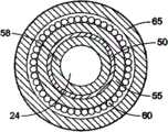
图5-1是修改的中空导电同轴电缆的部分等距截面图,其中介电层置于电缆的内部电导体和外部电导体之间;Figure 5-1 is a partial isometric cross-sectional view of a modified hollow conductive coaxial cable in which the dielectric layer is interposed between the inner and outer electrical conductors of the cable;
图5-2是图5-1所示的修改的中空导电同轴电缆的所选的横截面视图;Figure 5-2 is a selected cross-sectional view of the modified hollow conductive coaxial cable shown in Figure 5-1;
图5-3是中空导电同轴电缆的另一个实施方式的横截面视图,两个分离的介电层置于内部电导体和外部电导体之间;5-3 is a cross-sectional view of another embodiment of a hollow conductive coaxial cable with two separate dielectric layers interposed between an inner electrical conductor and an outer electrical conductor;
图5-4是中空导电同轴电缆的另一可选实施方式的横截面视图,显示了多个介电层置于内部电导体和外部电导体之间;5-4 are cross-sectional views of another alternative embodiment of a hollow conductive coaxial cable showing multiple dielectric layers interposed between inner and outer electrical conductors;
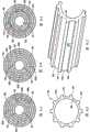
图6-1是中空导电同轴电缆实施方式的另一变体的横截面视图,可选的介电层置于内部电导体和外部电导体之间;Figure 6-1 is a cross-sectional view of another variation of a hollow conductive coaxial cable embodiment with an optional dielectric layer interposed between the inner and outer electrical conductors;
图6-2是图6-1所示的实施方式中的介电材料的横截面视图;Figure 6-2 is a cross-sectional view of the dielectric material in the embodiment shown in Figure 6-1;
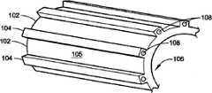
图6-3是图6-1和6-2所示的介电材料的部分等距截面图;Figure 6-3 is a partial isometric cross-sectional view of the dielectric material shown in Figures 6-1 and 6-2;
图7-1是本发明的置于内部电导体和外部电导体之间的介电材料的另一实施方式的横截面视图;7-1 is a cross-sectional view of another embodiment of a dielectric material of the present invention disposed between an inner electrical conductor and an outer electrical conductor;
图7-2是用于图7-1所示的实施方式的介电材料的部分等距截面图;Figure 7-2 is a partial isometric cross-sectional view of the dielectric material used in the embodiment shown in Figure 7-1;
图7-3是本发明的置于内部电导体和外部电导体之间的介电材料的另一可选实施方式的横截面视图;7-3 is a cross-sectional view of another alternative embodiment of a dielectric material of the present invention disposed between an inner electrical conductor and an outer electrical conductor;
图7-4是用于图7-3所示的实施方式的介电材料的部分等距截面图。7-4 is a partial isometric cross-sectional view of the dielectric material used in the embodiment shown in FIG. 7-3.
具体实施方式Detailed ways
本发明提供了新型的射频能量传输装置,该装置合并了中空同轴电缆,该中空同轴电缆传导射频(RF)能量(特别是微波能量),用于消融生物组织。中空电缆具有近端和远端,并且包括同轴的内部导体和外部导体。内部导体包括具有中空的、轴向延伸的腔的细长导电管状元件。外部导体具有被布置为与内部导体基本同轴的细长导电管状元件。电介质可选地置于内部导体和外部导体之间。传递射频能量(特别是微波能量)的消融元件位于电缆的远端部分。中空导电同轴电缆适用于在近端连接RF信号发生器,并且将RF能量(特别是微波能量)传递至安装在远端部分的消融元件。The present invention provides novel radio frequency energy delivery devices incorporating hollow coaxial cables that conduct radio frequency (RF) energy, particularly microwave energy, for ablation of biological tissue. The hollow cable has a proximal end and a distal end, and includes coaxial inner and outer conductors. The inner conductor comprises an elongated conductive tubular member having a hollow, axially extending lumen. The outer conductor has an elongated conductive tubular element arranged substantially coaxially with the inner conductor. A dielectric is optionally interposed between the inner and outer conductors. An ablation element delivering radiofrequency energy, particularly microwave energy, is located at the distal portion of the cable. The hollow conductive coaxial cable is suitable for connecting an RF signal generator at the proximal end and delivering RF energy (in particular microwave energy) to the ablation element mounted at the distal portion.
图1至图3显示了射频能量传输(RF)能量消融系统100,系统100包括:细长的同轴电缆装置20,置于靠近患者的生物组织部位和/或身体血管,或者位于患者的生物组织部位和/或身体血管内;消融装置60,例如RF天线,用于将电磁能传递至治疗部位,更详细的内容如下文所述。1 to 3 show a radio frequency energy delivery (RF) energy ablation system 100, the system 100 includes: an elongated
同轴电缆装置20具有柔性细长的管状体32,管状体32具有近端部分25和远端部分30。位于同轴电缆装置近端部分的是操控(handle)单元40,它包括用于同轴电缆装置的操纵和定位控制(未示出)。RF信号发生器和系统控制单元或系统35通过电缆45连接到同轴电缆装置的近端,并通过同轴电缆电耦合至消融装置60,更详细的内容如下文所述。于2006年6月30日提交的第11/479,259号悬而未决的申请中可能描述了用于对传递到消融装置的RF信号进行控制的RF信号发生器和控制单元,该申请的内容通过引用并入本文。The
在图2至图4中详细地示出了同轴电缆装置20的一个实施方式的结构。同轴电缆装置20的长度和直径要求符合特定的临床操作(medical procedure),这在医疗领域中是众所周知的。同轴装置20是大体管状的并且具有多层结构,中心孔或腔24沿其长度延伸。腔24的远端30可以如图2所示是闭合的,或者在其他的实施方式中可以是打开的,例如,如第6,663,625号美国专利中所描述和显示的,该专利的内容通过引用并入本文。The structure of an embodiment of the
同轴电缆装置20包含第一或内部导电管状元件或导体50,内部导体50具有近端部分和远端部分。内部导体50由具有中空腔24的细长导电管状元件构成。同样由细长导电管状元件制成的外部导体52被设置为与内部导体50的至少一部分长度基本同轴。这种设置在内部导体50的壁与外部导体52的壁之间限定了区域(space)54。
消融装置60位于同轴电缆装置20的远端部分30,并且在接触点62处电耦合至外部同轴导体52,在接触点64处电耦合至内部导体50。然后,内部导体和第二或外部导体电耦合至单元35中的RF能量源。在图示的实施方式中,消融装置60包括螺旋线圈,该螺旋线圈缠绕在同轴电缆装置的外圆周表面上并且从外部导体52的端部延伸至装置20的远端部分或者末端。螺旋线圈60涂覆有介电材料(例如聚合物介电密封材料)的外部涂层65,外部涂层65保护线圈的结构完整性,还保护该线圈使其免受周围生物环境的伤害。在可选的实施方式中,可用其它形式的消融装置或射频天线来取代螺旋线圈60,例如设置在同轴电缆装置远端部分的单极珠天线(monopole bead antenna)、或一对间隔的导电微带(microstrip),如上面所提到的第6,663,625号美国专利中所描述的,该专利的内容通过引用并入本文。RF天线60包含导电材料、或者以螺旋的方式缠绕以形成螺旋线圈的金属条。线圈绕组的适当直径、螺距和长度,以及导电性材料或金属条的选取是选择问题,它可以随现有技术已知的特定工序要求而不同。这里就不再详细描述这些设计要素和注意事项了。
如图1至图3所示,在区域54中提供电介质53以阻止内部导体50和外部导体52之间的电传导。电介质由固体、或流体、或固体和流体的混合物形成。可选地,电介质由介电层55形成,介电层55使内部导体50和外部导体52之间的区域54充分地填充有真空中的未填充区域或者填充可选的介电固体或流体材料。可分配介电流体媒质(例如,空气)来取代固体介电层55。同样表现出介电性质的真空可通过在制造过程中抽走空气和密封电缆的远端部分与近端部分之间的区域54来引入。可选地,真空可通过被构造为与区域54流体流通的真空源来实现,更详细的内容如下文所述。As shown in FIGS. 1-3 , a dielectric 53 is provided in region 54 to prevent electrical conduction between
外护套(jacket)或壳体56沿着同轴电缆装置一直到远端部分30的长度包裹外部导体52。外壳体56通常是由能够与身体血管环境生物相容(bio-compatible)的聚合物材料构造。这种材料的实施例包括具有不同程度的辐射不透性(radiopacity)、硬度和弹性的热塑性弹性体材料,例如来自Autochem Germany的
同轴电缆装置20的管状体可由使用一个或多个上述材料或等同材料的多个节形成,以使得同轴电缆装置20朝向其远端逐渐变得柔性。这些节可通过热粘合、对接或胶接连接在一起。可在管状体的表面设置编织加强层以达到装置期望的硬度和抗扭强度级别,以在患者的身体血管内前进并通过患者的身体血管,同时仍然使远端部分在需要的时候能够弯曲。远端部分30可由比管状体其余部分更软的聚合物复合材料构成,具有很少或没有编织层或加强层,从而为装置的远端弯曲(deflection)和成形提供期望的柔性。The tubular body of the
在一个实施方式中,内部导体50可以用柔性编织线结构或是薄膜导电材料制成。柔性介电材料的内衬或套管(sleeve)58可置于导体50内,以环绕中空的中心孔或腔24。外部导体52可以是编织线结构,或者可以是薄膜导电材料等。套管58、内部导体50和介电层55从操控单元40延伸穿过同轴电缆装置的远端部分,而外部导体52和外壳体56从操控单元40延伸并且在不到装置的远端部分便终止了,外部导体从外部壳体的远端伸出一小段距离,如图2所示。In one embodiment, the
射频天线60适用于接收和发射来自单元35中的射频能量源(未示出)的电磁能量。适当的射频频谱的实施例是从大约300MHz和300MHz以上的微波频率。射频天线60传播由螺旋线圈传输的、基本上均匀分布的电磁场能量。所传输的电磁场功率基本上正交于射频天线的纵向轴线,均匀的能量场关于天线成圈地产生并且由天线界定。被传递用于消融的能量基本上沿着天线均匀地分布,独立于天线与将被消融的组织之间的接触。
图5-1和5-2是本发明的另一个实施方式,合并了一种可选的电介质构造。图5-1和5-2中的类似的标号用于其他附图中的类似部件。在该实施方式中,电介质53由介电层70构成,介电层70置于内部和外部导体之间的区域54内,以环绕内部导体50。在介电层70的纵向外围边缘(peripheral edge)72和74之间提供了间隙76。间隙76沿着同轴电缆的至少一部分长度延伸,并且通常被定向为平行于电缆的轴线,尽管还可以提供其它方向的定位。此外,介电层70的外围边缘72和74可在所选的位置处连结,以沿着内部导体50与外部导体52之间的区域54中的外围边缘的缝隙限定多个空隙。Figures 5-1 and 5-2 are another embodiment of the invention incorporating an alternative dielectric construction. Similar numbers in Figures 5-1 and 5-2 are used for similar components in the other Figures. In this embodiment, the dielectric 53 consists of a
图5-3和5-4显示了中空导电同轴电缆的另外实施方式的横截面视图,在内部和外部电导体之间设置两个或更多分离的介电层。图5-3显示了一种构造,在区域54中设置两片介电层80A,80B。这两个介电层被间隙82A和82B隔开。类似于图5-1和5-2所示的实施方式,间隙82A和82B在与内部导体和外部导体的轴线大体平行的方向、沿着同轴电缆的至少一部分长度延伸,尽管还可提供其他方向的设置。因此,间隙80A和80B在内部和外部导体之间的区域54中、沿着同轴电缆的长度、在介电层之间提供了细长的通道(channel)。Figures 5-3 and 5-4 show cross-sectional views of additional embodiments of hollow conductive coaxial cables with two or more separate dielectric layers disposed between the inner and outer electrical conductors. 5-3 shows a configuration in which two
在图5-4中,在区域54中提供了三片介电层90A、90B、90C。这三片介电层通过间隙92A,92B和92C隔开。类似于图5-1至图5-4所示的实施方式,间隙92A、92B和92C的方向在与内部导体和外部导体的轴线大体平行的方向延伸,尽管还可以提供其他的方向设置。In FIGS. 5-4 , three sheets of
图6-1显示了本发明的又一实施方式,合并了可选的介电材料构造。介电层99设置有一个或多个表面凹部102,并且置于内部导体50和外部导体52之间。在图6-2和6-3的横截面和部分等距截面视图中所示的示例性实施方式中,凹部102形成于细长的脊或高耸的隆起部104之间,脊104沿着与内部导体和外部导体的轴线基本平行的方向延伸。这个实施方式限定了在同轴电缆的远端部分和近端部分之间延伸的至少一个通道。如图6-1,6-2和6-3中所示的实施方式所示,脊104绕着同轴电缆的轴线等角度(equal-angular)排列。脊104可形成为介电层99的一部分。可选地,这些脊可形成为分离的细长条,并且固定在介电层99的表面105上。而且,脊104可假定不同的横截面轮廓,这些横截面轮廓不限于图6-1、6-2、6-3、7-1、7-2、7-3和7-4所示的那些轮廓。Figure 6-1 shows yet another embodiment of the invention incorporating an alternative dielectric material configuration. The
可选地,凹部102可形成和定向为使其相对于内部导体和外部导体的轴线、以脊的方式延伸,从而在内部导体50和外部导体52之间的区域54(未示出)中限定一个或多个脊通道或通路。作为另一可选设计,可在位于内部导体50和外部导体52之间的介电层100的任一侧或两侧(未示出)、以交叉十字方式形成直线(lineal)凹部。此外,代替形成于介电材料表面的锯齿状、直线或以其他方式,凹部可以是穿孔或空隙形式(未示出)。Alternatively, the
图7-1和7-2显示了介电层构造106,至少一个内部通路108选择性地形成于细长脊104中并且沿着脊104的长度延伸,以追随同轴电缆的长度。这种可选的介电构造提供了位于细长脊之间的至少一个开放通道102和在同轴电缆远端部分和近端部分之间延伸的至少一个内部通路108。Figures 7-1 and 7-2 show the
图7-3和7-4显示了本发明的另一实施方式,在内部导体50和外部导体54之间的区域54中构造的可选介电层110在其两个表面上设置有一个或多个表面凹部114。类似于上面所述的实施方式,凹部形成于细长脊112之间,细长脊112在介电层110的内表面116和外表面118上、沿着同轴电缆的纵向方向延伸。该实施方式从同轴电缆的远端部分到近端部分提供了位于同轴电缆的远端部分和近端部分之间的细长内部通道120和外部通道122。7-3 and 7-4 show another embodiment of the present invention, the
在本文所提到的实施方式和通过引用并入本文的参考文献中,内部导体50和外部导体52被构造为基本同轴,导体之间的壁限定了在同轴电缆的长度上延伸的区域54。如上面所讨论的,区域54被构造为插入介电性(dielectricity),用于阻止内部导体和外部导体的电传导,这可能通过引入真空或电介质实现。在电介质方面,它包括置于内部导体50和外部导体52之间的区域之间的固体介电层。可选地,可使用介电流体媒质取代固体介电层。此外,如在上面所举的各种实施方式中那样,在提供间隙和凹部的情况下,可将一个或多个固体介电层和流体(例如空气)置于区域54内。In the embodiments noted herein and in references incorporated herein by reference, the
可选地,一个或多个凹部开口可形成于同轴电缆远端部分和/或近端部分,用于提供区域54与中空腔24之间的连通。如图5-1和5-2所示,远端部分的凹部开口78和近端部分的凹部开口88选择性地形成于内部导体50和内衬58上。这样的特征给消融装置提供了增强的多功能性,以通向内部电缆和外部电缆之间的区域。它还提供附加的装置,以便于引入真空或介电流体,安放装置和仪器,以及将药物(例如,麻醉药、盐水和无菌水)分配给患者用于消融手术。Optionally, one or more recess openings may be formed in the distal and/or proximal portions of the coaxial cable for providing communication between region 54 and
如医疗领域众所周知的,每一个上面实施方式中的同轴电缆装置体部的外直径都要求符合特定的临床操作。在一个实施方式中,这种装置用于消融心肌组织。然而,该装置还可用于消融不同器官中的其他类型的组织,不管是体内还是体外的。同轴电缆装置的管状体可以通常由与身体血管环境生物相容的聚合物材料构成。As is well known in the medical field, the outer diameter of the body of the coaxial cable device in each of the above embodiments is required to conform to a specific clinical practice. In one embodiment, such a device is used to ablate myocardial tissue. However, the device can also be used to ablate other types of tissue in different organs, whether internal or external. The tubular body of the coaxial cable device may generally be constructed of a polymeric material that is biocompatible with the body's vascular environment.
在上面实施方式的每一个中,消融装置或RF天线适用于接收和发射电磁能量,以通过改变所选生物组织部位处的生物组织特性来治疗该部位。例如,用于组织消融的适当的射频频谱的实施例是大于300MHz的微波频率范围。RF天线能够在与天线60的纵向轴线基本垂直的方向,应用沿着RF天线基本均匀分布的电磁场能量。在其近端处连接至RF源和控制单元的细长柔性同轴电缆装置延伸至安装有RF天线的远端部分。每一个上述实施方式中的同轴电缆装置具有从其近端开始延伸且通过电介质隔开的同轴的内部和外部导体,内部导体内的中心腔或孔沿着同轴电缆装置的长度延伸并且可以容纳导线和适当的成形或操纵机构,该导线连接至心电图(ECG)电极、温度传感器等,该成形或操纵机构用于控制同轴电缆装置的、RF天线所在的远端部分的形状或弯曲。In each of the above embodiments, the ablation device or RF antenna is adapted to receive and transmit electromagnetic energy to treat a selected biological tissue site by altering properties of the biological tissue at that site. For example, an example of a suitable radio frequency spectrum for tissue ablation is the microwave frequency range greater than 300 MHz. The RF antenna is capable of applying electromagnetic field energy that is substantially uniformly distributed along the RF antenna in a direction substantially perpendicular to the longitudinal axis of the
提供了对公开的实施方式的上述描述,使本领域的任一技术人员能够制造或使用本发明。各种修改对本领域的技术人员来说是显而易见的,本文中所描述的通用远离可在不背离本发明的精神或范围的前提下应用到其它实施方式中。因而可理解,本文给出的说明书和附图表示本发明目前优选的实施方式,因此可宽泛地预见本发明的代表性主题。进一步理解,本发明的范围完全包含可对本领域的技术人员显而易见的其它实施方式,因此本发明的范围仅由权利要求限定。The above description of the disclosed embodiments is provided to enable any person skilled in the art to make or use the invention. Various modifications will be readily apparent to those skilled in the art, and the general principles described herein may be applied to other embodiments without departing from the spirit or scope of the invention. It is thus to be understood that the specification and drawings given herein represent presently preferred embodiments of the invention and thus broadly envision representative subject matter of the invention. It is further understood that the scope of the present invention fully encompasses other embodiments that may be apparent to those skilled in the art, and that the scope of the present invention is therefore limited only by the claims.
Claims (18)
Applications Claiming Priority (3)
| Application Number | Priority Date | Filing Date | Title |
|---|---|---|---|
| US11/858,736US20090082762A1 (en) | 2007-09-20 | 2007-09-20 | Radio frequency energy transmission device for the ablation of biological tissues |
| US11/858,736 | 2007-09-20 | ||
| PCT/US2008/076523WO2009039093A2 (en) | 2007-09-20 | 2008-09-16 | A radio frequency energy transmission device for the ablation of biological tissues |
Publications (2)
| Publication Number | Publication Date |
|---|---|
| CN101801299A CN101801299A (en) | 2010-08-11 |
| CN101801299Btrue CN101801299B (en) | 2013-06-12 |
Family
ID=40468731
Family Applications (1)
| Application Number | Title | Priority Date | Filing Date |
|---|---|---|---|
| CN200880108127.8AActiveCN101801299B (en) | 2007-09-20 | 2008-09-16 | Radio frequency energy delivery device for ablation of biological tissue |
Country Status (7)
| Country | Link |
|---|---|
| US (1) | US20090082762A1 (en) |
| EP (1) | EP2194902B1 (en) |
| JP (1) | JP5491399B2 (en) |
| KR (1) | KR101552505B1 (en) |
| CN (1) | CN101801299B (en) |
| ES (1) | ES2457821T3 (en) |
| WO (1) | WO2009039093A2 (en) |
Families Citing this family (28)
| Publication number | Priority date | Publication date | Assignee | Title |
|---|---|---|---|---|
| US20070066972A1 (en)* | 2001-11-29 | 2007-03-22 | Medwaves, Inc. | Ablation catheter apparatus with one or more electrodes |
| CN100508910C (en)* | 2001-11-29 | 2009-07-08 | 麦迪威公司 | Radio frequency based catheter system with improved deflection and steering mechanism |
| US8995619B2 (en) | 2010-03-14 | 2015-03-31 | Rapiscan Systems, Inc. | Personnel screening system |
| US8576982B2 (en) | 2008-02-01 | 2013-11-05 | Rapiscan Systems, Inc. | Personnel screening system |
| US8638904B2 (en) | 2010-03-14 | 2014-01-28 | Rapiscan Systems, Inc. | Personnel screening system |
| US9326819B2 (en)* | 2009-04-15 | 2016-05-03 | Medwaves, Inc. | Electrically tunable tissue ablation system and method |
| US8934989B2 (en)* | 2009-04-15 | 2015-01-13 | Medwaves, Inc. | Radio frequency based ablation system and method with dielectric transformer |
| WO2011066445A2 (en) | 2009-11-30 | 2011-06-03 | Medwaves, Inc. | Radio frequency ablation system with tracking sensor |
| US8777939B2 (en)* | 2010-02-26 | 2014-07-15 | Covidien Lp | Self-tuning microwave ablation probe |
| ES2856026T3 (en)* | 2010-05-03 | 2021-09-27 | Neuwave Medical Inc | Power supply systems |
| GB201323171D0 (en)* | 2013-12-31 | 2014-02-12 | Creo Medical Ltd | Electrosurgical apparatus and device |
| US20160361557A1 (en)* | 2014-01-31 | 2016-12-15 | Salvatore Rinaldi | Apparatus and method for repairing and regenerating cardiac tissues and for the electro-physiological, metabolic optimization of the heart |
| US11280898B2 (en) | 2014-03-07 | 2022-03-22 | Rapiscan Systems, Inc. | Radar-based baggage and parcel inspection systems |
| EP3114464A4 (en) | 2014-03-07 | 2017-11-29 | Rapiscan Systems, Inc. | Ultra wide band detectors |
| GB201418486D0 (en)* | 2014-10-17 | 2014-12-03 | Creo Medical Ltd | Cable for conveying radiofrequency and/or microwave frequency energy to an electrosurgical instrument |
| GB201418474D0 (en)* | 2014-10-17 | 2014-12-03 | Creo Medical Ltd | Electrosurgical apparatus |
| JP2016077646A (en)* | 2014-10-17 | 2016-05-16 | 高周波熱錬株式会社 | Organ separation operation tool |
| GB201418479D0 (en)* | 2014-10-17 | 2014-12-03 | Creo Medical Ltd | Cable for conveying radiofrequency and/or microwave frequency energy to an electrosurgical instrument |
| EP3224797A4 (en) | 2014-11-25 | 2018-07-18 | Rapiscan Systems, Inc. | Intelligent security management system |
| GB2545179B (en)* | 2015-12-07 | 2020-09-09 | Creo Medical Ltd | Electrosurgical instrument |
| WO2018140816A1 (en) | 2017-01-26 | 2018-08-02 | Broncus Medical Inc. | Bronchoscopic-based microwave ablation system and method |
| GB2559595B (en) | 2017-02-10 | 2021-09-01 | Creo Medical Ltd | Electrosurgical apparatus and electrosurgical instrument |
| GB2561167A (en)* | 2017-03-30 | 2018-10-10 | Creo Medical Ltd | Electrosurgical energy conveying structure and electrosurgical device incorporating the same |
| GB2576481B (en)* | 2018-05-30 | 2022-07-20 | Creo Medical Ltd | Electrosurgical instrument |
| US11737823B2 (en)* | 2018-10-31 | 2023-08-29 | Intuitive Surgical Operations, Inc. | Antenna systems and methods of use |
| US11571569B2 (en) | 2019-02-15 | 2023-02-07 | Pulse Biosciences, Inc. | High-voltage catheters for sub-microsecond pulsing |
| GB2588070B (en)* | 2019-04-29 | 2022-11-16 | Creo Medical Ltd | Electrosurgical system |
| WO2021026471A2 (en)* | 2019-08-07 | 2021-02-11 | Biocompatibles Uk Limited | Microwave ablation probe |
Family Cites Families (58)
| Publication number | Priority date | Publication date | Assignee | Title |
|---|---|---|---|---|
| US3309455A (en)* | 1964-09-21 | 1967-03-14 | Dow Chemical Co | Coaxial cable with insulating conductor supporting layers bonded to the conductors |
| US4271848A (en)* | 1979-01-11 | 1981-06-09 | Bio Systems Design, Corp. | Apparatus for electromagnetic radiation of living tissue and the like |
| US4408089A (en)* | 1979-11-16 | 1983-10-04 | Nixon Charles E | Extremely low-attenuation, extremely low radiation loss flexible coaxial cable for microwave energy in the gigaHertz frequency range |
| US4674499A (en)* | 1980-12-08 | 1987-06-23 | Pao David S C | Coaxial bipolar probe |
| US4583556A (en)* | 1982-12-13 | 1986-04-22 | M/A-Com, Inc. | Microwave applicator/receiver apparatus |
| US4700716A (en)* | 1986-02-27 | 1987-10-20 | Kasevich Associates, Inc. | Collinear antenna array applicator |
| US5129396A (en)* | 1988-11-10 | 1992-07-14 | Arye Rosen | Microwave aided balloon angioplasty with lumen measurement |
| US4945912A (en)* | 1988-11-25 | 1990-08-07 | Sensor Electronics, Inc. | Catheter with radiofrequency heating applicator |
| JPH05506174A (en)* | 1990-09-14 | 1993-09-16 | アメリカン・メディカル・システムズ・インコーポレーテッド | Combined hyperthermia and dilatation catheter |
| US5413588A (en)* | 1992-03-06 | 1995-05-09 | Urologix, Inc. | Device and method for asymmetrical thermal therapy with helical dipole microwave antenna |
| US5370677A (en)* | 1992-03-06 | 1994-12-06 | Urologix, Inc. | Gamma matched, helical dipole microwave antenna with tubular-shaped capacitor |
| US5275597A (en)* | 1992-05-18 | 1994-01-04 | Baxter International Inc. | Percutaneous transluminal catheter and transmitter therefor |
| WO1994002077A2 (en)* | 1992-07-15 | 1994-02-03 | Angelase, Inc. | Ablation catheter system |
| US5298682A (en)* | 1992-08-20 | 1994-03-29 | Wireworld By David Salz, Inc. | Optimized symmetrical coaxial cable |
| CA2109980A1 (en)* | 1992-12-01 | 1994-06-02 | Mir A. Imran | Steerable catheter with adjustable bend location and/or radius and method |
| US5656796A (en)* | 1993-04-26 | 1997-08-12 | Fmc Corp. | High energy flexible coaxial cable and connections |
| US5405346A (en)* | 1993-05-14 | 1995-04-11 | Fidus Medical Technology Corporation | Tunable microwave ablation catheter |
| US5693082A (en)* | 1993-05-14 | 1997-12-02 | Fidus Medical Technology Corporation | Tunable microwave ablation catheter system and method |
| US5545193A (en)* | 1993-10-15 | 1996-08-13 | Ep Technologies, Inc. | Helically wound radio-frequency emitting electrodes for creating lesions in body tissue |
| US5730127A (en)* | 1993-12-03 | 1998-03-24 | Avitall; Boaz | Mapping and ablation catheter system |
| DE4425195C1 (en)* | 1994-07-16 | 1995-11-16 | Osypka Peter | Heart catheter with multiple electrode device |
| US5885278A (en)* | 1994-10-07 | 1999-03-23 | E.P. Technologies, Inc. | Structures for deploying movable electrode elements |
| US5683382A (en)* | 1995-05-15 | 1997-11-04 | Arrow International Investment Corp. | Microwave antenna catheter |
| US5702433A (en)* | 1995-06-27 | 1997-12-30 | Arrow International Investment Corp. | Kink-resistant steerable catheter assembly for microwave ablation |
| US5788692A (en)* | 1995-06-30 | 1998-08-04 | Fidus Medical Technology Corporation | Mapping ablation catheter |
| US5837001A (en)* | 1995-12-08 | 1998-11-17 | C. R. Bard | Radio frequency energy delivery system for multipolar electrode catheters |
| US5800482A (en)* | 1996-03-06 | 1998-09-01 | Cardiac Pathways Corporation | Apparatus and method for linear lesion ablation |
| US6032077A (en)* | 1996-03-06 | 2000-02-29 | Cardiac Pathways Corporation | Ablation catheter with electrical coupling via foam drenched with a conductive fluid |
| US5863291A (en)* | 1996-04-08 | 1999-01-26 | Cardima, Inc. | Linear ablation assembly |
| US5904709A (en)* | 1996-04-17 | 1999-05-18 | The United States Of America As Represented By The Administrator Of The National Aeronautics And Space Administration | Microwave treatment for cardiac arrhythmias |
| FR2747832B1 (en)* | 1996-04-23 | 1998-05-22 | Filotex Sa | METHOD AND DEVICE FOR MANUFACTURING A VENTILATED SHEATH IN AN INSULATING MATERIAL AROUND A CONDUCTOR, AND COAXIAL CABLE EQUIPPED WITH SUCH SHEATH |
| US5776176A (en)* | 1996-06-17 | 1998-07-07 | Urologix Inc. | Microwave antenna for arterial for arterial microwave applicator |
| US5800494A (en)* | 1996-08-20 | 1998-09-01 | Fidus Medical Technology Corporation | Microwave ablation catheters having antennas with distal fire capabilities |
| US5741249A (en)* | 1996-10-16 | 1998-04-21 | Fidus Medical Technology Corporation | Anchoring tip assembly for microwave ablation catheter |
| US5785706A (en)* | 1996-11-18 | 1998-07-28 | Daig Corporation | Nonsurgical mapping and treatment of cardiac arrhythmia using a catheter contained within a guiding introducer containing openings |
| US5971983A (en)* | 1997-05-09 | 1999-10-26 | The Regents Of The University Of California | Tissue ablation device and method of use |
| US5849028A (en)* | 1997-05-16 | 1998-12-15 | Irvine Biomedical, Inc. | Catheter and method for radiofrequency ablation of cardiac tissue |
| US6014579A (en)* | 1997-07-21 | 2000-01-11 | Cardiac Pathways Corp. | Endocardial mapping catheter with movable electrode |
| US6245062B1 (en)* | 1998-10-23 | 2001-06-12 | Afx, Inc. | Directional reflector shield assembly for a microwave ablation instrument |
| US7070595B2 (en)* | 1998-12-14 | 2006-07-04 | Medwaves, Inc. | Radio-frequency based catheter system and method for ablating biological tissues |
| US20070066972A1 (en)* | 2001-11-29 | 2007-03-22 | Medwaves, Inc. | Ablation catheter apparatus with one or more electrodes |
| US7594913B2 (en)* | 1998-12-14 | 2009-09-29 | Medwaves, Inc. | Radio-frequency based catheter system and method for ablating biological tissues |
| US6190382B1 (en)* | 1998-12-14 | 2001-02-20 | Medwaves, Inc. | Radio-frequency based catheter system for ablation of body tissues |
| US6287302B1 (en)* | 1999-06-14 | 2001-09-11 | Fidus Medical Technology Corporation | End-firing microwave ablation instrument with horn reflection device |
| US6230060B1 (en)* | 1999-10-22 | 2001-05-08 | Daniel D. Mawhinney | Single integrated structural unit for catheter incorporating a microwave antenna |
| US7194297B2 (en)* | 2001-11-13 | 2007-03-20 | Boston Scientific Scimed, Inc. | Impedance-matching apparatus and construction for intravascular device |
| US6706040B2 (en)* | 2001-11-23 | 2004-03-16 | Medlennium Technologies, Inc. | Invasive therapeutic probe |
| CN100508910C (en)* | 2001-11-29 | 2009-07-08 | 麦迪威公司 | Radio frequency based catheter system with improved deflection and steering mechanism |
| GB2403148C2 (en)* | 2003-06-23 | 2013-02-13 | Microsulis Ltd | Radiation applicator |
| US7311703B2 (en)* | 2003-07-18 | 2007-12-25 | Vivant Medical, Inc. | Devices and methods for cooling microwave antennas |
| US7182762B2 (en)* | 2003-12-30 | 2007-02-27 | Smith & Nephew, Inc. | Electrosurgical device |
| US7244254B2 (en)* | 2004-04-29 | 2007-07-17 | Micrablate | Air-core microwave ablation antennas |
| US20070016180A1 (en)* | 2004-04-29 | 2007-01-18 | Lee Fred T Jr | Microwave surgical device |
| US7857810B2 (en)* | 2006-05-16 | 2010-12-28 | St. Jude Medical, Atrial Fibrillation Division, Inc. | Ablation electrode assembly and methods for improved control of temperature and minimization of coagulation and tissue damage |
| GB2434314B (en)* | 2006-01-03 | 2011-06-15 | Microsulis Ltd | Microwave applicator with dipole antenna |
| US20070213703A1 (en)* | 2006-03-13 | 2007-09-13 | Jang Hyun Naam | Electrode for radio frequency tissue ablation |
| US10363092B2 (en)* | 2006-03-24 | 2019-07-30 | Neuwave Medical, Inc. | Transmission line with heat transfer ability |
| US7642451B2 (en)* | 2008-01-23 | 2010-01-05 | Vivant Medical, Inc. | Thermally tuned coaxial cable for microwave antennas |
- 2007
- 2007-09-20USUS11/858,736patent/US20090082762A1/ennot_activeAbandoned
- 2008
- 2008-09-16WOPCT/US2008/076523patent/WO2009039093A2/enactiveApplication Filing
- 2008-09-16JPJP2010525904Apatent/JP5491399B2/enactiveActive
- 2008-09-16ESES08831322.6Tpatent/ES2457821T3/enactiveActive
- 2008-09-16CNCN200880108127.8Apatent/CN101801299B/enactiveActive
- 2008-09-16EPEP08831322.6Apatent/EP2194902B1/enactiveActive
- 2008-09-16KRKR1020107008646Apatent/KR101552505B1/ennot_activeExpired - Fee Related
Also Published As
| Publication number | Publication date |
|---|---|
| JP5491399B2 (en) | 2014-05-14 |
| WO2009039093A2 (en) | 2009-03-26 |
| EP2194902A4 (en) | 2010-09-29 |
| KR20100087111A (en) | 2010-08-03 |
| US20090082762A1 (en) | 2009-03-26 |
| ES2457821T3 (en) | 2014-04-29 |
| EP2194902A2 (en) | 2010-06-16 |
| KR101552505B1 (en) | 2015-09-11 |
| JP2010540029A (en) | 2010-12-24 |
| CN101801299A (en) | 2010-08-11 |
| EP2194902B1 (en) | 2014-01-15 |
| WO2009039093A3 (en) | 2009-05-14 |
Similar Documents
| Publication | Publication Date | Title |
|---|---|---|
| CN101801299B (en) | Radio frequency energy delivery device for ablation of biological tissue | |
| US10299859B2 (en) | Methods and devices for delivering microwave energy | |
| EP2073738B1 (en) | Ablation catheter apparatus with one or more electrodes | |
| CN102711648B (en) | Radiofrequency ablation system with tracking sensor | |
| JP4340320B2 (en) | Hollow coaxial cable device suitable for conducting high-frequency energy and ablating living tissue | |
| EP2478844B1 (en) | Tissue ablation apparatus using ultrasonic imaging | |
| EP2349452B1 (en) | Microwave treatment devices | |
| US6669692B1 (en) | Ablation catheter with cooled linear electrode | |
| US20090093810A1 (en) | Electrophysiology Electrodes and Apparatus Including the Same | |
| EP3600102B1 (en) | An ablation probe | |
| EP1761185A2 (en) | Cell necrosis apparatus with cooled microwave antenna | |
| US11219484B2 (en) | Methods and devices for delivering microwave energy | |
| CN112638300A (en) | Ablation lesion device |
Legal Events
| Date | Code | Title | Description |
|---|---|---|---|
| C06 | Publication | ||
| PB01 | Publication | ||
| C10 | Entry into substantive examination | ||
| SE01 | Entry into force of request for substantive examination | ||
| C14 | Grant of patent or utility model | ||
| GR01 | Patent grant |