CN101799672A - Control circuit for realizing single-line transmission among multiple devices - Google Patents
Control circuit for realizing single-line transmission among multiple devicesDownload PDFInfo
- Publication number
- CN101799672A CN101799672ACN201010133602ACN201010133602ACN101799672ACN 101799672 ACN101799672 ACN 101799672ACN 201010133602 ACN201010133602 ACN 201010133602ACN 201010133602 ACN201010133602 ACN 201010133602ACN 101799672 ACN101799672 ACN 101799672A
- Authority
- CN
- China
- Prior art keywords
- control
- resistance
- control circuit
- line
- unit
- Prior art date
- Legal status (The legal status is an assumption and is not a legal conclusion. Google has not performed a legal analysis and makes no representation as to the accuracy of the status listed.)
- Granted
Links
Images
Landscapes
- Cable Transmission Systems, Equalization Of Radio And Reduction Of Echo (AREA)
Abstract
Translated fromChinese
Description
Translated fromChinese技术领域technical field
本发明涉及电器控制领域,尤其是一种实现多设备间单线传输的控制电路。The invention relates to the field of electric appliance control, in particular to a control circuit for realizing single-wire transmission between multiple devices.
背景技术Background technique
在一个单片机对多个设备进行控制时,比如在机器人的控制中,由于涉及众多的舵机控制,每个舵机都需要3根导线:电源线、地线以及信号线与单片机进行连接。假设整个系统中有5个舵机,5个舵机就需要7根导线与单片机进行连接,其中,7根导线中包括1根电源线、1根地线和5根信号线。在单片机单独控制各个舵机的情况下,由于舵机众多,因而需要耗费大量的导线,扩大了导线所占用的空间,导致安装和维修不便,同时,大量的导线增加了系统的故障点,使整个系统的抗干扰能力和可靠性降低。此外,大量的导线同时也增加了机器人的体积、重量和生产成本。When a single-chip microcomputer controls multiple devices, such as in the control of a robot, due to the control of many steering gears, each steering gear needs 3 wires: the power line, the ground wire and the signal line are connected to the single-chip microcomputer. Assuming that there are 5 steering gears in the whole system, 5 steering gears need 7 wires to connect with the microcontroller, among which, 7 wires include 1 power wire, 1 ground wire and 5 signal wires. In the case where the single chip microcomputer controls each steering gear individually, due to the large number of steering gears, a large number of wires are required, which expands the space occupied by the wires, resulting in inconvenient installation and maintenance. At the same time, a large number of wires increase the system. The anti-interference ability and reliability of the whole system are reduced. In addition, a large number of wires also increases the volume, weight and production cost of the robot.
发明内容Contents of the invention
本发明的目的在于提供一种仅通过一根信号线即可实现一个主控单元与多个被控单元之间信号传输的实现多设备间单线传输的控制电路,这种控制电路的可靠性高、抗干扰能力强。The purpose of the present invention is to provide a control circuit for single-line transmission between multiple devices that can realize signal transmission between a master control unit and multiple controlled units through only one signal line, and the reliability of this control circuit is high , Strong anti-interference ability.
为实现上述目的,本发明采用了以下技术方案:一种实现多设备间单线传输的控制电路,包括一个主控单元和多个被控单元,主控单元与各被控单元之间通过一根PWM信号控制线相连接,主控单元输出幅度、频率可调的PWM脉冲控制信号至各被控单元。In order to achieve the above object, the present invention adopts the following technical solutions: a control circuit for realizing single-wire transmission between multiple devices, including a master control unit and multiple controlled units, the master control unit and each controlled unit are connected by a The PWM signal control lines are connected to each other, and the main control unit outputs PWM pulse control signals with adjustable amplitude and frequency to each controlled unit.
由上述技术方案可知,本发明完全改变了传统的多线控制方式,实现了对控制系统中多个电器单元的单线控制,由于控制线束的减少,使系统故障点降低,使整个控制装置的抗干扰能力及可靠性大大提高。同时,由于节省了导线材料和其所占用的空间,便于系统布置控制电路,最终也降低了经济成本。It can be seen from the above technical solution that the present invention has completely changed the traditional multi-line control mode, and realized the single-line control of multiple electrical units in the control system. Due to the reduction of the control wire harness, the failure points of the system are reduced, and the resistance of the entire control device is reduced. Interference ability and reliability are greatly improved. At the same time, because the wire material and the space occupied by it are saved, it is convenient to arrange the control circuit in the system, and finally the economic cost is also reduced.
附图说明Description of drawings
图1是本发明的结构框图;Fig. 1 is a block diagram of the present invention;
图2是本发明中主控单元的电路图;Fig. 2 is the circuit diagram of main control unit among the present invention;
图3是本发明中被控单元的电路图。Fig. 3 is a circuit diagram of the controlled unit in the present invention.
具体实施方式Detailed ways
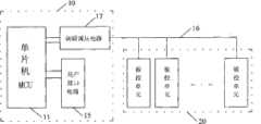
一种实现多设备间单线传输的控制电路,包括一个主控单元10和多个被控单元20,所述的被控单元20的个数为两个或两个以上。主控单元10与各被控单元20之间通过一根PWM信号控制线16相连接,主控单元10输出幅度、频率可调的PWM脉冲控制信号至各被控单元20。如图1所示。A control circuit for realizing single-wire transmission between multiple devices includes a
结合图2,所述的主控单元10包括单片机MCU 11,单片机MCU 11的输出端与调频调压电路17的输入端相连,调频调压电路17的输出端通过一根PWM信号控制线16与各个被控单元20的输入端连接。所述的单片机MCU 11的输入端与用于可供用户操作的用户接口电路15的输出端相连。用户接口电路15用于实现用户通过单片机MCU 11对各个被控单元20的操作和控制。In conjunction with Fig. 2, described
结合图2,所述的调频调压电路17包括电源芯片LM317 12,电源芯片LM317 12的输入引脚接14V直流电,电源芯片LM317 12的输出引脚接单刀双掷开关MAX4544 14的公共端COM,电源芯片LM317 12的电压调节引脚与输出引脚之间接电阻R1,电源芯片LM317 12的电压调节引脚与数字电位器13的一端相连,数字电位器13的另一端通过I2C协议与单片机MCU 11通讯,实现输出电压的软件可编程控制,I2C协议为主、从机之间的通讯协议,电源芯片LM317 12的输入、输出引脚对地接滤波电容。电源芯片LM317 12的输出电压为VCC1,该输出电压VCC1是由数字电位器13调节的可变电压。In conjunction with Fig. 2, the frequency modulation and
结合图2,所述的调频调压电路17还包括单刀双掷开关MAX4544 14,单刀双掷开关MAX4544 14的控制电平输入端接单片机MCU 11的PWM信号输出端相连,单片机MCU 11通过I/O引脚输出频率可变的PWM脉冲信号,供单刀双掷开关MAX4544 14作为开关的关断频率,该PWM脉冲信号是由设置在单片机MCU 11内部的PWM寄存器发出或者通过软件编程实现的。单刀双掷开关MAX4544 14常闭触头NC的引出线分三路输出,一路作为与各被控单元20连接的PWM信号控制线16,一路通过电阻R4接电源芯片LM317 12的输出引脚,一路与电阻R3的一端相连,电阻R3与电阻R2串联,电阻R2的另一端接地,单刀双掷开关MAX4544 14常开触头NO的引出线接在电阻R2和电阻R3之间。电阻R2、R3、R4的阻值可以根据需要设定。当PWM脉冲信号输出高电平时,单刀双掷开关MAX4544 14的公共端COM与常闭触头NC连接,此时A点的输出电压为VCC1;反之,当PWM脉冲信号输出低电平时,单刀双掷开关MAX4544 14的公共端COM与常开触头NO连接,此时A点的输出电压为(R3+R4)/R3×VCC1,可见,调节VCC1就可以调节输出的脉冲的电压值。In conjunction with Fig. 2, described frequency modulation and
结合图3,所述的被控单元20包括双门限比较器21,双门限比较器21的电压输入端与调频调压电路17的输出端相连,双门限比较器21的输出端与执行装置22的输入端相连,双门限比较器21的门限电压范围落在PWM脉冲控制信号的幅值范围内。各个被控单元20的双门限比较器21的门限电压范围各异,以确保在其自身的门限电压区间内的PWM脉冲控制信号为该被控单元20所识别,并通过双门限比较器21输出高电平从而控制执行机构,达到控制的目的。3, the controlled
综上所述,本发明的核心在于通过主控单元10调节出不同的参考电压VCC1,就可以完成单线对各被控单元20的工作状态的控制,且各被控单元20的控制相互独立、互不干涉,从而可靠的完成各种控制工作,由于只用一根PWM信号控制线16进行传输控制,大大的减少了线束接点的数量,降低了系统布线的难度,此系统的体积和重量及成本方面都有显著改善。To sum up, the core of the present invention is that the
Claims (7)
Priority Applications (1)
| Application Number | Priority Date | Filing Date | Title |
|---|---|---|---|
| CN201010133602.6ACN101799672B (en) | 2010-03-24 | 2010-03-24 | Control circuit for realizing single-line transmission among multiple devices |
Applications Claiming Priority (1)
| Application Number | Priority Date | Filing Date | Title |
|---|---|---|---|
| CN201010133602.6ACN101799672B (en) | 2010-03-24 | 2010-03-24 | Control circuit for realizing single-line transmission among multiple devices |
Publications (2)
| Publication Number | Publication Date |
|---|---|
| CN101799672Atrue CN101799672A (en) | 2010-08-11 |
| CN101799672B CN101799672B (en) | 2015-04-08 |
Family
ID=42595379
Family Applications (1)
| Application Number | Title | Priority Date | Filing Date |
|---|---|---|---|
| CN201010133602.6AActiveCN101799672B (en) | 2010-03-24 | 2010-03-24 | Control circuit for realizing single-line transmission among multiple devices |
Country Status (1)
| Country | Link |
|---|---|
| CN (1) | CN101799672B (en) |
Cited By (1)
| Publication number | Priority date | Publication date | Assignee | Title |
|---|---|---|---|---|
| CN106603111A (en)* | 2016-11-14 | 2017-04-26 | 成都合立微波技术有限公司 | Frequency-agility signal generator |
Citations (4)
| Publication number | Priority date | Publication date | Assignee | Title |
|---|---|---|---|---|
| EP0692753A2 (en)* | 1994-07-12 | 1996-01-17 | RKC Instruments Inc. | Control device |
| US20050269580A1 (en)* | 2004-06-04 | 2005-12-08 | D Angelo Kevin P | Single wire serial protocol for RGB LED drivers |
| CN201281810Y (en)* | 2008-09-26 | 2009-07-29 | 耿乐 | Automatic control device |
| CN201315685Y (en)* | 2008-10-31 | 2009-09-23 | 上海欧切斯实业有限公司 | DMX512 master controller |
- 2010
- 2010-03-24CNCN201010133602.6Apatent/CN101799672B/enactiveActive
Patent Citations (4)
| Publication number | Priority date | Publication date | Assignee | Title |
|---|---|---|---|---|
| EP0692753A2 (en)* | 1994-07-12 | 1996-01-17 | RKC Instruments Inc. | Control device |
| US20050269580A1 (en)* | 2004-06-04 | 2005-12-08 | D Angelo Kevin P | Single wire serial protocol for RGB LED drivers |
| CN201281810Y (en)* | 2008-09-26 | 2009-07-29 | 耿乐 | Automatic control device |
| CN201315685Y (en)* | 2008-10-31 | 2009-09-23 | 上海欧切斯实业有限公司 | DMX512 master controller |
Non-Patent Citations (1)
| Title |
|---|
| 张立勋等: "基于ATmega128和FPGA的六自由度机器人的直流伺服控制器设计", 《电子器件》* |
Cited By (1)
| Publication number | Priority date | Publication date | Assignee | Title |
|---|---|---|---|---|
| CN106603111A (en)* | 2016-11-14 | 2017-04-26 | 成都合立微波技术有限公司 | Frequency-agility signal generator |
Also Published As
| Publication number | Publication date |
|---|---|
| CN101799672B (en) | 2015-04-08 |
Similar Documents
| Publication | Publication Date | Title |
|---|---|---|
| CN109269033B (en) | Centralized control converter and air conditioning system | |
| CN114844491B (en) | Single live wire intelligent switch and single live wire multi-control switch | |
| CN108605018A (en) | The circuit device of changeable line terminal for universal serial bus | |
| CN103676729B (en) | Digital knob switch multiplexing device and adopt the electronics of described device | |
| CN204679795U (en) | Sensor signal conversion equipment | |
| CA2939640A1 (en) | Multifunctional ecm and hvac system using same | |
| CN112202571A (en) | A POE power transmission device, POE switch and POE system | |
| CN206962725U (en) | It is a kind of can the shared novel inverter of single three-phase | |
| CN109287056A (en) | A single live wire electronic switch | |
| CN209232137U (en) | A Multi-Channel High-precision Parallel Signal Acquisition Digital Transmitter | |
| CN101799672B (en) | Control circuit for realizing single-line transmission among multiple devices | |
| CN105629823A (en) | Extensible modular small-sized controller device | |
| CN110758151A (en) | A kind of electronic equipment and hardware address configuration method | |
| CN208722000U (en) | Communication circuit and cooking utensil | |
| CN103701439B (en) | A kind of single-input dual-output pulse-width modulation signal generating circuit | |
| CN109739801A (en) | A kind of serial port level chance-over circuit between MCU chip and SOC chip | |
| CN204442329U (en) | A kind of mechanical switch remote-control module and intelligent switch | |
| CN204406110U (en) | Multiplexing interface device, apparatus, and system using the multiplexing interface device | |
| CN107562165B (en) | A power supply device and power management system for supplying power to a server | |
| CN203206567U (en) | LED lamp adjustment and control system | |
| CN215416317U (en) | An electrical control circuit and oven | |
| US10375796B2 (en) | Waveform shaping circuit for spurious harmonic suppression | |
| CN216697035U (en) | Switch control module, signal transmission device and control system | |
| KR20150003380U (en) | Smart switch | |
| CN114647205A (en) | Universal data acquisition device and method |
Legal Events
| Date | Code | Title | Description |
|---|---|---|---|
| C06 | Publication | ||
| PB01 | Publication | ||
| C10 | Entry into substantive examination | ||
| SE01 | Entry into force of request for substantive examination | ||
| C14 | Grant of patent or utility model | ||
| GR01 | Patent grant | ||
| OL01 | Intention to license declared | ||
| OL01 | Intention to license declared |