CN101795646A - System and method for bilateral simultaneous treatment of target tissue in the ear - Google Patents
System and method for bilateral simultaneous treatment of target tissue in the earDownload PDFInfo
- Publication number
- CN101795646A CN101795646ACN200880020861ACN200880020861ACN101795646ACN 101795646 ACN101795646 ACN 101795646ACN 200880020861 ACN200880020861 ACN 200880020861ACN 200880020861 ACN200880020861 ACN 200880020861ACN 101795646 ACN101795646 ACN 101795646A
- Authority
- CN
- China
- Prior art keywords
- ear
- equipment
- electrode
- patient
- ionotherapy
- Prior art date
- Legal status (The legal status is an assumption and is not a legal conclusion. Google has not performed a legal analysis and makes no representation as to the accuracy of the status listed.)
- Granted
Links
Images


Classifications
- A—HUMAN NECESSITIES
- A61—MEDICAL OR VETERINARY SCIENCE; HYGIENE
- A61M—DEVICES FOR INTRODUCING MEDIA INTO, OR ONTO, THE BODY; DEVICES FOR TRANSDUCING BODY MEDIA OR FOR TAKING MEDIA FROM THE BODY; DEVICES FOR PRODUCING OR ENDING SLEEP OR STUPOR
- A61M31/00—Devices for introducing or retaining media, e.g. remedies, in cavities of the body
- A—HUMAN NECESSITIES
- A61—MEDICAL OR VETERINARY SCIENCE; HYGIENE
- A61B—DIAGNOSIS; SURGERY; IDENTIFICATION
- A61B1/00—Instruments for performing medical examinations of the interior of cavities or tubes of the body by visual or photographical inspection, e.g. endoscopes; Illuminating arrangements therefor
- A61B1/00064—Constructional details of the endoscope body
- A61B1/00071—Insertion part of the endoscope body
- A61B1/0008—Insertion part of the endoscope body characterised by distal tip features
- A61B1/00082—Balloons
- A—HUMAN NECESSITIES
- A61—MEDICAL OR VETERINARY SCIENCE; HYGIENE
- A61B—DIAGNOSIS; SURGERY; IDENTIFICATION
- A61B1/00—Instruments for performing medical examinations of the interior of cavities or tubes of the body by visual or photographical inspection, e.g. endoscopes; Illuminating arrangements therefor
- A61B1/227—Instruments for performing medical examinations of the interior of cavities or tubes of the body by visual or photographical inspection, e.g. endoscopes; Illuminating arrangements therefor for ears, i.e. otoscopes
- A—HUMAN NECESSITIES
- A61—MEDICAL OR VETERINARY SCIENCE; HYGIENE
- A61B—DIAGNOSIS; SURGERY; IDENTIFICATION
- A61B5/00—Measuring for diagnostic purposes; Identification of persons
- A61B5/0059—Measuring for diagnostic purposes; Identification of persons using light, e.g. diagnosis by transillumination, diascopy, fluorescence
- A61B5/0077—Devices for viewing the surface of the body, e.g. camera, magnifying lens
- A—HUMAN NECESSITIES
- A61—MEDICAL OR VETERINARY SCIENCE; HYGIENE
- A61F—FILTERS IMPLANTABLE INTO BLOOD VESSELS; PROSTHESES; DEVICES PROVIDING PATENCY TO, OR PREVENTING COLLAPSING OF, TUBULAR STRUCTURES OF THE BODY, e.g. STENTS; ORTHOPAEDIC, NURSING OR CONTRACEPTIVE DEVICES; FOMENTATION; TREATMENT OR PROTECTION OF EYES OR EARS; BANDAGES, DRESSINGS OR ABSORBENT PADS; FIRST-AID KITS
- A61F11/00—Methods or devices for treatment of the ears or hearing sense; Non-electric hearing aids; Methods or devices for enabling ear patients to achieve auditory perception through physiological senses other than hearing sense; Protective devices for the ears, carried on the body or in the hand
- A61F11/20—Ear surgery
- A61F11/202—Surgical middle-ear ventilation or drainage, e.g. permanent; Implants therefor
- A—HUMAN NECESSITIES
- A61—MEDICAL OR VETERINARY SCIENCE; HYGIENE
- A61N—ELECTROTHERAPY; MAGNETOTHERAPY; RADIATION THERAPY; ULTRASOUND THERAPY
- A61N1/00—Electrotherapy; Circuits therefor
- A61N1/18—Applying electric currents by contact electrodes
- A61N1/20—Applying electric currents by contact electrodes continuous direct currents
- A61N1/30—Apparatus for iontophoresis, i.e. transfer of media in ionic state by an electromotoric force into the body, or cataphoresis
- A61N1/303—Constructional details
- A61N1/306—Arrangements where at least part of the apparatus is introduced into the body
- A—HUMAN NECESSITIES
- A61—MEDICAL OR VETERINARY SCIENCE; HYGIENE
- A61B—DIAGNOSIS; SURGERY; IDENTIFICATION
- A61B17/00—Surgical instruments, devices or methods
- A61B2017/00743—Type of operation; Specification of treatment sites
- A61B2017/00787—Surgery of the ear
- A—HUMAN NECESSITIES
- A61—MEDICAL OR VETERINARY SCIENCE; HYGIENE
- A61F—FILTERS IMPLANTABLE INTO BLOOD VESSELS; PROSTHESES; DEVICES PROVIDING PATENCY TO, OR PREVENTING COLLAPSING OF, TUBULAR STRUCTURES OF THE BODY, e.g. STENTS; ORTHOPAEDIC, NURSING OR CONTRACEPTIVE DEVICES; FOMENTATION; TREATMENT OR PROTECTION OF EYES OR EARS; BANDAGES, DRESSINGS OR ABSORBENT PADS; FIRST-AID KITS
- A61F2230/00—Geometry of prostheses classified in groups A61F2/00 - A61F2/26 or A61F2/82 or A61F9/00 or A61F11/00 or subgroups thereof
- A61F2230/0002—Two-dimensional shapes, e.g. cross-sections
- A61F2230/0028—Shapes in the form of latin or greek characters
- A61F2230/0039—H-shaped
- A—HUMAN NECESSITIES
- A61—MEDICAL OR VETERINARY SCIENCE; HYGIENE
- A61F—FILTERS IMPLANTABLE INTO BLOOD VESSELS; PROSTHESES; DEVICES PROVIDING PATENCY TO, OR PREVENTING COLLAPSING OF, TUBULAR STRUCTURES OF THE BODY, e.g. STENTS; ORTHOPAEDIC, NURSING OR CONTRACEPTIVE DEVICES; FOMENTATION; TREATMENT OR PROTECTION OF EYES OR EARS; BANDAGES, DRESSINGS OR ABSORBENT PADS; FIRST-AID KITS
- A61F2230/00—Geometry of prostheses classified in groups A61F2/00 - A61F2/26 or A61F2/82 or A61F9/00 or A61F11/00 or subgroups thereof
- A61F2230/0002—Two-dimensional shapes, e.g. cross-sections
- A61F2230/0028—Shapes in the form of latin or greek characters
- A61F2230/0052—T-shaped
- A—HUMAN NECESSITIES
- A61—MEDICAL OR VETERINARY SCIENCE; HYGIENE
- A61F—FILTERS IMPLANTABLE INTO BLOOD VESSELS; PROSTHESES; DEVICES PROVIDING PATENCY TO, OR PREVENTING COLLAPSING OF, TUBULAR STRUCTURES OF THE BODY, e.g. STENTS; ORTHOPAEDIC, NURSING OR CONTRACEPTIVE DEVICES; FOMENTATION; TREATMENT OR PROTECTION OF EYES OR EARS; BANDAGES, DRESSINGS OR ABSORBENT PADS; FIRST-AID KITS
- A61F2250/00—Special features of prostheses classified in groups A61F2/00 - A61F2/26 or A61F2/82 or A61F9/00 or A61F11/00 or subgroups thereof
- A61F2250/0014—Special features of prostheses classified in groups A61F2/00 - A61F2/26 or A61F2/82 or A61F9/00 or A61F11/00 or subgroups thereof having different values of a given property or geometrical feature, e.g. mechanical property or material property, at different locations within the same prosthesis
- A61F2250/0039—Special features of prostheses classified in groups A61F2/00 - A61F2/26 or A61F2/82 or A61F9/00 or A61F11/00 or subgroups thereof having different values of a given property or geometrical feature, e.g. mechanical property or material property, at different locations within the same prosthesis differing in diameter
- A—HUMAN NECESSITIES
- A61—MEDICAL OR VETERINARY SCIENCE; HYGIENE
- A61F—FILTERS IMPLANTABLE INTO BLOOD VESSELS; PROSTHESES; DEVICES PROVIDING PATENCY TO, OR PREVENTING COLLAPSING OF, TUBULAR STRUCTURES OF THE BODY, e.g. STENTS; ORTHOPAEDIC, NURSING OR CONTRACEPTIVE DEVICES; FOMENTATION; TREATMENT OR PROTECTION OF EYES OR EARS; BANDAGES, DRESSINGS OR ABSORBENT PADS; FIRST-AID KITS
- A61F2250/00—Special features of prostheses classified in groups A61F2/00 - A61F2/26 or A61F2/82 or A61F9/00 or A61F11/00 or subgroups thereof
- A61F2250/0058—Additional features; Implant or prostheses properties not otherwise provided for
- A61F2250/0082—Additional features; Implant or prostheses properties not otherwise provided for specially designed for children, e.g. having means for adjusting to their growth
- A—HUMAN NECESSITIES
- A61—MEDICAL OR VETERINARY SCIENCE; HYGIENE
- A61M—DEVICES FOR INTRODUCING MEDIA INTO, OR ONTO, THE BODY; DEVICES FOR TRANSDUCING BODY MEDIA OR FOR TAKING MEDIA FROM THE BODY; DEVICES FOR PRODUCING OR ENDING SLEEP OR STUPOR
- A61M2210/00—Anatomical parts of the body
- A61M2210/06—Head
- A61M2210/0662—Ears
Landscapes
- Health & Medical Sciences (AREA)
- Life Sciences & Earth Sciences (AREA)
- Biomedical Technology (AREA)
- Engineering & Computer Science (AREA)
- Public Health (AREA)
- Veterinary Medicine (AREA)
- Animal Behavior & Ethology (AREA)
- General Health & Medical Sciences (AREA)
- Heart & Thoracic Surgery (AREA)
- Surgery (AREA)
- Radiology & Medical Imaging (AREA)
- Nuclear Medicine, Radiotherapy & Molecular Imaging (AREA)
- Physics & Mathematics (AREA)
- Biophysics (AREA)
- Molecular Biology (AREA)
- Medical Informatics (AREA)
- Pathology (AREA)
- Hematology (AREA)
- Anesthesiology (AREA)
- Acoustics & Sound (AREA)
- Otolaryngology (AREA)
- Vascular Medicine (AREA)
- Optics & Photonics (AREA)
- Psychology (AREA)
- Media Introduction/Drainage Providing Device (AREA)
- Infusion, Injection, And Reservoir Apparatuses (AREA)
- Measurement Of The Respiration, Hearing Ability, Form, And Blood Characteristics Of Living Organisms (AREA)
- Electrotherapy Devices (AREA)
- Measuring And Recording Apparatus For Diagnosis (AREA)
- External Artificial Organs (AREA)
Abstract
Translated fromChinese
Description
Translated fromChinese相关申请的交叉引用Cross References to Related Applications
本申请要求享有于2007年4月19日提交的美国临时专利申请No.60/912,902的优先权,该临时申请的示教在此通过引用并入本文。This application claims priority to US Provisional Patent Application No. 60/912,902, filed April 19, 2007, the teachings of which are hereby incorporated by reference.
发明背景Background of the invention
本发明一般涉及医疗设备和装置。具体地,本发明提供用于治疗患者的耳的系统、方法、设备以及成套工具。在一个实施方式中,本发明提供用于在放置或不放置鼓膜造孔管(tympanostomy tube)时进行鼓膜穿刺术、鼓膜造孔术或鼓膜切开术的系统和方法,以及用于要求操作或穿透鼓膜的其它手术比如鼓膜穿刺术的系统和方法。The present invention relates generally to medical equipment and devices. Specifically, the present invention provides systems, methods, devices, and kits for treating a patient's ear. In one embodiment, the present invention provides systems and methods for performing tympanocentesis, tympanostomy, or myringotomy with or without placement of a tympanostomy tube, as well as methods for requiring procedures or Systems and methods for other procedures to penetrate the eardrum, such as myringocentesis.
在儿科医生做出的诊断中最为常见的诊断有中耳炎。大多数儿童在他们三岁之前可能患有至少一段时间的中耳炎(“耳痛”)。中耳炎通常由咽鼓管不能排出来自中耳的流体引起。中耳炎经常使用抗生素来治疗。The most common diagnosis made by pediatricians is otitis media. Most children will likely suffer from otitis media ("ear pain") for at least some time before they are three years old. Otitis media is usually caused by the failure of the Eustachian tube to drain fluid from the middle ear. Otitis media is often treated with antibiotics.
大量的儿童表现出反复发作的中耳炎和/或带有渗出物的中耳炎。对这些更加严重的病例的治疗经常涉及穿过鼓膜放置鼓膜造孔管,以便为中耳提供充分的引流并降低将来感染的可能性。鼓膜造孔管在中耳和外耳之间提供流体相通,并且一般地在放置后的大约1年内自发地掉落出去。放置鼓膜造孔管是在儿科群体中实施的最常见的外科手术之一。据估计,每年可能有多于100万的鼓膜造孔管被放置,其中实施手术时患者的年龄一般在大约18个月到7岁之间。A large number of children present with recurrent otitis media and/or otitis media with effusion. Treatment for these more severe cases often involves placement of a tympanostomy tube through the eardrum to provide adequate drainage to the middle ear and reduce the likelihood of future infections. The tympanostomy tube provides fluid communication between the middle ear and the outer ear, and typically falls out spontaneously within about 1 year of placement. Placement of a tympanostomy tube is one of the most common surgical procedures performed in the pediatric population. It is estimated that more than 1 million tympanostomy tubes may be placed each year, with patients typically between about 18 months and 7 years of age at the time of the procedure.
放置鼓膜造孔管一般地在门诊手术环境中在全身麻醉下实施。通过手持式圆锥形窥镜(hand-held conical shaped speculum)在显微目测下对外耳道和鼓膜进行检查。一般地使用细长的、轮廓小的手术刀在鼓膜中进行切开或鼓膜切开术,医生将手术刀延伸穿过圆锥形窥镜。可以通过鼓膜切开术吸出流体,并且放置鼓膜造孔管以便延伸穿过鼓膜。Placement of a tympanostomy tube is generally performed under general anesthesia in an outpatient surgical setting. The external auditory canal and tympanic membrane are examined under microscopic inspection with a hand-held conical shaped speculum. An incision, or myringotomy, is typically made in the eardrum using a thin, low-profile scalpel that the physician extends through a conical speculum. Fluid may be aspirated through a myringotomy and a tympanostomy tube placed to extend through the eardrum.
商业上可以买到多种多样的鼓膜造孔管,并且仍然提出了更多的其它管。已经提出了很多系统来实施鼓膜切开术并使用单次治疗组件(treatment assembly)来部署鼓膜造孔管。在近些年中,已经为耳组织的诊断或治疗提出了更复杂且更昂贵的系统,包括使用激光来形成鼓膜切开术的系统、用于使耳道成像的视频系统以及类似系统。这些各种可选形式已经毫无意外地获得了不同程度的认可。A wide variety of tympanostomy tubes are commercially available, and still many more have been proposed. A number of systems have been proposed to perform a myringotomy and deploy a tympanostomy tube using a single treatment assembly. In recent years, more complex and expensive systems have been proposed for the diagnosis or treatment of ear tissue, including systems using lasers to create a myringotomy, video systems for imaging the ear canal, and the like. These various alternatives have, not surprisingly, gained varying degrees of acceptance.
标准的放置鼓膜造孔管手术是既有效又很安全的。尽管如此,进一步的改进将是理想的。具体地,关于在全身麻醉下实施的门诊外科手术既有风险又有成本。例如,放置鼓膜造孔管的风险和成本的重要部分和全身麻醉的实施有关,即,需要手术室、麻醉学医师的出席以及相关的恢复室时间。Standard tympanostomy tube placement is both effective and safe. Still, further improvements would be ideal. In particular, there are risks and costs associated with outpatient surgical procedures performed under general anesthesia. For example, a significant portion of the risks and costs of placing a tympanostomy tube is related to the administration of general anesthesia, ie, the need for the operating room, the presence of an anesthesiologist, and the associated recovery room time.
按照上文,为耳道内的组织结构的治疗提供改进的设备、系统、方法以及成套工具将是理想的。一般,如果这些改进有利于在放置或不放置鼓膜造孔管时进行鼓膜切开术而无须诉诸于全身麻醉,从而允许这些普通手术在医师办公室中(而不是在门诊手术设施中)实施则将是有益的。有一些研究暗示,将儿童置于全身麻醉之下可能在发育中的脑中诱发神经元退化。因此,提供用于在不使用全身麻醉时对耳道内的组织结构进行治疗的设备、系统、方法以及成套工具将是理想的。如果提供这些改进的同时降低了总的手术时间,以及理想地,降低了总的手术成本则将是更理想的。In light of the above, it would be desirable to provide improved devices, systems, methods and kits for the treatment of tissue structures within the ear canal. In general, if these improvements facilitate myringotomy with or without placement of a tympanostomy tube without resorting to general anesthesia, allowing these common procedures to be performed in a physician's office rather than in an outpatient surgical facility then would be helpful. There are some studies suggesting that placing children under general anesthesia may induce neuronal degeneration in the developing brain. Accordingly, it would be desirable to provide devices, systems, methods and kits for treating tissue structures within the ear canal without the use of general anesthesia. It would be more desirable if these improvements were provided while reducing the overall procedure time, and ideally, the overall procedure cost.
发明简述Brief description of the invention
本发明提供用于在患者清醒且可移动的基于办公室的手术中对遭受复发性耳炎或具有渗出物的中耳炎的儿童的耳的目标组织提供无痛、同步、两侧治疗的系统和方法,其建立成能够控制儿童的焦虑。The present invention provides systems and methods for providing painless, simultaneous, bilateral treatment of target tissue in the ear of children suffering from recurrent otitis or otitis media with exudates in an office-based procedure where the patient is awake and mobile , which was established to control anxiety in children.
在一方面,本发明提供用于患者头部的第一耳和第二耳的两侧治疗的系统和方法,该系统和方法通过将第一设备与第一耳的目标组织对准;将第二设备与第二耳的目标组织对准;以及分别使用对准的第一设备和对准的第二设备同步治疗性地重塑第一耳和第二耳的目标组织来运行。In one aspect, the present invention provides systems and methods for bilateral treatment of first and second ears of a patient's head by aligning a first device with target tissue of the first ear; aligning two devices with target tissue of the second ear; and synchronously therapeutically remodeling target tissue of the first ear and the second ear using the aligned first device and the aligned second device, respectively.
在另一方面,本发明提供用于治疗患者头部的第一耳和第二耳的系统和方法,该系统和方法通过将支撑系统安装到患者头部使得该支撑系统与第一耳的目标组织对准;通过对由支撑系统支撑的离子电渗疗法电极(iontophoresis electrode)施加能量而对第一耳施加治疗药剂;以及在设备由支撑系统支撑时致动该设备而使得该设备治疗性地重塑第一耳的目标组织来运行。In another aspect, the present invention provides systems and methods for treating a first ear and a second ear of a patient's head by mounting the support system to the patient's head such that the support system aligns with the target ear of the first ear. tissue alignment; applying a therapeutic agent to the first ear by applying energy to an iontophoresis electrode supported by the support system; and actuating the device while supported by the support system such that the device therapeutically Remodel the target tissue of the first ear to function.
在另一方面,本发明提供用于治疗患者的耳道和目标组织的系统和方法,该系统和方法通过将流体或凝胶放置在耳道中,该流体或凝胶包括治疗药剂;使用支撑结构保持流体或凝胶,该支撑结构支撑电极和电池;以及通过用来自电池的离子电渗疗法电势对电极施加能量而将药剂从流体或凝胶施加到目标组织来运行。In another aspect, the present invention provides systems and methods for treating a patient's ear canal and target tissue by placing a fluid or gel in the ear canal, the fluid or gel including a therapeutic agent; using a support structure Holding the fluid or gel, the support structure supports the electrodes and the battery; and operates by applying energization to the electrodes with an iontophoretic potential from the battery to apply the medicament from the fluid or gel to the target tissue.
在另一方面,本发明提供用于治疗患者头部的第一耳和第二耳的系统和方法,该系统和方法通过将支撑结构安装到患者头部;将该支撑结构与第一耳的耳道中的目标组织对准;通过将材料注射进入耳道并使该材料硬化而使支撑结构相对于目标组织稳定;以及在设备由支撑系统支撑时致动该设备而使得该设备治疗性地重塑第一耳的目标组织来运行。In another aspect, the present invention provides systems and methods for treating a first ear and a second ear of a patient's head by mounting a support structure to the patient's head; aligning the target tissue in the ear canal; stabilizing the support structure relative to the target tissue by injecting material into the ear canal and hardening the material; and therapeutically readjusting the device by actuating the device while it is supported by the support system Shape the target tissues of the first ear to run.
在另一方面,本发明提供用于治疗患者头部的第一耳和第二耳的系统和方法,该系统和方法通过将第一设备与第一耳的鼓膜对准;对可操作地连接到第一设备的输入设备输入命令以产生信号;以及响应于该信号致动第一设备以便驱动该设备的穿透器穿过鼓膜来运行。In another aspect, the present invention provides a system and method for treating a first ear and a second ear of a patient's head by aligning a first device with the eardrum of the first ear; inputting commands to an input device of the first device to generate a signal; and actuating the first device in response to the signal to drive a penetrator of the device into motion through the eardrum.
在另一个方面,本发明提供用于对耳的目标组织直接造影并瞄准和测距的系统和方法,该系统和方法有利于视觉和/或光学监测,并因此有利于更有效地治疗目标组织区域。在一方面,本发明提供了使临床医生能够明确范围或距离或者得到类似于可以定位或知晓距治疗设备和鼓膜的距离的造影或记号的机构的系统和方法。In another aspect, the present invention provides systems and methods for direct imaging and targeting and ranging of target tissue of the ear which facilitate visual and/or optical monitoring and thus facilitate more effective treatment of the target tissue area. In one aspect, the present invention provides systems and methods that enable a clinician to specify range or distance or to obtain a mechanism similar to imaging or markings that can locate or know the distance from a therapeutic device and tympanic membrane.
有优势地,这些系统和方法有利于通常在医师办公室(而不是在门诊手术设施)中在局部(而不是全身)麻醉下实施治疗手术,比如鼓膜切开术、放置鼓膜造孔管、鼓膜穿刺术以及类似手术。Advantageously, these systems and methods facilitate therapeutic procedures, such as myringotomy, placement of a tympanostomy tube, tympanocentesis, usually performed in a physician's office (rather than in an outpatient surgical facility) under local (rather than general) anesthesia surgery and similar operations.
为了进一步理解本发明的性质和优势,应参照接下来的结合附图的描述。然而,应清楚地理解,附图中的每一幅只是为了说明和描述的目的而提供,并且不是要对本发明的实施方式的限制进行限定。For a further understanding of the nature and advantages of the present invention, reference should be made to the ensuing description taken in conjunction with the accompanying drawings. However, it should be clearly understood that each of the drawings is provided for the purpose of illustration and description only and is not intended to limit the embodiments of the present invention.
附图简述Brief description of the drawings
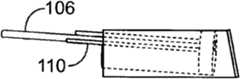
图1示出了佩戴在患者头部的简化的支撑结构。Figure 1 shows a simplified support structure worn on a patient's head.
图2示出了简化的耳道的视图。Figure 2 shows a simplified view of the ear canal.
图3示出了依据本发明的实施方式的示例性的引导块被插入耳道内。Figure 3 illustrates an exemplary guide block being inserted into an ear canal in accordance with an embodiment of the present invention.
图4示出了图3的引导块的各种细节。FIG. 4 shows various details of the boot block of FIG. 3 .
图5示出了引导块的稳定。Figure 5 shows the stabilization of the boot block.
图6示出了疼痛抑制剂的插入以及离子电渗疗法的启动。Figure 6 shows insertion of a pain inhibitor and initiation of iontophoresis.
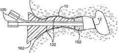
图7示出了组合的TM穿透器以及输送设备的放置。Figure 7 shows the placement of the combined TM penetrator and delivery device.
图8示出了TM的穿入。Figure 8 shows the penetration of TM.
图9示出了PE管的输送。Figure 9 shows the delivery of PE pipes.
图10示出了组合的穿透器和输送设备的移除。Figure 10 shows removal of the combined penetrator and delivery device.
图11示出了稳定印模(stabilizing impression)的移除。Figure 11 shows the removal of the stabilizing impression.
图12示出了依据本发明的一个实施方式的示例性的引导块系统。Figure 12 illustrates an exemplary boot block system in accordance with one embodiment of the present invention.
图13A示出了图12的引导块系统的进一步的细节;图13B为对应于图13A的横向视图。Figure 13A shows further details of the boot block system of Figure 12; Figure 13B is a lateral view corresponding to Figure 13A.
图14A-B示出了图12的引导块系统的详细的截面图。14A-B show detailed cross-sectional views of the boot block system of FIG. 12 .
图15A-C示出了当引导块系统处于患者耳中的适当位置时,由图12的内窥镜观察到的示例性视图。15A-C show exemplary views from the endoscope of FIG. 12 when the guide block system is in place in a patient's ear.
图16示出了处于患者耳中适当位置的引导块系统的前截面图。Figure 16 shows a front cross-sectional view of the guide block system in place in a patient's ear.
图17A-F示出了在患者耳中适当位置的引导块系统的部署。17A-F illustrate deployment of the guide block system in place in a patient's ear.
图18示出了设置成支撑离子电渗疗法模块(iontophoresis module)的示例性的支撑结构。Figure 18 illustrates an exemplary support structure configured to support an iontophoresis module.
图19示出了依据本发明的实施方式的示例性的离子电渗疗法模块。Figure 19 illustrates an exemplary iontophoresis module in accordance with an embodiment of the present invention.
图20为示出了图19离子电渗疗法模块的电子架构的示例性电路图。FIG. 20 is an exemplary circuit diagram illustrating the electronic architecture of the iontophoresis module of FIG. 19 .
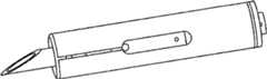
图21-22示出了用于组合的穿透器和输送设备-组合的PE管输送设备(PE Tube Delivery Device)(PETDD)的示例性的概念设计。21-22 show an exemplary conceptual design for a combined penetrator and delivery device - a combined PE Tube Delivery Device (PETDD).
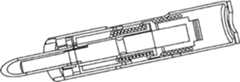
图23-27示出了用于组合的穿透器和输送设备-组合的PE管输送设备(PETDD)的致动器系统的一个实施方式。23-27 illustrate one embodiment of an actuator system for a combined penetrator and delivery device - combined PE tube delivery device (PETDD).
图28-32示出了用于组合的PE管输送设备(PETDD)的可选实施方式。Figures 28-32 illustrate an alternative embodiment of a combined PE tube delivery device (PETDD).
图33示出了用于PETDD的光学测距仪的一个示例性的实施方式。Figure 33 shows an exemplary embodiment of an optical range finder for PETDD.
图34A-B示出了用于PETDD的测距仪的可选择的实施方式。Figures 34A-B illustrate an alternative embodiment of a range finder for PETDD.
图35A-B示出了具有检耳镜、引导管稳定器(guide tube stabilizer)以及测距仪的组合特征的手持设备的实施方式。35A-B illustrate an embodiment of a hand-held device with combined features of an otoscope, guide tube stabilizer, and range finder.
图36A-B示出了用于引导块系统的工作通道的屏障的实施方式。36A-B illustrate an embodiment of a barrier for a working channel of a boot block system.
图37A-C示出了用于在X-Y方向定位PETDD的凸轮/偏心机构的实施方式。37A-C illustrate an embodiment of a cam/eccentric mechanism for positioning a PETDD in the X-Y direction.
图38B示出了通过使用图38A中示出的皮下注射针(hypo needle)形成于TM中的不带有瓣的弯曲洞。Figure 38B shows a curved hole without flaps formed in the TM by using the hypo needle shown in Figure 38A.
图39B示出了通过使用图39A中示出的鼓膜切开术矛状体形成于TM中的不带有瓣的笔直洞。Figure 39B shows a straight hole without flaps formed in the TM by using the myringotomy spear shown in Figure 39A.
图40B示出了通过使用图40A中示出的套管针形成于TM中的带有瓣的Y字型洞。Figure 40B shows the valved Y-shaped hole formed in the TM by using the trocar shown in Figure 40A.
图41A-C示出了包括中断的中间凸缘(interrupted medial flange)的不同的PE管形状。Figures 41A-C show different PE pipe shapes including interrupted medial flanges.
图42A-B示出了从切割工具的内部输送的PE管。42A-B show PE tubing delivered from the inside of a cutting tool.
图43A-B示出了从切割工具的内部输送的索环或T管型PE管。Figures 43A-B show grommet or tee-type PE tubing delivered from the inside of the cutting tool.
图44A-B示出了在切割工具的外侧输送的PE管。Figures 44A-B show PE tubing being delivered on the outside of the cutting tool.
图44C-D示出了具有切口以允许更容易地通过及其挠曲穿过TM的PE管上的凸缘。Figures 44C-D show a flange on a PE tube with cutouts to allow easier passage and flexing of it through the TM.
图45示出了将离子电渗疗法模块电极与引导块系统的工作通道或通气管组合的实施方式。Figure 45 shows an embodiment combining the iontophoresis module electrodes with the working channel or vent tube of the lead mass system.
图46A-B示出了用于稳定耳道内的引导块管(guide block tube)的多个纵向气球的使用。46A-B illustrate the use of multiple longitudinal balloons for stabilizing the guide block tube within the ear canal.
图47A-B示出了用于稳定耳道内的引导块管的多个周围气球的使用。47A-B illustrate the use of multiple peripheral balloons to stabilize the guide mass tube within the ear canal.
图48A-B示出了用于稳定耳道内的引导块管的柔顺气球的使用。48A-B illustrate the use of a compliant balloon for stabilizing the guide block tube within the ear canal.
图49A-B示出了用于稳定耳道内的引导块管的偏移气球的使用。49A-B illustrate the use of an offset balloon to stabilize the guide mass tube within the ear canal.
图50A-B示出了用于稳定耳道内的引导块管的气球中的辐条的使用。Figures 50A-B illustrate the use of spokes in a balloon to stabilize the guide mass tube in the ear canal.
图51A-B示出了用于稳定耳道内的引导块管的螺旋弹簧的使用。51A-B illustrate the use of coil springs to stabilize the guide block tube within the ear canal.
图52A-B示出了用于稳定耳道内的引导块管的泡沫中的线圈的使用。52A-B illustrate the use of coils in foam to stabilize the guide mass tube in the ear canal.
图53描绘了连接到引导块的远端的薄的聚合物屏障的实施方式。Figure 53 depicts an embodiment of a thin polymer barrier attached to the distal end of the guide block.
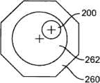
图54A-B示出了关于耳道的X-Y瞄准和Z距离测量。54A-B illustrate X-Y aiming and Z distance measurement with respect to the ear canal.
图55A-B示出了测距和瞄准实施方式,其包括安装在引导块的远端的细头发状元件(fine hair-like element)的使用。55A-B illustrate a ranging and targeting embodiment that includes the use of a fine hair-like element mounted at the distal end of the guide block.
图56A-B示出了测距和瞄准实施方式,其涉及激光器的使用。56A-B illustrate ranging and targeting implementations involving the use of lasers.
图57A-B示出了测距和瞄准实施方式,其涉及光学方法的使用。Figures 57A-B illustrate ranging and targeting implementations involving the use of optical methods.
发明详述Detailed description of the invention
本发明的实施方式提供用于在患者清醒且可移动的基于办公室的手术中给遭受复发性耳炎或具有渗出物的中耳炎的儿童的耳的目标组织提供无痛、同步、两侧治疗的系统和方法,其设计成能够控制儿童和父母的焦虑。Embodiments of the present invention provide a method for providing painless, simultaneous, bilateral therapy to target tissue of the ear of children suffering from recurrent otitis or otitis media with exudates in an office-based procedure where the patient is awake and mobile. Systems and methods designed to manage anxiety in children and parents.
在一个方面,本发明涉及具有用于将各种治疗设备与儿童的耳的目标组织对准的共用支撑结构的一套医疗设备。在一个实施方式中,这套医疗设备可用于将压力平衡(PE)管插入鼓膜中而不依靠全身麻醉。这套新颖的医疗设备使得对于患者的鼓膜中的PE管的放置能够在不要求全身麻醉的办公室手术实施中在短时间(例如30分钟)内完成;可以同时治疗两个耳(例如,同时两侧);适合于年幼患者(例如,18个月到7岁大),其中,焦虑度和最小干扰的控制是理想的。此治疗手术也得益于与传统的外科手术关联的风险的减小。In one aspect, the invention relates to a set of medical devices having a common support structure for aligning various therapeutic devices with target tissue of a child's ear. In one embodiment, this medical kit can be used to insert a pressure equalization (PE) tube into the eardrum without resorting to general anesthesia. This novel medical device enables the placement of a PE tube in a patient's tympanic membrane in a short period of time (e.g., 30 minutes) in an office procedure that does not require general anesthesia; side); suitable for young patients (eg, 18 months to 7 years old), where control of anxiety and minimal disturbance is ideal. This therapeutic procedure also benefits from the reduction of risks associated with traditional surgical procedures.
具有共用支撑结构的这套新颖的医疗设备包括用于经由引导块在耳道内支撑、对准和引导一个或多个医疗设备的设备;用于定位该引导块的设备;用于稳定该引导块的设备;用于在开始治疗处理之前对两耳施加局部疼痛抑制剂的设备;用于造影的设备;以及用于穿入鼓膜并用于输送PE管的设备。另外,该共用支撑结构与用于利用一个或两个声道吸引住患者的系统连接,其中,治疗处理可以与声道同步;或者视频,其中,治疗处理可以与该视频同步。以此种方式,在使用上述设备的任何组合时儿童患者被分散注意力。例如,当儿童患者正在听视频的声道时,声道的音量在关键时间增加,同时如果他/她没有被声道分散注意力,上面的设备也可产生可以以其它形式被患者听到的大声的噪音。这些医疗设备中的每一个在下文被更详细地描述。The novel set of medical devices having a common support structure includes means for supporting, aligning and guiding one or more medical devices within the ear canal via a guide block; means for positioning the guide block; means for stabilizing the guide block devices for application of topical pain suppressants to both ears prior to initiation of therapeutic treatment; devices for imaging; and devices for penetrating the tympanic membrane and for delivering PE tubes. In addition, the common support structure is interfaced with a system for engaging a patient with one or both audio channels, where therapeutic treatments can be synchronized with the audio channels; or video, with which therapeutic treatments can be synchronized. In this manner, the pediatric patient is distracted while using any combination of the above devices. For example, when a child patient is listening to the audio channel of a video, the volume of the audio channel is increased at critical times, and if he/she is not distracted by the audio channel, the above device can also produce noise that can be heard by the patient in other forms. Loud noise. Each of these medical devices is described in more detail below.
图1示出了简化的支撑结构1,其在患者清醒和直立时佩戴在患者头部上。该支撑结构1被设置成保持上文描述的一套或多套新颖的医疗设备2与患者的耳3对准。如可以从图1中见到的,支撑结构1可具有对准结构,该对准结构带有与第一耳接合的第一主体、与第二耳接合的第二主体以及围绕患者头部在第一主体和第二主体之间延伸的构件。Figure 1 shows a simplified support structure 1 which is worn on the patient's head when the patient is awake and upright. The support structure 1 is arranged to hold one or more sets of novel
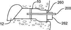
图2-10描述了可以通过使用该套医疗设备进行的一系列治疗手术,这套医疗设备具有共用支撑结构,该支撑结构用于将不同的治疗设备与儿童的耳的目标组织对准。图2示出了简化的耳道的视图。如可以在图2中见到的,耳道10为大约19mm长并且具有大约7mm的平均直径。耳道具有非均匀的形状,在鼓膜12或耳鼓12处终止。如上文阐述的,该套医疗设备可用于在不要求全身麻醉的非外科手术中将压力平衡(PE)管插入鼓膜。作为第一个步骤,图3示出了将依据本发明的实施方式的示例性引导块100插入耳道10内。如图4中示出的,引导块100包括位于其远端的泡沫块或盘102。该泡沫块102被设置成配合在耳道10内,靠近鼓膜12。该泡沫块102保持与引导管104对准。该引导管104延伸穿过泡沫块并且被设置成定位成靠近鼓膜(TM)。该引导管104在其远端具有柔软尖端105。泡沫块102也保持与管106对准,该管106可用于将药物输送进入泡沫块102和TM之间的空间。该管106还可用做用于图像抓取设备(image capture device)比如内窥镜的引导件。该泡沫块102还可以保持与用于在空间的处理过程中排放泡沫块102和TM之间的空间的通气管108对准。另外,泡沫块102还保持与电极和低规格电线110对准以启用离子电渗疗法模块。如图4中可见到的,插入的引导块100配合在耳道10内部,并且引导块的远端定位成靠近鼓膜12。在一个实施方式中,可以使用可穿过管106送入的原位视觉系统(in-situ vision system)将引导块100与放置的目标PE管对准。可选择地,该视觉系统可以被设置成支持距离记录(distance registration),使得可以控制引导块100和TM 12之间的距离。2-10 depict a series of therapeutic procedures that may be performed using the medical kit with a common support structure for aligning the different therapeutic devices with the target tissue of the child's ear. Figure 2 shows a simplified view of the ear canal. As can be seen in Figure 2, the
图5示出了耳道10内的引导块100的稳定。该引导块100可以通过围绕引导块插入可硬化的材料120而稳定在耳道10内。可注射的材料120具有可工作状态,该可工作状态允许调整以便在引导块支撑结构和耳的目标组织之间对准。该可注射的材料120还具有用于使引导块支撑结构相对于目标组织稳定的硬化状态。该可工作状态可以是时间相关的或时间致动的(time activated)。在一个实施方式中,印模材料可以在数分钟内硬化。在其它构造中,印模材料可以是可工作的,直到如下文描述的添加了硬化剂。FIG. 5 shows the stabilization of the
稳定的引导块100可用于接收模块,同时每个模块能完成不同的功能。例如,第一模块可用于测距/距离设置;然后,可以从引导块移除该模块并且可插入第二模块,该第二模块可以为离子电渗疗法单元。此后,移除离子电渗疗法单元且然后可以插入下一个模块(例如,致动器模块)。引导块100可用于药物输送/注射模块,该模块用于急性中耳炎,并且引导块100还可用于PE管输送模块,该模块用于带有渗出物的中耳炎。The
图6示出了例如在鼓膜切开术和放置PE管之前对耳施加局部疼痛抑制剂。以此种方式,鼓膜切开术和放置PE管可以在患者清醒时进行。局部疼痛抑制剂可以为带有或不带有肾上腺素的利多卡因。一旦疼痛抑制剂已经经过管106插入引导块100和TM 12之间的远端空间,其离子电渗疗法地通过将电极110耦合到离子电渗疗法模块4而被致动。该离子电渗疗法模块也可用在耳道中,以便输送抗生素和/或消炎剂,以便经鼓膜或经中耳腔的输送遍布发炎组织。引导块100和离子电渗疗法模块可用于不仅通过耳局部输送疼痛抑制剂。引导块100和离子电渗疗法模块可用于其它疗法比如黏液溶解剂、抗生素、类固醇、表面活性剂等等的局部输送,这些局部输送可以在鼓膜切开术和/或鼓膜穿刺术之前或之后,或者在TM的穿刺之前以帮助使组织定位和稳定以辅助实际切口。药物输送也可用在收缩的耳鼓的病例中。离子电渗疗法系统能够提供耐受性良好的方法,以便在相对短的时间内使用利多卡因对患者提供麻醉,使患者不遭受与此药物的系统性输送关联的症状。Figure 6 shows application of a topical pain suppressant to the ear, for example, prior to myringotomy and placement of a PE tube. In this way, myringotomy and placement of the PE tube can be performed while the patient is awake. The topical pain suppressant may be lidocaine with or without epinephrine. Once the pain suppressant has been inserted through the
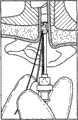
图7示出了依据本发明的一个实施方式的组合的TM穿透器和输送设备200的放置。组合的TM穿透器和输送设备200可以被插入输送系统引导件104。组合的TM穿透器和输送设备200一旦就位即可推进位于其远端的柳叶刀202以穿刺TM膜。一旦TM已被穿刺,可以收回柳叶刀202以便部署PE管204(图9)。应认识到,PE管可以和TM的穿刺同时和/或之后部署,而不仅是在柳叶刀被收回之后。而且,在一些实施方式中,可以在PE管的部署之前或之后抽吸TM的前面和/或后面的空间。Figure 7 illustrates placement of a combined TM penetrator and
在PE管的输送之后,如图10中示出的,移除组合的TM穿透器和输送设备200,并且随后也移除稳定材料和引导块,从而将PE管204留在TM中的适当位置,如图11中示出的。上面的手术中用到的这些医疗设备中的每一个的另外的细节如下文所述。After delivery of the PE tube, as shown in FIG. 10 , the combined TM penetrator and
带有瞄准和可视化系统的引导块Guide block with aiming and visualization system
图12-17示出了引导块的不同方面。依据本发明的实施方式的引导块被设置成插入耳道内,并且贴靠着耳道的软骨或骨部分稳定。引导块系统可包括瞄准元件(targeting element)以确保组合的TM穿透器和输送设备在鼓膜上的正确位置被瞄准并确认引导结构定位在距鼓膜的界定距离以内。该引导块系统还可以允许用于显像的内窥镜的插入。该引导块系统还可以包括用于插入离子电渗疗法系统电极、PE管输送设备、抽吸设备、冲洗设备以及用于输送治疗药剂的其它设备的工作通道。12-17 illustrate different aspects of the boot block. A guide block according to an embodiment of the invention is configured to be inserted into the ear canal and stabilized against the cartilage or bony part of the ear canal. The guide block system may include a targeting element to ensure that the correct location of the combined TM penetrator and delivery device on the eardrum is targeted and to confirm that the guide structure is positioned within a defined distance from the eardrum. The guide block system may also allow insertion of an endoscope for imaging. The guide block system may also include working channels for insertion of iontophoresis system electrodes, PE tubing delivery devices, suction devices, irrigation devices, and other devices for delivering therapeutic agents.
图12示出了依据本发明的一个实施方式的引导块系统100。如图12所示,引导块100在其远端具有泡沫块102。泡沫块102的尺寸可制定成具有不同的外直径(例如,以2mm的增量从大约3mm增加到大约13mm),以匹配成年患者以及儿科患者的不同尺寸的耳道。该泡沫块的厚度选定成在耳道内占用最小量的轴向空间,同时提供足够的厚度以便在耳道内提供相对牢固的初始放置,起到用于印模材料的屏障的作用,并且起到用于利多卡因和肾上腺素的屏障的作用并防止溶液流出耳。泡沫块或盘允许在耳道的横截面内的可变的定位。在插入引导块100的过程中泡沫块102可以被压缩,以便最小化由泡沫盘接触耳道引起的患者不适。泡沫慢速恢复的性质允许它在插入过程中保持压缩,并且一旦达到正确放置就膨胀以便填充耳道的横截面。泡沫盘102可以随后起到屏障的作用,防止印模材料流进泡沫盘102和TM之间的空间内。除了上面描述的闭孔泡沫之外,盘102可以由柔软的开孔泡沫制成。柔软的开孔泡沫可以使用护套压缩,该护套可以被拉回以便弹开泡沫-其起到屏障的作用。泡沫将快速地弹起-不像闭孔泡沫那样“缓慢”释放。护套可以为延伸整个(或接近于整个)引导块腔的长度的管。护套还可以为带有线或其它装置的短套管,使得当套管被拉回时,其保留主轴不附着到印模材料。该护套还可以为“撕掉”的样式。Figure 12 illustrates a
图12还显示了引导块系统100被设置成与用于离子电渗疗法模块的电极110、用于显像的内窥镜120以及用于将印模材料输送进入耳道的填充喷嘴130配合。Figure 12 also shows the
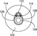
图13A示出了图12的引导块系统的另外的细节,而图13B为对应于图13A的横向视图。如图13A-B所示,引导块100包括工作通道104、内窥镜通道112以及一个或多个通气管114。在工作通道104的近端,该引导块100包括单向阀124,而在内窥镜通道112的近端,该引导块100包括内窥镜夹具122。单向阀124允许离子电渗疗法溶液被注射进入引导块100的远端和TM之间的空间,而离子电渗疗法溶液不反向泄漏流出工作通道104。在一个实施方式中,该单向阀被设置成在其被放置在工作通道中时围绕离子电渗疗法电极密封。内窥镜夹具122允许内窥镜相对于引导块锁在适当位置,以便稳定内窥镜图像并使操作者的一只手自由。Figure 13A shows additional details of the boot block system of Figure 12, while Figure 13B is a lateral view corresponding to Figure 13A. As shown in FIGS. 13A-B ,
图14A-B示出了图12的引导块系统的详细的截面图。图14A-B示出了引导块100的元件的一种示例性布置。图14A-B还显示了套管126可以围绕工作管104、通气管114以及内窥镜通道112。另外,图14A-B还示出了使用粘合剂层128将套管126与泡沫块102连接;以及该套管126包括位于其内部表面上的粘合剂层130以帮助牢固地保持工作管104、通气管114以及内窥镜通道112。14A-B show detailed cross-sectional views of the boot block system of FIG. 12 . 14A-B illustrate one exemplary arrangement of elements of
工作通道104可以由医疗级透明塑料管件制成。工作通道104为用于输送离子电渗疗法溶液、离子电渗疗法电极以及注射冲洗溶液的导管。工作通道104也是用于靠近目标组织区域输送组合的TM穿透器和输送设备200的导管。该工作通道104也是用于靠近目标组织区域输送瞄准装置的导管。工作通道104的远端可以向下成锥度,以防止辅助设备经过工作通道的远端插入,从而防止对TM的任何意外损害。在一个实施方式中,工作通道的优选长度为在5-10cm之间,并优选为大约7cm。Working
内窥镜通道112可以由医疗级透明塑料管件制成以允许通过壁显像,并且其尺寸制定成能配合小的(即1mm)柔性内窥镜。透明性及因而引起的显像对于检测印模材料中的空穴、局部疼痛抑制剂中的气泡以及将内窥镜监视器上的图像与引导块的位置对准是有用的。可以使用其它引导块部件上的颜色或特征来记录内窥镜图像。The
一个或多个通气管114允许在放入离子电渗疗法溶液时空气逃逸,防止在离子电渗疗法溶液注射过程中鼓膜上有过度的压力,并且还用于减轻在从耳道移除任何设备时耳道内的任何负压。通气管114的尺寸制定成允许减轻压力,该压力在注射离子电渗疗法溶液的过程中可以为正的,而在移除引导块的过程中可以为负的。通气管114的尺寸制定成允许以最小量的阻力减轻压力,同时保持小的横截面面积,使得表面张力不允许离子电渗疗法溶液反向泄漏流出工作通道104。对于所有管和通道的壁厚度选定成在插入它们的过程中确保充分的柱强度(column strength)以抵抗挠曲或压碎,而且是坚固的足以保持柔性并具有最小横截面覆盖区。肋、凸块或其它突起可以沿着引导块管和通道的长度被添加,以帮助产生与印模材料的互锁。One or
图15A-C示出了当引导块系统处于患者耳中适当位置时由图12的内窥镜观察到的示例性视图。如上文阐述的,通过使用其它引导块部件上的颜色或特征,内窥镜图像可以是互为参照的。图15A显示了通过透明的内窥镜通道112由内窥镜观察到的通气管114。也可以看到TM。图15B显示了通过透明的内窥镜通道112由内窥镜观察到的带颜色的工作通道104。也可以看到TM。图15C显示了这样一种图像,其中内窥镜通道112中的一条颜色可以帮助内窥镜图像的观察者正确地判断。15A-C show exemplary views from the endoscope of FIG. 12 when the guide block system is in place in a patient's ear. As set forth above, endoscopic images may be cross-referenced by using colors or features on other guide block components. FIG. 15A shows the
图16示出了处于患者耳中适当位置的引导块系统100的前截面图。如在图16上显示的,该引导块处于右耳中适当位置。印模材料120围绕引导块系统填充进入以将其牢固定位。泡沫盘102被放置在TM 12的旁边以及耳道的骨结构或软骨结构内。印模材料120围绕引导块管注射进入耳道,填充耳道并延伸进入耳壳或外耳。印模材料120有助于相对于TM稳定引导块。引导块100和TM 12之间的工作空间150可填充有离子电渗疗法溶液。Figure 16 shows a front cross-sectional view of the
填充喷嘴130用于输送印模材料。填充喷嘴130可以被放置在耳道外部或靠近耳道的内侧。该填充喷嘴130可以具有大孔和有锥度的远端,以便通过最大化印模材料120在其离开填充喷嘴130时的速度和动量来确保围绕引导块完整地填充耳道空间。可选择地,填充喷嘴130可在耳道中放置得更深并随着耳道被印模材料填充而收回,以便首先通过在耳道内紧挨着泡沫盘102填充而确保完全填充。填充喷嘴130可以具有靠近其远端的一个或多个偏移洞,该偏移洞可以在位于喷嘴的远端的轴向洞之外位于填充喷嘴130的侧壁上或者代替位于喷嘴的远端的轴向洞位于填充喷嘴130的侧壁上。填充喷嘴130的一个或多个侧洞可提高设备的安全度,因为按照此种布置,印模材料不在泡沫盘102处直接地注射,这可能引起印模材料经过泡沫盘102的侧面的泄漏。通过更好地达到可能以其它形式堵塞的凹穴或空穴,填充喷嘴的一个或多个侧洞可以帮助促进完整的填充。可选择地,可以使用多于一个填充喷嘴,以便周边地围绕引导块以便确保更好的和更完整的填充。该一个或多个喷嘴可以从共用头部分出或者可以是分离的填充喷嘴。引导块中也可以有用于填充的腔。在那样的情况中,填充喷嘴可以连接到引导块,并因此可以从该块填充返回到耳道中的开口。这可以确保始终如一的填充和空穴的消除。The filling
填充喷嘴可以具有对于尖端孔的位置的深度和方位记号,甚至在尖端不能被看到时,尖端孔的位置的深度和方位可以被探测到。这些深度和/或方位记号可以放置在填充喷嘴130的近端部分上。深度记号可以与引导块的部分对齐,以指示喷嘴的尖端邻近于泡沫盘102。可以与深度记号分离或组合的方位记号可用于指示喷嘴孔的定向。The filling nozzle can have depth and azimuth markings for the location of the tip hole so that the depth and azimuth of the location of the tip hole can be detected even when the tip cannot be seen. These depth and/or orientation markings may be placed on the proximal portion of
图17A-F示出了在患者耳中适当位置的引导块系统的部署。图17A显示,在内窥镜显像下插入引导块(图17B)之前,泡沫盘102被压缩。随后在图17C中,用印模材料填充耳道。在图17D中,一旦印模材料已经硬化,将含有疼痛抑制剂的溶液注射进入工作空间。在图17E中,插入离子电渗疗法电极以输送离子电渗疗法。随后在图17F,移除引导块和印模材料。17A-F illustrate deployment of the guide block system in place in a patient's ear. Figure 17A shows the
引导块系统也被设置成实现离子电渗疗法电极的显像。为了达到此目的,离子电渗疗法电极的尖端可经过内窥镜看见,以确保电极与离子电渗疗法溶液接触并且不被可能降低麻醉作用的气泡或气穴围绕。A guide mass system is also configured to enable visualization of the iontophoresis electrodes. To achieve this, the tip of the iontophoresis electrode is visible through the endoscope to ensure that the electrode is in contact with the iontophoresis solution and is not surrounded by air bubbles or air pockets that could reduce anesthesia.
本发明的实施方式的某些方面涉及可以防止印模材料渗入经过引导块的远端的特征。如上文描述的,该引导块系统包括安装在引导块管的远端上的泡沫盘,以便防止印模材料流动进入引导块的远端和TM之间的空间。图53描绘了其中薄的聚合物屏障连接到引导块的远端的实施方式。依据本发明的此实施方式,泡沫盘102可以被增大或者甚至被连接到引导块100的远端的薄聚合物屏障162替换。薄的聚合物屏障162在其近端开放,并且其被设置成像配合在垃圾箱内的垃圾袋一样配合进入耳道。当印模材料120被注射进屏障162的近端开口时,其流动进入耳道,贴靠着耳道10的壁使屏障162膨胀。屏障162将防止印模材料120流动经过引导块100的远端,因为屏障162在其远端闭合并与引导块连接。屏障162的开放端部的尺寸可制定成像示出的那样是大的或可以是小的,比如luer配件(luer fitting)。印模材料也可以被注射进入放置在引导块工作通道或通气管上的柔顺气球或袋内。在此构造中,防止了印模材料移动进入引导块和TM之间的空间。Certain aspects of embodiments of the invention relate to features that may prevent impression material from seeping past the distal end of the guide block. As described above, the guide block system includes a foam disc mounted on the distal end of the guide block tube in order to prevent impression material from flowing into the space between the distal end of the guide block and the TM. Figure 53 depicts an embodiment in which a thin polymeric barrier is attached to the distal end of the guide block. According to this embodiment of the invention, the
下面提供了对于上文描述的引导块系统的各种附加的细节。如上文描述的,在耳道的高度可变的解剖学中使用引导块系统,以便提供用于接下来的要求精度和准确度的步骤,例如用于放置PE管的稳定平台。因此,引导块的放置和固定优选地应当是快速的。固定应当相对于TM是牢固和刚性的,并且部署引导块需要能够填充耳道中复杂的、不同心的以及敏感的区域,以便将引导块固定就位。例如,在引导块的远端使用的泡沫盘在输送过程中被压缩成小的轮廓,以避免与敏感的耳道壁接触。然而,泡沫盘随后膨胀以填充引导件和耳道之间的空间。泡沫盘可以为记忆泡沫。该记忆泡沫可以为类似于那些用在耳塞中的慢速恢复氨基甲酸乙酯或乙烯基泡沫。该记忆泡沫的优势在于其简单、当前可得、成本低并且可容易地以一系列的尺寸来生产。该印模材料可以为催化泡沫(catalyzing foam)。该催化泡沫可以为两部分泡沫,该两部分泡沫通过添加两种成分产生可以迅速地在耳道中建立起的泡沫。催化泡沫的优势在于其在输送过程中具有非常小的轮廓,其可以配合进入任何形状的耳道并且其可以被形成为具有任何变化的硬化速度。除使用催化泡沫来稳定耳道内的引导块系统之外,接下来的可选择的稳定方案也在本发明的实施方式的范围内。这些可选择的稳定方案包括气球、可变形的机械元件的使用以及散装材料填充,并且在下文中描述。Various additional details to the boot block system described above are provided below. As described above, the guide block system is used in the highly variable anatomy of the ear canal in order to provide a stable platform for subsequent steps requiring precision and accuracy, eg for placement of PE tubes. Therefore, placement and fixing of the guide blocks should preferably be fast. Fixation should be firm and rigid relative to the TM, and deployment of the guide mass needs to be able to fill complex, non-concentric and sensitive areas in the ear canal in order to secure the guide mass in place. For example, the foam disk used at the distal end of the guide block is compressed into a small profile during delivery to avoid contact with the sensitive ear canal wall. However, the foam disc then expands to fill the space between the guide and the ear canal. The foam disc can be memory foam. The memory foam can be a slow recovery urethane or vinyl foam similar to those used in earplugs. The advantages of this memory foam are its simplicity, current availability, low cost and easy production in a range of sizes. The impression material may be a catalyzing foam. The catalytic foam may be a two-part foam which, by adding two components, produces a foam that builds rapidly in the ear canal. The advantage of catalytic foam is that it has a very low profile during delivery, it can fit into any shape of ear canal and it can be formed to have any varying rate of hardening. In addition to the use of catalytic foam to stabilize the guide mass system within the ear canal, subsequent alternative stabilization solutions are within the scope of embodiments of the present invention. These alternative stabilization schemes include balloons, the use of deformable mechanical elements, and bulk material filling, and are described below.
图46A-B示出了用于将引导块管稳定在耳道内的多个纵向气球的使用。气球的使用是有优势的,因为气球在将它们插入的过程中具有小轮廓;它们快速地立起和拆卸。另外,气球的使用使得能在不同形状和尺寸的耳道内稳定引导块。图46A-B中示出的布置允许引导块管被放置成经过选择性地成形或充气的气球在耳道中偏移。46A-B illustrate the use of multiple longitudinal balloons to stabilize the guide block tube within the ear canal. The use of balloons is advantageous because balloons have a low profile during their insertion; they are erected and dismantled quickly. In addition, the use of a balloon allows stabilizing the guide block in ear canals of different shapes and sizes. The arrangement shown in Figures 46A-B allows the guide block tube to be placed offset in the ear canal via a selectively shaped or inflated balloon.
图47A-B示出了用于稳定耳道内的引导块管的多个周围气球的使用。图47A-B中示出的布置可用于通过使气球在若干位置膨胀来沿着耳道长度配合耳道的变化的直径。此实施方式的优势在于气球不必与耳道的敏感区域接触;可以使用一个设备处理一系列的耳道尺寸和构造;且管的连续膨胀可以允许相对于TM上的目标位置更好地调整引导块管的主轴线。47A-B illustrate the use of multiple peripheral balloons to stabilize the guide mass tube within the ear canal. The arrangement shown in Figures 47A-B can be used to fit the varying diameter of the ear canal along the length of the ear canal by inflating the balloon in several locations. The advantages of this embodiment are that the balloon does not have to come into contact with sensitive areas of the ear canal; a range of ear canal sizes and configurations can be addressed with one device; and continuous expansion of the tube can allow better adjustment of the guide block relative to the target location on the TM The main axis of the tube.
图48A-B示出了用于稳定引导块管或起到耳道内的屏障作用的柔顺气球的使用。如图48A-B中示出的,单个气球可以按类似于乳胶柔顺气球导管(latex compliant balloon catheter)的方式膨胀以柔和地填充引导块管和耳道之间的整个空间。48A-B illustrate the use of a compliant balloon to stabilize the introducer tube or to act as a barrier within the ear canal. As shown in Figures 48A-B, a single balloon can be inflated in a manner similar to a latex compliant balloon catheter to gently fill the entire space between the guide block tube and the ear canal.
用于稳定引导块的基于气球的方案可以具有填充有空气、水、盐水或类似物质的一个或多个气球。可选择地,这些气球可以填充有其它物质,以便借助于更刚性的气球更加牢固地锚固。一种这样的填充可以为两部分反应系统(two-part reaction system),其中,首先以一种物质部分地填充气球,并且然后添加第二种物质。这两种物质起化学反应形成较硬的物质。这两种物质中的任意一种可以为粉末、液体或气体形式。另一种这样的填充可以为起反应并且体积膨胀以确保完全填充耳道体积而不在耳道上放置多余的压力的两部分或一部分系统。另一种这样的填充可以为其中填充为UV致动的两部分或一部分系统。附加的物质可以在引导块稳定程序结束被引入以促进膨胀的气球的移除。Balloon-based solutions for stabilizing the guide mass may have one or more balloons filled with air, water, saline, or similar substances. Optionally, these balloons may be filled with other substances for more secure anchoring with more rigid balloons. One such filling may be a two-part reaction system, wherein the balloon is first partially filled with one substance, and then the second substance is added. These two substances react chemically to form a harder substance. Either of these two substances can be in powder, liquid or gas form. Another such filling may be a two-part or one-part system that reacts and expands in volume to ensure complete filling of the ear canal volume without placing excess pressure on the ear canal. Another such filling could be a two-part or one-part system where the filling is UV actuated. Additional substances may be introduced at the end of the boot block stabilization procedure to facilitate removal of the inflated balloon.
图49A-B示出了用于将引导块管稳定在耳道内的偏移气球的使用。如可以在图49A-B见到的,为了允许引导块管相对于耳道不同心,该气球与引导块管不同心。引导块管相对于气球的不同心放置的使用也可以通过上面图47-48中描述的实施方式实施。此外,引导块管相对于气球的不同心放置也可以通过泡沫块中的偏移洞实施。49A-B illustrate the use of an offset balloon to stabilize the guide block tube within the ear canal. As can be seen in Figures 49A-B, the balloon is not concentric with the guide block tube in order to allow the guide block tube to be non-concentric with respect to the ear canal. The use of non-concentric placement of the guide block tube relative to the balloon can also be implemented with the embodiments described above in FIGS. 47-48. In addition, non-concentric placement of the guide block tube relative to the balloon can also be implemented through offset holes in the foam block.
如上文阐述的,一个可选择的稳定方案包括可变形的机械元件(deformable mechanical element)的使用。该可变形的机械元件包括结构元件,该结构元件被移位使得元件的复原力作用在耳道壁上以稳定引导块系统。可变形的机械元件的使用可与上文描述的泡沫或基于气球的方法组合。As explained above, an alternative stabilization solution involves the use of deformable mechanical elements. The deformable mechanical element comprises a structural element which is displaced such that the restoring force of the element acts on the wall of the ear canal to stabilize the guide block system. The use of deformable mechanical elements can be combined with the foam or balloon-based approaches described above.
图50A-B示出了用于稳定耳道内的引导块管的气球中的辐条的使用。如图50A-B示出的,可延展的辐条或肋在引导块管和围绕引导块管的气球之间延伸,使得例如在气球需要关于引导块管不同心时,辐条引导气球充气。Figures 50A-B illustrate the use of spokes in a balloon to stabilize the guide mass tube in the ear canal. As shown in Figures 50A-B, the malleable spokes or ribs extend between the guide block tube and the balloon surrounding the guide block tube so that the spokes guide inflation of the balloon, eg, when the balloon needs to be out of center with respect to the guide block tube.
图51A-B示出了用于稳定耳道内的引导块管的螺旋弹簧的使用。如图51A-B可以见到的,螺旋弹簧的尺寸制定成配合在耳道内,其中,弹簧的复原力试图保持圆柱形,从而稳定耳道内的引导块系统。51A-B illustrate the use of coil springs to stabilize the guide block tube within the ear canal. As can be seen in Figures 51A-B, the coil spring is sized to fit within the ear canal, wherein the spring's restoring force attempts to maintain a cylindrical shape, thereby stabilizing the guide block system within the ear canal.
图52A-B示出了用于稳定耳道内的引导块管的泡沫中的线圈的使用。如图52A-B中描绘的,泡沫中的形式为线圈肋的弹簧元件辅助稳定方案的膨胀速度和力。52A-B illustrate the use of coils in foam to stabilize the guide mass tube in the ear canal. As depicted in Figures 52A-B, spring elements in the form of coiled ribs in the foam assist in stabilizing the expansion speed and force of the solution.
如上文阐述的,一个可选择的稳定方案包括散装材料填充的使用。如上文描述的,一个稳定方案包括催化泡沫的使用以稳定耳道内的引导块系统。一种类型的催化泡沫为两部分乙烯基聚硅氧烷印模材料,该乙烯基聚硅氧烷印模材料被注射进入耳道,像粘性材料一样围绕引导块管,随后,经过一段时间,该乙烯基聚硅氧烷印模材料硬化以提供引导块系统在耳道内的锚固。基于已知的耳科学方法和材料,此印模材料方案能够使用耳道上的最小量的压力来填充耳道空间。通过使用催速剂调整它们的固化速度或固化硬度,可以改进已知方法和材料以便减少患者不适,其中,催速剂的使用包括使用化学反应催速剂、电力、UV和/或热。如本文这样使用热提供附加的益处,因为将材料加热到接近体温可以使患者更舒适,并且较低的温度差使患者的不快较小。另外,热也可以允许稳定材料可能流动得更快并因此实现更好的填充。As set forth above, an alternative stabilization solution involves the use of bulk material fill. As described above, one stabilization solution involves the use of catalytic foam to stabilize the guide mass system within the ear canal. One type of catalytic foam is a two-part vinyl polysiloxane impression material that is injected into the ear canal, surrounds the guide block tube like a viscous material, and then, over a period of time, The vinyl polysiloxane impression material hardens to provide anchoring of the guide mass system within the ear canal. Based on known otological methods and materials, this impression material solution is able to fill the ear canal space with a minimal amount of pressure on the ear canal. Known methods and materials can be improved to reduce patient discomfort by adjusting their cure speed or cure hardness using accelerators, including the use of chemical reaction accelerators, electricity, UV and/or heat. Using heat as herein provides additional benefits, as heating the material to near body temperature can make the patient more comfortable, and the lower temperature differential makes the patient less uncomfortable. In addition, the heat may also allow the stabilizing material to possibly flow faster and thus achieve better filling.
本发明的实施方式的某些方面涉及用于防止或最小化耳道的摩擦同时允许在耳道内穿入和稳定引导块的方法和设备。图36A-B示出了用于引导块系统的工作通道的屏障的实施方式。图36A示出了耳道10内的引导块系统100的工作通道104的一部分,以及工作管的远端相对于TM 12的相对位置。如可以见到的,可在工作通道104的远端使用屏障结构170。屏障结构170被展示为在其被插入耳道10时处于其折叠状态。一旦就位,屏障结构170被展示为处于其非折叠状态或展开状态。屏障结构170可以包括柔软且光滑的材料(例如聚硅酮),其成形为产生可由位于屏障结构170的内部或者邻接屏障结构170的棚架结构172支撑的罩状结构(shroud-like structure)。该棚架结构172可以由通过工作通道进入的激励电缆展开。在操作中,使用上面描述的屏障结构170,工作通道104可以在“无擦伤”状态被推进耳道,并随后贴靠着耳道10在径向方向展开,从而最小化对于患者的摩擦和不适。可选择地,可使用由最小化耳道的摩擦的非常柔软的材料制成的输送护套以类似于自膨胀支架展开的方式包围引导块系统并将引导块系统输送进入耳道。该非常柔软的材料可以由胶原制成。Certain aspects of embodiments of the invention relate to methods and apparatus for preventing or minimizing friction of the ear canal while allowing penetration and stabilization of the guide block within the ear canal. 36A-B illustrate an embodiment of a barrier for a working channel of a boot block system. 36A shows a portion of the working
离子电渗疗法系统iontophoresis system
如图18中所示,一种可以被支撑结构1支撑的医疗设备为离子电渗疗法模块4。图18示出了当被设置成支撑离子电渗疗法模块4时的图1的支撑结构。如图18可以见到的,离子电渗疗法模块4靠近外耳3对准,并且包括稳定单元和接地电极5以及电池区域6,以及带有其相关的电极的离子电渗疗法单元,以及耳塞和注射口7。该离子电渗疗法模块4包括注射口8和排放口9。稳定电极元件可以被设置成围绕耳佩戴。接地电极11可以被佩戴在耳后面,并且可以通过使用生物兼容的粘合剂保持对准。耳机部分(ear piece portion)12可以被设置成安放在耳道的开口中并闭合耳道并使得能够注射和排放。电极线可以被形成或退火到预定形状以便舒适地配合在患者的耳周围,类似于用于手机和其它电子设备的小型耳机。One type of medical device that may be supported by the support structure 1 is an iontophoresis module 4 as shown in FIG. 18 . FIG. 18 shows the support structure of FIG. 1 when arranged to support an iontophoresis module 4 . As can be seen in Figure 18, the iontophoresis module 4 is aligned close to the
图19-20用于展示离子电渗疗法模块的各个方面。如图19示出的,依据本发明的一个实施方式的离子电渗疗法模块300可以为电池驱动的一次性电子设备310,该一次性电子设备310使用单独的返回电极贴片(return electrode patch)306对两个电极(每个耳一个)302A-B提供调节电流。该电极302A-B被设置成配合在引导块内,对于每个引导块各设置一个电极。该调节电流用于对鼓膜施加局部麻醉或其它治疗成分的离子电渗疗法过程。如图19示出的,离子电渗疗法模块300可以为尺寸约如名片大小的小电子设备,该小电子设备带有用于操作的LCD显示器308以及若干按钮312。另外,离子电渗疗法模块可以与返回电极贴片共同定位,以便最小化松散线的量以及整体封装尺寸。在此实施方式中,该返回电极贴片将永久地或者通过金属搭扣或其它导电连接机构连接到离子电渗疗法模块,并且整个组件随后经过返回电极贴片附着到患者的皮肤(例如颈部后部的皮肤),从而将离子电渗疗法模块固定在医师容易接近但患者不容易接近的位置。19-20 are used to illustrate various aspects of the iontophoresis module. As shown in FIG. 19, an
图45示出了将离子电渗疗法模块的电极与引导块系统的工作通道或通气管结合的实施方式。如图45示出的,管104M在其尖端和尾部具有导电区域,并且在其尖端和尾部之间是绝缘的。此种将离子电渗疗法模块的电极与引导块系统的工作通道或通气管结合的构造可以消除通过工作通道或通气管输送分离的电极的需要,从而使手术加速。Figure 45 shows an embodiment combining the electrodes of the iontophoresis module with the working channel or vent tube of the lead mass system. As shown in Figure 45, tube 104M has conductive regions at its tip and tail, and is insulating between its tip and tail. This configuration of combining the electrodes of the iontophoresis module with the working channel or vent of the lead block system may eliminate the need to deliver a separate electrode through the working channel or vent, thereby speeding up the procedure.
下文描述了离子电渗疗法模块300的操作。用户可以通过从单元的后部拉小的塑料凸出物来接通离子电渗疗法模块。此凸出物被设计成保持电池不为电路供电,直到希望供电。在拉动凸出物之后,电池将开始为电路供电并且LCD 308将发光。接下来,用户可以通过位于外壳背面的夹具将该单元夹到患者的领子的后部。一旦该外壳被固定,返回电极贴片就可以被放置在颈部的后部。接下来的步骤是将麻醉剂溶液施加进入患者的耳内并定位电极。一旦在一个侧面完成,该侧面可以独立于另一耳被激活。例如,如果左电极首先被放置,则用户将按压主单元上的“左耳开始”按钮以启动自动预编程的电流输送次序,以从0斜升的电流开始。同时,用户可以将右耳电极放进患者的右引导管内。一旦被正确地放置,则用户可以按压“右耳开始”按钮以便独立地开始将电流输送到右耳。对于每个耳,可以在LCD 308上显示进度条。该进度条用框中填充的面积来表示,该进度条从空开始,并随着电荷被输送而填充直到其完全填充并且该过程完成。一旦电流输送开始,用户就等待设备经过听觉蜂鸣声发出其被完成还是有问题的信号。在设备对每个耳输送全部剂量的电流之后,对于每个耳的进度条被填充并且该系统可以输送短系列的三个蜂鸣声以发出成功完成的信号。一旦该设备发出过程被完成的信号,设备就可以自动地切断。在此时刻,用户可以移除电极,并且可以开始移除多余的利多卡因并清理该区域的过程。此外,这可以独立地在一个侧面进行,而不影响另一侧面的正常的设备操作。The operation of the
在过程中的任何时间,可以通过按压左按钮或右按钮来暂停输送到电极的电流。该系统将斜降通向该电极的电流。用户也可以通过按压停止按钮而一次同时暂停两个电极。这将引起系统斜降通向两个电极的电流。在任一情形中,用户可以通过按压左按钮或右按钮而继续该过程。这将引起系统斜升用于该电极的电流并在被暂停之前在电流保持切断之处继续输送总电荷。在离子电渗疗法的电流输送循环结束时,电流将斜降至0。一旦两侧已经完成离子电渗疗法并且已经移除电极,则也可以移除返回贴片并且丢弃整个单元。在一个小时的时间之后或任何选定的单位时间之后,电源可以自动地切断。该单元被设计成只允许使用一次并且不能被返回到接通。另一个实施方式使得在一次使用后电流输送功能不能起作用,但是随后实现附加的功能,比如游戏、钟等等,以便患者在手术之后使用。如果有错误,则系统可以连续地发出一系列的长蜂鸣声。可选择地,或者除该系列的长蜂鸣声之外,可以使用视觉装置,以便不干扰患者。例如,位于该单元的后部或其它难以达到的位置上的闪烁的光将不大可能被患者注意到可能引起这样的错误的情况包括:探测到开路或者探测到过流情况。在开路的情况中,该设备将通过控制的电流斜降来自动地停止对患者输送电流,并且用户可以通过按压适当的开始按钮来重新开始输送。在过流的情况中,该设备在已经探测到内部错误后,将自动地停止通向两个电极的全部电流,将不再重新启动,并且该设备应该被丢弃。对于这两种情况,适当的信息被显示在LCD屏幕308上。At any time during the procedure, current delivery to the electrodes can be paused by pressing the left or right button. The system will ramp down the current to the electrode. The user can also pause both electrodes at once by pressing the stop button. This will cause the system to ramp down the current to both electrodes. In either case, the user can continue the process by pressing the left or right button. This will cause the system to ramp up the current for that electrode and continue delivering the total charge where the current remains off before being paused. At the end of the iontophoresis current delivery cycle, the current will ramp down to zero. Once both sides have completed iontophoresis and the electrodes have been removed, the return patch can also be removed and the entire unit discarded. After a period of one hour or any selected unit of time, the power may be automatically cut off. The unit is designed to be used only once and cannot be turned back on. Another embodiment disables the current delivery function after one use, but then enables additional functions, such as games, clocks, etc., for use by the patient after surgery. If there is an error, the system can emit a series of long beeps in succession. Alternatively, or in addition to the series of long beeps, a visual device may be used so as not to disturb the patient. For example, a flickering light located on the rear of the unit or other hard-to-reach location would be less likely to be noticed by the patient. Conditions that could cause such errors include detection of an open circuit or detection of an over-current condition. In the event of an open circuit, the device will automatically stop delivering current to the patient with a controlled current ramp down, and the user can restart delivery by pressing the appropriate start button. In the event of an overcurrent, the device, after having detected an internal error, will automatically stop all current to both electrodes, will not restart, and the device should be discarded. For both cases, the appropriate information is displayed on the
图20为示出了用于图19的离子电渗疗法模块的一种电子架构的示例性的电路图。一旦从单元的后部移除塑料凸出物,两个3V的电池立即开始对电路供电。该电池提供输送非常稳定的5V输出的LP2975电压调节器。该5V输出用于提供给微处理器(例如Atmel ATtiny 261)、数手-模拟转换器(DAC)转换器(例如Maxim MCP4922)、电流感应运算放大器(例如LM358)以及操作者界面的所有部件(按钮、蜂鸣器、LCD)。微处理器控制紧急停止按钮的大部分功能以斜降通向两个电极的电流;-用于感应输送到每个电极的电流的模拟输入;串行外设接口(SPI)通讯以为DAC设置基准;用于蜂鸣器和LCD的控制信号。在微处理器的外部,6V的电池电源驱动MAX5028DC-DC转换器,该转换器将电池电压转换成30V输出。此输出被用作恒定电流单元的导轨电源(rail power)。该恒定电流单元可以被设计成使用两个可选形式中的一个。第一种可选形式使用将差分输入电压(控制信号)转换成输出电压,并最终基于选定的感应电阻器转换成电流的运算放大器(Op-Amp),比如LM358。第二种技术使用运算跨导放大器(OTA),该运算跨导放大器以类似于Op-Amp的形式操作,因为其被差分输入电压控制,但是其基于外部提供的偏压电流驱动输出电流。FIG. 20 is an exemplary circuit diagram illustrating an electronic architecture for the iontophoresis module of FIG. 19 . Once the plastic tab is removed from the rear of the unit, the two 3V batteries begin powering the circuit immediately. The battery provides an LP2975 voltage regulator delivering a very stable 5V output. This 5V output is used to supply microprocessors (such as Atmel ATtiny 261), digital-to-analog converter (DAC) converters (such as Maxim MCP4922), current sense operational amplifiers (such as LM358), and all parts of the operator interface ( button, buzzer, LCD). Microprocessor controls most functions of emergency stop button to ramp down current to both electrodes; - Analog input for sensing current delivered to each electrode; Serial Peripheral Interface (SPI) communication to set reference for DAC ; Control signal for buzzer and LCD. External to the microprocessor, a 6V battery supply drives the MAX5028 DC-DC converter, which converts the battery voltage to a 30V output. This output is used as the rail power for the constant current unit. The constant current unit can be designed to use one of two alternatives. The first optional form uses an operational amplifier (Op-Amp), such as the LM358, that converts a differential input voltage (control signal) into an output voltage and finally into a current based on a selected sense resistor. The second technique uses an operational transconductance amplifier (OTA), which operates similar to an Op-Amp in that it is controlled by a differential input voltage, but drives an output current based on an externally provided bias current.
微处理器使用DAC对电流源设置基准电压水平。该微处理器经过串行协议SPI通讯到DAC。恒定电流源使用来自微处理器的控制信号(0-5V)以便依据预定的倾斜形状将电流从0斜升至1mA。该DC-DC转换器提供足够高的干线电压(30V),以允许恒定电流源基于22.5kOhm的最大期望体电阻驱动1mA的电流。该体电阻基于由本文的受让人执行的调查。在被分配的输送时间之后,微处理器将控制信号斜降返回到0V,这将由电流源输送的电流减小到0。The microprocessor uses the DAC to set the reference voltage level for the current source. The microprocessor communicates to the DAC via the serial protocol SPI. The constant current source uses a control signal (0-5V) from the microprocessor to ramp the current from 0 to 1 mA according to a predetermined ramp shape. The DC-DC converter provides a high enough mains voltage (30V) to allow a constant current source to drive a current of 1 mA based on a maximum expected bulk resistance of 22.5 kOhm. This bulk resistance is based on investigations performed by the assignee of this document. After the allotted delivery time, the microprocessor ramps down the control signal back to 0V, which reduces the current delivered by the current source to zero.
该系统在每个电极线上使用LM358 Op-Amp来测量输送到患者的电流。该Op-Amp连接到微处理器内部的模拟-数字转换器。这对微处理器给出用于感应电极电路内的开路以及计算输送到患者的总电荷的反馈信息。为了安全,与输出电极平行的电流感应Op-Amp也驱动过流监视器。如果由于一些内部故障发生错误并且电流增加到超过1.5mA的设定极限,在此情形中,过流分路中的晶体管将打开并允许增加绕过负载、患者的电流,并安全地返回到电池的阴极(负端子)。微处理器将独立地探测过流状态,切断电流源,并且将系统错误通知操作者。The system uses an LM358 Op-Amp on each electrode lead to measure the current delivered to the patient. This Op-Amp is connected to an analog-to-digital converter inside the microprocessor. The pair of microprocessors give feedback information for sensing an open circuit within the electrode circuit and calculating the total charge delivered to the patient. For safety, a current sense Op-Amp in parallel with the output electrodes also drives an overcurrent monitor. If an error occurs due to some internal fault and the current increases beyond the set limit of 1.5mA, in this case the transistor in the overcurrent shunt will open and allow the increased current to bypass the load, the patient, and return safely to the battery the cathode (negative terminal). The microprocessor will independently detect the overcurrent condition, shut off the current source, and notify the operator of system errors.
在系统已经完成将总电荷输送到患者之后,其进入完成状态并开始暂停计数。在暂停计数结束时,固件将系统切断并且不能再被接通。微处理器包括EEPROM存储器,在系统被初始地接通时该EEPROM存储器被写入。如果该系统被重新通电,例如通过强制地更换电池而重新通电,则固件将探测到其在以前被通电过并且将不再接通。该方案是为了确保设备只使用一次。该微处理器包括内部欠压检测(internal brown out detection)以探测系统电压是否低于标定电压。此探测被固件使用以使得如果系统不具有足够的电力(例如如果电池被用尽)则不允许系统开启或完成操作。After the system has finished delivering the total charge to the patient, it enters a complete state and begins counting pauses. At the end of the pause count, the firmware switches the system off and cannot be turned on again. The microprocessor includes EEPROM memory which is written to when the system is initially switched on. If the system is powered back on, for example by forcibly replacing the battery, the firmware will detect that it was previously powered on and will no longer turn on. The scheme is to ensure that the device is only used once. The microprocessor includes internal brown out detection to detect if the system voltage is lower than the nominal voltage. This probe is used by firmware to not allow the system to turn on or complete operation if the system does not have sufficient power (eg if the battery is drained).
离子电渗疗法设备的另一个实施方式将离子电渗疗法启动与麻醉剂溶液的输送结合。此实施方式包括注射器状的设备(syringe-like device),该注射器状的设备输送麻醉剂溶液并且与离子电渗疗法启动机构耦合,以使在完成麻醉剂溶液的输送时启动离子电渗疗法。Another embodiment of an iontophoresis device combines iontophoresis initiation with delivery of an anesthetic solution. This embodiment includes a syringe-like device that delivers an anesthetic solution and is coupled to an iontophoresis activation mechanism such that iontophoresis is initiated upon completion of delivery of the anesthetic solution.
本发明的实施方式的某些方面涉及对于离子电渗疗法模块的新颖的使用。依据本发明的一个实施方式,该离子电渗疗法模块可以在其单次使用之后变成游戏或钟。如上文描述的,该离子电渗疗法模块可以被设计成用于单个患者使用,以使在其已经对一耳或两耳输送治疗电流后,产生电流的能力可以被停用。但是,该设备可保留允许其为另外的功能提供动力的电池动力。例如,在单次使用之后,产生电流的能力被停用,而钟的特征可以使用。患者可以将该单元带回家并把它当作钟来使用。另外的功能还可以包括互动游戏,互动游戏结合了控制按钮的使用以及经过显示器屏幕的反馈。医师可以在患者玩游戏的时候开始,使患者的注意力从接下来的手术步骤分散开。患者随后可以将游戏设备带回家,从而对该经历建立正面的感觉。Certain aspects of embodiments of the invention relate to novel uses of iontophoresis modules. According to one embodiment of the invention, the iontophoresis module can be turned into a game or clock after a single use thereof. As described above, the iontophoresis module may be designed for single patient use such that the ability to generate current may be disabled after it has delivered therapeutic current to one or both ears. However, the device may retain battery power allowing it to power additional functions. For example, after a single use, the ability to generate electrical current is deactivated and the clock feature can be used. Patients can take the unit home and use it as a clock. Additional functions may also include interactive games that combine the use of control buttons and feedback via the display screen. Physicians can start while the patient is playing the game, distracting the patient's attention from the next surgical steps. The patient can then take the gaming device home, thereby building a positive feeling about the experience.
本发明的实施方式的某些方面涉及离子电渗疗法模块电极的几何形状。具体地,本发明的实施方式的一个方面涉及电极伸出超过引导块远端的距离进入引导块的远端和TM之间的距离。测试的结果显示,当内窥镜与引导块的端部平齐并且电极伸出为2mm时,电极尖端的边缘在内窥镜图像中勉强可见;当电极伸出为3mm时,其尖端可见;当电极伸出为4mm时,其尖端容易被看见,而当电极伸出为7mm时,电极看起来几乎位于内窥镜图像的中心。因此,优选地使电极尖端伸出超过引导块的远端大约4-6mm。另外,优选地,电极端部是对称的以在电极接反时避免操作错误。Certain aspects of embodiments of the invention relate to the geometry of the electrodes of the iontophoresis module. In particular, an aspect of embodiments of the present invention relates to the electrode protruding beyond the distance of the distal end of the guide block into the distance between the distal end of the guide block and the TM. The results of the test show that when the endoscope is flush with the end of the guide block and the electrode protrudes to 2mm, the edge of the electrode tip is barely visible in the endoscopic image; when the electrode protrudes to 3mm, its tip is visible; When the electrode has an extension of 4 mm, its tip is easily seen, while when the electrode has an extension of 7 mm, the electrode appears to be almost in the center of the endoscopic image. Therefore, it is preferred to have the electrode tip protrude about 4-6 mm beyond the distal end of the guide block. In addition, preferably, the electrode ends are symmetrical to avoid operational errors when the electrodes are reversed.
组合的TM穿透器和PE管输送设备(PETDD)Combined TM Penetrator and PE Tube Delivery Device (PETDD)
该PETDD提供用于切割鼓膜并将PE管放置在切口内部的系统。该输送设备被设置成配合在引导块系统的内部并且与PE管设计兼容。设备插入在引导块系统(包括切割表面)中的部分可以是一次性的。该驱动机构及其控制可以为耐久性的或者一次性的。驱动机构及其控制被设置成控制速度和致动运动,以最小化声音和/或TM上以及对于患者的感觉。例如,低速驱动和致动可能使得TM低频率地运动,并因此引起患者的低感觉。另外,贴靠着TM设置的流体或凝胶的存在也可以帮助减轻贴靠着TM的任何振动。穿透器设备也可以被设置成将抽吸包括进设备中。例如,通过针提供的抽吸能力可以在放置管的同时启用抽吸来移除TM后面的流体。抽吸也可以提供更稳定的TM以便使用致动器穿入。The PETDD provides a system for cutting the eardrum and placing the PE tube inside the incision. The delivery device is configured to fit inside the boot block system and is compatible with PE pipe designs. The portion of the device that is inserted into the guide block system (including the cutting surface) may be disposable. The drive mechanism and its controls can be permanent or disposable. The drive mechanism and its controls are configured to control speed and actuation motion to minimize sound and/or sensation on the TM and to the patient. For example, low speed drive and actuation may cause the TM to move at low frequency and thus cause low sensation in the patient. Additionally, the presence of a fluid or gel positioned against the TM can also help dampen any vibrations against the TM. The penetrator device may also be configured to incorporate suction into the device. For example, the suction capability provided by the needle can enable suction to remove fluid behind the TM while the tube is being placed. Suction may also provide a more stable TM for penetration using the actuator.
图21-22示出了PETDD 230的示例性的概念设计。在一个实施方式中,PETDD 230包括可以切割TM并将PE管放置在切口内的两个小的机械致动器设备200。该机械致动器可以通过柔性的耦合装置234而被外部的线性致动器232驱动。21-22 show an exemplary conceptual design of
作为一个可选形式,该外部线性致动器232-234可以为可悬挂在检查室椅子的后部或者放置在靠近内窥镜装备的台子上的分离的耐久性设备。这些机械致动器优选地为预先安装了PE管的无菌的一次性设备。As an alternative, the external linear actuators 232-234 may be separate durable devices that can be hung from the back of an exam room chair or placed on a table near endoscopic equipment. These mechanical actuators are preferably sterile single-use devices pre-fitted with PE tubing.
在操作中,一旦完成离子电渗疗法过程,用户将移除离子电渗疗法电极并从耳排走所有的利多卡因。可选择地,该引导块系统可用于将空间冲洗干净并使用盐水或水清除掉利多卡因以便移除利多卡因的痕迹。冲洗或清洁可以防止将麻醉剂不期望地送入中耳且甚至可能进入内耳或使该不期望的发送最小化。用户随后将PETDD致动器200(及连接电缆234)从它们的无菌包装移除。用户将一个PETDD致动器200插入引导块系统的工作通道。当观看内窥镜显示时,用户将PETDD致动器200插入直到其位于与TM接触的范围内。用户将继续推致动器200直到其碰到引导设备上的停止件。靠近TM的件将相对于致动器的剩余部分移动,使得其不使TM穿孔。一旦致动器就位,用户可以锁定致动器(例如通过使用扭转运动)。一旦锁定,测距件(range finding piece)将被锁定到致动器外壳以及引导设备。用户将随后对另一只耳重复相同的过程。一旦PETDD致动器200被插入两耳,用户将把每个致动器200的电缆端部连接进入驱动单元232。用户随后将使用内窥镜确定PETDD致动器的正确定位。一旦定位被确定,则用户将按压驱动单元上的致动按钮。由用户输送的输入命令将信号发送到驱动单元并且驱动单元将提供两个PETDD致动器的同步线性致动。致动器可以随后切割TM,并可选择地也插入PE管并随后收回切割工具而将PE管留在原位。驱动单元将指示放置被完成。用户将随后将引导块系统从每耳移除并检查结果。In operation, once the iontophoresis process is complete, the user will remove the iontophoresis electrodes and drain all lidocaine from the ear. Alternatively, the guide block system can be used to flush the space and flush out the lidocaine using saline or water to remove traces of lidocaine. Irrigation or cleaning can prevent or minimize the unwanted delivery of anesthetic into the middle ear and possibly even the inner ear. The user then removes the PETDD actuator 200 (and connecting cable 234) from their sterile packaging. The user inserts a
在PETDD的一个实施方式以及其相关的驱动系统中,驱动和运动耦合功能包括在外部的耐久性设备232中,并且测距、切割以及放置功能包括在配合在引导块系统内的设备中。如本文使用的,配合在引导块内的部件称为致动器系统。外部设备称为驱动系统。In one embodiment of the PETDD and its associated drive system, the drive and kinematic coupling functions are included in an external
一个示例性的PETDD及其相关的驱动系统可以具有下面的部件,即:驱动装置-对设备提供基本运动的部件,并且该部件可以位于耳道的外部;运动耦合装置-将来自驱动装置的运动转换成用于耳中的设备的运动的部件;如有必要,该部件也可以将由该驱动装置提供的运动类型转换成致动所需的运动(即将旋转运动转换到线性运动);测距仪-提供校验输送设备是否位于TM的设计范围内的装置的部件;此部件可以或不可以接触TM;切割工具-制作TM中的设计切口的部件,PE管被放置在设计切口中;以及管输送设备-部署PE管并牢固地将其放置在切口中的部件或部件的组件。An exemplary PETDD and its associated drive system may have the following components, namely: Drive - the component that provides the basic motion to the device, and this component may be located outside the ear canal; Kinematic Coupling - incorporates motion from the drive The part that converts the motion of the device used in the ear; if necessary, this part can also convert the type of motion provided by the drive device into the motion required for actuation (ie convert rotary motion to linear motion); distance meter - a part that provides means of verifying that the conveying device is within the design of the TM; this part may or may not touch the TM; cutting tool - a part that makes the design cut in the TM, in which the PE pipe is placed; and the pipe Delivery Device - A component or assembly of components that deploys PE tubing and securely places it in the incision.
致动器系统actuator system
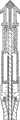
致动器的属性可以是机械的、液压的、气动的或电-机械的。图23-27示出了示例性的致动系统200的一个实施方式。如图23所示,致动系统包括搁置在切割工具的外部的PE管。切割工具可以做一切口,并且然后PE管被推动穿过该切口,直到内部(远端)凸缘位于中耳空间。该切割工具随后被收回并且PE管被留在原位置。PE管内部凸缘成形成为带有一角度,以在其穿过时帮助打开切口。整个致动器外壳被设计成搁置在引导块的工作通道内,该工作通道被插入并稳定在耳道内。The nature of the actuator can be mechanical, hydraulic, pneumatic or electro-mechanical. One embodiment of an
图23所示的某些部件也用于实现致动器系统的测距能力。在一个实施方式中,致动器系统使用被动测距技术。所谓的接触件包含切割工具和PE管,并且搁置在致动器外壳内。低力弹簧用于在接触护套上放置小的预载荷。在用户将致动器单元滑入引导块的工作通道时,接触护套与TM接触并压缩弹簧,直到引导件被牢固地搁置在引导设备中的硬停止件上。此时,接触件正触及TM,并且切割工具位于距接触件的端部的固定距离处,并且因此,该距离为距TM的固定距离。弹簧被设计成使得施加到TM的力将不引起对于患者的任何损害或不适。此时,接触件、切割工具以及PE管需要被锁定到引导件。示出于图23中的锁定件提供锁定机构。图24示出了处于未锁定状态的示例性致动器。图25示出了处于锁定状态的致动器。锁定件包含两个刀片状元件,当旋转时,两个刀片状元件切割进入接触件上的弹性体元件,在轴向方向将接触件锁定。一旦被锁定,则切割柱塞、切割工具、搭扣件以及PE管独立于接触件以及引导件移动。致动器此时准备好切割和部署。Certain components shown in Figure 23 are also used to enable the ranging capability of the actuator system. In one embodiment, the actuator system uses passive ranging techniques. The so-called contact piece contains the cutting tool and the PE pipe and rests inside the actuator housing. Low force springs are used to place a small preload on the contact sheath. As the user slides the actuator unit into the working channel of the guide block, the contact sheath comes into contact with the TM and compresses the spring until the guide is securely resting on a hard stop in the guide device. At this point, the contact is touching the TM, and the cutting tool is at a fixed distance from the end of the contact, and thus, this distance is a fixed distance from the TM. The spring is designed such that the force applied to the TM will not cause any damage or discomfort to the patient. At this point, the contacts, cutting tool and PE pipe need to be locked to the guide. The lock shown in Figure 23 provides the locking mechanism. Figure 24 shows an exemplary actuator in an unlocked state. Figure 25 shows the actuator in a locked state. The lock comprises two blade-like elements which, when rotated, cut into the elastomeric element on the contact, locking the contact in the axial direction. Once locked, the cutting plunger, cutting tool, snap and PE tube move independently of the contact and guide. The actuator is now ready to cut and deploy.
图26示出了完全部署的致动器设备,同时切割工具贴靠着在搭扣件和接触件之间产生的硬停止件。搭扣件具有开合(snap out)的两“腿”并产生锁定机构以便在切割工具被收回时搭扣件不收回。图27示出了带有在部署PE管之后被收回的切割工具的致动器设备。该搭扣件使PE管不被切割工具拉回,保留PE管正确地放置在TM切口中。此时,致动器或整个引导设备可以被安全地从耳移除。Figure 26 shows the fully deployed actuator device with the cutting tool against the hard stop created between the snap and contact. The snap has two "legs" that snap out and create a locking mechanism so that the snap does not retract when the cutting tool is retracted. Figure 27 shows the actuator device with the cutting tool retracted after deployment of the PE tube. This snap prevents the PE tube from being pulled back by the cutting tool, keeping the PE tube properly placed in the TM incision. At this point, the actuator or the entire guiding device can be safely removed from the ear.
使用套管内的电缆,运动被施加到致动器。使用了两个套管:提供锁定接触件所需的扭转运动的内部套管以及提供结构支撑的外部套管。Motion is applied to the actuator using a cable inside the bushing. Two bushings are used: an inner bushing that provides the torsional movement required to lock the contacts and an outer bushing that provides structural support.
示例性的切割工具的几何形状被展示为类似于鼓膜切开术矛状体的简单的矛状切割工具。也可以使用其它几何形状的切割工具。发现形式为鼓膜切开术矛状体的一种优选的切割工具具有非常好的切割特性,包括切割力低、切痕干净以及明显不受TM角度、TM尺寸和切割速度影响。其它类型的切割几何形状,比如脊椎穿刺针和套管针可在切割穿过膜之后产生瓣。这些瓣可能增加皮肤细胞进入中耳空间的可能性;然而,这些形式的可能的益处包括提供增加的开放区域,PE管可以通过该增加的开放区域插入,从而减少施加在鼓膜上的力量,并因此减轻患者的感觉(如图38-40示出的)。切割工具可以被致动,使得鼓膜切开术相对于鼓膜的结构特定地定向,例如被定位在径向或横向方向。An exemplary cutting tool geometry is shown as a simple spear cutting tool similar to a myringotomy spear. Cutting tools of other geometries may also be used. A preferred cutting tool in the form of a myringotomy spear was found to have very good cutting characteristics, including low cutting force, clean kerf and significant independence from TM angle, TM size and cutting speed. Other types of cutting geometries, such as spinal needles and trocars, can create flaps after cutting through the membrane. These flaps may increase the likelihood of skin cells entering the middle ear space; however, possible benefits of these forms include providing an increased open area through which a PE tube can be inserted, thereby reducing the force exerted on the tympanic membrane, and The patient's sensations are thus relieved (as shown in Figures 38-40). The cutting tool may be actuated such that the myringotomy is specifically oriented relative to the structure of the eardrum, for example positioned in a radial or transverse direction.
图38-40示出了可以使用各种不同的切割工具制作在TM中的各种鼓膜切开术/鼓膜造孔术洞的形状。图38B示出了通过使用图38A示出的皮下注射针形成在TM中的不带有瓣的弯曲洞。图39B示出了通过使用图39A示出的鼓膜切开术矛状体形成在TM中的不带有瓣的笔直洞。图40B示出了通过使用图40A示出的套管针形成于TM中的带有瓣的Y字型洞。38-40 illustrate various myringotomy/tympanostomy hole shapes that can be made in a TM using various cutting tools. Figure 38B shows a curved hole without flaps formed in the TM by using the hypodermic needle shown in Figure 38A. Figure 39B shows a straight hole without flaps formed in the TM by using the myringotomy spear shown in Figure 39A. Figure 40B shows the valved Y-shaped hole formed in the TM by using the trocar shown in Figure 40A.
示例性的驱动系统可以包括下列部件:DC电动机驱动装置;驱动两个导螺杆的减速传动装置,对于每个致动器单元各一个;将导螺杆的线性运动转换成驱动系统和致动器单元之间的运动耦合器的线性运动的连接器;AC输入电源模块以及AC-DC电源;带有控制电子设备的印刷电路板(PCB);带有合适的用户界面以及可能的安装支架以便悬挂在检查椅的后部的外壳。An exemplary drive system may include the following components: a DC motor drive; a reduction transmission driving two lead screws, one for each actuator unit; converting the linear motion of the lead screw to the drive system and actuator unit Connector for linear motion of kinematic coupler between; AC input power supply module and AC-DC power supply; printed circuit board (PCB) with control electronics; with suitable user interface and possible mounting bracket for hanging on Check the shell on the back of the chair.
可能有其它驱动系统机构,包括安装在耳外部的“头戴耳机”系统以及遥控的、手持式的、手动操作的机构的概念。Other drive system mechanisms are possible, including "headphone" systems mounted outside the ear, and remote-controlled, hand-held, manually-operated mechanism concepts.
图28-32示出了用于组合的PE管输送设备(PETDD)的致动系统的可选择的实施方式。如图28所示,该PETDD具有大致圆柱形主体,该大致圆柱形主体可以配合在引导块的工作通道内部。该PETDD可以包括包含在设备主体内的两个致动器级(actuator stage),一个用于穿入TM,而第二个用于收回针并部署PE管。通向致动器的电连接可以被制成用于穿入和收回级的线元件。可对图28的致动器使用四条线,其可以在挠性电路(flex circuit)终结。28-32 illustrate an alternative embodiment of an actuation system for a combined PE tube delivery device (PETDD). As shown in Figure 28, the PETDD has a generally cylindrical body that can fit inside the working channel of the guide block. The PETDD may include two actuator stages contained within the device body, one for threading the TM and the second for retracting the needle and deploying the PE tube. Electrical connections to the actuator can be made for threading and retracting stage wire elements. Four wires can be used with the actuator of Figure 28, which can terminate at a flex circuit.
图29示出了通过图28的PETDD的中心线的截面图。如图28示出的,该PETDD可以具有不锈钢外壳。该外壳围绕穿入致动器弹簧(pierceactuator spring)以及收回致动器弹簧(retract actuator spring)。该穿入致动器弹簧由穿入线熔断器(pierce wire fuse)保持在压缩形式。该收回致动器也由收回线熔断器(retract wire fuse)保持在压缩形式。结合图30-32描述了PETDD的操作。FIG. 29 shows a cross-sectional view through the centerline of the PETDD of FIG. 28 . As shown in Figure 28, the PETDD may have a stainless steel housing. The housing surrounds a piercing actuator spring (pierceactuator spring) and a retracting actuator spring (retract actuator spring). The piercing actuator spring is held in compressed form by a piercing wire fuse. The retract actuator is also held in compressed form by a retract wire fuse. The operation of PETDD is described in conjunction with Figures 30-32.
图30-32描述的次序显示了该设备的三个阶段。图30示出了插入准备状态,其中,该设备准备用于其刀片的插入。在此阶段,熔断器线是完整的,并且致动器弹簧正储存机械能。图31显示了穿入状态,其中,穿入熔断器线已经蒸发,并且柳叶刀已经穿入了具有横向的短距离(例如2mm冲程)的TM。如图21示出的,在此阶段,穿入和收回致动器均已经关于外壳行进了相同的短距离(例如2mm冲程)。图32显示了部署和收回阶段,其中,收回/部署熔断器已经蒸发。在此阶段,该设备的收回阶段相对于外壳和穿入阶段向后移动该短距离(例如2mm冲程),并且PE管保持处于TM中。The sequence depicted in Figures 30-32 shows the three phases of the device. Figure 30 shows an insertion readiness state in which the device is ready for insertion of its blade. At this stage, the fuse link is intact and the actuator spring is storing mechanical energy. Figure 31 shows the piercing state where the piercing fuse line has evaporated and the lancet has pierced the TM with a short lateral distance (eg 2mm stroke). As shown in Figure 21, at this stage both the threading and retracting actuators have traveled the same short distance (eg 2mm stroke) with respect to the housing. Figure 32 shows the deploy and retract phase, where the retract/deploy fuse has evaporated. At this stage, the retraction phase of the device moves back the short distance (eg 2mm stroke) relative to the housing and penetration phase, and the PE tube remains in the TM.
本发明的实施方式的某些方面涉及PE管的独特形状。图41A-C示出了各种PE管形状,包括用于经过PETDD自动插入PE管的中断的中间凸缘。Certain aspects of embodiments of the invention relate to the unique shape of the PE pipe. Figures 41A-C illustrate various PE pipe shapes including interrupted intermediate flanges for automatic insertion of PE pipe through the PETDD.
除了上面两种PETDD实施方式外,基于激光的穿入工具也可用于穿入患者耳的TM。另外,PETDD可以被设计成使得PE管的部署居中地通向耳膜开始,并且以这样的方式前进以完成侧向地通向膜,使得实现从内到外致动设备;这些益处包括使PE管部署的控制最大化,以便在居中-侧向的方向(增加安全度)而不是侧向-居中(减少安全度)推进。In addition to the above two PETDD embodiments, laser-based penetration tools can also be used to penetrate the TM in the patient's ear. In addition, the PETDD can be designed so that deployment of the PE tube begins centrally towards the eardrum and progresses in such a way to complete laterally towards the membrane that actuation of the device from the inside out is achieved; these benefits include making the PE tube Deployment control is maximized to advance in a center-to-side direction (increasing safety) rather than side-to-center (decreasing safety).
图42A-B示出了从切割工具的内部输送的PE管204A。该所谓的内部PE管被设置成压缩的以便在切割工具内输送;可使用推杆部署PE管使其离开切割工具,并且PE管的特征膨胀以使其像图42B中示出的那样锚固在TM中。该所谓的内部PE管是有优势的,因为切割工具被设置成形成受控的切口尺寸,且PE管的部署不在TM上放置多余的压力,因为当通过切割工具部署管时,TM不大可能遭受TM的撕裂、压力或拉伸。同样,如图43A-B示出的,所谓的内部PE管设置还可以和索环或T管型PE管设计一起使用。42A-B
图44A-B示出了在切割工具的外侧上输送的PE管204C。所谓的外部PE管可以具有帮助TM中的切口膨胀的特征。这些特征包括有锥度的前缘凸缘或者薄的或者柔性的内部凸缘。所谓的外部PE管可以是有优势的,因为它将使得能够形成较小的切口。另外,所谓的外部PE管较少地依靠PE管上的可部署的特征,因为对于PE管没有必要在其储存在PETDD设备的过程中像在所谓的内部PE管中那样内部压缩。另外,对于所谓的外部PE管,切割工具可以为标准的鼓膜切开术矛状体或刀片的型式。如图44A所示,推杆上的凸缘可以防止PE管的过度插入。另外,如图44C-D示出的,PE管上的凸缘可以具有切口,以允许更容易地通过以及其穿过TM的挠曲。44A-B show PE tubing 204C delivered on the outside of the cutting tool. The so-called external PE tubing can have features that help expand the incision in the TM. These features include a tapered leading edge flange or a thin or flexible inner flange. A so called external PE pipe can be advantageous as it will enable smaller incisions to be made. In addition, the so-called external PE pipe relies less on deployable features on the PE pipe, since there is no need for the PE pipe to be internally compressed during its storage in the PETDD facility as in the so-called internal PE pipe. Additionally, for so-called external PE tubing, the cutting tool can be of the standard myringotomy spear or blade type. As shown in Figure 44A, the flange on the push rod prevents over-insertion of the PE tube. Additionally, as shown in Figures 44C-D, the flange on the PE tube may have cutouts to allow for easier passage and its flexing through the TM.
本发明的实施方式的某些方面涉及用于将PETDD定位在X-Y方向的凸轮/偏心机构的使用。图37A-C示出了将PETDD定位在X-Y方向的凸轮/偏心机构的实施方式。图37A显示了PETDD 200定位在耳道10内,并且PETDD的远端定位成靠近TM 12。PETDD的此实施方式包括外壳260,该外壳260被设置成配合在耳道和/或引导块的部分中。PETDD 200经过凸轮262连接到外壳260。该外壳260可固加到适当的耳结构(例如外耳道)。凸轮262被设置成能在外壳260内转动。PETDD 200被偏心地安装到凸轮的中心线。在操作中,当PETDD 200的远(即内侧)端被固定在引导块100时,凸轮262的转动允许PETDD在X-Y方向关于TM 12上瞄准的目标的大约圆形扫掠。如图37C所示,PETDD的启用凸轮的实施方式被设置成具有以圆形方式在X-Y方向扫掠TM 12的目标,该X-Y方向实质上与TM 12的平面平行。应认识到,凸轮的后端不必位于耳道中。其可以被定位在耳的外面。例如,当有“耳罩”型稳定机构时,该凸轮可以位于耳的外面。Certain aspects of embodiments of the invention relate to the use of a cam/eccentric mechanism for positioning the PETDD in the X-Y direction. 37A-C illustrate an embodiment of a cam/eccentric mechanism to position the PETDD in the X-Y direction. Figure 37A shows the
上面描述的系统和设备可用于实践除了上面描述的手术之外的各种不同的手术。例如,引导块系统可用于提供通过工作通道吸出和抽吸的能力。另外,临床医生可能也需要使用抽吸以轻柔地朝着引导块和/或PETDD向后“拉”或操纵TM,这将保证致动器和TM之间的某距离以允许更安全的插入PE管。The systems and devices described above may be used to practice a variety of different procedures in addition to those described above. For example, a guide block system can be used to provide the ability to aspirate and aspirate through the working channel. Additionally, the clinician may also need to use suction to gently "pull" or maneuver the TM back towards the guide block and/or PETDD, which will maintain some distance between the actuator and the TM to allow for safer insertion of the PE Tube.
测距ranging
在一个示例性实施方式中,可以使用基于光的测距技术。该基于光的系统包括在PE管放置设备上的两个发光元件(比如激光器),该发光元件产生集中的光束。如图33所示,该发光元件以这样一种方式定向,以使得它们产生的射线的交点位于距PE管放置设备的预定距离处。当来自两个发光元件的射线投射到表面比如TM上时,它们产生两个可见的点。随着PE管放置设备在垂直于投射表面的方向移动,在表面上产生的点随着接近设计距离(y)而移动得更靠近一起。当达到设计距离时两点重合。可选择地,光束可以为重叠形成位于设计距离的十字准线的线。In one exemplary embodiment, light-based ranging techniques may be used. The light-based system includes two light-emitting elements (such as lasers) on the PE pipe placement device, which generate a concentrated beam of light. As shown in Figure 33, the light emitting elements are oriented in such a way that the intersection of the rays they generate is located at a predetermined distance from the PE pipe placement device. When the rays from the two light-emitting elements hit a surface such as a TM, they create two visible points. As the PE pipe placement device moves in a direction perpendicular to the projection surface, the points created on the surface move closer together as the design distance (y) is approached. When the design distance is reached, the two points coincide. Alternatively, the light beams may be lines overlapping to form crosshairs at a designed distance.
图34A-B示出了可选择的用于测距的技术,其说明了一种基于接触开关的测距技术(contact-switch-based range finding technique)。这些接触开关元件移位并完成电路-类似于向端子发送电压的安全开关。图34A显示了依靠在电路闭合之前的固定收回距离的基于接触开关的测距技术。图34B显示了依靠在电路闭合之前的非固定收回距离的基于接触开关的测距技术。在此方案中,使用传感器确定量程内的接触位置和量程外的接触位置之间的接触。Alternative techniques for ranging are shown in Figures 34A-B, which illustrate a contact-switch-based range finding technique. These contact switching elements shift and complete the circuit - similar to a safety switch that sends voltage to the terminals. Figure 34A shows a contact switch based ranging technique that relies on a fixed retraction distance before circuit closure. Figure 34B shows a contact switch based ranging technique that relies on a non-fixed retraction distance before circuit closure. In this scheme, a sensor is used to determine contact between an in-range contact location and an out-of-range contact location.
上文描述的测距实施方式用于对于放置PE管和/或鼓膜切开术建立在TM上的X-Y瞄准位置。为了PE管输送和/或鼓膜切开术的安全和可靠度,测距实施方式还用于建立距TM的在某量程内的Z距离。图54A-B示出了该X-Y瞄准位置和Z距离。除上文描述的测距实施方式外,还可以使用接下来的测距实施方式。The ranging implementation described above is used to establish an X-Y aiming position on the TM for PE tube placement and/or myringotomy. The ranging implementation is also used to establish a Z-distance to within a certain range from the TM for safety and reliability of PE tube delivery and/or myringotomy. Figures 54A-B illustrate the X-Y aiming position and Z distance. In addition to the ranging implementations described above, the following ranging implementations may also be used.
图55A-B中描述的附加的第一实施方式涉及安装在引导块远端的细头发状元件的使用。当使用此实施方式时,通过使用内窥镜观察TM上的头发状元件或胡须状物的接触和挠曲,可以完成瞄准和测距。具体地,瞄准通过观察胡须状物在TM上的接触点实现,而测距通过观察已知长度的胡须状物的挠曲实现。An additional first embodiment described in Figures 55A-B involves the use of thin hair-like elements mounted at the distal end of the guide block. When using this embodiment, aiming and ranging can be accomplished by using an endoscope to observe the contact and deflection of the hair-like elements or whiskers on the TM. Specifically, aiming is achieved by observing the contact point of the whisker on the TM, while ranging is achieved by observing the deflection of a whisker of known length.
图56A-B中描述的附加的第二个实施方式涉及非接触激光瞄准的使用。如图56A-B所示,两个激光束成角度,以便当它们距TM成某距离时重合成斑点或十字准线。如图56B所示,该光束可以投射成斑点形状(A)。图56B示出了光束斑点在不同量程的瞄准表面上看起来是怎样的。当目标量程刚好正确时,两光束重合,并且当目标距离太近或太远时,两光束看起来像两个斑点。可选择地,这些光束看起来像能形成十字准线的线。例如,当目标量程刚好正确时,两光束重合形成十字准线,并且当瞄准距离太近或太远时,两光束看起来像两条分开的线。此基于激光的实施方式的一个优势在于其不接触TM,并因此可以用来在麻醉前和麻醉后测距和瞄准。An additional second embodiment described in Figures 56A-B involves the use of non-contact laser targeting. As shown in Figures 56A-B, the two laser beams are angled so that they coincide into a spot or crosshair when they are some distance from the TM. As shown in Figure 56B, the beam can be projected into a spot shape (A). Figure 56B shows how the beam spot looks on different ranges of aiming surfaces. When the target range is just right, the two beams coincide, and when the target is too close or too far away, the two beams look like two spots. Optionally, the beams look like lines that form crosshairs. For example, when the target range is just right, the two beams coincide to form a crosshair, and when the aiming distance is too close or too far, the two beams appear as two separate lines. One advantage of this laser-based embodiment is that it does not touch the TM and thus can be used for ranging and targeting both pre- and post-anesthesia.
图57A-B示出的附加的第三实施方式涉及非接触的光学瞄准方法的使用。此光学的和非接触的技术可以被构造进入内窥镜中,从而消除对于分离的部件的需要。在一个实施方式中,该光学方案可以使用固定的焦距配置。在此配置中,内窥镜的焦距对应于目标量程,以使当内窥镜屏幕上的图像看起来已聚焦时,那时目标位于量程内。在另一个实施方式中,光学方案可以使用分度线和点。在此配置中,光束从引导块的端部投射。内窥镜被设置成具有带有圆圈的分度线。当点或光束的大小与分度线上的圆圈相同时,目标位于量程内。当点或光束小于分度线上的圆圈时,目标太近,而当点或光束大于分度线上的圆圈时,目标太远。An additional third embodiment shown in Figures 57A-B involves the use of a non-contact optical aiming method. This optical and non-contact technology can be built into endoscopes, eliminating the need for separate components. In one embodiment, the optical scheme may use a fixed focal length configuration. In this configuration, the focal length of the endoscope corresponds to the target range such that when the image on the endoscope screen appears to be in focus, then the target is within range. In another embodiment, the optical scheme may use reticles and dots. In this configuration, the beam is projected from the end of the guide block. The endoscope is configured to have a graduated line with a circle. When the spot or beam is the same size as the circle on the reticle, the target is within range. When the point or beam is smaller than the circle on the reticle, the target is too close, and when the point or beam is larger than the circle on the reticle, the target is too far away.
与图像构造有关,耦合器可用于将两个内窥镜连接到单个摄像机,同时从两个视野提供图像。可选择地,视频分裂器(video splitter)可用于从两个摄像机向单个监视器发送图像。因为引导块和TM之间的空间将被流体填充,所以也可使用超声形成图像。另外,例如在放置PE管时,超声可用于驱动遍布于TM上的麻醉剂并随后形成组织区域的图像。Related to image construction, couplers can be used to connect two endoscopes to a single camera, providing images from both fields of view simultaneously. Optionally, a video splitter can be used to send images from both cameras to a single monitor. Ultrasound can also be used to form images since the space between the guide mass and the TM will be filled with fluid. Additionally, ultrasound can be used to drive the anesthetic over the TM and subsequently image the tissue area, such as when placing a PE tube.
另外,测距还可以通过超声、雷达型技术完成。这可以经过将介质送入空间而被促进以允许超声/雷达方法。该介质可以减少能量要求。In addition, ranging can also be done by ultrasonic, radar type technology. This can be facilitated by sending media into the space to allow ultrasound/radar methods. This medium can reduce energy requirements.
图35A-B示出了依据本发明的一个实施方式的具有检耳镜、引导管稳定器和测距仪的组合特征的手持式设备500。如图35A所示,该设备500包括把手部分502,该把手部分502形成设备的主体的一部分。该设备500还包括可用于致动检耳镜、激光测距仪和/或模塑材料或稳定材料的注射的触发器504。设备500可包括尺寸制定成接纳模塑材料的一部分,在一个实施方式中,这部分可以为两部分聚硅酮模塑材料506。设备500的尺寸制定成保持引导管508或上文描述的一个或多个管。引导管的远端包括屏障材料510。设备500还保持用于耳道的内部空间的直接显像的光学器件512。该设备500还保持用于测量量程或测量深度用途的激光光学器件516。图35B示出了激光测距仪516的进一步的细节。激光530被引向分裂器531,分裂器531随后将分裂的激光导向镜532,镜532随后将激光导向焦点534。与测距仪516的距离可设定为穿过棱镜531的单激光束,棱镜531分裂光束并将其聚焦在焦点534。在操作中,在设备500之后已经被使用并从耳道被移除后,引导管508和屏障材料510被设置成在模塑材料506已经被输送之后留下来。设备500还可以帮助保持引导管508或一个或多个管在模塑材料的注射之前在原位置对准。Figures 35A-B illustrate a hand-held
除上文的描述以外,接下来的可选择的概念也在本发明构想的实施方式内。例如,除上文描述的电动机和螺杆传动装置以及预加载的弹簧实施方式以外,驱动系统可以为气动系统、基于简单螺线管的系统;或基于伺服螺线管的系统。例如,驱动系统和PETDD之间的耦合可经由柔性杆或控制线。例如,测距仪可以使用电容接触感应器或应变接触感应器。且例如,切割工具可以为实心刀片、中空柳叶刀、螺钉、剪刀或激光。In addition to the above description, the following optional concepts are also within the contemplated embodiments of the present invention. For example, in addition to the electric motor and screw drive and preloaded spring implementations described above, the drive system could be a pneumatic system, a simple solenoid based system; or a servo solenoid based system. For example, the coupling between the drive system and the PETDD could be via flexible rods or control wires. For example, range finders may use capacitive touch sensors or strain touch sensors. And for example, the cutting tool may be a solid blade, a hollow lancet, a screw, scissors or a laser.
如本领域技术人员应理解的,本发明可以按其它具体形式实现而不背离于其基本特性。这些其它实施方式预期包含在本发明的范围中,而本发明的范围在接下来的权利要求中被阐明。As will be understood by those skilled in the art, the present invention may be embodied in other specific forms without departing from its essential characteristics. These other embodiments are intended to be included within the scope of the invention as set forth in the following claims.
Claims (50)
Applications Claiming Priority (3)
| Application Number | Priority Date | Filing Date | Title |
|---|---|---|---|
| US91290207P | 2007-04-19 | 2007-04-19 | |
| US60/912,902 | 2007-04-19 | ||
| PCT/US2008/060779WO2008131195A2 (en) | 2007-04-19 | 2008-04-18 | System and method for the simultaneous bilateral treatment of target tissues within the ears |
Related Child Applications (1)
| Application Number | Title | Priority Date | Filing Date |
|---|---|---|---|
| CN201310047126.XADivisionCN103202744B (en) | 2007-04-19 | 2008-04-18 | System for the both sides synchronous therapeutic of in ear destination organization |
Publications (2)
| Publication Number | Publication Date |
|---|---|
| CN101795646Atrue CN101795646A (en) | 2010-08-04 |
| CN101795646B CN101795646B (en) | 2013-03-27 |
Family
ID=39872990
Family Applications (2)
| Application Number | Title | Priority Date | Filing Date |
|---|---|---|---|
| CN201310047126.XAExpired - Fee RelatedCN103202744B (en) | 2007-04-19 | 2008-04-18 | System for the both sides synchronous therapeutic of in ear destination organization |
| CN2008800208619AExpired - Fee RelatedCN101795646B (en) | 2007-04-19 | 2008-04-18 | System for Bilateral Simultaneous Treatment of Target Tissues in the Ear |
Family Applications Before (1)
| Application Number | Title | Priority Date | Filing Date |
|---|---|---|---|
| CN201310047126.XAExpired - Fee RelatedCN103202744B (en) | 2007-04-19 | 2008-04-18 | System for the both sides synchronous therapeutic of in ear destination organization |
Country Status (7)
| Country | Link |
|---|---|
| US (11) | US8249700B2 (en) |
| EP (2) | EP3300707A1 (en) |
| JP (1) | JP5595905B2 (en) |
| CN (2) | CN103202744B (en) |
| AU (1) | AU2008242735B2 (en) |
| CA (3) | CA3002994A1 (en) |
| WO (1) | WO2008131195A2 (en) |
Cited By (7)
| Publication number | Priority date | Publication date | Assignee | Title |
|---|---|---|---|---|
| CN102743812A (en)* | 2012-07-18 | 2012-10-24 | 孙晓卫 | Fixed eardrum tube placing device |
| CN103826581A (en)* | 2011-07-25 | 2014-05-28 | 阿克拉伦特公司 | Personalizable system and method for anesthetizing tympanic membrane |
| CN104244878A (en)* | 2012-04-10 | 2014-12-24 | 阿克拉伦特公司 | Tympanic membrane pressure equalization tube |
| CN104287952A (en)* | 2013-07-16 | 2015-01-21 | 北京中卫神农慢性病医学研究院有限公司 | Targeting information ear therapeutic device |
| CN105833417A (en)* | 2016-03-15 | 2016-08-10 | 西安医学院第二附属医院 | Head-wearing drug delivery device used for treating ear disease |
| CN111386095A (en)* | 2017-09-26 | 2020-07-07 | 延世大学校原州产学协力团 | Otitis media treatment device |
| CN114010924A (en)* | 2021-11-08 | 2022-02-08 | 中国人民解放军总医院第三医学中心 | ear canal drug injection device |
Families Citing this family (167)
| Publication number | Priority date | Publication date | Assignee | Title |
|---|---|---|---|---|
| DE10105592A1 (en) | 2001-02-06 | 2002-08-08 | Achim Goepferich | Placeholder for drug release in the frontal sinus |
| US6770080B2 (en) | 2001-04-26 | 2004-08-03 | Fenestra Medical, Inc. | Mechanically registered videoscopic myringotomy/tympanostomy tube placement system |
| US8317816B2 (en) | 2002-09-30 | 2012-11-27 | Acclarent, Inc. | Balloon catheters and methods for treating paranasal sinuses |
| EP3103422A1 (en)* | 2003-03-14 | 2016-12-14 | Intersect ENT, Inc. | Sinus delivery of sustained release therapeutics |
| US8435285B2 (en)* | 2003-11-25 | 2013-05-07 | Boston Scientific Scimed, Inc. | Composite stent with inner and outer stent elements and method of using the same |
| US7351246B2 (en)* | 2004-01-20 | 2008-04-01 | Epley John M | Minimally invasive, sustained, intra-tympanic drug delivery system |
| US7462175B2 (en) | 2004-04-21 | 2008-12-09 | Acclarent, Inc. | Devices, systems and methods for treating disorders of the ear, nose and throat |
| US9554691B2 (en) | 2004-04-21 | 2017-01-31 | Acclarent, Inc. | Endoscopic methods and devices for transnasal procedures |
| US7803150B2 (en)* | 2004-04-21 | 2010-09-28 | Acclarent, Inc. | Devices, systems and methods useable for treating sinusitis |
| US7419497B2 (en) | 2004-04-21 | 2008-09-02 | Acclarent, Inc. | Methods for treating ethmoid disease |
| US8894614B2 (en) | 2004-04-21 | 2014-11-25 | Acclarent, Inc. | Devices, systems and methods useable for treating frontal sinusitis |
| US20190314620A1 (en) | 2004-04-21 | 2019-10-17 | Acclarent, Inc. | Apparatus and methods for dilating and modifying ostia of paranasal sinuses and other intranasal or paranasal structures |
| US9399121B2 (en) | 2004-04-21 | 2016-07-26 | Acclarent, Inc. | Systems and methods for transnasal dilation of passageways in the ear, nose or throat |
| US8702626B1 (en) | 2004-04-21 | 2014-04-22 | Acclarent, Inc. | Guidewires for performing image guided procedures |
| US20070208252A1 (en) | 2004-04-21 | 2007-09-06 | Acclarent, Inc. | Systems and methods for performing image guided procedures within the ear, nose, throat and paranasal sinuses |
| US7654997B2 (en) | 2004-04-21 | 2010-02-02 | Acclarent, Inc. | Devices, systems and methods for diagnosing and treating sinusitus and other disorders of the ears, nose and/or throat |
| US9089258B2 (en) | 2004-04-21 | 2015-07-28 | Acclarent, Inc. | Endoscopic methods and devices for transnasal procedures |
| US8764729B2 (en) | 2004-04-21 | 2014-07-01 | Acclarent, Inc. | Frontal sinus spacer |
| US8932276B1 (en) | 2004-04-21 | 2015-01-13 | Acclarent, Inc. | Shapeable guide catheters and related methods |
| US9351750B2 (en) | 2004-04-21 | 2016-05-31 | Acclarent, Inc. | Devices and methods for treating maxillary sinus disease |
| US7559925B2 (en) | 2006-09-15 | 2009-07-14 | Acclarent Inc. | Methods and devices for facilitating visualization in a surgical environment |
| US20070167682A1 (en) | 2004-04-21 | 2007-07-19 | Acclarent, Inc. | Endoscopic methods and devices for transnasal procedures |
| US8747389B2 (en) | 2004-04-21 | 2014-06-10 | Acclarent, Inc. | Systems for treating disorders of the ear, nose and throat |
| US10188413B1 (en) | 2004-04-21 | 2019-01-29 | Acclarent, Inc. | Deflectable guide catheters and related methods |
| US20060063973A1 (en) | 2004-04-21 | 2006-03-23 | Acclarent, Inc. | Methods and apparatus for treating disorders of the ear, nose and throat |
| US9101384B2 (en) | 2004-04-21 | 2015-08-11 | Acclarent, Inc. | Devices, systems and methods for diagnosing and treating sinusitis and other disorders of the ears, Nose and/or throat |
| US20060004323A1 (en) | 2004-04-21 | 2006-01-05 | Exploramed Nc1, Inc. | Apparatus and methods for dilating and modifying ostia of paranasal sinuses and other intranasal or paranasal structures |
| US8864787B2 (en) | 2004-04-21 | 2014-10-21 | Acclarent, Inc. | Ethmoidotomy system and implantable spacer devices having therapeutic substance delivery capability for treatment of paranasal sinusitis |
| US8401212B2 (en) | 2007-10-12 | 2013-03-19 | Earlens Corporation | Multifunction system and method for integrated hearing and communication with noise cancellation and feedback management |
| JP5247428B2 (en) | 2005-04-04 | 2013-07-24 | インターセクト エント, インコーポレイテッド | Apparatus and method for treating sinus symptoms |
| US8951225B2 (en) | 2005-06-10 | 2015-02-10 | Acclarent, Inc. | Catheters with non-removable guide members useable for treatment of sinusitis |
| US8114113B2 (en) | 2005-09-23 | 2012-02-14 | Acclarent, Inc. | Multi-conduit balloon catheter |
| US8535707B2 (en) | 2006-07-10 | 2013-09-17 | Intersect Ent, Inc. | Devices and methods for delivering active agents to the osteomeatal complex |
| US9820688B2 (en) | 2006-09-15 | 2017-11-21 | Acclarent, Inc. | Sinus illumination lightwire device |
| US8439687B1 (en) | 2006-12-29 | 2013-05-14 | Acclarent, Inc. | Apparatus and method for simulated insertion and positioning of guidewares and other interventional devices |
| US8249700B2 (en) | 2007-04-19 | 2012-08-21 | Acclarent, Inc. | System and method for the simultaneous bilateral integrated tympanic drug delivery and guided treatment of target tissues within the ears |
| US8118757B2 (en) | 2007-04-30 | 2012-02-21 | Acclarent, Inc. | Methods and devices for ostium measurement |
| US8485199B2 (en) | 2007-05-08 | 2013-07-16 | Acclarent, Inc. | Methods and devices for protecting nasal turbinate during surgery |
| EP3791826B1 (en) | 2007-12-18 | 2025-01-29 | Intersect ENT, Inc. | Self-expanding devices |
| US10206821B2 (en) | 2007-12-20 | 2019-02-19 | Acclarent, Inc. | Eustachian tube dilation balloon with ventilation path |
| US8192420B2 (en) | 2007-12-20 | 2012-06-05 | Acclarent, Inc. | Iontophoresis methods |
| KR101497755B1 (en) | 2008-02-20 | 2015-03-02 | 프리셉티스 메디칼, 엘엘씨 | Ventilation device and insertion system therefor |
| US8182432B2 (en) | 2008-03-10 | 2012-05-22 | Acclarent, Inc. | Corewire design and construction for medical devices |
| US20090296980A1 (en)* | 2008-06-02 | 2009-12-03 | Steven Yi | System and Method for Producing a Geometric Model of the Auditory Canal |
| RU2500337C2 (en) | 2008-07-30 | 2013-12-10 | Аккларент, Инк. | Device and methods of identifying orifice of paranasal sinus |
| US8452392B2 (en)* | 2008-07-31 | 2013-05-28 | Acclarent, Inc. | Systems and methods for anesthetizing ear tissue |
| US8840602B2 (en)* | 2008-07-31 | 2014-09-23 | Acclarent, Inc. | Systems and methods for anesthetizing ear tissue |
| AU2009276505B2 (en) | 2008-08-01 | 2015-04-23 | Intersect Ent, Inc. | Methods and devices for crimping self-expanding devices |
| US8512715B2 (en)* | 2008-08-14 | 2013-08-20 | The Cleveland Clinic Foundation | Apparatus and method for treating a neuromuscular defect |
| WO2010025299A2 (en)* | 2008-08-27 | 2010-03-04 | Melder Patrick C | Nasal ventilation system and method of using same |
| US8945142B2 (en) | 2008-08-27 | 2015-02-03 | Cook Medical Technologies Llc | Delivery system for implanting nasal ventilation tube |
| BRPI0919195A2 (en) | 2008-09-18 | 2019-09-24 | Acclarent Inc | Methods and Apparatus for the Treatment of Ear, Nose, and Throat Disorders |
| US20100331761A1 (en)* | 2009-01-21 | 2010-12-30 | The Cleveland Clinic Foundation | Apparatus and Method for Dermatological Wound Healing |
| US9078783B2 (en) | 2008-12-24 | 2015-07-14 | Acclarent, Inc. | Silent effusion removal |
| US8435290B2 (en)* | 2009-03-31 | 2013-05-07 | Acclarent, Inc. | System and method for treatment of non-ventilating middle ear by providing a gas pathway through the nasopharynx |
| US7978742B1 (en) | 2010-03-24 | 2011-07-12 | Corning Incorporated | Methods for operating diode lasers |
| EP2754463B1 (en) | 2009-05-15 | 2016-06-22 | Intersect ENT, Inc. | Expandable devices |
| WO2011008987A2 (en) | 2009-07-15 | 2011-01-20 | Regents Of The University Of Minnesota | Treatment and placement device for sinusitis applications |
| US9770366B2 (en) | 2009-07-15 | 2017-09-26 | Tusker Medical, Inc. | Tympanic membrane pressure equalization tube delivery system |
| US9539146B2 (en) | 2009-07-15 | 2017-01-10 | Tusker Medical, Inc. | Trigger assembly for tympanostomy tube delivery device |
| EP2453855B1 (en)* | 2009-07-15 | 2013-06-26 | Acclarent, Inc. | Tympanostomy tube delivery system |
| CN103037934A (en) | 2010-03-15 | 2013-04-10 | 安特提米派尼克有限公司 | Device and method for drug delivery into the tympanic cavity with a sliding booster |
| BR112012028015A2 (en)* | 2010-05-02 | 2017-03-28 | Lake Biosciences Llc | apparatus and method |
| US9272157B2 (en) | 2010-05-02 | 2016-03-01 | Nervive, Inc. | Modulating function of neural structures near the ear |
| USD640374S1 (en) | 2010-07-15 | 2011-06-21 | Acclarent, Inc. | Tube delivery device |
| US9155492B2 (en) | 2010-09-24 | 2015-10-13 | Acclarent, Inc. | Sinus illumination lightwire device |
| DE102010047009B4 (en)* | 2010-09-30 | 2018-12-06 | Carl Zeiss Meditec Ag | Control device for an ophthalmic surgical system |
| EP2656639B1 (en) | 2010-12-20 | 2020-05-13 | Earlens Corporation | Anatomically customized ear canal hearing apparatus |
| WO2012094666A1 (en) | 2011-01-07 | 2012-07-12 | Preceptis Medical, Inc. | Stabilization system and aspiration device with protected cutting edge |
| DK2683331T3 (en)* | 2011-03-08 | 2015-04-07 | Mor Research Applic Ltd | Device for repairing a eardrum |
| CA2841160C (en)* | 2011-07-08 | 2017-09-26 | The Cleveland Clinic Foundation | System and method for wound healing |
| CA2848730A1 (en)* | 2011-09-15 | 2013-03-21 | Yoseph Yaacobi | Systems and methods for treating ear disorders |
| WO2013113022A1 (en)* | 2012-01-29 | 2013-08-01 | Entra Tympanic, Llc | Device and method for the insertion and removal of tympanostomy tubes |
| US9212534B2 (en) | 2012-03-09 | 2015-12-15 | Halliburton Energy Services, Inc. | Plugging and abandoning a well using a set-delayed cement composition comprising pumice |
| US9534165B2 (en) | 2012-03-09 | 2017-01-03 | Halliburton Energy Services, Inc. | Settable compositions and methods of use |
| USD707822S1 (en) | 2012-04-10 | 2014-06-24 | Acclarent, Inc. | Tympanic membrane pressure equalization tube |
| US20130310805A1 (en)* | 2012-05-21 | 2013-11-21 | Otitopic Inc. | Delivery of substances to the external auditory canal and nasal cavity |
| US9364648B2 (en) | 2012-05-30 | 2016-06-14 | Tusker Medical, Inc. | Adhesive earplugs useful for sealing the ear canal |
| US9370448B2 (en) | 2012-06-15 | 2016-06-21 | Preceptis Medical, Inc. | Insertion system for deploying a ventilation device |
| US11213431B2 (en) | 2012-07-05 | 2022-01-04 | Ear Tech, LLC | Nitinol tympanostomy tube |
| US10687982B2 (en)* | 2012-07-05 | 2020-06-23 | Domestic Legacy Limited Partnership | One-step tympanostomy tube and method for inserting same |
| SG11201501528PA (en) | 2012-09-12 | 2015-03-30 | Univ Singapore | Device for inserting an implant and method of using the same |
| US8795290B2 (en) | 2012-10-05 | 2014-08-05 | Gyrus Acmi, Inc. | Ear pressure equalizing tube and insertion device |
| CN104797220B (en)* | 2012-11-15 | 2018-02-13 | 科克理工学院 | Eardrum pipe and insertion apparatus |
| US9204963B2 (en) | 2013-03-13 | 2015-12-08 | Gyrus Acmi, Inc. | Stabilizing implant with expandable segments |
| US9320652B2 (en) | 2013-03-14 | 2016-04-26 | Tusker Medical, Inc. | Features to improve and sense tympanic membrane apposition by tympanostomy tube delivery instrument |
| AU2014236729B2 (en) | 2013-03-14 | 2018-11-22 | Intersect Ent, Inc. | Systems, devices, and method for treating a sinus condition |
| US9681891B2 (en) | 2013-03-14 | 2017-06-20 | Tusker Medical, Inc. | Tympanostomy tube delivery device with cutting dilator |
| US10130808B2 (en) | 2013-03-14 | 2018-11-20 | Tusker Medical, Inc. | System and method for providing iontophoresis at tympanic membrane |
| US9433437B2 (en) | 2013-03-15 | 2016-09-06 | Acclarent, Inc. | Apparatus and method for treatment of ethmoid sinusitis |
| US9629684B2 (en) | 2013-03-15 | 2017-04-25 | Acclarent, Inc. | Apparatus and method for treatment of ethmoid sinusitis |
| US10065047B2 (en) | 2013-05-20 | 2018-09-04 | Nervive, Inc. | Coordinating emergency treatment of cardiac dysfunction and non-cardiac neural dysfunction |
| US12396892B2 (en) | 2013-06-28 | 2025-08-26 | Nocira, Llc | External ear canal pressure regulation device |
| US10251790B2 (en) | 2013-06-28 | 2019-04-09 | Nocira, Llc | Method for external ear canal pressure regulation to alleviate disorder symptoms |
| US9039639B2 (en) | 2013-06-28 | 2015-05-26 | Gbs Ventures Llc | External ear canal pressure regulation system |
| US9510743B2 (en) | 2013-12-17 | 2016-12-06 | Biovision Technologies, Llc | Stabilized surgical device for performing a sphenopalatine ganglion block procedure |
| US9694163B2 (en) | 2013-12-17 | 2017-07-04 | Biovision Technologies, Llc | Surgical device for performing a sphenopalatine ganglion block procedure |
| US10016580B2 (en) | 2013-12-17 | 2018-07-10 | Biovision Technologies, Llc | Methods for treating sinus diseases |
| US9516995B2 (en) | 2013-12-17 | 2016-12-13 | Biovision Technologies, Llc | Surgical device for performing a sphenopalatine ganglion block procedure |
| EP2898920B1 (en) | 2014-01-24 | 2018-06-06 | Cook Medical Technologies LLC | Articulating balloon catheter |
| GB201405414D0 (en)* | 2014-03-26 | 2014-05-07 | Northwood Medical Innovations Ltd | Surgical introducer |
| US9510976B2 (en) | 2014-04-29 | 2016-12-06 | Abbott Cardiovascular Systems Inc. | Devices and methods for treatment of the Eustachian tube and sinus cavity |
| WO2015179207A1 (en)* | 2014-05-19 | 2015-11-26 | Cain Frank J | Biomedical aural delivery systems and methods |
| DK3169396T3 (en) | 2014-07-14 | 2021-06-28 | Earlens Corp | Sliding bias and peak limitation for optical hearing aids |
| US20160038341A1 (en) | 2014-08-08 | 2016-02-11 | Acclarent, Inc. | Tympanostomy tube delivery device with elastomeric brake |
| US10195086B2 (en) | 2014-08-11 | 2019-02-05 | Tusker Medical, Inc. | Tympanostomy tube delivery device with rotatable |
| US9833360B2 (en) | 2014-08-12 | 2017-12-05 | Tusker Medical, Inc. | Tympanostomy tube delivery device with replaceable shaft portion |
| US9833359B2 (en) | 2014-08-12 | 2017-12-05 | Tusker Medical, Inc. | Tympanostomy tube delivery device with cutter force clutch |
| WO2016057357A1 (en)* | 2014-10-06 | 2016-04-14 | Med-El Elektromedizinische Geraete Gmbh | Template for bilateral symmetric stimulator fixation/implantation |
| US9924276B2 (en) | 2014-11-26 | 2018-03-20 | Earlens Corporation | Adjustable venting for hearing instruments |
| USD772406S1 (en) | 2014-12-16 | 2016-11-22 | Biovision Technologies, Llc | Surgical device |
| JP2018504209A (en) | 2015-01-22 | 2018-02-15 | インターセクト エント, インコーポレイテッド | Drug coated balloon |
| WO2016154148A1 (en)* | 2015-03-20 | 2016-09-29 | Massachusetts Eye And Ear Infirmary | Artificial tympanic membrane devices and uses |
| US20180146839A1 (en)* | 2015-06-24 | 2018-05-31 | The Regents Of The University Of Colorado, A Body Corporate | Multi-use scope |
| US11717140B2 (en) | 2015-06-24 | 2023-08-08 | The Regents Of The University Of Colorado, A Body Corporate | Multi-use endoscope with integrated device-patient monitoring and patient-provider positioning and disassociation system |
| EP3313330A4 (en) | 2015-06-29 | 2019-03-20 | 480 Biomedical, Inc. | SUPPORT LOADING AND DISTRIBUTION SYSTEMS |
| US10232082B2 (en) | 2015-06-29 | 2019-03-19 | 480 Biomedical, Inc. | Implantable scaffolds for treatment of sinusitis |
| WO2017004268A1 (en) | 2015-06-29 | 2017-01-05 | 480 Biomedical, Inc. | Implantable scaffolds for treatment of sinusitis |
| US10016304B2 (en)* | 2015-07-16 | 2018-07-10 | Tusker Medical, Inc. | Earplug assembly for iontophoresis system |
| WO2017029716A1 (en)* | 2015-08-19 | 2017-02-23 | 佐藤製薬株式会社 | Syringe for tympanic injection |
| US10354558B2 (en) | 2015-08-27 | 2019-07-16 | Tusker Medical, Inc. | System and method for training use of pressure equalization tube delivery instrument |
| EP3349703A4 (en) | 2015-09-17 | 2019-07-31 | Tymcure Ltd | TYMPANOPLASTY STAMP APPLICATOR |
| DK3888564T3 (en)* | 2015-10-02 | 2025-07-14 | Earlens Corp | DEVICE FOR CUSTOMIZED DELIVERY OF MEDICINE IN THE EAR CANAL |
| US10463245B2 (en)* | 2015-12-21 | 2019-11-05 | Snug Harbor Orthopedics, LLC | Method of using cannula for surgical procedure |
| US10178483B2 (en) | 2015-12-30 | 2019-01-08 | Earlens Corporation | Light based hearing systems, apparatus, and methods |
| US11350226B2 (en) | 2015-12-30 | 2022-05-31 | Earlens Corporation | Charging protocol for rechargeable hearing systems |
| US10973664B2 (en) | 2015-12-30 | 2021-04-13 | Lyra Therapeutics, Inc. | Scaffold loading and delivery systems |
| US10760566B2 (en) | 2016-07-22 | 2020-09-01 | Nocira, Llc | Magnetically driven pressure generator |
| AU2017325700A1 (en)* | 2016-09-16 | 2019-04-11 | Massachusetts Eye And Ear Infirmary | Ear canal grafts |
| US20180093021A1 (en)* | 2016-10-02 | 2018-04-05 | Sandeep Sood | Endoscope handle with a rigid surgical suction for endoscopic micro-neurosurgery of the brain |
| WO2018093733A1 (en) | 2016-11-15 | 2018-05-24 | Earlens Corporation | Improved impression procedure |
| IT201600128780A1 (en)* | 2016-12-20 | 2018-06-20 | Techpol S R L | HYGIENIC STICARD FOR PERSONAL CARE, IN PARTICULAR FOR EARS OF THE EAR |
| CN106730182B (en)* | 2016-12-27 | 2019-07-05 | 中国人民解放军第四军医大学 | A kind of ear-nose-throat department multifunctional spraying medicine device |
| US10195376B2 (en)* | 2017-01-03 | 2019-02-05 | Alex Nyirucz | Device and method for administration of compositions to the eustachian tube |
| EP3576835B1 (en)* | 2017-02-02 | 2023-08-02 | Flow Neuroscience AB | Headset for transcranial direct-current stimulation, tdcs, and a system comprising the headset |
| EP4424293A3 (en) | 2017-02-27 | 2024-11-27 | Nocira, LLC | Ear pumps |
| US10201639B2 (en) | 2017-05-01 | 2019-02-12 | 480 Biomedical, Inc. | Drug-eluting medical implants |
| KR102097073B1 (en)* | 2017-07-21 | 2020-04-03 | 심민보 | Tip for injecting to an eardrum |
| US11730894B2 (en)* | 2017-07-21 | 2023-08-22 | Min Bo SHIM | Tip for intra-tympanic injection |
| KR101932597B1 (en) | 2017-08-24 | 2018-12-27 | (주) 엠아이원 | Sudden sensory neural hearing loss examination endoscope apparatus for aquiring microcirculation image |
| JP7471223B2 (en)* | 2018-01-16 | 2024-04-19 | タスカー メディカル,インコーポレイテッド | EARSET ASSEMBLY FOR PROVIDING IONTOPHORESIS INCLUDES VALVE - Patent application |
| CN111511265A (en) | 2018-01-16 | 2020-08-07 | 塔斯克医药股份有限公司 | Visualization device and method for otology procedure |
| CN111542288B (en)* | 2018-02-02 | 2023-08-08 | 塔斯克医药股份有限公司 | Systems, devices and methods for delivering and delivering therapeutic substances to the middle ear |
| WO2019157310A1 (en)* | 2018-02-08 | 2019-08-15 | Ear Tech, LLC | Nitinol tympanostomy tube |
| US10736783B1 (en)* | 2018-02-17 | 2020-08-11 | Thomas Paul Cogley | Fluid ear medication dispenser system |
| WO2019173470A1 (en) | 2018-03-07 | 2019-09-12 | Earlens Corporation | Contact hearing device and retention structure materials |
| CN112188877B (en)* | 2018-03-20 | 2024-11-01 | 哈佛学院院长及董事 | Tympanostomy tube or subannular ventilation tube and other medical and fluid tube designs |
| WO2019199680A1 (en) | 2018-04-09 | 2019-10-17 | Earlens Corporation | Dynamic filter |
| EP3810049A4 (en) | 2018-06-22 | 2022-03-23 | Nocira, LLC | Systems and methods for treating neurological disorders |
| WO2020005910A1 (en) | 2018-06-28 | 2020-01-02 | Sandler Scientific, Llc | Sino-nasal rinse delivery device with agitation, flow-control and integrated medication management system |
| WO2020068899A1 (en)* | 2018-09-25 | 2020-04-02 | Yoojeong Kim | Multimodal endoscope and methods of use |
| CN109276799B (en)* | 2018-11-27 | 2021-02-09 | 谢欣欣 | Otology powder hybrid medicine spraying device |
| US12138436B2 (en)* | 2019-02-25 | 2024-11-12 | Spiral Therapeutics Inc. | Intratympanic injector devices and needles for delivery of drugs and methods of use |
| US12390098B2 (en) | 2019-07-17 | 2025-08-19 | Tusker Medical, Inc. | Systems, devices, and methods for visualization during medical procedures |
| US12403291B2 (en) | 2019-08-30 | 2025-09-02 | Intersect Ent, Inc. | Submucosal bioresorbable drug eluting platform |
| US12390370B2 (en) | 2019-11-01 | 2025-08-19 | Aventamed Designated Activity Company | Tympanostomy tube |
| AU2021209675A1 (en)* | 2020-01-24 | 2022-08-25 | Spiral Therapeutics Inc. | Visualization devices, systems, and methods for otology and other uses |
| NL2025530B1 (en)* | 2020-05-08 | 2021-11-23 | Stichting Het Nederlands Kanker Inst Antoni Van Leeuwenhoek Ziekenhuis | Fluid injection device |
| GB202020301D0 (en)* | 2020-12-21 | 2021-02-03 | Ucl Business Ltd | A system for positioning a medical tool |
| WO2022264094A1 (en)* | 2021-06-18 | 2022-12-22 | Cochlear Limited | Advanced ear access |
| USD1047142S1 (en) | 2021-08-31 | 2024-10-15 | Evoendo, Inc. | Endoscope |
| USD1046119S1 (en) | 2021-08-31 | 2024-10-08 | Evoendo, Inc. | Endoscope distal end |
| USD1071216S1 (en) | 2021-08-31 | 2025-04-15 | Evoendo, Inc. | Handle assembly |
| WO2023055551A1 (en)* | 2021-09-29 | 2023-04-06 | Spiral Therapeutics Inc. | Endoscopic systems and methods for treating hearing loss |
| US20230136044A1 (en)* | 2021-10-29 | 2023-05-04 | Infinity Research Inc. | Imaging speculum for otology |
| EP4288141B1 (en)* | 2022-04-26 | 2024-08-21 | Synergia Medical | System for optically measuring a subcutaneous implantation depth of an implant |
| CN120641033A (en)* | 2023-02-24 | 2025-09-12 | 爱尔康公司 | Surgical ear speculum |
Family Cites Families (246)
| Publication number | Priority date | Publication date | Assignee | Title |
|---|---|---|---|---|
| US858673A (en)* | 1906-08-30 | 1907-07-02 | Charles R Roswell | Device adapted for curing deafness. |
| US1920006A (en)* | 1932-07-26 | 1933-07-25 | Edward A Arnim Jr | Prostatic catheter |
| US2162681A (en) | 1938-06-13 | 1939-06-13 | Henry Lange | Bronchoscope |
| US2453884A (en) | 1943-06-16 | 1948-11-16 | Eureka Williams Corp | Hand signal discharger |
| US2458884A (en) | 1946-01-03 | 1949-01-11 | Volkmann John | Ear protector valve |
| US3530860A (en)* | 1967-01-09 | 1970-09-29 | Ponce De Leon Ear | Method and apparatus for inserting a tube through the ear drum |
| US3473170A (en) | 1967-07-05 | 1969-10-21 | Dow Corning | Middle ear prosthesis |
| US3638643A (en) | 1967-10-17 | 1972-02-01 | Hotchkiss Instr Inc | Endoscope for photographic recording |
| CH538277A (en) | 1970-09-04 | 1973-06-30 | Micromedic Systems Inc | Percutaneous blood test device |
| US3897786A (en)* | 1971-02-05 | 1975-08-05 | Richards Mfg Co | Disposable myringotomy apparatus |
| US3888258A (en) | 1972-11-07 | 1975-06-10 | Taichiro Akiyama | Drain for the eardrum and apparatus for introducing the same |
| US3948271A (en) | 1972-11-07 | 1976-04-06 | Taichiro Akiyama | Drain for the eardrum and apparatus for introducing the same |
| US3807404A (en) | 1973-03-12 | 1974-04-30 | Whaledent Inc | Probe unit for electro-surgical device |
| US3991755A (en)* | 1973-07-27 | 1976-11-16 | Medicon, Inc. | Iontophoresis apparatus for applying local anesthetics |
| US3913584A (en)* | 1974-06-28 | 1975-10-21 | Xomox Corp | Combination myringotomy scalpel, aspirator and otological vent tube inserter |
| JPS5347192A (en) | 1976-10-13 | 1978-04-27 | Matsushita Electric Industrial Co Ltd | Device for introducing fluorine ion to tooth |
| US4168697A (en) | 1977-01-17 | 1979-09-25 | Cantekin Erdem I | Middle ear ventilating tube and method |
| US4206756A (en) | 1977-03-23 | 1980-06-10 | Murray Grossan | Jet ear irrigation system |
| JPS55110528A (en) | 1979-02-20 | 1980-08-26 | Olympus Optical Co | Endoscope |
| US4335715A (en) | 1980-06-20 | 1982-06-22 | Kirkley William H | Osteotomy guide |
| US4380998A (en) | 1981-01-05 | 1983-04-26 | Welch Allyn, Inc. | Soft tip speculum |
| US4406282A (en) | 1981-02-20 | 1983-09-27 | Parker Bruce W | Earplug for an underwater diver |
| US4800876A (en) | 1981-12-11 | 1989-01-31 | Fox Kenneth R | Method of and apparatus for laser treatment of body lumens |
| US4435915A (en)* | 1982-01-20 | 1984-03-13 | Marvin Glass & Associates | Hanging doll house structure |
| US4601294A (en) | 1982-01-25 | 1986-07-22 | Minnesota Mining And Manufacturing Company | Ear canal electrode |
| FR2526656A1 (en) | 1982-05-12 | 1983-11-18 | Dumas Yves | Ear syringe using recycled water - has flexible vessel collecting water from bowl shaped to fit patient's ear |
| US4468218A (en)* | 1982-09-24 | 1984-08-28 | Armstrong Beverly W | Ventilation tube for the middle ear and method of implanting same |
| JPS59129815A (en) | 1983-01-18 | 1984-07-26 | Sumitomo Electric Ind Ltd | Method and device for assembling sleeve inside of photoelectric element |
| JPS59129815U (en) | 1983-02-16 | 1984-08-31 | 小田原 雅文 | earmuffs |
| US4552137A (en) | 1983-08-16 | 1985-11-12 | Strauss Richard H | Earplugs |
| US4564009A (en)* | 1983-08-24 | 1986-01-14 | Mine Safety Appliances Company | Universal ear plug |
| US4750491A (en) | 1984-11-08 | 1988-06-14 | Allergan, Inc. | Trephine and method |
| CA1292285C (en) | 1985-08-21 | 1991-11-19 | Paul H. Stypulkowski | External ear canal electrode to be placed proximate the tympanic membrane and method of stimulating/recording utilizing external ear canal electrode placed proximate the tympanic membrane |
| US5158540A (en) | 1985-12-19 | 1992-10-27 | Leocor, Inc. | Perfusion catheter |
| US4964850A (en)* | 1986-05-07 | 1990-10-23 | Vincent Bouton | Method for treating trans-nasal sinus afflictions using a double t-shaped trans-nasal aerator |
| US4913132A (en) | 1986-07-25 | 1990-04-03 | Noble Gabriel | Myringotomy instrument |
| US4712537A (en) | 1986-08-13 | 1987-12-15 | Pender Daniel J | Apparatus for treating recurrent ear infections |
| US4796624A (en) | 1986-11-19 | 1989-01-10 | Concept, Inc. | Lashliner |
| SE8703694L (en) | 1987-09-25 | 1989-03-26 | Barbara Densert | MAKE AIR INTERMEDIATELY AIR INSERTABLE VENTILATION TUB |
| US5261903A (en)* | 1988-04-11 | 1993-11-16 | M.D. Inc. | Composite anesthetic article and method of use |
| US4946440A (en) | 1988-10-05 | 1990-08-07 | Hall John E | Evertible membrane catheter and method of use |
| CN2046389U (en)* | 1988-12-30 | 1989-10-25 | 庄金梅 | Drainage-ventilation tube setting instrument for use in tympanic membrance operation |
| DK45889D0 (en)* | 1989-02-01 | 1989-02-01 | Medicoteknisk Inst | PROCEDURE FOR HEARING ADJUSTMENT |
| US5135478A (en)* | 1989-05-10 | 1992-08-04 | Drug Delivery Systems Inc. | Multi-signal electrical transdermal drug applicator |
| US5053040A (en)* | 1989-11-09 | 1991-10-01 | Goldsmith Iii Manning M | Method of performing a myringotomy |
| US5026378A (en) | 1989-11-09 | 1991-06-25 | Goldsmith Iii Manning M | Punch myringotomy system and method |
| US5092837A (en) | 1989-12-20 | 1992-03-03 | Robert Ritch | Method for the treatment of glaucoma |
| US4968296A (en)* | 1989-12-20 | 1990-11-06 | Robert Ritch | Transscleral drainage implant device for the treatment of glaucoma |
| US5047007A (en)* | 1989-12-22 | 1991-09-10 | Medtronic, Inc. | Method and apparatus for pulsed iontophoretic drug delivery |
| US5331975A (en) | 1990-03-02 | 1994-07-26 | Bonutti Peter M | Fluid operated retractors |
| US5160316A (en) | 1990-09-10 | 1992-11-03 | Henley Julian L | Iontophoretic drug delivery apparatus |
| US5176654B1 (en) | 1990-12-07 | 1999-12-07 | Simeon B Schreiber | Method and apparatus for otologic administration of medicament |
| US5107861A (en) | 1990-12-10 | 1992-04-28 | Lillian Narboni | Safe ear clean button and protection with attachment device |
| US5254081A (en) | 1991-02-01 | 1993-10-19 | Empi, Inc. | Multiple site drug iontophoresis electronic device and method |
| CN2087067U (en) | 1991-04-03 | 1991-10-23 | 胡广艾 | Therapeutic apparatus for otitis media |
| US6183469B1 (en)* | 1997-08-27 | 2001-02-06 | Arthrocare Corporation | Electrosurgical systems and methods for the removal of pacemaker leads |
| US5254120A (en)* | 1992-02-11 | 1993-10-19 | Cinberg James Z | Myringotomy ventilliation tube, method, applicator and kit |
| US5178623A (en) | 1992-02-11 | 1993-01-12 | Cinberg James Z | Tympanic ventilation tube, applicator, and related technique |
| US5489286A (en) | 1992-07-28 | 1996-02-06 | Cinberg; James Z. | Antibiotic impregnated myringotomy ventilation tube |
| US5466239A (en)* | 1992-07-28 | 1995-11-14 | Cinberg; James Z. | Myringotomy ventilation tube and associated method |
| US5370656A (en) | 1993-02-26 | 1994-12-06 | Merocel Corporation | Throat pack |
| USD352780S (en) | 1993-04-19 | 1994-11-22 | Valleylab Inc. | Combined suction, irrigation and electrosurgical handle |
| US5496329A (en) | 1993-09-08 | 1996-03-05 | Alpha Surgical, Inc. | Method and apparatus for implanting a medical ventilation tube |
| JPH0779499A (en)* | 1993-09-08 | 1995-03-20 | Sony Corp | Hearing aid |
| US5421818A (en)* | 1993-10-18 | 1995-06-06 | Inner Ear Medical Delivery Systems, Inc. | Multi-functional inner ear treatment and diagnostic system |
| JP2807859B2 (en) | 1993-10-21 | 1998-10-08 | 永島医科器械株式会社 | Tympanic anesthesia and treatment device |
| CN2190496Y (en)* | 1994-05-13 | 1995-03-01 | 郭学臣 | Multifunction drum membrane catheter mounting device |
| US5658235A (en) | 1995-03-31 | 1997-08-19 | Medrx, Inc. | Video otoscope and optical lens system therefor |
| US5735817A (en)* | 1995-05-19 | 1998-04-07 | Shantha; T. R. | Apparatus for transsphenoidal stimulation of the pituitary gland and adjoining brain structures |
| US6475138B1 (en)* | 1995-07-12 | 2002-11-05 | Laser Industries Ltd. | Apparatus and method as preparation for performing a myringotomy in a child's ear without the need for anaesthesia |
| US5676635A (en) | 1995-08-30 | 1997-10-14 | Levin; Bruce | Instrument for insertion of an endotracheal tube |
| US5707383A (en) | 1995-10-05 | 1998-01-13 | Xomed Surgical Products, Inc. | Method of removing soft tissue in the middle ear |
| USD378611S (en)* | 1995-10-19 | 1997-03-25 | Ethicon Endo-Surgery, Inc. | Electrosurgical instrument |
| EP0861570B1 (en) | 1995-11-13 | 2005-08-10 | Cochlear Limited | Implantable microphone for cochlear implants |
| US5643280A (en) | 1995-12-07 | 1997-07-01 | The Anspach Effort, Inc. | Integral myringotomy tube and inserter |
| US5674196A (en)* | 1996-01-05 | 1997-10-07 | Donaldson; John | Device for introducing medical fluid into the human ear |
| US5645584A (en) | 1996-02-21 | 1997-07-08 | Suyama Dental Laboratory Inc. | Tympanostomy tube and method for producing the same |
| US5893828A (en) | 1996-05-02 | 1999-04-13 | Uram; Martin | Contact laser surgical endoscope and associated myringotomy procedure |
| DE19618585A1 (en) | 1996-05-09 | 1997-11-13 | Michael Glimmann | Ear plug for tinnitus treatment |
| US5775336A (en) | 1996-05-31 | 1998-07-07 | Georgetown University | Tubular medical device |
| US5681323A (en) | 1996-07-15 | 1997-10-28 | Arick; Daniel S. | Emergency cricothyrotomy tube insertion |
| USD387863S (en)* | 1996-07-22 | 1997-12-16 | Microvena Corporation | Medical device delivery handle |
| USD420741S (en) | 1996-08-20 | 2000-02-15 | Ethicon Endo-Surgery, Inc. | Handle for an electrosurgical instrument |
| US5810848A (en)* | 1996-08-21 | 1998-09-22 | Hayhurst; John O. | Suturing system |
| US5984930A (en) | 1996-09-30 | 1999-11-16 | George S. Allen | Biopsy guide |
| US5910150A (en)* | 1996-12-02 | 1999-06-08 | Angiotrax, Inc. | Apparatus for performing surgery |
| US5893837A (en) | 1997-02-28 | 1999-04-13 | Staar Surgical Company, Inc. | Glaucoma drain implanting device and method |
| US6045528A (en)* | 1997-06-13 | 2000-04-04 | Intraear, Inc. | Inner ear fluid transfer and diagnostic system |
| US6039748A (en) | 1997-08-05 | 2000-03-21 | Femrx, Inc. | Disposable laparoscopic morcellator |
| US5804957A (en) | 1997-08-13 | 1998-09-08 | Analog Devices, Inc. | Constant current supply system for a variable resistance load |
| US5916150A (en) | 1997-08-29 | 1999-06-29 | Sillman; Jonathon S. | Speculum for simultaneously viewing and removing obstructions |
| US6206888B1 (en)* | 1997-10-01 | 2001-03-27 | Scimed Life Systems, Inc. | Stent delivery system using shape memory retraction |
| JP3370912B2 (en)* | 1997-11-14 | 2003-01-27 | 松下電器産業株式会社 | Imaging device |
| US6295469B1 (en) | 1997-11-14 | 2001-09-25 | Alza Corporation | Formulation for electrically assisted delivery of lidocaine and epinephrine |
| US5979072A (en) | 1998-02-18 | 1999-11-09 | Collins, Ii; Hamilton P. | External auditory canal drying apparatus |
| US6148821A (en) | 1998-04-29 | 2000-11-21 | Cabot Safety Intermediate Corporation | Selective nonlinear attenuating earplug |
| US6306053B1 (en) | 1998-05-21 | 2001-10-23 | Liechty, Ii Victor Jay | Razor-edged cutting tip |
| US6137889A (en)* | 1998-05-27 | 2000-10-24 | Insonus Medical, Inc. | Direct tympanic membrane excitation via vibrationally conductive assembly |
| US6200280B1 (en)* | 1998-05-29 | 2001-03-13 | Theracardia, Inc. | Cardiac massage apparatus and method |
| US6022342A (en) | 1998-06-02 | 2000-02-08 | Mukherjee; Dipankar | Catheter introducer for antegrade and retrograde medical procedures |
| USD418223S (en)* | 1998-06-05 | 1999-12-28 | Eclipse Surgical Technologies, Inc. | Hand piece for surgical and biopsy procedures |
| US6110196A (en) | 1998-06-17 | 2000-08-29 | Edwards; Stuart D. | Apparatus and method for tympanic membrane tightening |
| US6440102B1 (en) | 1998-07-23 | 2002-08-27 | Durect Corporation | Fluid transfer and diagnostic system for treating the inner ear |
| US6358231B1 (en)* | 1998-08-24 | 2002-03-19 | Biopolymer, Inc. | Transdermal anesthetizing solution and method and apparatus for anesthetizing the ear canal and tympanic membrane |
| US6024726A (en) | 1998-08-25 | 2000-02-15 | Hill; Frank C | Middle ear fluid aspirator |
| US6258067B1 (en) | 1998-12-08 | 2001-07-10 | Smith & Nephew, Inc. | Middle ear fluid aspirator |
| EP1447057A1 (en) | 1998-09-30 | 2004-08-18 | Bard Peripheral Vascular, Inc. | Delivery mechanism for implantable stent |
| US6248112B1 (en) | 1998-09-30 | 2001-06-19 | C. R. Bard, Inc. | Implant delivery system |
| AU1517000A (en) | 1998-10-26 | 2000-05-15 | Visionary Medical, Inc. | Portable data collection device |
| US6148232A (en) | 1998-11-09 | 2000-11-14 | Elecsys Ltd. | Transdermal drug delivery and analyte extraction |
| US20030018291A1 (en)* | 1999-12-08 | 2003-01-23 | Hill Frank C. | Ear tube and method of insertion |
| USD424197S (en)* | 1999-02-12 | 2000-05-02 | Thermolase Corporation | Laser handpiece housing |
| US6398758B1 (en) | 1999-02-16 | 2002-06-04 | Stephen C. Jacobsen | Medicament delivery system |
| JP2002537065A (en) | 1999-02-26 | 2002-11-05 | ヴァスキュラー・アーキテクツ・インコーポレイテッド | Catheter assembly with endoluminal prosthesis and method of placement thereof |
| US7127285B2 (en) | 1999-03-12 | 2006-10-24 | Transport Pharmaceuticals Inc. | Systems and methods for electrokinetic delivery of a substance |
| US6553253B1 (en) | 1999-03-12 | 2003-04-22 | Biophoretic Therapeutic Systems, Llc | Method and system for electrokinetic delivery of a substance |
| DE19918288A1 (en) | 1999-04-22 | 2000-10-26 | Braun Gmbh | Ear reflectometer; has measuring point to fit in ear canal and device to observe ear canal, which includes light conductor coupled between lens at measuring point and eye piece or viewing device |
| US6059803A (en)* | 1999-06-01 | 2000-05-09 | Spilman; Daniel A. | Ear vacuum |
| US6640121B1 (en) | 1999-08-10 | 2003-10-28 | The University Of Miami | Otic microprobe for neuro-cochlear monitoring |
| USD426135S (en) | 1999-09-02 | 2000-06-06 | Shu-Chen Lee | Tool handle |
| US6416512B1 (en) | 1999-11-08 | 2002-07-09 | Health Care Technologies, Llc. | Electrosurgical instrument for ear surgery |
| US6245077B1 (en) | 2000-01-21 | 2001-06-12 | Exmoor Plastics Ltd. | Universal myringotomy tube/aural grommet inserter and methods |
| US6347246B1 (en) | 2000-02-03 | 2002-02-12 | Axelgaard Manufacturing Company, Ltd. | Electrotransport adhesive for iontophoresis device |
| AU2001238226A1 (en)* | 2000-02-18 | 2001-08-27 | University Of Utah Research Foundation | Methods for delivering agents using alternating current |
| CN2409940Y (en) | 2000-02-25 | 2000-12-13 | 陈向东 | Earplug type laser fibre-optical fixed support |
| AU2001250900A1 (en)* | 2000-03-24 | 2001-10-08 | Cequent Towing Products, Inc. | Hitch receiver with integral lighting, accessory ports and towing hooks |
| USD450843S1 (en) | 2000-05-30 | 2001-11-20 | Boston Scientific Corporation | Thrombectomy handpiece |
| DE10041725B4 (en) | 2000-08-25 | 2004-04-29 | Phonak Ag | Device for electromechanical stimulation and testing of the hearing |
| US6522827B1 (en) | 2000-10-11 | 2003-02-18 | Trimedyne, Inc. | Laser devices for performing a myringotomy |
| DE20020252U1 (en) | 2000-11-29 | 2002-04-11 | Maslanka, Herbert, 78532 Tuttlingen | Spray Catheters |
| US20020069883A1 (en)* | 2000-12-08 | 2002-06-13 | Aviv Hirchenbain | Device for active regulation of pressure on outer ear |
| DK174538B1 (en) | 2001-01-26 | 2003-05-19 | Coloplast As | Cleaning device |
| US6520939B2 (en)* | 2001-02-13 | 2003-02-18 | Scimed Life Systems, Inc. | Hemostasis valve |
| US7137975B2 (en)* | 2001-02-13 | 2006-11-21 | Aciont, Inc. | Method for increasing the battery life of an alternating current iontophoresis device using a barrier-modifying agent |
| US20020138091A1 (en)* | 2001-03-23 | 2002-09-26 | Devonrex, Inc. | Micro-invasive nucleotomy device and method |
| US6770080B2 (en)* | 2001-04-26 | 2004-08-03 | Fenestra Medical, Inc. | Mechanically registered videoscopic myringotomy/tympanostomy tube placement system |
| DE10121949A1 (en)* | 2001-05-05 | 2002-12-05 | Fischer Ina | Device for preventing injuries from used medical syringes |
| US6682558B2 (en)* | 2001-05-10 | 2004-01-27 | 3F Therapeutics, Inc. | Delivery system for a stentless valve bioprosthesis |
| US7344507B2 (en) | 2002-04-19 | 2008-03-18 | Pelikan Technologies, Inc. | Method and apparatus for lancet actuation |
| US7115136B2 (en)* | 2001-06-20 | 2006-10-03 | Park Medical Llc | Anastomotic device |
| US7094228B2 (en) | 2001-07-31 | 2006-08-22 | Zars, Inc. | Methods and formulations for photodynamic therapy |
| US7097661B2 (en) | 2001-08-03 | 2006-08-29 | Perry Microtube Pty Ltd | Ventilation tube for a middle ear |
| JP2004538103A (en) | 2001-08-09 | 2004-12-24 | ベクトン・ディキンソン・アンド・カンパニー | Retractable safety needle device |
| US20060155261A1 (en) | 2001-09-19 | 2006-07-13 | Curon Medical, Inc. | Systems and methods for treating tissue regions of the body |
| US6648873B2 (en)* | 2001-09-21 | 2003-11-18 | Durect Corp. | Aural catheter system including anchor balloon and balloon inflation device |
| US20030097178A1 (en) | 2001-10-04 | 2003-05-22 | Joseph Roberson | Length-adjustable ossicular prosthesis |
| US7029482B1 (en) | 2002-01-22 | 2006-04-18 | Cardica, Inc. | Integrated anastomosis system |
| US6645173B1 (en) | 2002-03-29 | 2003-11-11 | Barbara Liebowitz | Dripless eardrop applicator |
| US7563232B2 (en) | 2002-04-19 | 2009-07-21 | Pelikan Technologies, Inc. | Method and apparatus for penetrating tissue |
| US6871085B2 (en) | 2002-09-30 | 2005-03-22 | Medtronic, Inc. | Cardiac vein lead and guide catheter |
| DE60336834D1 (en) | 2002-10-09 | 2011-06-01 | Abbott Diabetes Care Inc | FUEL FEEDING DEVICE, SYSTEM AND METHOD |
| US20050261719A1 (en) | 2002-11-25 | 2005-11-24 | Israel Chermoni | Catheter and method of its use |
| US7381210B2 (en)* | 2003-03-14 | 2008-06-03 | Edwards Lifesciences Corporation | Mitral valve repair system and method for use |
| US7749254B2 (en)* | 2003-06-20 | 2010-07-06 | Allergan, Inc. | Two-way slit valve |
| US20050020355A1 (en)* | 2003-07-22 | 2005-01-27 | Haga Matthew Howard | Apparatus and method for controlling an electronic gaming player station |
| CN2635015Y (en) | 2003-09-09 | 2004-08-25 | 上海澳华光电内窥镜有限公司 | Chain wheel type bent angle driving device |
| US7697706B2 (en) | 2003-11-03 | 2010-04-13 | 3M Innovative Properties Company | Low sound attenuating hearing protection device |
| WO2005048875A2 (en) | 2003-11-14 | 2005-06-02 | Medical Instill Technologies, Inc. | Delivery device and method of delivery |
| US20060161218A1 (en) | 2003-11-26 | 2006-07-20 | Wicab, Inc. | Systems and methods for treating traumatic brain injury |
| US7898821B2 (en) | 2003-12-10 | 2011-03-01 | Nokia Corporation | Apparatus and arrangement for shielding a light emitting diode against electrostatic discharge |
| US7794436B2 (en) | 2004-01-13 | 2010-09-14 | Lloyd Jay Pinel | Controlled gastric bolus feeding device |
| US7351246B2 (en)* | 2004-01-20 | 2008-04-01 | Epley John M | Minimally invasive, sustained, intra-tympanic drug delivery system |
| US20060177080A1 (en) | 2005-01-25 | 2006-08-10 | Smith Richard C | Earpiece with flanged extension |
| US7066944B2 (en)* | 2004-03-11 | 2006-06-27 | Laufer Michael D | Surgical fastening system |
| US7677734B2 (en)* | 2004-04-09 | 2010-03-16 | Arthur Wallace | Audiovisual distraction in patients undergoing surgery with regional anesthesia |
| US7654997B2 (en) | 2004-04-21 | 2010-02-02 | Acclarent, Inc. | Devices, systems and methods for diagnosing and treating sinusitus and other disorders of the ears, nose and/or throat |
| US20060004323A1 (en) | 2004-04-21 | 2006-01-05 | Exploramed Nc1, Inc. | Apparatus and methods for dilating and modifying ostia of paranasal sinuses and other intranasal or paranasal structures |
| US7778434B2 (en) | 2004-05-28 | 2010-08-17 | General Hearing Instrument, Inc. | Self forming in-the-ear hearing aid with conical stent |
| EP1807144A1 (en) | 2004-09-14 | 2007-07-18 | William, a Cook Australia Pty. Ltd. | Large diameter sheath |
| USD535027S1 (en) | 2004-10-06 | 2007-01-09 | Sherwood Services Ag | Low profile vessel sealing and cutting mechanism |
| US7438208B2 (en) | 2005-01-25 | 2008-10-21 | Entrigue Surgical, Inc. | Septal stapler apparatus |
| US20110077579A1 (en) | 2005-03-24 | 2011-03-31 | Harrison William V | Cochlear implant with localized fluid transport |
| WO2006119512A2 (en) | 2005-05-05 | 2006-11-09 | University Of Virginia Patent Foundation | Surgical tool and insertion device for tube placement |
| US7590447B2 (en) | 2005-05-09 | 2009-09-15 | Cardiac Pacemakers, Inc. | Pacing system analyzer having three sensing and pacing channels |
| US8309057B2 (en) | 2005-06-10 | 2012-11-13 | The Invention Science Fund I, Llc | Methods for elevating neurotrophic agents |
| US20070003096A1 (en) | 2005-06-29 | 2007-01-04 | Daehwi Nam | Microphone and headphone assembly for the ear |
| US8409175B2 (en)* | 2005-07-20 | 2013-04-02 | Woojin Lee | Surgical instrument guide device |
| US7789915B2 (en) | 2005-08-31 | 2010-09-07 | Vance Products Incorporated | Stent for implantation |
| US20070078372A1 (en) | 2005-09-30 | 2007-04-05 | Vyteris, Inc. | Iontophoresis Drug Delivery Formulation Providing Acceptable Sensation and Dermal Anesthesia |
| CN101351236B (en) | 2005-11-15 | 2013-05-29 | 约翰霍普金斯大学 | An active sleeve for biosensing and surgery |
| WO2007069248A2 (en) | 2005-12-16 | 2007-06-21 | Galil Medical Ltd. | Apparatus and method for thermal ablation of uterine fibroids |
| US8518098B2 (en) | 2006-02-21 | 2013-08-27 | Cook Medical Technologies Llc | Split sheath deployment system |
| US20090163828A1 (en) | 2006-05-16 | 2009-06-25 | Board Of Trustees Of Southern Illinois University | Tinnitus Testing Device and Method |
| USD598543S1 (en)* | 2006-06-13 | 2009-08-18 | Angiomed Gmbh & Co. Medizintechnik Kg | Handle for a medical delivery device |
| US20080011308A1 (en) | 2006-07-12 | 2008-01-17 | Thomas Walter Fleming | Reverse fitting earplug |
| US20080027423A1 (en) | 2006-07-25 | 2008-01-31 | Zoom Therapeutics, Inc. | Systems for treatment of nasal tissue |
| CN101528301A (en) | 2006-09-05 | 2009-09-09 | Tti优而美株式会社 | Non-destructive systems, devices, and methods for evaluating iontophoresis drug delivery devices |
| US20080065002A1 (en) | 2006-09-07 | 2008-03-13 | Neurosystec Corporation | Catheter for Localized Drug Delivery and/or Electrical Stimulation |
| EP2397108B1 (en) | 2006-09-08 | 2013-08-07 | Edwards Lifesciences Corporation | Apparatus for treating a defective heart valve |
| EP2069000A2 (en) | 2006-09-20 | 2009-06-17 | University Of Virginia Patent Foundation | Tube, stent and collar insertion device |
| US8708210B2 (en) | 2006-10-05 | 2014-04-29 | Covidien Lp | Method and force-limiting handle mechanism for a surgical instrument |
| US8027481B2 (en) | 2006-11-06 | 2011-09-27 | Terry Beard | Personal hearing control system and method |
| US20120283563A1 (en) | 2011-05-03 | 2012-11-08 | Moore Kyle P | Biopsy device with manifold alignment feature and tissue sensor |
| DE102006060927A1 (en) | 2006-12-20 | 2008-06-26 | Atmel Germany Gmbh | Signaling device for household appliance, particularly smoke detector, has time signal receiver which has receiving unit that receives electromagnetic time signal and processing unit for processing time signal |
| US9320541B2 (en) | 2007-02-28 | 2016-04-26 | Covidien Lp | Trocar assembly with obturator and retractable stylet |
| US8249700B2 (en) | 2007-04-19 | 2012-08-21 | Acclarent, Inc. | System and method for the simultaneous bilateral integrated tympanic drug delivery and guided treatment of target tissues within the ears |
| USD595410S1 (en) | 2007-05-07 | 2009-06-30 | Derma Dream Ltd. | Demabrasion applicator |
| GB2450931A (en) | 2007-07-13 | 2009-01-14 | Mark Andrew Palmer | Ear-muffs incorporating a pump to control pressure within the ears |
| EP2044888B1 (en) | 2007-10-05 | 2016-12-07 | Covidien LP | Articulation mechanism for a surgical instrument |
| US8282648B2 (en) | 2007-12-19 | 2012-10-09 | Cook Medical Technologies Llc | Bone cement needle |
| US8192420B2 (en) | 2007-12-20 | 2012-06-05 | Acclarent, Inc. | Iontophoresis methods |
| US20100274188A1 (en) | 2007-12-20 | 2010-10-28 | Acclarent, Inc. | Method and System for Treating Target Tissue Within the Eustachian Tube |
| ES2648196T3 (en) | 2008-02-07 | 2017-12-29 | The University Of Washington | Circumferential spray device |
| KR101497755B1 (en)* | 2008-02-20 | 2015-03-02 | 프리셉티스 메디칼, 엘엘씨 | Ventilation device and insertion system therefor |
| US8212618B2 (en) | 2008-03-04 | 2012-07-03 | Nec Corporation | Variable gain amplifier |
| US7942852B2 (en) | 2008-04-23 | 2011-05-17 | Medtronic Vascular, Inc. | Aspiration catheter having an internal vacuum accumulator |
| US20090299379A1 (en) | 2008-05-28 | 2009-12-03 | Yeshayahu Katz | Myringotomy instrument |
| US8452392B2 (en) | 2008-07-31 | 2013-05-28 | Acclarent, Inc. | Systems and methods for anesthetizing ear tissue |
| US8840602B2 (en) | 2008-07-31 | 2014-09-23 | Acclarent, Inc. | Systems and methods for anesthetizing ear tissue |
| US8498425B2 (en)* | 2008-08-13 | 2013-07-30 | Onvocal Inc | Wearable headset with self-contained vocal feedback and vocal command |
| US8636635B2 (en) | 2008-08-18 | 2014-01-28 | Cianna Medical, Inc. | Brachytherapy apparatus, systems, and methods for using them |
| US20100061581A1 (en)* | 2008-09-09 | 2010-03-11 | Creative Technology Ltd | Sound producing device |
| US20100160819A1 (en) | 2008-12-18 | 2010-06-24 | Parihar Shailendra K | Biopsy Device with Central Thumbwheel |
| US9078783B2 (en) | 2008-12-24 | 2015-07-14 | Acclarent, Inc. | Silent effusion removal |
| US8291911B2 (en) | 2009-05-27 | 2012-10-23 | 3M Innovative Properties Company | Earplug |
| US9539146B2 (en) | 2009-07-15 | 2017-01-10 | Tusker Medical, Inc. | Trigger assembly for tympanostomy tube delivery device |
| EP2453855B1 (en) | 2009-07-15 | 2013-06-26 | Acclarent, Inc. | Tympanostomy tube delivery system |
| US9770366B2 (en) | 2009-07-15 | 2017-09-26 | Tusker Medical, Inc. | Tympanic membrane pressure equalization tube delivery system |
| US8142464B2 (en) | 2009-07-21 | 2012-03-27 | Miroslav Mitusina | Flexible inner member having a flexible region composed of longitudinally and rotationally offset partial circumferential cuts |
| USD622842S1 (en)* | 2009-08-06 | 2010-08-31 | Given Imaging Ltd. | Implantable monitor delivery device handle |
| US8594356B2 (en) | 2010-04-29 | 2013-11-26 | Cochlear Limited | Bone conduction device having limited range of travel |
| USD640374S1 (en) | 2010-07-15 | 2011-06-21 | Acclarent, Inc. | Tube delivery device |
| CN103327881B (en) | 2010-10-22 | 2016-08-24 | 奥林匹斯内体科技美国公司 | It is rotationally advancing catheter insertion system |
| US20120109070A1 (en) | 2010-10-28 | 2012-05-03 | Centurion Medical Products Corporation | Catheter securement device to secure silicone winged piccs |
| WO2012094666A1 (en) | 2011-01-07 | 2012-07-12 | Preceptis Medical, Inc. | Stabilization system and aspiration device with protected cutting edge |
| US9282948B2 (en) | 2011-02-22 | 2016-03-15 | Cook Medical Technologies Llc | Total core biopsy device and method of use |
| CA2833543A1 (en) | 2011-05-05 | 2012-11-08 | Zyga Technology, Inc. | Sacroiliac fusion system |
| CA2843147C (en) | 2011-07-25 | 2020-04-14 | Acclarent, Inc. | Personalizable system and method for anesthetizing the tympanic membrane |
| EP2816966B1 (en) | 2012-02-22 | 2023-10-25 | Veran Medical Technologies, Inc. | Steerable surgical catheter comprising a biopsy device at the distal end portion thereof |
| US9011363B2 (en) | 2012-04-10 | 2015-04-21 | Acclarent, Inc. | Tympanic membrane pressure equalization tube |
| US9364648B2 (en) | 2012-05-30 | 2016-06-14 | Tusker Medical, Inc. | Adhesive earplugs useful for sealing the ear canal |
| EP2861193B1 (en) | 2012-06-14 | 2023-06-07 | Wondertip Medical Ltd. | Ear wax removal device |
| US9370448B2 (en) | 2012-06-15 | 2016-06-21 | Preceptis Medical, Inc. | Insertion system for deploying a ventilation device |
| WO2014028285A1 (en) | 2012-08-13 | 2014-02-20 | The Brigham And Women's Hospital, Inc. | Methods and devices for inserting a needle |
| US8795290B2 (en) | 2012-10-05 | 2014-08-05 | Gyrus Acmi, Inc. | Ear pressure equalizing tube and insertion device |
| CN104797220B (en) | 2012-11-15 | 2018-02-13 | 科克理工学院 | Eardrum pipe and insertion apparatus |
| WO2014105059A1 (en) | 2012-12-28 | 2014-07-03 | Advanced Bionics Ag | Tip elements for cochlear implants |
| US9320652B2 (en) | 2013-03-14 | 2016-04-26 | Tusker Medical, Inc. | Features to improve and sense tympanic membrane apposition by tympanostomy tube delivery instrument |
| US10130808B2 (en) | 2013-03-14 | 2018-11-20 | Tusker Medical, Inc. | System and method for providing iontophoresis at tympanic membrane |
| US9681891B2 (en) | 2013-03-14 | 2017-06-20 | Tusker Medical, Inc. | Tympanostomy tube delivery device with cutting dilator |
| US20160038341A1 (en) | 2014-08-08 | 2016-02-11 | Acclarent, Inc. | Tympanostomy tube delivery device with elastomeric brake |
| US10195086B2 (en) | 2014-08-11 | 2019-02-05 | Tusker Medical, Inc. | Tympanostomy tube delivery device with rotatable |
| US9833360B2 (en) | 2014-08-12 | 2017-12-05 | Tusker Medical, Inc. | Tympanostomy tube delivery device with replaceable shaft portion |
| US10227971B2 (en) | 2014-08-12 | 2019-03-12 | Kpr U.S., Llc | Downstream flow detection system for flow control apparatus |
| US9833359B2 (en) | 2014-08-12 | 2017-12-05 | Tusker Medical, Inc. | Tympanostomy tube delivery device with cutter force clutch |
| US10016304B2 (en) | 2015-07-16 | 2018-07-10 | Tusker Medical, Inc. | Earplug assembly for iontophoresis system |
- 2007
- 2007-05-16USUS11/749,726patent/US8249700B2/ennot_activeExpired - Fee Related
- 2007-05-16USUS11/749,729patent/US9387124B2/enactiveActive
- 2007-05-16USUS11/749,734patent/US8052693B2/enactiveActive
- 2007-05-16USUS11/749,725patent/US9216112B2/enactiveActive
- 2007-05-16USUS11/749,733patent/US8425488B2/ennot_activeExpired - Fee Related
- 2008
- 2008-04-18EPEP17187372.2Apatent/EP3300707A1/ennot_activeWithdrawn
- 2008-04-18EPEP08746237.0Apatent/EP2136750B1/enactiveActive
- 2008-04-18CACA3002994Apatent/CA3002994A1/ennot_activeAbandoned
- 2008-04-18JPJP2010504267Apatent/JP5595905B2/ennot_activeExpired - Fee Related
- 2008-04-18CNCN201310047126.XApatent/CN103202744B/ennot_activeExpired - Fee Related
- 2008-04-18AUAU2008242735Apatent/AU2008242735B2/ennot_activeCeased
- 2008-04-18WOPCT/US2008/060779patent/WO2008131195A2/enactiveApplication Filing
- 2008-04-18CNCN2008800208619Apatent/CN101795646B/ennot_activeExpired - Fee Related
- 2008-04-18CACA2684469Apatent/CA2684469C/ennot_activeExpired - Fee Related
- 2008-04-18CACA2925902Apatent/CA2925902C/ennot_activeExpired - Fee Related
- 2011
- 2011-06-21USUS13/164,993patent/US8702722B2/enactiveActive
- 2012
- 2012-08-16USUS13/587,806patent/US8849394B2/enactiveActive
- 2012-10-09USUS13/647,562patent/US9833601B2/enactiveActive
- 2014
- 2014-03-21USUS14/221,470patent/US9707131B2/enactiveActive
- 2017
- 2017-12-04USUS15/830,954patent/US20180085563A1/ennot_activeAbandoned
- 2018
- 2018-06-25USUS16/017,239patent/US10258776B2/enactiveActive
Cited By (13)
| Publication number | Priority date | Publication date | Assignee | Title |
|---|---|---|---|---|
| CN103826581B (en)* | 2011-07-25 | 2016-05-04 | 阿克拉伦特公司 | Personalized systems and methods for anesthetizing the tympanic membrane |
| CN103826581A (en)* | 2011-07-25 | 2014-05-28 | 阿克拉伦特公司 | Personalizable system and method for anesthetizing tympanic membrane |
| US10835422B2 (en) | 2012-04-10 | 2020-11-17 | Tusker Medical, Inc. | Tympanic membrane pressure equalization tube |
| CN104244878A (en)* | 2012-04-10 | 2014-12-24 | 阿克拉伦特公司 | Tympanic membrane pressure equalization tube |
| US9907700B2 (en) | 2012-04-10 | 2018-03-06 | Tusker Medical, Inc. | Tympanic membrane pressure equalization tube |
| CN102743812A (en)* | 2012-07-18 | 2012-10-24 | 孙晓卫 | Fixed eardrum tube placing device |
| CN104287952A (en)* | 2013-07-16 | 2015-01-21 | 北京中卫神农慢性病医学研究院有限公司 | Targeting information ear therapeutic device |
| CN104287952B (en)* | 2013-07-16 | 2018-04-10 | 北京中卫神农慢性病医学研究院有限公司 | One kind targeting information ear treats device |
| CN105833417A (en)* | 2016-03-15 | 2016-08-10 | 西安医学院第二附属医院 | Head-wearing drug delivery device used for treating ear disease |
| CN111386095A (en)* | 2017-09-26 | 2020-07-07 | 延世大学校原州产学协力团 | Otitis media treatment device |
| CN111386095B (en)* | 2017-09-26 | 2022-11-04 | 延世大学校原州产学协力团 | Therapeutic instrument for otitis media |
| CN114010924A (en)* | 2021-11-08 | 2022-02-08 | 中国人民解放军总医院第三医学中心 | ear canal drug injection device |
| CN114010924B (en)* | 2021-11-08 | 2023-09-12 | 中国人民解放军总医院第三医学中心 | Auditory canal liquid medicine injection device |
Also Published As
Similar Documents
| Publication | Publication Date | Title |
|---|---|---|
| CN103202744B (en) | System for the both sides synchronous therapeutic of in ear destination organization | |
| KR101786619B1 (en) | An apparatus for puncturing maxillary sinus | |
| KR20120098940A (en) | System for treating target tissue within the eustachian tube | |
| KR20170133422A (en) | Eustachian tube expansion balloon with ventilation path | |
| WO2017171085A1 (en) | Mechanism for holding long medical equipment | |
| AU2013209354B2 (en) | System and method for the simultaneous bilateral treatment of target tissues within the ears | |
| KR20160022004A (en) | Ureteroscope |
Legal Events
| Date | Code | Title | Description |
|---|---|---|---|
| C06 | Publication | ||
| PB01 | Publication | ||
| C10 | Entry into substantive examination | ||
| SE01 | Entry into force of request for substantive examination | ||
| C14 | Grant of patent or utility model | ||
| GR01 | Patent grant | ||
| TR01 | Transfer of patent right | ||
| TR01 | Transfer of patent right | Effective date of registration:20180611 Address after:California, USA Patentee after:TUSKER MEDICAL, Inc. Address before:California, USA Patentee before:Advanced ENT solutions Co. Effective date of registration:20180611 Address after:California, USA Patentee after:Advanced ENT solutions Co. Address before:California, USA Patentee before:Yajiarente | |
| CF01 | Termination of patent right due to non-payment of annual fee | ||
| CF01 | Termination of patent right due to non-payment of annual fee | Granted publication date:20130327 |