CN101794081B - Vacuum system for immersion photolithography - Google Patents
Vacuum system for immersion photolithographyDownload PDFInfo
- Publication number
- CN101794081B CN101794081BCN2010101434052ACN201010143405ACN101794081BCN 101794081 BCN101794081 BCN 101794081BCN 2010101434052 ACN2010101434052 ACN 2010101434052ACN 201010143405 ACN201010143405 ACN 201010143405ACN 101794081 BCN101794081 BCN 101794081B
- Authority
- CN
- China
- Prior art keywords
- liquid
- gas
- control
- lithographic apparatus
- pumping
- Prior art date
- Legal status (The legal status is an assumption and is not a legal conclusion. Google has not performed a legal analysis and makes no representation as to the accuracy of the status listed.)
- Expired - Lifetime
Links
Images

Classifications
- G—PHYSICS
- G03—PHOTOGRAPHY; CINEMATOGRAPHY; ANALOGOUS TECHNIQUES USING WAVES OTHER THAN OPTICAL WAVES; ELECTROGRAPHY; HOLOGRAPHY
- G03F—PHOTOMECHANICAL PRODUCTION OF TEXTURED OR PATTERNED SURFACES, e.g. FOR PRINTING, FOR PROCESSING OF SEMICONDUCTOR DEVICES; MATERIALS THEREFOR; ORIGINALS THEREFOR; APPARATUS SPECIALLY ADAPTED THEREFOR
- G03F7/00—Photomechanical, e.g. photolithographic, production of textured or patterned surfaces, e.g. printing surfaces; Materials therefor, e.g. comprising photoresists; Apparatus specially adapted therefor
- G03F7/20—Exposure; Apparatus therefor
- G—PHYSICS
- G03—PHOTOGRAPHY; CINEMATOGRAPHY; ANALOGOUS TECHNIQUES USING WAVES OTHER THAN OPTICAL WAVES; ELECTROGRAPHY; HOLOGRAPHY
- G03F—PHOTOMECHANICAL PRODUCTION OF TEXTURED OR PATTERNED SURFACES, e.g. FOR PRINTING, FOR PROCESSING OF SEMICONDUCTOR DEVICES; MATERIALS THEREFOR; ORIGINALS THEREFOR; APPARATUS SPECIALLY ADAPTED THEREFOR
- G03F7/00—Photomechanical, e.g. photolithographic, production of textured or patterned surfaces, e.g. printing surfaces; Materials therefor, e.g. comprising photoresists; Apparatus specially adapted therefor
- G03F7/70—Microphotolithographic exposure; Apparatus therefor
- G03F7/708—Construction of apparatus, e.g. environment aspects, hygiene aspects or materials
- G03F7/70858—Environment aspects, e.g. pressure of beam-path gas, temperature
- B—PERFORMING OPERATIONS; TRANSPORTING
- B01—PHYSICAL OR CHEMICAL PROCESSES OR APPARATUS IN GENERAL
- B01D—SEPARATION
- B01D57/00—Separation, other than separation of solids, not fully covered by a single other group or subclass, e.g. B03C
- G—PHYSICS
- G03—PHOTOGRAPHY; CINEMATOGRAPHY; ANALOGOUS TECHNIQUES USING WAVES OTHER THAN OPTICAL WAVES; ELECTROGRAPHY; HOLOGRAPHY
- G03F—PHOTOMECHANICAL PRODUCTION OF TEXTURED OR PATTERNED SURFACES, e.g. FOR PRINTING, FOR PROCESSING OF SEMICONDUCTOR DEVICES; MATERIALS THEREFOR; ORIGINALS THEREFOR; APPARATUS SPECIALLY ADAPTED THEREFOR
- G03F7/00—Photomechanical, e.g. photolithographic, production of textured or patterned surfaces, e.g. printing surfaces; Materials therefor, e.g. comprising photoresists; Apparatus specially adapted therefor
- G03F7/70—Microphotolithographic exposure; Apparatus therefor
- G03F7/70216—Mask projection systems
- G03F7/70341—Details of immersion lithography aspects, e.g. exposure media or control of immersion liquid supply
- G—PHYSICS
- G03—PHOTOGRAPHY; CINEMATOGRAPHY; ANALOGOUS TECHNIQUES USING WAVES OTHER THAN OPTICAL WAVES; ELECTROGRAPHY; HOLOGRAPHY
- G03F—PHOTOMECHANICAL PRODUCTION OF TEXTURED OR PATTERNED SURFACES, e.g. FOR PRINTING, FOR PROCESSING OF SEMICONDUCTOR DEVICES; MATERIALS THEREFOR; ORIGINALS THEREFOR; APPARATUS SPECIALLY ADAPTED THEREFOR
- G03F7/00—Photomechanical, e.g. photolithographic, production of textured or patterned surfaces, e.g. printing surfaces; Materials therefor, e.g. comprising photoresists; Apparatus specially adapted therefor
- G03F7/70—Microphotolithographic exposure; Apparatus therefor
- G03F7/708—Construction of apparatus, e.g. environment aspects, hygiene aspects or materials
- G03F7/70808—Construction details, e.g. housing, load-lock, seals or windows for passing light in or out of apparatus
- G03F7/70841—Constructional issues related to vacuum environment, e.g. load-lock chamber
Landscapes
- General Physics & Mathematics (AREA)
- Physics & Mathematics (AREA)
- Health & Medical Sciences (AREA)
- Engineering & Computer Science (AREA)
- Environmental & Geological Engineering (AREA)
- Epidemiology (AREA)
- Public Health (AREA)
- Toxicology (AREA)
- Atmospheric Sciences (AREA)
- Life Sciences & Earth Sciences (AREA)
- Chemical & Material Sciences (AREA)
- Chemical Kinetics & Catalysis (AREA)
- Exposure And Positioning Against Photoresist Photosensitive Materials (AREA)
- Exposure Of Semiconductors, Excluding Electron Or Ion Beam Exposure (AREA)
- Degasification And Air Bubble Elimination (AREA)
- Crystals, And After-Treatments Of Crystals (AREA)
- Physical Or Chemical Processes And Apparatus (AREA)
Abstract
Translated fromChinese
Description
Translated fromChinese本申请是申请号为200580019979.6(PCT/GB2005/002205)、申请日为2005年6月6日、发明名称为“浸没光刻用真空系统”的分案申请。This application is a divisional application with the application number 200580019979.6 (PCT/GB2005/002205), the filing date being June 6, 2005, and the invention title being "Vacuum System for Immersion Lithography".
技术领域technical field
本发明涉及用于从浸没光刻曝光机具抽取多相流体的真空系统。The present invention relates to vacuum systems for pumping multiphase fluids from immersion lithography exposure tools.
背景技术Background technique
在半导体器件制造中光刻是非常重要的处理步骤。大体而言,在光刻处理中,将电路设计通过成像在光阻材料层(其沉积在晶片表面上)上的图案而转移至晶片。然后,在新设计转移至晶片表面之前,晶片经过各种蚀刻及沉积处理。持续循环该处理以形成半导体器件的多个层。Photolithography is a very important processing step in semiconductor device fabrication. In general, in the photolithography process, the circuit design is transferred to the wafer by imaging a pattern on a layer of photoresist material that is deposited on the wafer surface. The wafer then goes through various etching and deposition processes before the new design is transferred to the wafer surface. The process is cycled continuously to form the various layers of the semiconductor device.
由通过以下瑞利(Rayleigh)公式界定的分辨率限值W来确定可利用光刻印刷的最小特征:The smallest feature that can be photolithographically printed is determined by the resolution limit W defined by the following Rayleigh formula:
其中K1为分辨率系数,λ为曝光射线波长,而NA为数值孔径。因此在用于制造半导体器件的光刻处理中,为了提高光学分辨率,由此可精确再现器件中极小的特征,使用较短波长射线是有利的。在现有技术中,已经采用了各种波长的单色可见光,且近来已采用了落入纵深紫外线(DUV)范围内的射线,包括利用ArF准分子激光器产生的193nm射线。WhereK1 is the resolution coefficient, λ is the exposure ray wavelength, and NA is the numerical aperture. It is therefore advantageous to use shorter wavelength radiation in photolithographic processes for the manufacture of semiconductor devices in order to increase the optical resolution and thereby accurately reproduce extremely small features in the devices. In the prior art, monochromatic visible light of various wavelengths has been used, and more recently rays falling within the deep ultraviolet (DUV) range, including 193 nm rays generated using an ArF excimer laser, have been used.
NA的值由透镜的接收角(α)以及包围透镜的介质的折射率(n)确定,并由以下公式给定:The value of NA is determined by the acceptance angle (α) of the lens and the refractive index (n) of the medium surrounding the lens and is given by:
NA=nsinα(2)NA = nsinα(2)
对于洁净干燥空气(CDA),n的值为1,因此对采用CDA作为透镜与晶片之间的介质的光刻技术而言,NA的物理限值为1,而目前实践中的限值为约0.9。For clean dry air (CDA), the value of n is 1, so for lithography using CDA as the medium between the lens and the wafer, the physical limit of NA is 1, while the limit in current practice is about 0.9.
浸没光刻是已知的通过增加NA的值并增加聚焦深度(DOF)或竖直处理幅度来提高光学分辨率的技术。参考图1,在该技术中,具有折射率n>1的液体10被置于投影装置14的物镜12的下表面与位于可移动晶片载台18上的晶片16的上表面之间。理想的是,置于透镜12与晶片16之间的液体应当具有在193nm的较低的光学吸收、与透镜材料及沉积在晶片表面上的光阻材料相容、并具有良好的均匀性。超纯脱气水满足这些要求,其对在193nm的光具有n≈1.44的折射率。相较于透镜与晶片之间的介质为CDA的技术,增大的n值增大了NA的值,并由此减小了分辨率限值W,使得能够再现更小的特征。Immersion lithography is a known technique to increase optical resolution by increasing the value of NA and increasing the depth of focus (DOF) or vertical processing amplitude. Referring to FIG. 1 , in this technique, a
由于从光阻材料层放气、在光刻期间产生微粒、并维持均匀的晶片温度,需要维持透镜12与晶片16之间的稳定的水流。例如,如美国专利申请2004/0075895中所描述的,可将透镜及晶片浸入由晶片载台支撑的水浴器中,其中泵被用来循环水浴器中的水。但是,因为水浴器的重量作用在晶片载台上,故该技术并非理想。Due to outgassing from the photoresist layer, particle generation during photolithography, and to maintain a uniform wafer temperature, it is necessary to maintain a steady flow of water between the
如图1所示,另一技术采用连接至水源及真空系统(总体表示为22)的喷嘴或喷头装置20以在透镜12与晶片16之间产生局部的超纯脱气水流。为了防止水进入机具的其他部件(例如,用于移动晶片载台18的机构)中,使用了一个或更多差动气体密封件24。由此,真空系统22从机具抽取水及CDA的多相混合物。但是,使用单一真空泵(特别是在段塞或腾涌流型中)从机具对这种多相混合物进行抽取会在泵的上游产生不希望的压力及流率波动,该压力及流率波动会传回至机具。例如归咎于置于透镜与晶片之间的介质的折射率的变化或机械振动传递至机具,这将导致光刻处理中的缺陷。As shown in FIG. 1 , another technique employs a nozzle or
发明内容Contents of the invention
本发明的至少一个优选实施例的目的在于提供一种用于从光刻机具抽取多相流体流并可最小化由此作用至机具内的流体的压力波动的真空系统。It is an object of at least one preferred embodiment of the present invention to provide a vacuum system for extracting a flow of multiphase fluids from a lithography tool that minimizes pressure fluctuations thereby applied to the fluid within the tool.
根据第一方面,本发明提供了一种系统,用于从光刻机具抽取多相流体流,所述系统包括用于从所述机具抽取所述流体的泵吸设备,设置在所述泵吸设备的上游、用于将从所述机具抽取的所述流体分离为气相及液相的分离装置(例如,抽取罐),所述泵吸设备包括用于从所述罐抽取气体的第一泵吸单元以及用于从所述罐抽取液体的第二泵吸单元,以及用于通过调节所述罐内的气体及液体的量来控制所述罐内的压力的压力控制系统。According to a first aspect, the present invention provides a system for extracting a flow of a multiphase fluid from a lithography tool, said system comprising a pumping device for extracting said fluid from said tool, arranged at said pumping Separation means (for example, an extraction tank) for separating said fluid drawn from said implement into gas and liquid phases, upstream of equipment, said pumping equipment comprising a first pump for extracting gas from said tank A suction unit and a second pumping unit for pumping liquid from the tank, and a pressure control system for controlling the pressure in the tank by adjusting the amount of gas and liquid in the tank.
为了减小从系统回传至机具内流体的任何压力波动,压力控制系统可通过调节所述罐内的液体及气体的量来在罐内维持大体恒定的压力。In order to reduce any pressure fluctuations from the system back to the fluid in the implement, the pressure control system can maintain a generally constant pressure in the tank by regulating the amount of liquid and gas in the tank.
为了控制罐内气体的量,压力控制系统优选地包括用于从其气源将气体供应至罐的装置,以及用于控制至罐的气体流率的控制装置。例如,在流入罐内的液体流率改变时,及/或在从罐内流出的液体流率改变时,可从外部气源将气体引入罐内以补偿这种改变。在优选实施例中,压力控制系统包括诸如蝶形阀或其他控制阀的可变流率控制装置,气体通过该可变流率控制装置供应至罐,同时控制装置被设置为改变阀的电导来控制罐内的压力。例如,可设置控制器来接收表示罐内压力的信号,并根据所接收的信号来控制阀的电导。可从压力传感器、电容压力计、或其他形式的具有足够灵敏度以实现所需压力控制水平的传感器来接收该信号。In order to control the amount of gas in the tank, the pressure control system preferably comprises means for supplying gas to the tank from its gas source, and control means for controlling the flow rate of gas to the tank. For example, as the flow rate of liquid into the tank changes, and/or as the flow rate of liquid out of the tank changes, gas may be introduced into the tank from an external source to compensate for such changes. In a preferred embodiment, the pressure control system includes a variable flow rate control device, such as a butterfly valve or other control valve, through which gas is supplied to the tank, while the control device is arranged to vary the conductance of the valve to Control the pressure in the tank. For example, the controller may be arranged to receive a signal indicative of the pressure in the tank and to control the conductance of the valve in accordance with the received signal. This signal may be received from a pressure transducer, capacitance manometer, or other form of sensor with sufficient sensitivity to achieve the desired level of pressure control.
此外,或可替换地,为了控制到罐的气体供应,优选地设置控制器以根据所接收的信号来控制离开罐的气体流率。例如,可以设置另一可变流率控制装置,由第一泵吸单元经由该另一可变流率控制装置从罐抽取气体,同时设置控制器以控制该可变流率控制装置的电导。Additionally, or alternatively, in order to control the supply of gas to the tank, a controller is preferably arranged to control the flow rate of gas leaving the tank in dependence on the signal received. For example, a further variable flow rate control device may be provided through which gas is drawn from the tank by the first pumping unit, while a controller is provided to control the conductance of the variable flow rate control device.
为了控制罐内的液体量,压力控制系统优选地包括用于将液体从液源供应至罐的装置以及用于控制至罐的液体流率的装置。例如,为了减小通过第二泵吸单元从罐抽取液体所导致的压力改变,优选地设置控制装置以维持罐内的大体恒定的液体水平。在优选实施例中,液体供应装置包括诸如蝶形阀或其他控制阀的可变流率控制装置,液体经由该可变流率控制装置供应至罐,同时设置控制装置以改变阀的电导来控制罐内的液体水平。例如,可设置控制器以接收表示罐内液体水平的信号,并取决于接收的信号来控制阀的电导。可从液体计、浮标检测器、或其他形式的具有充分灵敏度的传感器接收该信号以允许在罐内维持大体恒定的液体水平。优选地使用一个或更多挠性管路来在系统的组件之间传送流体(单相及/或多相)。例如,可使用挠性管路来将多相流体传送至抽取罐。还可采用其他挠性管路将单相流从罐传送于各个泵吸单元。这可减小在使用该系统期间所产生的振动回传至机具内的流体。In order to control the amount of liquid in the tank, the pressure control system preferably comprises means for supplying liquid from a liquid source to the tank and means for controlling the flow rate of liquid to the tank. For example, in order to reduce pressure changes caused by pumping liquid from the tank by the second pumping unit, control means are preferably arranged to maintain a substantially constant liquid level in the tank. In a preferred embodiment the liquid supply means comprises a variable flow rate control means, such as a butterfly valve or other control valve, through which liquid is supplied to the tank, with the control means being arranged to vary the conductance of the valve to control Liquid level in the tank. For example, the controller may be arranged to receive a signal indicative of the level of liquid in the tank and to control the conductance of the valve in dependence on the received signal. This signal may be received from a liquid gauge, float detector, or other form of sensor with sufficient sensitivity to allow a substantially constant liquid level to be maintained within the tank. One or more flexible tubing is preferably used to transfer fluids (single and/or multi-phase) between components of the system. For example, flexible tubing may be used to convey the multiphase fluid to the extraction tank. Other flexible tubing can also be used to convey the single phase flow from the tank to the individual pumping units. This reduces the transmission of vibrations generated during use of the system back to the fluid within the implement.
根据第二方面,本发明提供了一种从光刻机具抽取多相流体流的方法,所述方法包括以下步骤:经由抽取罐将泵吸设备连接至所述机具;操作所述泵吸设备以从所述机具抽取所述流体;在所述抽取罐内将从所述机具抽取的所述流体分离为气相及液相,所述泵吸设备从所述抽取罐内分别抽取气体及液体;并通过调节其中的气体及液体量来控制所述抽取罐内的压力。According to a second aspect, the present invention provides a method of extracting a flow of a multiphase fluid from a lithography tool, the method comprising the steps of: connecting a pumping device to the tool via an extraction tank; operating the pumping device to extracting the fluid from the implement; separating the fluid extracted from the implement into a gas phase and a liquid phase in the extraction tank, the pumping device extracting gas and liquid respectively from the extraction tank; and The pressure in the extraction tank is controlled by adjusting the amount of gas and liquid therein.
上述相关于本发明的系统方面的特征同样适用于方法方面,反之亦然。Features described above in relation to the system aspect of the invention apply equally to the method aspect, and vice versa.
附图说明Description of drawings
以示例的方式,现将参考以下附图对本发明的实施例进行描述,其中:Embodiments of the invention will now be described, by way of example, with reference to the following drawings, in which:
图1示意性地示出了用于浸没光刻的已知系统;及Figure 1 schematically shows a known system for immersion lithography; and
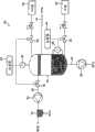
图2示意性地示出了用于从浸没光刻机具抽取多相流体的真空系统的实施例。Figure 2 schematically illustrates an embodiment of a vacuum system for pumping multiphase fluids from an immersion lithography tool.
具体实施方式Detailed ways
参考图2,用于从浸没光刻机具抽取多相流体的系统30包括抽取罐32,其用于接收通过布置在罐32下游侧的泵吸设置从机具抽取的多流流体。罐32通过挠性管路34连接至机具以最小化系统30与机具之间的机械耦合程度,且由此最小化在使用系统30期间产生的振动回传至机具。Referring to FIG. 2 , a
罐32设置为将从机具接收到的流体内的液相与气相分离。在此示例中,从机具接收到的流体包括洁净干燥空气(CDA)与超纯水的混合物,由此罐32容纳用于使CDA从水分离的任何合适的材料及/或结构。但是,罐32可设置为分离从机具接收到的不同的气液混合物。例如,液体可包括水溶液或非水溶液,而气体可以不是CDA。
泵吸设备包括用于从罐32抽取气体的第一泵吸单元36,以及用于从罐32抽取液体的第二泵吸单元38。The pumping device comprises a
第一泵吸单元36可包括用于从罐32抽取气体的任何合适的泵,优选地选择该泵以与从罐32抽取的气体(很可能饱和有液体蒸气)相适应,用于使回传至容纳在罐32中的气体的压力波动最小化,并用于使养护周期相对较长。在本实施例中,第一泵吸单元36可方便地包括用于从罐32抽取CDA的气动喷射泵或水基液体环式泵。为了防止在使用期间振动传递至罐32,利用挠性管路40将第一泵吸单元36连接至罐。因为从第一泵吸单元36的排气可能会饱和有或过度饱和有液体蒸气,在本实施例中,可将水蒸气分离容器42连接至第一泵吸单元36的排气口,容器42包含用于使水蒸气从CDA分离的任何合适材料及/或结构。从CDA抽取的水排出至排出口,而CDA排放至大气。The
第二泵吸单元38可包括用于从罐32抽取液体的任何合适的泵,优选地选择该泵以与从罐32抽取的液体相适应,并用于使养护周期相对较长。在本实施例中,在液体为水的情况下,第二泵吸单元38可方便地包括用于从罐32抽取水的水动喷射泵或隔膜式泵。为了防止在使用期间振动传递至罐32,利用挠性管路44将第二泵吸单元38连接至罐。可选择挠性管路44的内径以限制从罐32至第二泵吸单元38的液体流率。可替换地或可附加地,可在罐32与第二泵吸单元38之间设置不变或可变流率限制器。The
为了最小化从系统30回传至机具内的流体的任何压力波动,系统30包括用于维持罐32内大体恒定压力的压力控制系统。在本实施例中,通过调节罐32内的液体及气体的量来实现此目的。In order to minimize any pressure fluctuations in the fluid passing back from
通过控制器46将容纳在罐32内的液体量维持在大体恒定水平,由此维持罐32内大体恒定量的气体。控制器46连接至用于检测罐32内液体水平的传感器48。传感器48例如可包括液体计、浮标测量计或其他形式的合适传感器。传感器48向控制器46输出表示罐32内液体水平的信号。响应于该信号,控制器46向设置在罐32与连接至罐32的加压外部液体源52之间的可变流率控制装置50输出使得装置50改变至罐32的液体(在本实施例中为水)流率的信号。例如,装置50可以是具有关联于(优选地比例于)从控制器46接收的信号而改变电导的蝶形阀或其他控制阀。通过改变从外部源52至罐的水的流率,控制器46可通过第二泵吸单元38补偿从机具至罐32的液体流率的任何改变,以及/或从罐32的液体抽取速率的任何改变,并由此将罐32内的液体维持在大体恒定的水平。可设置控制器46以处理从传感器48接收的信号以补偿在使用期间在液面中产生的任何波动。The amount of liquid contained within the
在气体占据罐32内大体恒定体积的情况下,包含在从罐接收的多相流体内的气体量的任何改变,以及/或通过第一泵吸单元36的气体抽取速率的任何改变,以及罐32内的任何温度波动,都会改变罐32内气体的压力,并将压力及流率波动传递至机具内的流体。因此,设置压力控制系统以通过还调节罐32内的气体量来维持罐32内大体恒定的压力。With the gas occupying a substantially constant volume within the
为实现此目的,压力控制系统包括连接至用于检测罐32内气体压力的传感器56的控制器54。传感器56例如可包括压力传感器、电容压力计或其他形式的具有足够灵敏度以实现所需的压力控制水平的传感器。传感器56向控制器54输出表示罐32内气体压力的信号。响应于该信号,控制器54向设置在罐32与连接至罐32的加压外部气体源60之间的可变流率控制装置58输出使得装置58改变到罐32的气体(在本实施例中为CDA)流率的信号。可在罐32与第一泵吸单元36之间设置另一可变流率控制装置62,并将其设置为从控制器54接收信号以改变从罐32的气体的流率。例如,装置58、62也可以是具有关联于(优选地比例于)从控制器54接收的信号而改变电导的蝶形阀或其他控制阀。通过控制流入罐32及从罐32流出的气体的流率,控制器54可维持罐32内大体恒定的气体压力。To accomplish this, the pressure control system includes a
系统30因此可提供一种能够从浸光刻机具抽取多相流体同时最小化因此传递至机具内流体的任何压力波动的系统。
Claims (19)
Translated fromChineseApplications Claiming Priority (2)
| Application Number | Priority Date | Filing Date | Title |
|---|---|---|---|
| US10/869,191US7481867B2 (en) | 2004-06-16 | 2004-06-16 | Vacuum system for immersion photolithography |
| US10/869,191 | 2004-06-16 |
Related Parent Applications (1)
| Application Number | Title | Priority Date | Filing Date |
|---|---|---|---|
| CN2005800199796ADivisionCN1997943B (en) | 2004-06-16 | 2005-06-06 | Vacuum system for immersion lithography |
Publications (2)
| Publication Number | Publication Date |
|---|---|
| CN101794081A CN101794081A (en) | 2010-08-04 |
| CN101794081Btrue CN101794081B (en) | 2012-12-26 |
Family
ID=32851367
Family Applications (2)
| Application Number | Title | Priority Date | Filing Date |
|---|---|---|---|
| CN2010101434052AExpired - LifetimeCN101794081B (en) | 2004-06-16 | 2005-06-06 | Vacuum system for immersion photolithography |
| CN2005800199796AExpired - LifetimeCN1997943B (en) | 2004-06-16 | 2005-06-06 | Vacuum system for immersion lithography |
Family Applications After (1)
| Application Number | Title | Priority Date | Filing Date |
|---|---|---|---|
| CN2005800199796AExpired - LifetimeCN1997943B (en) | 2004-06-16 | 2005-06-06 | Vacuum system for immersion lithography |
Country Status (10)
| Country | Link |
|---|---|
| US (7) | US7481867B2 (en) |
| EP (1) | EP1756672B1 (en) |
| JP (3) | JP4772787B2 (en) |
| KR (2) | KR101151767B1 (en) |
| CN (2) | CN101794081B (en) |
| AT (1) | ATE464589T1 (en) |
| DE (1) | DE602005020619D1 (en) |
| GB (1) | GB0414967D0 (en) |
| TW (1) | TWI339131B (en) |
| WO (1) | WO2005124464A2 (en) |
Families Citing this family (35)
| Publication number | Priority date | Publication date | Assignee | Title |
|---|---|---|---|---|
| WO2005006415A1 (en) | 2003-07-09 | 2005-01-20 | Nikon Corporation | Exposure apparatus and method for manufacturing device |
| KR101641011B1 (en)* | 2003-07-28 | 2016-07-19 | 가부시키가이샤 니콘 | Exposure apparatus, device producing method, and exposure apparatus controlling method |
| EP3223053A1 (en) | 2003-09-03 | 2017-09-27 | Nikon Corporation | Apparatus and method for providing fluid for immersion lithography |
| US8054448B2 (en) | 2004-05-04 | 2011-11-08 | Nikon Corporation | Apparatus and method for providing fluid for immersion lithography |
| WO2005119742A1 (en)* | 2004-06-04 | 2005-12-15 | Nikon Corporation | Exposure apparatus, exposure method, and device producing method |
| KR101178755B1 (en) | 2004-06-10 | 2012-08-31 | 가부시키가이샤 니콘 엔지니어링 | Exposure equipment, exposure method and device manufacturing method |
| US8717533B2 (en)* | 2004-06-10 | 2014-05-06 | Nikon Corporation | Exposure apparatus, exposure method, and method for producing device |
| US8508713B2 (en)* | 2004-06-10 | 2013-08-13 | Nikon Corporation | Exposure apparatus, exposure method, and method for producing device |
| US8373843B2 (en)* | 2004-06-10 | 2013-02-12 | Nikon Corporation | Exposure apparatus, exposure method, and method for producing device |
| US20070139628A1 (en)* | 2004-06-10 | 2007-06-21 | Nikon Corporation | Exposure apparatus, exposure method, and method for producing device |
| US7481867B2 (en)* | 2004-06-16 | 2009-01-27 | Edwards Limited | Vacuum system for immersion photolithography |
| US7701550B2 (en) | 2004-08-19 | 2010-04-20 | Asml Netherlands B.V. | Lithographic apparatus and device manufacturing method |
| US7379155B2 (en)* | 2004-10-18 | 2008-05-27 | Asml Netherlands B.V. | Lithographic apparatus and device manufacturing method |
| US7397533B2 (en) | 2004-12-07 | 2008-07-08 | Asml Netherlands B.V. | Lithographic apparatus and device manufacturing method |
| SG124351A1 (en) | 2005-01-14 | 2006-08-30 | Asml Netherlands Bv | Lithographic apparatus and device manufacturing method |
| US8692973B2 (en) | 2005-01-31 | 2014-04-08 | Nikon Corporation | Exposure apparatus and method for producing device |
| KR101513840B1 (en) | 2005-01-31 | 2015-04-20 | 가부시키가이샤 니콘 | Exposure apparatus and method for manufacturing device |
| US8018573B2 (en)* | 2005-02-22 | 2011-09-13 | Asml Netherlands B.V. | Lithographic apparatus and device manufacturing method |
| US7433016B2 (en) | 2005-05-03 | 2008-10-07 | Asml Netherlands B.V. | Lithographic apparatus and device manufacturing method |
| US8514365B2 (en)* | 2007-06-01 | 2013-08-20 | Asml Netherlands B.V. | Lithographic apparatus and device manufacturing method |
| US7924404B2 (en)* | 2007-08-16 | 2011-04-12 | Asml Netherlands B.V. | Lithographic apparatus and device manufacturing method |
| NL1036306A1 (en) | 2007-12-20 | 2009-06-23 | Asml Netherlands Bv | Lithographic apparatus and in-line cleaning apparatus. |
| NL2003226A (en)* | 2008-08-19 | 2010-03-09 | Asml Netherlands Bv | Lithographic apparatus, drying device, metrology apparatus and device manufacturing method. |
| JP2010098172A (en)* | 2008-10-17 | 2010-04-30 | Canon Inc | Liquid recovery device, exposure device and device manufacturing method |
| JP5001343B2 (en) | 2008-12-11 | 2012-08-15 | エーエスエムエル ネザーランズ ビー.ブイ. | Fluid extraction system, immersion lithographic apparatus, and method for reducing pressure fluctuations of an immersion liquid used in an immersion lithographic apparatus |
| NL2004820A (en) | 2009-06-30 | 2011-01-04 | Asml Netherlands Bv | Lithographic apparatus and a method of measuring flow rate in a two phase flow. |
| CA2733042A1 (en)* | 2010-03-01 | 2011-09-01 | Wavefront Technology Solutions Inc. | Method and apparatus for enhancing multiphase extraction of contaminants |
| US20120012191A1 (en)* | 2010-07-16 | 2012-01-19 | Nikon Corporation | Liquid recovery apparatus, exposure apparatus, liquid recovering method, device fabricating method, program, and storage medium |
| NL2009899A (en)* | 2011-12-20 | 2013-06-24 | Asml Netherlands Bv | A pump system, a carbon dioxide supply system, an extraction system, a lithographic apparatus and a device manufacturing method. |
| CN104035288A (en)* | 2014-06-05 | 2014-09-10 | 浙江大学 | Continuous gas-liquid separation device used for immersion type photoetching machine under negative-pressure environment |
| US10646836B2 (en)* | 2014-07-31 | 2020-05-12 | Shigenkaihatsukenkyujyo, Inc. | Cleaning apparatus |
| JP6535649B2 (en)* | 2016-12-12 | 2019-06-26 | 株式会社荏原製作所 | Substrate processing apparatus, discharge method and program |
| CN112684675B (en)* | 2020-12-30 | 2023-02-21 | 浙江启尔机电技术有限公司 | Vacuum system and immersion lithography machine using same |
| TW202439039A (en)* | 2023-03-21 | 2024-10-01 | 聯華電子股份有限公司 | Lithography system and method of detecting fluid leakage in liquid storage tank of the same |
| WO2024208512A1 (en) | 2023-04-04 | 2024-10-10 | Asml Netherlands B.V. | Fluid handling system and method, and method of manufacturing devices |
Citations (2)
| Publication number | Priority date | Publication date | Assignee | Title |
|---|---|---|---|---|
| US4704140A (en)* | 1985-02-15 | 1987-11-03 | Oy Hackman Ab | Procedure and means for use in pumping and volumetry of foodstuff liquids |
| US5610683A (en)* | 1992-11-27 | 1997-03-11 | Canon Kabushiki Kaisha | Immersion type projection exposure apparatus |
Family Cites Families (134)
| Publication number | Priority date | Publication date | Assignee | Title |
|---|---|---|---|---|
| US3314219A (en)* | 1965-03-10 | 1967-04-18 | Bass Brothers Entpr Inc | Drilling mud degassers for oil wells |
| GB1242527A (en) | 1967-10-20 | 1971-08-11 | Kodak Ltd | Optical instruments |
| US3573975A (en) | 1968-07-10 | 1971-04-06 | Ibm | Photochemical fabrication process |
| US3675395A (en)* | 1970-10-09 | 1972-07-11 | Keene Corp | Apparatus for the purification of oils and the like |
| ATE1462T1 (en) | 1979-07-27 | 1982-08-15 | Werner W. Dr. Tabarelli | OPTICAL LITHOGRAPHY PROCESS AND DEVICE FOR COPYING A PATTERN ONTO A SEMICONDUCTOR DISC. |
| US4315760A (en)* | 1980-01-17 | 1982-02-16 | Bij De Leij Jan D | Method and apparatus for degasing, during transportation, a confined volume of liquid to be measured |
| FR2474708B1 (en) | 1980-01-24 | 1987-02-20 | Dme | HIGH-RESOLUTION MICROPHOTOLITHOGRAPHY PROCESS |
| JPS5754317A (en) | 1980-09-19 | 1982-03-31 | Hitachi Ltd | Method and device for forming pattern |
| US4346164A (en) | 1980-10-06 | 1982-08-24 | Werner Tabarelli | Photolithographic method for the manufacture of integrated circuits |
| US4509852A (en) | 1980-10-06 | 1985-04-09 | Werner Tabarelli | Apparatus for the photolithographic manufacture of integrated circuit elements |
| US4390273A (en) | 1981-02-17 | 1983-06-28 | Censor Patent-Und Versuchsanstalt | Projection mask as well as a method and apparatus for the embedding thereof and projection printing system |
| JPS57153433A (en) | 1981-03-18 | 1982-09-22 | Hitachi Ltd | Manufacturing device for semiconductor |
| JPS58202448A (en) | 1982-05-21 | 1983-11-25 | Hitachi Ltd | exposure equipment |
| DD206607A1 (en) | 1982-06-16 | 1984-02-01 | Mikroelektronik Zt Forsch Tech | METHOD AND DEVICE FOR ELIMINATING INTERFERENCE EFFECTS |
| JPS5919912A (en) | 1982-07-26 | 1984-02-01 | Hitachi Ltd | Immersion distance holding device |
| US4466253A (en)* | 1982-12-23 | 1984-08-21 | General Electric Company | Flow control at flash tank of open cycle vapor compression heat pumps |
| DD242880A1 (en) | 1983-01-31 | 1987-02-11 | Kuch Karl Heinz | DEVICE FOR PHOTOLITHOGRAPHIC STRUCTURAL TRANSMISSION |
| DD221563A1 (en) | 1983-09-14 | 1985-04-24 | Mikroelektronik Zt Forsch Tech | IMMERSIONS OBJECTIVE FOR THE STEP-BY-STEP PROJECTION IMAGING OF A MASK STRUCTURE |
| FR2557643B1 (en) | 1983-12-30 | 1986-05-09 | Inst Francais Du Petrole | DEVICE FOR SUPPLYING A DIPHASIC FLUID PUMP AND INSTALLATION FOR PRODUCING HYDROCARBONS COMPRISING SUCH A DEVICE |
| DD224448A1 (en) | 1984-03-01 | 1985-07-03 | Zeiss Jena Veb Carl | DEVICE FOR PHOTOLITHOGRAPHIC STRUCTURAL TRANSMISSION |
| CN85104763B (en)* | 1985-06-13 | 1988-08-24 | 沈汉石 | Method and apparatus for eliminating cavitation in hydraulic system |
| JPS6265326A (en) | 1985-09-18 | 1987-03-24 | Hitachi Ltd | Exposure device |
| JPS62121417A (en) | 1985-11-22 | 1987-06-02 | Hitachi Ltd | Immersion objective lens device |
| US4730634A (en)* | 1986-06-19 | 1988-03-15 | Amoco Corporation | Method and apparatus for controlling production of fluids from a well |
| JPS63157419A (en) | 1986-12-22 | 1988-06-30 | Toshiba Corp | Fine pattern transfer apparatus |
| US4886530A (en) | 1987-10-28 | 1989-12-12 | Sundstrand Corporation | Single stage pump and separator for two phase gas and liquid mixtures |
| US5040020A (en) | 1988-03-31 | 1991-08-13 | Cornell Research Foundation, Inc. | Self-aligned, high resolution resonant dielectric lithography |
| JPH03209479A (en) | 1989-09-06 | 1991-09-12 | Sanee Giken Kk | Exposure method |
| JPH04305917A (en) | 1991-04-02 | 1992-10-28 | Nikon Corp | Close-contact exposure equipment |
| JPH04305915A (en) | 1991-04-02 | 1992-10-28 | Nikon Corp | Adhesion type exposure device |
| JPH0562877A (en) | 1991-09-02 | 1993-03-12 | Yasuko Shinohara | Optical system for lsi manufacturing contraction projection aligner by light |
| JPH06124873A (en)* | 1992-10-09 | 1994-05-06 | Canon Inc | Immersion projection exposure system |
| JP2520833B2 (en) | 1992-12-21 | 1996-07-31 | 東京エレクトロン株式会社 | Immersion type liquid treatment device |
| US5312552A (en)* | 1993-02-02 | 1994-05-17 | Norman J M | Method and apparatus for removing BTX-type gases from a liquid |
| JPH07220990A (en) | 1994-01-28 | 1995-08-18 | Hitachi Ltd | Pattern forming method and exposure apparatus thereof |
| DE69516568T2 (en)* | 1994-03-04 | 2001-01-04 | Ncr International, Inc. | Extended wireless transmission system with modulated reflection |
| JPH08907A (en)* | 1994-06-17 | 1996-01-09 | Miura Co Ltd | Degassing degree adjusting method in vacuum degassing |
| KR960024699U (en) | 1994-12-17 | 1996-07-22 | 임항준 | sticker |
| US6033475A (en) | 1994-12-27 | 2000-03-07 | Tokyo Electron Limited | Resist processing apparatus |
| JPH08316124A (en) | 1995-05-19 | 1996-11-29 | Hitachi Ltd | Projection exposure method and exposure apparatus |
| JPH08316125A (en) | 1995-05-19 | 1996-11-29 | Hitachi Ltd | Projection exposure method and exposure apparatus |
| US6104687A (en) | 1996-08-26 | 2000-08-15 | Digital Papyrus Corporation | Method and apparatus for coupling an optical lens to a disk through a coupling medium having a relatively high index of refraction |
| US6001189A (en)* | 1996-09-30 | 1999-12-14 | Micron Technology, Inc. | Method for reducing gaseous species of contamination in wet processes |
| US5825043A (en) | 1996-10-07 | 1998-10-20 | Nikon Precision Inc. | Focusing and tilting adjustment system for lithography aligner, manufacturing apparatus or inspection apparatus |
| JP3612920B2 (en) | 1997-02-14 | 2005-01-26 | ソニー株式会社 | Exposure apparatus for producing an optical recording medium master |
| JPH10255319A (en) | 1997-03-12 | 1998-09-25 | Hitachi Maxell Ltd | Master exposure apparatus and method |
| JP3747566B2 (en) | 1997-04-23 | 2006-02-22 | 株式会社ニコン | Immersion exposure equipment |
| JP3817836B2 (en) | 1997-06-10 | 2006-09-06 | 株式会社ニコン | EXPOSURE APPARATUS, ITS MANUFACTURING METHOD, EXPOSURE METHOD, AND DEVICE MANUFACTURING METHOD |
| US5900354A (en) | 1997-07-03 | 1999-05-04 | Batchelder; John Samuel | Method for optical inspection and lithography |
| JPH11176727A (en) | 1997-12-11 | 1999-07-02 | Nikon Corp | Projection exposure equipment |
| EP1039511A4 (en) | 1997-12-12 | 2005-03-02 | Nikon Corp | Projection exposure method and projection aligner |
| WO1999049504A1 (en) | 1998-03-26 | 1999-09-30 | Nikon Corporation | Projection exposure method and system |
| JP2000058436A (en) | 1998-08-11 | 2000-02-25 | Nikon Corp | Projection exposure apparatus and exposure method |
| US6247903B1 (en)* | 1999-03-26 | 2001-06-19 | Lam Research Corporation | Pressure fluctuation dampening system |
| TWI242111B (en) | 1999-04-19 | 2005-10-21 | Asml Netherlands Bv | Gas bearings for use in vacuum chambers and their application in lithographic projection apparatus |
| JP4504479B2 (en) | 1999-09-21 | 2010-07-14 | オリンパス株式会社 | Immersion objective lens for microscope |
| EP1409834A2 (en)* | 2000-01-17 | 2004-04-21 | Lattice Intellectual Property Limited | Slugging control |
| JP2001272604A (en) | 2000-03-27 | 2001-10-05 | Olympus Optical Co Ltd | Immersion objective lens and optical device using the same |
| TW591653B (en) | 2000-08-08 | 2004-06-11 | Koninkl Philips Electronics Nv | Method of manufacturing an optically scannable information carrier |
| SE517821C2 (en)* | 2000-09-29 | 2002-07-16 | Tetra Laval Holdings & Finance | Method and apparatus for continuously venting a liquid |
| KR100866818B1 (en) | 2000-12-11 | 2008-11-04 | 가부시키가이샤 니콘 | Projection optical system and exposure apparatus comprising the same |
| JP2002257137A (en) | 2001-02-27 | 2002-09-11 | Koyo Seiko Co Ltd | Magnetic bearing device |
| JP2002257138A (en) | 2001-02-28 | 2002-09-11 | Canon Inc | Hydrostatic bearing device, and stage apparatus, exposure apparatus and device manufacturing method using the same |
| US20020163629A1 (en) | 2001-05-07 | 2002-11-07 | Michael Switkes | Methods and apparatus employing an index matching medium |
| US8180871B2 (en)* | 2001-05-23 | 2012-05-15 | International Business Machines Corporation | Dynamic redeployment of services in a computing network |
| US6600547B2 (en) | 2001-09-24 | 2003-07-29 | Nikon Corporation | Sliding seal |
| US6897941B2 (en) | 2001-11-07 | 2005-05-24 | Applied Materials, Inc. | Optical spot grid array printer |
| DE10210899A1 (en) | 2002-03-08 | 2003-09-18 | Zeiss Carl Smt Ag | Refractive projection lens for immersion lithography |
| DE10229818A1 (en) | 2002-06-28 | 2004-01-15 | Carl Zeiss Smt Ag | Focus detection method and imaging system with focus detection system |
| US20040154641A1 (en)* | 2002-05-17 | 2004-08-12 | P.C.T. Systems, Inc. | Substrate processing apparatus and method |
| TWI249082B (en) | 2002-08-23 | 2006-02-11 | Nikon Corp | Projection optical system and method for photolithography and exposure apparatus and method using same |
| US6788477B2 (en)* | 2002-10-22 | 2004-09-07 | Taiwan Semiconductor Manufacturing Co., Ltd. | Apparatus for method for immersion lithography |
| CN101470360B (en) | 2002-11-12 | 2013-07-24 | Asml荷兰有限公司 | Immersion lithographic apparatus and device manufacturing method |
| SG121822A1 (en)* | 2002-11-12 | 2006-05-26 | Asml Netherlands Bv | Lithographic apparatus and device manufacturing method |
| EP1420298B1 (en)* | 2002-11-12 | 2013-02-20 | ASML Netherlands B.V. | Lithographic apparatus |
| CN100568101C (en)* | 2002-11-12 | 2009-12-09 | Asml荷兰有限公司 | Photolithography apparatus and device manufacturing method |
| DE60335595D1 (en) | 2002-11-12 | 2011-02-17 | Asml Netherlands Bv | Immersion lithographic apparatus and method of making a device |
| KR100585476B1 (en) | 2002-11-12 | 2006-06-07 | 에이에스엠엘 네델란즈 비.브이. | Lithographic Apparatus and Device Manufacturing Method |
| SG131766A1 (en) | 2002-11-18 | 2007-05-28 | Asml Netherlands Bv | Lithographic apparatus and device manufacturing method |
| SG121829A1 (en) | 2002-11-29 | 2006-05-26 | Asml Netherlands Bv | Lithographic apparatus and device manufacturing method |
| EP1424599B1 (en)* | 2002-11-29 | 2008-03-12 | ASML Netherlands B.V. | Lithographic apparatus and device manufacturing method |
| DE10258718A1 (en) | 2002-12-09 | 2004-06-24 | Carl Zeiss Smt Ag | Projection lens, in particular for microlithography, and method for tuning a projection lens |
| JP4529433B2 (en)* | 2002-12-10 | 2010-08-25 | 株式会社ニコン | Exposure apparatus, exposure method, and device manufacturing method |
| JP4352874B2 (en) | 2002-12-10 | 2009-10-28 | 株式会社ニコン | Exposure apparatus and device manufacturing method |
| WO2004053955A1 (en) | 2002-12-10 | 2004-06-24 | Nikon Corporation | Exposure system and device producing method |
| DE10257766A1 (en) | 2002-12-10 | 2004-07-15 | Carl Zeiss Smt Ag | Method for setting a desired optical property of a projection lens and microlithographic projection exposure system |
| AU2003289272A1 (en) | 2002-12-10 | 2004-06-30 | Nikon Corporation | Surface position detection apparatus, exposure method, and device porducing method |
| KR101101737B1 (en) | 2002-12-10 | 2012-01-05 | 가부시키가이샤 니콘 | Exposure apparatus, exposure method and method for manufacturing device |
| EP1571694A4 (en) | 2002-12-10 | 2008-10-15 | Nikon Corp | Exposure apparatus and method for manufacturing device |
| EP1429190B1 (en) | 2002-12-10 | 2012-05-09 | Canon Kabushiki Kaisha | Exposure apparatus and method |
| KR20120127755A (en) | 2002-12-10 | 2012-11-23 | 가부시키가이샤 니콘 | Exposure apparatus and method for manufacturing device |
| JP4608876B2 (en) | 2002-12-10 | 2011-01-12 | 株式会社ニコン | Exposure apparatus and device manufacturing method |
| KR20050085026A (en) | 2002-12-10 | 2005-08-29 | 가부시키가이샤 니콘 | Optical device and projection exposure apparatus using such optical device |
| WO2004053951A1 (en) | 2002-12-10 | 2004-06-24 | Nikon Corporation | Exposure method, exposure apparatus and method for manufacturing device |
| WO2004053950A1 (en) | 2002-12-10 | 2004-06-24 | Nikon Corporation | Exposure apparatus and method for manufacturing device |
| AU2003289237A1 (en) | 2002-12-10 | 2004-06-30 | Nikon Corporation | Exposure apparatus and method for manufacturing device |
| JP4232449B2 (en) | 2002-12-10 | 2009-03-04 | 株式会社ニコン | Exposure method, exposure apparatus, and device manufacturing method |
| EP1573730B1 (en) | 2002-12-13 | 2009-02-25 | Koninklijke Philips Electronics N.V. | Liquid removal in a method and device for irradiating spots on a layer |
| EP1584089B1 (en) | 2002-12-19 | 2006-08-02 | Koninklijke Philips Electronics N.V. | Method and device for irradiating spots on a layer |
| US7514699B2 (en) | 2002-12-19 | 2009-04-07 | Koninklijke Philips Electronics N.V. | Method and device for irradiating spots on a layer |
| US6781670B2 (en) | 2002-12-30 | 2004-08-24 | Intel Corporation | Immersion lithography |
| JP4428115B2 (en) | 2003-04-11 | 2010-03-10 | 株式会社ニコン | Immersion lithography system |
| JP2004320016A (en) | 2003-04-11 | 2004-11-11 | Nikon Corp | Immersion lithography system |
| JP2005277363A (en)* | 2003-05-23 | 2005-10-06 | Nikon Corp | Exposure apparatus and device manufacturing method |
| EP2261741A3 (en) | 2003-06-11 | 2011-05-25 | ASML Netherlands B.V. | Lithographic apparatus and device manufacturing method |
| US7317504B2 (en) | 2004-04-08 | 2008-01-08 | Asml Netherlands B.V. | Lithographic apparatus and device manufacturing method |
| US6867844B2 (en) | 2003-06-19 | 2005-03-15 | Asml Holding N.V. | Immersion photolithography system and method using microchannel nozzles |
| JP4343597B2 (en) | 2003-06-25 | 2009-10-14 | キヤノン株式会社 | Exposure apparatus and device manufacturing method |
| US6809794B1 (en) | 2003-06-27 | 2004-10-26 | Asml Holding N.V. | Immersion photolithography system and method using inverted wafer-projection optics interface |
| WO2005006415A1 (en)* | 2003-07-09 | 2005-01-20 | Nikon Corporation | Exposure apparatus and method for manufacturing device |
| WO2005015315A2 (en)* | 2003-07-24 | 2005-02-17 | Carl Zeiss Smt Ag | Microlithographic projection exposure system, and method for introducing an immersion liquid into an immersion chamber |
| US7779781B2 (en) | 2003-07-31 | 2010-08-24 | Asml Netherlands B.V. | Lithographic apparatus and device manufacturing method |
| US6954256B2 (en) | 2003-08-29 | 2005-10-11 | Asml Netherlands B.V. | Gradient immersion lithography |
| EP3223053A1 (en) | 2003-09-03 | 2017-09-27 | Nikon Corporation | Apparatus and method for providing fluid for immersion lithography |
| JP4378136B2 (en) | 2003-09-04 | 2009-12-02 | キヤノン株式会社 | Exposure apparatus and device manufacturing method |
| EP2267536B1 (en) | 2003-10-28 | 2017-04-19 | ASML Netherlands B.V. | Lithographic apparatus |
| US7545481B2 (en) | 2003-11-24 | 2009-06-09 | Asml Netherlands B.V. | Lithographic apparatus and device manufacturing method |
| JP2005175176A (en) | 2003-12-11 | 2005-06-30 | Nikon Corp | Exposure method and device manufacturing method |
| US7589818B2 (en) | 2003-12-23 | 2009-09-15 | Asml Netherlands B.V. | Lithographic apparatus, alignment apparatus, device manufacturing method, and a method of converting an apparatus |
| US7394521B2 (en) | 2003-12-23 | 2008-07-01 | Asml Netherlands B.V. | Lithographic apparatus and device manufacturing method |
| JP4954444B2 (en)* | 2003-12-26 | 2012-06-13 | 株式会社ニコン | Channel forming member, exposure apparatus, and device manufacturing method |
| JP2005191393A (en) | 2003-12-26 | 2005-07-14 | Canon Inc | Exposure method and apparatus |
| EP1703548B1 (en)* | 2004-01-05 | 2010-05-12 | Nikon Corporation | Exposure apparatus, exposure method, and device producing method |
| JP4513590B2 (en)* | 2004-02-19 | 2010-07-28 | 株式会社ニコン | Optical component and exposure apparatus |
| US8054448B2 (en)* | 2004-05-04 | 2011-11-08 | Nikon Corporation | Apparatus and method for providing fluid for immersion lithography |
| KR101178755B1 (en)* | 2004-06-10 | 2012-08-31 | 가부시키가이샤 니콘 엔지니어링 | Exposure equipment, exposure method and device manufacturing method |
| US20070139628A1 (en)* | 2004-06-10 | 2007-06-21 | Nikon Corporation | Exposure apparatus, exposure method, and method for producing device |
| US8373843B2 (en) | 2004-06-10 | 2013-02-12 | Nikon Corporation | Exposure apparatus, exposure method, and method for producing device |
| US8508713B2 (en) | 2004-06-10 | 2013-08-13 | Nikon Corporation | Exposure apparatus, exposure method, and method for producing device |
| JP4515335B2 (en)* | 2004-06-10 | 2010-07-28 | 株式会社ニコン | Exposure apparatus, nozzle member, and device manufacturing method |
| US8717533B2 (en) | 2004-06-10 | 2014-05-06 | Nikon Corporation | Exposure apparatus, exposure method, and method for producing device |
| US7481867B2 (en)* | 2004-06-16 | 2009-01-27 | Edwards Limited | Vacuum system for immersion photolithography |
| US7701550B2 (en) | 2004-08-19 | 2010-04-20 | Asml Netherlands B.V. | Lithographic apparatus and device manufacturing method |
| US7379155B2 (en) | 2004-10-18 | 2008-05-27 | Asml Netherlands B.V. | Lithographic apparatus and device manufacturing method |
- 2004
- 2004-06-16USUS10/869,191patent/US7481867B2/ennot_activeExpired - Fee Related
- 2004-07-02GBGBGB0414967.0Apatent/GB0414967D0/ennot_activeCeased
- 2005
- 2005-06-06JPJP2007516020Apatent/JP4772787B2/ennot_activeExpired - Fee Related
- 2005-06-06KRKR1020067026392Apatent/KR101151767B1/ennot_activeExpired - Fee Related
- 2005-06-06CNCN2010101434052Apatent/CN101794081B/ennot_activeExpired - Lifetime
- 2005-06-06CNCN2005800199796Apatent/CN1997943B/ennot_activeExpired - Lifetime
- 2005-06-06WOPCT/GB2005/002205patent/WO2005124464A2/ennot_activeApplication Discontinuation
- 2005-06-06ATAT05747245Tpatent/ATE464589T1/ennot_activeIP Right Cessation
- 2005-06-06EPEP05747245Apatent/EP1756672B1/ennot_activeCeased
- 2005-06-06DEDE602005020619Tpatent/DE602005020619D1/ennot_activeExpired - Lifetime
- 2005-06-06KRKR1020117011954Apatent/KR101341923B1/ennot_activeExpired - Fee Related
- 2005-06-16TWTW094120050Apatent/TWI339131B/ennot_activeIP Right Cessation
- 2008
- 2008-12-19USUS12/340,326patent/US8164734B2/ennot_activeExpired - Fee Related
- 2010
- 2010-03-19JPJP2010063578Apatent/JP5226025B2/ennot_activeExpired - Fee Related
- 2011
- 2011-05-02JPJP2011102691Apatent/JP5226101B2/ennot_activeExpired - Fee Related
- 2011-07-20USUS13/187,166patent/US8830440B2/ennot_activeExpired - Fee Related
- 2014
- 2014-08-26USUS14/469,389patent/US9507270B2/ennot_activeExpired - Fee Related
- 2016
- 2016-11-28USUS15/362,530patent/US9857699B2/ennot_activeExpired - Lifetime
- 2017
- 2017-12-28USUS15/857,368patent/US10168624B2/ennot_activeExpired - Lifetime
- 2018
- 2018-11-28USUS16/202,170patent/US20190094715A1/ennot_activeAbandoned
Patent Citations (2)
| Publication number | Priority date | Publication date | Assignee | Title |
|---|---|---|---|---|
| US4704140A (en)* | 1985-02-15 | 1987-11-03 | Oy Hackman Ab | Procedure and means for use in pumping and volumetry of foodstuff liquids |
| US5610683A (en)* | 1992-11-27 | 1997-03-11 | Canon Kabushiki Kaisha | Immersion type projection exposure apparatus |
Non-Patent Citations (1)
| Title |
|---|
| JP特开平8-907A 1996.01.09 |
Also Published As
| Publication number | Publication date |
|---|---|
| TWI339131B (en) | 2011-03-21 |
| US9507270B2 (en) | 2016-11-29 |
| US8830440B2 (en) | 2014-09-09 |
| US10168624B2 (en) | 2019-01-01 |
| JP2011176352A (en) | 2011-09-08 |
| US20090201471A1 (en) | 2009-08-13 |
| KR20070021260A (en) | 2007-02-22 |
| GB0414967D0 (en) | 2004-08-04 |
| US7481867B2 (en) | 2009-01-27 |
| CN1997943A (en) | 2007-07-11 |
| US20190094715A1 (en) | 2019-03-28 |
| DE602005020619D1 (en) | 2010-05-27 |
| US20170075233A1 (en) | 2017-03-16 |
| US20140362358A1 (en) | 2014-12-11 |
| JP5226101B2 (en) | 2013-07-03 |
| KR101151767B1 (en) | 2012-06-15 |
| JP2010141363A (en) | 2010-06-24 |
| JP2008503079A (en) | 2008-01-31 |
| US20110273681A1 (en) | 2011-11-10 |
| WO2005124464A2 (en) | 2005-12-29 |
| KR20110063699A (en) | 2011-06-13 |
| US9857699B2 (en) | 2018-01-02 |
| US20050282405A1 (en) | 2005-12-22 |
| EP1756672B1 (en) | 2010-04-14 |
| JP4772787B2 (en) | 2011-09-14 |
| CN1997943B (en) | 2010-05-05 |
| JP5226025B2 (en) | 2013-07-03 |
| ATE464589T1 (en) | 2010-04-15 |
| US8164734B2 (en) | 2012-04-24 |
| CN101794081A (en) | 2010-08-04 |
| US20180120715A1 (en) | 2018-05-03 |
| KR101341923B1 (en) | 2013-12-16 |
| EP1756672A2 (en) | 2007-02-28 |
| TW200615039A (en) | 2006-05-16 |
| WO2005124464A3 (en) | 2006-06-08 |
Similar Documents
| Publication | Publication Date | Title |
|---|---|---|
| CN101794081B (en) | Vacuum system for immersion photolithography | |
| US10248033B2 (en) | Lithographic apparatus and device manufacturing method | |
| US10705439B2 (en) | Lithographic apparatus and device manufacturing method | |
| KR101135673B1 (en) | Fluid Extraction system, Lithographic Apparatus and Device Manufacturing Method |
Legal Events
| Date | Code | Title | Description |
|---|---|---|---|
| C06 | Publication | ||
| PB01 | Publication | ||
| C10 | Entry into substantive examination | ||
| SE01 | Entry into force of request for substantive examination | ||
| C14 | Grant of patent or utility model | ||
| GR01 | Patent grant | ||
| CX01 | Expiry of patent term | Granted publication date:20121226 | |
| CX01 | Expiry of patent term |