CN101785884B - Portable ejection and injection device - Google Patents
Portable ejection and injection deviceDownload PDFInfo
- Publication number
- CN101785884B CN101785884BCN 200910263749CN200910263749ACN101785884BCN 101785884 BCN101785884 BCN 101785884BCN 200910263749CN200910263749CN 200910263749CN 200910263749 ACN200910263749 ACN 200910263749ACN 101785884 BCN101785884 BCN 101785884B
- Authority
- CN
- China
- Prior art keywords
- mentioned
- push rod
- ejection
- push
- lubricant
- Prior art date
- Legal status (The legal status is an assumption and is not a legal conclusion. Google has not performed a legal analysis and makes no representation as to the accuracy of the status listed.)
- Expired - Fee Related
Links
- 238000002347injectionMethods0.000titleclaimsdescription84
- 239000007924injectionSubstances0.000titleclaimsdescription84
- 239000007788liquidSubstances0.000claimsabstractdescription118
- 239000000314lubricantSubstances0.000claimsabstractdescription35
- 210000000436anusAnatomy0.000claimsabstractdescription25
- 230000002093peripheral effectEffects0.000claimsdescription28
- 239000007921spraySubstances0.000claimsdescription26
- 238000003780insertionMethods0.000claimsdescription21
- 230000037431insertionEffects0.000claimsdescription21
- 210000000056organAnatomy0.000claimsdescription20
- 230000001568sexual effectEffects0.000claimsdescription19
- 238000007789sealingMethods0.000claimsdescription7
- 235000015110jelliesNutrition0.000claims1
- 239000008274jellySubstances0.000claims1
- 239000000126substanceSubstances0.000abstractdescription12
- 239000003814drugSubstances0.000description105
- 238000005507sprayingMethods0.000description22
- 239000000243solutionSubstances0.000description15
- 230000001050lubricating effectEffects0.000description13
- 239000002775capsuleSubstances0.000description11
- 229940079593drugDrugs0.000description9
- 239000012530fluidSubstances0.000description9
- 238000005452bendingMethods0.000description8
- 210000001215vaginaAnatomy0.000description8
- 229920000122acrylonitrile butadiene styrenePolymers0.000description6
- 201000010099diseaseDiseases0.000description6
- 208000037265diseases, disorders, signs and symptomsDiseases0.000description6
- 229920001971elastomerPolymers0.000description6
- 210000003811fingerAnatomy0.000description6
- 208000015181infectious diseaseDiseases0.000description5
- 239000002390adhesive tapeSubstances0.000description4
- 239000005060rubberSubstances0.000description4
- 239000000853adhesiveSubstances0.000description3
- 230000001070adhesive effectEffects0.000description3
- 210000001072colonAnatomy0.000description3
- 239000003433contraceptive agentSubstances0.000description3
- 239000008155medical solutionSubstances0.000description3
- 238000005192partitionMethods0.000description3
- 210000003813thumbAnatomy0.000description3
- 230000000903blocking effectEffects0.000description2
- 230000002254contraceptive effectEffects0.000description2
- 230000000694effectsEffects0.000description2
- 239000000806elastomerSubstances0.000description2
- 230000001151other effectEffects0.000description2
- 239000006187pillSubstances0.000description2
- 229920003002synthetic resinPolymers0.000description2
- 239000000057synthetic resinSubstances0.000description2
- 241001391944Commicarpus scandensSpecies0.000description1
- 239000000443aerosolSubstances0.000description1
- 230000003444anaesthetic effectEffects0.000description1
- 229940035674anestheticsDrugs0.000description1
- 230000001754anti-pyretic effectEffects0.000description1
- 239000002221antipyreticSubstances0.000description1
- 229940125716antipyretic agentDrugs0.000description1
- 239000003795chemical substances by applicationSubstances0.000description1
- 239000012459cleaning agentSubstances0.000description1
- 230000003749cleanlinessEffects0.000description1
- 239000000084colloidal systemSubstances0.000description1
- -1colon cleansersSubstances0.000description1
- 229940124558contraceptive agentDrugs0.000description1
- 230000002354daily effectEffects0.000description1
- 238000007599dischargingMethods0.000description1
- 230000006806disease preventionEffects0.000description1
- 230000003203everyday effectEffects0.000description1
- 229940124566female contraceptive agentDrugs0.000description1
- 239000003037female contraceptive agentSubstances0.000description1
- 239000003193general anesthetic agentSubstances0.000description1
- 210000004392genitaliaAnatomy0.000description1
- 239000006210lotionSubstances0.000description1
- 238000000034methodMethods0.000description1
- 229920003023plasticPolymers0.000description1
- 239000004033plasticSubstances0.000description1
- 230000002265preventionEffects0.000description1
- 210000004999sex organAnatomy0.000description1
- 229940126585therapeutic drugDrugs0.000description1
- 238000005406washingMethods0.000description1
Images


Classifications
- A—HUMAN NECESSITIES
- A61—MEDICAL OR VETERINARY SCIENCE; HYGIENE
- A61M—DEVICES FOR INTRODUCING MEDIA INTO, OR ONTO, THE BODY; DEVICES FOR TRANSDUCING BODY MEDIA OR FOR TAKING MEDIA FROM THE BODY; DEVICES FOR PRODUCING OR ENDING SLEEP OR STUPOR
- A61M31/00—Devices for introducing or retaining media, e.g. remedies, in cavities of the body
- A—HUMAN NECESSITIES
- A61—MEDICAL OR VETERINARY SCIENCE; HYGIENE
- A61M—DEVICES FOR INTRODUCING MEDIA INTO, OR ONTO, THE BODY; DEVICES FOR TRANSDUCING BODY MEDIA OR FOR TAKING MEDIA FROM THE BODY; DEVICES FOR PRODUCING OR ENDING SLEEP OR STUPOR
- A61M5/00—Devices for bringing media into the body in a subcutaneous, intra-vascular or intramuscular way; Accessories therefor, e.g. filling or cleaning devices, arm-rests
- A61M5/178—Syringes
- A61M5/24—Ampoule syringes, i.e. syringes with needle for use in combination with replaceable ampoules or carpules, e.g. automatic
- A61M5/2422—Ampoule syringes, i.e. syringes with needle for use in combination with replaceable ampoules or carpules, e.g. automatic using emptying means to expel or eject media, e.g. pistons, deformation of the ampoule, or telescoping of the ampoule
- A61M5/2425—Ampoule syringes, i.e. syringes with needle for use in combination with replaceable ampoules or carpules, e.g. automatic using emptying means to expel or eject media, e.g. pistons, deformation of the ampoule, or telescoping of the ampoule by compression of deformable ampoule or carpule wall
- A—HUMAN NECESSITIES
- A61—MEDICAL OR VETERINARY SCIENCE; HYGIENE
- A61M—DEVICES FOR INTRODUCING MEDIA INTO, OR ONTO, THE BODY; DEVICES FOR TRANSDUCING BODY MEDIA OR FOR TAKING MEDIA FROM THE BODY; DEVICES FOR PRODUCING OR ENDING SLEEP OR STUPOR
- A61M5/00—Devices for bringing media into the body in a subcutaneous, intra-vascular or intramuscular way; Accessories therefor, e.g. filling or cleaning devices, arm-rests
- A61M5/178—Syringes
- A61M5/24—Ampoule syringes, i.e. syringes with needle for use in combination with replaceable ampoules or carpules, e.g. automatic
- A61M5/2455—Ampoule syringes, i.e. syringes with needle for use in combination with replaceable ampoules or carpules, e.g. automatic with sealing means to be broken or opened
- A61M5/2459—Ampoule syringes, i.e. syringes with needle for use in combination with replaceable ampoules or carpules, e.g. automatic with sealing means to be broken or opened upon internal pressure increase, e.g. pierced or burst
- A—HUMAN NECESSITIES
- A61—MEDICAL OR VETERINARY SCIENCE; HYGIENE
- A61M—DEVICES FOR INTRODUCING MEDIA INTO, OR ONTO, THE BODY; DEVICES FOR TRANSDUCING BODY MEDIA OR FOR TAKING MEDIA FROM THE BODY; DEVICES FOR PRODUCING OR ENDING SLEEP OR STUPOR
- A61M5/00—Devices for bringing media into the body in a subcutaneous, intra-vascular or intramuscular way; Accessories therefor, e.g. filling or cleaning devices, arm-rests
- A61M5/178—Syringes
- A61M5/31—Details
- A61M5/315—Pistons; Piston-rods; Guiding, blocking or restricting the movement of the rod or piston; Appliances on the rod for facilitating dosing ; Dosing mechanisms
- A61M5/31511—Piston or piston-rod constructions, e.g. connection of piston with piston-rod
- A61M5/31515—Connection of piston with piston rod
- A—HUMAN NECESSITIES
- A61—MEDICAL OR VETERINARY SCIENCE; HYGIENE
- A61M—DEVICES FOR INTRODUCING MEDIA INTO, OR ONTO, THE BODY; DEVICES FOR TRANSDUCING BODY MEDIA OR FOR TAKING MEDIA FROM THE BODY; DEVICES FOR PRODUCING OR ENDING SLEEP OR STUPOR
- A61M5/00—Devices for bringing media into the body in a subcutaneous, intra-vascular or intramuscular way; Accessories therefor, e.g. filling or cleaning devices, arm-rests
- A61M5/50—Devices for bringing media into the body in a subcutaneous, intra-vascular or intramuscular way; Accessories therefor, e.g. filling or cleaning devices, arm-rests having means for preventing re-use, or for indicating if defective, used, tampered with or unsterile
- A61M5/5066—Means for preventing re-use by disconnection of piston and piston-rod
Landscapes
- Health & Medical Sciences (AREA)
- Engineering & Computer Science (AREA)
- Anesthesiology (AREA)
- Biomedical Technology (AREA)
- Heart & Thoracic Surgery (AREA)
- Hematology (AREA)
- Life Sciences & Earth Sciences (AREA)
- Animal Behavior & Ethology (AREA)
- General Health & Medical Sciences (AREA)
- Public Health (AREA)
- Veterinary Medicine (AREA)
- Infusion, Injection, And Reservoir Apparatuses (AREA)
Abstract
Description
Translated fromChinese本申请是发明名称为“便携式喷出注入器具”、申请日为2006年6月26日并且申请号为200480039124.5的发明专利申请的分案申请。This application is a divisional application of the patent application for invention with the title of "portable ejection and injection device", the application date being June 26, 2006, and the application number being 200480039124.5.
技术领域technical field
本发明涉及一种向人的特定部位注入药液或润滑剂的注入器具,特别是涉及一种将预先装填到注入器具内部的装填部中的规定的药液或润滑剂喷出并注入到女性的性器官或人的肛门的器具。所谓喷出,包括受到压力后慢慢流出到受到压力后势头很猛地飞出(射出)这各种形式。药液有避孕药、麻醉剂、洗肠剂、解热剂等,润滑剂有润滑洗液、润滑凝胶、润滑胶体等,根据目的进行选择。The present invention relates to an injection device for injecting a liquid medicine or a lubricant into a specific part of a person, and in particular to a device for spraying and injecting a prescribed liquid medicine or lubricant pre-filled in a filling part of the injection device into a female body. genital or human anal apparatus. The so-called ejection includes various forms such as slowly flowing out after receiving pressure to flying out (injection) with great momentum after receiving pressure. The medicinal solution includes contraceptives, anesthetics, colon cleansers, antipyretics, etc., and the lubricant includes lubricating lotion, lubricating gel, lubricating colloid, etc., which are selected according to the purpose.
背景技术Background technique
如今的社会,生活烦杂且每天不断忙碌。为了度过这样的现代生活,人们开发了许多解决日常生活问题的器具并加以使用。尽管如此,对用于将女性的避孕药或治疗药插入人体内的既简便又卫生的器具的开发还不够。即,尽管保持女性的性器官(阴道周边)、人肛门周围的清洁对于预防疾病来说是至关重要的,但目前仍然是直接用人手来进行避孕药的注入以及洗肠药等规定药液向肛门的注入。这些操作非常麻烦且不易进行,还不卫生。In today's society, life is complicated and busy every day. In order to spend such a modern life, people have developed and used many appliances for solving daily problems. Nevertheless, the development of simple and hygienic devices for inserting female contraceptives or therapeutic drugs into the human body has not been sufficient. That is, although keeping women's sexual organs (periphery of the vagina) and the cleanliness around the anus of the human body is crucial for disease prevention, at present the injection of contraceptive pills and prescribed medicinal liquids such as colon cleansing medicines are still directly carried out by hand. Anal injection. These operations are very troublesome and difficult to carry out, also unhygienic.
由于女性的性器官(阴道)和人的肛门(肛门内)都是非常敏感脆弱的部分,所以在向这些部位注入润滑剂以及避孕药、用于性病治疗和预防的药液、规定的洗肠药等时,就必须非常注意。Since the female sexual organs (vagina) and the human anus (inside the anus) are very sensitive and fragile parts, lubricants and contraceptive pills, medicinal liquids for STD treatment and prevention, and prescribed colon cleansing medicines are injected into these parts When waiting, you must be very careful.
然而,实际的情况是,尚未开发出一种能有效进行女性性器官和人肛门的清洗、向其内部(阴道内或肛门内)注入规定药液/润滑剂的简单且安全的器具。这是因为,这样的器具要求无论在什么时间什么场所,都要便于携带,从而在使用上存在各种限制。However, the actual situation is that a simple and safe device that can effectively clean female sexual organs and human anus and inject prescribed liquid medicine/lubricant into it (in the vagina or in the anus) has not yet been developed. This is because such an appliance is required to be portable at any time and place, and there are various restrictions on use.
作为这种药液注入器具,例如有日本专利申请特开2001-187151号中公开的注入器具。该注入器具具备在前端形成有润滑液流出口的塑料筒体,并且采用了向润滑液流出口推入设置于筒体内的推入杆的形式,使填充在上述筒体前端的润滑液从润滑液流出口流出。因而,若使用它则可容易地向女性的性器官进行润滑液的注入等。As such a drug solution injector, there is an injector disclosed in Japanese Patent Application Laid-Open No. 2001-187151, for example. The injector is provided with a plastic cylinder having a lubricating fluid outlet at the front end, and adopts the form of pushing a push-in rod provided in the cylinder to the lubricating fluid outlet, so that the lubricating fluid filled in the front end of the cylinder can flow from the lubricating fluid to the lubricating fluid outlet. The liquid flows out of the outlet. Therefore, if it is used, injection of lubricating fluid etc. into female sexual organs can be easily performed.
但是,上述药液注入器具还没有找出对策以解决润滑液的泄漏,所以存在下述问题:携带时从润滑液流出口流出润滑液的可能性较高,不适合携带。此外,还存在下述问题:已经使用了一次的器具有可能被直接再次使用,再使用时很不卫生,有可能感染疾病。进而还有如下问题:要使用上述注入器具,必须使润滑液流出口朝向上方(或是斜上方),从下侧向上侧推入推入杆,所以使用便利性较差。However, no countermeasures have been found to solve the leakage of the lubricating liquid in the above-mentioned liquid medicine injector, so there is a problem that the lubricating liquid may flow out from the lubricating liquid outlet when it is carried, and it is not suitable for carrying. In addition, there is also the following problem: the device that has been used once may be directly used again, which is very unhygienic when used again, and may be infected with diseases. Furthermore, there is a problem that in order to use the above-mentioned injector, the lubricating fluid outlet must be directed upward (or obliquely upward), and the push-in rod must be pushed in from the lower side to the upper side, so the convenience of use is poor.
专利文献1:特开2004-187151号公报。Patent Document 1: Japanese Unexamined Patent Publication No. 2004-187151.
发明内容Contents of the invention
鉴于此,本发明的目的是提供一种便携式喷出注入器具,其能向女性性器官或人的肛门喷出药液或润滑剂而对该部位进行清洗,根据需要还可以直接注入到内部(阴道内或肛门内)。In view of this, the purpose of the present invention is to provide a portable ejection injection device, which can spray medicinal liquid or lubricant to the female sexual organs or people's anus to clean the position, and can also directly inject into the inside (vagina) as required. inside or inside the anus).
此外,本发明的另一目的是提供一种便携式喷出注入器具,其从流出口泄漏药液或润滑剂的可能性较小。Furthermore, another object of the present invention is to provide a portable dispensing and injecting device which is less likely to leak a medical solution or a lubricant from an outflow port.
本发明的又一目的是提供一种便携式喷出注入器具,其考虑到了疾病的感染和卫生问题。Yet another object of the present invention is to provide a portable spray injection device that takes into account the infection of diseases and hygiene issues.
此外,本发明的又一目的是提供一种便携式喷出注入器具,其在携带时不会有药液流出。In addition, another object of the present invention is to provide a portable spraying and injecting device, which does not cause liquid medicine to flow out when it is carried.
另外,本发明的又一目的是提供一种便携式喷出注入器具,其易于喷出注入药液或润滑剂。In addition, another object of the present invention is to provide a portable ejection and injection tool that can easily eject and inject liquid medicine or lubricant.
为此,本发明的便携式喷出注入器具,是一种便携式喷出注入器具,向女性的性器官或肛门或者其内部喷出注入药液或润滑剂,上述便携式喷出注入器具由筒体、药液或润滑剂、活塞部、推入杆构成,上述筒体具有插入部、装填部、纵长部和漏斗状部,上述筒体的前端部分插入到女性的性器官或肛门中,上述插入部是椭圆形,并且成为从前端朝向后端逐渐变粗的前端尖细的流线形,在上述前端部,形成喷出嘴,在内部设置有收纳药液或润滑剂的装填部,上述活塞部卡止在筒体内部,密封装填部内的药液或润滑剂,上述推入杆,以与上述活塞部分离的状态插入在筒体内部,而且,若产生推入力则向上述喷出嘴推入活塞部,在推入杆后端形成在推入结束时进入并卡合在上述漏斗状部内的扩张部,向筒体内推入推入杆而到了不能移动的程度时,推入杆成为防脱状态,推入杆相对于筒体成为防脱状态是在推入直到推入杆的整体收纳到筒体中时设定的,在通过推入杆将活塞部推入到喷出嘴或其附近后拔出推入杆时,活塞部通过与筒体的内周壁的卡止而残留在喷出嘴或其附近,药液或润滑剂的喷出是经由上述喷出嘴进行的。For this reason, the portable ejection and injection device of the present invention is a portable ejection and injection device, which sprays and injects liquid medicine or lubricant into female sexual organs or anus or its interior. liquid or lubricant, a piston part, and a push-in rod. The above-mentioned cylinder has an insertion part, a filling part, a longitudinal part and a funnel-shaped part. The front end part of the above-mentioned cylinder is inserted into the female sexual organ or anus, and the above-mentioned insertion part is It is elliptical, and becomes a streamline shape with a tapered front end that gradually becomes thicker from the front end toward the rear end. At the front end, a spray nozzle is formed, and a filling part for storing liquid medicine or lubricant is provided inside, and the piston part snaps into place. Stopped inside the cylinder to seal the liquid medicine or lubricant in the filling part, the above-mentioned push-in rod is inserted into the inside of the cylinder in a state separated from the above-mentioned piston part, and when a push force is generated, the piston is pushed into the above-mentioned nozzle The rear end of the push-in rod is formed at the end of the push-in and enters and engages in the above-mentioned funnel-shaped part. When the push-in rod is pushed into the cylinder to the extent that it cannot move, the push-in rod becomes an anti-loosening state , the push-in rod is set to be in a detachment-proof state relative to the cylinder until the entire push-in rod is accommodated in the cylinder, and after the piston is pushed into the nozzle or its vicinity by the push-in rod When the push-in rod is pulled out, the piston part remains in the discharge nozzle or its vicinity due to engagement with the inner peripheral wall of the cylinder, and the chemical solution or lubricant is discharged through the discharge nozzle.
筒体也可以作成包括插入部和纵长部的形式。可以设计成:插入部具备喷出嘴、装填部、和对装填部的后端部进行密封且容易破坏的密封用隔膜部件,作成能够通过螺纹结合而与纵长部拆装的帽部,在纵长部上卡止活塞部。The cylindrical body may also be formed to include an insertion portion and a lengthwise portion. It can be designed as follows: the insertion part is equipped with a spray nozzle, a filling part, and a sealing diaphragm part that is easy to break to seal the rear end of the filling part, and a cap part that can be attached and detached from the longitudinal part by screwing is made. The piston part is locked on the longitudinal part.
而且,在本发明的便携式喷出注入器具中,也可以设计成:活塞部和推入杆形成为一体或是分体,在喷出嘴上具备封堵机构,在去除了该封堵机构的状态下对推入杆作用有推压力时,通过推压部的移动,药液从喷出嘴喷出。Moreover, in the portable ejection and injection device of the present invention, it can also be designed as follows: the piston part and the push-in rod are formed as one or separate bodies, and the ejection nozzle is provided with a blocking mechanism. When there is a pushing force acting on the pushing rod in this state, the liquid medicine is sprayed out from the spray nozzle by the movement of the pushing part.
此外,本发明的便携式喷出注入器具,可以将推入杆与活塞一体形成,并作成至少一部分以外周水密状态插入在筒体内部、且插入部突出到外部的形式,筒体可以设计成下述形式:在中途折曲或弯曲,或者是能够折曲或弯曲。也可以设计成:在对推入杆作用有推入力时,借助推入杆直接将药液或润滑剂从喷出孔喷出,或者借助筒体内加压了的空气压力,将药液或润滑剂从喷出孔喷出。In addition, in the portable spraying and injecting device of the present invention, the push-in rod and the piston can be integrally formed, and at least a part of the outer circumference is inserted into the cylinder in a watertight state, and the insertion part protrudes to the outside. Said form: bends or bends in the middle, or is capable of bending or bending. It can also be designed: when there is a pushing force on the push rod, the liquid medicine or lubricant is directly sprayed out from the spray hole by the push rod, or the liquid medicine or lubricant is sprayed out by the pressurized air pressure in the cylinder. The agent is ejected from the ejection hole.
根据本发明的便携式喷出注入器具,能向女性的性器官或人的肛门喷出药液或润滑剂而清洗该部位,根据需要还可以直接注入到内部(阴道内或肛门内),并且,药液或润滑剂从喷出嘴泄漏的可能性较小。即使在携带时也不会流出药液。而且,药液或润滑剂的注入操作容易,且能防止疾病的感染,可以很卫生地使用。According to the portable ejection and injection device of the present invention, it is possible to spray liquid medicine or lubricant to female sexual organs or human anus to clean the area, and it can also be directly injected into the interior (in the vagina or anus) as required, and the medicine There is less chance of fluid or lubricant leaking from the nozzle. Even when carrying it, the liquid medicine will not flow out. In addition, the injecting operation of the liquid medicine or the lubricant is easy, and the infection of diseases can be prevented, and it can be used hygienically.
附图说明Description of drawings
图1是本发明实施例1的便携式喷出注入器具的分解立体图。Fig. 1 is an exploded perspective view of a portable ejection and injection device according to
图2是在上述便携式喷出注入器具的前端侧部的剖视图(图的上部)、以及通过推入推入杆而使扩张部进入到筒体的漏斗状部中的状态的剖视图(图的下部)。Fig. 2 is a cross-sectional view (the upper part of the figure) of the front end side of the above-mentioned portable ejection and injection device, and a cross-sectional view (the lower part of the figure) of the state where the expansion part enters the funnel-shaped part of the cylinder by pushing the push-in rod. ).
图3是表示上述便携式喷出注入器具的动作的剖视图。Fig. 3 is a cross-sectional view showing the operation of the portable ejection and injection device.
图4是本发明实施例2的便携式喷出注入器具的剖视图。Fig. 4 is a cross-sectional view of a portable ejection and injection device according to
图5是图4的B部分放大图。FIG. 5 is an enlarged view of part B of FIG. 4 .
图6是本发明实施例3的便携式喷出注入器具的剖视图。Fig. 6 is a cross-sectional view of a portable ejection and injection device according to
图7是本发明实施例4的便携式喷出注入器具的前端侧部的剖视图。Fig. 7 is a cross-sectional view of the front end side of the portable ejection and injection device according to
图8是与上述实施例4相类似的便携式喷出注入器具的前端侧部的剖视图。Fig. 8 is a cross-sectional view of the front end side of a portable ejection and injection device similar to the fourth embodiment.
图9是与上述实施例4相类似的便携式喷出注入器具的前端侧部的剖视图。Fig. 9 is a cross-sectional view of the front end side of a portable ejection and injection device similar to the fourth embodiment.
图10是与上述实施例4相类似的便携式喷出注入器具的前端侧部的剖视图。Fig. 10 is a cross-sectional view of the front end side of a portable ejection and injection device similar to the fourth embodiment.
图11是本发明实施例5的便携式喷出注入器具的剖视图。Fig. 11 is a cross-sectional view of a portable ejection and injection device according to
图12是图11的B’部分放大图。Fig. 12 is an enlarged view of part B' of Fig. 11 .
图13是本发明实施例6的便携式喷出注入器具的、使推入杆向前端侧移动之前的剖视图。Fig. 13 is a cross-sectional view of the portable ejection and injection device according to
图14是向前端侧推入上述推入杆、而使活塞部向喷出嘴或其附近移动了的状态的剖视图。Fig. 14 is a cross-sectional view of a state in which the push rod is pushed toward the tip side to move the piston portion toward the discharge nozzle or its vicinity.
图15是从图14的状态拔出推入杆后的状态的剖视图。Fig. 15 is a cross-sectional view of a state where the push-in lever is pulled out from the state of Fig. 14 .
图16是本发明实施例7的便携式药液喷出注入器具的分解图,其中筒体以及帽(封堵机构)示出的是其截面。Fig. 16 is an exploded view of the portable liquid medicine spraying and injecting device according to
图17是本发明实施例8的便携式药液喷出注入器具的分解图,其中筒体示出的是其截面。Fig. 17 is an exploded view of the portable liquid medicine spraying and injecting device according to
图18是本发明实施例9的便携式药液喷出注入器具的局部剖视图。Fig. 18 is a partial cross-sectional view of a portable liquid medicine ejection and injection device according to
图19是本发明实施例10的便携式药液喷出注入器具的分解图,其中筒体示出的是其截面。Fig. 19 is an exploded view of the portable liquid medicine spraying and injecting device according to
图20是本发明实施例11的便携式药液喷出注入器具的分解图。Fig. 20 is an exploded view of the portable liquid medicine spraying and injecting device according to the eleventh embodiment of the present invention.
图21是本发明实施例12的便携式药液喷出注入器具的分解图,其中筒体等示出的是其截面。Fig. 21 is an exploded view of the portable liquid medicine spraying and injecting device according to the twelfth embodiment of the present invention, in which the cylinder body and the like are shown in cross section.
图22是本发明实施例13的便携式药液喷出注入器具的剖视图。Fig. 22 is a cross-sectional view of a portable liquid medicine ejection and injection device according to
图23是本发明实施例14的便携式药液喷出注入器具的剖视图。Fig. 23 is a cross-sectional view of a portable liquid medicine ejection and injection device according to
图24是本发明实施例15的便携式药液喷出注入器具的侧视图。Fig. 24 is a side view of a portable liquid medicine ejection and injection device according to
图25是本发明实施例16的便携式喷出注入器具的剖视图。Fig. 25 is a sectional view of a portable ejection and injection device according to
图26是本发明实施例17的便携式喷出注入器具的剖视图。Fig. 26 is a cross-sectional view of a portable ejection and injection device according to
图27是本发明实施例18的便携式喷出注入器具的剖视图。Fig. 27 is a cross-sectional view of a portable ejection and injection device according to
图28是其他形式的便携式喷出注入器具的剖视图。Fig. 28 is a cross-sectional view of another portable ejection and injection device.
图29是其他形式的便携式喷出注入器具的剖视图。Fig. 29 is a cross-sectional view of another portable ejection and injection device.
具体实施方式Detailed ways
为了进一步详细说明本发明,下面根据附图进行说明。In order to further describe the present invention in detail, it will be described below with reference to the accompanying drawings.
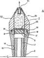
在图1~3中表示本发明的便携式喷出注入器具A的实施例1。如图1、2所示,该便携式喷出注入器具A的基本结构是,在前端部具有喷出嘴11的筒体1内装有活塞部5,通过推入杆7从筒体1后端部向喷出嘴11推入并移动上述活塞部5,而使药液或润滑剂(以下称作“药液等”)从喷出嘴11喷出。
筒体1包括:前端部截面呈圆形或椭圆形状的插入部2、从上述插入部2延伸设置的直线状纵长部3、和上述纵长部3的后端部的漏斗状部8。在筒体1内部,在从喷出嘴11到后端部的全长范围内形成有直径大致相同的空腔,并且,在插入部2中形成有装填部10,该装填部10收纳注入了药液等的凝胶状囊体4。The
如图2所示,插入部2形成为流线形,从前端向后端逐渐变粗,在最大位置上比纵长部3粗,在向人体的特定部位插入时,可以顺滑地进行而不会伴随着疼痛。此外,在该插入部2内,在从其前端到后端的一定范围内,形成有喷出药液等的喷出嘴11,在上述喷出嘴11的后端侧设置有切断部12(与喷出嘴一体成形的刀刃)。此外,在装填部10内,通过筒体1的漏斗状部8预先填充具有规定药液的凝胶状囊体4。另外,该装填部10的容积是由活塞部5决定的。As shown in Figure 2, the
在纵长部3上,在位于其内周壁上、且比用于对活塞位置进行定位的后述突起17(环状或是非环状突起)稍靠后端侧的位置上,形成有截面呈三角形的卡止突起19。上述卡止突起19,在以突起的顶部为顶角时,三角形的前端侧倾斜面的角度是80°左右(较大角度),而与此相对,后端侧倾斜面的角度是20°到30°左右(较小角度)。On the
活塞部5形成为在外周面上具有多个周槽6的厚板状,设置在与上述装填部10相邻接的位置上。如图2所示,在该活塞部5的周槽6内插入有由弹性部件(弹性体部件)构成的密封部件16,形成于筒体1的内周壁上的突起17(环状或非环状突起)嵌合在上述周槽下方的槽6中。即,该活塞部5通过密封部件16确保在推出药液等时筒体1的内周壁和活塞部5的外周面之间的流体密封性,通过突起17和槽6的卡合,在筒体1内对活塞部5进行定位。The
推入杆7如图1所示,由直线状筒体或杆体构成,并且,在其后端形成有扩张部9,在推压结束时所述扩张部9进入并卡合在上述漏斗状部8内。As shown in Figure 1, the push-in
此外,如图2所示,在推入杆7的外周面上设置有卡止突起14,所述卡止突起14处在与筒体1内壁的卡止突起19卡合的状态下。当以该卡止突起14的突起顶部为顶角时,三角形的前端侧倾斜面的角度是20°到30°左右的角度(较小角度),与此相对,后端侧倾斜面的角度是80°左右的角度(较大角度)。In addition, as shown in FIG. 2 , a locking
在此,将该推入杆7插入筒体1的纵长部3内并推入时,卡止突起14越过卡止突起19,在规定位置(从活塞部5的位置稍稍离开的位置)上得到支承。便携式喷出注入器具A在装填部10内填充有囊体4,如果如图3所示,向活塞部5进一步推入推入杆7,则活塞部推压囊体,由切断部12切入囊体4的上端,药液等从喷出嘴11喷出。Here, when the push-in
如图2所示,在该推入杆7上还设置有另一卡止突起14’,其设置在上述卡止突起14的后端侧,当上述卡止突起14’越过卡止突起19时,扩张部9进入到漏斗状部8内,推入结束。另外,卡止突起14’与卡止突起14为同样的形状,尽管在推入推入杆7时,卡止突起14’可以越过卡止突起19,但是一旦卡止突起14’通过了卡止突起19,则由于卡止突起14’和卡止突起19的卡止,推入杆7便很难从筒体1拔出或者不能拔出。As shown in FIG. 2 , another locking
另外,作为用于该便携式喷出注入器具A的药剂,可以列举出润滑剂、清洗剂、麻醉剂等。In addition, examples of the medicine used in the portable ejection and injection device A include a lubricant, a cleaning agent, an anesthetic, and the like.
当使用该便携式喷出注入器具A时,可以直接向女性的性器官(阴道内)或人的肛门内注入药液等。其使用方法如下所述。When this portable ejection and injection device A is used, it is possible to directly inject a medicinal solution or the like into a female sexual organ (in the vagina) or a human anus. Its use is described below.
(1)首先,将筒体1的前端部分插入到女性的性器官或人的肛门内。由于该筒体1的前端部分为前端较细的流线形,所以插入时很少伴随疼痛。此后,用食指和中指夹住筒体1,用拇指入推入杆7。于是推入杆7的前端部到达活塞部5,活塞部5被推出到前端侧,突起17和槽6的卡合被解除。(1) First, the front end portion of the
(2)当从上述(1)的状态进一步推入推入杆7时,填充了药液等的囊体4与活塞部5一起被推出到前端侧,通过切断部12将囊体4的前端侧切断。(2) When the pushing
(3)当从上述(2)的状态进一步推入推入杆7时,药液等从喷出嘴11喷出(包括射出)。(3) When the
(4)继续上述(3)的状态,扩张部9进入漏斗状部8内而结束推入杆7的推入时,填充在囊体4内的药液等几乎都从喷出嘴11喷出,同时卡止突起14’通过卡止突起19。于是,通过卡止突起14’和卡止突起19的卡止,推入杆7变得很难从筒体1拔出或者不能拔出。即,便携式喷出注入器具A不能再次使用。因而不会导致疾病的感染,还很卫生。(4) Continuing the state of above-mentioned (3), when the
(5)另外,也可以将药液等向女性性器官或人的肛门喷出,而对该部位进行清洗。(5) In addition, the liquid medicine etc. may be sprayed toward the female sex organ or the anus of a person to wash the part.
根据上述内容显然可知,利用该便携式喷出注入器具A,可以将药液等向女性的性器官或人的肛门喷出以便清洗该部位,根据需要还可直接注入到内部。It is obvious from the above that, using the portable spraying and injecting device A, the liquid medicine can be sprayed to the sexual organs of women or the anus of a person to clean the parts, and can be directly injected into the interior if necessary.
此外,在该便携式喷出注入器具A中,由于如图2所示采用了在装填部10内填充凝胶状囊体4的结构,所以可以防止药液等的泄漏。而且,在该便携式喷出注入器具A中,推入杆7和活塞部5相互分离,通过突起17和槽6来卡止活塞部5,所以即使推入杆7发生了移动,也可防止药液等的泄漏。在实施例2、3中也同样具有该优异的作用效果。In addition, in this portable ejection and injection device A, since the
实施例2的便携式喷出注入器具A具有与实施例1基本上相同的结构,如图4和图5所示,仅活塞部5和推入杆7的结构不相同。The portable ejection and injection device A of the second embodiment has basically the same structure as that of the first embodiment, as shown in FIG. 4 and FIG. 5 , only the structures of the
即,在该便携式喷出注入器具A中,在活塞部5的下端面(后端面)中央形成有凹部5’,在推入杆7的上端面上设置有与上述凹部5’相嵌合的突出部7’。在向装填部10装填药液等时,该突出部7’如注射器的把手那样发挥作用,可以装填规定量的药液等,使活塞部5位于规定的位置。在装填药液等之后,若活塞部5使推入杆7稍稍歪斜,则成为相互分离的状态。另外,也可以在凹部5’和突出部7’上分别形成螺纹部,以使两者螺纹结合。That is, in this portable ejection injection tool A, a recess 5' is formed in the center of the lower end face (rear end face) of the
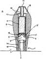
实施例3的便携式喷出注入器具A具有与实施例1基本上相同的结构,如图6所示,不同点仅在于,喷出嘴11不具有切断部12。The portable spraying and injecting tool A of Example 3 has basically the same structure as that of Example 1, as shown in FIG.
在该便携式喷出注入器具A中,装填部10由活塞部5限定而决定规定的容积,药液等向装填部10的填充,可以通过在不密封喷出嘴11的状态下向筒体1内插入一定量,而利用活塞部5和推入杆7进行填充,或者向筒体的空腔内插入其他带销针注入器而进行填充。In this portable spraying and injecting device A, the filling
如上所述将药液等填充在装填部10内后,如果如图6所示使推入杆7抵接在活塞部5上并以规定的力推入,则药液等经喷出嘴11射出。After filling the liquid medicine and the like in the
实施例4的便携式喷出注入器具A与实施例1基本上相同,如图7所示,不同点在于:分割成插入部2和纵长部3两个部分,通过螺纹结合使两者一体化而构成筒体1,而且,将插入部2形成为圆柱状。即,在该实施例4中,插入部2是由形成为帽状的帽部20构成的,在帽部20的后端内侧形成有阴螺纹部18,在纵长部3的前端外侧形成有阳螺纹部24。The portable ejection injection device A of
如图7所示,帽部20的后端部由隔膜部件23密闭,在前端中央形成有以规定深度延长的喷出嘴21,并且,形成有与上述喷出嘴21相连通的装填部10。另外,也可以在将药液等填充在装填部10内后,用粘接带或帽密封住喷出嘴21的流出口。As shown in FIG. 7, the rear end portion of the
如图7所示,纵长部3将活塞部5定位于最前端部,其他是与实施例1相同的结构。As shown in FIG. 7 , the
通过作成上述结构,可以根据喜好和使用目的等使用多种形状的帽部20。例如,除了图7中所示的正面观察呈四边形(圆筒形状)的帽部,还可以是图8中所示的上部前端侧为半球状的帽部、图9中所示的三角形状(圆锥状)的帽部、图10中所示的圆锥台形状的帽部。By making the above-mentioned structure, the
根据该便携式喷出注入器具A,通过向前端侧推入推入杆7,可以破坏隔膜部件23而将药液等经喷出嘴21喷出(包括射出)。According to this portable ejection and injection device A, by pushing the push-in
在实施例4的便携式喷出注入器具A中,药液等填充在帽部20内,所述帽部20的装填部10后端敞开部由隔膜部件23密闭,且喷出嘴21由带密封,若将该帽部与推入杆7等分开携带,则基本上可以完全防止药液等的泄漏。In the portable spraying and injecting device A of
该实施例5的便携式喷出注入器具A具有与实施例1基本上相同的结构,但如图11和图12所示,在活塞部5的中央部设置有凹部5’。即,在活塞部5的下表面中央形成凹部5’,从而形成得较薄。活塞部5可以用合成树脂、橡胶、弹性体等形成。The portable ejection and injection device A of the fifth embodiment has basically the same structure as that of the first embodiment, but as shown in FIGS. That is, the concave portion 5' is formed in the center of the lower surface of the
根据该便携式喷出注入器具A,一旦推入活塞部5,便不能再次使用。这是因为,即使从喷出嘴11插入销针等而想要将活塞部5推回,由于中央部形成得较薄而会导致开孔,从而不能推回。According to this portable ejection and injection tool A, once the
另外,如图2、图11、图12所示,由于从推入杆的上端到下端作成中空的,所以从喷出嘴11插入的销针等会通过活塞部5,然后到达推入杆的中空部分,所以不能用上述销针等将推入杆7推出到使用前的位置。即,该便携式喷出注入器具A不能再次使用,因而不会引起疾病感染,很卫生。In addition, as shown in Fig. 2, Fig. 11, and Fig. 12, since the upper end to the lower end of the push-in rod is made hollow, the pin inserted from the
本实施例6的便携式喷出注入器具A基本上与上述实施例1同样,但如图13~图15所示设计成,在通过推入杆7将活塞部5推入到喷出嘴11或其附近后再拔出推入杆7时,活塞部5会因与筒体1的内壁卡止而残留在上述喷出嘴11或其附近。为此,活塞部5、推入杆7以及筒体1的内壁面作成为以下的结构。The portable ejection and injection device A of the
如图13所示,活塞部5是下部敞开的帽状部分,在敞开部附近的内周部上设置有卡止突起50,在外周部上设置有卡止突起51。As shown in FIG. 13 , the
如图14所示,在筒体1的内周壁上设置有凹部100,当活塞部5移动到装填部10的最前端位置(喷出嘴11或其附近)时,卡止突起51嵌入在该凹部100中。As shown in FIG. 14, a
如图13~图15所示,在推入杆7的前端侧具备:承接部71,承接活塞部5的敞开端侧;活塞支承部70,在上述承接部71上延伸设置,上述活塞支承部70包括前端侧的头部72、和与该头部72的最大直径相比直径较细的颈部73。As shown in Figures 13 to 15, the front end side of the
在此,如图13所示,上述帽状活塞部5覆盖着从头部72到颈部73的部分,头部72推开卡止突起50而强制嵌入。因而,活塞部5不会不慎从推入杆7脱离。另外,在该便携式喷出注入器具A中,将头部72和卡止突起50的卡止力设定为,小于卡止突起51和凹部100的构成壁之间的卡止力。Here, as shown in FIG. 13 , the cap-shaped
因而,根据该便携式喷出注入器具A,如图14所示,在推入推入杆7时,活塞部5被推入到喷出嘴11或其附近,如图15所示,在拔出推入杆7时,活塞部5残留在喷出嘴11或其附近。即,该便携式喷出注入器具A不能再次使用,所以不会引起疾病的感染,很卫生。Therefore, according to this portable ejection and injection device A, as shown in FIG. When the
在上述实施例1~6中,在筒体1的前端设置有喷出嘴11、21,但是作为其他实施方式,也可将上述喷出嘴设成穿设于筒体1的前端壁面上的孔。In the above-mentioned
接下来,在实施例7~15中说明下述的便携式喷出注入器具A,其在携带时不会流出药液(主要是凝胶状物质),能将药液向女性的性器官或人的肛门喷出(包括射出)以洗净该部位,并可以根据需要直接注入到内部。Next, in Examples 7 to 15, the following portable spraying and injecting device A will be described, which does not flow out the liquid medicine (mainly a gel-like substance) when it is carried, and can inject the liquid medicine to the sexual organs of women or human organs. Anal squirt (including cumshot) to wash the area and can be injected directly inside if desired.
如图16所示,实施例7的便携式喷出注入器具A包括:筒体1,具有形成于前端的喷出嘴11和收纳药液的装填部10;活塞部5,封闭填充在上述筒体1的内部即装填部10中的药液;推入杆7,与上述活塞部5一体成形;帽120,封堵上述喷出嘴11。As shown in Fig. 16, the portable ejection and injection device A of
筒体1是由对人体无害的(孩子舔舐或放入嘴中也无害)ABS树脂等构成的筒状体,前端形状为直径从前端面起逐渐扩大、之后又逐渐缩小的形状。在此,在该筒体1前端部分的形状中,前端面的直径是8mm,从前端面到最大直径处、即直径15mm处的第1区域E1的长度为15mm,从第1区域E1的端部到直径缩小至12mm处的第2区域E2的长度为20mm,全长设定为90mm左右,前端面和外周面相交的部分被加工得很平滑。The
如图16所示,活塞部5是由ABS树脂制成(也可是橡胶制成)厚圆板形成的,在其外周面上,隔开间隔地周向设置有两个O形环(密封部件)116。如图16的双点划线所示,该活塞部5能在通过周向设置的O形环116将筒体1内维持在外周气密状态下的同时,进行移动。As shown in Fig. 16, the
推入杆7是在使轴心与活塞部5相一致的状态下、与该活塞部5一体成形的ABS树脂制的部件,其直径设定为比筒体1的孔稍小。另外,在最大限度地推入该推入杆7时,位于其后端部的扩张部(圆锥台部)9嵌入到位于筒体1的后端部的漏斗状部8内,并且,借助活塞部5,将装填部10内的几乎全部药液从喷出嘴11推出(喷出)到外部。The
如图16所示,帽120设定为紧贴地包覆第1区域E1部分的形状,在安装在筒体1上的状态下,从底面突出的轴部40嵌入到喷出嘴11内。As shown in FIG. 16 , the
该便携式药液喷出注入器具A,从其大小来说,可放入包中而挪动多支。因为帽120设定成紧贴地包覆筒体1的第1区域E1部分的形状,并且在安装在筒体1上的状态下,从底面突出的轴部40嵌入到喷出嘴11内,所以,在挪动时不会发生药液的不慎流出。即,不会有携带时药液流出而弄脏包内部的问题。This portable liquid medicine ejection and injection device A can be put into a bag to move multiple pieces in terms of its size. Since the
此外,该便携式药液喷出注入器具A,通过用食指和中指夹持筒体1的后端部分并用拇指推入推入杆7,可使药液从喷出嘴11喷出。因而,向作为人体特定部位的女性性器官或人的肛门喷出(包括射出)药液而对该部位进行清洗、或根据需要直接注入到内部的操作非常简单。In addition, in this portable liquid medicine injection device A, the liquid medicine can be sprayed from the
而且,在该便携式药液喷出注入器具A中,在筒体1的前端部分的形状中,前端面的直径是8mm,从前端面到最大直径处、即直径15mm处的第1区域E1的长度为15mm,从第1区域E 1的端部到直径缩小至12mm处的第2区域E 2的长度为20mm,全长设定为90mm左右,前端面和外周面相交的部分被加工得很平滑,由此在向阴道内或肛门内插入中不会产生疼痛,即使从阴道壁或肛门壁作用压力,也很难不慎脱落。在第1区域E1、第2区域E2中,上述形状呈截面圆形,但是也可以作成稍微扁平(椭圆)的形状。In addition, in this portable liquid medicine ejection and injection device A, in the shape of the front end portion of the
作为帽120,也可以是覆盖喷出嘴11的敞开部的粘接带或粘接密封件。The
图17是本发明实施例8的便携式药液喷出注入器具A的分解图,将筒体1剖开表示。Fig. 17 is an exploded view of the portable liquid medicine ejection and injection device A according to the eighth embodiment of the present invention, showing the
该便携式药液喷出注入器具A,采用将药液填充在囊体4中的形式,并且,在使用时(药液喷出操作时),通过设置在活塞部5的前端面上的销针112将囊体4刺破。因而,如果不将囊体4填充在筒体1内而是与便携式药液喷出注入器具A分开携带,则不会发生药液从喷出嘴11流出的情况。因为筒体1、推入杆3与实施例1完全相同,所以显然也具有其他效果。This portable liquid medicine spraying and injecting device A adopts the form in which the medicine liquid is filled in the
另外,也可不设置上述销针112,而将喷出嘴11的后端部作成尖的切断部12,通过该部分刺破囊体4。In addition, the above-mentioned pin 112 may not be provided, but the rear end portion of the
图18表示本发明实施例9的便携式药液喷出注入器具A的局部剖视图。该便携式药液喷出注入器具A用于实现与上述实施例7、8相同的目的,在活塞部5的外周面上形成有周槽116,并且在筒体1的内周壁上形成有嵌入到上述周槽116中的环状突起17,通过使两者嵌合,只要在推入杆7上不施加一定大小以上的推入力,活塞部5就不会移动。因而,即使封堵喷出嘴11的是粘接带或粘接密封件,也不易发生药液从喷出嘴11流出的情况。筒体1、推入杆7与实施例7完全相同,所以显然也具有其他效果。另外,也可以在活塞部侧设置环状突起,在筒体1的内周壁上设置上述突起所嵌入的周槽,并使两者嵌合。Fig. 18 is a partial cross-sectional view of a portable drug solution ejection and injection device A according to
图19是本发明实施例10的便携式药液喷出注入器具A的分解图,剖开表示筒体1。该便携式药液喷出注入器具A,在筒体1的的前端部形成有多个喷出嘴11,由此可使药液同时从喷出嘴11向广阔的区域喷出。另外,虽未图示,但在筒体1的前端部上覆盖着与实施例7同样的帽120。Fig. 19 is an exploded view of the portable liquid medicine spraying and injecting device A according to the tenth embodiment of the present invention, showing the
图20表示本发明实施例11的便携式药液喷出注入器具A的分解图。该便携式药液喷出注入器具A将筒体1作成透明或半透明的,并且在其外周面上以相等间隔形成有三条(多条)刻度线30,在筒体1内填充3次的量的药液。利用该器具,通过目视活塞部5的前端面侧的位置,能分3次使用,每次以大致准确的量使用一个刻度线部分的量(规定量)。另外,如果在推入杆7的外周面上以相等间隔形成3条刻度线,并以筒体1的后端和上述刻度线为基准进行使用,也可以得到同样的效果。Fig. 20 is an exploded view of a portable drug solution ejection and injection device A according to an eleventh embodiment of the present invention. In this portable liquid medicine injection device A, the
图21是本发明实施例12的便携式药液喷出注入器具A的分解图,剖开表示筒体1等。Fig. 21 is an exploded view of the portable liquid medicine ejection and injection device A according to the twelfth embodiment of the present invention, showing the
该便携式药液喷出注入器具A不是直接通过活塞部5将填充在装填部10内的药液推出,而是利用空气压力来推出药液,所述空气压力是通过经由推入杆7推入活塞部5而产生的。为此,在筒体1内设置有具有中央孔33的分隔壁32,通过活塞部5向喷出嘴11侧的移动,经中央孔33对装填部10内的药液作用加压空气力。This portable liquid medicine spraying and injecting device A does not directly push out the medicine liquid filled in the filling
图22表示本发明实施例13的便携式药液喷出注入器具A的剖视图。该便携式药液喷出注入器具A采用如下结构:将推入杆7作成筒状而设置药液填充通道15,使用时将气溶胶罐K内的药液填充到装填部10内。为此,在推入杆7的后端面上设置有凹部31,并具备在药液填充后堵塞上述凹部31的塞体(未图示),罐的喷出嘴N在外周气密状态下嵌入在所述凹部31中。另外,也可采用从喷出嘴11填充药液的结构。Fig. 22 is a cross-sectional view of a portable drug solution ejection and injection device A according to a thirteenth embodiment of the present invention. The portable liquid medicine spraying and injecting device A adopts the following structure: the
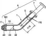
图23是本发明实施例14的便携式药液喷出注入器具A的剖视图。该便携式药液喷出注入器具A除了上述目的之外,还旨在使得向阴道内或肛门内注入药液的操作易于进行,从而在从筒体1的前端到中间的部分之中的任一处折曲。为此,在该实施例14中,与上述实施例6同样,不是直接通过活塞部5将填充在装填部10内的药液推出,而是利用经由推入杆7推入活塞部5而产生的空气压力来推出药液。即,在筒体1内设置有具有中央孔33的分隔壁32,通过活塞部5向喷出嘴11侧的移动,而经由中央孔33对装填部10内的药液作用加压空气力。Fig. 23 is a cross-sectional view of a portable liquid medicine ejection and injection device A according to a fourteenth embodiment of the present invention. In addition to the above-mentioned purpose, the portable liquid medicine spraying and injecting device A also aims to facilitate the operation of injecting liquid medicine into the vagina or anus, so that any part from the front end to the middle of the
另外,筒体1的折曲角度并不限于图23中所示的角度,可以适当决定。例如可以折曲成45°、90°等。In addition, the bending angle of the
图24表示发明实施例15的便携式药液喷出注入器具A的侧视图。该实施例15基本与图23相同,不同点仅在于,将该筒体1折弯成圆弧形,使得筒体1的前端侧部分和后端侧部分平行。Fig. 24 shows a side view of a portable liquid medicine ejection and injection device A according to
在上述实施例7~15中,活塞部5和推入杆7为一体,但是只要能借助推入杆7向喷出嘴11侧推入活塞部5,则两者也可构成为分体。In
下面,对在进行药液等的喷出或注入操作时使用方便性好的结构进行说明。Next, a structure that is easy to use when performing ejection or injection operations of a chemical solution or the like will be described.
如图25所示,包括:筒体1,具有形成于前端的喷出嘴11(喷出孔)、和收纳药液等的装填部10;活塞部5,封闭填充在上述筒体1的内部即装填部10内的药液等;推入杆7,与上述活塞部5一体成形;帽120,堵塞上述喷出嘴11;在距筒体1的前端50mm(20~100mm的范围内即可)的部分上折曲。而且,不是直接通过活塞部5将填充于装填部10内的药液等推出(喷出),而是利用经由推入杆7推入活塞部5而产生的加压了的空气压力,使药液等喷出。As shown in FIG. 25 , it includes: a
筒体1是由小孩舔舐也不会有害的ABS树脂等构成的筒状体,其形状是直径从前端面(直径8mm)起逐渐变大、之后变得恒定(直径15mm左右)的形状。此外,如图25所示,在筒体1内设置有具有中央孔33的分隔壁32,通过活塞部5向喷出嘴11侧的移动,经由中央孔33而对装填部10内的药液作用加压了的空气力。另外,在该筒体1中,前端面和外周面相交的角部被加工得很平滑,从而在插入人体时不会伴随有疼痛的产生。The
活塞部5由ABS树脂制(也可是橡胶制)的厚圆板形成,在其外周面上隔开间隔地周向设置有2个O形环(密封部件)116。如图25的双点划线所示,该活塞部5能在通过周向设置的O形环116而将筒体1内维持在外周气密状态下的同时,进行移动。The
如图25所示,推入杆7是在使轴心与上述活塞部5一致的状态下一体(也可以是分体)成形在该活塞部5上的ABS树脂制的部件,其直径设定成稍小于筒体1的孔。另外,在最大限度地推入该推入杆7时,在筒体1的折曲部近前停止。As shown in Figure 25, the push-in
帽120设定成紧贴地包覆筒体1的前端部分的形状,在安装在筒体1上的状态下,从底面突出的轴部40嵌入在喷出嘴11内。The
该便携式药液喷出注入器具A,从其大小来说,可放入包中而挪动多支。因为在帽120安装在筒体1上的状态下,从底面突出的轴部40嵌入到喷出嘴11内,所以,在挪动时不会发生药液的不慎流出。即,不会有携带时药液流出而弄脏包内部的问题。This portable liquid medicine ejection and injection device A can be put into a bag to move multiple pieces in terms of its size. Since the
此外,该便携式药液喷出注入器具A,通过用食指和中指夹持筒体1的后端部分并用拇指推入推入杆7,而可使药液从喷出嘴11喷出。此时,由于使筒体1倾斜折曲30°左右,所以易于利用药剂等进行清洗以及进行药剂等的注入操作。In addition, the portable liquid medicine spraying and injecting device A can spray the liquid medicine from the
图26表示本发明实施例17的便携式喷出注入器具A的剖视图。Fig. 26 is a cross-sectional view of a portable ejection and injection device A according to a seventeenth embodiment of the present invention.
该便携式喷出注入器具A用于实现与上述实施例16同样的目的,但在下述一点上不同于实施例16:如图26所示,能使推入杆7仿效筒体1的30°折曲形状而弹性地折弯或弯曲,直接通过上述推入杆7从喷出嘴11推出药液等。This portable ejection injection device A is used to achieve the same purpose as the above-mentioned
推入杆7可以用例如弹性合成树脂、橡胶、弹性体等形成的截面圆形的杆状体或两端封堵起来的管状体形成。The push-in
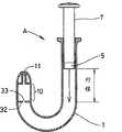
图27表示本发明实施例18的便携式喷出注入器具A的剖视图。该便携式喷出注入器具A用于实现与上述实施例16同样的目的,但是在实施例16中折曲或弯曲的角度是固定的,而与此相对,在该实施例18中,通过将该部分作成折皱部34,而可自由改变折曲或弯曲的角度。Fig. 27 is a cross-sectional view of a portable ejection and injection device A according to an eighteenth embodiment of the present invention. This portable ejection injection device A is used to achieve the same purpose as the above-mentioned
在此,在最大限度地推入了上述推入杆7的状态下,如图27所示,活塞部5在折皱部34的近前停止,利用筒体1内加压了的空气压力从喷出嘴11中喷出药液等。此外,上述折皱部34可保持变形后的形状。Here, in the state where the above-mentioned push-in
在上述便携式喷出注入器具A中,其形状是截面圆形,但是也可作成稍微扁平的形状(椭圆形状)。In the above-mentioned portable ejection and injection tool A, its shape is circular in cross section, but it may be made into a slightly flat shape (elliptical shape).
在上述便携式喷出注入器具A中,折曲角度是30°,但是并不限于此,可以作成30°~90°(例如45°或图28中所示的90°)。此外,也可以如图29所示弯曲成U字状。In the above-mentioned portable ejection and injection device A, the bending angle is 30°, but it is not limited thereto, and may be 30° to 90° (for example, 45° or 90° as shown in FIG. 28 ). Alternatively, it may be bent into a U-shape as shown in FIG. 29 .
作为帽120,也可以是覆盖喷出嘴11的敞开部的粘接带或粘接密封件等。As the
Claims (4)
Applications Claiming Priority (12)
| Application Number | Priority Date | Filing Date | Title |
|---|---|---|---|
| JP2003435256 | 2003-12-26 | ||
| JP2003-435256 | 2003-12-26 | ||
| JP2003-435270 | 2003-12-26 | ||
| JP2003435270 | 2003-12-26 | ||
| JP2004-013164 | 2004-01-21 | ||
| JP2004013164AJP2005204798A (en) | 2004-01-21 | 2004-01-21 | Portable medical fluid jetting and injecting tool |
| JP2004043573AJP2005205121A (en) | 2003-12-26 | 2004-02-19 | Portable spraying and injecting tool |
| JP2004043569AJP2005230285A (en) | 2004-02-19 | 2004-02-19 | Portable injection syringe |
| JP2004043578AJP4582391B2 (en) | 2003-12-26 | 2004-02-19 | Portable injection injector |
| JP2004-043578 | 2004-02-19 | ||
| JP2004-043569 | 2004-02-19 | ||
| JP2004-043573 | 2004-02-19 |
Related Parent Applications (1)
| Application Number | Title | Priority Date | Filing Date |
|---|---|---|---|
| CN200480039124ADivisionCN100591371C (en) | 2003-12-26 | 2004-12-24 | Portable ejection injector |
Publications (2)
| Publication Number | Publication Date |
|---|---|
| CN101785884A CN101785884A (en) | 2010-07-28 |
| CN101785884Btrue CN101785884B (en) | 2013-01-30 |
Family
ID=34812412
Family Applications (1)
| Application Number | Title | Priority Date | Filing Date |
|---|---|---|---|
| CN 200910263749Expired - Fee RelatedCN101785884B (en) | 2003-12-26 | 2004-12-24 | Portable ejection and injection device |
Country Status (4)
| Country | Link |
|---|---|
| EP (2) | EP1702634A4 (en) |
| CN (1) | CN101785884B (en) |
| MY (1) | MY144107A (en) |
| WO (1) | WO2005070479A1 (en) |
Families Citing this family (14)
| Publication number | Priority date | Publication date | Assignee | Title |
|---|---|---|---|---|
| DE102010013543B3 (en)* | 2010-03-26 | 2011-06-30 | Ing. Erich Pfeiffer GmbH, 78315 | Discharge device for liquids |
| PL3777834T3 (en)* | 2012-06-01 | 2022-05-30 | Novartis Ag | Syringe |
| WO2013191317A1 (en)* | 2012-06-22 | 2013-12-27 | (주)웻트러스트 코리아 | Device for injecting liquid into body, comprising separable sealing member |
| CN103519779A (en)* | 2012-07-03 | 2014-01-22 | 陈远光 | Kidney-shaped elastic rectoscope |
| US9272123B2 (en) | 2013-12-16 | 2016-03-01 | Esther Gallant | Device and method for inserting lubricating capsule |
| MC200184B1 (en)* | 2017-02-07 | 2017-08-30 | Stefano Mastrantonio | SELF-RETAINING CANNULA WITH GUARANTEE STAMP |
| BR102017016174B1 (en)* | 2017-07-27 | 2020-08-11 | Doris Maria Hexsel | WRAPPING DEVICE FOR DISPENSING TOPICAL PRODUCTS FOR ORAL, VULVAR AND ANAL USE, COUPLABLE TO PORTABLE APPLICATOR FOR VAGINAL AND RECTAL USES |
| GB201815552D0 (en)* | 2018-09-24 | 2018-11-07 | Norton Healthcare Ltd | Injection device |
| GB201815551D0 (en) | 2018-09-24 | 2018-11-07 | Norton Healthcare Ltd | Injection device |
| JP7094392B2 (en)* | 2019-04-30 | 2022-07-01 | ヒュオンス メディカル カンパニー リミテッド | Internal drug injection injection device |
| CN110314273A (en)* | 2019-07-09 | 2019-10-11 | 自贡市第四人民医院(自贡市急救中心) | A kind of supra-aural intranasal medicator and medication |
| KR102114336B1 (en)* | 2019-11-22 | 2020-05-28 | 정화 | Automatic cleaning and washing device for material administration in the body |
| CN112386761B (en)* | 2020-11-24 | 2022-08-30 | 乐山市人民医院 | Disposable enema device |
| US20250144311A1 (en)* | 2023-11-03 | 2025-05-08 | Munchkin, Inc. | Nipple shield flush syringe and storage sterilizing case |
Citations (2)
| Publication number | Priority date | Publication date | Assignee | Title |
|---|---|---|---|---|
| CN1078647A (en)* | 1991-12-03 | 1993-11-24 | 格拉克索公司 | Device |
| CN2210679Y (en)* | 1994-11-01 | 1995-10-25 | 深圳蛇口大源投资有限公司 | Device for introducing medicine in cavities |
Family Cites Families (10)
| Publication number | Priority date | Publication date | Assignee | Title |
|---|---|---|---|---|
| US3506008A (en)* | 1968-03-25 | 1970-04-14 | Ortho Pharma Corp | Medical applicator |
| JPS59100433U (en)* | 1982-12-24 | 1984-07-06 | 株式会社トツプ | Syringe with cartridge inserted |
| JPS60227773A (en)* | 1983-12-22 | 1985-11-13 | 山田 靖幸 | Ultra-small portable syringe |
| US4636202A (en)* | 1984-07-27 | 1987-01-13 | Syntex (U.S.A.) Inc. | Medicament applicator with plunger assembly and automatically-openable closure therefor |
| ZA932947B (en)* | 1992-04-28 | 1993-10-27 | Schering Plough Healthcare | Applicator for semisolid medications |
| CA2171627C (en)* | 1993-09-17 | 2006-01-31 | Victoria A. O'neill | Rectally-administered, epileptic-seizure-inhibiting composition |
| JP2595798Y2 (en)* | 1993-12-28 | 1999-06-02 | 共同印刷株式会社 | Injector / pourer |
| US5637087A (en)* | 1995-03-22 | 1997-06-10 | Abbott Laboratories | Prefilled, two-constituent syringe |
| JP2001187151A (en) | 1999-12-28 | 2001-07-10 | Sachio Uehara | Disposable lubricating liquid injection device |
| JP2003325663A (en)* | 2002-05-09 | 2003-11-18 | Masayuki Kuno | Cartridge injector |
- 2004
- 2004-12-24MYMYPI20045357patent/MY144107A/enunknown
- 2004-12-24EPEP04807792Apatent/EP1702634A4/ennot_activeWithdrawn
- 2004-12-24WOPCT/JP2004/019436patent/WO2005070479A1/enactiveApplication Filing
- 2004-12-24CNCN 200910263749patent/CN101785884B/ennot_activeExpired - Fee Related
- 2004-12-24EPEP10013291.9Apatent/EP2301599B1/ennot_activeExpired - Lifetime
Patent Citations (2)
| Publication number | Priority date | Publication date | Assignee | Title |
|---|---|---|---|---|
| CN1078647A (en)* | 1991-12-03 | 1993-11-24 | 格拉克索公司 | Device |
| CN2210679Y (en)* | 1994-11-01 | 1995-10-25 | 深圳蛇口大源投资有限公司 | Device for introducing medicine in cavities |
Also Published As
| Publication number | Publication date |
|---|---|
| EP1702634A1 (en) | 2006-09-20 |
| EP2301599A1 (en) | 2011-03-30 |
| MY144107A (en) | 2011-08-15 |
| WO2005070479A1 (en) | 2005-08-04 |
| CN101785884A (en) | 2010-07-28 |
| EP1702634A4 (en) | 2010-08-04 |
| HK1146911A1 (en) | 2011-07-22 |
| EP2301599B1 (en) | 2014-04-16 |
| HK1102400A1 (en) | 2007-11-23 |
Similar Documents
| Publication | Publication Date | Title |
|---|---|---|
| CN101785884B (en) | Portable ejection and injection device | |
| JP4319357B2 (en) | Medication applicator | |
| JP4632510B2 (en) | Nose feeding device with spray nozzle | |
| US5213566A (en) | Prefilled suppository applicator | |
| US5531703A (en) | Applicator for semisolid medications | |
| US5330427A (en) | Prefilled suppository applicator | |
| KR101771894B1 (en) | Drug Infuser for Internal Diseases | |
| JP2009530055A (en) | Intravaginal drug applicator | |
| GB2431356A (en) | Disposable needle-less syringe | |
| KR101956671B1 (en) | Apparatus for inserting liquid in body having structure in which pushing or retraction of the plunger is restricted | |
| JP3035448U (en) | Periodontal pocket drug injector | |
| CN100591371C (en) | Portable ejection injector | |
| JP4582391B2 (en) | Portable injection injector | |
| KR101467596B1 (en) | Connection structure between container and supply pipe, container and supply pipe | |
| JP4964976B2 (en) | Portable injection injector | |
| KR100979592B1 (en) | Nasal cleaning chemical spray device | |
| HK1146911B (en) | Portable jetting/filling device | |
| HK1102400B (en) | Portable jetting/filling device | |
| CN103619376A (en) | Body fluid injection device with detachable seal | |
| JP3129241U (en) | Enema unit | |
| JP7275425B2 (en) | drug injection device | |
| JP2005204798A (en) | Portable medical fluid jetting and injecting tool | |
| JP7389308B2 (en) | drug injection device | |
| KR101830148B1 (en) | Apparatus for injecting liquid in body of wrinkle pump structure | |
| JP2005205121A (en) | Portable spraying and injecting tool |
Legal Events
| Date | Code | Title | Description |
|---|---|---|---|
| C06 | Publication | ||
| PB01 | Publication | ||
| C10 | Entry into substantive examination | ||
| SE01 | Entry into force of request for substantive examination | ||
| REG | Reference to a national code | Ref country code:HK Ref legal event code:DE Ref document number:1146911 Country of ref document:HK | |
| C14 | Grant of patent or utility model | ||
| GR01 | Patent grant | ||
| REG | Reference to a national code | Ref country code:HK Ref legal event code:GR Ref document number:1146911 Country of ref document:HK | |
| CF01 | Termination of patent right due to non-payment of annual fee | ||
| CF01 | Termination of patent right due to non-payment of annual fee | Granted publication date:20130130 |