CN101782639B - Method, device and system for calibrating a positioning device - Google Patents
Method, device and system for calibrating a positioning deviceDownload PDFInfo
- Publication number
- CN101782639B CN101782639BCN2009100020771ACN200910002077ACN101782639BCN 101782639 BCN101782639 BCN 101782639BCN 2009100020771 ACN2009100020771 ACN 2009100020771ACN 200910002077 ACN200910002077 ACN 200910002077ACN 101782639 BCN101782639 BCN 101782639B
- Authority
- CN
- China
- Prior art keywords
- positioning device
- space
- interest
- region
- feature points
- Prior art date
- Legal status (The legal status is an assumption and is not a legal conclusion. Google has not performed a legal analysis and makes no representation as to the accuracy of the status listed.)
- Expired - Fee Related
Links
Images


Classifications
- G—PHYSICS
- G01—MEASURING; TESTING
- G01S—RADIO DIRECTION-FINDING; RADIO NAVIGATION; DETERMINING DISTANCE OR VELOCITY BY USE OF RADIO WAVES; LOCATING OR PRESENCE-DETECTING BY USE OF THE REFLECTION OR RERADIATION OF RADIO WAVES; ANALOGOUS ARRANGEMENTS USING OTHER WAVES
- G01S5/00—Position-fixing by co-ordinating two or more direction or position line determinations; Position-fixing by co-ordinating two or more distance determinations
- G01S5/02—Position-fixing by co-ordinating two or more direction or position line determinations; Position-fixing by co-ordinating two or more distance determinations using radio waves
- G01S5/0205—Details
- G01S5/021—Calibration, monitoring or correction
Landscapes
- Physics & Mathematics (AREA)
- Engineering & Computer Science (AREA)
- General Physics & Mathematics (AREA)
- Radar, Positioning & Navigation (AREA)
- Remote Sensing (AREA)
- Position Fixing By Use Of Radio Waves (AREA)
- Measurement Of Velocity Or Position Using Acoustic Or Ultrasonic Waves (AREA)
Abstract
Description
Translated fromChinese技术领域technical field
本发明涉及定位技术领域,具体而言,涉及一种用于对定位设备进行标定的方法、设备和系统以及一种用于表征空间中的关注区域的方法、设备和系统。The present invention relates to the field of positioning technology, in particular, to a method, device and system for calibrating a positioning device, and a method, device and system for characterizing an area of interest in space.
背景技术Background technique
位置信息是一种可用来提取用户与环境之间的地理关系从而进一步理解和获知用户行为的基本上下文。方位感知应用的重要性和前景已经使得设计和实施出了用于提供位置信息的系统。目前,已经开发出了一些高精度室内定位系统(Ha-IPS:High Accuracy IndoorPositioning System),用于在不同应用场合对人员和财产进行实时精确跟踪。这些应用场合可包括多种环境,例如办公室、健康护理机构、煤矿、地铁、智能建筑物以及餐馆等等。Location information is a basic context that can be used to extract the geographic relationship between the user and the environment to further understand and learn user behavior. The importance and promise of position-aware applications has led to the design and implementation of systems for providing location information. At present, some high-precision indoor positioning systems (Ha-IPS: High Accuracy IndoorPositioning System) have been developed for real-time and precise tracking of people and property in different applications. These applications can include environments such as offices, healthcare facilities, coal mines, subways, smart buildings, and restaurants, among others.
目前,这些Ha-IPS通常是基于超声波或超宽带无线电的。它们的共同特征是能够提供厘米级别的定位精度。在此类Ha-IPS的一些应用场合,需要在相关的环境中布设和标定一些定位设备来监视移动目标在特定关注区域(AOI:Areas of Interest)中的位置。通常,定位系统,例如Ha-IPS,能够对这些移动目标的位置进行实时跟踪从而提供一些特定的基于位置的服务。例如,在办公室环境中,当布设例如Ha-IPS的定位系统时,其可以跟踪终端或雇员的位置。由此,可以设计出基于位置的访问规则,以便定义特定的“安全区域”。例如,只有在此安全区域之内才允许对机密信息的访问,而一旦超出该安全区域或处于该安全区域之外,则禁止对该机密信息的任何访问。以上所说的安全区域可以是一个房间、一部分工作区域,甚至可以是一张桌子。Currently, these Ha-IPS are usually based on ultrasound or ultra-wideband radio. Their common feature is the ability to provide centimeter-level positioning accuracy. In some applications of this type of Ha-IPS, it is necessary to deploy and calibrate some positioning devices in related environments to monitor the position of moving targets in specific areas of interest (AOI: Areas of Interest). Usually, a positioning system, such as Ha-IPS, can track the positions of these moving targets in real time so as to provide some specific location-based services. For example, in an office environment, when a positioning system such as Ha-IPS is deployed, it can track the location of terminals or employees. From this, location-based access rules can be designed to define specific "safe areas." For example, access to confidential information is allowed only within the security area, and any access to the confidential information is prohibited once the security area is exceeded or outside the security area. The safe area mentioned above can be a room, part of a work area, or even a desk.
迄今为止已经开发出多种Ha-IPS,用于提供用户和环境之间的地理关系。在这些Ha-IPS中,定位以及地理关系确定过程可以被归纳为如下三个阶段:Various Ha-IPS have been developed so far for providing the geographic relationship between the user and the environment. In these Ha-IPS, the positioning and geographic relationship determination process can be summarized into the following three stages:
1.Ha-IPS设置阶段。该阶段一般包括以下步骤:1. Ha-IPS setup stage. This stage generally includes the following steps:
1)对基准点的位置进行标定。基准点的位置是指信标或定位设备的位置。当计算目标点的位置时,必须事先知道基准点或者定位设备的位置并将这些位置信息用作定位算法中的计算基准。1) Calibrate the position of the reference point. The location of the reference point refers to the location of the beacon or positioning device. When calculating the position of the target point, it is necessary to know the position of the reference point or the positioning device in advance and use this position information as the calculation reference in the positioning algorithm.
2)配置基准空间的尺寸。基准空间是指目标在其中移动的空间。基准空间例如可以是房间、办公室等等。为了获知目标与环境之间的地理关系,必须知道基准空间的尺寸。2) Configure the size of the reference space. The reference space is the space in which the target moves. The reference space may be, for example, a room, an office, and the like. In order to know the geographic relationship between the target and the environment, the size of the reference space must be known.
3)表征关注区域。关注区域是指用户出于特定的应用需求(例如安全目的)而表征了的地理区域。关注区域位于基准空间中。例如,在“安全桌面”的应用中,该桌面被定义为关注区域。只有在此关注区域内才允许对机密信息的访问,而一旦超出该关注区域或处于该关注区域之外,则禁止对该机密信息的任何访问。3) Characterize the region of interest. An area of interest refers to a geographic area characterized by a user for specific application requirements (eg, security purposes). The region of interest is in the datum space. For example, in the application of "secure desktop", the desktop is defined as the area of interest. Access to confidential information is permitted only within this area of concern, and any access to that confidential information is prohibited once outside or outside of this area of concern.
在Ha-IPS设置阶段,由于基准点标定中的误差将会被移植到目标定位处理中,因此需要标定足够地精确。此外,由于通常情况下定位设备一般布设在屋顶,所以特别希望能够以较少的人工来实现该标定过程。另外,由于测量实际环境通常需要很多人工,因此特别需要一种准确、快速和自动的基准空间配置方法。During the Ha-IPS setup phase, the calibration needs to be accurate enough since the errors in the fiducial calibration will be transferred to the target positioning process. In addition, since the positioning equipment is generally arranged on the roof, it is particularly hoped that the calibration process can be realized with less labor. In addition, because measuring the actual environment usually requires a lot of labor, an accurate, fast and automatic method for configuring the reference space is especially needed.
2.Ha-IPS在线定位阶段。在该阶段中,根据所标定的基准点的坐标以及所测得的目标的距离来计算目标点的实时位置。2. Ha-IPS online positioning stage. In this stage, the real-time position of the target point is calculated according to the coordinates of the marked reference point and the measured distance of the target.
3.地理关系推断阶段。在该阶段中,根据在上面的第二阶段所计算的目标点的实时位置以及基准空间和关注区域(AOI)的定义来推断目标与基准空间以及关注区域的关系。在该过程中,关注区域通常是通过手动方式来进行表征的,这涉及了很多的测量和记录方面的努力。3. Geographic relationship inference stage. In this phase, the relationship of the target to the reference space and the AOI is inferred based on the real-time position of the target point calculated in the second stage above and the definition of the reference space and the area of interest (AOI). In this process, regions of interest are typically characterized manually, which involves extensive measurement and documentation efforts.
可以看出,现有Ha-IPS的共同缺陷在于他们的配置、标定以及表征等都需要大量的人工努力。因此,现有Ha-IPS的使用并不方便,也不符合用户友好的需要。It can be seen that the common defect of existing Ha-IPS is that their configuration, calibration, and characterization require a lot of manual effort. Therefore, the existing Ha-IPS is inconvenient to use and does not meet user-friendliness requirements.
这样,本领域特别需要提供一种对定位设备自动进行配置和标定的技术方案,也特别需要一种自动对空间的关注区域进行表征技术方案。In this way, the art particularly needs to provide a technical solution for automatically configuring and calibrating a positioning device, and also particularly needs a technical solution for automatically characterizing a spatial region of interest.
发明内容Contents of the invention
本发明的目的之一是提供一种自动对定位设备进行配置和标定的技术方案。One of the objectives of the present invention is to provide a technical solution for automatically configuring and calibrating a positioning device.
本发明的另一目的是提供一种自动表征空间中的关注区域的技术方案。Another object of the present invention is to provide a technical solution for automatically characterizing a region of interest in space.
根据本发明的第一方面,提供一种系统,该系统可以包括:能够发射测距信号的标签,放置在空间中作为空间特征点的位置点处;位于空间中的定位设备,被配置为根据来自标签的测距信号获取空间特征点相对于定位设备的相对坐标;以及服务器,被配置为根据相对坐标来确定定位设备在空间中的位置参数,从而标定定位设备。According to the first aspect of the present invention, there is provided a system, which may include: a tag capable of transmitting a ranging signal, placed at a location point in space as a spatial feature point; a positioning device located in space, configured to The ranging signal from the tag acquires the relative coordinates of the spatial feature points relative to the positioning device; and the server is configured to determine the position parameters of the positioning device in space according to the relative coordinates, so as to calibrate the positioning device.
根据本发明的第二方面,提供一种系统,该系统可以包括:能够发射测距信号的标签,放置于空间中的位置点处;已标定的第一定位设备,被配置为根据来自标签的测距信号获取位置点在空间中的绝对坐标;第二定位设备,被配置为根据来自标签的测距信号获取位置点相对于第二定位设备的相对坐标;以及服务器,被配置为根据绝对坐标和相对坐标来确定第二定位设备在空间中的位置参数,从而标定第二定位设备,其中位置点处于第一定位设备和第二定位设备的重叠覆盖区域中。According to a second aspect of the present invention, a system is provided, which may include: a tag capable of transmitting ranging signals, placed at a position point in space; a marked first positioning device configured to The ranging signal acquires the absolute coordinates of the position point in space; the second positioning device is configured to acquire the relative coordinates of the position point relative to the second positioning device according to the ranging signal from the tag; and the server is configured to obtain the relative coordinates of the position point relative to the second positioning device according to the absolute coordinates and relative coordinates to determine the position parameters of the second positioning device in space, so as to calibrate the second positioning device, wherein the position point is in the overlapping coverage area of the first positioning device and the second positioning device.
根据本发明第三方面,提供一种系统,该系统可以包括:能够发射测距信号的标签,放置在能够表征空间中的关注区域的关注区域特征点处;空间中的定位设备,被配置为根据来自标签的测距信号获取关注区域特征点的位置参数;以及服务器,被配置为根据关注区域特征点的位置参数来表征关注区域。According to a third aspect of the present invention, a system is provided, which may include: a tag capable of transmitting a ranging signal, placed at a feature point of an area of interest that can represent an area of interest in space; a positioning device in space configured to Acquiring location parameters of the feature points of the region of interest according to ranging signals from the tags; and a server configured to characterize the region of interest according to the location parameters of the feature points of the region of interest.
根据本发明第四方面,提供一种用于对空间中的定位设备进行标定的方法,其中,该空间中的位置点被选择作为空间特征点。该方法可以包括:接收空间特征点相对于定位设备的相对坐标;以及根据相对坐标来确定定位设备在空间中的位置参数,从而标定定位设备。According to a fourth aspect of the present invention, a method for calibrating a positioning device in a space is provided, wherein position points in the space are selected as spatial feature points. The method may include: receiving relative coordinates of spatial feature points relative to the positioning device; and determining position parameters of the positioning device in space according to the relative coordinates, so as to calibrate the positioning device.
根据本发明第五方面,提供一种用于对定位设备进行标定的方法。该方法可以包括:接收位置点在空间中的绝对坐标以及位置点相对于定位设备的相对坐标;以及根据绝对坐标和相对坐标来确定定位设备在所述空间中的位置参数,从而标定定位设备。According to a fifth aspect of the present invention, a method for calibrating a positioning device is provided. The method may include: receiving absolute coordinates of the location point in space and relative coordinates of the location point relative to the positioning device; and determining position parameters of the positioning device in the space according to the absolute coordinates and the relative coordinates, thereby calibrating the positioning device.
根据本发明第六方面,提供一种用于表征空间中的关注区域的方法。该方法可以包括:接收能够表征关注区域的关注区域特征点的位置参数,其中所述位置参数是利用布置在空间中的定位设备获得的;以及根据位置参数,来表征所述关注区域。According to a sixth aspect of the invention there is provided a method for characterizing a region of interest in space. The method may include: receiving location parameters of feature points of the region of interest capable of characterizing the region of interest, wherein the location parameters are obtained using a positioning device arranged in space; and characterizing the region of interest according to the location parameters.
根据本发明第七方面,提供一种用于对布置在空间中的定位设备进行标定的设备,其中,该空间中的位置点被选择作为空间特征点。该设备可以包括:接收装置,用于接收空间特征点相对于定位设备自身的相对坐标;以及确定装置,用于根据相对坐标来确定定位设备在空间中的位置参数从而标定定位设备。According to a seventh aspect of the present invention, a device for calibrating a positioning device arranged in a space is provided, wherein position points in the space are selected as spatial feature points. The device may include: receiving means for receiving relative coordinates of spatial feature points relative to the positioning device itself; and determining means for determining position parameters of the positioning device in space according to the relative coordinates so as to calibrate the positioning device.
根据本发明第八方面,提供一种用于对定位设备进行标定的设备。该设备可以包括:接收装置,用于接收位置点在空间中的绝对坐标以及位置点相对于定位设备的相对坐标;以及确定装置,用于根据绝对坐标和相对坐标来确定定位设备在空间中的位置参数,从而标定定位设备。According to an eighth aspect of the present invention, a device for calibrating a positioning device is provided. The device may include: receiving means for receiving the absolute coordinates of the position point in space and the relative coordinates of the position point relative to the positioning device; and determining means for determining the position of the positioning device in space according to the absolute coordinates and the relative coordinates Position parameters, thereby calibrating the positioning device.
根据本发明第九方面,提供一种用于表征空间中的关注区域的设备。该设备可以包括:接收装置,用于接收能够表征所述关注区域的关注区域特征点的位置参数,其中所述位置参数是利用布置在空间中的定位设备获得的;以及表征装置,用于根据位置参数来表征所述关注区域。According to a ninth aspect of the invention there is provided an apparatus for characterizing a region of interest in space. The device may include: receiving means for receiving position parameters of feature points of the area of interest that can characterize the area of interest, wherein the position parameters are obtained using a positioning device arranged in space; and characterizing means for according to Position parameters to characterize the region of interest.
本发明的实施方式提供的有益效果在于:在对定位设备进行标定和设置的过程中,减少甚至无需对各种位置参数以及尺寸进行人工测量,从而省却了大量的人力成本,提高了工作效率,并改善了定位精度。另外,根据本发明的实施方式,可以实现自动表征空间中的关注区域。The beneficial effects provided by the embodiments of the present invention are: in the process of calibrating and setting the positioning equipment, manual measurement of various position parameters and dimensions is reduced or even unnecessary, thereby saving a lot of labor costs and improving work efficiency. and improved positioning accuracy. In addition, according to the embodiments of the present invention, it is possible to automatically characterize the region of interest in the space.
附图说明Description of drawings
通过以下结合附图的说明,并且随着对本发明实施方式的更全面了解,本发明的其他目的和效果将变得更加清楚和易于理解,其中:Through the following description in conjunction with the accompanying drawings, and with a more comprehensive understanding of the embodiments of the present invention, other purposes and effects of the present invention will become clearer and easier to understand, wherein:
图1示出了以一个房间为例的实施本发明的空间的示意图;Fig. 1 shows the schematic diagram of the space implementing the present invention taking a room as an example;
图2示出了根据本发明的一个实施方式的定位设备的示意图;Fig. 2 shows a schematic diagram of a positioning device according to an embodiment of the present invention;
图3示出了根据本发明的一个实施方式的系统的框图;Figure 3 shows a block diagram of a system according to an embodiment of the present invention;
图4示出了根据本发明的一个实施方式的基准空间的三维示意图;Fig. 4 shows a three-dimensional schematic diagram of a reference space according to an embodiment of the present invention;
图5示出了根据本发明的一个实施方式的基准空间的简化二维图;Figure 5 shows a simplified two-dimensional diagram of a reference space according to one embodiment of the invention;
图6示出了根据本发明的一个实施方式的设备的框图;Figure 6 shows a block diagram of a device according to one embodiment of the present invention;
图7示出了根据本发明的另一个实施方式的的系统的框图;Figure 7 shows a block diagram of a system according to another embodiment of the present invention;
图8示出了根据本发明的一个实施方式的用于根据已标定的定位设备来标定另一定位设备的方法的空间示意图;Fig. 8 shows a spatial schematic diagram of a method for calibrating another positioning device based on a calibrated positioning device according to an embodiment of the present invention;
图9示出了根据本发明的另一实施方式的设备的框图;Figure 9 shows a block diagram of a device according to another embodiment of the present invention;
图10示出了根据本发明的另一个实施方式的的系统的框图;Fig. 10 shows a block diagram of a system according to another embodiment of the present invention;
图11示出了根据本发明的一个实施方式的用于表征多边形关注区域的方法的示意图;Fig. 11 shows a schematic diagram of a method for characterizing a polygonal region of interest according to an embodiment of the present invention;
图12示出了根据本发明的一个实施方式的用于表征圆形关注区域的方法的示意图;Fig. 12 shows a schematic diagram of a method for characterizing a circular region of interest according to an embodiment of the present invention;
图13示出了根据本发明的一个实施方式的用于表征椭圆形关注区域的方法的示意图;Fig. 13 shows a schematic diagram of a method for characterizing an elliptical region of interest according to an embodiment of the present invention;
图14示出了根据本发明的一个实施方式的表征两个半径不同的圆形组合的方法的示意图;Fig. 14 shows a schematic diagram of a method for characterizing the combination of two circles with different radii according to an embodiment of the present invention;
图15a和图15b示出了根据本发明的一个实施方式的进行分组的过程的示意图;Figure 15a and Figure 15b show a schematic diagram of the process of grouping according to an embodiment of the present invention;
图16示出了根据本发明的一个实施方式的将非规则形状的特征区域拟合为四边形的一个示例;FIG. 16 shows an example of fitting an irregularly shaped feature region to a quadrilateral according to an embodiment of the present invention;
图17示出了根据本发明的另一个实施方式的设备的框图;Figure 17 shows a block diagram of a device according to another embodiment of the present invention;
图18示出了根据本发明的一个实施方式的的方法的流程图;Figure 18 shows a flowchart of a method according to an embodiment of the present invention;
图19示出了根据本发明的另一个实施方式的方法的流程图;以及Figure 19 shows a flow chart of a method according to another embodiment of the present invention; and
图20示出了根据本发明的另一个实施方式的方法的流程图。Fig. 20 shows a flowchart of a method according to another embodiment of the present invention.
具体实施方式Detailed ways
首先,结合图1和2,对在本发明实施方式中所使用的各种术语作以简要说明。First, various terms used in the embodiments of the present invention will be briefly explained with reference to FIGS. 1 and 2 .
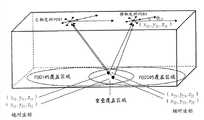
1.空间。根据本发明实施方式的空间是指目标在其中移动的空间。例如房间、办公室、会议室等等。图1示出了以房间为例子的一个基准空间10的示意图。应当理解,本发明实施方式并不局限于图1所示的四边形的房间,而可以是任何的形状。通常为了知道目标在空间中的位置,必须知道空间的尺寸。根据本发明的一个实施方式,提供了一种用于确定空间的尺寸的技术方案,这将在下文中进行详细描述。1. Space. A space according to an embodiment of the present invention refers to a space in which an object moves. Such as rooms, offices, meeting rooms, etc. FIG. 1 shows a schematic diagram of a reference space 10 taking a room as an example. It should be understood that the embodiments of the present invention are not limited to the quadrilateral room shown in FIG. 1 , but may be in any shape. Usually in order to know the position of the object in space, the dimensions of the space must be known. According to an embodiment of the present invention, a technical solution for determining the size of a space is provided, which will be described in detail below.
2.空间特征点。空间特征点是用于确定空间的位置点。例如,在如图1所示的以房间为例子的空间10中,空间特征点可以是房间角落位置点11、12和13。原则上,可以选择该空间内的任何点作为空间特征点,只要能确定该空间即可。应当理解,当房间是其他多边形,例如六边形时,可以采用多边形的顶点为特征点。如果房间为其他不规则形状时,则可以使用房间周边上的至少三个点来拟合出一个多边形,从而可以像对待多边形房间一样对待其他形状的房间。2. Spatial feature points. A spatial feature point is a position point for determining a space. For example, in a room 10 as shown in FIG. 1 as an example, the spatial feature points may be room corner position points 11 , 12 and 13 . In principle, any point in this space can be selected as a spatial feature point, as long as the space can be determined. It should be understood that when the room is another polygon, such as a hexagon, the vertices of the polygon may be used as feature points. If the room has other irregular shapes, at least three points on the perimeter of the room can be used to fit a polygon, so that other shaped rooms can be treated like polygonal rooms.
3.定位设备(POD:Positioning on One Device)。根据本发明实施方式的定位设备是用于确定空间中的位置点的坐标的设备。图2所示为本发明的实施方式采用的定位设备的一个例子。如图2所示,本发明的实施方式所采用的定位设备是一种具有多个叶节点的传感器阵列。叶点节点的数量至少是两个,也就是说定位设备包括至少两个叶节点传感器和一个处于中间的传感器。通常叶节点越多,则定位精度也越高。在图2中示出的定位设备具有6个叶节点。在具体应用中,如图1所示,定位设备14通常被布置在空间10的顶部,其能够发射测距信号到空间10中的目标位置点,或者接收来自空间10中的目标位置点的测距信号。3. Positioning device (POD: Positioning on One Device). A positioning device according to an embodiment of the present invention is a device for determining coordinates of a position point in space. FIG. 2 shows an example of a positioning device used in an embodiment of the present invention. As shown in FIG. 2 , the positioning device used in the embodiment of the present invention is a sensor array with multiple leaf nodes. The number of leaf nodes is at least two, that is to say, the positioning device includes at least two leaf node sensors and one intermediate sensor. Generally, the more leaf nodes, the higher the positioning accuracy. The positioning device shown in FIG. 2 has 6 leaf nodes. In a specific application, as shown in FIG. 1 , the positioning device 14 is usually arranged on the top of the space 10, and it can transmit a distance measurement signal to a target position point in the space 10, or receive a distance measurement signal from a target position point in the space 10. distance signal.
在本发明的实施方式中,仅使用定位设备的接收功能。定位设备本身可以具有计算功能,用于根据接收到的测距信号进行相关计算。或者,定位设备可以通过有线或无线方式连接到远程的服务器或专用计算设备,从而在远程服务器或者专用计算设备处执行基于测距信号的相关计算。通常可以基于定位设备从目标位置点接收的测距信号,利用传统的三角定位或者坐标变换方法来得到目标位置点在空间的坐标。定位设备本身的结构和功能是本领域已知的,在此不作赘述。In an embodiment of the invention, only the receiving function of the positioning device is used. The positioning device itself may have a calculation function for performing correlation calculations based on received ranging signals. Alternatively, the positioning device may be connected to a remote server or a dedicated computing device in a wired or wireless manner, so that the remote server or the dedicated computing device performs correlation calculation based on the ranging signal. Generally, based on the ranging signal received by the positioning device from the target position point, traditional triangulation or coordinate transformation methods can be used to obtain the coordinates of the target position point in space. The structure and functions of the positioning device itself are known in the art, and will not be repeated here.
4.绝对坐标系。在本发明的实施方式中,将以空间中的一个位置点为坐标原点的坐标系称为绝对坐标系。可以将空间的任何一个特征点作为绝对坐标系统的原点。例如,在图1所示的空间10中,以特征点11作为绝对坐标系的原点。当然,本领域技术人员可以理解的是,选择其中一个特征点作为原点只是方便计算,而不是必须的。如果将其他位置点作为坐标原点,则通过简单的平移就可以得到以上描述的绝对坐标系。这对于本领域技术人员而言是很熟悉的,因此这里将不再详述。4. Absolute coordinate system. In the embodiments of the present invention, a coordinate system with a point in space as the coordinate origin is referred to as an absolute coordinate system. Any feature point in space can be used as the origin of the absolute coordinate system. For example, in the space 10 shown in FIG. 1 , the feature point 11 is used as the origin of the absolute coordinate system. Of course, those skilled in the art can understand that selecting one of the feature points as the origin is just for convenience of calculation, but not necessary. If other position points are taken as the coordinate origin, the absolute coordinate system described above can be obtained by simple translation. This is familiar to those skilled in the art, so it will not be described in detail here.
5.相对坐标系。在本发明的实施方式,将以定位设备自身为原点的坐标系称为相对坐标系。该相对坐标的原点即为该定位设备的中心点,X轴方向为该定位设备的第一个传感器(未示出)。这里所称的“第一个传感器”可以在对定位设备进行制造初始配置的时候进行规定。当X轴被规定时,与该X轴处垂直并处于该定位设备平面内的方向并定义为Y轴。5. Relative coordinate system. In the embodiments of the present invention, the coordinate system with the positioning device itself as the origin is referred to as a relative coordinate system. The origin of the relative coordinates is the center point of the positioning device, and the X-axis direction is the first sensor (not shown) of the positioning device. The "first sensor" referred to here may be specified during initial manufacturing configuration of the positioning device. When the X axis is specified, the direction perpendicular to the X axis and within the plane of the positioning device is defined as the Y axis.
当对定位设备进行标定时,则相对坐标系与绝对坐标系之间可能存在一定的夹角θ,在本发明中将该夹角称为定位设备的在绝对坐标系中的设置角度,如图1所示的POD角度18。这样,定位设备在空间的位置(如图1所示的POD位置17)的位置参数包括定位设备在绝对坐标系下的绝对坐标以及设置角度θ。根据本发明的一个实施方式,提供一种对空间中的定位设备进行标定(即确定定位设备的位置参数)的技术方案,这将在下文中进行详细描述。When the positioning device is calibrated, there may be a certain angle θ between the relative coordinate system and the absolute coordinate system. In the present invention, this angle is called the setting angle of the positioning device in the absolute coordinate system, as shown in the figure 1 shows the pod angle 18. In this way, the position parameters of the position of the positioning device in space (POD position 17 shown in FIG. 1 ) include the absolute coordinates of the positioning device in the absolute coordinate system and the setting angle θ. According to an embodiment of the present invention, a technical solution for calibrating a positioning device in space (that is, determining a position parameter of the positioning device) is provided, which will be described in detail below.
6.标签。在本发明实施方式中的标签是指能够发射测距信号的标签,例如射频标签。在本发明的实施方式,可以将标签放置在空间中的位置点处,以便通过定位设备接收标签发出的测距信号来得到位置点的相对坐标或者绝对坐标。测距信号的形式可以是多种,可以包括但不限于超声波、红外线、激光、射频信号、超宽带脉冲信号、多普勒信号以及声波等等。另外,通过定位设备和标签来确定位置点的相对坐标或者绝对坐标是本领域已知的,在此不作赘述。6. Labels. The tags in the embodiments of the present invention refer to tags capable of transmitting ranging signals, such as radio frequency tags. In the embodiment of the present invention, the tag can be placed at the location point in space, so that the relative or absolute coordinates of the location point can be obtained by receiving the ranging signal sent by the tag by the positioning device. The ranging signal can be in various forms, including but not limited to ultrasonic waves, infrared rays, lasers, radio frequency signals, ultra-wideband pulse signals, Doppler signals, and sound waves. In addition, it is known in the art to determine the relative coordinates or absolute coordinates of a location point by using a positioning device and a tag, and details are not described here.
7.关注区域(AOI,Area of Interest)和关注区域特征点。关注区域是指用户出于特定的应用需求(例如安全目的)而表征了的地理区域。关注区域位于空间中。例如,在“安全桌面”的应用中,该桌面被定义为关注区域。只有在此关注区域之内才允许对机密信息的访问,而一旦超出该关注区域或处于该关注区域之外,则禁止对该机密信息的任何访问。关注区域特征点是可以用来表征关注区域的那些位置点。图1示出了关注区域15和关注区域特征点16。根据本发明的一个实施方式,提供一种表征在空间中的关注区域的技术方案,这将在下文中作详细描述。7. Area of Interest (AOI, Area of Interest) and feature points of the area of interest. An area of interest refers to a geographic area characterized by a user for specific application requirements (eg, security purposes). The region of interest is located in space. For example, in the application of "secure desktop", the desktop is defined as the area of interest. Access to confidential information is permitted only within this area of concern, and any access to the confidential information is prohibited once outside or outside of this area of concern. Region of interest feature points are those position points that can be used to characterize the region of interest. FIG. 1 shows a region of interest 15 and region of interest feature points 16 . According to an embodiment of the present invention, a technical solution for characterizing a region of interest in space is provided, which will be described in detail below.
下面结合附图对本发明的各个实施方式进行描述。应该理解,这些实施方式只是用于说明目的,而并非限定性的。Various embodiments of the present invention will be described below in conjunction with the accompanying drawings. It should be understood that these embodiments are for illustrative purposes only, not limiting.
首先描述根据本发明一个实施方式用于对定位设备进行标定的技术方案。图3示出了根据本发明的一个实施方式的系统100的示意图,该系统100用于测量空间的尺寸并在空间中对定位设备进行标定。Firstly, a technical solution for calibrating a positioning device according to an embodiment of the present invention is described. Fig. 3 shows a schematic diagram of a system 100 according to an embodiment of the present invention, the system 100 is used for measuring the size of a space and calibrating a positioning device in the space.
如图1所示,该系统100可以包括:能够发射测距信号的标签110,其放置在空间中作为空间特征点的一个或者多个位置点处;位于空间中的定位设备120,其中定位设备120被配置为根据来自标签110的测距信号获取上述空间特征点相对于定位设备自身的相对坐标;以及服务器130,被配置为根据获取的相对坐标来确定定位设备120在空间中的位置参数,从而标定定位设备120。As shown in FIG. 1 , the system 100 may include: a
下面详细描述系统100的实现。具体地,根据本发明的一个实施方式,首先选择空间中的三个空间特征点(在图1中显示为基准空间特征点)并将能够发射测距信号的标签110放置在这些特征点上,以便确定三个空间特征点相对于定位设备自身的相对坐标。在本发明的的一个实施方式中,可选地,可以通过在每个空间特征点分别放置一个标签来确定空间特征点的相对坐标。另外,可选地,也可以将一个标签先后放在选择的空间特征点处来确定空间特征点的相对坐标。标签110本身是本领域已知的,在此不作赘述。The implementation of system 100 is described in detail below. Specifically, according to an embodiment of the present invention, first select three spatial feature points in space (shown as reference spatial feature points in FIG. 1 ) and
接下来,可以在该空间中设置定位设备120。定位设备120可以设置在空间的任何地方。可选地,定位设备120设置在空间的顶部,而且初始设置的时候是任意的,即可以设置在顶部的任何位置。然后,定位设备120可以根据来自标签110的测距信号获取上述空间特征点相对于定位设备自身的相对坐标。Next, a
例如,在本发明的一个实施方式中,定位设备120以自身的中心为坐标原点,确定出定位设备120的三个传感器相对于定位设备自身的相对坐标。然后,三个传感器可以根据来自空间特征点处的标签110的测距信号得到从上述空间特征点到各个传感器的距离。最后再利用从上述空间特征点到各个传感器的距离以及各个传感器的相对坐标,根据传统的三角定位算法(例如最小均方差算法),来得到各个空间特征点相对于定位设备120自身的相对坐标。应当理解,通过传统三角定位算法得到各个空间特征点相对于定位设备120自身的相对坐标是本领域已知的,在此不作赘述。For example, in one embodiment of the present invention, the
然后,根据本发明的实施方式,服务器130通过相应的计算,可以自动地计算出定位设备120在空间内的位置参数,从而完成对定位设备120的自动标定,这将在后面详细描述。可选地,该位置参数可以包括定位设备120在空间中的绝对坐标(x,y,z)以及定位设备120在空间中的设置角度θ。这将在后文中进行描述。Then, according to the embodiment of the present invention, the
应当理解,设置标签110和定位设备120之间并不存在先后关系。可以同时设置二者,也可以先设置定位设备120,然后再在空间的空间特征点处放置标签110。It should be understood that there is no sequence relationship between the setting
下面结合图4和图5来以四边形的房间为例来描述服务器如何根据所获取的三个基准空间特征点的相对坐标来定位设备120在空间内的位置参数。The following uses a quadrilateral room as an example to describe how the server locates the position parameters of the
首先,计算该房间(也就是基准空间)的尺寸。First, calculate the dimensions of the room (that is, the base space).
如图4所示,设获取的地面上的三个基准空间特征点的相对坐标分别为(x1,y1,z1),(x2,y2,z2)以及(x3,y3,z3),其中,这些相对坐标已经利用定位设备120和标签110获知。特征点(x1,y1,z1)被定义为基准空间绝对坐标系的原点(0,0,0)。该房间的长度(1)、宽度(w)、高度(h)、定位设备120的绝对坐标(x,y,z)以及POD的设置角度θ为未知数。As shown in Figure 4, suppose the relative coordinates of the three reference space feature points on the ground are (x1 , y1 , z1 ), (x2 , y2 , z2 ) and (x3 , y3 , z3 ), where these relative coordinates have been known by the
首先确定定位设备120的z坐标,即定位设备的高度(h)。通常,由于屋顶和地面是平行的,所以定位设备120的高度为h,也就是说z=h=z1=z2=z3。但是,考虑到可能存在的误差,例如由于地面不平整所引起的误差,则z坐标的计算为z=h=(z1+z2+z3)/3。First determine the z-coordinate of the
当计算得到z之后,剩下的问题就是在二维空间中对其余未知数进行求解。After calculating z, the remaining problem is to solve the remaining unknowns in the two-dimensional space.
图5示出了根据本发明的一个实施方式在二维空间中计算上述未知数(例如房间的长度(l)、宽度(w)、POD的绝对坐标(x,y)以及POD的角度θ)的示意图。Fig. 5 shows the process of calculating the above-mentioned unknowns (such as the length (l), width (w) of the room, the absolute coordinates (x, y) of the POD and the angle θ of the POD) in a two-dimensional space according to an embodiment of the present invention. schematic diagram.
如图5所示,实线所表示的坐标系为本发明中的绝对坐标系,而虚线所表示的坐标系为本发明中以定位设备为原点的相对坐标系。两个坐标系的夹角,即定位设备的设置角度为θ。As shown in FIG. 5 , the coordinate system represented by the solid line is the absolute coordinate system in the present invention, and the coordinate system represented by the dotted line is the relative coordinate system in the present invention with the positioning device as the origin. The angle between the two coordinate systems, that is, the setting angle of the positioning device is θ.
根据图5,利用常规的坐标变换,可以得出如下方程组(1):According to Fig. 5, using conventional coordinate transformation, the following equations (1) can be obtained:
x1cos(θ)-y1sin(θ)+x=0x1 cos(θ)-y1 sin(θ)+x=0
x1sin(θ)+y1cos(θ)+y=0x1 sin(θ)+y1 cos(θ)+y=0
x2cos(θ)-y2sin(θ)+x=lx2 cos(θ)-y2 sin(θ)+x=l
x2sin(θ)+y2cos(θ)+y=w (1)x2 sin(θ)+y2 cos(θ)+y=w (1)
x3cos(θ)-y3sin(θ)+x=lx3 cos(θ)-y3 sin(θ)+x=l
x3sin(θ)-y3cos(θ)+y=0x3 sin(θ)-y3 cos(θ)+y=0
(x1-x3)2+(y1-y3)2=l2(x1 -x3 )2 +(y1 -y3 )2 =l2
(x2-x3)2+(y2-y3)2=w2(x2 -x3 )2 +(y2 -y3 )2 =w2
本领域技术人员可以理解的是,如果采用更多的基准空间特征点,将增加方程组(1)的方程数量,也就是增加系数矩阵的行数。这对于本领域技术人员而言是很熟悉的,这里将不再描述。Those skilled in the art can understand that if more reference space feature points are used, the number of equations in the equation group (1) will be increased, that is, the number of rows of the coefficient matrix will be increased. This is familiar to those skilled in the art and will not be described here.
对该方程组(1)求解,可以得出定位设备的绝对坐标(x,y)和角度θ以及该基准空间的长度l和宽w,计算过程如下:Solving the equations (1), the absolute coordinates (x, y) and angle θ of the positioning device and the length l and width w of the reference space can be obtained. The calculation process is as follows:
这样就可以得到基准空间的尺寸以及定位设备在该基准空间中的位置参数,例如定位设备的绝对坐标(x,y,z)和设置角度θ,从而自动完全空间尺寸的确定和定位设备的标定。In this way, the size of the reference space and the position parameters of the positioning device in the reference space can be obtained, such as the absolute coordinates (x, y, z) of the positioning device and the setting angle θ, so as to automatically determine the complete space size and the calibration of the positioning device .
应当理解,一旦该定位设备120被标定,其可以利用现有三角定位算法直接得到空间中任何一点在该空间中的绝对坐标。另外,定位设备120也可以通过相对坐标与绝对坐标之间的转换来得到空间中的任意一点的绝对坐标。即首先得到空间中的位置点相对于定位设备自身的相对坐标,再通过常规的坐标转换来得到位置点的绝对坐标。It should be understood that once the
在上面的例子,通过选择三个空间特征点来描述了根据本发明实施方式的用于对定位设备进行标定的过程。然而,并发明并不局限于三个空间特征点的实现。在特定实现中,也可以只使用一个或者两个空间特征点来对定位设备进行标定。例如,当在房间顶部放置定位设备时,可以使得其自身相对坐标系的X轴(例如第一个传感器的方向)与空间绝对坐标系的X轴平行。在这种情况下,定位设备的设置角度θ实际上为零。此时,以房屋一个角落为绝对坐标系的原点,即房屋的该角落的绝对坐标为(0,0,0)。可以通过定位设备获得该角落相对于定位设备的相对坐标。通常,如上所示,定位设备的Z轴坐标等于该角度相对于定位设备相对坐标的Z轴坐标值。然后,在二维平面内,根据该角落的相对坐标和绝对坐标,通过普通的坐标系平移变换,即可得到该定位设备的绝对坐标的X轴和Y轴坐标。具体变换是本领域已知的,在此不作赘述。In the above example, the process of calibrating the positioning device according to the embodiment of the present invention is described by selecting three spatial feature points. However, the invention is not limited to the realization of three spatial feature points. In a specific implementation, only one or two spatial feature points may be used to calibrate the positioning device. For example, when a positioning device is placed on the top of a room, the X-axis of its own relative coordinate system (for example, the direction of the first sensor) may be parallel to the X-axis of the space absolute coordinate system. In this case, the setting angle θ of the positioning device is practically zero. At this time, a corner of the house is taken as the origin of the absolute coordinate system, that is, the absolute coordinates of the corner of the house are (0, 0, 0). The relative coordinates of the corner relative to the positioning device can be obtained through the positioning device. Typically, as indicated above, the Z-coordinate of the positioning device is equal to the Z-coordinate value of the angle relative to the relative coordinates of the positioning device. Then, in the two-dimensional plane, according to the relative coordinates and absolute coordinates of the corner, the X-axis and Y-axis coordinates of the absolute coordinates of the positioning device can be obtained through ordinary coordinate system translation transformation. The specific transformation is known in the art, and will not be repeated here.
应当理解,根据本发明的实施方式,选择的空间特征点越多,根据坐标变换得到的方程的数目越多,由此所确定的定位设备的位置参数越精确。It should be understood that, according to the embodiment of the present invention, the more spatial feature points are selected, the more equations are obtained according to the coordinate transformation, and thus the more accurate the determined position parameters of the positioning device are.
上述实施方式描述了在四边形的房间中对定位设备进行标定的过程。但是,应当理解,本发明并不局限四边形房间的空间。如果空间为其他不规则形状时,则可以使用空间周边上的三个点来拟合出一个多边形,从而可以像对待多边形空间一样对待其他形状的空间。The above embodiments describe the process of calibrating the positioning device in a quadrilateral room. However, it should be understood that the present invention is not limited to the space of quadrilateral rooms. If the space is other irregular shapes, you can use three points on the periphery of the space to fit a polygon, so that you can treat other shapes of space like polygonal spaces.
根据本发明的另一个实施方式,如图6所示,也提供一种用于对布置在空间中的定位设备进行标定的设备200,其中,该空间中的一个或者多个位置点被选择作为空间特征点。该设备200可以包括:接收装置210,用于接收空间特征点相对于定位设备自身的相对坐标;以及确定装置220,用于根据相对坐标来确定定位设备在空间中的位置参数从而标定所述定位设备。确定装置220的工作过程与上述结合图3所描述的实施方式中根据相对坐标来确定定位设备在空间中的位置参数的方式相同。According to another embodiment of the present invention, as shown in FIG. 6 , a device 200 for calibrating a positioning device arranged in a space is also provided, wherein one or more position points in the space are selected as Spatial feature points. The device 200 may include: receiving means 210, used to receive the relative coordinates of spatial feature points relative to the positioning device itself; equipment. The working process of the determining device 220 is the same as the method of determining the position parameter of the positioning device in space according to the relative coordinates in the embodiment described above in conjunction with FIG. 3 .
根据本发明的该实施方式,空间特征点处可以放置有能够发射测距信号的标签。相对坐标可以是定位设备根据来自标签的测距信号来获取的,这与上述图3的定位设备120的操作过程相同。According to this embodiment of the present invention, tags capable of transmitting ranging signals may be placed at spatial feature points. The relative coordinates can be obtained by the positioning device according to the ranging signal from the tag, which is the same as the operation process of the
应当理解,在具体实现时,设备200可以集成在图3所示的定位设备120中,也可以集成在图3所示的与该定位设备120连接的服务器130中。It should be understood that, during specific implementation, the device 200 may be integrated in the
下面描述根据本发明另一实施方式的对定位设备进行标定的技术方案。通常在比较大的房间中,可以设置多个定位设备,以对整个房间进行覆盖。因此,如图7所示,根据本发明的另一实施方式,提供一种系统300,用于标定多个定位设备。该系统300可以包括:能够发射测距信号的标签310,放置于空间中的一个或者多个位置点处;已标定的第一定位设备320,被配置为根据来自标签310的测距信号获取位置点在空间中的绝对坐标;第二定位设备330,被配置为根据来自标签310的测距信号获取位置点相对于第二定位设备330的相对坐标;以及服务器340,被配置为根据绝对坐标和相对坐标来确定第二定位设备330在空间中的位置参数,从而标定第二定位设备330,其中位置点处于第一定位设备320和第二定位设备330的重叠覆盖区域中。The following describes a technical solution for calibrating a positioning device according to another embodiment of the present invention. Usually in a relatively large room, multiple positioning devices can be set up to cover the entire room. Therefore, as shown in FIG. 7 , according to another embodiment of the present invention, a system 300 is provided for calibrating multiple positioning devices. The system 300 may include: a
下面结合图8来描述系统300的具体实现。为方便描述,在图8中,将已经在空间中标定好的第一定位设备320表示为POD1,而将待标定的第二定位设备330表示为POD2。The specific implementation of the system 300 is described below with reference to FIG. 8 . For convenience of description, in FIG. 8 , the
在图8中,POD1已经进行了标定。需要指出的是,对POD1的标定可以是通过如上结合图3-6所描述的技术方案来标定的,也可以是任何其它合适的方法来标定。In Figure 8, POD1 has been calibrated. It should be noted that the calibration of POD1 may be performed through the technical solution described above in conjunction with FIGS. 3-6 , or any other suitable method.
为了标定POD2,需要首先确定POD1和POD2的覆盖区域,并确保这两个POD具有重叠的覆盖区域。如图8所示,POD1的覆盖区域被称为第一覆盖区域,而POD2具有第二覆盖区域,二者具有重叠覆盖区域。确定重叠覆盖区域有多种方法,例如,可以通过检测POD1和POD2能否同时检测到特定位置处的标签来确定该位置是否处于重叠覆盖区域中。也可以其他方法来确定重叠覆盖区域。In order to calibrate POD2, it is necessary to first determine the coverage areas of POD1 and POD2, and ensure that the two PODs have overlapping coverage areas. As shown in FIG. 8 , the coverage area of POD1 is referred to as a first coverage area, while POD2 has a second coverage area, both of which have overlapping coverage areas. There are many methods for determining the overlapping coverage area. For example, whether the location is in the overlapping coverage area can be determined by detecting whether POD1 and POD2 can detect tags at a specific location at the same time. Other methods may also be used to determine overlapping coverage areas.
为了标定POD2,需要计算出该POD2在该房间中的绝对坐标(x20,y20,z20)以及该POD2的角度θ20。具体地,在重叠覆盖区域中选择两个位置点(为方便描述,称为重叠覆盖区域位置点),并分别在所述两个位置点放置标签(为方便描述,称为重叠覆盖区域标签),以发射测距信号(为方便描述,称为重叠覆盖区域测距信号)。可选地,使用一个标签先后放在至少两个位置点,来发射测距信号。In order to calibrate POD2, the absolute coordinates (x20 , y20 , z20 ) of the POD2 in the room and the angle θ20 of the POD2 need to be calculated. Specifically, two location points are selected in the overlapping coverage area (for convenience of description, called overlapping coverage area location points), and labels are respectively placed on the two location points (for convenience of description, called overlapping coverage area labels) , to transmit a ranging signal (for convenience of description, it is called overlapping coverage area ranging signal). Optionally, a tag is used to place at least two location points successively to transmit a ranging signal.
根据一个实施例,POD1可以首先通过来自标签的测距信号得到这两个重叠覆盖区域位置点相对于自身的相对坐标,然后再通过坐标变换得到这两个重叠覆盖区域位置点的绝对坐标,例如为(x11,y11,z11)和(x12,y12,z12)。可替换地,POD1可以直接根据来自标签的测距信号通过现有的三角定位算法直接得到这两个重叠覆盖区域位置点的绝对坐标(x11,y11,z11)和(x12,y12,z12)。According to an embodiment, POD1 can first obtain the relative coordinates of the location points of the two overlapping coverage areas relative to itself through the ranging signal from the tag, and then obtain the absolute coordinates of the location points of the two overlapping coverage areas through coordinate transformation, for example are (x11 , y11 , z11 ) and (x12 , y12 , z12 ). Alternatively, POD1 can directly obtain the absolute coordinates (x11 , y11 , z11 ) and (x12 , y12 , z12 ).
同时,POD2可以在其自己的坐标系中得到这两个重叠覆盖区域位置点的相对坐标,例如为(x21,y21,z21)和(x22,y22,z22)。可以看出,由于POD1已经经过标定,所以这两个重叠覆盖区域位置点的绝对坐标是已知的。此外,由于该POD2也设置在例如屋顶,所以该POD2的z20=h=(z1+z2+z3)/3。由此,对POD2的坐标(x20,y20,z20)以及角度θ20的计算被简化到二维坐标中。At the same time, POD2 can obtain the relative coordinates of the two overlapping coverage area points in its own coordinate system, such as (x21 , y21 , z21 ) and (x22 , y22 , z22 ). It can be seen that since POD1 has been calibrated, the absolute coordinates of the location points of the two overlapping coverage areas are known. In addition, since this POD2 is also installed on the roof, for example, z20 =h=(z1 +z2 +z3 )/3 of this POD2. Thus, the calculation of the coordinates (x20 , y20 , z20 ) of POD2 and the angle θ20 is simplified into two-dimensional coordinates.
通过几何学分析,可以通过以下方程组来计算POD2在该基准空间中的绝对坐标:Through geometric analysis, the absolute coordinates of POD2 in this reference space can be calculated by the following equations:
通过方程组(7)可以推导出如下矩阵计算:The following matrix calculation can be deduced through equation group (7):
对该矩阵求解,则可以得出第二定位设备的坐标以及角度θ20:By solving this matrix, the coordinates of the second positioning device and the angle θ20 can be obtained:
其中,in,
由此可以计算出待标定的POD2的绝对坐标及其角度。From this, the absolute coordinates and angles of the POD2 to be calibrated can be calculated.
应当理解,在上面的例子,通过选择两个重叠区域位置点来描述了根据本发明实施方式的用于对定位设备进行标定的过程。然而,并发明并不局限于两个重叠覆盖区域位置点。在特定实现中,也可以只使用一个重叠覆盖区域位置点来对定位设备进行标定。例如,当第一个定位设备已经标定好而对第二个定位设备进行标定时,可以设置使得第二个定位设备的X轴与第一个定位设备的X轴平行。在这种情况下,第二定位设备的设置角度与第一个定位设备的设备角度相同,为已知量。此时,利用已标定的第一定位设备获得一个重叠覆盖区域位置点的绝对坐标,以及通过第二定位设备获得该位置点相对于第二定位设备的相对坐标。然后,通过普通的坐标变换,即可得到该第二定位设备的绝对坐标。It should be understood that in the above example, the process for calibrating the positioning device according to the embodiment of the present invention is described by selecting two overlapping area position points. However, the invention is not limited to two overlapping coverage area locations. In a specific implementation, only one overlapping coverage area location point may be used to calibrate the positioning device. For example, when the first positioning device has been calibrated and the second positioning device is calibrated, it can be set so that the X axis of the second positioning device is parallel to the X axis of the first positioning device. In this case, the setting angle of the second positioning device is the same as that of the first positioning device, which is a known quantity. At this time, the absolute coordinates of a position point in the overlapping coverage area are obtained by using the first positioning device that has been calibrated, and the relative coordinates of the position point relative to the second positioning device are obtained by the second positioning device. Then, through ordinary coordinate transformation, the absolute coordinates of the second positioning device can be obtained.
需要指出的是,所选择的重叠覆盖区域位置点也可以多于两个,这将增加以上系数矩阵的行数,而计算过程与以上计算过程相同。应该理解,选择更多重叠覆盖区域位置点有利于提高定位精度。It should be pointed out that the selected overlapping coverage area location points can also be more than two, which will increase the number of rows of the above coefficient matrix, and the calculation process is the same as the above calculation process. It should be understood that selecting more overlapping coverage area location points is beneficial to improve positioning accuracy.
更进一步而言,可以采用以上方法并根据已标定的POD来逐步地标定更多的POD,从而覆盖更大的区域。这里将不再详述。Furthermore, more PODs can be gradually calibrated according to the calibrated PODs by adopting the above method, so as to cover a larger area. It will not be described in detail here.
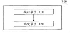
根据本发明的一个实施方式,如图9所示,也提供一种用于对定位设备(例如POD2)进行标定的设备400。该设备400可以包括:接收装置410,用于接收一个或者多个位置点在所述空间中的绝对坐标以及所述位置点相对于所述定位设备的相对坐标;以及确定装置420,用于根据所述绝对坐标和所述相对坐标来确定所述定位设备在所述空间中的位置参数,从而标定所述定位设备。确定装置420的工作工程与上述参考图7和8的实施方式根据绝对坐标和相对坐标来确定定位设备在空间中的位置参数的方式相同。According to an embodiment of the present invention, as shown in FIG. 9 , a
可以理解的是,该位置点在所述空间中的绝对坐标可以通过任何已知的方式来获得。可选地,根据本发明的实施方式,所述至少两个位置点的绝对坐标是通过已经标定好的另一定位设备(例如POD1)来确定的。其中至少两个位置点位于定位设备和已标定的另一定位设备的重叠覆盖区域中,在至少两个位置点处放置有能够发射测距信号的标签,所述定位设备能够根据来自标签的测距信号获取所述相对坐标,以及所述另一定位设备能够根据来自标签的测距信号获取所述绝对坐标。当然,位置点在所述空间中的绝对坐标也可以通过人工的方式来确定。It can be understood that the absolute coordinates of the location point in the space can be obtained by any known means. Optionally, according to an embodiment of the present invention, the absolute coordinates of the at least two position points are determined by another calibrated positioning device (such as POD1). Wherein at least two position points are located in the overlapping coverage area of the positioning device and another positioning device that has been calibrated, tags capable of transmitting ranging signals are placed at at least two position points, and the positioning device can The relative coordinates are obtained from a ranging signal, and the other positioning device is capable of obtaining the absolute coordinates based on a ranging signal from a tag. Of course, the absolute coordinates of the location point in the space may also be manually determined.
再次需要指出的是,设备400可以集成在图7所示的第一定位设备320或者第二定位设备330(例如POD2)中,也可以集成在服务器340中。It should be pointed out again that the
从上文中描述了根据本发明的实施方式对定位设备进行标定的方法,可以看出,在对定位设备进行标定的时候,无须手动测量房间的长、宽以及定位设备的设置角度。并且,由于采用了标签,可以避免进行人工测量,从而提高了工作效率,改进了标定精度。From the above description of the method for calibrating the positioning device according to the embodiment of the present invention, it can be seen that when calibrating the positioning device, it is not necessary to manually measure the length and width of the room and the installation angle of the positioning device. Moreover, due to the use of labels, manual measurement can be avoided, thereby improving work efficiency and improving calibration accuracy.
下面描述根据本发明的一个实施方式的在确定了基准空间并标定了定位设备之后表征关注区域的技术方案。回到图1,其中示出了关注区域。关注区域可以处于空间的任何地方,也可以选择任何形状的区域作为关注区域。当佩戴标签的人员进入该关注区域内时,则根据需要来确定该人员与空间的关系,例如允许/禁止该人员访问特定的机密信息等等。显然,为了达到该目的,需要确定该关注区域的边界,即表征该关注区域。The technical solution for characterizing the region of interest after the reference space is determined and the positioning device is calibrated according to an embodiment of the present invention is described below. Returning to Figure 1 , the region of interest is shown. The ROI can be anywhere in the space, and any shape can be selected as the ROI. When a person wearing a tag enters the attention area, the relationship between the person and the space is determined as required, such as allowing/prohibiting the person from accessing specific confidential information and the like. Obviously, in order to achieve this goal, it is necessary to determine the boundary of the ROI, that is, to characterize the ROI.
需要指出的是,关注区域所处的空间并非必须是根据本发明图3-图6的实施方式所确定的基准空间,而可以是根据任何现有技术包括无标签的手动测量等方式所确定的空间。而且确定关注区域的定位设备也并不必须是图2所示的定位设备,而可以是任何已知的定位设备或定位设备阵列。It should be pointed out that the space where the region of interest is located is not necessarily the reference space determined according to the embodiments of Fig. 3-Fig. space. Moreover, the positioning device for determining the region of interest is not necessarily the positioning device shown in FIG. 2 , but may be any known positioning device or array of positioning devices.
如图10所示,根据本发明一个实施方式,提供一种系统500,用于确定或表征关注区域,该系统500可以包括:能够发射测距信号的标签510,放置在能够表征空间中的关注区域的关注区域特征点处;空间中的定位设备520,被配置为根据来自标签510的测距信号获取关注区域特征点的位置参数;以及服务器530,被配置为根据所述关注区域特征点的位置参数来表征所述关注区域。As shown in FIG. 10 , according to one embodiment of the present invention, a system 500 is provided for determining or characterizing an area of interest. The system 500 may include: a
可以理解的是,当该关注区域处于所确定的空间中时,其可以采用与基准空间相同的基准坐标。也就是说该关注区域中的任何一点的绝对坐标均以该基准空间的某个点(例如房间角落)为原点为基准。It can be understood that, when the attention region is in the determined space, it may adopt the same reference coordinates as the reference space. That is to say, the absolute coordinates of any point in the attention area are based on a certain point (such as a room corner) in the reference space as the origin.
对于关注区域的形状而言,可以划分为两类,即规则形状和不规则形状,下面分别描述根据本发明的针对规则形状和不规则形状的确定关注区域的技术方案。这里需要说明的是,由于优选的是该关注区域与水平面平行,因此该关注区域的高度可以是所选择的任一关注区域特征点的高度。但为了防止出现的定位误差,选择这些关注区域特征点高度的平均值,在选择了关注区域的高度之后,剩下的问题就是在二维坐标中确定该关注区域的形状。这与确定基准空间时采用的对若干特征点的z坐标求平均是相同的。因此此处省略对其z坐标的描述,而只描述在二维坐标中确定该关注区域的方法。The shape of the ROI can be divided into two types, namely regular shape and irregular shape. The following describes the technical solutions for determining the ROI according to the present invention for the regular shape and the irregular shape respectively. It should be noted here that since it is preferable that the attention area is parallel to the horizontal plane, the height of the attention area may be the height of any selected feature point of the attention area. However, in order to prevent positioning errors, the average height of the feature points of these regions of interest is selected. After selecting the height of the region of interest, the remaining problem is to determine the shape of the region of interest in two-dimensional coordinates. This is the same as calculating the average of the z coordinates of several feature points when determining the reference space. Therefore, the description of the z coordinate is omitted here, and only the method for determining the attention region in two-dimensional coordinates is described.
现在参考图11到16详细描述图10所示系统500的具体实现。图11示出了根据本发明一个实施方式的表征多边形关注区域的方法的示意图。A specific implementation of the system 500 shown in FIG. 10 will now be described in detail with reference to FIGS. 11 to 16 . Fig. 11 shows a schematic diagram of a method for characterizing a polygonal ROI according to an embodiment of the present invention.
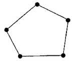
如图11所示,该多边形例如具有5个边,则该关注区域特征点优选为该多边形的5个顶点。在该多边形的顶点处分别放置如图10所示的标签510,该标签可以向定位设备520发送测距信号。然后,定位设备520可以接收该测距信号,并从该测距信号中获取这5个关注区域特征点在空间中的坐标。可选地,可以首先获取这5个关注区域特征点相对于该定位设备520自身的相对坐标。然后利用传统的坐标变换,根据该相对坐标以及定位设备520在空间中的位置参数得到这些关注区域特征点在基准空间中的绝对坐标。这样,可以根据该绝对坐标来对该多边形,例如5边形的AOI区域进行表征。具体而言,就是将这些顶点连接起来以确定该多边形关注区域。As shown in FIG. 11 , the polygon has, for example, 5 sides, and the feature points of the region of interest are preferably 5 vertices of the polygon.
应当理解,也可以利用关注区域特征点相对于定位设备的相对坐标来表征关注区域。It should be understood that the relative coordinates of the feature points of the region of interest relative to the positioning device may also be used to characterize the region of interest.
图12示出了根据本发明另一个实施方式的表征圆形关注区域的方法的示意图。Fig. 12 shows a schematic diagram of a method for characterizing a circular region of interest according to another embodiment of the present invention.
如图12所示,该关注区域为圆形,则该关注区域的特征点优选为该圆形的圆心和圆边上的任意点。设计算得到的该圆心的二维绝对坐标为(x1,,y1),圆边上的任意一点的二维绝对坐标为(x2,y2),那么该圆形关注区域的半径r为:As shown in FIG. 12 , the attention area is a circle, and the feature points of the attention area are preferably the center of the circle and any point on the circle side. The two-dimensional absolute coordinates of the center of the circle calculated by the design are (x1 , y1 ), and the two-dimensional absolute coordinates of any point on the edge of the circle are (x2 , y2 ), then the radius r of the circular area of interest for:
通过等式(10),在该圆形关注区域中任意一点的坐标(x,y)可以被确定为By equation (10), the coordinates (x, y) of any point in the circular region of interest can be determined as
(x-x1)2+(y-y1)2≤r2(11)(xx1 )2 +(yy1 )2 ≤r2 (11)
图13示出了根据本发明又一个实施方式的表征椭圆形关注区域的方法。Fig. 13 shows a method of characterizing an elliptical region of interest according to yet another embodiment of the present invention.
如图13所示,该关注区域该椭圆形,则该关注区域特征点优选为该椭圆的中心点,椭圆长轴与该椭圆边的交点,以及椭圆短轴与该椭圆边的交点。设计算得到的该中心点的二维绝对坐标为(x1,y1),长轴与椭圆的交点的二维坐标为(x2,y2),以及短轴与椭圆的交点的二维坐标为(x3,y3),那么该椭圆的长轴a和短轴b分别为As shown in FIG. 13 , the attention area is elliptical, and the feature point of the attention area is preferably the center point of the ellipse, the intersection point of the major axis of the ellipse and the side of the ellipse, and the intersection point of the short axis of the ellipse and the side of the ellipse. The two-dimensional absolute coordinates of the center point calculated by design are (x1 , y1 ), the two-dimensional coordinates of the intersection point of the long axis and the ellipse are (x2 , y2 ), and the two-dimensional coordinates of the intersection point of the short axis and the ellipse The coordinates are (x3 , y3 ), then the major axis a and the minor axis b of the ellipse are respectively
通过等式(12)和(13),在该椭圆形关注区域中任意一点的坐标(x,y)可以被确定为:Through equations (12) and (13), the coordinates (x, y) of any point in the elliptical ROI can be determined as:
需要理解的是,这里仅给出了几种规则形状的示例,本发明并不局限于以上描述的多边形、圆形和椭圆形,而是可以包含其它能够用更复杂的数学函数表达的形状。此外,规则形状还可以指以上各种基本规则形状的组合,例如圆形与圆形的组合,圆形与椭圆形的组合等等。图14示出了两个半径不同的圆形的组合,可以理解的是,根据等式(10)以及(11),本领域技术人员可以确定出这两个圆形的交点A和B,从而确定关注区域。具体的计算对于本领域技术人员而言是很清楚的,因此这里将不再详细描述。It should be understood that here are only some examples of regular shapes, and the present invention is not limited to the polygons, circles and ellipses described above, but may include other shapes that can be expressed by more complex mathematical functions. In addition, the regular shape may also refer to a combination of the above basic regular shapes, such as a combination of a circle and a circle, a combination of a circle and an ellipse, and the like. Fig. 14 shows the combination of two circles with different radii, it can be understood that, according to equations (10) and (11), those skilled in the art can determine the intersection points A and B of these two circles, thus Identify areas of concern. The specific calculation is obvious to those skilled in the art, so it will not be described in detail here.
上文中描述了如何确定具有规则形状的关注区域的示例,下面描述当关注区域为非规则形状时如何确定该关注区域。An example of how to determine a region of interest having a regular shape is described above, and how to determine the region of interest when the region of interest has an irregular shape is described below.
由于任何的非规则形状都可以通过多边形来进行近似。下面,将具体地描述通过多边形来拟合非规则形状的关注区域。Since any irregular shape can be approximated by polygons. In the following, fitting of an irregularly shaped region of interest by a polygon will be specifically described.
首先需要说明的是,本发明中所称的对标签510进行“放置”可以通过多种方式来进行,例如,可以通过在非规则形状的关注区域的周边同时放置多个标签510,从而定位设备根据这些标签直接或间接(即通过坐标变换)来得到标签所在关注区域特征点的绝对坐标或者相对坐标。标签数量越多,则该关注区域的形状越精确。另外,也可以采用下列方式:用户携带一个标签并沿着该非规则形状的关注区域的周边行走。当用户行走的时候,定位设备不断地接收来自该标签的信号,从而获取关注区域特征点的坐标序列。优选地,为了提高关注区域特征点的坐标序列的质量,用户将在每个特征点处停留一段时间,直到定位设备或得的结果稳定下来。采集的特征点数量越多,则所确定的非规则形状的关注区域的精度越高。此外,需要再次指出的是,为了提高精度,该关注区域的高度可以通过计算各特征点的高度的平均值来获取。First of all, it should be noted that the "placement" of the
根据本发明的实施方式,当该关注区域为非规则形状时,可以选择该关注区域中的至少三个位置作为关注区域特征点,以构成特征点序列,然后对该至少三个关注区域特征点进行拟合,以表征该关注区域。According to an embodiment of the present invention, when the region of interest has an irregular shape, at least three positions in the region of interest may be selected as region of interest feature points to form a sequence of feature points, and then the at least three region of interest feature points A fit is performed to characterize the region of interest.
可以看出,三个关注区域特征点可以确定一个平面,从而任何形状均可以利用三个点来粗略地进行表征。当然,选择的关注区域特征点越多,则对该关注区域的表征越精确。It can be seen that the three feature points of the region of interest can determine a plane, so that any shape can be roughly represented by three points. Certainly, the more feature points of the ROI are selected, the more accurate the representation of the ROI is.
根据本发明的一个实施方式,对至少三个关注区域特征点进行拟合包括直接将该至少三个关注区域特征点依次连接起来。可以理解的是,将特征点连接起来实际上是一种特殊的拟合方法。According to an embodiment of the present invention, fitting the at least three feature points of the region of interest includes directly connecting the at least three feature points of the region of interest in sequence. It can be understood that connecting feature points is actually a special fitting method.
根据本发明的另一实施方式,对至少三个关注区域特征点进行拟合包括将所述特征点序列进行分组;以及,拟合被分到同一组的所述关注区域特征点。According to another embodiment of the present invention, fitting at least three feature points of the region of interest includes grouping the sequence of feature points; and fitting the feature points of the region of interest classified into the same group.
进行分组可以采用多种方法。例如,可以平均地将所获取的关注区域特征点进行分组,也可以通过比较各关注区域特征点的坐标的横坐标或纵坐标来进行分组。例如,如果某些关注区域特征点的横坐标波动较小,例如若干个横坐标(或纵坐标)之间的差值在一定范围之内,则可以将这些点进行分到一个组。Grouping can be done in a number of ways. For example, the acquired feature points of the region of interest may be grouped on average, or grouped by comparing the abscissa or ordinate of the coordinates of each feature point of the region of interest. For example, if the abscissa of some feature points of the attention area fluctuates less, for example, the difference between several abscissas (or ordinates) is within a certain range, these points may be grouped into one group.
根据本发明的一个实施方式,可以通过比较关注区域特征点所确定的直线的斜率差的绝对值是否小于预定阈值,如果斜率差的绝对值小于预定阈值,则将所述关注区域特征点分为一组,否则分为不同的组。According to one embodiment of the present invention, whether the absolute value of the slope difference of the straight line determined by comparing the feature points of the attention area is less than a predetermined threshold, if the absolute value of the slope difference is less than the predetermined threshold, the feature points of the attention area are divided into one group, otherwise they are divided into different groups.
图15a和15b更具体地示出了根据本发明的实施方式的进行分组的过程。Figures 15a and 15b show in more detail the process of grouping according to an embodiment of the present invention.
如图15a所示,连续的三个关注区域特征点的绝对坐标分别为(xi-2,yi-2)、(xi-1,yi-1)和(xi,yi),其中i为任意整数。则相邻两点之间所确定的直线的斜率分别为

如果满足不等式(16),则关注区域特征点(xi-1,yi-1)和(xi,yi)被分为不同的组:If the inequality (16) is satisfied, the ROI feature points (xi-1 , yi-1 ) and (xi , yi ) are divided into different groups:
其中H是一个特定的阈值,这可以预先进行设定。where H is a specific threshold, which can be set in advance.
需要注意的是,不等式(15)和(16)仅描述了根据本发明对关注区域特征点进行分组的一种实施方式,其是通过不断地比较连续的三个关注区域特征点所确定的直线斜率差的绝对值来作为分组的标准。It should be noted that the inequalities (15) and (16) only describe an embodiment of grouping the feature points of the region of interest according to the present invention, which is a straight line determined by continuously comparing three consecutive feature points of the region of interest The absolute value of the slope difference is used as the grouping criterion.
下面介绍根据本发明的对关注区域特征点进行分组的另一种实施方式。根据本发明的该实施方式,首先确定前两个关注区域特征点所确定的直线的斜率,设所述的前两个关注区域特征点的坐标分别为(x1,y1)和(x2,y2),则其所确定的直线斜率S为:Another implementation manner of grouping the feature points of the region of interest according to the present invention will be introduced below. According to this embodiment of the present invention, first determine the slope of the straight line determined by the first two feature points of the region of interest, assuming that the coordinates of the first two feature points of the region of interest are (x1 , y1 ) and (x2 , y2 ), then the slope S of the straight line determined by it is:
然后,将后续每两个相邻点所确定的直线的斜率与该斜率S进行比较,如果差值的绝对值小于特定阈值,则将这些点与(x1,y1)和(x2,y2)分为一组,如不等式(18)所示:Then, compare the slope of the straight line determined by every two subsequent adjacent points with the slope S, and if the absolute value of the difference is less than a certain threshold, compare these points with (x1 , y1 ) and (x2 , y2 ) into a group, as shown in the inequality (18):
其中i表示关注区域特征点的索引。where i represents the index of the feature point of the region of interest.
否则,如果满足不等式(19),则将这些点分为与(x1,y1)和(x2,y2)不同的组:Otherwise, the points are divided into groups different from (x1 , y1 ) and (x2 , y2 ) if inequality (19) is satisfied:
通过以上方式,可以将多个关注区域特征点分为不同的组。并且,根据该实施方式的分组方法可以防止产生积累误差。Through the above method, multiple attention region feature points can be divided into different groups. Also, the grouping method according to this embodiment can prevent accumulation errors from being generated.
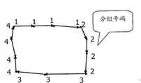
图15b示出了根据本实施方式的将多个关注区域特征点分为4个组的示例图,其中1,2,3和4分别表示分组号码。Fig. 15b shows an example diagram of dividing multiple ROI feature points into 4 groups according to this embodiment, where 1, 2, 3 and 4 represent group numbers respectively.
下面描述根据本发明一个实施方式的对分组后的各关注区域特征点进行的直线拟合,也就是进行一阶拟合的过程。The following describes the line fitting of the grouped feature points of the regions of interest according to an embodiment of the present invention, that is, the process of performing first-order fitting.
在对各关注区域特征点进行了分组之后,可以使用一条直线来拟合每个分组中的关注区域特征点,也就是对每个分组中的关注区域特征点进行一阶的直线拟合。设拟合第i个分组的直线为After the feature points of each region of interest are grouped, a straight line can be used to fit the feature points of the region of interest in each group, that is, a first-order straight line fitting is performed on the feature points of the region of interest in each group. Let the straight line fitting the i-th group be
y=kix+zi (20)y=ki x+zi (20)
其中ki为该直线的斜率,zi为该直线的平移,利用两个点的坐标即可计算出ki和zi。此处将不再详细描述。Among them,ki is the slope of the straight line,zi is the translation of the straight line, andki andzi can be calculated by using the coordinates of two points. It will not be described in detail here.
那么拟合所形成的多边形的顶点可以确定为:Then the vertices of the polygon formed by the fit can be determined as:
如果i=1,则If i=1, then
否则otherwise
图16示出了上述实施方式的拟合为四边形的一个关注区域的示例。该四边形中,定位设备只需要通过四个点(Vx,1,Vy,1)、(Vx,2,Vy,2)、(Vx,3,Vy,3)和(Vx,4,Vy,4)的坐标即可对该非规则形状的关注区域进行表征。FIG. 16 shows an example of a region of interest fitted to a quadrilateral in the above embodiment. In this quadrilateral, the positioning device only needs to pass through four points (Vx, 1 , Vy, 1 ), (Vx, 2 , Vy, 2 ), (Vx, 3 , Vy, 3 ) and (V The coordinates ofx, 4 , Vy, 4 ) can characterize the irregularly shaped attention region.
根据本发明的另一实施方式,还可以利用高阶的曲线拟合对各分组中的关注区域特征点进行拟合。例如,3阶的曲线拟合方程可以表示为:According to another embodiment of the present invention, high-order curve fitting can also be used to fit the feature points of the region of interest in each group. For example, the curve fitting equation of
y=a0+a1x+a2x2+a3x3(23)y=a0 +a1 x+a2 x2 +a3 x3 (23)
需要四个点的坐标即可求出系数a0-a3的值。通过高阶的曲线拟合,可以得出对特征区域进行更精确的表征,这样付出的代价是需要记录更多的特征点。当然,本发明并不局限于方程式(23)所示出的拟合曲线,而是可以使用其它的拟合曲线。曲线拟合对于本领域技术人员而言是很熟悉的,因此这里将不再详述。The values of the coefficients a0 -a3 can be obtained by needing the coordinates of four points. Through high-order curve fitting, a more accurate characterization of the feature area can be obtained, and the price paid is that more feature points need to be recorded. Of course, the present invention is not limited to the fitting curve shown in equation (23), but other fitting curves may be used. Curve fitting is well known to those skilled in the art and therefore will not be described in detail here.
当然,也可以将获取的各关注区域特征点用直线直接连接起来,形成如图15b所示的关注区域。需要指出的是,将各点直接连接实际上是拟合过程的一种特例,这在上文已进行了阐述。Of course, the acquired feature points of the ROIs can also be directly connected with a straight line to form the ROI as shown in FIG. 15b. It should be pointed out that directly connecting the points is actually a special case of the fitting process, which has been explained above.
根据本发明的另一实施方式,如图17所示,提供一种用于表征空间中的关注区域的设备600,该设备可以包括:接收装置610,用于接收能够表征关注区域的关注区域特征点的位置参数,其中位置参数是利用布置在空间中的定位设备获得的;以及表征装置620,用于根据所述位置参数来表征所述关注区域。表征620的工作过程与图10-16所描述的根据关注区域特征点的位置参数来表征所述关注区域的方式相同。According to another embodiment of the present invention, as shown in FIG. 17 , there is provided a
根据本发明的一个实施方式,当所述关注区域为非规则形状时,接收装置610进一步接收关注区域边界上的至少三个关注区域特征点的位置参数,以构成特征点序列;以及表征装置620进一步包括用于对所述特征点序列进行拟合来表征关注区域的装置。可选地,用于对所述特征点序列进行拟合的装置可以包括:用于将所述特征点序列进行分组的装置;以及用于拟合被分到同一组的所述关注区域特征点的装置。According to an embodiment of the present invention, when the region of interest has an irregular shape, the receiving means 610 further receives position parameters of at least three feature points of the region of interest on the boundary of the region of interest to form a sequence of feature points; and the characterizing means 620 It further includes means for fitting the sequence of feature points to characterize the region of interest. Optionally, the means for fitting the sequence of feature points may include: means for grouping the sequence of feature points; and for fitting the feature points of the region of interest grouped into the same group installation.
根据本发明的一个实施方式,用于将所述特征点序列进行分组的装置包括:用于比较关注区域特征点所确定的直线的斜率差绝对值是否小于预定阈值的装置,以及用于如果斜率差的绝对值小于预定阈值,则将这些关注区域特征点分为一组的装置。According to one embodiment of the present invention, the means for grouping the sequence of feature points includes: means for comparing whether the absolute value of the slope difference of the straight line determined by the feature points of the region of interest is less than a predetermined threshold, and means for if the slope If the absolute value of the difference is less than a predetermined threshold, then the feature points of these regions of interest are grouped into one group.
同样,该设备600可以集成在定位设备520中,也可以集成在服务器530中。Likewise, the
根据本发明实施方式的设备200、400和600可以通过软件、硬件、固件、电路、DSP以及他们的组合等各种方式来实现。The
根据本发明的一个实施方式,如图18所示,还提供一种用于对空间中的定位设备进行标定的方法700,其中,该空间中的一个或者多个位置点被选择作为空间特征点。该方法700可以包括:在步骤S710,接收空间特征点相对于定位设备自身的相对坐标;以及在步骤S720,根据所述相对坐标来确定所述定位设备在所述空间中的位置参数,从而标定所述定位设备。According to an embodiment of the present invention, as shown in FIG. 18 , a
根据本发明的优选实施方式,在所述空间特征点处放置有能够发射测距信号的标签,所述相对坐标是所述定位设备根据来自标签的所述测距信号获取的。这样可以实现测量的自动化。According to a preferred embodiment of the present invention, a tag capable of transmitting a ranging signal is placed at the spatial feature point, and the relative coordinates are acquired by the positioning device according to the ranging signal from the tag. This enables the automation of measurements.
根据本发明的另一实施方式,如图19所示,提供一种用于对定位设备进行标定的方法800,该方法可以包括:在S810,接收一个或者多个位置点在空间中的绝对坐标以及所述位置点相对于所述定位设备的相对坐标;以及在S820,根据所述绝对坐标和所述相对坐标来确定所述定位设备在所述空间中的位置参数,从而标定所述定位设备。According to another embodiment of the present invention, as shown in FIG. 19 , a method 800 for calibrating a positioning device is provided, which may include: at S810, receiving absolute coordinates of one or more position points in space and the relative coordinates of the position point relative to the positioning device; and at S820, determine the position parameters of the positioning device in the space according to the absolute coordinates and the relative coordinates, so as to calibrate the positioning device .
根据本发明的优选实施方式,所述位置点位于所述定位设备和已标定的另一定位设备的重叠覆盖区域中,在所述位置点处放置有能够发射测距信号的标签,所述相对坐标是所述定位设备根据来自标签的测距信号获取的,以及所述绝对坐标是所述另一定位设备根据来自标签的测距信号获取的。According to a preferred embodiment of the present invention, the location point is located in the overlapping coverage area of the positioning device and another calibrated positioning device, a tag capable of transmitting ranging signals is placed at the location point, and the relative The coordinates are obtained by the positioning device according to the ranging signal from the tag, and the absolute coordinates are obtained by the other positioning device according to the ranging signal from the tag.
根据本发明的又一实施方式,如图20所示,提供一种用于表征空间中的关注区域的方法900,该方法900可以包括:在步骤910,接收能够表征关注区域的关注区域特征点的位置参数,其中所述位置参数是利用布置在空间中的定位设备获得的;以及,在步骤920,根据所述位置参数,来表征所述关注区域。According to yet another embodiment of the present invention, as shown in FIG. 20 , a
根据本发明的一个实施方式,所述位置参数是所述关注区域特征点在空间中的绝对坐标置或所述关注区域特征点相对于定位设备的相对坐标。According to an embodiment of the present invention, the position parameter is the absolute coordinate position of the feature point of the region of interest in space or the relative coordinate of the feature point of the region of interest relative to the positioning device.
根据本发明的一个实施方式,当所述关注区域为圆形时,所述关注区域特征点为所述圆形的圆心和圆形周边的任意点。According to an embodiment of the present invention, when the ROI is a circle, the feature point of the ROI is the center of the circle and any point on the circumference of the circle.
根据本发明的一个实施方式,当所述关注区域为多边形时,所述关注区域特征点为所述多边形的顶点。According to an embodiment of the present invention, when the region of interest is a polygon, the feature points of the region of interest are vertices of the polygon.
根据本发明的一个实施方式,当所述关注区域为椭圆形时,所述关注区域特征点为所述椭圆的中心点、所述椭圆的长轴与该椭圆边的交点和所述椭圆的短轴与该椭圆边的交点。According to an embodiment of the present invention, when the region of interest is an ellipse, the feature points of the region of interest are the center point of the ellipse, the intersection of the major axis of the ellipse and the side of the ellipse, and the shortest point of the ellipse. The intersection point of the axis with the edge of this ellipse.
根据本发明的另一个实施方式,当所述关注区域为非规则形状时,该方法可以包括:接收关注区域边界上的至少三个关注区域特征点的位置参数,所述至少三个关注区域特征点构成特征点序列;对所述特征点序列进行拟合,以表征该关注区域。According to another embodiment of the present invention, when the region of interest is irregular in shape, the method may include: receiving position parameters of at least three region of interest feature points on the boundary of the region of interest, the at least three region of interest feature points The points form a sequence of feature points; the sequence of feature points is fitted to characterize the attention area.
根据本发明的一个实施方式,将所述特征点序列进行拟合包括:将所述特征点直接连接起来。According to an embodiment of the present invention, fitting the sequence of feature points includes: directly connecting the feature points.
根据本发明的优选实施方式,将所述特征点序列进行拟合包括:将所述特征点序列进行分组;以及,拟合被分到同一组的所述关注区域特征点。According to a preferred embodiment of the present invention, fitting the sequence of feature points includes: grouping the sequence of feature points; and fitting the feature points of the region of interest classified into the same group.
根据本发明的优选实施方式,将所述特征点序列进行分组包括:比较关注区域特征点所确定的直线的斜率差的绝对值是否小于预定阈值,如果斜率差的绝对值小于预定阈值,则将这些关注区域特征点分为一组。According to a preferred embodiment of the present invention, grouping the sequence of feature points includes: comparing whether the absolute value of the slope difference of the straight line determined by the feature points of the region of interest is less than a predetermined threshold; if the absolute value of the slope difference is less than a predetermined threshold, then the These region-of-interest feature points are grouped into one group.
根据本发明的实施方式,所述拟合包括一阶直线拟合算法或者高阶曲线拟合算法。According to an embodiment of the present invention, the fitting includes a first-order straight line fitting algorithm or a high-order curve fitting algorithm.
本发明的方法和设备可以在软件、硬件、或软件和硬件的结合中实现。硬件部分可以利用专用逻辑来实现;软件部分可以存储在存储器中,由适当的指令执行系统,例如微处理器、个人计算机(PC)或大型机来执行。The methods and devices of the present invention can be implemented in software, hardware, or a combination of software and hardware. The hardware part can be implemented using dedicated logic; the software part can be stored in memory and executed by a suitable instruction execution system such as a microprocessor, personal computer (PC) or mainframe.
提供本发明的说明书的目的是为了说明和描述,而不是用来穷举或将本发明限制为所公开的形式。对本领域的普通技术人员而言,许多修改和变更都是显而易见的。The description of the present invention has been presented for purposes of illustration and description, not exhaustive or limited to the invention in the form disclosed. Many modifications and changes will be apparent to those of ordinary skill in the art.
因此,选择并描述实施方式是为了更好地解释本发明的原理及其实际应用,并使本领域普通技术人员明白,在不脱离本发明实质的前提下,所有修改和变更均落入由权利要求所限定的本发明的保护范围之内。Therefore, the embodiment is selected and described in order to better explain the principle of the present invention and its practical application, and to make those skilled in the art understand that all modifications and changes fall within the scope of the patent rights without departing from the essence of the present invention. within the scope of protection of the present invention as defined by the requirements.
Claims (3)
Priority Applications (4)
| Application Number | Priority Date | Filing Date | Title |
|---|---|---|---|
| CN2009100020771ACN101782639B (en) | 2009-01-16 | 2009-01-16 | Method, device and system for calibrating a positioning device |
| JP2009279842AJP5101593B2 (en) | 2009-01-16 | 2009-12-09 | POSITIONING DEVICE CALIBRATION METHOD, DEVICE AND SYSTEM |
| US12/634,266US8306769B2 (en) | 2009-01-16 | 2009-12-09 | Method, device and system for calibrating positioning device |
| US13/557,754US8694275B2 (en) | 2009-01-16 | 2012-07-25 | Method, device and system for calibrating positioning device |
Applications Claiming Priority (1)
| Application Number | Priority Date | Filing Date | Title |
|---|---|---|---|
| CN2009100020771ACN101782639B (en) | 2009-01-16 | 2009-01-16 | Method, device and system for calibrating a positioning device |
Related Child Applications (1)
| Application Number | Title | Priority Date | Filing Date |
|---|---|---|---|
| CN201210407035.8ADivisionCN102937707B (en) | 2009-01-16 | 2009-01-16 | For the method, apparatus and system to calibrating positioning device |
Publications (2)
| Publication Number | Publication Date |
|---|---|
| CN101782639A CN101782639A (en) | 2010-07-21 |
| CN101782639Btrue CN101782639B (en) | 2013-11-27 |
Family
ID=42337616
Family Applications (1)
| Application Number | Title | Priority Date | Filing Date |
|---|---|---|---|
| CN2009100020771AExpired - Fee RelatedCN101782639B (en) | 2009-01-16 | 2009-01-16 | Method, device and system for calibrating a positioning device |
Country Status (3)
| Country | Link |
|---|---|
| US (2) | US8306769B2 (en) |
| JP (1) | JP5101593B2 (en) |
| CN (1) | CN101782639B (en) |
Families Citing this family (27)
| Publication number | Priority date | Publication date | Assignee | Title |
|---|---|---|---|---|
| CN101852847B (en)* | 2009-04-02 | 2013-12-04 | 日电(中国)有限公司 | Method, equipment and system for determining space regions of targets |
| US9477302B2 (en) | 2012-08-10 | 2016-10-25 | Google Inc. | System and method for programing devices within world space volumes |
| US20150153715A1 (en)* | 2010-09-29 | 2015-06-04 | Google Inc. | Rapidly programmable locations in space |
| CN102707286A (en)* | 2011-03-28 | 2012-10-03 | 日电(中国)有限公司 | Three-dimensional positioning system, node, host computer and operating method thereof |
| CN102279384A (en)* | 2011-04-25 | 2011-12-14 | 上海路歌信息技术有限公司 | Indoor infrared positioning system based on wireless function |
| JP5974445B2 (en)* | 2011-10-12 | 2016-08-23 | 富士ゼロックス株式会社 | Information processing apparatus and information processing program |
| CN103024661A (en)* | 2012-11-12 | 2013-04-03 | 上海斐讯数据通信技术有限公司 | Wireless location method and system |
| US10203683B2 (en) | 2013-07-16 | 2019-02-12 | Seagate Technology Llc | Coordinating end effector and vision controls |
| US20150287295A1 (en) | 2014-04-02 | 2015-10-08 | Tyco Fire & Security Gmbh | Smart Emergency Exit Signs |
| CN104199038B (en)* | 2014-09-15 | 2016-08-24 | 吉林大学 | A kind of ultrasonic wireless displacement measurement method in analog capsule cabin and system |
| US10849205B2 (en) | 2015-10-14 | 2020-11-24 | Current Lighting Solutions, Llc | Luminaire having a beacon and a directional antenna |
| KR101690781B1 (en)* | 2016-03-04 | 2016-12-29 | 주식회사 에센코 | Method for Configuring Region of Interest of Radar Monitoring System and Apparatus Therefor |
| CN106313119B (en)* | 2016-09-14 | 2019-05-03 | 哈工大机器人集团上海有限公司 | A kind of road sign for determining robot location, device |
| DE102017210481A1 (en)* | 2017-02-02 | 2018-08-02 | Robert Bosch Gmbh | Method for calibrating ultrasonic transducers and arrangement for carrying out the method |
| CN107053219B (en)* | 2017-06-16 | 2019-07-09 | 齐鲁工业大学 | A kind of method for positioning mobile robot based on laser scanner Yu strong reflecting sign |
| CN107864509A (en)* | 2017-10-18 | 2018-03-30 | 重庆玖舆博泓科技有限公司 | A large number of users method for rapidly positioning and its device |
| WO2019187259A1 (en)* | 2018-03-28 | 2019-10-03 | 日本電産株式会社 | Positioning system, positioning method, and adjustment method for positioning system |
| CN109188382B (en)* | 2018-07-27 | 2020-11-06 | 惠州华阳通用电子有限公司 | Target identification method based on millimeter wave radar |
| CN110927708B (en)* | 2018-08-30 | 2022-10-11 | 阿波罗智能技术(北京)有限公司 | Calibration method, device and equipment of intelligent road side unit |
| CN110189322B (en)* | 2019-06-04 | 2021-11-19 | 广州视源电子科技股份有限公司 | Flatness detection method, device, equipment, storage medium and system |
| CN110261824B (en)* | 2019-07-15 | 2024-03-19 | 交通运输部天津水运工程科学研究所 | Ultrashort baseline calibration system and calibration method based on multiple beacons |
| CN111024036B (en)* | 2019-12-31 | 2024-09-13 | 广东海工建设工程有限公司 | Wharf displacement monitoring device |
| CN112558007A (en)* | 2020-11-30 | 2021-03-26 | 北京金坤科创技术有限公司 | Accurate positioning method |
| CN112558051A (en)* | 2020-11-30 | 2021-03-26 | 湖南傲英创视信息科技有限公司 | Photoelectric pod stable platform passive distance measurement method based on UKF |
| CN113982276B (en)* | 2021-11-03 | 2023-03-14 | 广东天凛高新科技有限公司 | Method and device for accurately positioning cast-in-place wall robot |
| CN118056385A (en) | 2022-01-18 | 2024-05-17 | 三星电子株式会社 | Method and electronic device for intelligent home control |
| CN116261101A (en)* | 2023-01-10 | 2023-06-13 | 浙江大华技术股份有限公司 | Method and device for determining position of monitoring equipment, storage medium and electronic device |
Citations (3)
| Publication number | Priority date | Publication date | Assignee | Title |
|---|---|---|---|---|
| CN1488076A (en)* | 2001-01-05 | 2004-04-07 | Ħ��������˾ | Method and apparatus for position estimation |
| WO2004051304A1 (en)* | 2002-12-04 | 2004-06-17 | Sonitor Technologies As | Ultrasonic tracking and locating system |
| JP2008107251A (en)* | 2006-10-26 | 2008-05-08 | Matsushita Electric Works Ltd | Position detecting system |
Family Cites Families (9)
| Publication number | Priority date | Publication date | Assignee | Title |
|---|---|---|---|---|
| JPS58208606A (en)* | 1982-05-29 | 1983-12-05 | Nippon Telegr & Teleph Corp <Ntt> | Three dimensional position measuring method |
| JPH08271619A (en)* | 1995-03-28 | 1996-10-18 | Oki Electric Ind Co Ltd | Radar information calibration apparatus |
| US8611919B2 (en)* | 2002-05-23 | 2013-12-17 | Wounder Gmbh., Llc | System, method, and computer program product for providing location based services and mobile e-commerce |
| JP5513706B2 (en)* | 2006-08-24 | 2014-06-04 | パナソニック株式会社 | Position detection system |
| US20080074264A1 (en) | 2006-09-19 | 2008-03-27 | Teletech Holdings, Inc. | Product information associated with customer location |
| JP2008118256A (en)* | 2006-11-01 | 2008-05-22 | Mitsukuni Ito | Cognitive psycho-patient protective system |
| JP4569584B2 (en)* | 2007-03-09 | 2010-10-27 | パナソニック電工株式会社 | Flow line measurement system |
| JP2008299592A (en) | 2007-05-31 | 2008-12-11 | Hitachi Ltd | Radio wave area drawing creation method, program, and recording medium |
| JP4987799B2 (en)* | 2008-05-26 | 2012-07-25 | 日本電信電話株式会社 | Moving object position estimation method and moving object position estimation system |
- 2009
- 2009-01-16CNCN2009100020771Apatent/CN101782639B/ennot_activeExpired - Fee Related
- 2009-12-09JPJP2009279842Apatent/JP5101593B2/ennot_activeExpired - Fee Related
- 2009-12-09USUS12/634,266patent/US8306769B2/ennot_activeExpired - Fee Related
- 2012
- 2012-07-25USUS13/557,754patent/US8694275B2/ennot_activeExpired - Fee Related
Patent Citations (3)
| Publication number | Priority date | Publication date | Assignee | Title |
|---|---|---|---|---|
| CN1488076A (en)* | 2001-01-05 | 2004-04-07 | Ħ��������˾ | Method and apparatus for position estimation |
| WO2004051304A1 (en)* | 2002-12-04 | 2004-06-17 | Sonitor Technologies As | Ultrasonic tracking and locating system |
| JP2008107251A (en)* | 2006-10-26 | 2008-05-08 | Matsushita Electric Works Ltd | Position detecting system |
Also Published As
| Publication number | Publication date |
|---|---|
| JP5101593B2 (en) | 2012-12-19 |
| US8694275B2 (en) | 2014-04-08 |
| US20120290256A1 (en) | 2012-11-15 |
| US20100185408A1 (en) | 2010-07-22 |
| CN101782639A (en) | 2010-07-21 |
| JP2010175536A (en) | 2010-08-12 |
| US8306769B2 (en) | 2012-11-06 |
Similar Documents
| Publication | Publication Date | Title |
|---|---|---|
| CN101782639B (en) | Method, device and system for calibrating a positioning device | |
| Goldoni et al. | Experimental analysis of RSSI-based indoor localization with IEEE 802.15. 4 | |
| Luo et al. | Comparative evaluation of Received Signal-Strength Index (RSSI) based indoor localization techniques for construction jobsites | |
| CN103905992B (en) | Indoor positioning method based on wireless sensor networks of fingerprint data | |
| JP5226023B2 (en) | System, method and apparatus for determining an abnormal displacement of a positioning device | |
| US9883351B2 (en) | Indoor positioning device and indoor positioning method | |
| CN104053129A (en) | Wireless sensor network indoor positioning method and device based on sparse RF fingerprint interpolations | |
| CN103561380A (en) | Location fingerprint positioning method and device | |
| US7605756B2 (en) | System a method and an apparatus for performing wireless measurements, positioning and surface mapping by means of a portable coordinate system | |
| KR101537742B1 (en) | Beacon and Listner for Indoor Positioning System | |
| US20220229947A1 (en) | Artificial intelligence based exchange of geospatial related digital content | |
| US20220164492A1 (en) | Methods and apparatus for two dimensional location based digital content | |
| Alippi et al. | A RF map-based localization algorithm for indoor environments | |
| CN101788660B (en) | System, method and equipment for determining whether positioning equipment in space is moved or not | |
| CN119450357B (en) | Positioning method based on weight factors and WKNN | |
| CN102937707B (en) | For the method, apparatus and system to calibrating positioning device | |
| Neges et al. | Improving indoor location tracking quality for construction and facility management | |
| Zhao et al. | Autonomous ultrasonic indoor tracking system | |
| JP2020529600A (en) | Electronic devices, methods and computer programs for determining and using distances that rely on matching constellation information | |
| KR101317338B1 (en) | Apparatus for measuring indoor wave environment and method for measuring indoor wave environment using the same | |
| Dong et al. | Interior time-frequency domain sensor positioning in strong mobility-oriented human-centric wsns | |
| CN207249101U (en) | A vision-based radio direction finding device | |
| Orujov et al. | Comparative analysis of the indoor positioning algorithms using bluetooth low energy beacons | |
| Ariffin et al. | Indoor Location Based Tracking using Euclidean Distance Estimation (LTS-ED) | |
| Tang et al. | Comparative Analysis of Trilateration and Fingerprinting for Wi-Fi-Based Human Localization |
Legal Events
| Date | Code | Title | Description |
|---|---|---|---|
| C06 | Publication | ||
| PB01 | Publication | ||
| C10 | Entry into substantive examination | ||
| SE01 | Entry into force of request for substantive examination | ||
| C14 | Grant of patent or utility model | ||
| GR01 | Patent grant | ||
| CF01 | Termination of patent right due to non-payment of annual fee | ||
| CF01 | Termination of patent right due to non-payment of annual fee | Granted publication date:20131127 Termination date:20170116 |