CN101778981A - Door handle device - Google Patents
Door handle deviceDownload PDFInfo
- Publication number
- CN101778981A CN101778981ACN200880025574ACN200880025574ACN101778981ACN 101778981 ACN101778981 ACN 101778981ACN 200880025574 ACN200880025574 ACN 200880025574ACN 200880025574 ACN200880025574 ACN 200880025574ACN 101778981 ACN101778981 ACN 101778981A
- Authority
- CN
- China
- Prior art keywords
- command
- housing
- door handle
- door
- electrode
- Prior art date
- Legal status (The legal status is an assumption and is not a legal conclusion. Google has not performed a legal analysis and makes no representation as to the accuracy of the status listed.)
- Granted
Links
Images


Classifications
- B—PERFORMING OPERATIONS; TRANSPORTING
- B60—VEHICLES IN GENERAL
- B60R—VEHICLES, VEHICLE FITTINGS, OR VEHICLE PARTS, NOT OTHERWISE PROVIDED FOR
- B60R25/00—Fittings or systems for preventing or indicating unauthorised use or theft of vehicles
- E—FIXED CONSTRUCTIONS
- E05—LOCKS; KEYS; WINDOW OR DOOR FITTINGS; SAFES
- E05B—LOCKS; ACCESSORIES THEREFOR; HANDCUFFS
- E05B81/00—Power-actuated vehicle locks
- E05B81/54—Electrical circuits
- E05B81/64—Monitoring or sensing, e.g. by using switches or sensors
- E05B81/76—Detection of handle operation; Detection of a user approaching a handle; Electrical switching actions performed by door handles
- E05B81/78—Detection of handle operation; Detection of a user approaching a handle; Electrical switching actions performed by door handles as part of a hands-free locking or unlocking operation
- E—FIXED CONSTRUCTIONS
- E05—LOCKS; KEYS; WINDOW OR DOOR FITTINGS; SAFES
- E05B—LOCKS; ACCESSORIES THEREFOR; HANDCUFFS
- E05B85/00—Details of vehicle locks not provided for in groups E05B77/00 - E05B83/00
- E05B85/10—Handles
- E05B85/14—Handles pivoted about an axis parallel to the wing
- E05B85/16—Handles pivoted about an axis parallel to the wing a longitudinal grip part being pivoted at one end about an axis perpendicular to the longitudinal axis of the grip part
- E—FIXED CONSTRUCTIONS
- E05—LOCKS; KEYS; WINDOW OR DOOR FITTINGS; SAFES
- E05B—LOCKS; ACCESSORIES THEREFOR; HANDCUFFS
- E05B77/00—Vehicle locks characterised by special functions or purposes
- E05B77/34—Protection against weather or dirt, e.g. against water ingress
- E—FIXED CONSTRUCTIONS
- E05—LOCKS; KEYS; WINDOW OR DOOR FITTINGS; SAFES
- E05B—LOCKS; ACCESSORIES THEREFOR; HANDCUFFS
- E05B81/00—Power-actuated vehicle locks
- E05B81/54—Electrical circuits
- E05B81/64—Monitoring or sensing, e.g. by using switches or sensors
- E05B81/76—Detection of handle operation; Detection of a user approaching a handle; Electrical switching actions performed by door handles
- E05B81/77—Detection of handle operation; Detection of a user approaching a handle; Electrical switching actions performed by door handles comprising sensors detecting the presence of the hand of a user
- Y—GENERAL TAGGING OF NEW TECHNOLOGICAL DEVELOPMENTS; GENERAL TAGGING OF CROSS-SECTIONAL TECHNOLOGIES SPANNING OVER SEVERAL SECTIONS OF THE IPC; TECHNICAL SUBJECTS COVERED BY FORMER USPC CROSS-REFERENCE ART COLLECTIONS [XRACs] AND DIGESTS
- Y10—TECHNICAL SUBJECTS COVERED BY FORMER USPC
- Y10T—TECHNICAL SUBJECTS COVERED BY FORMER US CLASSIFICATION
- Y10T292/00—Closure fasteners
- Y10T292/57—Operators with knobs or handles
Landscapes
- Engineering & Computer Science (AREA)
- Mechanical Engineering (AREA)
- Lock And Its Accessories (AREA)
Abstract
Translated fromChinese
Description
Translated fromChinese技术领域technical field
本发明涉及具有检测车门的锁定指令等功能的门把手装置。The present invention relates to a door handle device having functions such as detecting a locking command of a vehicle door.
背景技术Background technique
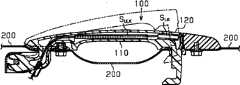
近年来,提供有搭载所谓的智能钥匙系统(smart entry system)(注册商标)的门把手装置。所述智能钥匙系统例如通过车辆使用者携带的携带机与车辆的发送接收机之间的通信认识到车辆使用者的接近和下车,并检测由车辆使用者发出的锁定指令和解锁指令从而自动执行车门的锁定和解锁。以往,作为这种门把手装置例如公知有专利文献1所记载的装置。图5中示出专利文献1所记载的门把手装置的正面构造。图6中示出沿着图5的6-6线的截面构造。In recent years, a door handle device equipped with a so-called smart entry system (registered trademark) has been provided. The smart key system, for example, recognizes the vehicle user's approach and getting off the vehicle through communication between the vehicle user's portable device and the vehicle's transmitter receiver, and detects the locking and unlocking commands issued by the vehicle user to automatically Carry out locking and unlocking of the doors. Conventionally, as such a door handle device, for example, a device described in Patent Document 1 is known. FIG. 5 shows the front structure of the door handle device described in Patent Document 1. As shown in FIG. FIG. 6 shows a cross-sectional configuration along line 6-6 of FIG. 5 .
如图5和图6所示,门把手装置的门把手100包含把持部110,该把持部110与车门的外面板200一起形成车辆使用者的手能够插入的部位。在该把持部110上设有用于检测由车辆使用者发出的解锁指令的解锁传感器SULK。用于对车门的开闭机构进行操作的操作部从上述门把手100的一方的端部120贯通外面板200延伸到门的内部。在该端部120上设有用于检测由车辆使用者发出的锁定指令的锁定传感器SLK。锁定传感器SLK和解锁传感器SULK均是检测静电电容的变化的静电电容式传感器,并且包含检测用电极。传感器SLK、SULK分别检测由于车辆使用者的手接近对应的检测用电极而产生的静电电容的变化,从而判断是发出了锁定指令还是解锁指令。例如,在设车门的外面板200与锁定传感器SLK的检测用电极之间的静电电容的基准值为CPANEL的情况下,在由该锁定传感器SLK检测到的静电电容的值与基准值CPANEL没有太大差别的情况下判断为并未发出锁定指令。在车辆使用者的手接近该检测用电极的情况下,在该检测用电极与车辆使用者的手之间形成有与上述静电电容CPANEL电并联的新的静电电容CT(合成静电电容CPANEL+CT)。因此,合成静电电容的值比基准值CPANEL超出与静电电容CT相当的量,据此判断为发出了锁定指令。该检测原理在解锁传感器SULK中也同样。在专利文献1的门把手装置中,锁定传感器SLK和解锁传感器SULK设在门把手100的不同部位。因此,能够通过车辆使用者接触门把手100的这些不同部位进行锁定指令和解锁指令的识别。As shown in FIGS. 5 and 6 , the
在专利文献1的门把手装置中,如图6所示,在把持部110端部的靠外表面的部位(与外面板200相反侧的部位)配设有锁定检测用电极(锁定传感器SLK)。因此,当车辆的使用者为了进行解锁操作而将手插入把持部110与外面板200之间,且为了打开车门而进行拉拽门把手100的操作时,手容易进入锁定传感器SLK的检测范围。在该情况下,同时进行基于解锁传感器SULK的解锁指令的检测和基于锁定传感器SLK的锁定指令的检测,存在无法进行准确的检测的可能性。并且,当门打开时,由于车辆使用者的手进入锁定传感器SLK的检测范围而进行锁定动作等,存在引发车辆使用者不期望的动作的可能性。In the door handle device of Patent Document 1, as shown inFIG. ). Therefore, when the user of the vehicle inserts his hand between the
专利文献1:日本特许第3502848号公报Patent Document 1: Japanese Patent No. 3502848
发明内容Contents of the invention
本发明的目的在于提供一种当车辆使用者进行车辆的锁定时能够避免引发误操作的门把手装置。An object of the present invention is to provide a door handle device capable of avoiding an erroneous operation when a vehicle user locks the vehicle.
为了达成上述目的,在本发明的一个方式中提供一种门把手装置,该门把手装置设在车门上,能够对车辆的门开闭机构进行操作。该门把手装置具备支承部件、门把手、锁定检测用电极、以及静电电容式传感器。上述支承部件设于上述门的外面板的内侧。上述门把手设于上述外面板的外侧,并且具有第一端部、第二端部、转动部、以及操作部。上述转动部从上述第一端部贯通上述外面板延伸,以便由上述支承部件支承为能够转动。上述操作部以能够对所述开闭机构进行操作的方式从上述第二端部贯通所述外面板而延伸。上述锁定检测用电极以与上述外面板静电电容耦合的方式设于上述门把手。上述静电电容式传感器与上述锁定检测用电极连接,并根据上述外面板与锁定检测用电极之间的静电电容的变化检测发出了门锁定指令。上述门把手具有第一把手壳体和第二把手壳体。上述第一把手壳体具有把持部,该把持部以与上述外面板的外侧面之间形成空隙的方式设置。上述第二把手壳体覆盖上述第一把手壳体,以形成上述门把手的外侧部。上述第二把手壳体具有相互对置的上壁和下壁。上述锁定检测用电极被设置为接近上述上壁和上述下壁的至少一方的内侧面并与之对置。上述锁定检测用电极由具有防水性的弹性体围绕。In order to achieve the above objects, one aspect of the present invention provides a door handle device provided on a vehicle door and capable of operating a door opening and closing mechanism of the vehicle. This door handle device includes a support member, a door handle, an electrode for lock detection, and a capacitive sensor. The said support member is provided in the inner side of the outer panel of the said door. The door handle is provided on the outer side of the outer panel, and has a first end, a second end, a rotating part, and an operating part. The rotation portion extends from the first end portion through the outer panel so as to be rotatably supported by the support member. The operation portion extends from the second end portion through the outer panel so that the opening and closing mechanism can be operated. The lock detection electrode is provided on the door handle so as to be capacitively coupled to the outer panel. The capacitive sensor is connected to the lock detection electrode, and issues a door lock command based on detection of a change in capacitance between the outer panel and the lock detection electrode. The above door handle has a first handle case and a second handle case. The first handle housing has a grip portion provided to form a gap with the outer surface of the outer panel. The second handle case covers the first handle case to form an outer side of the door handle. The second handle housing has an upper wall and a lower wall opposite to each other. The lock detection electrode is provided close to and opposed to an inner surface of at least one of the upper wall and the lower wall. The lock detection electrode is surrounded by a waterproof elastic body.
在本发明的另一个方式中提供一种门把手装置,该门把手装置设在车门上,以能够对车辆的门开闭机构进行操作。该门把手装置包含第一把手壳体、第二把手壳体、锁定检测用电极、以及弹性体。上述第一把手壳体具有把持部,该把持部以与上述外面板的外侧面之间形成空隙的方式设置。上述第二把手壳体以覆盖上述第一把手壳体的方式安装于第一把手壳体。上述锁定检测用电极设在上述第一把手壳体与上述第二把手壳体之间,且以能够根据与上述外面板之间的静电电容的变化检测门锁定指令的方式与上述外面板静电电容耦合。上述锁定检测用电极具有与上述外面板对置的电极端部。上述弹性体覆盖上述电极端部且具有防水性。Another aspect of the present invention provides a door handle device provided on a vehicle door so as to be able to operate a door opening and closing mechanism of the vehicle. This door handle device includes a first handle case, a second handle case, a lock detection electrode, and an elastic body. The first handle housing has a grip portion provided to form a gap with the outer surface of the outer panel. The second handle case is attached to the first handle case so as to cover the first handle case. The lock detection electrode is provided between the first handle case and the second handle case, and is capacitively coupled to the outer panel in such a manner that a door lock command can be detected based on a change in capacitance with the outer panel. . The lock detection electrode has an electrode end facing the outer panel. The elastic body covers the end of the electrode and is waterproof.
附图说明Description of drawings
图1是本发明的一个实施方式所涉及的门把手装置的剖视图。FIG. 1 is a cross-sectional view of a door handle device according to an embodiment of the present invention.
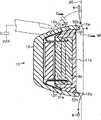
图2是示出图1的门把手装置的从第一端部到把持部的部分的分解构造的立体图。Fig. 2 is a perspective view illustrating an exploded structure of a portion from a first end portion to a grip portion of the door handle device of Fig. 1 .
图3是主要示出图1的门把手装置的门锁定系统的结构的框图。FIG. 3 is a block diagram mainly showing the structure of a door locking system of the door handle device of FIG. 1 .
图4是沿着图1的4-4线的剖视图。Fig. 4 is a sectional view taken along line 4-4 of Fig. 1 .
图5是以往的门把手装置的主视图。Fig. 5 is a front view of a conventional door handle device.
图6是沿着图5的6-6线的剖视图。Fig. 6 is a cross-sectional view along line 6-6 of Fig. 5 .
具体实施方式Detailed ways
以下,参照图1~图4对搭载有智能钥匙系统(注册商标)的本发明所涉及的门把手装置的一个实施方式进行说明。Hereinafter, an embodiment of a door handle device according to the present invention equipped with a smart key system (registered trademark) will be described with reference to FIGS. 1 to 4 .
如图1所示,能够对车辆的门开闭机构进行操作的门把手装置具备门把手10,该门把手10包含由第一把手壳体11和第二把手壳体12构成的壳体。上述第一把手壳体11具有由车辆使用者把持的把持部11a。该把持部11a在与车门的外面板20的外侧面之间形成空隙GP。上述第二把手壳体12通过螺钉等紧固于上述第一把手壳体11,以覆盖上述第一把手壳体11,从而形成上述门把手10的外侧部。如上所述,门把手10的壳体由两个分割体(11、12)构成。因此,门把手10具有设计和制造上的高自由度和高便利性。第一把手壳体11和第二把手壳体12都由具有高刚性的树脂材料形成。As shown in FIG. 1 , a door handle device capable of operating a door opening and closing mechanism of a vehicle includes a
在上述外面板20的内部设有支承部件21和上述门开闭机构的杆22。上述第二把手壳体12具有:作为第一部分的第一端部12b;以及作为第二部分的第二端部12d,其从该第一端部12b夹着上述把持部11a位于相反侧。转动部12a从第一端部12b贯通上述外面板20延伸到外面板20的内部并由上述支承部件21支承为能够转动。对上述杆22进行操作的操作部12c从上述第二端部12d贯通上述外面板20延伸到外面板20的内部。当车辆使用者在把持把持部11a的状态下以拉拽门把手10的方式进行操作时,门把手10以第一端部12b作为转动中心朝第二端部12d被拉出的方向转动。此时,如果车门不是锁定状态,就能够通过操作部12c对杆22进行操作从而使车门敞开。Inside the
在第一把手壳体11中,在把持部11a和第一端部12b之间搭载有电路基板30,在该电路基板30上安装有各种电子部件。如图4所示,在把手壳体11内填充有柔软的树脂(例如聚氨酯、硅胶等)90,电路基板30通过上述树脂90被固定于壳体11且被防水。另外,该树脂90仅在图4中示出。在电路基板30上安装有一对锁定检测用电极31。该锁定检测用电极31与静电电容式传感器41连接,该静电电容式传感器41根据静电电容的变化检测发出了车门的门锁定指令的情况。如图2和图4所示,各锁定检测用电极31与第二把手壳体12的内表面、更详细地说是第二把手壳体12的上下壁12e、12f的各自的内侧面对置,并且配置于把持部11a与第一端部12b之间。此处,图4中的上下与车辆的上下方向对应。在本实施方式中,锁定检测用电极31接近上下壁12e、12f的各自的内侧面,具体而言为接触。静电电容式传感器42的解锁检测用电极32与设于电路基板30的作为传感器输入端子的特定电极电连接。该解锁检测用电极32根据静电电容的变化检测发出了车门的门解锁指令的情况。该解锁检测用电极32设在把持部11a的内部。在把持部11a的内部设有天线33。在天线33与车辆使用者所携带的携带机(未图示)之间发送接收包含使用者认证等的必要信息。天线33与设在电路基板30上的作为供电端子的特定电极电连接。在电路基板30上安装有包含上述静电电容式传感器41、42的传感器IC 40。对传感器IC 40以及天线33等的供电、以及门控制部60(参照图3)对包含来自该传感器IC 40的输出信号的各种必要信息的取得都经由设在电路基板30的背面的连接器34进行。In the
上述两个锁定检测用电极31由橡胶或弹性材料等具有防水性的弹性体50围绕。弹性体50嵌装于上述第一把手壳体11的外侧面或者第二把手壳体12的内侧面。图2中示出弹性体50及其周边部分的具体构造。The two
如图2所示,锁定检测用电极31以关于在上下壁12e、12f之间的中央从上述第一端部12b朝向第二端部12d沿着门把手10的长度方向延伸的中心线m对称的方式设置。上述弹性体50沿着锁定检测用电极31的外形设置。具体而言,上述弹性体50具有:第一部分51,其配设于电路基板30与第二把手壳体12的内表面之间;以及一对第二部分52,其从第一部分51开始在第一和第二把手壳体11、12之间以沿着锁定检测用电极31的外形的方式延伸。弹性体50形成为关于上述中心线m对称的形状。在第一部分51和各第二部分52之间形成有开口部53。当组装所述弹性体50时,各锁定检测用电极31插入于各个开口部53。由此,各锁定检测用电极31由第一部分51的外侧壁51a和第二部分52的内侧壁52a围绕。第一部分51包含外缘部分51b和内缘部分51c。在组装门把手10后的状态下,图2中的弹性体50的上表面与第二把手壳体12的内表面抵接,并且,各第二部分52由第一把手壳体11和第二把手壳体12的相互对置的面夹持(参照图4)。锁定检测用电极31具有电极端部31a,该电极端部31a以与上述外面板20对置的方式位于第一把手壳体11和第二把手壳体12之间的间隙中。所述第二部分52在该电极端部31a与外面板20之间堵塞第一把手壳体11和第二把手壳体12之间的间隙。优选第二部分52的外面板侧端部52b形成为与第一把手壳体11的外面板侧端部11b或者第二把手壳体12的外面板侧端部12g共面。这样,上述弹性体50在锁定检测用电极31的周围堵塞第一把手壳体11和第二把手壳体12之间的间隙。As shown in FIG. 2 , the
图3主要以框图示出门把手装置中的门锁定系统的等价电路。以下,参照图3对门锁定所涉及的检测原理以及动作概要进行说明。FIG. 3 mainly shows an equivalent circuit of a door locking system in a door handle device in a block diagram. Hereinafter, the detection principle and operation outline related to door locking will be described with reference to FIG. 3 .
在图3中,以接地GND1表示外面板20。如该图3所示,外面板20和锁定检测用电极31以在二者之间具有静电电容CPANEL的方式静电电容耦合。静电电容CPANEL的值经由锁定检测用电极31被静电电容式传感器41取得。此处,假定车辆使用者的手接触第二把手壳体12的与锁定检测用电极31对置的部分。在图3中,以接地GND 2表示车辆使用者。此时,车辆使用者和锁定检测用电极31以在二者之间具有静电电容CT的方式静电电容耦合。该静电电容CT与上述静电电容CPANEL处于存在电并联的关系。静电电容式传感器41中取得表示合成静电电容(CPANEL+CT)的值。根据该合成静电电容的值比静电电容CPANEL超出与静电电容CT相当的值,据此,静电电容式传感器41检测到发出了门锁定指令。由此,门控制部60根据来自静电电容式传感器41的检测信号判断为车辆使用者发出了门锁定指令。进而,门控制部60经由驱动电路70驱动设于锁定机构80的锁定用致动器81从而锁定车门。上述检测原理和动作概要在通过解锁检测用电极32和静电电容式传感器42的协作对车门进行解锁的解锁系统中也同样。如上所述,各锁定检测用电极31以与第二把手壳体12的上下壁12e、12f的各自的内侧面对置的方式设置。因此,消除了因车辆使用者的通常对门把手把持操作而发出门锁定指令的担忧。即,避免了引发车辆使用者进行的与门锁定相关的误操作。In FIG. 3 , the
下面,对在以上述方式构成的门把手装置中设置弹性体50的意义进行说明。即,如图4所示,由于与第一端部12b和把持部11a之间对应的部分相当于门把手10中的转动基端,因此该部分与外面板20之间的间隙狭窄。当下雨等时雨滴W容易被导入至第一和第二把手壳体11、12与外面板之间并滞留。并且,由于门把手10的壳体由分割的两个把手壳体11、12构成,因此存在该被导入的雨滴W浸入第二把手壳体12的内侧面,且浸入的雨滴W接近锁定检测用电极31或者与其接触的担忧。进而,当浸入的雨滴W接近锁定检测用电极31或者与其接触时,在静电电容耦合的该检测用电极31与外面板20的对置部中、特别是二者的间隔最短的最短对置部中,伴随着电介质的介电常数的增大,静电电容增大与CPANEL(W)相当的量。由此,增大的静电电容CPANEL(W)会对检测用电极31与外面板20之间的静电电容CPANEL造成的影响变大。因此,就像发出上述门锁定指令那样,有可能引起静电电容式传感器41的误动作。Next, the significance of providing the
在本实施方式所涉及的门把手装置中,锁定检测用电极31由具有防水性的弹性体50围绕。因此,如图4所示,可靠地遮断了雨滴W相对于第二把手壳体12内侧面的浸入。由此,抑制了锁定检测用电极31与外面板20之间的最短对置部处的介电常数的增大,进而抑制了该静电电容CPANEL(W)的增大。因此,恰当地抑制了由雨滴W的浸入等引起的静电电容式传感器41、42的误动作等。除此之外,在本实施方式中,至少在锁定检测用电极31的周围,弹性体50堵塞第一把手壳体11与第二把手壳体12之间的间隙。因此,避免了雨滴W相对于锁定检测用电极31周围的浸入和滞留,因此更加可靠地抑制了静电电容式传感器41的误动作。In the door handle device according to the present embodiment, the
根据本实施方式所涉及的门把手装置能够得到以下的优点。According to the door handle device according to this embodiment, the following advantages can be obtained.
(1)将锁定检测用电极31设于第二把手壳体12的上下壁12e、12f的各自的内侧面。由此,消除了根据车辆使用者的通常的门把手把持操作发出门锁定指令等担忧。进一步,利用具有防水性的弹性体围绕锁定检测用电极31。由此,能够避免雨滴W浸入第二把手壳体12的内侧面、以及浸入的雨滴W接近锁定检测用电极31或者与锁定检测用电极31接触等。因此,抑制了由于雨滴W的浸入等引起的所述锁定检测用电极31与外面板20之间的最短对置部处的介电常数的增大,进而抑制了静电电容成分CPANEL(W)的增大。其结果是,恰当地抑制了静电电容式传感器41的误动作等。(1) The
(2)围绕锁定检测用电极31的弹性体50的部位夹持在第一把手壳体11和第二把手壳体12之间。由此,第一把手壳体11和第二把手壳体12之间的间隙在锁定检测用电极31的周围被密闭,因此避免了雨滴W浸入锁定检测用电极31周围的情况。因此,抑制了由于雨滴的浸入引起的静电电容式传感器的误动作。(1)和(2)的优点并不限于由降雨引起的雨滴W,例如对于通过洗车等附着的水滴等也同样起作用。(2) The portion of the
(3)一对锁定检测用电极31关于从第一端部12b朝第二端部12d延伸的中心线m对称,围绕这些锁定检测用电极31的弹性体50也关于上述中心线m对称。即,在门把手被安装于车门的状态下,两个锁定检测用电极31以上下对称的方式设置。因此,该门把手装置被标准化,能够通用地使用。具体而言,对车辆的右侧的门、左侧的门、或者车辆后部的门等任一个门都能够通用地使用基本为同一构造的门把手装置。(3) The pair of
(4)作为具有防水性的弹性体50采用作为密封材料通用地使用的橡胶或者弹性材料。因此,容易实现上述的防水构造。(4) As the waterproof
(5)将车门的解锁检测用电极32设于门把手的把持部11a的内部。因此,根据车辆使用者为了敞开车门而对门把手进行把持操作的情况发出门解锁指令。因此,能够恰当地区分门锁定指令和门解锁指令。即,能够通过各静电电容式传感器41、42更加准确地检测车辆使用者的与车门的锁定/解锁相关的意思。(5) The door
(6)另外,优选第二部分52的外面板侧端部52b与第一把手壳体11的外面板侧端部11b或者第二把手壳体12的外面板侧端部12g共面。由此,在锁定检测用电极31的周围,利用弹性体50堵塞第一把手壳体11和第二把手壳体12之间的间隙。(6) In addition, it is preferable that the outer-panel-
另外,上述实施方式也能够以适当变更后的以下的方式实施。In addition, the above-mentioned embodiment can also be implemented in the following forms suitably modified.
在上述实施方式中,弹性体50采用橡胶或弹性材料,但是,只要是具有防水性的弹性体即可,也可以适当采用其他的树脂材料等。In the above-described embodiment, rubber or an elastic material is used for the
在上述实施方式中,至少在锁定检测用电极31的周围,利用弹性体50堵塞第一把手壳体11和第二把手壳体12之间的间隙。但是,例如对于具有雨滴等难以滞留的构造的门把手,仅利用具有防水性的弹性体围绕该锁定检测用电极31的周围,即可得到与上述实施方式同样的优点。In the above-described embodiment, at least around the
锁定检测用电极31并非必须以上下对称的方式设置。例如在锁定检测用电极为单一的电极的情况下,只要设在门把手的把持部与第一端部之间即可,在门把手安装于车辆的状态中,锁定检测用电极可以设在与门把手的上壁和下壁中的任一个的内侧面对置的位置。The
在上述实施方式中,第一端部12b和第二端部12d设于第二把手壳体12,但是,第一端部12b和第二端部12d中的至少一方也可以设于第一把手壳体11。In the above embodiment, the
在上述实施方式中,弹性体50也可以通过粘接安装于上述第一把手壳体11或者上述第二把手壳体12。In the above embodiment, the
权利要求书(按照条约第19条的修改)Claims (as amended under Article 19 of the Treaty)
1.(修改后)一种门把手装置,其设在车门上,能够对车辆的门开闭机构进行操作,所述门把手装置的特征在于,具备:1. (Modified) A door handle device, which is arranged on a vehicle door and can operate the door opening and closing mechanism of the vehicle, said door handle device is characterized in that it has:
第一把手壳体,其具有把持部,该把持部以与车门的外面板的外侧面之间形成空隙的方式设置;A first handle housing, which has a grip part, and the grip part is arranged in a manner to form a gap with the outer surface of the outer panel of the vehicle door;
第二把手壳体,其以覆盖所述第一把手壳体的方式安装于所述第一把手壳体;a second handle housing mounted on the first handle housing in such a manner as to cover the first handle housing;
锁定检测用电极,其设在所述第一把手壳体与所述第二把手壳体之间,且以能够根据与所述外面板之间的静电电容的变化检测门锁定指令的方式与所述外面板静电电容耦合,该锁定检测用电极具有与所述外面板对置的电极端部;An electrode for lock detection provided between the first handle case and the second handle case, and connected to the door lock command in such a manner that a door lock command can be detected based on a change in capacitance between the outer panel and the outer panel. The outer panel is electrostatically capacitively coupled, and the locking detection electrode has an electrode end opposite to the outer panel;
电路基板,其设于所述第一把手壳体;以及a circuit substrate provided on the first handle case; and
弹性体,其覆盖所述电极端部且具有防水性,an elastomer covering the electrode ends and having water repellency,
所述弹性体具有:第一部分,其配设于所述电路基板与所述第二把手壳体的内表面之间;以及第二部分,其从第一部分开始以沿着所述锁定检测用电极的外形的方式延伸,并且,所述弹性体在所述第一部分与所述第二部分之间具有开口部,所述锁定检测用电极配置于该开口部。The elastic body has: a first portion disposed between the circuit board and an inner surface of the second handle case; and a second portion extending from the first portion along the lock detection electrode. In addition, the elastic body has an opening between the first part and the second part, and the lock detection electrode is arranged in the opening.
2.(修改后)根据权利要求1所述的门把手装置,其特征在于,2. (After modification) The door handle device according to claim 1, characterized in that,
所述电极端部位于所述第一把手壳体与所述第二把手壳体之间的间隙,所述弹性体在所述电极端部和所述外面板之间以堵塞所述间隙的方式设置。The electrode end is located in a gap between the first handle housing and the second handle housing, and the elastic body is arranged between the electrode end and the outer panel to block the gap .
3.(修改后)根据权利要求1或2所述的门把手装置,其特征在于,3. (After modification) The door handle device according to claim 1 or 2, characterized in that,
所述弹性体嵌装于所述第一把手壳体或者所述第二把手壳体。The elastic body is embedded in the first handle housing or the second handle housing.
4.(修改后)根据权利要求1或2所述的门把手装置,其特征在于,4. (After modification) The door handle device according to claim 1 or 2, characterized in that,
所述弹性体粘接于所述第一把手壳体或者所述第二把手壳体。The elastic body is adhered to the first handle shell or the second handle shell.
5.(修改后)根据权利要求1~4中的任一项所述的门把手装置,其特征在于,5. (After modification) The door handle device according to any one of claims 1 to 4, characterized in that,
所述弹性体由橡胶或者弹性材料形成。The elastic body is formed of rubber or elastic material.
6.(删除)6. (deleted)
7.(删除)7. (deleted)
8.(删除)8. (deleted)
9.(删除)9. (deleted)
10.(删除)10. (deleted)
11.(删除)11. (deleted)
12.(删除)12. (deleted)
13.(删除)13. (deleted)
14.(删除)14. (deleted)
15.(删除)15. (deleted)
Claims (15)
Applications Claiming Priority (3)
| Application Number | Priority Date | Filing Date | Title |
|---|---|---|---|
| JP2007196119AJP4751860B2 (en) | 2007-07-27 | 2007-07-27 | Door handle device |
| JP196119/2007 | 2007-07-27 | ||
| PCT/JP2008/063388WO2009017048A1 (en) | 2007-07-27 | 2008-07-25 | Door handle device |
Publications (2)
| Publication Number | Publication Date |
|---|---|
| CN101778981Atrue CN101778981A (en) | 2010-07-14 |
| CN101778981B CN101778981B (en) | 2012-11-28 |
Family
ID=40304278
Family Applications (1)
| Application Number | Title | Priority Date | Filing Date |
|---|---|---|---|
| CN2008800255747AExpired - Fee RelatedCN101778981B (en) | 2007-07-27 | 2008-07-25 | Door handle device |
Country Status (5)
| Country | Link |
|---|---|
| US (1) | US20100187838A1 (en) |
| EP (1) | EP2172605B1 (en) |
| JP (1) | JP4751860B2 (en) |
| CN (1) | CN101778981B (en) |
| WO (1) | WO2009017048A1 (en) |
Cited By (9)
| Publication number | Priority date | Publication date | Assignee | Title |
|---|---|---|---|---|
| CN102477817A (en)* | 2010-11-26 | 2012-05-30 | 爱信精机株式会社 | Door handle apparatus |
| CN103080451A (en)* | 2010-09-22 | 2013-05-01 | 爱信精机株式会社 | Vehicle door handle device |
| CN104238644A (en)* | 2013-06-19 | 2014-12-24 | 联想(北京)有限公司 | Unlocking method and electronic device |
| CN105209702A (en)* | 2012-10-04 | 2015-12-30 | Adac塑模公司 | Release handle assembly with inertial blocking member |
| CN106050019A (en)* | 2016-07-29 | 2016-10-26 | 奇瑞新能源汽车技术有限公司 | Vehicle door outer handle mounting structure |
| CN106193835A (en)* | 2016-07-29 | 2016-12-07 | 奇瑞新能源汽车技术有限公司 | A kind of outside door handle installation method |
| CN111051629A (en)* | 2017-09-05 | 2020-04-21 | 法国大陆汽车公司 | Device for detecting the intention of a user to lock or unlock a motor vehicle door and associated door handle |
| CN115419334A (en)* | 2017-12-05 | 2022-12-02 | Adac塑模公司 | Door handle assembly for motor vehicle |
| CN115552090A (en)* | 2020-06-24 | 2022-12-30 | 阿尔卑斯阿尔派株式会社 | door handle device |
Families Citing this family (18)
| Publication number | Priority date | Publication date | Assignee | Title |
|---|---|---|---|---|
| JP4938580B2 (en) | 2007-07-27 | 2012-05-23 | アイシン精機株式会社 | Door handle device |
| JP4751861B2 (en) | 2007-07-27 | 2011-08-17 | アイシン精機株式会社 | Door handle device |
| JP4751860B2 (en)* | 2007-07-27 | 2011-08-17 | アイシン精機株式会社 | Door handle device |
| JP5131472B2 (en) | 2008-07-24 | 2013-01-30 | アイシン精機株式会社 | Door handle device |
| IT1396932B1 (en)* | 2009-11-20 | 2012-12-20 | Valeo Spa | COMMAND DEVICE FOR RELEASING THE HANDLE OF A VEHICLE WITH AN EXTERNAL COMMAND ORGAN. |
| JP5022483B2 (en) | 2010-07-26 | 2012-09-12 | アイシン精機株式会社 | Vehicle door handle device |
| DE102011002105A1 (en)* | 2011-04-15 | 2012-10-18 | Huf Hülsbeck & Fürst Gmbh & Co. Kg | An automobile door handle |
| US9957737B2 (en) | 2012-06-29 | 2018-05-01 | Ford Global Technologies, Llc | Flush-mounted door handle for vehicles |
| US8701353B2 (en) | 2012-06-29 | 2014-04-22 | Ford Global Technologies, Llc | Deployable door handle for vehicles |
| JP6064806B2 (en)* | 2013-06-21 | 2017-01-25 | アイシン精機株式会社 | Vehicle door handle |
| JP5958939B2 (en)* | 2013-07-25 | 2016-08-02 | 株式会社ホンダロック | Vehicle door handle device |
| JP6651710B2 (en)* | 2015-05-08 | 2020-02-19 | 三井金属アクト株式会社 | Door lock device for automobile |
| CN105059242A (en)* | 2015-08-06 | 2015-11-18 | 黄进平 | Automobile window and door prying and stealing preventing device |
| JP6698160B2 (en)* | 2016-07-08 | 2020-05-27 | 本田技研工業株式会社 | Door structure |
| DE102016116885A1 (en)* | 2016-09-08 | 2018-03-08 | Huf Hülsbeck & Fürst Gmbh & Co. Kg | Door handle of a vehicle |
| US10907388B2 (en)* | 2017-08-31 | 2021-02-02 | Nissan North America, Inc. | Vehicle door handle assembly |
| US10962496B2 (en)* | 2019-05-30 | 2021-03-30 | Semiconductor Components Industries, Llc | Methods and apparatus for water detection using a capacitive sensor |
| USD1061204S1 (en)* | 2023-09-01 | 2025-02-11 | Volvo Truck Corporation | Door handle |
Family Cites Families (46)
| Publication number | Priority date | Publication date | Assignee | Title |
|---|---|---|---|---|
| DE19617038C2 (en)* | 1996-04-27 | 2000-11-30 | Huf Huelsbeck & Fuerst Gmbh | Locking system, in particular for motor vehicles |
| IT1305154B1 (en)* | 1998-11-03 | 2001-04-10 | Valeo Sicurezza Abitacolo Spa | HANDLE FOR A VEHICLE DOOR. |
| JP3648396B2 (en)* | 1998-12-02 | 2005-05-18 | トヨタ自動車株式会社 | Vehicle door handle |
| ES2244453T3 (en)* | 1999-07-27 | 2005-12-16 | HUF HULSBECK & FURST GMBH & CO. KG | EXTERNAL DOOR HANDLE, ESPECIALLY FOR VEHICLES. |
| DE10015887C1 (en)* | 2000-03-30 | 2002-01-17 | Huf Huelsbeck & Fuerst Gmbh | Access system for a vehicle |
| JP2002057564A (en)* | 2000-08-11 | 2002-02-22 | Aisin Seiki Co Ltd | Human body detector |
| FR2813630B1 (en)* | 2000-09-05 | 2003-08-01 | Valeo Electronique | METHOD FOR AUTOMATICALLY LOCKING A VEHICLE OPENING ELEMENT WITH A HANDS-FREE ACCESS SYSTEM AND AN APPROACH SENSOR |
| DE10051055A1 (en)* | 2000-10-14 | 2002-05-02 | Bosch Gmbh Robert | Device for initiating an opening and locking process of a motor vehicle |
| JP3502848B2 (en)* | 2001-03-28 | 2004-03-02 | 株式会社ホンダロック | Device for confirming vehicle door opening / locking |
| DE10132925A1 (en)* | 2001-06-12 | 2003-01-02 | Bosch Gmbh Robert | Exterior door handle assembly |
| JP3566943B2 (en)* | 2001-07-02 | 2004-09-15 | アイシン精機株式会社 | Vehicle door handle |
| DE60223405T2 (en)* | 2001-10-01 | 2008-08-21 | Donnelly Corp., Holland | VEHICLE GRIP ASSEMBLY WITH ANTENNA |
| JP3619505B2 (en)* | 2001-11-20 | 2005-02-09 | 株式会社ホンダロック | Vehicle door handle device |
| JP4003453B2 (en)* | 2001-12-26 | 2007-11-07 | アイシン精機株式会社 | Human body detection device |
| US20030216817A1 (en)* | 2002-05-16 | 2003-11-20 | Richard Pudney | Vehicle access system with sensor |
| JP3770218B2 (en)* | 2002-08-29 | 2006-04-26 | アイシン精機株式会社 | Human body detection device for vehicle door opening and method of using the same |
| JP4161664B2 (en)* | 2002-09-27 | 2008-10-08 | アイシン精機株式会社 | Vehicle door handle device |
| JP4084640B2 (en)* | 2002-11-20 | 2008-04-30 | 株式会社ホンダロック | Outdoor handle device for vehicle door |
| DE10255439B4 (en)* | 2002-11-28 | 2008-07-17 | Daimler Ag | Handle arrangement for a vehicle door |
| US7057124B2 (en)* | 2003-04-22 | 2006-06-06 | Aisin Seiki Kabushiki Kaisha | Push switch apparatus |
| US7931314B2 (en)* | 2003-06-20 | 2011-04-26 | Kabushiki Kaisha Honda Lock | Vehicle door outer handle system |
| EP1669520A1 (en)* | 2003-09-26 | 2006-06-14 | Matsushita Electric Industrial Co., Ltd. | Door handle device and keyless entry device having the same |
| DE10348719A1 (en)* | 2003-10-16 | 2005-05-12 | Huf Huelsbeck & Fuerst Gmbh | Outside door handle, especially for vehicles, contains transmission and excitation electrodes associated with capacitive locking and unlocking sensors |
| JP4098215B2 (en)* | 2003-10-29 | 2008-06-11 | アイシン精機株式会社 | Human body detection device for vehicle |
| JP4446769B2 (en)* | 2004-03-12 | 2010-04-07 | 株式会社ホンダロック | Outdoor handle device for vehicle door |
| DE602005021841D1 (en)* | 2004-03-30 | 2010-07-29 | Honda Lock Kk | Door handle assembly for a motor vehicle door |
| JP4052277B2 (en)* | 2004-04-19 | 2008-02-27 | アイシン精機株式会社 | Vehicle door handle device |
| DE102004026442A1 (en)* | 2004-05-29 | 2005-12-22 | Huf Hülsbeck & Fürst Gmbh & Co. Kg | Device for actuating an electrical or mechanical closing device on a door and / or a flap of a vehicle |
| JP4443307B2 (en)* | 2004-05-31 | 2010-03-31 | 株式会社アルファ | Door handle device |
| JP4240307B2 (en)* | 2004-06-22 | 2009-03-18 | アイシン精機株式会社 | Vehicle door opening and closing device |
| CN1973105B (en)* | 2004-06-23 | 2010-12-01 | 爱信精机株式会社 | vehicle handle |
| DE102004038569B3 (en)* | 2004-08-06 | 2005-10-20 | Huf Huelsbeck & Fuerst Gmbh | An automobile door handle |
| JP4428388B2 (en)* | 2004-09-28 | 2010-03-10 | アイシン精機株式会社 | Antenna device and door handle device |
| ATE398052T1 (en)* | 2005-06-29 | 2008-07-15 | Huf Huelsbeck & Fuerst Gmbh | LOCKING SYSTEM |
| JP4639141B2 (en)* | 2005-11-18 | 2011-02-23 | 株式会社ホンダロック | Antenna built-in device |
| JP2007138565A (en)* | 2005-11-18 | 2007-06-07 | Aisin Seiki Co Ltd | Vehicle door opening and closing device |
| JP4600323B2 (en)* | 2006-03-15 | 2010-12-15 | アイシン精機株式会社 | Vehicle door handle |
| DE602007000993D1 (en)* | 2006-03-16 | 2009-06-10 | Aisin Seiki | Door handle device for vehicles |
| JP4947348B2 (en)* | 2006-09-13 | 2012-06-06 | アイシン精機株式会社 | Vehicle door handle device |
| JP5078408B2 (en)* | 2007-03-30 | 2012-11-21 | 株式会社ホンダロック | Vehicle out-handle device |
| JP4751860B2 (en)* | 2007-07-27 | 2011-08-17 | アイシン精機株式会社 | Door handle device |
| JP4751861B2 (en)* | 2007-07-27 | 2011-08-17 | アイシン精機株式会社 | Door handle device |
| JP4938580B2 (en)* | 2007-07-27 | 2012-05-23 | アイシン精機株式会社 | Door handle device |
| JP5324816B2 (en)* | 2008-05-08 | 2013-10-23 | アイシン精機株式会社 | Vehicle door handle |
| US8269615B2 (en)* | 2008-05-16 | 2012-09-18 | Aisin Seiki Kabushiki Kaisha | Door handle and locking system |
| JP5131472B2 (en)* | 2008-07-24 | 2013-01-30 | アイシン精機株式会社 | Door handle device |
- 2007
- 2007-07-27JPJP2007196119Apatent/JP4751860B2/ennot_activeExpired - Fee Related
- 2008
- 2008-07-25EPEP20080791632patent/EP2172605B1/ennot_activeNot-in-force
- 2008-07-25WOPCT/JP2008/063388patent/WO2009017048A1/enactiveApplication Filing
- 2008-07-25CNCN2008800255747Apatent/CN101778981B/ennot_activeExpired - Fee Related
- 2008-07-25USUS12/670,529patent/US20100187838A1/ennot_activeAbandoned
Cited By (13)
| Publication number | Priority date | Publication date | Assignee | Title |
|---|---|---|---|---|
| CN103080451A (en)* | 2010-09-22 | 2013-05-01 | 爱信精机株式会社 | Vehicle door handle device |
| CN102477817A (en)* | 2010-11-26 | 2012-05-30 | 爱信精机株式会社 | Door handle apparatus |
| CN105209702A (en)* | 2012-10-04 | 2015-12-30 | Adac塑模公司 | Release handle assembly with inertial blocking member |
| CN104238644A (en)* | 2013-06-19 | 2014-12-24 | 联想(北京)有限公司 | Unlocking method and electronic device |
| CN106050019B (en)* | 2016-07-29 | 2018-02-16 | 奇瑞新能源汽车技术有限公司 | A kind of outside door handle mounting structure |
| CN106193835A (en)* | 2016-07-29 | 2016-12-07 | 奇瑞新能源汽车技术有限公司 | A kind of outside door handle installation method |
| CN106050019A (en)* | 2016-07-29 | 2016-10-26 | 奇瑞新能源汽车技术有限公司 | Vehicle door outer handle mounting structure |
| CN111051629A (en)* | 2017-09-05 | 2020-04-21 | 法国大陆汽车公司 | Device for detecting the intention of a user to lock or unlock a motor vehicle door and associated door handle |
| CN111051629B (en)* | 2017-09-05 | 2021-06-29 | 法国大陆汽车公司 | Device for detecting the intention of a user to lock or unlock a motor vehicle door and associated door handle |
| CN115419334A (en)* | 2017-12-05 | 2022-12-02 | Adac塑模公司 | Door handle assembly for motor vehicle |
| CN115419334B (en)* | 2017-12-05 | 2024-03-26 | Adac塑模公司 | Door handle assembly for a motor vehicle |
| CN115552090A (en)* | 2020-06-24 | 2022-12-30 | 阿尔卑斯阿尔派株式会社 | door handle device |
| CN115552090B (en)* | 2020-06-24 | 2024-11-26 | 阿尔卑斯阿尔派株式会社 | Door handle device |
Also Published As
| Publication number | Publication date |
|---|---|
| JP4751860B2 (en) | 2011-08-17 |
| EP2172605B1 (en) | 2014-01-08 |
| US20100187838A1 (en) | 2010-07-29 |
| EP2172605A1 (en) | 2010-04-07 |
| WO2009017048A1 (en) | 2009-02-05 |
| EP2172605A4 (en) | 2012-11-28 |
| JP2009030358A (en) | 2009-02-12 |
| CN101778981B (en) | 2012-11-28 |
Similar Documents
| Publication | Publication Date | Title |
|---|---|---|
| CN101778981B (en) | Door handle device | |
| CN101778982B (en) | Door handle device | |
| CN101778983B (en) | Door handle device | |
| JP5131472B2 (en) | Door handle device | |
| JP5022483B2 (en) | Vehicle door handle device | |
| US7375299B1 (en) | Door handle | |
| US20120133159A1 (en) | Door handle apparatus | |
| CN1867747B (en) | Exterior door handle, in particular for a motor vehicle | |
| JP7618544B2 (en) | SENSOR SYSTEM FOR A MOVING PART OF A VEHICLE AND METHOD FOR DETECTING ACTIVATION OF A SENSOR SYSTEM - Patent application | |
| US20180252005A1 (en) | Power locking door handle with capacitive sensing | |
| US11402236B2 (en) | Device for detecting an intention to lock or unlock a door of a motor vehicle, comprising an electrode or target supported by a foam block | |
| CN109415916B (en) | door structure | |
| CN110325697B (en) | Motor vehicle door handle with means for detecting intent to lock and unlock a motor vehicle door | |
| CN108454563A (en) | Trailer reversing detection device | |
| CN1973105A (en) | Vehicle handle | |
| JP4079646B2 (en) | Vehicle door outside handle device | |
| KR101562355B1 (en) | A Touch Door Opening-Locking System for the Vehicles with Sub-Channel of Touch Sensors | |
| CN110177915B (en) | Handle device |
Legal Events
| Date | Code | Title | Description |
|---|---|---|---|
| C06 | Publication | ||
| PB01 | Publication | ||
| C10 | Entry into substantive examination | ||
| SE01 | Entry into force of request for substantive examination | ||
| C14 | Grant of patent or utility model | ||
| GR01 | Patent grant | ||
| CF01 | Termination of patent right due to non-payment of annual fee | Granted publication date:20121128 Termination date:20200725 | |
| CF01 | Termination of patent right due to non-payment of annual fee |