CN101778605A - Ablation in the gastrointestinal tract to achieve hemostasis and to cure wounds prone to bleeding - Google Patents
Ablation in the gastrointestinal tract to achieve hemostasis and to cure wounds prone to bleedingDownload PDFInfo
- Publication number
- CN101778605A CN101778605ACN200880102747ACN200880102747ACN101778605ACN 101778605 ACN101778605 ACN 101778605ACN 200880102747 ACN200880102747 ACN 200880102747ACN 200880102747 ACN200880102747 ACN 200880102747ACN 101778605 ACN101778605 ACN 101778605A
- Authority
- CN
- China
- Prior art keywords
- ablation
- energy
- tissue
- bleeding
- target
- Prior art date
- Legal status (The legal status is an assumption and is not a legal conclusion. Google has not performed a legal analysis and makes no representation as to the accuracy of the status listed.)
- Pending
Links
Images


Classifications
- A—HUMAN NECESSITIES
- A61—MEDICAL OR VETERINARY SCIENCE; HYGIENE
- A61B—DIAGNOSIS; SURGERY; IDENTIFICATION
- A61B18/00—Surgical instruments, devices or methods for transferring non-mechanical forms of energy to or from the body
- A61B18/04—Surgical instruments, devices or methods for transferring non-mechanical forms of energy to or from the body by heating
- A61B18/12—Surgical instruments, devices or methods for transferring non-mechanical forms of energy to or from the body by heating by passing a current through the tissue to be heated, e.g. high-frequency current
- A61B18/14—Probes or electrodes therefor
- A61B18/1492—Probes or electrodes therefor having a flexible, catheter-like structure, e.g. for heart ablation
- A—HUMAN NECESSITIES
- A61—MEDICAL OR VETERINARY SCIENCE; HYGIENE
- A61B—DIAGNOSIS; SURGERY; IDENTIFICATION
- A61B18/00—Surgical instruments, devices or methods for transferring non-mechanical forms of energy to or from the body
- A61B18/04—Surgical instruments, devices or methods for transferring non-mechanical forms of energy to or from the body by heating
- A61B18/12—Surgical instruments, devices or methods for transferring non-mechanical forms of energy to or from the body by heating by passing a current through the tissue to be heated, e.g. high-frequency current
- A61B18/14—Probes or electrodes therefor
- A61B18/1485—Probes or electrodes therefor having a short rigid shaft for accessing the inner body through natural openings
- A—HUMAN NECESSITIES
- A61—MEDICAL OR VETERINARY SCIENCE; HYGIENE
- A61B—DIAGNOSIS; SURGERY; IDENTIFICATION
- A61B18/00—Surgical instruments, devices or methods for transferring non-mechanical forms of energy to or from the body
- A61B18/02—Surgical instruments, devices or methods for transferring non-mechanical forms of energy to or from the body by cooling, e.g. cryogenic techniques
- A61B18/0218—Surgical instruments, devices or methods for transferring non-mechanical forms of energy to or from the body by cooling, e.g. cryogenic techniques with open-end cryogenic probe, e.g. for spraying fluid directly on tissue or via a tissue-contacting porous tip
- A—HUMAN NECESSITIES
- A61—MEDICAL OR VETERINARY SCIENCE; HYGIENE
- A61B—DIAGNOSIS; SURGERY; IDENTIFICATION
- A61B17/00—Surgical instruments, devices or methods
- A61B17/22—Implements for squeezing-off ulcers or the like on inner organs of the body; Implements for scraping-out cavities of body organs, e.g. bones; for invasive removal or destruction of calculus using mechanical vibrations; for removing obstructions in blood vessels, not otherwise provided for
- A61B2017/22051—Implements for squeezing-off ulcers or the like on inner organs of the body; Implements for scraping-out cavities of body organs, e.g. bones; for invasive removal or destruction of calculus using mechanical vibrations; for removing obstructions in blood vessels, not otherwise provided for with an inflatable part, e.g. balloon, for positioning, blocking, or immobilisation
- A61B2017/22065—Functions of balloons
- A61B2017/22069—Immobilising; Stabilising
- A—HUMAN NECESSITIES
- A61—MEDICAL OR VETERINARY SCIENCE; HYGIENE
- A61B—DIAGNOSIS; SURGERY; IDENTIFICATION
- A61B18/00—Surgical instruments, devices or methods for transferring non-mechanical forms of energy to or from the body
- A61B2018/00053—Mechanical features of the instrument of device
- A61B2018/0016—Energy applicators arranged in a two- or three dimensional array
- A—HUMAN NECESSITIES
- A61—MEDICAL OR VETERINARY SCIENCE; HYGIENE
- A61B—DIAGNOSIS; SURGERY; IDENTIFICATION
- A61B18/00—Surgical instruments, devices or methods for transferring non-mechanical forms of energy to or from the body
- A61B2018/00053—Mechanical features of the instrument of device
- A61B2018/00214—Expandable means emitting energy, e.g. by elements carried thereon
- A61B2018/0022—Balloons
- A—HUMAN NECESSITIES
- A61—MEDICAL OR VETERINARY SCIENCE; HYGIENE
- A61B—DIAGNOSIS; SURGERY; IDENTIFICATION
- A61B18/00—Surgical instruments, devices or methods for transferring non-mechanical forms of energy to or from the body
- A61B2018/00053—Mechanical features of the instrument of device
- A61B2018/00273—Anchoring means for temporary attachment of a device to tissue
- A61B2018/00279—Anchoring means for temporary attachment of a device to tissue deployable
- A61B2018/00285—Balloons
- A—HUMAN NECESSITIES
- A61—MEDICAL OR VETERINARY SCIENCE; HYGIENE
- A61B—DIAGNOSIS; SURGERY; IDENTIFICATION
- A61B18/00—Surgical instruments, devices or methods for transferring non-mechanical forms of energy to or from the body
- A61B2018/00315—Surgical instruments, devices or methods for transferring non-mechanical forms of energy to or from the body for treatment of particular body parts
- A61B2018/00482—Digestive system
- A61B2018/00494—Stomach, intestines or bowel
- A—HUMAN NECESSITIES
- A61—MEDICAL OR VETERINARY SCIENCE; HYGIENE
- A61B—DIAGNOSIS; SURGERY; IDENTIFICATION
- A61B18/00—Surgical instruments, devices or methods for transferring non-mechanical forms of energy to or from the body
- A61B2018/00571—Surgical instruments, devices or methods for transferring non-mechanical forms of energy to or from the body for achieving a particular surgical effect
- A61B2018/00577—Ablation
- A—HUMAN NECESSITIES
- A61—MEDICAL OR VETERINARY SCIENCE; HYGIENE
- A61B—DIAGNOSIS; SURGERY; IDENTIFICATION
- A61B18/00—Surgical instruments, devices or methods for transferring non-mechanical forms of energy to or from the body
- A61B2018/00636—Sensing and controlling the application of energy
- A61B2018/00642—Sensing and controlling the application of energy with feedback, i.e. closed loop control
- A61B2018/00654—Sensing and controlling the application of energy with feedback, i.e. closed loop control with individual control of each of a plurality of energy emitting elements
- A—HUMAN NECESSITIES
- A61—MEDICAL OR VETERINARY SCIENCE; HYGIENE
- A61B—DIAGNOSIS; SURGERY; IDENTIFICATION
- A61B18/00—Surgical instruments, devices or methods for transferring non-mechanical forms of energy to or from the body
- A61B2018/00636—Sensing and controlling the application of energy
- A61B2018/00696—Controlled or regulated parameters
- A61B2018/00702—Power or energy
- A—HUMAN NECESSITIES
- A61—MEDICAL OR VETERINARY SCIENCE; HYGIENE
- A61B—DIAGNOSIS; SURGERY; IDENTIFICATION
- A61B18/00—Surgical instruments, devices or methods for transferring non-mechanical forms of energy to or from the body
- A61B2018/00636—Sensing and controlling the application of energy
- A61B2018/00696—Controlled or regulated parameters
- A61B2018/00738—Depth, e.g. depth of ablation
- A—HUMAN NECESSITIES
- A61—MEDICAL OR VETERINARY SCIENCE; HYGIENE
- A61B—DIAGNOSIS; SURGERY; IDENTIFICATION
- A61B18/00—Surgical instruments, devices or methods for transferring non-mechanical forms of energy to or from the body
- A61B2018/00636—Sensing and controlling the application of energy
- A61B2018/00773—Sensed parameters
- A61B2018/00791—Temperature
- A—HUMAN NECESSITIES
- A61—MEDICAL OR VETERINARY SCIENCE; HYGIENE
- A61B—DIAGNOSIS; SURGERY; IDENTIFICATION
- A61B18/00—Surgical instruments, devices or methods for transferring non-mechanical forms of energy to or from the body
- A61B2018/00636—Sensing and controlling the application of energy
- A61B2018/00773—Sensed parameters
- A61B2018/00875—Resistance or impedance
- A—HUMAN NECESSITIES
- A61—MEDICAL OR VETERINARY SCIENCE; HYGIENE
- A61B—DIAGNOSIS; SURGERY; IDENTIFICATION
- A61B18/00—Surgical instruments, devices or methods for transferring non-mechanical forms of energy to or from the body
- A61B2018/00636—Sensing and controlling the application of energy
- A61B2018/00898—Alarms or notifications created in response to an abnormal condition
- A—HUMAN NECESSITIES
- A61—MEDICAL OR VETERINARY SCIENCE; HYGIENE
- A61B—DIAGNOSIS; SURGERY; IDENTIFICATION
- A61B18/00—Surgical instruments, devices or methods for transferring non-mechanical forms of energy to or from the body
- A61B18/02—Surgical instruments, devices or methods for transferring non-mechanical forms of energy to or from the body by cooling, e.g. cryogenic techniques
- A61B2018/0231—Characteristics of handpieces or probes
- A61B2018/0262—Characteristics of handpieces or probes using a circulating cryogenic fluid
- A—HUMAN NECESSITIES
- A61—MEDICAL OR VETERINARY SCIENCE; HYGIENE
- A61B—DIAGNOSIS; SURGERY; IDENTIFICATION
- A61B18/00—Surgical instruments, devices or methods for transferring non-mechanical forms of energy to or from the body
- A61B18/04—Surgical instruments, devices or methods for transferring non-mechanical forms of energy to or from the body by heating
- A61B18/12—Surgical instruments, devices or methods for transferring non-mechanical forms of energy to or from the body by heating by passing a current through the tissue to be heated, e.g. high-frequency current
- A61B18/1206—Generators therefor
- A61B2018/124—Generators therefor switching the output to different electrodes, e.g. sequentially
- A—HUMAN NECESSITIES
- A61—MEDICAL OR VETERINARY SCIENCE; HYGIENE
- A61B—DIAGNOSIS; SURGERY; IDENTIFICATION
- A61B18/00—Surgical instruments, devices or methods for transferring non-mechanical forms of energy to or from the body
- A61B18/04—Surgical instruments, devices or methods for transferring non-mechanical forms of energy to or from the body by heating
- A61B18/12—Surgical instruments, devices or methods for transferring non-mechanical forms of energy to or from the body by heating by passing a current through the tissue to be heated, e.g. high-frequency current
- A61B18/14—Probes or electrodes therefor
- A61B2018/1497—Electrodes covering only part of the probe circumference
Landscapes
- Health & Medical Sciences (AREA)
- Life Sciences & Earth Sciences (AREA)
- Surgery (AREA)
- Engineering & Computer Science (AREA)
- Plasma & Fusion (AREA)
- General Health & Medical Sciences (AREA)
- Otolaryngology (AREA)
- Physics & Mathematics (AREA)
- Veterinary Medicine (AREA)
- Biomedical Technology (AREA)
- Heart & Thoracic Surgery (AREA)
- Medical Informatics (AREA)
- Molecular Biology (AREA)
- Animal Behavior & Ethology (AREA)
- Nuclear Medicine, Radiotherapy & Molecular Imaging (AREA)
- Public Health (AREA)
- Cardiology (AREA)
- Surgical Instruments (AREA)
- Media Introduction/Drainage Providing Device (AREA)
Abstract
Description
Translated fromChinese相关申请的交叉引用Cross References to Related Applications
本申请要求Utley、Wallace和Gerberding等人于2007年7月6日提交的名称为“Non-Barrett’s Mucosal Ablation Disease Targets”、编号为60/958,566的美国临时申请的优先权。This application claims priority to U.S. Provisional Application No. 60/958,566, filed July 6, 2007, by Utley, Wallace, and Gerberding et al., entitled "Non-Barrett's Mucosal Ablation Disease Targets."
本申请包含以下共同转让的美国专利申请的整体:于2003年2月19日提交并于2003年8月21日公开为US2003/0158550的、名称为“Method of Treating Abnormal Tissue in the Human Esophagus”、序列号为10/370,645的美国专利申请;以及于2005年11月23日提交并于2007年5月24日公开为US2007/0118106的、名称为“PrecisionAblating Method”、序列号为11/286,444的美国专利申请。此外,下述共同转让的美国专利申请中的每一项其整体均通过引用包含于此:名称为“Systems and Methods for Treating Obesity and OtherGastrointestinal Conditions”、序列号为10/291,862的专利申请;名称为“Methods of Treating Abnormal Tissue In The HumanEsophagus”、序列号为10/370,645的专利申请;名称为“PrecisionAblating Device”、序列号为11/286,257的专利申请;名称为“Auto-Aligning Ablating Device and Method of Use”、序列号为11/275,244的专利申请;名称为“Precision Ablating Device”、序列号为11/286,444的专利申请;名称为“System for Tissue Ablation”、序列号为11/420,712的专利申请;名称为“Methods for CryogenicTissue Ablation”、序列号为11/420,714的专利申请;名称为“Methodsfor Vacuum-Assisted Tissue Ablation”、序列号为11/420,719的专利申请;名称为“Method for Tissue Ablation”、序列号为11/420,722的专利申请;名称为“Surgical Instruments and Techniques for TreatingGastro-Esophageal Reflux Disease”、序列号为11/469,816的专利申请。本申请还包括Kelly等人于2008年5月2日提交的名称为“Methodand Apparatus for Gastrointestinal Tract Ablation for Treatment ofObesity”且序列号为12/114,628的美国专利申请以及Wallace等人于2008年6月20日提交的名称为“Electrical Means to NormalizeAblational Energy Transmission to a Luminal Tissue Surface of VaryingSize”且序列号为12/143,404的美国专利申请的整体。This application incorporates the entirety of the following commonly assigned U.S. Patent Application: "Method of Treating Abnormal Tissue in the Human Esophagus", filed on February 19, 2003 and published as US2003/0158550 on August 21, 2003, U.S. Patent Application Serial No. 10/370,645; and U.S. Patent Application Serial No. 11/286,444, "Precision Ablating Method," filed November 23, 2005 and published May 24, 2007 as US2007/0118106 patent application. In addition, each of the following commonly assigned U.S. patent applications, serial number 10/291,862, entitled "Systems and Methods for Treating Obesity and Other Gastrointestinal Conditions," is hereby incorporated by reference in its entirety; Patent application serial number 10/370,645 for "Methods of Treating Abnormal Tissue In The Human Esophagus"; patent application serial number 11/286,257 titled "Precision Ablating Device"; patent application titled "Auto-Aligning Ablating Device and Method of Use ", serial number 11/275,244; patent application serial number 11/286,444 titled "Precision Ablating Device"; patent application serial number 11/420,712 titled "System for Tissue Ablation"; Patent Application Serial No. 11/420,714 for "Methods for Cryogenic Tissue Ablation"; Patent Application Serial No. 11/420,719 Titled "Methods for Vacuum-Assisted Tissue Ablation"; Patent Application 11/420,722; Patent Application Serial No. 11/469,816 entitled "Surgical Instruments and Techniques for Treating Gastro-Esophageal Reflux Disease". This application also includes U.S. Patent Application Serial No. 12/114,628, filed May 2, 2008 by Kelly et al., entitled "Method and Apparatus for Gastrointestinal Tract Ablation for Treatment of Obesity," and Wallace et al., filed June 20, 2008. The entirety of U.S. Patent Application Serial No. 12/143,404, entitled "Electrical Means to Normalize Ablational Energy Transmission to a Luminal Tissue Surface of VaryingSize," filed on .
说明书中所提到的所有出版物、专利和专利申请与分别明确地表示每个单独的出版物、专利或专利申请通过引用包含于此同样程度地通过引用包含于此。All publications, patents, and patent applications mentioned in this specification are herein incorporated by reference to the same extent as if each individual publication, patent, or patent application were specifically indicated to be incorporated by reference.
技术领域technical field
本发明涉及内窥镜治疗装置和方法,例如治疗患者消化道中具有消化道出血症状的区域以控制出血(实现止血)和/或根治倾向出血的创伤的装置和方法。The present invention relates to devices and methods for endoscopic treatment, eg, of a patient's alimentary canal of an area of the alimentary canal having symptoms of gastrointestinal bleeding to control bleeding (to achieve hemostasis) and/or to heal bleeding-prone wounds.
背景技术Background technique
消化道内腔可能出现消化道壁所包含的血管出血的现象。这种出血是异常的,且可能与一些疾病状态和解剖构造异常相关。当出现出血时,可能是伴随着吐血或直肠排血的急症。在这些情况下,通常需要紧急内窥镜或外科介入治疗,同时进行输血,以防止患者发病和死亡。这类实例包括:与门脉高压相关的食道内静脉曲张出血、胃或十二指肠溃疡内的血管暴露出血、或患疝气的肠内动静脉畸形(混乱的血管团)。Bleeding may occur in the lumen of the digestive tract from blood vessels contained in the walls of the digestive tract. This bleeding is abnormal and may be associated with some disease states and anatomical abnormalities. When bleeding occurs, it may be an emergency with vomiting or rectal discharge. In these cases, emergency endoscopic or surgical intervention, along with blood transfusion, is often required to prevent patient morbidity and mortality. Examples of this include bleeding from esophageal varices associated with portal hypertension, bleeding from exposed blood vessels in gastric or duodenal ulcers, or herniated intestinal arteriovenous malformations (disorganized clumps of blood vessels).
其他出血损伤可能表现为慢性的较不严重的出血,导致慢性贫血并需要连续的内窥镜介入治疗以烧灼可见异常。因为内窥镜介入对于永久性的停止出血并不理想,这些情况通常需要长期的输血治疗。这类实例包括:胃窦血管扩张症(GAVE),由于其特征性的胃损伤也被称为西瓜胃;辐射引发的直肠和结肠病症;门脉血压过高(PHG);血管发育异常;小动静脉畸形(AVM)和小出血溃疡。很多这种更慢性异常的常见现象是消化道壁特别是粘膜层和粘膜下层出现比正常更大、更脆、更靠近表面、缠结、无序且/或暴露于消化道内腔且因此比正常更容易被通过的食物或粪便损伤的血管。由于这些特征的组合,这些血管倾向于慢性地向消化道内腔出血,从而需要长期的管理。Other hemorrhagic injuries may manifest as chronic less severe bleeding, leading to chronic anemia and requiring serial endoscopic interventions to cauterize visible abnormalities. Because endoscopic intervention is not ideal for permanent cessation of bleeding, these conditions often require long-term transfusion therapy. Such examples include: gastric antrum vasectasis (GAVE), also known as watermelon stomach due to its characteristic gastric lesions; radiation-induced rectal and colonic disorders; portal hypertension (PHG); vascular dysplasia; Arteriovenous malformations (AVMs) and small bleeding ulcers. A common finding in many of these more chronic abnormalities is that the walls of the digestive tract, particularly the mucosa and submucosa, appear larger than normal, more brittle, closer to the surface, tangled, disordered, and/or exposed to the lumen of the digestive tract and thus appear larger than normal Blood vessels that are more likely to be damaged by passing food or stool. Due to the combination of these features, these vessels tend to bleed chronically into the lumen of the digestive tract, requiring long-term management.
患者吐血或从直肠排血并具有心血管效应程度的急性出血通常由内窥镜或外科治疗和输血进行紧急管理。一般地,这些情况与大血管破裂并向内腔大量出血相关。这些损伤可以由内窥镜观察到并且可以注射肾上腺素以减缓出血,然后由小探针直接接触血管来烧灼,或者可以由氩气的带电蒸汽来烧灼。这些探针传递快速加热作为目标病灶的血管或组织的超声波能量,于是血管萎缩并停止出血。外科手术保留用于发生不适于内窥镜治疗的危及生命的出血的患者。Acute bleeding of the magnitude of cardiovascular effects in patients with hematemesis or rectal discharge is usually urgently managed with endoscopic or surgical therapy and blood transfusion. Typically, these conditions are associated with rupture of a large vessel and massive hemorrhage into the lumen. These lesions can be visualized endoscopically and epinephrine can be injected to slow the bleeding, followed by cauterization with a small probe directly touching the blood vessel, or can be cauterized with electrically charged vapors of argon gas. These probes deliver ultrasound energy that rapidly heats the blood vessel or tissue that is the target lesion, so the blood vessel shrinks and bleeding stops. Surgery is reserved for patients with life-threatening bleeding not amenable to endoscopic therapy.
虽然慢性出血事件导致长期能力丧失并需要反复治疗和输血,但是一般并不需要紧急救生介入。相反,一般是当患者表现出不明原因的贫血时在内窥镜检查之后找到这些损伤。如上文所述,这些损伤对于内窥镜是可辨认并且可对准的。烧灼是希望能永久性地排除出血的风险的标准治疗。不幸的是在很多情况下,现有的烧灼技术不能永久性地根治这些损伤,且会恢复出血。造成现有烧灼方法的不满意结果的因素包括诸如GAVE、辐射引发的直肠和结肠病症、门脉血压过高(PHG)和血管发育异常等损伤倾向于表现出大范围损伤,不适于使用小探针压迫损伤处的烧灼技术的情况。甚至动静脉畸形倾向于具有高流量和更大的表面区域,难以使用小探针进行治疗。传统烧灼方法有问题且不稳定的另一个可能的原因与烧灼时血管组织中有血液有关。在治疗胃肠道急性和慢性出血领域中的系统与方法,特别是传统烧灼技术的非外科方法或改进,将是很受欢迎的。Although chronic bleeding episodes result in long-term disability and require repeated treatment and transfusions, urgent life-saving intervention is generally not required. Instead, these lesions are typically found after endoscopy when the patient exhibits unexplained anemia. These lesions are identifiable and registerable endoscopically, as described above. Caulterization is the standard treatment in hopes of permanently excluding the risk of bleeding. Unfortunately in many cases, current cautery techniques do not permanently heal these injuries and bleeding resumes. Factors contributing to the unsatisfactory results of existing cautery methods include lesions such as GAVE, radiation-induced rectal and colonic disorders, portal hypertension (PHG), and angiodysplasia, which tend to exhibit extensive damage and are unsuitable for the use of small probes. The case of cautery techniques at needle compression lesions. Even AVMs tend to have high flow and larger surface area, making them difficult to treat with small probes. Another possible reason for the problematic and inconsistent nature of traditional cautery methods has to do with blood in the vascular tissue when cauterized. Systems and methods in the field of treating acute and chronic bleeding from the gastrointestinal tract, particularly non-surgical methods or improvements to traditional cautery techniques, would be appreciated.
发明内容Contents of the invention
为了解决这些和其他需求,本发明提供一种内窥镜装置和方法的多种实施方式,通过提供更大的烧蚀表面、在传递烧灼能量之前压迫血管、并控制烧蚀深度以包括含有出血血管的组织层,以提供对消化道中所出现的主要慢性出血的更永久性的解决方案以及对导致这些出血的损伤的更永久性的根治。为了这个目的,该装置包括安装在内窥镜末端的基于囊的内窥镜导管,或者通过内窥镜的工作通道或附件通道的内窥镜导管。该装置在至少一个表面上具有电子阵列以将射频能量或其他能量源以通过诸如能量密度、电极图形、功率密度、施加次数和作用于组织的压强的参数控制烧蚀深度的方式提供至目标组织。通过线缆与导管相连的能量发生器将烧蚀能量提供至导管。To address these and other needs, the present invention provides various embodiments of an endoscopic device and method by providing a larger ablation surface, compressing the blood vessel prior to delivery of ablation energy, and controlling ablation depth to include bleeding The tissue layer of blood vessels to provide a more permanent solution to major chronic bleeding that occurs in the digestive tract and a more permanent cure of the damage that caused these bleeding. For this purpose, the device comprises a balloon-based endoscopic catheter mounted at the tip of the endoscope, or an endoscopic catheter passed through the working or accessory channel of the endoscope. The device has an array of electronics on at least one surface to deliver radiofrequency energy or other energy sources to target tissue in a manner that controls the depth of ablation through parameters such as energy density, electrode pattern, power density, number of applications, and pressure applied to the tissue . An energy generator connected to the catheter by a cable provides ablative energy to the catheter.
该方法包括使用所描述的装置以及用于视觉观察的现有的内窥镜来观察包含正在出血或导致慢性反复出血的损伤的消化道的区域。该装置被定位以与损伤处接触,然后根据装置的实施方式将其展开使得血管被压迫。然后将烧蚀能量传递至该装置以及损伤处,从而止血并根治损伤。The method involves using the described device along with an existing endoscope for visual observation to observe the area of the digestive tract containing the injury that is bleeding or causing chronic recurrent bleeding. The device is positioned to contact the lesion, and then, depending on the embodiment of the device, is deployed such that the blood vessel is compressed. Ablative energy is then delivered to the device and to the injury to stop the bleeding and heal the injury.
在传递凝结能量之前压迫能够停止或减小目标血管内的血流。当之后传递能量时,更容易产生接合凝结,意味着血管壁与其自身密封。如果在凝结中出现血流,由于血液保持血管张开以及血流提供的散沉效应,将导致更高的失效率。Compression can stop or reduce blood flow within the target vessel prior to delivery of coagulation energy. When energy is then delivered, coagulation of the junction is more likely to occur, meaning the blood vessel wall seals against itself. If blood flow occurs during coagulation, a higher failure rate will result due to the blood keeping the vessel open and the hedging effect provided by the blood flow.
处理参数可以使得在所有或部分目标损伤中实现一致程度的烧蚀。例如,对于表面损伤,希望的烧蚀深度可以是粘膜层或粘膜层的部分。对于更深的损伤,烧蚀深度可以是更深的粘膜层以及所有或部分的粘膜下层。通过包括电极图形、对目标损伤的压力、能量密度、功率密度和施加次数的装置特征和处理参数,可以实现深度控制和烧蚀效果的一致性。Treatment parameters can be such that a consistent degree of ablation is achieved in all or a portion of the target lesion. For example, for superficial lesions, the desired depth of ablation may be the mucosal layer or a portion of the mucosal layer. For deeper lesions, the depth of ablation may be the deeper mucosal layers and all or part of the submucosa. Depth control and consistency of ablation results can be achieved through device characteristics and treatment parameters including electrode pattern, pressure on target lesion, energy density, power density, and number of applications.
本发明的实施方式包括关于处理胃肠道出血区域的方法的系统以及执行该系统的方法。治疗方法包括确定出血区域;将治疗装置定位在胃肠道中邻近出血区域的目标部位处;压迫出血区域以减少出血区域内血管中的血量;以及在持续压迫该区域的同时向该区域内的目标部位施加非外科止血治疗。在该方法的一些实施方式中,确定步骤是通过内窥镜执行的。且在一些实施方式中,确定步骤、定位步骤、压迫步骤和执行步骤是在单个内窥镜操作中进行的。在其他的实施方式中,该方法还可以包括在确定步骤之前将其上安装有止血治疗装置的器械插入消化道,并在施加步骤之后移除器械。Embodiments of the invention include systems related to methods of treating bleeding areas of the gastrointestinal tract and methods of performing the same. The method of treatment includes identifying the area of bleeding; positioning a therapeutic device at a target site in the gastrointestinal tract adjacent to the area of bleeding; compressing the area of bleeding to reduce the volume of blood in blood vessels within the area of bleeding; Apply non-surgical hemostatic therapy to the target site. In some embodiments of the method, the determining step is performed endoscopically. And in some embodiments, the steps of determining, locating, compressing, and performing are performed in a single endoscopic procedure. In other embodiments, the method may further comprise inserting the device with the hemostatic treatment device mounted thereon prior to the determining step, and removing the device after the applying step.
在本方法的一些实施方式中,在目标部位上施加非外科止血治疗包括向目标部位施加诸如射频能量的能量。在多种实施方式中,向目标部位施加能量包括控制能量在目标部位的组织表面上的传递。在一些实施方式中,向目标部位施加能量包括控制能量传递进入目标位置的组织层的深度。在一些实施方式中,向目标部位施加能量可以包括施加能量一次以上,且在一些实施方式中,向目标部位施加能量包括向出血区域内的多于一个目标部位施加能量。In some embodiments of the method, applying the non-surgical hemostatic treatment on the target site includes applying energy, such as radiofrequency energy, to the target site. In various embodiments, applying energy to the target site includes controlling delivery of energy across a tissue surface at the target site. In some embodiments, applying energy to the target site includes controlling the depth of energy delivery into the tissue layers at the target site. In some embodiments, applying energy to the target site can include applying energy more than once, and in some embodiments, applying energy to the target site includes applying energy to more than one target site within the bleeding area.
在本方法的一些实施方式中,在目标部位上施加非外科止血治疗包括向目标部位施加低温处理。在一些施加低温处理的实施方式中,该处理包括在目标部位上喷洒低温流体,在其他的实施方式中,施加低温处理包括将热量从目标部位吸收入装置中所容纳的低温流体。In some embodiments of the method, applying the non-surgical hemostatic treatment on the target site includes applying hypothermic treatment to the target site. In some embodiments applying cryogenic treatment, the treatment includes spraying a cryogenic fluid on the target site, in other embodiments applying cryogenic treatment includes absorbing heat from the target site into cryogenic fluid contained in the device.
在本方法的一些实施方式中,定位步骤还包括移动所述装置的烧蚀结构以使其与出血区域内的目标部位形成治疗接触。且在一些这种实施方式中,移动烧蚀结构可以包括使囊构件胀大、扩张偏转构件、移动偏转构件或扩张可扩张构件。In some embodiments of the method, the positioning step further comprises moving the ablation structure of the device into therapeutic contact with the target site within the bleeding area. And in some such embodiments, moving the ablation structure can include inflating the balloon member, expanding the deflecting member, moving the deflecting member, or expanding the expandable member.
压迫出血区域,作为烧蚀治疗的接合方面的基础,包括向目标区域施加在约1psig到约15psig之间的压强。在多种实施方式中,施加的压强在约3psig到约7psig之间,且在特别的实施方式中,所施加的压强为约4psig。Compressing the bleeding area as the basis for the coaptational aspect of the ablative treatment includes applying a pressure of between about 1 psig to about 15 psig to the target area. In various embodiments, the applied pressure is between about 3 psig and about 7 psig, and in particular embodiments, the applied pressure is about 4 psig.
在本发明的另一个方面,提供了一种针对以烧蚀方式处理胃肠道内出血区域中的目标部位的方法。该方法可以包括压迫出血区域以减小出血区域内血管中的血量;将射频能量传递至目标区域内的组织表面,该目标区域为胃肠道的邻近放射状部分;以及控制射频能量在目标区域内的组织表面上的传递和进入目标区域内的组织的深度。出血区域可以是急性出血、慢性出血或任何被确定为具有出血倾向的部位中的任意部位。更具体地,急性出血部位可以包括食道内出血的静脉曲张、胃或十二指肠溃疡内暴露的出血血管、或肠内的动静脉畸形中的任意部位。慢性出血部位可以包括胃窦血管扩张症(GAVE)、辐射引发的直肠症或结肠病症、门脉血压过高(PHG)、血管发育异常、小动静脉血管畸形(AVM)和小出血溃疡的地点中的任意部位。In another aspect of the invention, a method for ablatively treating a target site in a bleeding region within the gastrointestinal tract is provided. The method may include compressing the area of bleeding to reduce the volume of blood in blood vessels in the area of bleeding; delivering radiofrequency energy to a tissue surface in a target area, which is an adjacent radial portion of the gastrointestinal tract; and controlling the flow of radiofrequency energy in the target area Delivery within the tissue surface and depth into the tissue within the target area. The bleeding area can be any of acute bleeding, chronic bleeding, or any site identified as having a bleeding tendency. More specifically, acute bleeding sites may include any of bleeding varices in the esophagus, exposed bleeding vessels in gastric or duodenal ulcers, or arteriovenous malformations in the bowel. Chronic bleeding sites can include sites of gastric antral vascular ectasia (GAVE), radiation-induced rectal or colonic disorders, portal hypertension (PHG), angiodysplasia, small arteriovenous malformations (AVMs), and small bleeding ulcers any part of it.
在本方法的一些实施方式中,控制射频能量在表面上以及进入目标区域内组织的深度的传递,包括传递足以实现在组织目标区域的一部分内实现烧蚀的射频能量以及向表面的另一部分内传递不足以实现烧蚀的射频能量。在本方法的一些实施方式中,控制射频能量进入组织深度的传递包括控制射频能量从组织表面向内的传递,使得向靠近表面的一个或多个组织层传递足以实现烧蚀的能量并且向其他更深的层传递不足以实现烧蚀的能量。In some embodiments of the method, controlling the delivery of radiofrequency energy on the surface and into the depth of tissue within the target region includes delivering sufficient radiofrequency energy to effect ablation within a portion of the target region of tissue and into another portion of the surface. Delivering insufficient RF energy to achieve ablation. In some embodiments of the method, controlling the delivery of radiofrequency energy into the depth of the tissue comprises controlling the delivery of radiofrequency energy inwardly from the surface of the tissue such that sufficient energy is delivered to one or more tissue layers proximate to the surface to effect ablation and to other Deeper layers deliver insufficient energy to achieve ablation.
在本方法的一些实施方式中,控制射频能量在目标区域表面上的传递包括配置电极图形,使得某些电极之间的间距足够近以允许传递足以烧蚀的能量,且其他电极之间的间距不足够近从而不允许传递足以烧蚀的能量。在本方法的其他实施方式中,控制射频能量在目标区域表面上的传递包括操纵电极图形,使得在一些电极之间传递足以烧蚀的能量而在一些电极之间传递不足以烧蚀的能量。In some embodiments of the method, controlling the delivery of radiofrequency energy on the surface of the target area includes configuring the electrode pattern such that certain electrodes are spaced close enough to allow delivery of energy sufficient to ablate, and other electrodes are spaced Not close enough to allow sufficient ablative energy to be delivered. In other embodiments of the method, controlling the delivery of radiofrequency energy over the surface of the target region includes manipulating the electrode pattern such that sufficient ablation energy is delivered between some electrodes and insufficient ablation energy is delivered between some electrodes.
在本方法的一些实施方式中,控制在粘膜层表面开始且散发进入器官壁的能量的传递包括烧蚀上皮层内血管的某个部分。在本方法的多种实施方式中,控制在粘膜层表面开始并且逐渐散发深入器官壁层的能量的传递包括烧蚀上皮层和固有层内的血管的某个部分。在又一些其他的实施方式中,在上皮层、固有层和粘膜肌层中,或者在上皮层、固有层、粘膜肌层和粘膜下层,或者在上皮层、固有层、粘膜肌层、粘膜下层和固有肌层中,血管的某个部分可以被烧蚀。此外,在多种实施方式中,控制射频能量在目标区域内的组织表面上以及进入目标区域内组织的深度的传递包括实现胃肠道组织层中的部分烧蚀。In some embodiments of the method, controlling the delivery of energy originating at the surface of the mucosal layer and dissipating into the wall of the organ comprises ablating a portion of the blood vessel within the epithelial layer. In various embodiments of the method, controlling the delivery of energy starting at the surface of the mucosal layer and gradually radiating deeper into the wall of the organ comprises ablating a portion of the epithelial layer and blood vessels within the lamina propria. In still other embodiments, in the epithelium, lamina propria and muscularis mucosae, or in the epithelium, lamina propria, muscularis mucosae and submucosa, or in the epithelium, lamina propria, muscularis mucosae, submucosa And in the muscularis propria, a portion of the vessel can be ablated. Furthermore, in various embodiments, controlling the delivery of radio frequency energy over the surface of tissue within the target region and the depth into the tissue within the target region includes effecting partial ablation in the tissue layer of the gastrointestinal tract.
在本方法的一些实施方式中,传递射频能量是通过围绕烧蚀结构沿周向360°构造的电极图形来进行的。在其他的实施方式中,从烧蚀结构传递能量包括在360度圆周上不对称地传递能量使得烧蚀集中在小于360度的弧上。在其他的实施方式中,传递射频能量是通过围绕烧蚀结构沿周向小于360°的弧构造的电极图形来进行的。不管烧蚀图形如何,在多种实施方式中,传递能量步骤可以多于一次,并且在多于一个部位被执行。In some embodiments of the method, delivering radiofrequency energy is through a pattern of electrodes configured 360° circumferentially around the ablated structure. In other embodiments, delivering energy from the ablated structure includes delivering energy asymmetrically over a 360 degree circumference such that the ablation is focused on an arc of less than 360 degrees. In other embodiments, delivery of radiofrequency energy is via a pattern of electrodes configured in an arc of less than 360° circumferentially around the ablation structure. Regardless of the ablation pattern, in various embodiments, the step of delivering energy may be performed more than once and at more than one site.
在一些实施方式中,该方法还包括在传递能量步骤之后的时间点评估目标区域以确定该区域的状态。在多种实施方式中,评估步骤紧接在传递能量之后,以评估处理后马上的该区域的状态。在其他的实施方式中,评估步骤可以在能量传递至少一天之后进行。In some embodiments, the method further includes evaluating the target area at a point in time after the step of delivering energy to determine a state of the area. In various embodiments, the assessing step immediately follows delivering energy to assess the state of the area immediately after treatment. In other embodiments, the assessing step can be performed at least one day after energy delivery.
在多种实施方式中,该方法还包括从由控制系统控制的能量源获取用来传输的能量。在一些这种实施方式中,能量源为发生器。在由控制系统操作的一些实施方式中,该方法包括反馈控制能量传递以提供功率系数、功率密度、能量、能量密度、电流或组织温度中的任意参数。In various embodiments, the method further includes obtaining energy for transmission from an energy source controlled by the control system. In some such embodiments, the energy source is a generator. In some embodiments operated by a control system, the method includes feedback controlling energy delivery to provide any parameter of power coefficient, power density, energy, energy density, current, or tissue temperature.
以烧蚀方式处理出血区域的方法的一些实施方式还可以包括将烧蚀结构伸入消化道中、结构上的非穿透性电极图形、支撑在器械上的结构、将烧蚀结构邻近目标区域定位、以及在传递能量之前将烧蚀结构朝向目标区域的表面地移动以与目标区域进行治疗接触。该移动步骤可以按多种方式包括使囊构件胀大、扩张偏转构件、移动偏转构件或扩张可扩张构件中的任意方式。Some embodiments of the method of ablatively treating a bleeding area may also include extending the ablating structure into the alimentary canal, patterning non-penetrating electrodes on the structure, supporting the structure on an instrument, positioning the ablating structure adjacent to the target area , and moving the ablative structure superficially towards the target area for therapeutic contact with the target area prior to delivering energy. This moving step can include any of a number of ways to inflate the balloon member, expand the deflection member, move the deflection member, or expand the expandable member.
在以烧蚀方式处理出血区域的方法的其他实施方式中在移动步骤之后还包括位置锁定步骤;这些实施方式的例子包括在结构和烧蚀部位之间形成吸力。该方法在评估步骤之前还可以包括在定位步骤之前评估目标区域以确定目标区域的状态。在该方法的其他变型中,当正在处理多个目标区域时,该方法可以包括针对第一目标区域的定位、移动和传递能量步骤,然后还包括在不将烧蚀结构从患者移除的情况下针对另一个目标区域的定位、移动和传递能量步骤。In other embodiments of the method of ablatively treating a bleeding region, a position locking step is included after the moving step; examples of these embodiments include creating a suction force between the structure and the ablated site. The method may also include, prior to the evaluating step, evaluating the target area to determine a state of the target area prior to the locating step. In other variations of the method, when multiple target regions are being treated, the method may include the steps of locating, moving, and delivering energy to a first target region, and then also include, without removing the ablated structure from the patient, Next locate, move and transfer energy steps to another target area.
本发明的一些实施方式包括用于处理胃肠道中出血区域内目标部位的烧蚀系统,这种系统包括具有多个电极的电极图形、支撑电极图形的纵向支撑构件、与所述多个电极相联接的发生器、以及与发生器通讯的计算机控制器,该控制器具有引导发生器将能量传递至所述多个电极的程序,该程序包括将能量引导传递至电极的子集的能力,且该图形的电极能够使得当从发生器接受能量并与组织目标区域进行治疗接触时,在目标区域的表面上并且从组织表面的组织层深度上传递能量是受控的。Some embodiments of the invention include an ablation system for treating a target site within a bleeding region in the gastrointestinal tract, the system comprising an electrode pattern having a plurality of electrodes, a longitudinal support member supporting the electrode pattern, a coupled generator, and a computer controller in communication with the generator, the controller having a program directing the generator to deliver energy to the plurality of electrodes, the program including the ability to direct energy delivery to a subset of the electrodes, and The pattern of electrodes enables controlled delivery of energy over the surface of the target area and through the depth of the tissue layer from the tissue surface when receiving energy from the generator and making therapeutic contact with the tissue target area.
该系统的多种实施方式可以针对处理包括食道内出血的静脉曲张、胃或十二指肠溃疡内暴露的出血血管、或肠内的动静脉畸形中的任意区域的出血区域。其他实施方式可以针对处理包括胃窦血管扩张症(GAVE)、辐射引发的直肠症或结肠病症、门脉血压过高(PHG)、血管发育异常、小动静脉畸形(AVM)和小出血溃疡的部位中的任意部位的出血区域。Various embodiments of the system may be directed to treating bleeding areas including any area of bleeding varices in the esophagus, exposed bleeding vessels in gastric or duodenal ulcers, or arteriovenous malformations in the bowel. Other embodiments may be directed to the treatment of conditions including gastric antral vascular ectasia (GAVE), radiation-induced rectal or colonic disorders, portal hypertension (PHG), vascular dysplasia, small arteriovenous malformations (AVMs), and small bleeding ulcers Bleeding area at any of the sites.
用于处理胃肠道出血区域中的目标部位的烧蚀系统的一些实施方式的电极图形具有纵向轴线,该电极图形在与传递器械对准时形成与其纵向轴线正交的完整的圆周表面,图形的尺寸适于与胃肠道目标区域内的组织接触。在其他的实施方式中,电极图形形成与其纵向轴线正交的部分圆周表面,图形的尺寸适于与胃肠道中目标区域内的组织接触。在多个后面的实施方式中,电极图形可以形成约90度或约180度的弧。Some embodiments of the ablation system for treating a target site in a region of gastrointestinal bleeding have an electrode pattern having a longitudinal axis that, when aligned with the delivery instrument, forms a full circumferential surface orthogonal to its longitudinal axis, the pattern's Dimensioned to contact tissue within the target area of the gastrointestinal tract. In other embodiments, the electrode pattern forms a part-circumferential surface orthogonal to its longitudinal axis, the pattern being sized to contact tissue in the target region of the gastrointestinal tract. In various latter embodiments, the electrode pattern may form an arc of about 90 degrees or about 180 degrees.
在烧蚀系统的一些实施方式中,电极元件分布为这样的图形:当程序引导发生器将能量传递至所有的电极时,电极图形在与目标组织区域治疗接触时烧蚀目标区域内的一部分组织并且不烧蚀目标区域内的另一部分组织。在烧蚀系统的其他实施方式中,程序引导发生器将能量传递至电极元件的子集,该子集构成图形,该图形在与目标组织区域接触时烧蚀目标区域内的一部分组织并且不烧蚀目标区域内的另一部分组织。在该系统的多种实施方式中,无论电极图形是否被完全激励以传递局部烧蚀图形,或者图形被部分激励以传递局部烧蚀图形,该系统都使得被烧蚀的组织至少部分地功能障碍,而基本未被烧蚀的另外部分基本保持其功能。In some embodiments of the ablation system, the electrode elements are arranged in a pattern such that when the program directs the generator to deliver energy to all of the electrodes, the electrode pattern ablates a portion of tissue within the target region of tissue when in therapeutic contact with the target region of tissue And without ablating another portion of tissue within the target area. In other embodiments of the ablation system, the generator is programmed to deliver energy to a subset of the electrode elements that constitute a pattern that, when in contact with the target tissue area, ablates a portion of the tissue within the target area and does not ablate. eclipse another portion of tissue within the targeted area. In various embodiments of the system, the system at least partially dysfunctions the ablated tissue whether the electrode pattern is fully energized to deliver a local ablation pattern, or the pattern is partially energized to deliver a local ablation pattern , while the other part, which has not been substantially ablated, basically maintains its function.
本发明的一些实施方式包括用于患者胃肠道中目标区域处的血管组织的烧蚀系统,其包括由器械支撑的烧蚀结构、烧蚀支撑结构上的能够控制能量向目标组织的传递使得目标区域的一部分表面接收足够的射频能量以实现烧蚀而目标的另一部分表面接收不足以实现烧蚀的能量的非穿透性电极图形、以及由器械支撑的使烧蚀结构与目标区域的组织进行治疗接触的装置。Some embodiments of the invention include an ablation system for vascular tissue at a target region in a patient's gastrointestinal tract, which includes an ablation structure supported by an instrument, an ablation support structure capable of controlling the delivery of energy to the target tissue such that the target A pattern of non-penetrating electrodes that receive enough radiofrequency energy to ablate a portion of the surface of the area while insufficient energy is received on another portion of the target, and a pattern of non-penetrating electrodes supported by the instrument that allows the ablated structure to communicate with the tissue of the target area Device for therapeutic contact.
附图说明Description of drawings
图1A和图1B提供了具有出血血管的胃肠道的一部分的壁的截面示意图。图1A示出了血管(小动脉或小静脉)的一部分,带有主要位于固有层和上皮的分叉毛细血管。图1B示出了血管(小动脉或小静脉)的一部分,带有主要位于粘膜下层和固有层的分叉毛细血管。1A and 1B provide schematic cross-sectional views of the wall of a portion of the gastrointestinal tract with bleeding vessels. Figure 1A shows a portion of a blood vessel (arteriole or venule) with bifurcated capillaries located primarily in the lamina propria and epithelium. Figure 1B shows a portion of a blood vessel (arteriole or venule) with bifurcated capillaries located primarily in the submucosa and lamina propria.
图2A至图2C提供了胃肠道中可以成为急性或慢性出血源的特定的实例的症状。图2A示出了动静脉畸形(AVM)。图2B提供了具有扩得很大的毛细血管的毛细血管扩张的示意图。图2C提供了朝向患者的幽门看时的胃的内窥镜视图,其具有GAVE的特征的西瓜胃损伤。Figures 2A-2C provide specific examples of symptoms in the gastrointestinal tract that can be a source of acute or chronic bleeding. Figure 2A shows an arteriovenous malformation (AVM). Figure 2B provides a schematic illustration of telangiectasia with greatly dilated capillaries. Figure 2C provides an endoscopic view of the stomach looking towards the patient's pylorus with a watermelon gastric lesion characteristic of GAVE.
图3为示出该方法的概况的流程图,其中确定用于急性或慢性胃肠道出血的治疗部位的烧蚀介入的适合的部位以及烧蚀治疗的等级,且至少获取关于位置的预备信息,并进行临床判断本发明的哪种实施方式是优选的。Fig. 3 is a flowchart showing an overview of the method in which a suitable site for ablation intervention of a treatment site for acute or chronic gastrointestinal bleeding and the level of ablative treatment is determined and at least preliminary information about the location is obtained , and make a clinical judgment which embodiment of the present invention is preferred.
图4为示出了在急性或慢性胃肠道出血部位的烧蚀部位被定位且做出了关于优选的烧蚀装置的选择之后的方法的流程图。该方法包括部位评估,该部位评估包括位置、阶段、部位数量的确定和尺寸的详细情况。该方法继续进行器械的插入,以及其向着烧蚀目标组织的场所的移动,烧蚀结构的形成对治疗有效的接触的更精细的移动,发射烧蚀辐射以及处理后评估。4 is a flowchart illustrating the method after an ablation site at a site of acute or chronic gastrointestinal bleeding has been located and a selection has been made regarding a preferred ablation device. The method includes site assessment including details of location, stage, determination of site number and size. The method continues with insertion of the instrument and its movement toward the site of the ablated target tissue, finer movement of the ablated structure to form therapeutically effective contacts, emission of ablative radiation, and post-treatment evaluation.
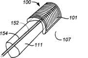
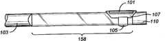
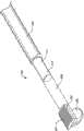
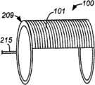
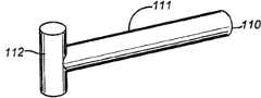
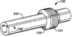
图5为具有完全圆周操作半径的烧蚀装置的实施方式的视图。Figure 5 is a view of an embodiment of an ablation device having a full circular operating radius.
图6为具有完全圆周操作半径的烧蚀装置的实施方式的视图,其中囊构件处于扩张配置。6 is a view of an embodiment of an ablation device having a full circumferential operating radius with the balloon member in an expanded configuration.
图7A至图7C示出了图5的装置的电极图形。7A to 7C show electrode patterns of the device of FIG. 5 .
图8A至图8D示出了能够用于具有完全圆周操作半径的烧蚀装置的实施方式、或者用于这里所描述的任何装置的实施方式的电极图形。8A-8D illustrate electrode patterns that can be used with an embodiment of an ablation device having a full circular operating radius, or with an embodiment of any of the devices described herein.
图9为具有部分圆周操作半径的本发明的烧蚀装置的视图。Figure 9 is a view of an ablation device of the present invention having a partial circumferential operating radius.
图10为图9的烧蚀装置实施方式的端视图。FIG. 10 is an end view of the embodiment of the ablation device of FIG. 9 .
图11为图9的装置处于扩张配置的端视图。Figure 11 is an end view of the device of Figure 9 in an expanded configuration.
图12、图13和图14为图9的装置处于替代的扩张配置的端视图。12, 13 and 14 are end views of the device of Fig. 9 in an alternative expanded configuration.
图15为本发明的烧蚀装置处于未扩张配置的视图。Figure 15 is a view of the ablation device of the present invention in an unexpanded configuration.
图16为本发明的烧蚀装置处于扩张配置的视图。Figure 16 is a view of the ablation device of the present invention in an expanded configuration.
图17和图18为装置处于扩张配置的端视图。17 and 18 are end views of the device in an expanded configuration.
图19A为示出偏转构件特征的本发明的烧蚀装置的视图。Figure 19A is a view of the ablation device of the present invention showing deflection member features.
图19B为示出替代的偏转构件的本发明的烧蚀装置的视图,其中该装置处于扩张配置。Figure 19B is a view of the ablation device of the present invention showing an alternative deflection member, with the device in an expanded configuration.
图20为图19B所示的装置的视图,其中偏转构件处于未扩张配置。Figure 20 is a view of the device shown in Figure 19B with the deflection member in an unexpanded configuration.
图21为装置处于未扩张配置的端视图。Figure 21 is an end view of the device in an unexpanded configuration.
图22为图21所示的装置处于扩张配置的端视图。Figure 22 is an end view of the device shown in Figure 21 in an expanded configuration.
图23为示出枢转烧蚀结构特征的本发明的烧蚀装置的视图。Figure 23 is a view of the ablation device of the present invention showing the pivotal ablation feature.
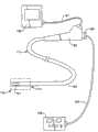
图24为与内窥镜系统结合的本发明的烧蚀装置的视图。Figure 24 is a view of the ablation device of the present invention integrated with an endoscopic system.
图25为通过部分胃肠道的壁的截面示意图。Figure 25 is a schematic cross-sectional view through the wall of a portion of the gastrointestinal tract.
图26为包括细长护套特征的本发明的烧蚀装置的视图。Figure 26 is a view of an ablation device of the present invention including an elongated sheath feature.
图27为其中细长护套特征透光的装置视图。Figure 27 is a view of the device in which the elongated sheath features are light transmitting.
图28为装置透光特征的放大图。Figure 28 is an enlarged view of the optically transparent features of the device.
图29为图27和28所示的装置的透光护套特征的截面图。29 is a cross-sectional view of the light transmissive sheath feature of the device shown in FIGS. 27 and 28. FIG.
图30为包括替代的透光护套特征和处于扩张配置的胀大构件特征的装置的视图。30 is a view of a device including an alternative light transmissive sheath feature and an inflatable member feature in an expanded configuration.
图31为定位在食道内的图30的烧蚀装置的视图。31 is a view of the ablation device of FIG. 30 positioned within the esophagus.
图32为包括狭缝护套特征的本发明的烧蚀装置的视图。Figure 32 is a view of an ablation device of the present invention including a slot sheath feature.
图33A为装置的狭缝护套特征的端视图,其中护套处于未扩张配置。Figure 33A is an end view of the slit sheath feature of the device with the sheath in an unexpanded configuration.
图33B为装置的狭缝护套特征和内窥镜的端视图,其中护套处于扩张配置。Figure 33B is an end view of the slit sheath feature of the device and the endoscope with the sheath in an expanded configuration.
图34A为定位在内窥镜内部工作通道内的装置的截面图,其中可胀大构件特征处于未扩张位置。34A is a cross-sectional view of the device positioned within the internal working channel of an endoscope with the expandable member feature in an unexpanded position.
图34B为图34A所示的装置的视图,其中可胀大构件特征处于扩张位置。Figure 34B is a view of the device shown in Figure 34A with the expandable member feature in an expanded position.
图35A为定位在内窥镜内部工作通道内的装置的截面图,其中可扩张构件特征处于未扩张位置。35A is a cross-sectional view of the device positioned within the internal working channel of an endoscope with the expandable member feature in an unexpanded position.
图35B为图35A所示的装置的视图,其中可扩张构件特征处于扩张位置。Figure 35B is a view of the device shown in Figure 35A with the expandable member feature in an expanded position.
图36A为定位在内窥镜内部工作通道内的装置的截面图,其中替代的可扩张构件特征处于未扩张位置。36A is a cross-sectional view of the device positioned within the internal working channel of an endoscope with an alternative expandable member feature in an unexpanded position.
图36B为图36A所示的装置的视图,其中可扩张构件特征处于扩张位置。Figure 36B is a view of the device shown in Figure 36A with the expandable member feature in an expanded position.
图37为包括替代的偏转构件的本发明的烧蚀装置的视图。Figure 37 is a view of an ablation device of the present invention including an alternative deflection member.
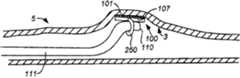
图38为包括在急性或慢性胃肠道出血部位定位在未偏转位置的替代的偏转构件的本发明的烧蚀装置的视图。38 is a view of an ablation device of the present invention including an alternative deflection member positioned in an undeflected position at a site of acute or chronic gastrointestinal bleeding.
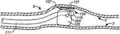
图39为图38所示的装置的视图,其中偏转构件处于偏转位置。Figure 39 is a view of the device shown in Figure 38 with the deflection member in a deflected position.
图40为示出内部联接机构特征的本发明的烧蚀装置的截面图。Figure 40 is a cross-sectional view of the ablation device of the present invention showing features of the internal coupling mechanism.
图41为示出替代的内部联接机构和卷起的护套特征的本发明的烧蚀装置的截面图。41 is a cross-sectional view of an ablation device of the present invention showing an alternative internal coupling mechanism and rolled sheath feature.
图42为定位在急性或慢性胃肠道出血部位的内腔中的本发明的烧蚀装置的截面图。42 is a cross-sectional view of an ablative device of the present invention positioned in the lumen of a site of acute or chronic gastrointestinal bleeding.
图43为示出转动特征的定位在食道内的本发明的烧蚀装置的视图。Figure 43 is a view of the ablation device of the present invention positioned within the esophagus showing the rotational feature.
图44为示出与处于扩张配置的胀大构件结合的转动特征的定位在食道内的本发明的烧蚀装置的视图。44 is a view of the ablation device of the present invention positioned within the esophagus showing the rotational feature in combination with the inflation member in the expanded configuration.
图45A至图45C为示出替代的转动特征的本发明的烧蚀装置的视图。45A-45C are views of the ablation device of the present invention showing alternative rotational features.
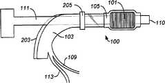
图46A为内窥镜的视图。Figure 46A is a view of an endoscope.
图46B为包括导管特征的本发明的烧蚀装置的视图。Figure 46B is a view of an ablation device of the present invention including catheter features.
图46C为装置的护套特征的视图。Figure 46C is a view of the sheath feature of the device.
图47为包括组装起来的图46A至图46C所示特征的本发明的烧蚀装置的视图。47 is a view of the ablation device of the present invention including the features shown in FIGS. 46A-46C assembled.
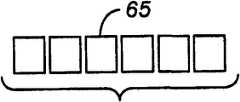
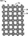
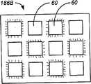
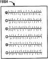
图48A至图48D示出了用于局部烧蚀的具有条纹图形的电极阵列以及能够由该图形形成在组织上的烧蚀图形。Figures 48A-48D illustrate an electrode array with a stripe pattern for localized ablation and the ablation pattern that can be formed on tissue from this pattern.
图49A和49B示出具有用于局部烧蚀的同心圆图形的电极阵列和能够由该图形形成在组织上的烧蚀图形。Figures 49A and 49B illustrate an electrode array with a pattern of concentric circles for localized ablation and the ablation pattern that can be formed on tissue from this pattern.
图50A和50B示出具有用于局部烧蚀的棋盘图形的电极阵列和能够由该图形形成在组织上的烧蚀图形。Figures 50A and 50B illustrate an electrode array with a checkerboard pattern for localized ablation and the ablation pattern that can be formed on tissue from this pattern.
图51A和51B示出以非局部方式操作的棋盘图形的电极阵列和能够由该操作图形形成在组织上的烧蚀图形。Figures 51A and 51B illustrate a checkerboard pattern of electrode arrays operating in a non-localized manner and the ablation patterns that can be formed on tissue from this operating pattern.
图52A和52B示出以局部方式操作的棋盘图形的电极阵列和能够由该操作图形形成在组织上的烧蚀图形。Figures 52A and 52B illustrate a checkerboard pattern of electrode arrays manipulated in a localized manner and the ablation patterns that can be formed on tissue from this manipulation pattern.
图53A和53B示出以非局部方式操作的交替正、负电极条纹图形的电极阵列和能够由该操作图形形成在组织上的烧蚀图形。Figures 53A and 53B illustrate an electrode array of alternating positive and negative electrode stripe patterns operating in a non-localized manner and the ablation patterns that can be formed on tissue from this operating pattern.
图54A和54B示出以局部方式操作的交替正、负电极条纹图形的电极阵列和能够由该操作图形形成在组织上的烧蚀图形。Figures 54A and 54B illustrate an electrode array of alternating positive and negative electrode stripe patterns operating in a localized manner and the ablation patterns that can be formed on tissue from this operating pattern.
图55示出在已经被烧蚀处理后,示意性给出的急性或慢性出血部位处胃肠道的放射状部分的目标区域的三维视图。Figure 55 shows a three-dimensional view schematically showing the target area of the radial portion of the gastrointestinal tract at the site of acute or chronic bleeding after it has been treated by ablation.
图56A和56B提供烧蚀装置的视图(与图38和39的装置类似),但是包括与图43所示的类似的在铰链结构或偏转机构上的烧蚀表面,铰链允许烧蚀表面在其纵向轴线和内窥镜的纵向轴线之间的自由枢转运动。图56A示出烧蚀表面与内窥镜平行地定向的装置。图56B示出烧蚀表面的纵向轴线关于内窥镜的纵向轴线成约直角地定位的装置。56A and 56B provide views of an ablation device (similar to the device of FIGS. 38 and 39 ), but including an ablation surface on a hinge structure or deflection mechanism similar to that shown in FIG. Free pivotal movement between the longitudinal axis and the longitudinal axis of the endoscope. Figure 56A shows the device with the ablation surface oriented parallel to the endoscope. Figure 56B shows a device with the longitudinal axis of the ablation surface positioned at approximately a right angle to the longitudinal axis of the endoscope.
图57A至图57D提供了具有位于卷绕在可扩张囊上的重叠的电极支撑物上的360度周向烧蚀表面的烧蚀装置的透视图,操作元件包括处于扩张状态的囊和电极支撑物。图57A示出支撑物被从囊拉开以示出支撑物的一部分和边缘粘附在囊上,且其另一部分和边缘不连接到囊。Figures 57A-57D provide perspective views of an ablation device having a 360 degree circumferential ablation surface on overlapping electrode supports wrapped around an expandable balloon, the operative element comprising the balloon and electrode support in an expanded state things. Figure 57A shows the strut being pulled away from the bladder to show that a portion and edge of the strut is adhered to the bladder and another portion and edge of the strut is not attached to the bladder.
图57B示出了装置的可操作元件,其中支撑物的非粘附部分以可展开的配置卷绕在囊上,且非粘附部分及其边缘绕着粘附部分重叠。Figure 57B shows the operable elements of the device with the non-adhered portion of the strut wrapped around the balloon in an expandable configuration, with the non-adhered portion and its edges overlapping around the adhered portion.
图57C示出了图57A和57B的装置具有可选的操作元件特征,一个以上弹性带绕在电极支撑物的周围。Figure 57C shows the device of Figures 57A and 57B with an optional operative element feature, one or more elastic bands wrapped around the electrode support.
图57D示出了处于折叠状态的图57C的装置,其中囊部分未胀大(或被缩小),当装置被放置入内腔中并且被定位于目标部位时以及当装置传递完烧蚀能量并且即将被从内腔中移除时,装置处于该状态。Figure 57D shows the device of Figure 57C in a folded state, with the balloon portion uninflated (or deflated), when the device is placed into the lumen and positioned at the target site and when the device has delivered ablation energy and is about to The device is in this state when removed from the lumen.
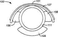
图58A-图58D示出了适于将烧蚀表面用于诸如气门或幽门的凹处或向内渐缩的目标部位的烧蚀表面的烧蚀装置的一种实施方式。该装置包括周向布置在可扩张构件的远侧部分上的烧蚀表面,可扩张构件安装在内窥镜的远端的周围。图58A示出该装置处于展开配置。58A-58D illustrate one embodiment of an ablation device adapted to apply an ablation surface to an ablation surface of a recess or inwardly tapered target site such as a stoma or pylorus. The device includes an ablation surface disposed circumferentially on a distal portion of an expandable member that fits about the distal end of the endoscope. Figure 58A shows the device in the deployed configuration.
图58B示出了图58A的装置的可扩张构件处于未扩张或塌缩状态,该状态适于将装置放置于目标的渐缩表面或适于将装置从烧蚀区域移除。Figure 58B shows the expandable member of the device of Figure 58A in an unexpanded or collapsed state suitable for placement of the device on a tapered surface of a target or for removal of the device from an ablated area.
图58C示出了图58A的装置能够被放入诸如幽门的渐缩的或凹入的目标部位。Figure 58C shows that the device of Figure 58A can be placed into a tapered or concave target site such as the pylorus.
图58D示出了处于替代的配置的图58A的装置,该装置的电极承载表面被反转为朝向近侧,并且能够被拉回至诸如下食道括约肌的渐缩的或凹入部位。Figure 58D shows the device of Figure 58A in an alternate configuration with the electrode bearing surface inverted proximally and capable of being pulled back into a tapered or concave site such as the lower esophageal sphincter.
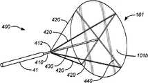
图59A和59B提供可以通过内窥镜的工作通道展开的烧蚀装置的视图,其中内窥镜能够提供基本正交或垂直于传递内窥镜的纵向轴线的大范围烧蚀表面。图59A示出装置处于完全展开配置。图59B示出装置处于可以被拉入内窥镜的工作通道中的收起配置。59A and 59B provide views of an ablation device that can be deployed through the working channel of an endoscope capable of providing an extensive ablation surface substantially normal or perpendicular to the longitudinal axis of the delivery endoscope. Figure 59A shows the device in a fully deployed configuration. Figure 59B shows the device in a stowed configuration where it can be drawn into the working channel of the endoscope.
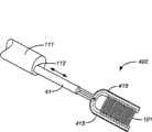
图60示出了可以通过内窥镜的工作通道展开的烧蚀装置的实施方式,内窥镜适于提供基本平行于传递内窥镜的纵向轴线的烧蚀表面。该装置包括具有两个平行可塌缩形状的记忆肋的烧蚀结构,烧蚀电极拉在两个肋之间,在处于展开状态时被拉的电极可以在肋之间的空间上是拉紧的。Figure 60 illustrates an embodiment of an ablation device deployable through a working channel of an endoscope adapted to provide an ablation surface substantially parallel to the longitudinal axis of the delivery endoscope. The device comprises an ablative structure with two parallel collapsible shaped memory ribs between which the ablative electrode is pulled, the pulled electrode can be taut in the space between the ribs when in the deployed state of.
图61A和61B示出了可以通过内窥镜的工作通道展开的烧蚀装置的实施方式,内窥镜适于提供基本平行于传递内窥镜的纵向轴线的烧蚀表面。该装置的烧蚀表面在其近端是渐缩的且基本是平的,但是具有可卷起来的横向曲线斜纹,使得其当被推出工作通道时展开,且当被拉回工作通道时绕其自身卷起。图61A示出了从工作通道向外伸出后该装置处于展开形式。图61B示出了装置在被展开前位于工作通道内或被拉回工作通道内后的外形。61A and 61B illustrate an embodiment of an ablation device deployable through the working channel of an endoscope adapted to provide an ablation surface substantially parallel to the longitudinal axis of the delivery endoscope. The ablative surface of the device is tapered and substantially flat at its proximal end, but has transverse curved slant that can be rolled up so that it unfurls when pushed out of the working channel and wraps around it when pulled back into the working channel. Roll up on itself. Figure 61A shows the device in the deployed configuration after being extended outwardly from the working channel. Figure 61B shows the appearance of the device before being deployed within the working channel or after being drawn back into the working channel.
图62示出了与图61类似的可以通过内窥镜的工作通道展开的烧蚀装置,区别在于通过在烧蚀表面近侧的柔性弯曲部分,内窥镜适于提供基本垂直于传递内窥镜的纵向轴线的烧蚀表面。装置的烧蚀表面在其近端是渐缩的且基本是平的,但是具有可卷起来的横向曲线斜纹,使得当被推出工作通道时展开,且当被拉回工作通道时绕其自身卷起。Figure 62 shows an ablation device similar to that of Figure 61 that can be deployed through the working channel of an endoscope, with the difference that, by means of a flexible bend proximal to the ablated surface, the endoscope is adapted to provide The ablated surface of the longitudinal axis of the mirror. The ablative surface of the device is tapered and substantially flat at its proximal end, but has transverse curvilinear slant that rolls up so as to unfold when pushed out of the working channel and to roll around itself when pulled back into the working channel rise.
图63示出了可以通过内窥镜的工作通道展开的烧蚀装置,内窥镜适于提供面向外侧周向的环形或螺旋形烧蚀表面。当从内窥镜的工作通道伸出时,环形或螺旋形部分展开,且当被拉回工作通道时卷成线形配置。Fig. 63 shows an ablation device deployable through the working channel of an endoscope adapted to provide an outer circumferentially facing annular or helical ablation surface. The annular or helical portion expands when extended from the working channel of the endoscope, and coils into a linear configuration when drawn back into the working channel.
图64提供了与图59至63所示的装置共用的烧蚀表面的线路层的透视和截面细节图。Figure 64 provides perspective and cross-sectional detail views of the wiring layers of the ablated surface common to the devices shown in Figures 59-63.
图65A和65B示出了具有包括液力清洁特征的部分周向烧蚀表面的烧蚀装置的实施方式。图65A示出了具有引导至烧蚀表面的液力管线的装置的侧视图。65A and 65B illustrate an embodiment of an ablation device having a partially circumferential ablation surface including hydraulic cleaning features. Figure 65A shows a side view of the device with hydraulic lines leading to the ablated surface.
图65B示出了烧蚀表面、液力入口和多个出口的更具体的透视图。Figure 65B shows a more detailed perspective view of the ablation surface, hydraulic inlet and multiple outlets.
具体实施方式Detailed ways
美国专利和美国专利申请中已经描述了利用完全圆周或部分圆周的烧灼结构(部分结合可扩张囊以将烧蚀结构靠着目标组织定位)的烧蚀技术的使用。利用部分圆周烧灼结构的装置和方法包括下述美国专利申请:11/286,257、11/286,444和11/275,244。利用完全圆周烧灼机构的装置和方法在美国专利6,551,310和7,150,745以及序列号为11/557,445、10/370,645、10/416,923、11/420,722、11/420,719、11/420,714、11/420,712、11/469,816(Shadduck)的美国专利申请和美国专利6,872,206中进行了描述。The use of ablation techniques utilizing fully or partially circumferential ablation structures, in part incorporating an expandable balloon to position the ablation structure against the target tissue, has been described in US patents and US patent applications. Devices and methods utilizing partial circumferential cautery configurations include the following US patent applications: Ser. Nos. 11/286,257, 11/286,444 and 11/275,244. Apparatus and methods utilizing a full circumferential cauterization mechanism in U.S. Patents 6,551,310 and 7,150,745 and Serial Nos. (Shadduck) and US Patent 6,872,206 are described.
这些装置和方法可以提供立即止血的效果,或者可以去除或改变倾向于将来出血的损伤,或者处理效果随着伤口愈合逐渐发展从而导致逐渐增加的止血效果。这样的处理效果可以在宽范围实现,并且通常本质上具有接合性、深度上具有一致性、可控制到需要的深度并且能够快速地传递。通过本发明的一些实施方式的烧蚀处理的宽范围方面是由于该装置的表面面积大,且能够反复地重新定位该装置以处理邻近和非邻近区域。因为下面的几种理由,血管的接合烧蚀被认为是一种有利的方法。首先,通过排除或减少目标部位的血液,减小了组织的热沉效应(吸热能力)从而形成更有效的止血效果。第二,通过在施加治疗之前由装置自身施加的压力将血管壁压迫或塌缩到一起,治疗能够导致血管壁烧结到一起从而阻止血液流动。由此,方法中诸如施加适合的压力的有利于接合凝结的步骤对于整个方法是有利的。由于烧蚀装置向目标组织或其中所包含的血管施加的压力,止血效果是接合性的。根据本发明的实施方式,一般由装置的可扩张构件当靠近目标部位时产生的或者由装置所安装或所通过的内窥镜的物理运动产生的压力,其等级在约1psig到约15psig的范围之间。更具体地,接合压力在约3psig到约7sig的范围之间。且更具体地,接合压力为约4psig。These devices and methods may provide an immediate hemostatic effect, or may remove or modify lesions predisposed to future bleeding, or the treatment effect may develop gradually as the wound heals resulting in an incremental hemostatic effect. Such treatment effects can be achieved over a wide range and are generally cohesive in nature, consistent in depth, controllable to desired depth and capable of rapid delivery. The broad aspect of ablative processing by some embodiments of the invention is due to the large surface area of the device and the ability to iteratively reposition the device to treat adjacent and non-adjacent areas. Junctional ablation of blood vessels is considered an advantageous approach for several reasons. First, by removing or reducing blood at the target site, the tissue's heat sink effect (capacity to absorb heat) is reduced resulting in more effective hemostasis. Second, the treatment can cause the vessel walls to sinter together preventing blood flow by compressing or collapsing the vessel walls together before the pressure applied by the device itself before the treatment is applied. Thus, steps in the method that facilitate joint coagulation, such as applying suitable pressure, are advantageous for the overall method. The hemostatic effect is zygotic due to the pressure exerted by the ablation device on the target tissue or blood vessels contained therein. According to an embodiment of the invention, the pressure typically generated by the expandable member of the device as it approaches the target site or by the physical movement of the endoscope on which the device is mounted or passed has a level in the range of about 1 psig to about 15 psig between. More specifically, the engagement pressure ranges from about 3 psig to about 7 sig. And more specifically, the bonding pressure is about 4 psig.
治疗参数可以使得全部或部分的目标损伤中实现一致的烧蚀等级。例如,对于表面损伤,需要的烧蚀深度可以是粘膜或部分粘膜。对于更深的损伤,烧蚀深度可以是更深的粘膜和全部或部分粘膜下层。烧蚀效果的深度控制和一致性是通过装置的特征和处理参数来实现的,包括电极图形、对目标损伤的压力、能量密度、功率密度和施加次数。The treatment parameters can be such that a consistent level of ablation is achieved in all or part of the target lesion. For example, for superficial lesions, the desired depth of ablation may be the mucosa or part of the mucosa. For deeper lesions, the depth of ablation can be deeper into the mucosa and all or part of the submucosa. Depth control and consistency of ablation effects are achieved through device features and treatment parameters, including electrode pattern, pressure on target damage, energy density, power density, and number of applications.
用于处理特定的出血部位或损伤的方法和装置的实施方式的选择,是基于发生出血的器官尺寸、内窥镜入口、出血部位和损伤的尺寸以及器官内膜的牵连程度。例如,在GAVE患者的胃窦中,出血损伤可能是窄且直线形(类似轮子放射的轮辐状)的,或者可能是融合且圆周形。在前一种情况下,可以优选使用焦点烧蚀和止血装置,例如具有部分圆周烧蚀表面的烧蚀导管或者这里所公开的其他焦点烧蚀装置。在后一种情况下,可以优选使用完全圆周烧蚀和止血装置。这两种类型的装置(即焦点或非圆周型以及圆周型装置)都可以被以多种方式安装在内窥镜上、穿过内窥镜或者沿着内窥镜的长度经过。此外,这些装置可以包括抵靠并压迫目标组织展开的基于囊或非基于囊的方法。The choice of method and device embodiment for treating a particular bleeding site or injury is based on the size of the organ in which the bleeding is occurring, the endoscope inlet, the size of the bleeding site and injury, and the degree of involvement of the organ lining. For example, in the antrum of a patient with GAVE, the hemorrhagic lesion may be narrow and rectilinear (like the radial spokes of a wheel) or may be fused and circumferential. In the former case, it may be preferable to use a focal ablation and hemostasis device, such as an ablation catheter with a partially circumferential ablation surface or other focal ablation devices disclosed herein. In the latter case, it may be preferable to use a full circumferential ablation and hemostasis device. Both types of devices (ie, focal or non-circumferential as well as peripheral devices) can be mounted on, through, or along the length of the endoscope in a variety of ways. Additionally, these devices may include balloon-based or non-balloon-based methods of deployment against and against target tissue.
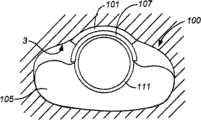
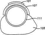
该方法以及执行该方法的装置的实施方式可以被作用于胃肠道中急性或慢性出血的部位。图1A和图1B提供了具有出血血管4的胃肠道的一部分的壁的截面示意图。图1A示出了血管(小动脉或小静脉)的一部分,带有主要位于固有层和上皮的分叉毛细血管。图1B示出了血管(小动脉或小静脉)的一部分,带有主要位于粘膜下层和固有层的分叉毛细血管。这些图的要点在于脆弱的出血血管可能位于胃肠道的特定的层中。在一些情况下,可以根据已知的特定症状的特征来了解所包括的组织学的层。在其他急性或慢性出血情况下,可以根据患者病历、活体检查或手术前或手术中的内窥镜观察来了解患者的具体信息,从而提供指示以优先地确定有问题的血管的特定的组织深度。在图1A所提供的实例中,适于提供深度控制烧蚀能量使得在上皮层和固有层发生烧蚀。在图1B所提供的实例中,适于提供深度控制烧蚀能量使得在粘膜下层、黏膜肌层和固有层发生烧蚀。Embodiments of the method and devices for performing the method may be applied to sites of acute or chronic bleeding in the gastrointestinal tract. 1A and 1B provide schematic cross-sectional views of the wall of a portion of the gastrointestinal tract with a bleeding
图2A至图2C提供了胃肠道中可以成为急性或慢性出血源(也是根据本发明的方法和装置的实施方式的止血烧蚀的目标)的特定的实例的症状。图2A示出了显示为位于上游动脉4a和下游静脉4v之间的血管团的动静脉畸形(AVM)4avm。图2B提供了毛细血管扩张的示意图,其中扩得非常大的毛细血管4c位于上游动脉4a和下游静脉4v之间。图2C提供了朝向患者的幽门9看时的胃的内窥镜向着远端的视图,其具有胃窦血管扩张(GAVE)的特征的大范围西瓜图案的胃损伤4wm。这些损伤4l既可以如内窥镜所观察地从内部看到,也可以在覆盖胃的皮肤上从外部看到。Figures 2A-2C provide specific examples of symptoms in the gastrointestinal tract that can be a source of acute or chronic bleeding that is also the target of hemostatic ablation according to embodiments of the methods and devices of the present invention. Figure 2A shows an arteriovenous malformation (AVM) 4avm shown as a vascular mass located between an
现在讨论这里所提供的治疗烧蚀方法中决定合适的烧蚀处理部位的方面(图3),以及在这种处理过程中将施加的烧蚀能量的量的方面,这些决定由医生对于特定的患者能够收集的所有的临床资料产生。在一些实施方式中,对急性或慢性胃肠道出血的部位进行初步内窥镜检查可能是合适的,从而可以勾画出特定患者的特征,以及评估患者消化道的大致尺寸。这些信息可以通过内窥镜方式直接视觉观察获得,或可选地使用粘膜层现场染色剂可以通过其他诊断方法完成,包括诸如内窥镜窄带成像的无创穿透成像方法,或者本领域已知的任何传统方法。在一个方面,部位评估包括确定部位的位置,包括其尺寸。在另一个方面,目标组织区域的评估包括如果有多于一个部位则确定多个部位,并进一步确定它们的位置和各自的尺寸。在又一个方面,目标部位评估可以包括确定或对急性或慢性胃肠道出血部位的病状或损伤或特定的特征进行分级,并特别地确定与待烧蚀目标区域重叠或靠近的任何具有临床意义或影响的区域。Discussing now the aspects of the therapeutic ablation method presented here that determine the appropriate site for ablative treatment (Fig. All clinical data generated by the patient can be collected. In some embodiments, initial endoscopic examination of sites of acute or chronic GI bleeding may be appropriate to allow patient-specific characterization and assessment of the approximate dimensions of the patient's digestive tract. This information can be obtained by direct visual observation by endoscopic means, or alternatively using mucosal layer situ stains can be accomplished by other diagnostic methods, including non-invasive penetrating imaging methods such as endoscopic narrow-band imaging, or as known in the art any traditional method. In one aspect, site assessment includes determining the location of the site, including its size. In another aspect, the assessment of the target tissue region includes identifying multiple sites, if more than one, and further determining their location and respective size. In yet another aspect, target site assessment can include identifying or grading pathology or injury or specific features at the site of acute or chronic GI bleeding, and specifically identifying any clinically significant disease that overlaps or is adjacent to the target area to be ablated. or affected area.
一旦确定了烧蚀的目标部位,可以使用这里所描述的具有创造性的烧蚀装置和相关联的方法来处理急性或慢性胃肠道出血部位的目标组织。烧蚀目标组织部位的状态的评估,尤其是通过视觉方法,也可以有利地作为烧蚀治疗方法(图3)的一部分来执行,例如与烧蚀紧密配合,或者紧邻施加烧蚀能量(例如辐射能量)之前,和/或紧跟其后。此外,可以在烧蚀处理之后的一些临床上适合的时间(例如数日、数周或数月后,或当烧蚀处理后临床上需要的任何时间)通过任何诊断或视觉方法对处理部位进行评估。如果任何后续评估显示出治疗结果不满意或烧蚀目标细胞的数量恢复,可能表示需要重复烧蚀治疗。Once the target site for ablation is determined, the inventive ablation devices and associated methods described herein can be used to treat target tissue at the site of acute or chronic gastrointestinal bleeding. Assessment of the status of the ablated target tissue site, especially by visual means, may also advantageously be performed as part of the ablation treatment method (Fig. 3), e.g. Energy) before, and/or immediately after. In addition, the treated site can be visualized by any diagnostic or visual method at some clinically appropriate time after the ablative treatment (e.g., days, weeks, or months later, or whenever clinically necessary after the ablative treatment). Evaluate. Any follow-up evaluation showing unsatisfactory treatment results or recovery of the number of ablated target cells may indicate the need for repeat ablation therapy.
现在讨论旨在对失败的旁路手术进行烧蚀校正的烧蚀装置,如这里具体讨论的,烧蚀装置具有与诸如电极的能量传递元件排列在一起的烧蚀结构。在一些实施方式中,根据治疗中所使用的烧蚀能量的类型,该装置可以被安装于或支承在允许烧蚀表面移动至目标部位位置的任何器械上。这些器械的形式和尺寸适于到达目标组织部位,并且可以包括适于该目的的简单的导管;插入器械的一些实施方式包括除了支撑作用之外还提供视觉能力的内窥镜。在该方法的一些实施方式中,提供视觉信息,与支撑器械分离的内窥镜可以参与到烧蚀操作中。Discussing now ablative devices intended for ablation correction of failed bypass procedures, as discussed in detail herein, ablative devices having ablative structures aligned with energy delivery elements such as electrodes. In some embodiments, depending on the type of ablative energy used in the treatment, the device may be mounted or supported on any instrument that allows the ablation surface to be moved to the location of the target site. These instruments are of a form and size suitable for reaching the target tissue site, and may include simple catheters suitable for this purpose; some embodiments of the insertion instrument include endoscopes that provide visual capabilities in addition to support. In some embodiments of the method, providing visual information, the endoscope detached from the supporting instrument may participate in the ablation procedure.
这种创造性装置的示例性的实施方式一般利用电极来传递射频能量,但是这种能量传递的类型是非限制性的,因为在本发明的实施方式中也包括使用其他形式的能量和其他形式的能量传递硬件。本发明的实施方式所提供的烧蚀能量可以包括例如由天线发射的微波能量、光电元件发射的光能、从加热的烧蚀结构表面以传导方式传递的或通过加热气体或液体直接传递至组织的热能、或者烧蚀结构表面的低温或低温冷却所提供的或通过冷的气体或喷出的液体或喷雾与组织直接接触所施加的能量热沉汲取、或者通过将冷的气体或液体与组织隔开的装置的壁的热的汲取。Exemplary embodiments of the inventive device generally utilize electrodes to deliver radio frequency energy, but the type of energy delivery is not limiting as the use of other forms of energy and other forms of energy are also included in embodiments of the invention Pass the hardware. Ablation energy provided by embodiments of the present invention may include, for example, microwave energy emitted by an antenna, light energy emitted by a photoelectric element, delivered conductively from the surface of a heated ablated structure, or delivered directly to tissue by heated gas or liquid The thermal energy provided by the thermal energy, or cryogenic or cryogenic cooling of the surface of the ablated structure, or the energy applied by the direct contact of the cold gas or sprayed liquid or spray with the tissue. Heat extraction from the wall of the partitioned device.
烧蚀装置的实施方式包括关于有待处理的烧蚀表面的圆周范围的变型,一些实施方式提供完全圆周的烧蚀表面而其他的提供不足完全圆周的表面,如上文所描述的。如图3所示,所提供的治疗方法中包括选择适合的装置的步骤。根据消化道壁上的一个或多个目标组织部位的性质、大小、位置和尺寸,这些以及其他的变型可以提供特定的优点。本发明的一种实施方式包括具有完全圆周(即围绕半径超过360度)的烧蚀表面使得管腔器官的完全放射状区域承受烧蚀。在该区域内,根据能量输出和烧蚀元件(如电极)的图形,可以针对各种角度实施烧蚀,但是在该烧蚀区域内具有基本的一致性。该实施方式可能特别地适合处理胃肠道急性或慢性出血部位内的分布广或扩散的部位。在该装置的其他的实施方式中,所发明的装置的烧蚀表面是部分圆周,使得其接合管腔器官的完全内周长或圆周的局部。管腔器官的内表面上被烧蚀的圆周的局部取决于被处理的管腔器官的尺寸和构造(半径、直径、或周长、或倾斜度)以及烧蚀表面的尺寸,如下文将更具体描述的。关于处理小而分散的目标部位,后一个实施方式所提供的更小或更分散的烧蚀表面可能是有利的。Embodiments of the ablation device include variations with respect to the extent of the circumference of the ablated surface to be treated, with some embodiments providing a fully circumferential ablation surface and others providing a less than fully circumferential surface, as described above. As shown in Figure 3, the provided treatment method includes the step of selecting an appropriate device. These and other variations may provide particular advantages depending on the nature, size, location and dimensions of the one or more target tissue sites on the wall of the alimentary canal. One embodiment of the invention includes an ablation surface having a complete circumference (ie, more than 360 degrees around a radius) such that a completely radial region of a luminal organ is subjected to ablation. Within this region, depending on the energy output and the pattern of the ablation elements (eg, electrodes), ablation can be performed at various angles, but with substantial uniformity within this ablation region. This embodiment may be particularly suitable for treating widespread or diffuse sites within acute or chronic bleeding sites of the gastrointestinal tract. In other embodiments of the device, the ablative surface of the inventive device is partial circumference such that it engages the full inner circumference of the luminal organ or a portion of the circumference. The locality of the ablated circumference on the inner surface of the luminal organ depends on the size and configuration (radius, diameter, or circumference, or inclination) of the luminal organ being treated and the size of the ablated surface, as will be discussed more below. specifically described. The smaller or more dispersed ablation surface provided by the latter embodiment may be advantageous with respect to treating small and dispersed target sites.
对围绕着360度周向阵列的烧蚀能量元件的周向子集的操作控制的类型与对电极阵列的子集图形的局部操作类似,如下文在题为“组织表面区域上的电极图形和烧蚀图形控制”的部分所描述的。在阵列的部分圆周操作中,阵列的特定弧受到激励以将能量传递至圆周的弧上。在阵列的局部图形操作中,将能量传递至目标区域的组织的一部分,而另一部分接收不足实现烧蚀的能量。在一些实施方式中可以将这些操作变化结合起来,也就是可以激励周向弧的图形子集。The type of operational control over a circumferential subset of ablative energy elements surrounding a 360-degree circumferential array is similar to the local manipulation of a subset pattern of an electrode array, as described below in the article entitled "Electrode Patterns and Ablation Over Tissue Surface Areas." Graphics Controls" section as described. In partial circular operation of the array, specific arcs of the array are energized to transfer energy to the arcs of the circumference. In a local pattern operation of the array, energy is delivered to a portion of the tissue of the target area while another portion receives insufficient energy to achieve ablation. In some embodiments these operational variations may be combined, ie a graphical subset of the circumferential arc may be excited.
图3和图4共同提供表示在急性或慢性胃肠道出血部位进行组织烧蚀的方法的实施方式的流程图。这些图代表了该装置的两个实施方式所传达的该方法实施方式的共同部分,一种具有360度周向烧蚀结构,而另一种具有包括小于360度弧的烧蚀结构。Figures 3 and 4 together provide a flow diagram representing an embodiment of a method of tissue ablation at a site of acute or chronic gastrointestinal bleeding. These figures represent the common parts of the embodiment of the method conveyed by two embodiments of the device, one having ablated
图3为示出了方法概况的流程图,该方法集中于患者评估和消化道内用于烧蚀处理的临床适合部位的确定。在另一个步骤,责任医生根据资料决定根据何种适合的实施方式来治疗患者,即,使用360度电极阵列的装置100A还是电极排列于在小于360度的弧内的装置100B。在选择使用装置100A的情况下,可以在360度圆周上操作电极或者操作电极阵列的径向子集之间进行另外的处理选择。在另一个步骤,考虑待传递的能量的量、能量密度和传递能量的持续时间,医生进一步考虑并决定烧蚀的治疗方案。这些考虑的对象包括待烧蚀的表面面积、待处理的组织深度、以及电极阵列的特征,例如是否为局部电极、以及需要哪种图形。不管选择怎样的装置,操作该方法的另一个预备步骤可以包括对消化道内的目标组织部位的进一步评估。部位评估可以包括提供离散的目标组织部位的数量、尺寸、精确位置和/或临床状态是否明显正常或异常的具体检查的任何视觉或诊断方法。该步骤被显示为位于选择器械之后,但也可以简单地与诊断一起进行,或者在诊断和基本确定目标组织位置之后的任一点。在任意情况下,评估步骤一般在烧蚀之前进行,如图4的流程图示出的方法的操作步骤中所概括的。在下述描述中,标记100可总体上用来表示烧蚀装置,不管其烧蚀表面101为完全圆周或部分圆周。Figure 3 is a flowchart showing an overview of the method focused on patient assessment and determination of a clinically appropriate site within the alimentary canal for ablative treatment. In another step, the responsible physician decides according to the data which is the appropriate embodiment to treat the patient, ie device 100A using a 360-degree electrode array or device 100B with electrodes arranged in an arc less than 360 degrees. Where the device 100A is chosen to be used, additional treatment options may be made between manipulating the electrodes on a 360 degree circumference or manipulating a radial subset of the electrode array. In another step, the physician further considers and decides on a treatment plan for ablation, taking into account the amount of energy to be delivered, the energy density, and the duration of energy delivery. These considerations include the surface area to be ablated, the depth of tissue to be treated, and the characteristics of the electrode array, such as whether it is a local electrode and what pattern is required. Regardless of the device chosen, another preliminary step in performing the method may include further evaluation of the target tissue site within the alimentary canal. Site assessment may include any visual or diagnostic method that provides specific inspection of the number, size, precise location, and/or clinical status of discrete target tissue sites whether they are apparently normal or abnormal. This step is shown following selection of the instrument, but could also be performed simply with diagnosis, or at any point after diagnosis and substantially determining the location of the target tissue. In any case, the evaluation step generally precedes the ablation, as outlined in the operational steps of the method shown in the flowchart of FIG. 4 . In the following description,
图4为示出了在急性或慢性胃肠道出血部位的目标部位被定位且做出了关于优选的烧蚀装置的选择之后的方法的流程图。该方法包括部位评估,该部位评估如上文所述地包括位置、阶段、部位数量的确定和尺寸的详细情况,并且使用背景技术中所提供的参考文献中的具体方法,和/或使用现有技术人员已知的任何进一步的方法。该方法继续进行器械的插入并移动烧蚀结构至待烧蚀的目标组织的位置。然后,可以执行更精细的烧蚀结构移动,这种移动在烧蚀结构和目标组织部位之间形成对治疗有效的接触。在选择360度的实施方式的装置100A的情况下,可以通过将电极阵列下的囊胀大来形成对治疗有效的接触。在选择的实施方式为100B的情况下,装置的电极表面跨越小于360度的弧,使烧蚀表面进入对治疗有效的接触的移动可以包括囊的胀大、偏转构件的胀大、和/或偏转构件的移动,后文将具体描述所有上述移动。4 is a flowchart illustrating the method after a target site of an acute or chronic gastrointestinal bleeding site has been located and a selection has been made regarding a preferred ablation device. The method includes a site assessment including details of location, stage, number of sites, and size as described above, and using specific methods in the references provided in the background, and/or using existing Any further methods known to the skilled person. The method continues with insertion of the instrument and movement of the ablation structure to the location of the target tissue to be ablated. Then, finer movement of the ablated structure can be performed, which creates a therapeutically effective contact between the ablated structure and the target tissue site. Where the 360 degree embodiment of device 100A is selected, therapeutically effective contact can be made by inflating the balloon under the electrode array. In the case of selected embodiment 100B, where the electrode surfaces of the device span an arc of less than 360 degrees, movement of the ablated surface into therapeutically effective contact may include inflation of the balloon, inflation of the deflection member, and/or The movement of the deflection member, all of the above-mentioned movements will be described in detail later.
在形成对治疗有效的接触之后,通过实施方式100A或100B中的任意一种,并通过执行任意的移动类型,下一个步骤包括从装置释放烧蚀能量。烧蚀能量释放的变型可以包括烧蚀单个部位,以及将装置移动至在评估步骤所确定的第二或随后部位。在烧蚀步骤之后,下一个步骤可以包括评估被处理的目标部位;可替代地,烧蚀结果的评估可以包括收集临床数据以及观察患者。在手术中使用内窥镜作为支撑烧蚀结构的器械或者作为单独的器械的情况下,在手术过程中当器械已经就位时,该评估可以在烧蚀之后立刻或很快进行。在该方法的其他实施方式中,被处理的部位可以在手术之后的任意临床适合时间被评估,例如下一天、或下一周、或数月之后。在这些评估的任意一种中显示烧蚀未完全完成、或显示目标细胞的不希望的再生的情况下,该方法适合于包括重复刚才描述并在图4中示意性地示出的步骤。After making a therapeutically effective contact, by either embodiment 100A or 100B, and by performing any type of movement, the next step involves releasing ablation energy from the device. Variations of ablative energy delivery may include ablating a single site and moving the device to a second or subsequent site determined in the evaluating step. Following the ablation step, the next step may include evaluating the treated target site; alternatively, evaluation of ablation results may include collecting clinical data and observing the patient. Where the endoscope is used intraoperatively as an instrument to support the ablated structure or as a separate instrument, this assessment can be performed immediately or shortly after ablation when the instrument is already in place during the procedure. In other embodiments of the method, the treated site may be assessed at any clinically appropriate time after surgery, such as the next day, or the next week, or months later. Where either of these assessments shows that ablation is not completely complete, or that unwanted regeneration of target cells is shown, the method is adapted to include repeating the steps just described and schematically shown in FIG. 4 .
360度周向烧蚀的装置和方法Apparatus and method for 360 degree circumferential ablation
根据本发明完成对急性或慢性胃肠道出血部位的血管组织进行烧蚀的方法,包括以能够完成对胃肠道中出血部位进行烧蚀的等级释放辐射能量。在本部分所描述的一般的实施方式中,辐射能量分配元件能够沿周向围绕360度进行构造。替代使用烧蚀结构发出射频能量,其他能量源可以同烧蚀结构一起使用,以实现组织烧蚀并且可以不需要电极。这些替代的能量源包括:紫外线、微波能量、超声能量、从加热流体媒介传递的热能、由加热元件传递的热能、诸如蒸汽的受热气体加热烧蚀结构或通过蒸汽-组织接触而直接加热组织、准直或非准直光能、烧蚀结构中或周围的冷却流体或气体传递或通过低温流体/气体-组织接触而直接冷却组织的低温能量。使用上述这些形式的烧蚀能量的系统和方法的实施方式包括使得结构、控制系统、功率供给系统、以及所有其它的辅助支撑系统和方法都适于被传递的烧蚀能量类型的修正。A method of accomplishing ablation of vascular tissue at a site of acute or chronic gastrointestinal bleeding in accordance with the present invention includes delivering radiant energy at a level capable of accomplishing ablation of the bleeding site in the gastrointestinal tract. In the general embodiment described in this section, the radiant energy distribution element can be configured circumferentially around 360 degrees. Instead of using the ablative structure to deliver radiofrequency energy, other energy sources can be used with the ablative structure to achieve tissue ablation and electrodes may not be required. These alternative energy sources include: ultraviolet light, microwave energy, ultrasonic energy, thermal energy delivered from a heated fluid medium, thermal energy delivered by a heating element, heated gas such as steam heating ablated structures or direct heating of tissue through steam-tissue contact, Cryogenic energy delivered by collimated or uncollimated light energy, cooling fluid or gas in or around the ablated structure, or directly cooling tissue through cryogenic fluid/gas-tissue contact. Embodiments of systems and methods using these forms of ablative energy described above include modifications to adapt structures, control systems, power supply systems, and all other auxiliary support systems and methods to the type of ablative energy being delivered.
在完全圆周烧蚀装置的一些实施方式中,柔性轴包括被电绝缘层围绕的线缆并且包括位于其远端的辐射能量分配元件。在本发明的一种形式中,围绕器械的远端的定位和扩张装置具有足够的尺寸在能量分配元件的前方以及能量分配元件的侧面接触和扩张其所处的胃肠道急性或慢性出血部位(例如胃、幽门、小肠、直肠或肛门)的壁。例如,器械的远端可以通过可扩张囊或胀大构件被支撑在距急性或慢性出血部位的胃肠道壁受控的距离,使得在烧蚀结构和目标部位之间形成对治疗有效的接触,以当通过电极施加能量时允许调节以及控制传递至内腔中目标组织的能量的量。囊优选地与远端元件隔开的地方与柔性轴结合。In some embodiments of the full circumferential ablation device, the flexible shaft includes a cable surrounded by an electrical insulation layer and includes a radiant energy distributing element at its distal end. In one form of the invention, the positioning and dilating means around the distal end of the device are of sufficient size to contact and dilate the site of acute or chronic bleeding in the GI tract in front of the energy distributing element and laterally of the energy distributing element. (such as the wall of the stomach, pylorus, small intestine, rectum or anus). For example, the distal end of the device may be supported at a controlled distance from the wall of the gastrointestinal tract at the site of acute or chronic bleeding by an expandable balloon or inflatable member such that therapeutically effective contact is established between the ablated structure and the target site , to allow adjustment and control of the amount of energy delivered to the target tissue in the lumen when energy is applied through the electrodes. The capsule is preferably coupled to a flexible shaft where it is spaced from the distal element.
完全圆周烧蚀结构的一些实施方式包括可扩大或扩张的囊构件作为传递烧蚀能量的媒介。该实施方式的一个特征包括用于将能量从本发明的远端部分传递至包括囊构件的薄膜的装置。例如,美国专利5,713,942中示出了可能合适的一种能量分配的类型,该专利其整体通过引用包含于此,其中可扩张的囊联接到提供具有希望的特性的射频功率的功率源以选择性地将目标组织加热至希望的温度。本发明的实施方式的囊可以由导电弹性体构成,例如聚合体、弹性体和导电微粒的复合物,或者可以包括非延展性的囊状物,其在完全扩张形式下的形状和尺寸能够以适合的方式延伸至需要接触的组织。在另一种实施方式中,导电构件可以由导电弹性体构成,其中诸如铜的导电材料被沉积在表面上且在该材料中蚀刻出电极图形,然后将导电构件连接到囊构件的外表面。在一种实施方式中,导电构件,例如囊构件,其所具有的构造在形状上是可扩张的以适应急性或慢性出血部位处人体胃肠道内腔的扩张(非塌缩)的尺寸。此外,这种导电构件可以包括排列在烧蚀结构101上的多个电极段,烧蚀结构101具有与每个电极段相关联的一个或多个热敏电阻元件,通过热敏电阻元件可以监控并通过反馈控制多个段中的每段的温度。在另一种实施方式中,导电构件可以具有允许微波能量传递至烧蚀部位的装置。在又一种实施方式中,可扩大或扩张的囊构件可以具有用于运送或传递位于构件的一个或多个部分内的受热流体的装置,使得受热流体的热能可以被用作烧蚀能量源。Some embodiments of fully circumferentially ablative structures include an expandable or expandable balloon member as a medium for delivering ablative energy. A feature of this embodiment includes means for transferring energy from the distal portion of the present invention to the membrane comprising the balloon member. One type of energy distribution that may be suitable is shown, for example, in US Pat. efficiently heats the target tissue to the desired temperature. Bladders of embodiments of the present invention may be constructed of conductive elastomers, such as composites of polymers, elastomers, and conductive particles, or may include non-extensible bladders that, in their fully expanded form, are shaped and sized to Appropriate means extend to the tissue in need of contact. In another embodiment, the conductive member may be constructed of a conductive elastomer, where a conductive material such as copper is deposited on the surface and an electrode pattern is etched into the material, then the conductive member is attached to the outer surface of the bladder member. In one embodiment, a conductive member, such as a balloon member, has a configuration that is expandable in shape to accommodate the expanded (non-collapsed) dimensions of the lumen of the human gastrointestinal tract at the site of acute or chronic bleeding. In addition, such conductive members may include a plurality of electrode segments arranged on an
完全周向烧蚀装置的一些实施方式包括可转动和导向的控制装置、用于准确地感测烧灼深度的装置、以及诸如远侧能量分配头的适合的替代的实施方式,使得在不希望将导电元件放入形成可扩张囊构件的薄膜内的情况下在保持能量释放装置位于可扩张囊构件的体积内的同时仍能够使用囊构件进行放置和定位控制。Some embodiments of a fully circumferential ablation device include rotatable and steerable controls, means for accurately sensing the depth of ablation, and suitable alternate embodiments such as a distal energy dispensing head such that the Placement of the conductive elements within the membrane forming the expandable balloon member maintains the energy release device within the volume of the expandable balloon member while still enabling placement and positional control using the balloon member.
本发明的实施方式包括将诸如完全圆周烧蚀装置的烧蚀装置用于处理胃肠道中急性或慢性出血的部位的方法。在确定急性或慢性出血部位的胃肠道壁的一个或多个部分具有被作为完全或部分烧蚀目标的组织之后,以根据该装置将被使用的实施方式所适合的方式为患者准备进行手术。然后,在一种实施方式中,医生通过内窥镜入口和控制将所示出并在这里讨论的烧蚀装置插入患者。当合理定位并视觉确认烧蚀部位位于胃肠道急性或慢性出血部位时,对装置的部分进行进一步定位。在烧蚀导管构件上的适合的象限或部分/段的选择和激励是由内科医生执行的,包括根据希望的烧灼深度设定适合的功率。由于需要在患者消化道内急性或慢性出血部位的不同位置和/或不同深度进行烧蚀,可能需要额外的设定。烧蚀之后,在将装置从急性或慢性消化道出血部位中移除时和移除后对患者完成本领域已知的适合的后续步骤。Embodiments of the invention include methods of using an ablation device, such as a full circumference ablation device, for treating a site of acute or chronic bleeding in the gastrointestinal tract. After determining that one or more portions of the gastrointestinal tract wall at the site of acute or chronic bleeding have tissue targeted for complete or partial ablation, the patient is prepared for surgery in a manner appropriate to the embodiment in which the device is to be used . Then, in one embodiment, the physician inserts the ablative device shown and discussed herein into the patient through the endoscope port and controls. When reasonably located and visually confirmed that the ablated site is in the site of an acute or chronic gastrointestinal bleeding, proceed to further positioning of the portion of the device. Selection and activation of the appropriate quadrant or portion/segment on the ablation catheter member is performed by the physician, including setting the appropriate power according to the desired depth of ablation. Additional settings may be required due to the need to ablate at different locations and/or depths within the patient's GI tract for acute or chronic bleeding. Following ablation, appropriate subsequent steps known in the art are performed on the patient at the time of and after removal of the device from the site of acute or chronic GI bleeding.
在本发明的又一种方法中,医生可以首先确定需要烧蚀的急性或慢性消化道出血部位部分的长度,并且然后可以从本发明的多个烧蚀导管中选择一个,每个烧蚀导管都具有与囊构件相关联的不同长度的电极构件。例如,如果医生确定需要烧蚀的急性或慢性消化道出血表面部位为1厘米,在该烧蚀中可以选择使用1厘米的电极构件的烧蚀导管。与囊构件相关联的电极构件的长度可以变化,例如从1厘米到10厘米。In yet another method of the present invention, the doctor may first determine the length of the portion of the acute or chronic gastrointestinal bleeding site that needs to be ablated, and then may select one of a plurality of ablation catheters of the present invention, each ablation catheter Both have electrode members of different lengths associated with the balloon member. For example, if a physician determines that the acute or chronic GI bleeding surface site to be ablated is 1 cm, an ablation catheter using a 1 cm electrode member may be selected for this ablation. The length of the electrode member associated with the balloon member may vary, for example from 1 centimeter to 10 centimeters.
在又一种实施方式中,可以提供多个烧蚀导管,其中辐射能量分配元件与囊构件相关联,且当扩张时囊构件的直径可以从12mm到40mm变化。在该方法中,医生将选择扩张时的直径能导致急性或慢性胃肠道出血部位伸展且粘膜层变薄从而减小或阻止烧蚀部位的血流的烧蚀导管。一般认为通过减小烧蚀区域的血流,辐射能量产生的热量更不容易被传递到目标组织的其他区域从而使能量集中于烧蚀部位。In yet another embodiment, a plurality of ablation catheters may be provided, wherein the radiant energy distributing element is associated with a balloon member, and the diameter of the balloon member may vary from 12mm to 40mm when expanded. In this approach, the physician will select an ablating catheter that, when dilated, has a diameter that causes stretching of the site of acute or chronic GI bleeding and thinning of the mucosal layer thereby reducing or preventing blood flow to the ablated site. It is generally believed that by reducing the blood flow in the ablated area, the heat generated by the radiant energy is less likely to be transferred to other areas of the target tissue, thereby focusing the energy on the ablated site.
医生可以用来确定关于特定的患者使用的烧蚀导管的适合的直径的方法是首先将高度柔顺的囊连接到压力传感机构。可以将囊插入急性或慢性胃肠道出血部位内的管腔器官中,将其定位在希望烧蚀的部位,并将其胀大直至达到适合的压力读数。可以确定该胀大囊的直径,并选择具有能够扩张到该直径的囊构件的本发明的烧蚀装置来进行处理。在本发明的方法中,希望充分地扩张诸如囊的可扩张的导电构件以封闭粘膜下层的血管,包括动脉、毛细血管或静脉。因此,用于该目的而作用的压力应当比这些血管产生的压力要大。A method that physicians can use to determine the appropriate diameter of an ablation catheter to use with a particular patient is to first attach a highly compliant balloon to a pressure sensing mechanism. A balloon can be inserted into the luminal organ within the site of acute or chronic GI bleeding, positioned at the site desired to be ablated, and inflated until an appropriate pressure reading is achieved. The diameter of the inflated balloon can be determined and an ablation device of the present invention having a balloon member capable of expanding to that diameter can be selected for treatment. In the methods of the present invention, it is desirable to inflate the expandable conductive member, such as a balloon, sufficiently to occlude submucosa vessels, including arteries, capillaries or veins. Therefore, the pressure applied for this purpose should be higher than the pressure generated by these vessels.
在该方法的其它实施方式中,使用电子装置来测量已经执行过缩胃手术的胃肠特征的腔目标区域,从而使得能量可针对目标组织的表面面积被适当地规范化。该方法的这些方面在Wallace等人于2008年6月20日所提交的名称为“Electrical means to normalizeablational energy transmission to a luminal tissue surface of varyingsize”且序列号为12/143,404的美国专利申请中进行了具体描述,该专利申请整体通过引用包含于此。In other embodiments of the method, an electronic device is used to measure the luminal target area of a gastrointestinal feature on which a gastric reduction procedure has been performed so that the energy can be properly normalized for the surface area of the target tissue. These aspects of the method are described in U.S. Patent Application Serial No. 12/143,404, filed June 20, 2008, by Wallace et al., entitled "Electrical means to normalizeablational energy transmission to a luminal tissue surface of varying size" For a detailed description, this patent application is hereby incorporated by reference in its entirety.
除了图6所示的具有能够通过可扩张构件压迫目标区域以实现治疗接触的完全圆周烧蚀表面的烧蚀装置的代表性的实施方式之外,图57A至57D和图58A至图58B中提供了其他代表性的实施方式。Wallace等人于2008年6月20日所提交的名称为“Electrical meansto normalize ablational energy transmission to a luminal tissue surfaceof varying size”且序列号为12/143,404的美国专利申请中具体描述了图57A至图57D中所示出的实施方式,该专利申请整体通过引用包含于此。该申请具体描述了具有360度烧蚀表面的装置的实施方式,并在本申请的图57A至图57D中示出了该实施方式。在烧蚀处理的准备过程中也可以使用压力传感装置来测量内腔的尺寸,如序列号为11/244,385并被公开为US 2006/0095032的美国专利申请中所描述的。In addition to the representative embodiment of an ablative device having a fully circumferential ablative surface capable of compressing a target area by an expandable member to achieve therapeutic access as shown in FIG. Other representative embodiments are described. Figures 57A to 57D are specifically described in U.S. Patent Application Serial No. 12/143,404, filed June 20, 2008 by Wallace et al., entitled "Electrical means to normalize ablational energy transmission to a luminal tissue surface of varying size" The embodiment shown in the patent application is hereby incorporated by reference in its entirety. This application specifically describes an embodiment of a device having a 360 degree ablated surface and is shown in Figures 57A-57D of this application. A pressure sensing device may also be used to measure lumen dimensions in preparation for the ablation process, as described in US Patent Application Serial No. 11/244,385 and published as US 2006/0095032.
这里将简略地讨论Wallace等人的序列号为12/143,404的美国专利申请中所公开的装置的实施方式,以提供包括360度烧蚀表面的实施方式,该烧蚀表面布置在重叠的支撑物上,支撑物随着包含在支撑物周界内的囊而扩张。虽然该装置的周界整体地随着囊而扩张,但烧蚀表面本身是不可伸展的,并且保持其电极密度。图57A至图57D提供了烧蚀装置100的透视图,烧蚀装置100具有卷绕在可扩张的囊105上的重叠的电极支撑物360。诸如射频电极的烧蚀能量传递元件101的阵列布置在电极支撑物的外表面上。操作元件安装在烧蚀导管的远端,其中,能够看到轴41的远侧部分,且囊105围绕着烧蚀导管设置。图57A示出了电极支撑物360被从囊105拉开以示出支撑物的一部分和内边缘360粘附在囊上,其另一部分和其外边缘364不连接到囊。图57B示出了电极支撑物360的非粘附部分以可展开的配置卷绕在囊105上,且非粘附部分及其边缘绕着粘附部分重叠。图57C示出了装置100A的可选的特征,一个以上的弹性带380缠绕在电极支撑物360上。在一些实施方式中,弹性带380材料为导电弹性体,如后文将更具体描述的,并且能够被包含在尺寸感测电路中以提供关于操作元件扩张程度的信息。图57D示出了处于塌缩状态的图57C的装置,其中囊部分105未胀大(或被缩小),当装置被放置入内腔中并且被定位于目标部位时以及当装置传递完烧蚀能量并且即将被从内腔中移除时,装置处于该状态。Embodiments of the device disclosed in Wallace et al., U.S. Patent Application Serial No. 12/143,404 will be briefly discussed herein to provide embodiments that include 360-degree ablation surfaces disposed on overlapping supports , the strut expands with the capsule contained within the strut perimeter. While the perimeter of the device expands with the balloon as a whole, the ablated surface itself is inextensible and maintains its electrode density. 57A-57D provide perspective views of an
图58A至图58B中提供了具有完全圆周烧蚀表面的烧蚀装置的另一种实施方式。该特定的装置实施方式400适于将烧蚀表面101用于凹处或向内渐缩的目标部位,诸如胃窦的远侧部分,或进入幽门附近(此为西瓜胃典型的血管损伤部位)。该装置包括周向布置在可扩张构件105的远侧部分上的烧蚀表面,可扩张构件安装在内窥镜111的轴的远端110的周围。图58A示出该装置处于展开配置。图58B示出了该装置及可扩张构件处于未扩张或塌缩状态,该状态适于将装置放置于目标的渐缩表面或适于将装置从烧蚀部位移除。图58C示出了图58A的装置能够被放入诸如幽门9的渐缩的或凹处目标部位。图58D示出了处于替代的配置的图58A的装置,该装置的电极承载表面被反转为朝向近侧,并且能够被拉回至诸如下食道括约肌10的渐缩的或凹处部位。Another embodiment of an ablation device with a fully circumferential ablation surface is provided in FIGS. 58A-58B . This
电极图形和在组织表面区域上控制烧蚀图形Electrode patterns and controlled ablation patterns on tissue surface areas
现在将主要针对烧蚀结构上的电极图形来描述烧蚀装置和方法的实施方式的一些方面。图5至图7示意性地示出了所使用的装置。如图6所示,具有完全周向烧蚀表面的装置100的细长的柔性轴41连接到多管脚电连接器94,电连接器94连接到动力源并且包括阳型鲁尔连接器96以连接到能够用于扩张可扩张构件的流体源。细长的柔性轴具有围绕其周面的电极98。图5和图6中示出的装置的可扩张构件进一步地包括三种不同的电极图形,这些图形在图7A至图7C中更具体地示出。一般地,本发明的装置仅使用一种电极图形,但是也可以包括多于一种电极图形。在图5所示出的装置中,细长的柔性轴41包括在轴的一端间隔约2mm的6个双极环62(第一电极图形),邻近双极环的是间隔1mm的6个单极带或矩形65(第二电极图形),且另一种双极轴向交插电极68(第三电极图形)定位在轴的另一端。在该装置中,最后一个单极带与双极轴向电极之间定位有空隔70。使用涂有铜的约1mil(0.001″)的聚酰亚胺平板来准备该研究中使用的导管。然后将希望的电极图形蚀刻在铜上。Aspects of embodiments of ablation apparatus and methods will now be described primarily with respect to ablation of electrode patterns on structures. Figures 5 to 7 schematically illustrate the apparatus used. As shown in FIG. 6 , the elongated
图8A至图8D中分别示出了替代的电极图形80、84、88和92。图形80为间距为约0.3mm的双极轴向交插指状电极的图形。图形84包括具有0.3mm间隔的单极带。图形88为间距为约0.25mm的波形电极图形的电极。图形92包括具有约0.3mm间隔的双极环。在该情况下电极连接到直径为约18mm的囊72的外表面。通过将图5所示的电线74连接到电极从而将其连接到动力源,该装置可以适于使用无线电频率。
上述电极阵列布置是在具有完全360度烧蚀表面的烧蚀结构情况下描述的,但是这些图形及其变型也可以适用于结构上在小于完全圆周的表面上提供能量传递的烧蚀结构,例如在小于360度的周向的任意部分上烧蚀,或者例如在约90度或约180度半径上烧蚀。The electrode array arrangements described above are described in the context of ablation structures with a full 360 degree ablation surface, but these figures and variations thereof can also be applied to ablation structures that structurally provide energy transfer over surfaces less than a full circumference, such as Ablate over any portion of the circumference that is less than 360 degrees, or, for example, on a radius of about 90 degrees or about 180 degrees.
这里提供的烧蚀系统的实施方式其一般特征是电极图形在烧蚀支撑结构表面上基本是平坦的并且不穿透其所烧蚀的表面。电极图形构成连绵的处理区域,该处理区域包括管腔器官的一些基本放射状方面;该区域与电纤维、纤维喷雾或单根导线所留下的烧蚀图形不同。在本发明的一些实施方式中,放射状部分可以是完全周向的,被本发明的实施方式烧蚀的管腔器官的放射状部分是以下参数的函数:(1)器官的周长,其对于胃的情况可以相对较大而对于小肠或肛门区域的情况较小,和(2)电极图形的尺寸。因此,在高限,如上所述,如在胃中的处理区域的情况下,处理范围的径向范围可以大到360度,小到约5至10度。Embodiments of the ablation system provided herein are generally characterized in that the electrode pattern is substantially flat on the surface of the ablated support structure and does not penetrate the surface it ablates. The electrode pattern constitutes a contiguous treatment area that includes some essentially radial aspects of the luminal organ; this area is distinct from the ablation pattern left by electrical fibers, fiber sprays, or single wires. In some embodiments of the invention, the radial portion may be completely circumferential, the radial portion of a luminal organ ablated by an embodiment of the invention is a function of: (1) the circumference of the organ, which is relative to the gastric The case of can be relatively large and the case of the small intestine or anal region smaller, and (2) the size of the electrode pattern. Thus, at the high end, as described above, as in the case of the treated region in the stomach, the radial extent of the treatment field can be as large as 360 degrees and as small as about 5 to 10 degrees.
所提供的烧蚀能量传递系统和方法的实施方式,其特征还在于对目标组织是非穿透性的。烧蚀射频能量是如本申请别的地方所描述的当平的电极图形与处理区域的组织表面进行治疗接触时由电极图形传递的;且能量被从该表面接触点直接向内以到达组织层下方。Embodiments of the provided ablative energy delivery systems and methods are also characterized as being non-penetrating to target tissue. Ablation RF energy is delivered by the flat electrode pattern as it makes therapeutic contact with the tissue surface of the treatment area as described elsewhere in this application; and the energy is directed inward from the surface contact point to reach the tissue layers below.
所提供的烧蚀能量传递系统和方法的实施方式的进一步的特征在于其电极图形能够实现部分或局部烧蚀,从而仅一部分组织表面接收足够的射频能量以实现烧蚀,而另一部分接收不足以实现烧蚀的能量。该系统和方法能够进一步控制射频能量从组织表面向内部的传递使得能够控制足以烧蚀的能量被传递到的组织层的深度。Embodiments of the provided ablative energy delivery systems and methods are further characterized by electrode patterns that enable partial or localized ablation such that only a portion of the tissue surface receives sufficient RF energy to achieve ablation, while another portion receives insufficient radiofrequency energy. Energy to achieve ablation. The systems and methods further enable control of the delivery of radiofrequency energy from the surface of the tissue inwardly such that the depth of the tissue layer to which energy sufficient to ablate is delivered can be controlled.
控制被烧蚀的局部组织表面目标区域,包括将组织的一些局部至少烧蚀至一定程度,并且目标部位内的表面的一些局部产生自基本没有烧蚀的处理。控制被烧蚀和不被烧蚀的表面的比例的能力能为该处理提供明显的好处。根据本发明的实施方式,该烧蚀处理可以针对烧蚀血管组织,且对周围组织具有最小的影响或者可恢复的或暂时的影响。因此希望获得良好控制和调节的烧蚀,其能够在基本不损伤器官或器官的特定层的同时提供不同的烧蚀效果的程度。换句话说,为了目标血管组织所在的器官的健康或是为了个体整体的健康,一般可能希望烧蚀后在周围和介入组织中保留一定程度的正常功能。Controlling the ablated localized tissue surface target area includes ablating at least some localized portion of the tissue and some localized portion of the surface within the target site resulting from the treatment with substantially no ablation. The ability to control the proportion of ablated and non-ablated surfaces can provide significant benefits to the process. According to embodiments of the present invention, the ablative treatment may be directed at ablating vascular tissue with minimal or reversible or temporary impact on surrounding tissue. It is therefore desirable to have a well-controlled and regulated ablation capable of providing varying degrees of ablative effect while substantially not damaging the organ or specific layers of the organ. In other words, for the health of the organ in which the target vascular tissue is located, or for the overall health of the individual, it may generally be desirable to preserve some degree of normal function in the surrounding and intervening tissue after ablation.
关于包括细胞(包括血管细胞)的局部烧蚀的方法在目标区域内对血管组织的效果,在一定程度上局部烧蚀的功能可能与完全烧蚀同样有效。血管细胞,特别是形成血管的内皮细胞,以树状的方式生长。一般认为单独的血管系统不与单独的血管系统的其他部分邻接。因此,经过局部烧蚀过程存留下来但是与上游和下游连接分离的血管被孤立并且会被生物体再吸收。由此,通过前述考虑,可以理解目标区域特别是血管目标区域内的组织的局部烧蚀能够有效地烧蚀急性或慢性出血血管,并且能有利地使目标区域内的组织以良好的健康状态自由生长。由此该方法的实施方式包括控制射频能量在目标区域内的表面上和进入组织的深度的传递,并由将足以实现烧蚀的射频能量传递至组织目标区域的一部分并且将不足以实现烧蚀的射频能量传递至表面的另一部分。With regard to the effect of methods involving localized ablation of cells, including vascular cells, on vascular tissue within the target area, the function of localized ablation may to some extent be as effective as complete ablation. Vascular cells, particularly the endothelial cells that form blood vessels, grow in a tree-like fashion. An individual vasculature is generally considered not to be contiguous with other parts of the individual vasculature. Thus, blood vessels that survive the local ablation process but are separated from upstream and downstream connections are isolated and will be resorbed by the organism. Thus, through the aforementioned considerations, it can be understood that the localized ablation of tissue in the target area, especially the blood vessel target area, can effectively ablate acute or chronic bleeding blood vessels, and can advantageously free the tissue in the target area in good health. grow. Embodiments of the method thus include controlling the delivery of radiofrequency energy on the surface and depth into the tissue within the target region, and by delivering enough radiofrequency energy to a portion of the tissue target region and insufficient to achieve ablation The RF energy is transferred to another part of the surface.
进一步地以示例性的方式说明本发明所希望并且提供的结果,烧蚀目标区域所在的器官可以被理解为目标区域的非血管组织中细胞的总体,这些细胞能够根据其健康程度当在较差的状况下其功能能力处于某个低的阈值例如为20%,而在最佳状况下为100%。这里所提供的烧蚀处理的目标,在该示例中同样不会是使所有细胞都功能障碍并且在50%的能力下运行。处理的目的可以是使细胞总数中的一部分在烧蚀处理后保持全部的功能并以约100%的能力运行,而一些剩余的部分以较低能力的范围运行。To further illustrate the expected and provided results of the present invention in an exemplary manner, the organ where the ablation target area is located can be understood as the totality of cells in the non-vascular tissue of the target area, and these cells can be treated according to their health. Its functional capability is at a certain low threshold such as 20% under optimal conditions and 100% under optimal conditions. The goal of the ablative process presented here, again in this example, would not be to have all cells dysfunctional and operate at 50% capacity. The goal of the treatment may be to have a fraction of the cell population remain fully functional and operate at about 100% capacity after the ablative treatment, while some remaining fraction operate at a lower capacity range.
根据本发明的实施方式,控制被烧蚀的组织表面目标区域的局部具有多种示例性的方法,包括例如(1)电极图形的物理布置的间隔为以相对不密集的电极图形,以及(2)以类似布告栏的方法对相对密集的电极图形进行局部操作。一般来说,通过电极图形的物理配置形成局部烧蚀包括配置电极图形使得一些电极之间的间距足够近以允许在电极之间传递给定的足以烧蚀组织的能量等级,而其他电极之间的间距不足够近从而不允许传递足以烧蚀的该等级能量。下文描述了并在图48至图55中示出了使用该方法以形成局部烧蚀的示例性的电极图形的实施方式。通过激励电极的子集来形成烧蚀图形表示与上述类似的一种发明的系统和方法的操作,其中具有完全圆周电极图形的烧蚀结构能够以使得仅有径向局部的电极被操作的方式来操作。According to the embodiment of the present invention, there are various exemplary methods for controlling the locality of the target region on the surface of the tissue to be ablated, including (1) the physical arrangement of the electrode patterns is relatively less densely spaced electrode patterns, and (2) ) performs local operations on relatively dense electrode patterns in a bulletin board-like manner. In general, creating localized ablation through the physical arrangement of electrode patterns includes configuring electrode patterns such that some electrodes are spaced close enough to allow a given energy level sufficient to ablate tissue to be delivered between the electrodes, while other electrodes are spaced close enough to each other. The spacing is not close enough to allow delivery of this level of energy sufficient to ablate. Embodiments of exemplary electrode patterns using this method to form localized ablation are described below and shown in FIGS. 48-55 . Forming an ablation pattern by energizing a subset of electrodes represents operation of an inventive system and method similar to that described above, wherein an ablation structure with a fully circumferential electrode pattern can be operated in such a manner that only radially localized electrodes are manipulated to operate.
本发明的烧蚀系统包括具有多个电极的电极图形以及支撑该电极图形的纵向支撑构件,如这里的多种实施方式所描述的。发生器将能量传递给电极,而发生器的操作是通过与发生器通信的计算机控制器来控制的,该计算机控制器控制电极的操作参数。计算机控制器具有引导发生器将能量传递给所有电极或者传递给电极的子集的能力。控制器还具有控制能量传递的时序,使得电极可以被同时激励,或者按电极的子集、非同时激励。此外,如别处描述的那样,电极可以以单极模式、双极模式或复用模式来操作。这些多种操作方法,特别是通过激励图形中的电极的子集的方法,允许形成当图形与目标表面治疗接触时能够烧蚀目标区域内的部分组织且使目标区域内的部分组织不被烧蚀的图形。The ablation system of the present invention includes an electrode pattern having a plurality of electrodes and a longitudinal support member supporting the electrode pattern, as described in various embodiments herein. The generator delivers energy to the electrodes, and the operation of the generator is controlled by a computer controller in communication with the generator, which controls the operating parameters of the electrodes. The computer controller has the ability to direct the generator to deliver energy to all electrodes or to a subset of electrodes. The controller also has the ability to control the timing of energy delivery so that the electrodes can be excited simultaneously, or by subsets of electrodes, non-simultaneously. Furthermore, electrodes may be operated in a monopolar mode, a bipolar mode, or a multiplexed mode, as described elsewhere. These multiple manipulation methods, in particular by energizing a subset of the electrodes in the pattern, allow for the formation of a pattern that can ablate and not ablate part of the tissue in the target area when the pattern is in therapeutic contact with the target surface. Eclipse graphics.
一般来说,通过使用相对密集的电极图形的操作方法形成局部烧蚀,包括操作电极图形使得在一些电极之间传递足以烧蚀的能量,而一些电极之间不传递足以烧蚀的能量。下文描述了并在图48至图55中示出了形成局部烧蚀的这种方法的示例性电极图形的实施方式。In general, localized ablation is formed by manipulation using a relatively dense pattern of electrodes, including manipulating the pattern of electrodes such that sufficient ablation energy is delivered between some electrodes and not enough energy is delivered between some electrodes. Embodiments of exemplary electrode patterns for this method of forming localized ablation are described below and shown in FIGS. 48-55 .
根据本发明的实施方式,控制局部组织烧蚀的另一个方面与控制在目标区域内烧蚀的组织层的深度有关。能量从表面向里传递,由此随着能量传递的受调节的增加,能够控制烧蚀程度,使得例如烧蚀组织可以仅包括上皮层的组织,或者可以包括上皮层和固有层的组织,或者可以包括上皮层、固有层和粘膜肌层组织,或者可以包括上皮层、固有层、粘膜肌层和粘膜下层的组织,或者可以包括上皮层、固有层、粘膜肌层、粘膜下层和固有肌层的组织。在任何情况下烧蚀能量都不被传递至急性或慢性胃肠道出血部位的浆膜层。According to an embodiment of the present invention, another aspect of controlling localized tissue ablation relates to controlling the depth of the tissue layer ablated within the target region. The energy is delivered from the surface inwards, whereby with a regulated increase in energy delivery, the degree of ablation can be controlled such that, for example, the ablated tissue may include tissue of the epithelial layer only, or may include tissue of the epithelial layer and the lamina propria, or may include epithelium, lamina propria, and muscularis mucosae tissue, or may include tissue of epithelium, lamina propria, muscularis mucosae, and submucosa, or may include epithelium, lamina propria, muscularis mucosae, submucosa, and muscularis propria organization. Under no circumstances was ablative energy delivered to the serosal layer at the site of acute or chronic GI bleeding.
本发明的实施方式包括在给定的单个烧蚀区域内烧蚀局部组织的射频电极阵列图形,图48A、图49A和图50A示出了示例性的局部阵列。这些局部烧蚀电极阵列可以如上所示应用于针对完全周向目标区域的烧蚀结构,或者针对诸如90度放射状表面或180度放射状表面的完全周向的任一部分的结构。图48A示出了在支撑表面上以条纹状平行对准的直线形电极60的图形180。电极充分地隔开使得当以治疗接触压迫组织时,通过电极传递的能量的烧伤如图48B所示与电极图形相应地在目标组织上留下条纹状图形190,其中具有烧伤或烧蚀组织3a的条纹与未烧伤或基本未受影响的组织3b的条纹互相交替。在该方法的一些实施方式中,特别在针对诸如约180度的目标表面或更具体地内腔的约90度的内周面的小于360度的目标区域的烧蚀结构中,可以将烧蚀结构以不同角度定位地重复烧蚀。例如图48C示出了由第一烧蚀过程后将烧蚀结构横向地转动约90度再进行第二烧蚀过程而形成的组织烧伤图形191。作为另一个实例,图48D示出了由第一烧蚀过程后将烧蚀结构横向地转动约45度再进行第二烧蚀过程而形成的组织烧伤图形192。Embodiments of the present invention include patterns of RF electrode arrays that ablate localized tissue within a given single ablated area, with exemplary localized arrays shown in Figures 48A, 49A and 50A. These locally ablated electrode arrays can be applied to ablation structures as indicated above for a completely circumferential target area, or for structures that target any portion of the complete circumference such as a 90 degree radial surface or a 180 degree radial surface. Figure 48A shows a
除了所传递的总能量、组织烧蚀深度等参数之外,以该方式烧蚀组织表面的能力的效果增加了对组织烧蚀的精细控制的又一个等级。由局部烧蚀所提供的控制等级,特别是当与上述图48C和48D中的重复烧蚀过程接合时,将被烧蚀的表面区域分布的组织局部调节至可能达到的任何局部最大烧蚀等级。当烧蚀效果不意于是绝对的或是完整的,而是希望组织或组织内的细胞的功能损伤时,这种局部烧蚀图形提供的局部烧蚀可能是特别有利的。由此,在一些治疗示例中,希望的结果可能是目标区域的全体功能的局部降低,而不是全体功能的整体降低。例如,在急性或慢性胃肠道出血部位的壁中的目标区域的局部烧蚀中,希望的结果可能是非血管组织的暂时损伤。在包括烧伤区域3a和未烧伤区域3b的烧蚀图形中,可以理解,未烧蚀区域的细胞能够引起细胞移动或重新进入烧伤区域3a内的被侵蚀区域。The effect of the ability to ablate tissue surfaces in this manner adds yet another level of fine control over tissue ablation, in addition to the total energy delivered, tissue ablation depth, etc. parameters. The level of control afforded by localized ablation, especially when combined with the repetitive ablation process described above in Figures 48C and 48D, locally adjusts the tissue of the ablated surface area distribution to whatever local maximum ablation level may be achieved . The localized ablation provided by such a localized ablation pattern may be particularly advantageous when the ablation effect is not intended to be absolute or complete, but functional impairment of the tissue or cells within the tissue is desired. Thus, in some treatment examples, the desired outcome may be a local reduction in overall function of the target area rather than an overall reduction in overall function. For example, in localized ablation of a targeted area in the wall of an acute or chronic gastrointestinal bleeding site, the desired outcome may be temporary damage to nonvascular tissue. In the ablation pattern comprising the
图49A和图50A示出了烧蚀结构上的局部烧蚀电极图形其他实例,而图49B和图50B分别示出了这些电极图形处理后的组织的局部烧伤图形。在图49A中,导线电极(从中心向外)形成+--++-图形的同心圆图形182。当电极被激励时,+-电极之间的组织被烧伤,而++电极对或--电极对之间的组织不被烧伤。由此形成图49B的同心图形192。诸如图49A中的局部烧蚀电极图形的实施方式不需要包括正圆,且圆(非正圆或椭圆)不需要绕着同一个中心完全同心。Figures 49A and 50A show other examples of localized ablation electrode patterns on ablated structures, while Figures 49B and 50B show localized burn patterns of tissue treated with these electrode patterns, respectively. In FIG. 49A, the wire electrodes (outward from the center) form a
类似地,图50A示出了当激励时形成如图50B所示的烧伤图形194的+-电极的棋盘图形184。在邻近的+-电极之间的组织被烧伤,而在邻近的++或--电极对之间的组织不被烧伤。图50B包括烧蚀结构的+和-电极的位置的示意以清楚地表示烧伤区域3a和基本未被烧伤的区域3b之间的相对位置。Similarly, Figure 50A shows a
本发明的实施方式包括RF电极阵列图形,这种图形通过操作方法使得在对目标区域的烧蚀过程中图形中一些电极被激励而一些不被激励来烧蚀给定的单个烧蚀区域内的局部组织。图51A、52A、53A和54A示出了示例性的局部阵列。如上这些局部烧蚀电极阵列可以用于针对完全周向目标区域的烧蚀结构,或是针对例如90度放射状表面或180度放射状表面的完全周面的任意部分的结构。Embodiments of the invention include a pattern of RF electrode arrays operated such that some electrodes in the pattern are energized and some are not energized to ablate within a given single ablated region during ablation of the target region. local organization. Exemplary partial arrays are shown in Figures 51A, 52A, 53A and 54A. Local ablation electrode arrays such as those described above can be used for ablation configurations targeting a completely circumferential target area, or configurations targeting any portion of a complete circumference such as a 90 degree radial surface or a 180 degree radial surface.
图51A示出了烧蚀过程的棋盘电极图形,在烧蚀过程中操作图形186A的所有电极方块都操作,如环绕着每个电极的闪光线所示。以这种方式操作电极图形186A产生如图51B所示的烧蚀图形196A,其中处理区域内的整个组织表面都是烧蚀组织3a。另一方面,图52A示出了烧蚀过程中的棋盘电极图形,在烧蚀过程中操作图形186B中的电极方块一个隔一个地操作,如每个被激励的电极周围的闪光线所示。以该方式操作电极图形186B产生如图52B所示的烧蚀图形196B,其中棋盘状局部烧蚀图形具有烧蚀的方块形组织3a与未烧蚀的方块形组织3b互相交错的分散图形。Figure 51A shows a checkerboard electrode pattern for an ablation process in which all electrode squares of
图53A示出了烧蚀过程中+和-电极交替的条纹状直线形电极图形188a,在烧蚀过程中操作图形188A的所有电极方块都操作,如环绕每个直线形电极的闪光线所示。以这种方式操作电极图形188A产生如图53B所示的烧蚀图形198A,其中处理区域内的整个组织表面是被烧蚀的组织3a。Figure 53A shows a striped linear electrode pattern 188a with alternating + and - electrodes during ablation, during which all electrode
另一方面,图54A示出了烧蚀过程中+和-电极交替的条纹状直线形电极图形188B,在烧蚀过程中操作图形的线形电极对交替操作,如环绕着被激励的电极的闪光线所示。以这种方式操作电极图形188B提供如图54B所示的烧蚀图形,其中处理区域内被烧蚀组织3a的条纹与未被烧蚀组织3b的条纹交替。On the other hand, FIG. 54A shows a striped
图55为根据本发明的实施方式对急性或慢性胃肠道出血部位进行烧蚀处理后其径向部分的目标区域的三维示意图。被烧蚀的区域3a被表现为分布在更大的未被烧蚀的组织3b的“海”中的目标区域。示意图中这些区域被示出略微呈圆锥形,但实际上被烧蚀的组织区域的形状更接近圆柱形。由于如这里所描述的对烧蚀范围进入胃肠道壁的层的深度的控制,区域3a具有大致一样的深度。利用这些控制,就施加了烧蚀能量的上表面开始连续延伸到层而言,区域3a是变化的。由于如这里所描述的在烧蚀表面范围上的控制,圆锥部分具有基本同样的宽度或直径,并且在组织上均匀地分布。在该特定的实例中,治疗目标实际为特定类型的细胞4b(开放不规则球形),例如神经细胞或内分泌细胞;并且这些细胞分布在整个目标区域内。烧蚀后治疗的目标细胞4a(黑色不规则球)是那些碰巧被包含在被烧蚀的锥形区域3a中的细胞。烧蚀后细胞4a能够被造成不同程度的功能障碍,可以是完全功能障碍,或者是(仅作为示例性的)按照某种度量平均为50%的功能,且他们的功能性可以在特定的范围内变化。但是,特别应当理解,根据本发明的实施方式,未包括在被烧蚀组织圆锥体中的细胞4b是完全具有功能的。55 is a three-dimensional schematic diagram of the target area in the radial portion of an acute or chronic gastrointestinal bleeding site after ablative treatment according to an embodiment of the present invention. The
在烧蚀效果的组织深度方面控制烧蚀Control ablation in terms of tissue depth of ablation effect
除了如上述通过使用局部烧蚀电极来实现,或是通过电极尺寸的表面区域来控制对烧蚀分布的表面区域的控制之外,可以控制烧蚀结构与组织进行治疗接触处的组织表面高度以下烧蚀的深度。可以通过实验来确定适合于深度上受控的传递烧蚀的能量传递参数。作为示例,在正常的幼猪上进行了一系列实验操作以理解电极激励的电参数以及食道组织中最终烧蚀程度之间的关系。Ganz等人于2003年2月19日提交的编号为10/370,645的美国专利申请以及该申请于2003年8月21日的公开文本US 2003/0158550 A1中,特别是该申请的表格1至表格4中,具体示出了这些数据。通过这类方法,可以确定对其他的急性或慢性胃肠道出血部位的组织进行烧蚀的适合的参数。针对食道组织的具有360度操作表面的烧蚀结构上的烧蚀电极图形所施加的参数,可以包括例如使用紧密间隔的双极电极阵列(小于250微米)在300msec(毫秒)内传递300W能量。与以8~12J/cm2传递的功率密度相关的烧蚀深度导致上皮细胞的完全去除。具有约90度的操作径向表面的烧蚀结构上的电极图形所施加的这些参数包括隔开250微米的多个窄带电极,其中发生器将40W/cm的高功率密度以12~15J/cm2的能量剂量传递至组织。一般来说,通过烧蚀时间、剂量、能量施加次数和电极间隔可以实现深度变化。In addition to controlling the surface area of the ablation profile by using locally ablated electrodes as described above, or by controlling the surface area of the electrode size, it is possible to control the height below the tissue surface where the ablated structure makes therapeutic contact with the tissue. Depth of ablation. Energy delivery parameters suitable for depth-controlled delivery ablation can be determined experimentally. As an example, a series of experimental manipulations were performed on normal young pigs to understand the relationship between the electrical parameters of electrode excitation and the final degree of ablation in the esophageal tissue. Ganz et al., U.S. Patent Application Serial No. 10/370,645, filed February 19, 2003, and publication US 2003/0158550 A1 of that application, dated August 21, 2003, particularly Forms 1 through 1 of that
图25提供了诸如食道、胃、幽门、十二指肠和空肠的多种管腔器官中可以发现的急性或慢性出血部位的胃肠道组织学的示意图。根据不同的器官,图25所示出的相对外观、深度和相对构成不同,但是基本的组织是类似的。现在将按照从最内层到朝向急性或慢性胃肠道出血内腔部位的最外层的顺序来描述急性或慢性胃肠道出血部位的层;且如图25所示并且按照烧蚀结构将接近组织的方向。最内部的层可以被称为表面(上皮层),随后的层可以被理解为在“上方”的层的下方。急性或慢性出血部位的胃肠道最内部的层,即当营养或已处理的养分经过肠时与之直接接触的层是上皮层12。该层分泌黏液以保护内腔不被磨损和酸性环境的腐蚀。在上皮层下方是被称为固有层13的层,在固有层下方是称为粘膜肌层14的层。上皮层12、固有层13和粘膜肌层共同构成粘膜层15。Figure 25 provides a schematic representation of the gastrointestinal histology of sites of acute or chronic bleeding that can be found in various luminal organs such as the esophagus, stomach, pylorus, duodenum, and jejunum. The relative appearance, depth, and relative composition shown in Figure 25 vary from organ to organ, but the basic organization is similar. The layers of the site of acute or chronic gastrointestinal bleeding will now be described in order from the innermost layer to the outermost layer towards the luminal site of acute or chronic gastrointestinal bleeding; approach to the direction of the tissue. The innermost layer may be referred to as the surface (epithelial layer), and subsequent layers may be understood as being below the "above" layer. The innermost layer of the gastrointestinal tract at the site of acute or chronic bleeding, ie the layer that is in direct contact with nutrients or processed nutrients as they pass through the intestine, is the
在粘膜层15下方是粘膜下层16,其构成上方的粘膜层15与下方的固有肌层17之间的不连续边界。固有肌层17包括以多个方向包围器官的多个独立的平滑肌层,包括倾斜、圆形和纵向层。浆膜18包围固有肌层17,并标示出器官的外边界。Below the
胃肠道壁的整体分布有很多血管和神经。粘膜层也具有很多将分泌物分泌进入内腔并将荷尔蒙分泌进入血液的腺体和细胞。所有这些细胞,包括血管、外分泌细胞、内分泌细胞和神经细胞,当将烧蚀能量引导至它们所处的区域时都是烧蚀的潜在对象。作为接受能量的结果,可能将细胞杀死或损伤至使得细胞失去功能的程度,或者可以被部分损坏并留下一定程度的功能。此外,应当理解,这些细胞均成群地存在,且部分烧蚀可以显示出损伤的统计分布,其中一部分细胞被消灭或无法恢复地损伤,而一些细胞可以保持基本不受影响且具有完全功能。在这种部分或局部烧蚀过程中,可以理解,治疗性烧蚀后剩余的功能的程度可以包括一定范围的功能和功能障碍。The entire distribution of the walls of the gastrointestinal tract is rich in blood vessels and nerves. The mucosal layer also has many glands and cells that secrete secretions into the lumen and hormones into the blood. All of these cells, including blood vessels, exocrine cells, endocrine cells, and nerve cells, are potential targets for ablation when directing ablative energy to the area in which they reside. As a result of receiving energy, cells may be killed or damaged to such an extent that they are non-functional, or may be partially damaged and leave some degree of function. Furthermore, it is understood that these cells are present in clusters, and that partial ablation may exhibit a statistical distribution of damage, wherein a fraction of cells are eliminated or irreparably damaged, while some cells may remain substantially unaffected and fully functional. During such partial or partial ablation, it is understood that the degree of function remaining after therapeutic ablation can include a range of functions and dysfunctions.
如本发明的实施方式所提供的,施加于急性或慢性出血部位胃肠道壁的烧蚀可以进行深度控制,使得仅烧蚀上皮层12或粘膜层的一部分,而更深的层基本不受影响。在其他实施方式中,根据实现希望的治疗效果所需要的,被烧蚀的组织可以从上皮层开始更深地延伸至粘膜下层以及可能至固有肌层。As provided by embodiments of the present invention, ablation applied to the wall of the GI tract at the site of acute or chronic bleeding can be depth controlled such that only a portion of the
部分周向烧蚀的装置和方法Apparatus and methods for partial circumferential ablation
在烧蚀急性或慢性出血管道处的胃肠道组织的方法的一种实施方式,包括使用具有由传统内窥镜111支撑的烧蚀结构的烧蚀装置,如图24所示。如这里所描述的,更具体地,用作通过烧蚀装置和其方法的实施方式进行烧蚀的目标组织位于急性或慢性出血部位的胃肠道壁上。一种可买到的传统内窥镜111的实例是Olympus的型号为GIF-Q160的“胃视频镜(gastrovideoscope)”。虽然特定的可买到的内窥镜的具体构造可以变化,但如图24所示,大部分内窥镜包括具有可操纵远端110的轴164和毂或手柄162,手柄162包括用于连接视频屏幕160的视频通道161和提供到轴164内的内部工作通道的入口的端口166。如内窥镜领域已知的,手柄162上通常装备有表盘、杠杆或其他机构(未示出)以允许操作员选择性地操纵内窥镜111的远端110。根据本发明,包括烧蚀结构的烧蚀装置在被支撑在内窥镜的远端的同时进入胃肠道至急性或慢性出血部位。烧蚀结构可以偏转向组织表面且烧蚀结构能够被激励以烧蚀组织表面。在急性或慢性出血管道部位处的胃肠道内,使用该装置可以选择性地烧蚀多种尺寸的组织表面部位。如将更详细讨论的,本部分所描述的实施方式的烧蚀结构不是围绕完全360度,而是围绕360度的局部。One embodiment of a method of ablating tissue of the gastrointestinal tract at an acute or chronic bleeding tract includes the use of an ablation device having an ablation structure supported by a
一般来说,在一个方面提供了一种烧蚀急性或慢性出血管道处的胃肠道组织的方法。该方法包括使烧蚀结构被支撑在内窥镜的远端的同时进入胃肠道至急性或慢性出血部位。在一些实施方式中,使该结构进入急性或慢性胃肠道出血部位能够足以将装置的烧蚀结构放置在足够近处以实现治疗接触。在其它的实施方式中,可以进行后续步骤以实现适当程度的治疗接触。该可选的步骤一般可以被理解为使烧蚀结构朝向目标部位移动。由此该方法还可以包括相对于内窥镜使烧蚀结构的至少一部分朝向组织表面移动;并且激励烧蚀结构以烧蚀组织表面。相对于内窥镜移动烧蚀结构的至少一部分可以包括朝向、远离或沿着内窥镜移动。使烧蚀结构朝向目标组织表面移动可以通过结构以针对各种结构的特定的方法来执行。例如,可以通过使囊构件胀大、扩张偏转构件或移动偏转构件来移动该结构。这种移动的功能是在烧蚀结构和目标部位之间建立对治疗有效的接触。对治疗有效的接触包括牢固且一致的接触使得来自电极的辐射发射的高度控制的电参数能够导致同样高度控制的组织烧蚀。本发明的一些实施方式还包括用于一旦建立对治疗有效的接触后将其锁定或固定的结构和方法。由此,一些实施方式包括位置锁定步骤,例如使用吸力以固定烧蚀结构和目标部位之间的连接。In general, in one aspect there is provided a method of ablating tissue of the gastrointestinal tract at an acute or chronic bleeding tract. The method includes entering the gastrointestinal tract to the site of acute or chronic bleeding while the ablative structure is supported at the distal end of the endoscope. In some embodiments, accessing the structure to the site of acute or chronic gastrointestinal bleeding can be sufficient to place the ablative structure of the device close enough to achieve therapeutic access. In other embodiments, subsequent steps may be performed to achieve appropriate levels of therapeutic exposure. This optional step can generally be understood as moving the ablated structure towards the target site. The method may thus further comprise moving at least a portion of the ablation structure toward the tissue surface relative to the endoscope; and energizing the ablation structure to ablate the tissue surface. Moving at least a portion of the ablated structure relative to the endoscope may include moving toward, away from, or along the endoscope. Moving the ablated structure toward the target tissue surface can be performed by structure in a manner specific to each structure. For example, the structure may be moved by inflating a balloon member, expanding a deflection member, or moving a deflection member. The function of this movement is to establish therapeutically effective contact between the ablated structure and the target site. Therapeutically effective contacts include firm and consistent contacts such that highly controlled electrical parameters of radiation emission from the electrodes can result in equally highly controlled tissue ablation. Some embodiments of the invention also include structures and methods for locking or securing therapeutically effective contact once it has been established. Thus, some embodiments include a position locking step, such as using suction, to secure the connection between the ablated structure and the target site.
如图9、10、11和26所示,在一个方面,烧蚀急性或慢性出血部位处的胃肠道组织的方法包括用于烧蚀组织表面3的烧蚀装置100,其中该装置100包括烧蚀结构,例如由内窥镜111支撑的烧蚀结构101。该方法包括通过下述步骤来烧蚀急性或慢性出血管道出的胃肠道管腔器官的壁中的组织:(1)使烧蚀结构101进入管腔器官;(2)朝向组织表面3偏转烧蚀结构101;(3)激励烧蚀结构以烧蚀组织表面3。如图9所示,装置100能够额外地包括壳体107、电连接109、胀大管线113和胀大构件或囊105。As shown in Figures 9, 10, 11 and 26, in one aspect, a method of ablating tissue of the gastrointestinal tract at a site of acute or chronic bleeding comprises an
在一种实施方式中,烧蚀结构101为构造并布置为将包括射频能量的能量传递至急性或慢性胃肠道出血部位的器官壁的粘膜层的电极结构。可以想到这种烧蚀结构101可以包括多个电极。例如,两个以上电极可以为烧蚀结构的一部分。可以以适合的等级传递能量以完成粘膜层或粘膜下层组织的烧蚀,或者替代地对这些组织造成治疗性损伤,同时基本上保存肌层组织。这里所使用的“烧蚀”术语一般表示对组织的热损伤,造成作为该组织特征的功能损失或组织坏死的任何损失。可以通过加热组织或冷却组织(冷冻)来实现热损伤。在一些实施方式中,烧蚀的目的是局部烧蚀。In one embodiment, the
虽然本发明的实施方式提供的射频能量是一种特定形式的烧蚀能量,其它实施方式也可以使用其他能量形式,包括例如微波能量、诸如红外或紫外光的光源或辐射源,后者可以与改进的敏化剂结合使用。光源可以包括半导体光发射器、激光和其它类似源。光能可以是准直光或非准直光。作为烧蚀能量媒介,本发明的其它实施方式可以使用可加热流体,或替代的冷却介质,包括但不限于诸如液氮、氟利昂TM、无氟制冷剂、CO2或N2O等实例。对于使用热的或冷的流体或气体的烧蚀,烧蚀系统可以包括使加热/冷却介质从患者外部进入加热/冷却囊或其它元件然后再回到患者外部循环的设备。用于在低温探头中循环媒介的机构在烧蚀邻域是已知的。例如Dobak的编号为6,182,666的美国专利、Dobak的编号为6,193,644的美国专利、Li的编号为6,237,355的美国专利以及Kovalcheck的编号为6,572,610的美国专利中公开了适合的循环机构,上述文献通过引用包含于此。While the radiofrequency energy provided by embodiments of the present invention is one particular form of ablative energy, other embodiments may use other forms of energy including, for example, microwave energy, light sources or radiation sources such as infrared or ultraviolet light, which may be used in conjunction with Improved sensitizers are used in conjunction. Light sources may include semiconductor light emitters, lasers, and other similar sources. The light energy can be collimated or non-collimated. As an ablative energy medium, other embodiments of the invention may use heatable fluids, or alternative cooling media, including but not limited to examples such as liquid nitrogen, Freon™ , fluorine-free refrigerants,CO2 orN2O . For ablation using hot or cold fluids or gases, the ablation system may include devices that circulate heating/cooling media from outside the patient into a heating/cooling bladder or other element and back outside the patient. Mechanisms for circulating media in cryoprobes are known in the ablation neighborhood. Suitable circulation mechanisms are disclosed, for example, in U.S. Patent No. 6,182,666 to Dobak, U.S. Patent No. 6,193,644 to Dobak, U.S. Patent No. 6,237,355 to Li, and U.S. Patent No. 6,572,610 to Kovalcheck, all of which are incorporated by reference in this.
在一种特定的实施方式中,传递至急性或慢性胃肠道出血部位的管腔器官壁的能量包括能够从能量传递装置100传递的射频能量。射频能量可以以多种方式被传递。一般地,射频能量通过位于烧蚀结构101上的双极电极阵列以双极方式来传递,双极电极阵列在一些情况下在诸如囊、框架、笼子或类似的可扩张结构上,其能够扩张并将电极直接抵靠或紧邻着粘膜组织地布置以在电极和目标组织之间建立控制级别的治疗接触(例如直接或者通过电介质膜或其它层接触)。替代地,电极结构可以包括与一般定位在例如腰背部的患者皮肤上的返回电极联合由射频电源激励的单极电极结构。在任一情况下,射频能量一般在很短的时间段内以高能通量传递以在基本不加热或损伤粘膜肌层组织的同时仅仅损伤或烧蚀粘膜层或粘膜下层层次的组织。在烧蚀结构包括多个电极的实施方式中,一个以上电极可以是双极或单极的,且一些实施方式包括单极和双极电极的组合。In a specific embodiment, the energy delivered to the wall of a luminal organ at the site of an acute or chronic gastrointestinal bleeding comprises radio frequency energy deliverable from the
烧蚀结构101就形状和尺寸而言可以按多种方式中的任意一种布置和配置。一般地,阵列具有约0.5cm2到约9.0cm2的面积。一般的形状包括矩形、圆形或椭圆形。在一种实施方式中,烧蚀结构101的面积为约2.5cm2。在另一种实施方式中,烧蚀结构101的面积为约4.0cm2且尺寸为约2cm乘2cm。The
烧蚀装置100的壳体107能够支撑烧蚀结构101。壳体107可以由任何适合的材料制成以经受烧蚀结构101所产生的高能通量。如图9至14、17、18、21和22所示,在一种实施方式中,当烧蚀结构100被内窥镜111支撑时,壳体107被夹在烧蚀结构101和内窥镜111之间。烧蚀结构101的一端可以比另一端更加远离内窥镜以增加与目标组织(未示出)接触的容易程度。例如,为了保证烧蚀结构101的近端与目标组织接触,电极的近端可以被渐缩的壳体构件107支撑。The
烧蚀装置的电连接109将烧蚀结构101连接到电源。电连接109可以根据需要包括单根或多根导线以提供由烧蚀结构101传递的受控的能量。在一种实施方式中,电连接109包括诸如绞合线的低电损耗的导线。An
胀大管线113能够输送一般为适合的流体或气体的膨胀介质出入胀大构件。在一种实施方式中,胀大管线为柔性管。胀大管线113可以由聚合体或共聚体制成,例如但不限于聚酰亚胺、聚氨酯、聚对苯二甲酸乙二醇酯(PET)或聚酰胺(尼龙)。胀大构件105用于使烧蚀装置100关于目标组织表面3偏转。胀大构件105能够可逆地扩张至增大的轮廓。The
在一种实施方式中,胀大构件105额外地用作通过内窥镜111支撑烧蚀装置100的连接部位。如图9至14、17、18、21和22所示,胀大构件105可以通过膨胀介质从低轮廓配置或布置(如图10和20)被展开为增大的轮廓配置或布置(如图11至14、17-19)。在烧蚀的准备过程中,当胀大构件105被充分地胀大时,能够实现烧蚀装置100关于组织表面3的偏转。如图11、31、42和44所示,在一种实施方式中,烧蚀装置100的偏转导致装置100的烧蚀结构101与目标组织表面之间治疗程度的接触,即基本直接、一致且持久的接触。例如,如图31、42和44所示,当胀大构件105被充分胀大时,由此得到的胀大构件105的扩张轮廓与组织表面3接触,导致急性或慢性胃肠道出血部位的管腔器官的内壁5的组织表面3与烧蚀结构100之间通过偏转接触。在这些实施方式中,可以结合胀大构件105施加吸力以实现烧蚀结构101与组织表面3之间的接触。可以通过内窥镜111或烧蚀装置100来实现抽吸以帮助使目标组织表面3绕着烧蚀结构101塌缩。In one embodiment, the
在多种实施方式中,胀大构件105可以是柔顺的、不柔顺的或半柔顺的。胀大构件105可以用薄的柔性囊制成,这种囊由诸如聚合物的材料制成,例如但不限于聚酰亚胺、聚氨酯或聚对苯二甲酸乙二醇酯(PET)。在一种实施方式中,胀大构件为囊。胀大构件105的胀大可以通过胀大管线113使用例如受控的流体或气体膨胀介质传递来实现。膨胀介质可以包括诸如空气的可压缩气体媒介。膨胀介质可以替代地包括诸如水或盐溶液的不可压缩流体介质。In various embodiments, the
如图12、13和14所示,胀大构件105能够以多种方式帮助烧蚀装置100关于组织表面3的偏转。例如,如图12所示,胀大构件105可以关于支撑内窥镜111和壳体107以及烧蚀结构101偏心地定位。替代地,如图13所示,胀大构件105可以关于支撑内窥镜111同心地定位且烧蚀结构101可以远离内窥镜111连接到烧蚀构件105。在另一种实施方式中,如图12所示,胀大构件105可以被定位在支撑内窥镜111和烧蚀结构101之间。图12至图14所示的烧蚀结构101可以覆盖内窥镜111的周向跨度的一个范围,例如当胀大构件105被展开时为约5到360度。As shown in Figures 12, 13 and 14, the
一种烧蚀在急性或慢性出血部位的胃肠道管腔器官中的组织的方法,可以包括将烧蚀结构101伸入急性或慢性胃肠道出血部位处的第一步骤。在第二步骤中,由内窥镜111在急性或慢性胃肠道出血部位处支撑烧蚀结构101。在第三步骤中,使烧蚀结构101朝向组织表面3偏转。在第四步骤中,将能量施加到烧蚀结构101以烧蚀组织表面3。A method of ablating tissue in a luminal organ of the gastrointestinal tract at a site of acute or chronic bleeding may include a first step of extending the
在另一种方法中,使内窥镜支撑的烧蚀结构101伸入的步骤可以包括使内窥镜111伸入急性或慢性胃肠道出血部位的管腔器官中并将烧蚀结构101伸过内窥镜111。例如,内窥镜111可以相对于烧蚀目标组织表面3定位,然后将烧蚀结构101伸过内窥镜111以烧蚀目标组织表面3。In another approach, the step of extending the endoscope-supported
在又一种的方法中,由内窥镜111支撑烧蚀结构101的步骤包括使内窥镜111插入烧蚀结构101中(例如如图1A至图2B所示)。在一种相关的方法中,烧蚀结构101由护套103支撑(参见图26至28、30、31、32和37)且使内窥镜111插入烧蚀结构101的步骤包括使内窥镜111插入护套103中。在又一种相关的方法中,使内窥镜111插入护套103的步骤包括在护套103中形成开口(未示出)。In yet another method, the step of supporting the
在一种特定的方法中,护套103的远侧部分具有比护套103的近侧部分更小的外径,当内窥镜111的远侧部分插入时更适于扩展。In one particular approach, the distal portion of the
在另一种方法中,使烧蚀结构101伸入急性或慢性出血部位处的胃肠道中的步骤包括使烧蚀结构101通过内窥镜111的通道从内窥镜的近端或远端(如下文关于图34A、35A和36A的讨论)伸入。在又一种方法中,支撑烧蚀结构101的步骤包括由内窥镜的通道支撑烧蚀结构101(如下文关于图34A、35A、36A、37-39的讨论)。在又一种方法中,使偏转结构或偏转构件150伸入内窥镜111的通道,且使烧蚀结构101朝向组织表面3偏转的步骤包括由偏转结构或偏转构件150来使烧蚀结构101偏转。In another method, the step of extending the
如图34A、35A和36A所示,多种适合的和配置的烧蚀结构101可以放入并通过内窥镜内部工作通道211传输。在每种情况下,烧蚀结构101和附随的偏转机构可以通过内部工作通道211以尺寸紧凑的配置传输,这种紧凑的配置能够在伸出内窥镜111的远端110时扩张至径向扩张的第二配置(例如参见图34A、34B、35A、35B、36A和36B)。As shown in Figures 34A, 35A and 36A, a variety of suitable and configured
如图34B所示,在一种实施方式中,偏转机构为胀大构件105,烧蚀结构可以通过例如蚀刻、安装或粘合与胀大构件105一体或安装/连接至胀大构件105。胀大构件105可以例如是一种柔顺性的、非柔顺性的或者半柔顺性的囊。As shown in FIG. 34B , in one embodiment, the deflection mechanism is an
如图35B和图36B所示,在另一种实施方式中,偏转机构为可扩张构件209,其能够扩张至希望的第二布置和配置。如图35B所示,可扩张构件209可以为可扩张支架、框架或笼状装置,烧蚀结构101安装至可扩张构件209或与其成为一体。例如,在可扩张构件209为金属丝笼时,金属丝可以为双极电路的组件以提供烧蚀组件101的特征。替代地,笼可以具有粘接或连接至笼的外表面或内表面的柔性的电极电路以提供烧蚀机构101,该烧蚀结构为电极。如图36B所示,可扩张构件209可以是一系列折叠的或卷绕的金属环,其包括或具有连接的烧蚀结构101,烧蚀结构101在伸出内窥镜的远端110时扩张。As shown in Figures 35B and 36B, in another embodiment, the deflection mechanism is an
如图37至图39进一步示出的,烧蚀结构101可以由内窥镜111的通道支撑。在如图37至图39示出的实施方式中,烧蚀装置100包括偏转构件150,偏转构件150支撑连接的壳体107和烧蚀结构101。如图39所示,内窥镜111包括适于伸入或撤出偏转构件150的内部工作通道211,偏转构件150连接至烧蚀装置100的内部联接机构215。图37和图39都示出了处于展开位置的包括弯曲区域的偏转构件150,其中偏转构件150的弯曲区域位于内窥镜的远端110的外部。图38示出了处于未展开位置的偏转构件150,其中偏转构件150的弯曲区域位于内窥镜110的内部。由此烧蚀结构101通过烧蚀装置100的偏转构件150和所连接的内部联接机构215由内窥镜111的通道支撑。As further shown in FIGS. 37-39 , the
此外,当偏转构件150在内窥镜内部工作通道211内被推进或向近侧或远侧移动时,偏转构件150相应地通过内窥镜111的通道被推进。在另一种实施中,如图42所示,其中偏转机构为联接至胀大管线113的可胀大构件105(示出其展开配置),胀大管线113可以设置在内窥镜内部工作通道211内。在又一种实施中,胀大构件105(处于未展开配置)和胀大管线113可以在内部工作通道211内关于内窥镜111向近侧或远侧被推进。导线109可以通过工作通道(未示出)或如图37所示地在外侧通过。Furthermore, when the
如图41所示,在另一种实施中,内窥镜111包括适于支撑与烧蚀装置100的内部联接机构215连接的烧蚀壳体107和烧蚀结构101的内部工作通道211。于是,所连接的烧蚀结构101支撑在内窥镜111的通道内。另外,如图41所示,壳体107和烧蚀结构101还可以由内窥镜111的外部区域支撑,其中内部联接机构215能够使壳体107与内窥镜111的外部区域接触地定位。内部联接机构215可以为管状(未示出)以帮助使用工作通道吸出或流入流体或空气。As shown in FIG. 41 , in another implementation, the
在另一种烧蚀方法中,额外的步骤包括相对于内窥镜111在急性或慢性出血部位的胃肠道的管腔器官中移动烧蚀结构101。如图27、28、30、32和47所示以及如上文所讨论的,烧蚀装置100的连接到烧蚀结构101的护套103使得能够相对于内窥镜111移动烧蚀结构101。此外,如图34A、35A、36A、37、38、39和41所示以及如上文所讨论的,内窥镜111的内部工作通道211(烧蚀装置至少部分地穿过内部工作通道211地设置)使得能够相对于内窥镜111移动烧蚀结构101。In another method of ablation, an additional step includes moving the
如图11、31、42和44,在又一种方法中,使烧蚀结构101朝向组织表面3偏转的步骤包括使急性或慢性出血部位的胃肠道的的管腔器官中的烧蚀装置100的胀大构件105胀大。胀大构件105能够可逆地胀大。胀大构件105可以以折叠配置沿着烧蚀结构101插入消化道,并且在定位于预定的处理区域之时扩张。在一种实施中,胀大构件105为囊。例如,在图11、31、42和44中示出当胀大构件105被胀大或被展开时如何使烧蚀构造101朝向组织表面3偏转。如图11、31、42和44所示,充分胀大时,胀大构件105接触组织表面3,随后使接触相对的组织表面3的胀大结构101偏转。11, 31, 42, and 44, in yet another method, the step of deflecting the
如图19B、20、35和36所示以及在上文所讨论的,在又一种方法中,偏转烧蚀结构101的步骤包括扩张可偏转结构或偏转构件150。在一种实施中,如图19A所示,烧蚀装置100包括护套103,其中护套103能够在其内部接收偏转构件105、内窥镜111和烧蚀结构101。在一种实施中,偏转构件150为诸如镍钛诺(Nitinol)的形状记忆合金。在该实施方式中偏转构件150的柔性延伸部分可以与内窥镜、烧蚀装置100的弹性护套115(见图19A)或装置100的任何部分包括烧蚀壳体107联接。As shown in FIGS. 19B , 20 , 35 and 36 and discussed above, in yet another approach, the step of deflecting the
如图34、35、36、37、38和39所示以及如上文所讨论的,在又一种方法中,偏转烧蚀结构101的步骤包括移动偏转结构或偏转构件150。As shown in FIGS. 34 , 35 , 36 , 37 , 38 , and 39 and as discussed above, in yet another method, the step of deflecting the
简单来说,在每种情况下通过移动偏转构件150来使偏转构件150从非展开配置移动至展开配置。如图23所示,在一种实施方式中,偏转烧蚀结构101包括烧蚀结构101中的一个弯曲点,其中烧蚀结构101可以响应于例如接触组织表面3时遇到的阻力而偏转。Briefly, the
如图43、44和45A至45C所示以及如上文所讨论的,在另一种方法中,偏转烧蚀结构101的步骤包括使烧蚀结构101相对于内窥镜111沿着它们各自的平行的纵向轴线转动、枢转、转弯或旋转。烧蚀结构101相对于内窥镜111的偏转可以与内窥镜111的远端110相对于急性或慢性出血部位处的胃肠道的管腔器官壁的目标部位偏转一起出现。同时,烧蚀结构101可以与用于实现烧蚀结构100与组织的并列的胀大构件105结合偏转。在一些实施方式中,偏转烧蚀结构101的步骤可以额外地包括上述公开的偏转步骤的任意组合。As shown in FIGS. 43 , 44 , and 45A to 45C and as discussed above, in another approach, the step of deflecting the
如图19、20、21、22、34A、34B、35A、35B、36A、36B、46B和47所示,在另一种烧蚀方法中,额外的步骤包括使烧蚀结构101从第一配置移动至径向扩张的第二配置。虽然上文已经描述了图34A、34B、35A、35B、36A和36B中示出的关于烧蚀结构101径向扩张的细节,下文描述图19、20、21和22中示出的细节。此外,如图46B和图47所示,烧蚀结构101可以被布置为第一配置,其中烧蚀结构101直接地或替代地通过壳体107(未示出)联接至与导管254连接的胀大构件105。在如图46B和47所示的未展开配置中,未胀大的胀大构件105和烧蚀结构101相对内窥镜111具有相对低的轮廓。当展开时,胀大构件105使烧蚀结构101移动至径向扩张的第二配置(未示出)。As shown in Figures 19, 20, 21, 22, 34A, 34B, 35A, 35B, 36A, 36B, 46B, and 47, in another ablation method, an additional step involves making the
如图15、16、40、43、44、45A-45C、46B和47所示,在又一种方法中,额外的步骤包括将烧蚀结构101连接至内窥镜111。如图15和16所示,烧蚀结构101到内窥镜111的连接也可以通过弹性护套115。弹性护套115可以可移除地将烧蚀结构101保持在内窥镜111上希望的位置。弹性护套115能够套在内窥镜的远端110。如图15和16所示,胀大构件105可以被连接至弹性护套115或者替代地胀大构件105也可以被用作“弹性护套”(未示出)。In yet another approach, an additional step includes attaching the
在另一种方法中,将烧蚀结构101连接至内窥镜111的步骤包括将烧蚀结构101连接至内窥镜的外表面。替代地,该连接步骤可以包括例如连接至内表面、内窥镜的内部或外部特征、或上述的任意组合。可以使用诸如水、异丙醇(IPA)、胶状物或油的润滑剂来帮助烧蚀装置与内窥镜的连接和分离。In another approach, the step of attaching the
如图41所示,在又一种方法中,将烧蚀结构101连接至内窥镜111的步骤包括具有连接的卷起的护套116的烧蚀结构101,其中将烧蚀结构101连接至内窥镜111包括将护套116在内窥镜111的外表面上展开。卷起的护套116还可以沿着内窥镜111的一段长度覆盖烧蚀装置100的电连接109(见图41)。在一种相关的方法中,通过包括在内窥镜111的外表面和部分烧蚀结构101上展开卷起的护套116的连接步骤将烧蚀结构101连接到内窥镜111。As shown in FIG. 41 , in yet another method, the step of attaching the
在另一种方法中,如图40所示,将烧蚀结构101连接至内窥镜111的步骤包括将烧蚀结构101连接到内窥镜的通道。如图40所示,在一种实施中,壳体107和烧蚀结构101联接到可以被定位在内窥镜111的内部工作通道211内的内部联接机构215。图40示出内部联接机构215在内窥镜的远端110处与内部工作通道211连接。在该实施方式中,壳体107和烧蚀结构101被示出在靠近远端110处与内窥镜111的外表面对准并且连接。In another method, as shown in FIG. 40, the step of attaching the
在一种烧蚀消化道中的组织的方法中,组织表面3可以包括第一处理区域,且烧蚀结构101的激励步骤可以包括激励烧蚀结构101以烧蚀第一处理区域,并且进一步包括在不将烧蚀结构101从患者移除的同时将烧蚀结构101移动至第二处理区域,并激励烧蚀结构101以烧蚀第二组织区域3。在这个意义上,移动是指将烧蚀结构移动至目标部位的位置,并且接着进一步通过在别处详细描述的使囊构件胀大、或使偏转构件偏转或胀大的多种方法执行将烧蚀结构移动进入对治疗有效的位置。例如,当急性或慢性胃肠道出血部位处的器官壁的目标区域的组织表面3的两个以上区域可以通过将烧蚀结构101引导至第一目标区域然后激励烧蚀结构101以烧蚀组织表面3,然后在不将烧蚀结构101从患者移除的同时可以将烧蚀结构101引导至器官壁的第二目标区域以对表面3的适合的部位进行烧蚀。In a method of ablating tissue in the digestive tract, the
总的来说,在另一个方面,提供一种烧蚀装置100,其包括可移除地与内窥镜远端110联接的烧蚀结构101,和能够使烧蚀结构101朝向组织表面3地移动的偏转机构(例如见图5至19、22、22、27至29、30至32、34A、35A、36A、37、38、39、42、44和47)。In general, in another aspect, an
在一种相关的实施方式中,烧蚀装置100额外地包括能够相对于内窥镜111移动烧蚀结构101的烧蚀结构移动机构。如下文所讨论并且在图26至28和图30至32中示出的,烧蚀结构移动机构可以为连接到烧蚀结构101的护套103,其中护套103能够使烧蚀结构101相对于接收在护套103内的内窥镜111移动。替代地,如上文所讨论的并且在图34A、35A、36A和37至39中示出的,烧蚀结构移动机构可以为烧蚀装置100的内部联接机构215的形式,其中烧蚀结构连接至内部联接机构215且至少部分的内部联接机构215设置在内窥镜的内部。In a related embodiment, the
在另一种实施方式中,烧蚀装置100额外地包括用于套在内窥镜111的外表面上的联接机构以将烧蚀结构101与内窥镜111联接。如上文所讨论的,分别如图15、16、40和41所示的螺旋护套104、弹性护套115、卷起的护套116和内部联接机构是该类联接机构的实例。在一种特定的实施方式中,联接机构包括能够支撑烧蚀结构101的护套103。该护套103可以是管、导管或其他适合的细长构件。护套103能够独立于相关联的内窥镜移动。In another embodiment, the
如图41所示,在另一种实施方式中,护套103可以被布置和配置为卷起的护套116,其能够在内窥镜的外表面上展开。在使用中,在例如基本靠近壳体107的近端(从装置的操作者的角度)处连接到烧蚀装置100的卷起的护套116可以从该位置开始展开并且继续朝向内窥镜111的近端112展开(如图47)。通过这种方法,可以使卷起的护套116接触和覆盖内窥镜111的全部或部分长度(未示出)。额外地,当卷起的护套116沿着内窥镜111被展开时,能够将电连接109夹在卷起的护套116和内窥镜111之间(如图41)。As shown in FIG. 41, in another embodiment, the
在另一种实施方式中,如图30和31所示,护套103可以被布置和配置为支撑偏转机构,偏转机构包括偏转机构或偏转构件105。如图30和31所示,其中偏转构件为胀大构件105,胀大构件105可以直接连接至护套103。如每种情况所示,胀大构件105的定位与同样连接到护套103的烧蚀结构101的位置相反。护套的这一配置为胀大构件105和烧蚀结构101提供了与内窥镜的远端110的定位无关的支撑。例如,如图30所示,内窥镜的远端110可以被定位以提供远端110和护套103的远端之间的间隔,烧蚀结构101和胀大构件105被定位于该间隔中。相反,如图31所示,内窥镜的远端110可以穿过并超出护套103的远端地延伸。In another embodiment, as shown in FIGS. 30 and 31 , the
在另一种实施方式中,如图26所示,护套103可以是细长的。图26示出了包括电连接109和胀大管线113的护套。该护套103内可以包含填充在其中的有空气的和/或包覆挤压的(over extruded)导线。在使用中,护套103可以首先伸入消化道中,其中护套103用于类似导管的引导以在护套103内引入内窥镜111。替代地,内窥镜111可以首先伸入并从而用作将护套103引过去的引导线。图26还示出了连接到护套103的胀大构件105,并被布置为与护套103连接点的相反处烧蚀结构101与胀大构件105连接。In another embodiment, as shown in FIG. 26, the
在如图27和28所示的实施方式中,护套103包括透光部分158,其能够与内窥镜111的视觉通道合作。例如,护套103可以由包括聚氯乙烯(PVC)、丙烯酸、
在另一种实施中,护套103的透光部分158可以由包含在其中的线圈或编制元件来进行结构加强以防止特别在偏转烧蚀装置100时护套103的椭圆化和/或塌陷。In another implementation, the
在又一种实施方式中,护套103包括形成于护套103的近侧部分的狭缝203,狭缝203用于打开以允许内窥镜的远端110进入护套103。如图32所示,护套103的近侧部分可以包括穿孔区域或狭缝203。狭缝203可以完全或局部地沿着护套103的长度延伸。当例如引导内窥镜111进入护套103时,狭缝203使得护套103可以被拉回或打开。在一种实施中,如图32所示,护套103额外地包括锁定轴环205以将护套103相对于内窥镜111锁定于希望的位置。In yet another embodiment, the
如图33A和33B所示,护套103的远侧部分可以比护套103的近侧部分具有更小的外径,当内窥镜111被插入护套时(未示出),护套103的远侧部分能够扩张。该实施方式在护套103首先进入消化道的目标部位的情况下能够接近内窥镜111。由于护套103的远端的直径较小但是具有狭缝203,所以,当内窥镜111被推进时护套103的狭缝203允许护套103变宽,护套103可以接受外径较大的内窥镜111。33A and 33B, the distal portion of the
总的来说,在另一个方面,一种烧蚀消化道内组织的方法包括在由内窥镜111支撑烧蚀结构101的同时推进烧蚀结构101进入消化道。内窥镜的远端110可以被弯曲以使烧蚀结构101与组织表面进行接触,然后激励烧蚀结构101以烧蚀组织表面3(例如见图43)。在一种特定的实施方式中,烧蚀结构101包括多个电极,且激励步骤包括向电极施加能量。In general, in another aspect, a method of ablating tissue within an alimentary canal includes advancing an
总的来说,在另一个方面,联接机构用于套在内窥镜111的外表面上以将烧蚀机构101与内窥镜111联接,而不是例如护套(如上面讨论的),并且能够提供烧蚀结构101一定的运动自由,包括但不限于当连接到内窥镜111时相对于内窥镜111弯曲和/或转动和/或枢转。运动自由是关于一个、两个或三个轴的,从而提供一个、两个或三个自由度。适合的联接机构的非限制性的实例包括柔性接头、铰链接头、U形接头、球形接头或这些接头的任意组合。下述联接机构实施方式有利地提供当定位于目标组织表面3时支撑内窥镜111和烧蚀结构101之间基本一致的定位力。In general, in another aspect, a coupling mechanism is used to fit over the outer surface of the
如图43、44、45A和45B所示,联接机构可以为连接到壳体107和内窥镜111的环250,其中壳体107能够关于环250弯曲、转动或枢转。例如,如图43所示,其中烧蚀装置100通过环250连接到内窥镜111的可偏转的远端110,当装置100朝向急性或慢性出血部位处的胃肠道的内腔壁的组织表面3偏转时,壳体107在接触时通过绕着环250联接处弯曲、转动或枢转来使得烧蚀结构101与组织表面3对准。在这些实施方式中,内窥镜和支撑烧蚀结构的壳体均具有各自的纵向轴线,且这些轴线互相平行。将壳体连接到内窥镜的联接机构允许壳体的纵向轴线与内窥镜的纵向轴线之间的枢转运动。有利地,由内窥镜111的远端110的偏转所提供的足够的接触压力能够在烧蚀结构101和组织表面3之间产生与远端110相对于待处理的组织表面3的平面的精确对准无关的希望程度的接触。As shown in FIGS. 43 , 44 , 45A and 45B, the coupling mechanism may be a
作为本发明的目的,烧蚀结构101和组织表面3之间的“希望程度的接触”、“希望的接触”、“治疗接触”、“对治疗有效的接触”包括通过烧蚀结构101的全部或部分与组织表面3(例如急性或慢性出血部位处的胃肠道的管腔器官壁上的部位)上的预定目标的全部或部分之间的完全或基本完全的接触。应当理解,如本发明所描述的,治疗接触一般是设备上的烧蚀表面通过诸如囊的可扩张构件的扩张或通过使偏转结构扩张、移动或偏转而移动成为这种接触的结果。通过所有这种方法,这种运动或进入治疗接触包括压力的运用或应用。这种压迫是进行接合烧蚀的一个因素,其中通过组织作用于血管的压力导致血管部分地或基本没有血液,且同时用作防止由血压引起的血液进入的反作用压力。由此,任何移动和扩张构件以使烧蚀表面抵靠目标组织的情况可以被理解为压迫组织。For purposes of the present invention, "desired degree of contact", "desired contact", "therapeutic contact", "therapeutically effective contact" between the
如图44所示,在又一种不同的相关的实施方式中,其中烧蚀装置100的偏转机构为胀大构件105,环250联接允许壳体108和烧蚀结构101的弯曲、转动或枢转。如在前一种情况中那样,这里通过胀大构件105的偏转提供的足够的接触压力能够产生烧蚀机构101和组织表面3之间的希望程度的接触。再一次,有利地,因为环250联接提供的弯曲、转动和枢转,可以与内窥镜111的远端110相对于待处理的组织表面3的平面的精确对准无关地实现烧蚀结构101和组织表面3之间希望程度的接触。As shown in FIG. 44 , in a different related embodiment in which the deflection mechanism of the
如图45所示,在一种相关的实施方式中,烧蚀装置100和内窥镜111之间的联接机构可以为弹性带252,其中装置100的壳体107柔性地联接到弹性带252。例如,如图45C所示,其中烧蚀装置100通过弹性带252联接到内窥镜111的远端110,当装置100朝向急性或慢性出血部位处的胃肠道管腔器官壁的组织表面3偏转时,可以通过绕着弹性带252联接的弯曲实现壳体107以及相应地烧蚀结构101与组织表面3之间的对准。再一次,有利地,由于弹性带252联接提供的弯曲能力,可以与偏转的内窥镜111的远端110相对于待处理的组织表面3的平面的精确对准无关地实现希望的接触。As shown in FIG. 45 , in a related embodiment, the coupling mechanism between the
如图45A所示,在另一种相关的实施方式中,烧蚀装置100和内窥镜111之间的联接机构可以为环250和弹性带252的组合,其中装置100的壳体107连接到弹性带252。例如,如图45A所示,其中烧蚀装置100通过弹性带252联接到内窥镜111的远端110,当装置100朝向例如急性或慢性出血部位处的胃肠道管腔器官壁(未示出)的组织表面3偏转时,可以通过绕着环250和弹性带252的弯曲、转动或枢转联接的弯曲实现壳体107以及相应地烧蚀结构101与组织表面3之间的对准。再次有利地,由于弹性带252联接提供的弯曲、转动和枢转,可以与偏转的内窥镜111的远端110相对于待处理的组织表面3的平面的精确对准无关地实现希望的接触。As shown in FIG. 45A, in another related embodiment, the coupling mechanism between the
在另一种实施方式中,烧蚀装置100额外地包括在烧蚀装置100和内窥镜111之间的替代的联接机构,其能够安装在内窥镜111的通道内。该联接机构可以为内部联接机构215并且能够联接内窥镜111的内部工作通道211内的烧蚀结构101(如图37以及如前文所讨论的)。In another embodiment, the
如图34A、34B、35A、35B、36A和36B所示,在这种联接机构的一个实施方式中,烧蚀结构101能够安装在内窥镜内部工作通道211内。此外,如图34A、34B、35A、35B、36A和36B所示,在一种相关的实施方式中,偏转机构也能够安装在内窥镜工作通道211内。As shown in Figures 34A, 34B, 35A, 35B, 36A, and 36B, in one embodiment of such a coupling mechanism, an
在上述讨论并在图34A、34B、35A、35B、36A和36B中示出的实施方式的每一种中,在胀大构件105或可扩张构件209的扩张以及随后的目标组织3的处理之后,联接装置能够进一步地用作将烧蚀结构101和偏转机构拖、拉或撤回内窥镜内部工作通道211中的装置。此外,除了提供烧蚀结构101和内窥镜工作通道211之间的联接之外,联接机构还可以包括电连接109以将能量提供至烧蚀结构101。In each of the embodiments discussed above and shown in FIGS. , the coupling device can further serve as a means to drag, pull or withdraw the
在一种相关的实施方式中,其中烧蚀装置100额外地包括能够安装在内窥镜111的通道内的联接机构,该联接机构可以包括形状记忆构件且偏转机构可以包括形状记忆构件的弯曲部分。如图37至图39所示,联接机构可以为内部联接机构215。如图所示,内部联接机构215可以被设置在内窥镜内部工作通道211内并且延伸超出内窥镜的远端110。额外地,内部联接机构215可以连接至偏转机构,偏转机构为偏转构件150。偏转构件150可以包括弯曲部分并且可以连接至壳体107。如图38所示并在上文所讨论的,偏转构件150的弯曲部分可以被设置在内窥镜内部工作通道211内,导致烧蚀结构101移动进入非展开位置。当朝向内窥镜的远端110推进内部联接机构215时,偏转构件150的形状记忆特性帮助烧蚀机构101展开至适于烧蚀的位置。In a related embodiment, wherein the
总的来说,在一个方面,烧蚀装置100的烧蚀结构101包括能够与内窥镜111的视觉通道合作的透光部分158。如图27至图31所示并且如上文所讨论的,透光部分158可以为烧蚀装置100的护套103。In general, in one aspect, the
在一种实施方式中,烧蚀装置100的烧蚀结构101还能够从第一配置移动至径向扩张的第二配置。如图19至图22所示,烧蚀结构101和壳体107能够用作从径向较少展开的第一配置(如图20和21)可逆地移动至适于烧蚀的径向扩张的第二配置。可折叠或可偏转配置提供壳体107和烧蚀结构101的可逆的径向扩张,由于尺寸的减小,这种配置能够帮助到达组织表面。额外地,可折叠或可偏转配置对于在急性或慢性出血部位的胃肠道管腔器官中清洁、引入、撤出和重新定位装置是有益的。In one embodiment, the
图19B和20所示的烧蚀装置20包括能够将烧蚀结构101从第一配置(如图20)移动至径向扩张的第二配置(如图21)的烧蚀结构致动器152。如图19B和20所示,致动器152可以是细长的并且用于与能够接受致动器152的接收器154一起工作。致动器152可以是线、杆或其它适合的细长结构。替代地,致动器152可以是具有或不具有囊组件的液力致动装置。在一种特定的实施方式中,致动器152为强化线。The ablation device 20 shown in FIGS. 19B and 20 includes an
如图20所示,在将致动器152设置在与壳体107连接的接收器154的内部之前,壳体107和烧蚀结构101均处于具有第一配置的第一位置。如图21所示,在致动器152被部分地或完全地引入接收器154之后,壳体107和烧蚀装置101由此改变到相对于第一配置的径向扩张的第二配置。致动器152进入接收器154可以使壳体107和烧蚀结构101位于接收器154侧面的部分径向地扩张(如图19)。在一种实施方式中,壳体107被热固在适于将烧蚀装置100靠近目标组织表面3定位的第一弯曲配置。在到达组织表面3之后,致动器154可以进入接收器154以实现用于烧蚀组织表面3的径向扩张的第二配置。As shown in FIG. 20, prior to disposing the
在一种相关的替代的实施方式中,壳体107和烧蚀结构101包括一种不受约束的形状,该形状沿径向展开,并且包括一个以上弯曲点以当远离内窥镜111的远端110定位并且被弹性的护套115(未示出)压缩时允许塌缩的或减小的径向扩张。In a related alternative embodiment,
如图21和22所示,在另一种实施方式中,烧蚀装置100的烧蚀结构101能够从第一配置移动至径向扩张的第二配置,其中烧蚀装置100还包括可扩张构件156。可扩张构件156可以被定位在壳体107和内窥镜111之间,其中在未扩张形式下,烧蚀结构101由此处于第一配置。当可扩张构件156扩张时,烧蚀机构101的配置被改变为径向扩张的第二配置(如图21)。As shown in FIGS. 21 and 22, in another embodiment, the
在一种实施方式中,烧蚀装置100的偏转机构包括可胀大的胀大构件105。如图11、21、22、25B、27、28、30、31、34A、34B、42、44、46和47所示并且如上文所讨论的,胀大构件105可以帮助装置100关于组织表面3偏转。In one embodiment, the deflection mechanism of the
在另一种实施方式中,偏转机构包括可扩张构件156(如图35B和36B,上文已具体讨论)。如图35B所示,可扩张构件209可以为可扩张支架、框架或笼形装置。如图36B所示,可扩张构件209可以为在扩张之前可以被折叠或卷绕的可扩张的一系列连接的环,In another embodiment, the deflection mechanism includes an expandable member 156 (as shown in Figures 35B and 36B, discussed in detail above). As shown in Figure 35B,
在另一种有利的实施方式中,烧蚀装置100还包括能够将转矩从内窥镜111的近端传递至烧蚀装置101以绕着内窥镜的中央轴线转动结构101的转矩传递构件。在一种特定的实施方式中,转矩传递构件包括适于抵抗内窥镜111和烧蚀结构101之间绕着中央轴线的相对运动的第一和第二互锁构件。如图46B、46C和47所示,在一种实施方式中,第一互锁构件为键258而第二互锁构件为键槽256。在一种实施方式中,第一互锁构件连接到围绕内窥镜111的护套103而第二互锁构件连接到支撑烧蚀结构101的导管254。例如,如图46B、46C和47所示,键258可以连接到围绕内窥镜111的护套103且键槽256可以连接到支撑烧蚀结构101的导管254。在又一种相关的实施方式中,导管254和护套103能够沿着内窥镜111的中央轴线相对移动。护套103可以为例如弹性的护套,其中键258可以基本沿着护套103的纵向的轴线连接到护套103的外侧(如图46C)。在使用中,该实施方式提供当操作内窥镜的近端112时,烧蚀装置100和内窥镜总成111的一对一的转矩传递,同时还提供烧蚀结构101在现场接近或者远离内窥镜远端110的定位。额外地,护套103可以预先装载在导管254内或者单独地装载。In another advantageous embodiment, the
总的来说,在一个方面,提供一种烧蚀装置100,其包括烧蚀结构101,以及适于可移除地将烧蚀结构101联接到内窥镜111的远端110并且允许烧蚀结构101在联接到内窥镜时相对于内窥镜转动和/或枢转的联接机构。上文已经具体地描述了多种相关的实施方式,其中,例如,联接机构包括环250且烧蚀结构101适于绕着环250转动和/或枢转;其中联接机构包括适于弯曲以允许烧蚀机构101转动和/或枢转的弹性带252;其中烧蚀装置100还包括能够使烧蚀机构101朝向组织表面3偏转的偏转机构;以及其中这种偏转机构包括可胀大构件。In general, in one aspect, there is provided an
图56A和56B提供了具有位于铰链159上的烧蚀表面的烧蚀装置的视图,其中铰链159以类似于图43所示机构的方法作用并且允许烧蚀机构在其纵向轴线和内窥镜的纵向轴线之间的自由枢转运动。图56A示出了烧蚀表面101平行于内窥镜定向的装置,该表面已经在希望的目标区域处与胃肠腔壁5的内表面进行接触。可以从工作通道中挤出并且可以被拉回到内窥镜的工作通道内的偏转构件150支撑烧蚀表面101。图56B示出了烧蚀表面101的纵向轴线相对于内窥镜的纵向轴线成约直角定向的装置。这一枢转是烧蚀表面101容易地在铰链159上转过0度(平行于内窥镜111)到约170度的弯曲范围的被动响应。如图所示,表面相对于内窥镜的角度为约90度。56A and 56B provide views of an ablation device having an ablation surface on a
虽然这里描述的大部分实施方式使用射频能量作为示例性的烧蚀能量,并由此使用电极作为能量传递元件,但是,应当理解这些关于能量源和能量传递或传输元件的实例并不是限制性的。如这里所描述的,可以提供其它形式的能量以及低温方法用以烧蚀目标区域,其方式是可以如这里所描述的那样,烧蚀是局部的或者部分的,其中烧蚀目标区域组织的一些部分受到烧蚀,而目标区域组织的一些部分基本上没有被烧蚀。While most of the embodiments described herein use radiofrequency energy as an exemplary ablation energy, and thus electrodes as energy delivery elements, it should be understood that these examples of energy sources and energy delivery or transmission elements are not limiting . As described herein, other forms of energy and cryogenic methods can be provided to ablate the target area in a manner that can be localized or partial, as described herein, wherein some of the target area tissue is ablated Portions are ablated, while some portions of the target area tissue are not substantially ablated.
可以通过内窥镜展开的装置实施方式Embodiments of devices that can be deployed endoscopically
如上文所述,烧蚀装置可以结合向内科医生提供视觉能力的内窥镜以多种方式展开或定位于急性或慢性出血部位。例如,内窥镜导管可以通过囊或其它形式的可扩张构件或者偏转构件的移动或偏转被定位形成治疗接触,且实施方式可以被安装在内窥镜的末端或适合的替代部位,或者烧蚀装置可以通过内窥镜的工作通道或附件通道。可以通过内窥镜的工作通道的烧蚀装置提供实际优点在于内窥镜的操作不被外部装置特征阻碍或复杂化,且内科医生熟悉并习惯于使用工作通道装置。但是限制是放入工作通道的装置需要具有配合一般直径为2至5mm的通道尺寸的折叠的配置。此外,这种通道内装置需要能够容易地在收起或可展开配置和工作或展开配置之间移动。下文描述图59A至64中提供的几个通道内装置的实例。As noted above, the ablative device can be deployed or positioned at the site of an acute or chronic hemorrhage in a variety of ways in conjunction with an endoscope providing the physician with visual capabilities. For example, an endoscopic catheter may be positioned into therapeutic contact by movement or deflection of a balloon or other form of expandable member or deflection member, and embodiments may be mounted on the endoscope's tip or suitable replacement site, or ablated The device can pass through the working channel or the accessory channel of the endoscope. Ablation devices that can pass through the working channel of the endoscope offer practical advantages in that the operation of the endoscope is not hindered or complicated by external device features, and the physician is familiar and accustomed to using the working channel device. But the limitation is that the device placed into the working channel needs to have a folded configuration to fit the channel size which is typically 2 to 5 mm in diameter. Furthermore, such in-channel devices need to be easily movable between a stowed or deployable configuration and a working or deployed configuration. Several examples of intra-channel devices provided in Figures 59A-64 are described below.
图59A和59B提供可以通过内窥镜的工作通道展开的烧蚀装置400的视图,其中内窥镜能够提供基本垂直于传递内窥镜的纵向轴线的大范围烧蚀表面。图59A示出装置处于被完全展开的位置。图59B示出装置处于被展开和塌缩的中间的配置,以被放置在内窥镜的工作通道中。装置400支撑在轴41的末端,轴41支撑内部共轴杆410。在结合点412处,共轴杆与支撑烧蚀能量传递表面101的多个外围支杆连接。导线430从结合点412延伸至由框架元件440进一步支撑的烧蚀能量传递表面101B的背面的中心。通过向远侧推动共轴杆使得其从工作通道伸出,烧蚀表面打开以提供大范围的烧蚀能量传递表面。当向内侧拉共轴杆时,烧蚀能量传递表面自身以倒伞的方式被拉回并处于能够被拉回工作同道中的配置。在替代的实施方式中,烧蚀传递表面101和其支撑框架440能够适于提供凸的而不是平的前面以更好地适应宽的内腔表面。进一步可以理解,由于由内窥镜支撑,装置和烧蚀表面是可操纵的,且操作的内科医生能够手动地提供压力以形成与目标区域的有效治疗接触。也可以理解,烧蚀传递元件可以以本发明别处所述的任何配置被布置在烧蚀表面101上。59A and 59B provide views of an
图60示出了可以通过内窥镜111的工作通道112展开的烧蚀装置400,内窥镜111适于提供基本平行于传递内窥镜的纵向轴线的烧蚀表面。该装置包括具有两个平行可塌缩形状记忆肋415(包括例如镍钛诺)的烧蚀结构,烧蚀电极拉在两个肋之间,在处于展开状态以形成烧蚀表面101时被拉的电极可以在肋之间的空间上是拉紧的。当支撑轴41的远端被推出内窥镜111的工作通道时,支撑肋415根据其优选的实施方式展开。当支撑杆41被拉回内窥镜时,肋415的近侧渐缩部分在肋由工作通道的开口经过时将肋415拉到一起。烧蚀表面101适于在目标区域内提供烧蚀的焦点部位。Figure 60 shows an
图61A和61B示出了可以通过内窥镜111的工作通道112展开的烧蚀装置400,内窥镜111适于提供基本平行于传递内窥镜的纵向轴线的烧蚀表面101。该装置烧蚀表面101的支撑的近侧部分416是渐缩的且基本是平的,但是具有可卷起来的横向曲线斜纹,使得由于经过工作通道112的边缘时作用于渐缩的近侧部分416的力,当从内窥镜111的工作通道被推出时展开,且当被拉回内窥镜111的工作通道时绕其自身卷起。烧蚀表面101适于提供目标区域内的烧蚀焦点部位,特别对于相对窄的内腔壁。图61A示出了装置处于展开形式,从工作通道向外伸出。图61B示出了装置被拉回工作通道内时其外形;装置的远侧部分包括绕其自身卷起或盘绕的支撑46的近侧部分416和烧蚀表面101。61A and 61B illustrate an
图62示出了与图61类似的可以通过内窥镜111的工作通道112展开的烧蚀装置400,区别在于通过接近烧蚀表面101的柔性弯曲部分418和419,内窥镜111适于提供基本垂直于传递内窥镜的纵向轴线的烧蚀表面。装置的烧蚀表面的支撑416在其近端是渐缩的且基本是平的,但是具有可卷起来的横向曲线斜纹,使得当被推出工作通道时展开,且当被拉回工作通道时绕其自身卷起。Figure 62 shows an
图63示出了可以通过内窥镜111的工作通道112展开的烧蚀装置400,内窥镜111适于提供面向外侧周向的环形或螺旋形烧蚀表面101。当从内窥镜的工作通道伸出时,环形或螺旋形部分展开,且当被拉回工作通道时卷成线形配置。Fig. 63 shows an
图64提供了与图60至63所示的装置共用的烧蚀表面的环形层和示例性的材料的透视和截面细节图。烧蚀表面支撑416的材料具有诸如镍钛诺(Nitinol)所具有的超级弹性形状记忆属性。支撑上的一层为环衬垫417,衬垫层上为铜迹线418,其包含装置的射频能量传递元件。64 provides perspective and cross-sectional detail views of annular layers of ablated surfaces and exemplary materials common to the devices shown in FIGS. 60-63. The material of the
提供烧蚀表面液力清洁的特征Features that provide hydraulic cleaning of ablative surfaces
在血液和/或血管的射频凝结过程中,被凝结的血液以及诸如细胞外流体和细胞液的其他流体可能附着于电极,导致后续的烧蚀效率和可控度降低。为了减小血液或凝结物附着于电极的风险可以使用几种方法。由此,在一些实施方式中,在电极和/或邻接表面使用不粘表面以防止凝结物的粘附。由诸如硅、聚四氟乙烯(PTFE)、氟化乙丙烯(FEP)的基底提供的不粘表面用于邻近导电电极元件的材料。替代地,电极导电元件和/或邻近材料可以覆盖有硅(固化或非固化)、PTFE、其他含氟聚合物(fluorpolymer)、卵磷脂、油、糖酯、甘油三酸酯或其他润滑的有机或无机涂层。为了使这些涂层对电极和烧蚀部位之间的电路的影响最小,将这些涂层选择为对电路具有最小的阻抗和/或电阻影响。高阻抗涂层导致功率损耗,防止功率向组织部位的有效传输。例如,0.1至100微米的固化硅涂层可能适于该应用。同样在其它的实施方式中,在初始几次烧蚀之后导电元件上的大量涂层被烧除,但邻近材料上的涂层仍保留。During radiofrequency coagulation of blood and/or blood vessels, coagulated blood and other fluids such as extracellular fluid and cell fluid may adhere to electrodes, resulting in less efficient and controllable subsequent ablation. To reduce the risk of blood or clots adhering to the electrodes several methods can be used. Thus, in some embodiments, non-stick surfaces are used on electrodes and/or adjoining surfaces to prevent adhesion of condensation. Non-stick surfaces provided by substrates such as silicon, polytetrafluoroethylene (PTFE), fluorinated ethylene propylene (FEP) are used for materials adjacent to the conductive electrode elements. Alternatively, the electrode conductive elements and/or adjacent materials may be covered with silicon (cured or uncured), PTFE, other fluoropolymers, lecithin, oils, sugar esters, triglycerides, or other lubricating organic or inorganic coatings. In order to minimize the effect of these coatings on the electrical circuit between the electrodes and the ablated site, the coatings are selected to have minimal impedance and/or resistive effect on the electrical circuit. High impedance coatings result in power loss, preventing efficient transmission of power to the tissue site. For example, a cured silicon coating of 0.1 to 100 microns may be suitable for this application. Also in other embodiments, a substantial amount of the coating on the conductive element is burned away after the initial few ablations, but the coating on the adjacent material remains.
在另一种更主动清洁的实施方式中,提供流体清洗以防止或去除电极表面的凝结物附着。因此,图65A和65B示出了具有包括液力请洁特征的部分周向烧蚀表面101的烧蚀装置100的实施方式。该装置整体与图56所示出的装置类似,其纵向枢转机构159与图43所示的类似。两条线从装置的近端向远侧延伸以为烧蚀表面101服务,一条为提供用于分配的烧蚀能量的电连接109,另一条为将清洗流体传输至烧蚀表面的液力管线121。图65B示出了烧蚀表面101和引导至冲洗通道系统122和多个出口孔123的液力管线121的更具体的透视图。烧蚀表面101包括如本说明书别处所描述的任意配置的电极阵列(为了集中于冲洗元件故未示出)。冲洗系统传递生理适合的溶液,并且可以由内科医生手动操作,或者系统可以由在传递射频能量之后提供适合间隔和流量的控制器自动控制。In another more active cleaning embodiment, a fluid wash is provided to prevent or remove condensation buildup on the electrode surface. Thus, FIGS. 65A and 65B illustrate an embodiment of an
术语和惯例Terminology and Conventions
除非另有定义,本申请使用的所有的技术术语的含义与用于烧蚀技术和新陈代谢症状和疾病的处理领域的普通技术人员所普遍理解的以及减肥手术领域的普通技术人员所理解的含义一样。本申请描述了特定的方法、装置和材料,但是本发明的实践中可以使用与这里所描述的类似或等同的任何方法或材料。虽然以一些细节和通过示例性的视图描述的本发明的实施方式,但是这些描述仅出于便于理解的目的,而不意于作为限制性的。为便于理解本发明,说明书中使用了多个术语;应当理解这些多个术语的含义包括其普遍的语言或语法变形或形式。也应当理解,当涉及以其商标名称、品牌名称或常用名称而提及的装置、设备或药物的术语时,本发明并不限于其字面范围。可以合理地被理解为当前术语的派生或指明为当前术语所包含的体系的子集的以后引入的术语,将被理解为已经由现在的当前术语进行了描述。此外,虽然为了促进对于接合治疗烧蚀的机理或优点的理解提出了一些理论的考虑,本发明的权利要求并不限制于这些理论。此外,本发明的任何实施方式的任何一个或多个特征可以与本发明的任何其它实施方式的任何一个或多个特征相结合,而不会脱离本发明的范围。此外,应当理解,本发明并不限于为了进行举例的目的而提出的实施方式,而仅通过合理阅读本申请权利要求书来限定,包括赋予每一个限定特征的整个等同范围。Unless otherwise defined, all technical terms used herein have the same meanings as commonly understood by those of ordinary skill in the art of ablative techniques and management of metabolic symptoms and diseases and by those of ordinary skill in the art of bariatric surgery . This application describes particular methods, devices, and materials, but any methods or materials similar or equivalent to those described herein can be used in the practice of the invention. While embodiments of the invention have been described in some detail and by way of illustration, such description is for purposes of understanding only and is not intended to be limiting. To facilitate the understanding of the present invention, various terms are used in the specification; it is understood that the meanings of these various terms include their common linguistic or grammatical variants or forms. It should also be understood that when referring to a device, device or drug term by its trade name, brand name or common name, the present invention is not to be limited in its literal scope. Later introduced terms that can reasonably be understood as derivatives of the current term or as designating a subset of the system encompassed by the current term will be understood to have been described by the current term. Furthermore, while some theoretical considerations are presented to facilitate an understanding of the mechanism or advantages of joint therapy ablation, the claims of the present invention are not limited to these theories. Furthermore, any one or more features of any embodiment of the invention may be combined with any one or more features of any other embodiment of the invention without departing from the scope of the invention. Furthermore, it should be understood that the present invention is not limited to the embodiments presented for the purpose of illustration, but only by a reasonable reading of the claims of this application, including the full range of equivalents given to each defined feature.
Claims (62)
Translated fromChineseApplications Claiming Priority (3)
| Application Number | Priority Date | Filing Date | Title |
|---|---|---|---|
| US95856607P | 2007-07-06 | 2007-07-06 | |
| US60/958,566 | 2007-07-06 | ||
| PCT/US2008/069245WO2009009444A1 (en) | 2007-07-06 | 2008-07-03 | Ablation in the gastrointestinal tract to achieve hemostasis and eradicate lesions with a propensity for bleeding |
Related Child Applications (1)
| Application Number | Title | Priority Date | Filing Date |
|---|---|---|---|
| CN201210203495.9ADivisionCN102688092B (en) | 2007-07-06 | 2008-07-03 | Ablation in the gastrointestinal tract to achieve hemostasis and eradicate lesions with a propensity for bleeding |
Publications (1)
| Publication Number | Publication Date |
|---|---|
| CN101778605Atrue CN101778605A (en) | 2010-07-14 |
Family
ID=39817064
Family Applications (2)
| Application Number | Title | Priority Date | Filing Date |
|---|---|---|---|
| CN201210203495.9AActiveCN102688092B (en) | 2007-07-06 | 2008-07-03 | Ablation in the gastrointestinal tract to achieve hemostasis and eradicate lesions with a propensity for bleeding |
| CN200880102747APendingCN101778605A (en) | 2007-07-06 | 2008-07-03 | Ablation in the gastrointestinal tract to achieve hemostasis and to cure wounds prone to bleeding |
Family Applications Before (1)
| Application Number | Title | Priority Date | Filing Date |
|---|---|---|---|
| CN201210203495.9AActiveCN102688092B (en) | 2007-07-06 | 2008-07-03 | Ablation in the gastrointestinal tract to achieve hemostasis and eradicate lesions with a propensity for bleeding |
Country Status (11)
| Country | Link |
|---|---|
| US (2) | US8439908B2 (en) |
| EP (1) | EP2170202A1 (en) |
| JP (2) | JP5835895B2 (en) |
| KR (2) | KR101513926B1 (en) |
| CN (2) | CN102688092B (en) |
| AU (1) | AU2008275316B2 (en) |
| BR (1) | BRPI0813579A2 (en) |
| CA (1) | CA2692669A1 (en) |
| MX (1) | MX2010000168A (en) |
| TW (1) | TW200916048A (en) |
| WO (1) | WO2009009444A1 (en) |
Cited By (4)
| Publication number | Priority date | Publication date | Assignee | Title |
|---|---|---|---|---|
| CN103732170A (en)* | 2011-08-19 | 2014-04-16 | 库克医学技术有限责任公司 | Ablation cap |
| CN104739505A (en)* | 2015-04-06 | 2015-07-01 | 姜相君 | Endoscopic cauterization device for sideropenic dysphagia |
| CN106175853A (en)* | 2011-08-25 | 2016-12-07 | 柯惠有限合伙公司 | Ablating device and for target treatment area conveying treatment system |
| CN115066271A (en)* | 2020-02-11 | 2022-09-16 | 科莱希思有限公司 | RF electrode box for skin beautifying treatment and hand piece for skin beautifying treatment comprising same |
Families Citing this family (62)
| Publication number | Priority date | Publication date | Assignee | Title |
|---|---|---|---|---|
| US6464697B1 (en)* | 1998-02-19 | 2002-10-15 | Curon Medical, Inc. | Stomach and adjoining tissue regions in the esophagus |
| US6740082B2 (en)* | 1998-12-29 | 2004-05-25 | John H. Shadduck | Surgical instruments for treating gastro-esophageal reflux |
| US20060095032A1 (en)* | 1999-11-16 | 2006-05-04 | Jerome Jackson | Methods and systems for determining physiologic characteristics for treatment of the esophagus |
| US20040215235A1 (en)* | 1999-11-16 | 2004-10-28 | Barrx, Inc. | Methods and systems for determining physiologic characteristics for treatment of the esophagus |
| WO2001035846A1 (en)* | 1999-11-16 | 2001-05-25 | Ganz Robert A | System and method of treating abnormal tissue in the human esophagus |
| CA2463083C (en) | 2001-10-11 | 2010-03-30 | Tyco Healthcare Group Lp | Long ultrasonic cutting blade formed of laminated smaller blades |
| US7150745B2 (en) | 2004-01-09 | 2006-12-19 | Barrx Medical, Inc. | Devices and methods for treatment of luminal tissue |
| US8702694B2 (en) | 2005-11-23 | 2014-04-22 | Covidien Lp | Auto-aligning ablating device and method of use |
| US7997278B2 (en) | 2005-11-23 | 2011-08-16 | Barrx Medical, Inc. | Precision ablating method |
| US7959627B2 (en) | 2005-11-23 | 2011-06-14 | Barrx Medical, Inc. | Precision ablating device |
| US8641711B2 (en) | 2007-05-04 | 2014-02-04 | Covidien Lp | Method and apparatus for gastrointestinal tract ablation for treatment of obesity |
| US8784338B2 (en) | 2007-06-22 | 2014-07-22 | Covidien Lp | Electrical means to normalize ablational energy transmission to a luminal tissue surface of varying size |
| WO2009009443A1 (en) | 2007-07-06 | 2009-01-15 | Barrx Medical, Inc. | Method and apparatus for gastrointestinal tract ablation to achieve loss of persistent and/or recurrent excess body weight following a weight-loss operation |
| US20090012518A1 (en)* | 2007-07-06 | 2009-01-08 | Utley David S | Method and Apparatus for Ablation of Benign, Pre-Cancerous and Early Cancerous Lesions That Originate Within the Epithelium and are Limited to the Mucosal Layer of the Gastrointestinal Tract |
| US8273012B2 (en) | 2007-07-30 | 2012-09-25 | Tyco Healthcare Group, Lp | Cleaning device and methods |
| US8646460B2 (en)* | 2007-07-30 | 2014-02-11 | Covidien Lp | Cleaning device and methods |
| US20090318914A1 (en)* | 2008-06-18 | 2009-12-24 | Utley David S | System and method for ablational treatment of uterine cervical neoplasia |
| WO2011055143A2 (en)* | 2009-11-04 | 2011-05-12 | Emcision Limited | Lumenal remodelling device and methods |
| US9820803B2 (en) | 2010-04-28 | 2017-11-21 | Medtronic, Inc. | Subxiphoid connective lesion ablation system and method |
| US10456195B2 (en)* | 2010-08-31 | 2019-10-29 | Cook Medical Technologies Llc | Ablation overtube |
| US9023040B2 (en)* | 2010-10-26 | 2015-05-05 | Medtronic Advanced Energy Llc | Electrosurgical cutting devices |
| US9572953B2 (en)* | 2010-12-30 | 2017-02-21 | St. Jude Medical, Atrial Fibrillation Division, Inc. | Device having an electroformed pleated region and method of its manufacture |
| US9011421B2 (en) | 2011-01-05 | 2015-04-21 | Covidien Lp | Energy-delivery devices with flexible fluid-cooled shaft, inflow/outflow junctions suitable for use with same, and systems including same |
| US9770294B2 (en) | 2011-01-05 | 2017-09-26 | Covidien Lp | Energy-delivery devices with flexible fluid-cooled shaft, inflow/outflow junctions suitable for use with same, and systems including same |
| US9017319B2 (en) | 2011-01-05 | 2015-04-28 | Covidien Lp | Energy-delivery devices with flexible fluid-cooled shaft, inflow/outflow junctions suitable for use with same, and systems including same |
| EP2665433B1 (en)* | 2011-01-19 | 2021-03-10 | Fractyl Laboratories Inc. | Devices for the treatment of tissue |
| US8974450B2 (en) | 2011-02-03 | 2015-03-10 | Covidien Lp | System and method for ablation procedure monitoring using electrodes |
| US10278774B2 (en) | 2011-03-18 | 2019-05-07 | Covidien Lp | Selectively expandable operative element support structure and methods of use |
| EP2741663A4 (en)* | 2011-08-08 | 2015-07-15 | Richard B Ruse | Method and apparatus for treating cancer |
| US9486625B2 (en) | 2011-08-08 | 2016-11-08 | Medamp Electronics, Llc | Method for treating benign prostate hyperplasia |
| AU2015203849B2 (en)* | 2011-08-25 | 2017-02-23 | Covidien Lp | Systems, devices, and methods for treatment of luminal tissue |
| WO2013119463A1 (en)* | 2012-02-06 | 2013-08-15 | Empire Technology Development Llc | Tissue reinforcing compositions, devices and methods of use |
| WO2013134780A1 (en)* | 2012-03-09 | 2013-09-12 | Petersohn M D Jeffrey | Device for therapeutic delivery of radio frequency energy |
| EP3714826A1 (en) | 2012-07-30 | 2020-09-30 | Fractyl Laboratories, Inc. | Electrical energy ablation systems and devices for the treatment of tissue |
| US9204921B2 (en) | 2012-12-13 | 2015-12-08 | Cook Medical Technologies Llc | RF energy controller and method for electrosurgical medical devices |
| US9364277B2 (en) | 2012-12-13 | 2016-06-14 | Cook Medical Technologies Llc | RF energy controller and method for electrosurgical medical devices |
| US9345540B2 (en)* | 2013-03-15 | 2016-05-24 | Medtronic Ablation Frontiers Llc | Contact specific RF therapy balloon |
| CN105473093B (en) | 2013-08-22 | 2019-02-05 | 波士顿科学国际有限公司 | Flexible circuit with improved adhesion to renal neuromodulation balloon |
| US9743981B2 (en) | 2013-10-25 | 2017-08-29 | Covidien Lp | Unfurling electrode devices with spring |
| US20150119877A1 (en)* | 2013-10-25 | 2015-04-30 | Covidien Lp | Electrode ablation balloon catheter |
| JP6529971B2 (en)* | 2013-11-19 | 2019-06-12 | エシコン・インコーポレイテッドEthicon, Inc. | Thoracoscopic method for the treatment of bronchial disease |
| US20150342669A1 (en)* | 2014-05-29 | 2015-12-03 | Boston Scientific Scimed, Inc. | Devices and methods for controlled energy delivery to airways |
| US10348941B2 (en)* | 2014-07-30 | 2019-07-09 | Karl Storz Endovision, Inc. | Durable flexible circuit assembly |
| JP2016077646A (en)* | 2014-10-17 | 2016-05-16 | 高周波熱錬株式会社 | Organ separation operation tool |
| EP3226783B1 (en) | 2014-12-03 | 2024-01-10 | PAVmed Inc. | Systems for percutaneous division of fibrous structures |
| US11083516B2 (en)* | 2015-08-03 | 2021-08-10 | Boston Scientific Scimed, Inc. | Systems and methods for mapping and ablation in the bladder |
| JP7495778B2 (en) | 2015-10-07 | 2024-06-05 | メイヨ・ファウンデーション・フォー・メディカル・エデュケーション・アンド・リサーチ | Electroporation for the treatment of obesity or diabetes |
| GB2551117A (en) | 2016-05-31 | 2017-12-13 | Creo Medical Ltd | Electrosurgical apparatus and method |
| AU2018204259B2 (en)* | 2017-06-29 | 2019-08-15 | Covidien Lp | Systems and methods for ablative treatment of irritable bowel disease |
| US10850095B2 (en) | 2017-08-08 | 2020-12-01 | Pulse Biosciences, Inc. | Treatment of tissue by the application of energy |
| US11590345B2 (en) | 2017-08-08 | 2023-02-28 | Pulse Biosciences, Inc. | Treatment of tissue by the application of energy |
| US10857347B2 (en) | 2017-09-19 | 2020-12-08 | Pulse Biosciences, Inc. | Treatment instrument and high-voltage connectors for robotic surgical system |
| KR102509186B1 (en) | 2018-03-21 | 2023-03-10 | 삼성전자주식회사 | Actuator and soft robot |
| US11246644B2 (en) | 2018-04-05 | 2022-02-15 | Covidien Lp | Surface ablation using bipolar RF electrode |
| JP7114699B2 (en)* | 2018-05-10 | 2022-08-08 | オリンパス株式会社 | Ablation instrument controller and ablation system |
| US11571569B2 (en) | 2019-02-15 | 2023-02-07 | Pulse Biosciences, Inc. | High-voltage catheters for sub-microsecond pulsing |
| US11786296B2 (en)* | 2019-02-15 | 2023-10-17 | Accularent, Inc. | Instrument for endoscopic posterior nasal nerve ablation |
| US11583188B2 (en)* | 2019-03-18 | 2023-02-21 | General Electric Company | Automated detection and localization of bleeding |
| EP4048179A1 (en) | 2019-10-21 | 2022-08-31 | Endogenex, Inc. | Devices, systems, and methods for pulsed electric field treatment of the duodenum |
| US12156693B2 (en) | 2020-05-27 | 2024-12-03 | PAVmed Inc. | Systems and methods for minimally-invasive division of fibrous structures |
| AU2023342382A1 (en)* | 2022-09-16 | 2025-03-06 | Cardiosight, Inc. | Surgical access device having onboard balloon visualization module |
| CN116269735A (en)* | 2023-04-13 | 2023-06-23 | 谱创医疗科技(上海)有限公司 | A device for ablation of target nerves |
Family Cites Families (398)
| Publication number | Priority date | Publication date | Assignee | Title |
|---|---|---|---|---|
| US552832A (en)* | 1896-01-07 | Instrument for treatment of strictures by electrolysis | ||
| US3924628A (en) | 1972-12-01 | 1975-12-09 | William Droegemueller | Cyrogenic bladder for necrosing tissue cells |
| US3901241A (en) | 1973-05-31 | 1975-08-26 | Al Corp Du | Disposable cryosurgical instrument |
| DE2513868C2 (en)* | 1974-04-01 | 1982-11-04 | Olympus Optical Co., Ltd., Tokyo | Bipolar electrodiathermy forceps |
| US4311154A (en)* | 1979-03-23 | 1982-01-19 | Rca Corporation | Nonsymmetrical bulb applicator for hyperthermic treatment of the body |
| US4304239A (en) | 1980-03-07 | 1981-12-08 | The Kendall Company | Esophageal probe with balloon electrode |
| WO1981003271A1 (en) | 1980-05-13 | 1981-11-26 | American Hospital Supply Corp | A multipolar electrosurgical device |
| DK238080A (en)* | 1980-06-03 | 1981-12-04 | P Pless | GIANT STIMULATION PROBLEMS FOR ELECTRIC STIMULATION OF THE HEART |
| US4522205A (en)* | 1980-09-03 | 1985-06-11 | The University Court Of The University Of Edinburgh | Therapeutic device and method of inducing thrombosis in a blood vessel |
| US4565200A (en)* | 1980-09-24 | 1986-01-21 | Cosman Eric R | Universal lesion and recording electrode system |
| US4411266A (en) | 1980-09-24 | 1983-10-25 | Cosman Eric R | Thermocouple radio frequency lesion electrode |
| US4407298A (en) | 1981-07-16 | 1983-10-04 | Critikon Inc. | Connector for thermodilution catheter |
| US5435805A (en) | 1992-08-12 | 1995-07-25 | Vidamed, Inc. | Medical probe device with optical viewing capability |
| US5421819A (en) | 1992-08-12 | 1995-06-06 | Vidamed, Inc. | Medical probe device |
| US5370675A (en) | 1992-08-12 | 1994-12-06 | Vidamed, Inc. | Medical probe device and method |
| US5385544A (en)* | 1992-08-12 | 1995-01-31 | Vidamed, Inc. | BPH ablation method and apparatus |
| JPS5957650A (en) | 1982-09-27 | 1984-04-03 | 呉羽化学工業株式会社 | Probe for heating body cavity |
| EP0105677B1 (en) | 1982-09-27 | 1986-12-10 | Kureha Kagaku Kogyo Kabushiki Kaisha | Endotract antenna device for hyperthermia |
| CA1244889A (en) | 1983-01-24 | 1988-11-15 | Kureha Chemical Ind Co Ltd | Device for hyperthermia |
| JPS6055966A (en) | 1983-09-05 | 1985-04-01 | オリンパス光学工業株式会社 | Medical electrode apparatus |
| US4601296A (en) | 1983-10-07 | 1986-07-22 | Yeda Research And Development Co., Ltd. | Hyperthermia apparatus |
| US4674481A (en) | 1983-10-31 | 1987-06-23 | Board Of Regents, The University Of Texas System | RF electromagnetic field generation apparatus for regionally-focused hyperthermia |
| US5019075A (en) | 1984-10-24 | 1991-05-28 | The Beth Israel Hospital | Method and apparatus for angioplasty |
| JPH0644105B2 (en)* | 1985-01-14 | 1994-06-08 | オリンパス光学工業株式会社 | Endoscope |
| US4658836A (en) | 1985-06-28 | 1987-04-21 | Bsd Medical Corporation | Body passage insertable applicator apparatus for electromagnetic |
| FR2586141B1 (en) | 1985-08-06 | 1987-11-20 | Thomson Csf | SENSITIVE THYRISTOR WITH INTEGRATED TRIGGER-CATHODE DECOUPLING |
| AT385894B (en) | 1985-10-04 | 1988-05-25 | Basem Dr Nashef | TUBULAR PROBE |
| US4709698A (en) | 1986-05-14 | 1987-12-01 | Thomas J. Fogarty | Heatable dilation catheter |
| JPH0311011Y2 (en) | 1986-06-27 | 1991-03-18 | ||
| US5365926A (en) | 1986-11-14 | 1994-11-22 | Desai Jawahar M | Catheter for mapping and ablation and method therefor |
| US5215103A (en) | 1986-11-14 | 1993-06-01 | Desai Jawahar M | Catheter for mapping and ablation and method therefor |
| US5231995A (en)* | 1986-11-14 | 1993-08-03 | Desai Jawahar M | Method for catheter mapping and ablation |
| US4765331A (en) | 1987-02-10 | 1988-08-23 | Circon Corporation | Electrosurgical device with treatment arc of less than 360 degrees |
| US5888743A (en)* | 1987-04-24 | 1999-03-30 | Das; Kiron M. | In vitro method for diagnosing benign Barrett's Epithelium |
| US4943290A (en) | 1987-06-23 | 1990-07-24 | Concept Inc. | Electrolyte purging electrode tip |
| JPH088933B2 (en) | 1987-07-10 | 1996-01-31 | 日本ゼオン株式会社 | Catheter |
| JPS6446056U (en) | 1987-09-17 | 1989-03-22 | ||
| US4860744A (en) | 1987-11-02 | 1989-08-29 | Raj K. Anand | Thermoelectrically controlled heat medical catheter |
| FR2624747A1 (en)* | 1987-12-18 | 1989-06-23 | Delsanti Gerard | REMOVABLE ENDO-ARTERIAL DEVICES FOR REPAIRING ARTERIAL WALL DECOLLEMENTS |
| US5372138A (en) | 1988-03-21 | 1994-12-13 | Boston Scientific Corporation | Acousting imaging catheters and the like |
| US5588432A (en) | 1988-03-21 | 1996-12-31 | Boston Scientific Corporation | Catheters for imaging, sensing electrical potentials, and ablating tissue |
| US4907589A (en)* | 1988-04-29 | 1990-03-13 | Cosman Eric R | Automatic over-temperature control apparatus for a therapeutic heating device |
| US4947842A (en) | 1988-09-22 | 1990-08-14 | Medical Engineering And Development Institute, Inc. | Method and apparatus for treating tissue with first and second modalities |
| US4955377A (en) | 1988-10-28 | 1990-09-11 | Lennox Charles D | Device and method for heating tissue in a patient's body |
| US5151100A (en) | 1988-10-28 | 1992-09-29 | Boston Scientific Corporation | Heating catheters |
| US4966597A (en) | 1988-11-04 | 1990-10-30 | Cosman Eric R | Thermometric cardiac tissue ablation electrode with ultra-sensitive temperature detection |
| DE3838840C2 (en) | 1988-11-17 | 1997-02-20 | Leibinger Gmbh | High frequency coagulation device for surgical purposes |
| US5257635A (en) | 1988-11-25 | 1993-11-02 | Sensor Electronics, Inc. | Electrical heating catheter |
| AU4945490A (en) | 1989-01-06 | 1990-08-01 | Angioplasty Systems Inc. | Electrosurgical catheter for resolving atherosclerotic plaque |
| US5779698A (en) | 1989-01-18 | 1998-07-14 | Applied Medical Resources Corporation | Angioplasty catheter system and method for making same |
| CA1332905C (en) | 1989-03-10 | 1994-11-08 | John A. Murchie | Method and apparatus for treatment of snoring |
| US4930521A (en) | 1989-03-17 | 1990-06-05 | Metzger William T | Variable stiffness esophageal catheter |
| US5458571A (en) | 1989-03-17 | 1995-10-17 | Merit Medical Systems, Inc. | System and method for monitoring, displaying and recording balloon catheter condition interval data |
| US4979948A (en) | 1989-04-13 | 1990-12-25 | Purdue Research Foundation | Method and apparatus for thermally destroying a layer of an organ |
| US5057107A (en) | 1989-04-13 | 1991-10-15 | Everest Medical Corporation | Ablation catheter with selectively deployable electrodes |
| US5078717A (en)* | 1989-04-13 | 1992-01-07 | Everest Medical Corporation | Ablation catheter with selectively deployable electrodes |
| US5125928A (en) | 1989-04-13 | 1992-06-30 | Everest Medical Corporation | Ablation catheter with selectively deployable electrodes |
| US4976711A (en) | 1989-04-13 | 1990-12-11 | Everest Medical Corporation | Ablation catheter with selectively deployable electrodes |
| US5151085A (en) | 1989-04-28 | 1992-09-29 | Olympus Optical Co., Ltd. | Apparatus for generating ultrasonic oscillation |
| DE3915636C1 (en) | 1989-05-12 | 1990-04-26 | Sass, Wolfgang, Dr. | |
| US5006119A (en) | 1989-05-25 | 1991-04-09 | Engineering & Research Associates, Inc. | Hollow core coaxial catheter |
| US5084044A (en)* | 1989-07-14 | 1992-01-28 | Ciron Corporation | Apparatus for endometrial ablation and method of using same |
| US5056532A (en) | 1989-07-25 | 1991-10-15 | Medtronic, Inc. | Esophageal pacing lead |
| US5010895A (en) | 1989-08-03 | 1991-04-30 | Empi, Inc. | Expandable vaginal electrode |
| US5057105A (en) | 1989-08-28 | 1991-10-15 | The University Of Kansas Med Center | Hot tip catheter assembly |
| EP0490979B1 (en) | 1989-09-08 | 1996-11-13 | Boston Scientific Corporation | Physiologic low stress angioplasty |
| US5045056A (en) | 1989-09-15 | 1991-09-03 | Behl Robert S | Method and device for thermal ablation of hollow body organs |
| US5117828A (en) | 1989-09-25 | 1992-06-02 | Arzco Medical Electronics, Inc. | Expandable esophageal catheter |
| US5035696A (en) | 1990-02-02 | 1991-07-30 | Everest Medical Corporation | Electrosurgical instrument for conducting endoscopic retrograde sphincterotomy |
| US5122137A (en) | 1990-04-27 | 1992-06-16 | Boston Scientific Corporation | Temperature controlled rf coagulation |
| US5236413B1 (en) | 1990-05-07 | 1996-06-18 | Andrew J Feiring | Method and apparatus for inducing the permeation of medication into internal tissue |
| US5190540A (en)* | 1990-06-08 | 1993-03-02 | Cardiovascular & Interventional Research Consultants, Inc. | Thermal balloon angioplasty |
| US5163938A (en) | 1990-07-19 | 1992-11-17 | Olympus Optical Co., Ltd. | High-frequency surgical treating device for use with endoscope |
| US5083565A (en)* | 1990-08-03 | 1992-01-28 | Everest Medical Corporation | Electrosurgical instrument for ablating endocardial tissue |
| US5100423A (en)* | 1990-08-21 | 1992-03-31 | Medical Engineering & Development Institute, Inc. | Ablation catheter |
| US5422926A (en) | 1990-09-05 | 1995-06-06 | Photoelectron Corporation | X-ray source with shaped radiation pattern |
| JPH05506174A (en)* | 1990-09-14 | 1993-09-16 | アメリカン・メディカル・システムズ・インコーポレーテッド | Combined hyperthermia and dilatation catheter |
| AU646892B2 (en) | 1990-10-03 | 1994-03-10 | Ernest Truffer | Snoring prevention device |
| US5256138A (en) | 1990-10-04 | 1993-10-26 | The Birtcher Corporation | Electrosurgical handpiece incorporating blade and conductive gas functionality |
| US5088979A (en)* | 1990-10-11 | 1992-02-18 | Wilson-Cook Medical Inc. | Method for esophageal invagination and devices useful therein |
| US5190541A (en)* | 1990-10-17 | 1993-03-02 | Boston Scientific Corporation | Surgical instrument and method |
| US5368557A (en) | 1991-01-11 | 1994-11-29 | Baxter International Inc. | Ultrasonic ablation catheter device having multiple ultrasound transmission members |
| US5720293A (en)* | 1991-01-29 | 1998-02-24 | Baxter International Inc. | Diagnostic catheter with memory |
| US5345936A (en) | 1991-02-15 | 1994-09-13 | Cardiac Pathways Corporation | Apparatus with basket assembly for endocardial mapping |
| US5465717A (en) | 1991-02-15 | 1995-11-14 | Cardiac Pathways Corporation | Apparatus and Method for ventricular mapping and ablation |
| AU660444B2 (en) | 1991-02-15 | 1995-06-29 | Ingemar H. Lundquist | Torquable catheter and method |
| US5156151A (en) | 1991-02-15 | 1992-10-20 | Cardiac Pathways Corporation | Endocardial mapping and ablation system and catheter probe |
| US5409453A (en) | 1992-08-12 | 1995-04-25 | Vidamed, Inc. | Steerable medical probe with stylets |
| US5370901A (en) | 1991-02-15 | 1994-12-06 | Bracco International B.V. | Compositions for increasing the image contrast in diagnostic investigations of the digestive tract of patients |
| US5542928A (en) | 1991-05-17 | 1996-08-06 | Innerdyne, Inc. | Method and device for thermal ablation having improved heat transfer |
| WO1992021285A1 (en)* | 1991-05-24 | 1992-12-10 | Ep Technologies, Inc. | Combination monophasic action potential/ablation catheter and high-performance filter system |
| FI93607C (en) | 1991-05-24 | 1995-05-10 | John Koivukangas | Cutting Remedy |
| US5383917A (en)* | 1991-07-05 | 1995-01-24 | Jawahar M. Desai | Device and method for multi-phase radio-frequency ablation |
| US5171299A (en) | 1991-08-02 | 1992-12-15 | Baxter International Inc. | Balloon catheter inflation pressure and diameter display apparatus and method |
| JPH06507815A (en) | 1991-09-26 | 1994-09-08 | ベア ハンス | Medical technical method for measuring bleeding from an organ and medium for carrying out the method |
| US5976129A (en) | 1991-10-18 | 1999-11-02 | Desai; Ashvin H. | Endoscopic surgical instrument |
| US5275162A (en)* | 1991-11-08 | 1994-01-04 | Ep Technologies, Inc. | Valve mapping catheter |
| US5363861A (en) | 1991-11-08 | 1994-11-15 | Ep Technologies, Inc. | Electrode tip assembly with variable resistance to bending |
| US5383874A (en)* | 1991-11-08 | 1995-01-24 | Ep Technologies, Inc. | Systems for identifying catheters and monitoring their use |
| US5257451A (en) | 1991-11-08 | 1993-11-02 | Ep Technologies, Inc. | Method of making durable sleeve for enclosing a bendable electrode tip assembly |
| AU3128593A (en) | 1991-11-08 | 1993-06-07 | Ep Technologies Inc | Radiofrequency ablation with phase sensitive power detection |
| CA2106410C (en) | 1991-11-08 | 2004-07-06 | Stuart D. Edwards | Ablation electrode with insulated temperature sensing elements |
| US5328467A (en) | 1991-11-08 | 1994-07-12 | Ep Technologies, Inc. | Catheter having a torque transmitting sleeve |
| US5197964A (en)* | 1991-11-12 | 1993-03-30 | Everest Medical Corporation | Bipolar instrument utilizing one stationary electrode and one movable electrode |
| US5197963A (en)* | 1991-12-02 | 1993-03-30 | Everest Medical Corporation | Electrosurgical instrument with extendable sheath for irrigation and aspiration |
| US6053172A (en) | 1995-06-07 | 2000-04-25 | Arthrocare Corporation | Systems and methods for electrosurgical sinus surgery |
| US6355032B1 (en)* | 1995-06-07 | 2002-03-12 | Arthrocare Corporation | Systems and methods for selective electrosurgical treatment of body structures |
| US5902272A (en)* | 1992-01-07 | 1999-05-11 | Arthrocare Corporation | Planar ablation probe and method for electrosurgical cutting and ablation |
| US5275169A (en)* | 1992-01-15 | 1994-01-04 | Innovation Associates | Apparatus and method for determining physiologic characteristics of body lumens |
| US5327905A (en) | 1992-02-14 | 1994-07-12 | Boaz Avitall | Biplanar deflectable catheter for arrhythmogenic tissue ablation |
| US5242441A (en) | 1992-02-24 | 1993-09-07 | Boaz Avitall | Deflectable catheter with rotatable tip electrode |
| US5263493A (en) | 1992-02-24 | 1993-11-23 | Boaz Avitall | Deflectable loop electrode array mapping and ablation catheter for cardiac chambers |
| US5480644A (en)* | 1992-02-28 | 1996-01-02 | Jsf Consultants Ltd. | Use of injectable biomaterials for the repair and augmentation of the anal sphincters |
| US5281216A (en)* | 1992-03-31 | 1994-01-25 | Valleylab, Inc. | Electrosurgical bipolar treating apparatus |
| US5281217A (en)* | 1992-04-13 | 1994-01-25 | Ep Technologies, Inc. | Steerable antenna systems for cardiac ablation that minimize tissue damage and blood coagulation due to conductive heating patterns |
| US5314466A (en) | 1992-04-13 | 1994-05-24 | Ep Technologies, Inc. | Articulated unidirectional microwave antenna systems for cardiac ablation |
| WO1993020768A1 (en) | 1992-04-13 | 1993-10-28 | Ep Technologies, Inc. | Steerable microwave antenna systems for cardiac ablation |
| WO1993020886A1 (en) | 1992-04-13 | 1993-10-28 | Ep Technologies, Inc. | Articulated systems for cardiac ablation |
| US5562720A (en) | 1992-05-01 | 1996-10-08 | Vesta Medical, Inc. | Bipolar/monopolar endometrial ablation device and method |
| US5443470A (en)* | 1992-05-01 | 1995-08-22 | Vesta Medical, Inc. | Method and apparatus for endometrial ablation |
| US5277201A (en)* | 1992-05-01 | 1994-01-11 | Vesta Medical, Inc. | Endometrial ablation apparatus and method |
| US5255679A (en) | 1992-06-02 | 1993-10-26 | Cardiac Pathways Corporation | Endocardial catheter for mapping and/or ablation with an expandable basket structure having means for providing selective reinforcement and pressure sensing mechanism for use therewith, and method |
| US5324284A (en) | 1992-06-05 | 1994-06-28 | Cardiac Pathways, Inc. | Endocardial mapping and ablation system utilizing a separately controlled ablation catheter and method |
| US5281218A (en)* | 1992-06-05 | 1994-01-25 | Cardiac Pathways Corporation | Catheter having needle electrode for radiofrequency ablation |
| US5411025A (en) | 1992-06-30 | 1995-05-02 | Cordis Webster, Inc. | Cardiovascular catheter with laterally stable basket-shaped electrode array |
| WO1994002077A2 (en)* | 1992-07-15 | 1994-02-03 | Angelase, Inc. | Ablation catheter system |
| US5456662A (en) | 1993-02-02 | 1995-10-10 | Edwards; Stuart D. | Method for reducing snoring by RF ablation of the uvula |
| US5486161A (en)* | 1993-02-02 | 1996-01-23 | Zomed International | Medical probe device and method |
| US5484400A (en)* | 1992-08-12 | 1996-01-16 | Vidamed, Inc. | Dual channel RF delivery system |
| US5514131A (en) | 1992-08-12 | 1996-05-07 | Stuart D. Edwards | Method for the ablation treatment of the uvula |
| US5556377A (en) | 1992-08-12 | 1996-09-17 | Vidamed, Inc. | Medical probe apparatus with laser and/or microwave monolithic integrated circuit probe |
| US5672153A (en) | 1992-08-12 | 1997-09-30 | Vidamed, Inc. | Medical probe device and method |
| US5542916A (en) | 1992-08-12 | 1996-08-06 | Vidamed, Inc. | Dual-channel RF power delivery system |
| US5470308A (en) | 1992-08-12 | 1995-11-28 | Vidamed, Inc. | Medical probe with biopsy stylet |
| US5772597A (en) | 1992-09-14 | 1998-06-30 | Sextant Medical Corporation | Surgical tool end effector |
| US5293869A (en)* | 1992-09-25 | 1994-03-15 | Ep Technologies, Inc. | Cardiac probe with dynamic support for maintaining constant surface contact during heart systole and diastole |
| US5401272A (en)* | 1992-09-25 | 1995-03-28 | Envision Surgical Systems, Inc. | Multimodality probe with extendable bipolar electrodes |
| US5313943A (en) | 1992-09-25 | 1994-05-24 | Ep Technologies, Inc. | Catheters and methods for performing cardiac diagnosis and treatment |
| US5309910A (en) | 1992-09-25 | 1994-05-10 | Ep Technologies, Inc. | Cardiac mapping and ablation systems |
| US5471982A (en) | 1992-09-29 | 1995-12-05 | Ep Technologies, Inc. | Cardiac mapping and ablation systems |
| DE69323374T2 (en)* | 1992-09-30 | 1999-06-10 | Cardiac Pacemakers, Inc., Saint Paul, Minn. | Foldable cushion electrode for cardiac defibrillation with an area without conductors, which serves as a hinge |
| WO1994007446A1 (en) | 1992-10-05 | 1994-04-14 | Boston Scientific Corporation | Device and method for heating tissue |
| US5415657A (en) | 1992-10-13 | 1995-05-16 | Taymor-Luria; Howard | Percutaneous vascular sealing method |
| US5360432A (en) | 1992-10-16 | 1994-11-01 | Shturman Cardiology Systems, Inc. | Abrasive drive shaft device for directional rotational atherectomy |
| EP0719113A1 (en)* | 1992-11-13 | 1996-07-03 | American Cardiac Ablation Co., Inc. | Fluid cooled electrosurgical probe |
| US5348554A (en) | 1992-12-01 | 1994-09-20 | Cardiac Pathways Corporation | Catheter for RF ablation with cooled electrode |
| US5409483A (en) | 1993-01-22 | 1995-04-25 | Jeffrey H. Reese | Direct visualization surgical probe |
| IL108532A (en) | 1993-02-02 | 1997-07-13 | Vidamed Inc | Transurethral needle ablation device |
| DE4303882C2 (en) | 1993-02-10 | 1995-02-09 | Kernforschungsz Karlsruhe | Combination instrument for separation and coagulation for minimally invasive surgery |
| US5375594A (en) | 1993-03-29 | 1994-12-27 | Cueva; Roberto A. | Removable medical electrode system |
| US5336222A (en) | 1993-03-29 | 1994-08-09 | Boston Scientific Corporation | Integrated catheter for diverse in situ tissue therapy |
| US5403311A (en) | 1993-03-29 | 1995-04-04 | Boston Scientific Corporation | Electro-coagulation and ablation and other electrotherapeutic treatments of body tissue |
| US5716410A (en)* | 1993-04-30 | 1998-02-10 | Scimed Life Systems, Inc. | Temporary stent and method of use |
| US6832996B2 (en) | 1995-06-07 | 2004-12-21 | Arthrocare Corporation | Electrosurgical systems and methods for treating tissue |
| JP3587848B2 (en) | 1993-06-10 | 2004-11-10 | ミア エイ イムラン | Transurethral RF resection device |
| US5533958A (en) | 1993-06-17 | 1996-07-09 | Wilk; Peter J. | Intrapericardial assist device and associated method |
| US5800334A (en) | 1993-06-17 | 1998-09-01 | Wilk; Peter J. | Intrapericardial assist device and associated method |
| US5860974A (en)* | 1993-07-01 | 1999-01-19 | Boston Scientific Corporation | Heart ablation catheter with expandable electrode and method of coupling energy to an electrode on a catheter shaft |
| DE4323585A1 (en) | 1993-07-14 | 1995-01-19 | Delma Elektro Med App | Bipolar high-frequency surgical instrument |
| US5738096A (en) | 1993-07-20 | 1998-04-14 | Biosense, Inc. | Cardiac electromechanics |
| US5400783A (en)* | 1993-10-12 | 1995-03-28 | Cardiac Pathways Corporation | Endocardial mapping apparatus with rotatable arm and method |
| CA2174129C (en) | 1993-10-14 | 2004-03-09 | Sidney D. Fleischman | Electrode elements for forming lesion patterns |
| US5582609A (en) | 1993-10-14 | 1996-12-10 | Ep Technologies, Inc. | Systems and methods for forming large lesions in body tissue using curvilinear electrode elements |
| US5797903A (en) | 1996-04-12 | 1998-08-25 | Ep Technologies, Inc. | Tissue heating and ablation systems and methods using porous electrode structures with electrically conductive surfaces |
| WO1995010322A1 (en) | 1993-10-15 | 1995-04-20 | Ep Technologies, Inc. | Creating complex lesion patterns in body tissue |
| WO1995010320A1 (en) | 1993-10-15 | 1995-04-20 | Ep Technologies, Inc. | Device for lengthening cardiac conduction pathways |
| US5433739A (en) | 1993-11-02 | 1995-07-18 | Sluijter; Menno E. | Method and apparatus for heating an intervertebral disc for relief of back pain |
| US5472441A (en) | 1993-11-08 | 1995-12-05 | Zomed International | Device for treating cancer and non-malignant tumors and methods |
| US5536267A (en) | 1993-11-08 | 1996-07-16 | Zomed International | Multiple electrode ablation apparatus |
| US5507743A (en) | 1993-11-08 | 1996-04-16 | Zomed International | Coiled RF electrode treatment apparatus |
| US5599346A (en)* | 1993-11-08 | 1997-02-04 | Zomed International, Inc. | RF treatment system |
| US5458597A (en) | 1993-11-08 | 1995-10-17 | Zomed International | Device for treating cancer and non-malignant tumors and methods |
| AU680569B2 (en) | 1993-11-10 | 1997-07-31 | Cardiorhythm | Electrode array catheter |
| US5730127A (en) | 1993-12-03 | 1998-03-24 | Avitall; Boaz | Mapping and ablation catheter system |
| WO1995020345A1 (en)* | 1994-01-28 | 1995-08-03 | Ep Technologies, Inc. | Minimizing blood contact in cardiac tissue measurements |
| US5423812A (en) | 1994-01-31 | 1995-06-13 | Ellman; Alan G. | Electrosurgical stripping electrode for palatopharynx tissue |
| US5462545A (en) | 1994-01-31 | 1995-10-31 | New England Medical Center Hospitals, Inc. | Catheter electrodes |
| US5517989A (en) | 1994-04-01 | 1996-05-21 | Cardiometrics, Inc. | Guidewire assembly |
| US5458596A (en) | 1994-05-06 | 1995-10-17 | Dorsal Orthopedic Corporation | Method and apparatus for controlled contraction of soft tissue |
| US5575788A (en) | 1994-06-24 | 1996-11-19 | Stuart D. Edwards | Thin layer ablation apparatus |
| US6006755A (en) | 1994-06-24 | 1999-12-28 | Edwards; Stuart D. | Method to detect and treat aberrant myoelectric activity |
| US6405732B1 (en)* | 1994-06-24 | 2002-06-18 | Curon Medical, Inc. | Method to treat gastric reflux via the detection and ablation of gastro-esophageal nerves and receptors |
| US5681308A (en) | 1994-06-24 | 1997-10-28 | Stuart D. Edwards | Ablation apparatus for cardiac chambers |
| US6044846A (en) | 1994-06-24 | 2000-04-04 | Edwards; Stuart D. | Method to treat esophageal sphincters |
| US6092528A (en) | 1994-06-24 | 2000-07-25 | Edwards; Stuart D. | Method to treat esophageal sphincters |
| US5746224A (en) | 1994-06-24 | 1998-05-05 | Somnus Medical Technologies, Inc. | Method for ablating turbinates |
| US5505730A (en) | 1994-06-24 | 1996-04-09 | Stuart D. Edwards | Thin layer ablation apparatus |
| US6056744A (en) | 1994-06-24 | 2000-05-02 | Conway Stuart Medical, Inc. | Sphincter treatment apparatus |
| US5823197A (en) | 1994-06-24 | 1998-10-20 | Somnus Medical Technologies, Inc. | Method for internal ablation of turbinates |
| US6009877A (en)* | 1994-06-24 | 2000-01-04 | Edwards; Stuart D. | Method for treating a sphincter |
| ATE207651T1 (en) | 1994-07-12 | 2001-11-15 | Photoelectron Corp | X-RAY DEVICE FOR DOSING A PREDETERMINED FLOW OF RADIATION TO INNER SURFACES OF BODY CAVIES |
| US5566221A (en) | 1994-07-12 | 1996-10-15 | Photoelectron Corporation | Apparatus for applying a predetermined x-radiation flux to an interior surface of a body cavity |
| US5454782A (en) | 1994-08-11 | 1995-10-03 | Perkins; Rodney C. | Translumenal circumferential energy delivery device |
| JP2802244B2 (en) | 1994-08-29 | 1998-09-24 | オリンパス光学工業株式会社 | Endoscope sheath |
| US5609151A (en)* | 1994-09-08 | 1997-03-11 | Medtronic, Inc. | Method for R-F ablation |
| US5524622A (en) | 1994-09-20 | 1996-06-11 | Oregon Health Sciences University | Non-invasive method of determining inflammation of the gastrointestinal tract |
| US5558673A (en) | 1994-09-30 | 1996-09-24 | Vidamed, Inc. | Medical probe device and method having a flexible resilient tape stylet |
| US5571116A (en) | 1994-10-02 | 1996-11-05 | United States Surgical Corporation | Non-invasive treatment of gastroesophageal reflux disease |
| US6142994A (en) | 1994-10-07 | 2000-11-07 | Ep Technologies, Inc. | Surgical method and apparatus for positioning a diagnostic a therapeutic element within the body |
| US5514130A (en) | 1994-10-11 | 1996-05-07 | Dorsal Med International | RF apparatus for controlled depth ablation of soft tissue |
| US5588960A (en) | 1994-12-01 | 1996-12-31 | Vidamed, Inc. | Transurethral needle delivery device with cystoscope and method for treatment of urinary incontinence |
| CH688174A5 (en)* | 1995-03-28 | 1997-06-13 | Norman Godin | Prosthesis to oppose the gastric reflux into the esophagus. |
| US5752522A (en)* | 1995-05-04 | 1998-05-19 | Cardiovascular Concepts, Inc. | Lesion diameter measurement catheter and method |
| US5651788A (en) | 1995-05-17 | 1997-07-29 | C.R. Bard, Inc. | Mucosectomy process and device |
| US5895355A (en) | 1995-05-23 | 1999-04-20 | Cardima, Inc. | Over-the-wire EP catheter |
| US5709224A (en)* | 1995-06-07 | 1998-01-20 | Radiotherapeutics Corporation | Method and device for permanent vessel occlusion |
| US6363937B1 (en) | 1995-06-07 | 2002-04-02 | Arthrocare Corporation | System and methods for electrosurgical treatment of the digestive system |
| US5702438A (en) | 1995-06-08 | 1997-12-30 | Avitall; Boaz | Expandable recording and ablation catheter system |
| US6023638A (en)* | 1995-07-28 | 2000-02-08 | Scimed Life Systems, Inc. | System and method for conducting electrophysiological testing using high-voltage energy pulses to stun tissue |
| US5624439A (en) | 1995-08-18 | 1997-04-29 | Somnus Medical Technologies, Inc. | Method and apparatus for treatment of air way obstructions |
| DE69638174D1 (en) | 1995-10-06 | 2010-06-10 | Zeiss Carl Ag | DEVICE FOR IRRADIATING BY X-RAYS OF INTERNAL SURFACES OF BODIES |
| US5591195A (en)* | 1995-10-30 | 1997-01-07 | Taheri; Syde | Apparatus and method for engrafting a blood vessel |
| US5823955A (en) | 1995-11-20 | 1998-10-20 | Medtronic Cardiorhythm | Atrioventricular valve tissue ablation catheter and method |
| NL1001890C2 (en) | 1995-12-13 | 1997-06-17 | Cordis Europ | Catheter with plate-shaped electrode array. |
| US5871483A (en)* | 1996-01-19 | 1999-02-16 | Ep Technologies, Inc. | Folding electrode structures |
| US5836874A (en) | 1996-04-08 | 1998-11-17 | Ep Technologies, Inc. | Multi-function electrode structures for electrically analyzing and heating body tissue |
| US5830213A (en) | 1996-04-12 | 1998-11-03 | Ep Technologies, Inc. | Systems for heating and ablating tissue using multifunctional electrode structures |
| US5925038A (en) | 1996-01-19 | 1999-07-20 | Ep Technologies, Inc. | Expandable-collapsible electrode structures for capacitive coupling to tissue |
| US5904711A (en) | 1996-02-08 | 1999-05-18 | Heartport, Inc. | Expandable thoracoscopic defibrillation catheter system and method |
| US6033397A (en)* | 1996-03-05 | 2000-03-07 | Vnus Medical Technologies, Inc. | Method and apparatus for treating esophageal varices |
| US6036687A (en) | 1996-03-05 | 2000-03-14 | Vnus Medical Technologies, Inc. | Method and apparatus for treating venous insufficiency |
| US5863291A (en)* | 1996-04-08 | 1999-01-26 | Cardima, Inc. | Linear ablation assembly |
| US5769880A (en) | 1996-04-12 | 1998-06-23 | Novacept | Moisture transport system for contact electrocoagulation |
| US6013053A (en) | 1996-05-17 | 2000-01-11 | Qlt Photo Therapeutics Inc. | Balloon catheter for photodynamic therapy |
| DE19626408A1 (en) | 1996-07-01 | 1998-01-08 | Berchtold Gmbh & Co Geb | Trocar for laparoscopic operations |
| SE509241C2 (en) | 1996-07-18 | 1998-12-21 | Radinvent Ab | Devices for electrodynamic radiation therapy of tumor diseases |
| US5957920A (en)* | 1997-08-28 | 1999-09-28 | Isothermix, Inc. | Medical instruments and techniques for treatment of urinary incontinence |
| US5820629A (en) | 1996-08-13 | 1998-10-13 | Medtronic, Inc. | Intimal lining transition device and endarterectomy method |
| US6039701A (en)* | 1996-09-05 | 2000-03-21 | Ob Inovations, Inc. | Method and apparatus for monitoring cervical diameter |
| WO1998010822A1 (en) | 1996-09-16 | 1998-03-19 | Green Philip S | System and method for endosurgery employing conjoint operation of an endoscope and endosurgical instrument |
| US5891134A (en) | 1996-09-24 | 1999-04-06 | Goble; Colin | System and method for applying thermal energy to tissue |
| US6464697B1 (en) | 1998-02-19 | 2002-10-15 | Curon Medical, Inc. | Stomach and adjoining tissue regions in the esophagus |
| US6016437A (en)* | 1996-10-21 | 2000-01-18 | Irvine Biomedical, Inc. | Catheter probe system with inflatable soft shafts |
| US5827268A (en) | 1996-10-30 | 1998-10-27 | Hearten Medical, Inc. | Device for the treatment of patent ductus arteriosus and method of using the device |
| US6091995A (en) | 1996-11-08 | 2000-07-18 | Surx, Inc. | Devices, methods, and systems for shrinking tissues |
| US6073052A (en) | 1996-11-15 | 2000-06-06 | Zelickson; Brian D. | Device and method for treatment of gastroesophageal reflux disease |
| DE69738826D1 (en) | 1996-11-21 | 2008-08-21 | Boston Scient Ltd | |
| US5910104A (en)* | 1996-12-26 | 1999-06-08 | Cryogen, Inc. | Cryosurgical probe with disposable sheath |
| US5916213A (en) | 1997-02-04 | 1999-06-29 | Medtronic, Inc. | Systems and methods for tissue mapping and ablation |
| US6338726B1 (en)* | 1997-02-06 | 2002-01-15 | Vidacare, Inc. | Treating urinary and other body strictures |
| US5882329A (en) | 1997-02-12 | 1999-03-16 | Prolifix Medical, Inc. | Apparatus and method for removing stenotic material from stents |
| EP0860181B1 (en) | 1997-02-21 | 2004-04-28 | Medtronic Ave, Inc. | X-ray device having a dilatation structure for delivering localized radiation to an interior of a body |
| US5833688A (en) | 1997-02-24 | 1998-11-10 | Boston Scientific Corporation | Sensing temperature with plurality of catheter sensors |
| US6547787B1 (en) | 1997-03-13 | 2003-04-15 | Biocardia, Inc. | Drug delivery catheters that attach to tissue and methods for their use |
| US7425212B1 (en) | 1998-06-10 | 2008-09-16 | Asthmatx, Inc. | Devices for modification of airways by transfer of energy |
| US6634363B1 (en) | 1997-04-07 | 2003-10-21 | Broncus Technologies, Inc. | Methods of treating lungs having reversible obstructive pulmonary disease |
| US5876340A (en)* | 1997-04-17 | 1999-03-02 | Irvine Biomedical, Inc. | Ablation apparatus with ultrasonic imaging capabilities |
| US6012457A (en)* | 1997-07-08 | 2000-01-11 | The Regents Of The University Of California | Device and method for forming a circumferential conduction block in a pulmonary vein |
| US6024740A (en) | 1997-07-08 | 2000-02-15 | The Regents Of The University Of California | Circumferential ablation device assembly |
| US6027499A (en)* | 1997-05-23 | 2000-02-22 | Fiber-Tech Medical, Inc. (Assignee Of Jennifer B. Cartledge) | Method and apparatus for cryogenic spray ablation of gastrointestinal mucosa |
| US6514249B1 (en)* | 1997-07-08 | 2003-02-04 | Atrionix, Inc. | Positioning system and method for orienting an ablation element within a pulmonary vein ostium |
| US5984861A (en) | 1997-09-29 | 1999-11-16 | Boston Scientific Corporation | Endofluorescence imaging module for an endoscope |
| US6059719A (en) | 1997-08-06 | 2000-05-09 | Olympus Optical Co., Ltd. | Endoscope system |
| JPH11221229A (en) | 1997-09-24 | 1999-08-17 | Eclipse Surgical Technol Inc | Catheter |
| US6468272B1 (en) | 1997-10-10 | 2002-10-22 | Scimed Life Systems, Inc. | Surgical probe for supporting diagnostic and therapeutic elements in contact with tissue in or around body orifices |
| US6917834B2 (en) | 1997-12-03 | 2005-07-12 | Boston Scientific Scimed, Inc. | Devices and methods for creating lesions in endocardial and surrounding tissue to isolate focal arrhythmia substrates |
| WO1999035986A1 (en)* | 1998-01-14 | 1999-07-22 | Conway-Stuart Medical, Inc. | Electrosurgical apparatus for treating gastroesophageal reflux disease (gerd) and method |
| AU2317899A (en)* | 1998-01-14 | 1999-08-02 | Conway-Stuart Medical, Inc. | Gerd treatment apparatus and method |
| US6440128B1 (en) | 1998-01-14 | 2002-08-27 | Curon Medical, Inc. | Actively cooled electrode assemblies for forming lesions to treat dysfunction in sphincters and adjoining tissue regions |
| AU2114299A (en) | 1998-01-14 | 1999-08-02 | Conway-Stuart Medical, Inc. | Electrosurgical device for sphincter treatment |
| US6522932B1 (en)* | 1998-02-10 | 2003-02-18 | Advanced Bionics Corporation | Implantable, expandable, multicontact electrodes and tools for use therewith |
| US6358245B1 (en)* | 1998-02-19 | 2002-03-19 | Curon Medical, Inc. | Graphical user interface for association with an electrode structure deployed in contact with a tissue region |
| US6645201B1 (en) | 1998-02-19 | 2003-11-11 | Curon Medical, Inc. | Systems and methods for treating dysfunctions in the intestines and rectum |
| US6091993A (en) | 1998-02-19 | 2000-07-18 | American Medical Systems, Inc. | Methods and apparatus for an electrode balloon |
| US7329254B2 (en)* | 1998-02-19 | 2008-02-12 | Curon Medical, Inc. | Systems and methods for treating dysfunctions in the intestines and rectum that adapt to the anatomic form and structure of different individuals |
| US6790207B2 (en) | 1998-06-04 | 2004-09-14 | Curon Medical, Inc. | Systems and methods for applying a selected treatment agent into contact with tissue to treat disorders of the gastrointestinal tract |
| US6355031B1 (en)* | 1998-02-19 | 2002-03-12 | Curon Medical, Inc. | Control systems for multiple electrode arrays to create lesions in tissue regions at or near a sphincter |
| US7165551B2 (en)* | 1998-02-19 | 2007-01-23 | Curon Medical, Inc. | Apparatus to detect and treat aberrant myoelectric activity |
| US6402744B2 (en) | 1998-02-19 | 2002-06-11 | Curon Medical, Inc. | Systems and methods for forming composite lesions to treat dysfunction in sphincters and adjoining tissue regions |
| US6258087B1 (en) | 1998-02-19 | 2001-07-10 | Curon Medical, Inc. | Expandable electrode assemblies for forming lesions to treat dysfunction in sphincters and adjoining tissue regions |
| US7468060B2 (en) | 1998-02-19 | 2008-12-23 | Respiratory Diagnostic, Inc. | Systems and methods for treating obesity and other gastrointestinal conditions |
| US6273886B1 (en) | 1998-02-19 | 2001-08-14 | Curon Medical, Inc. | Integrated tissue heating and cooling apparatus |
| US6423058B1 (en) | 1998-02-19 | 2002-07-23 | Curon Medical, Inc. | Assemblies to visualize and treat sphincters and adjoining tissue regions |
| US6325798B1 (en) | 1998-02-19 | 2001-12-04 | Curon Medical, Inc. | Vacuum-assisted systems and methods for treating sphincters and adjoining tissue regions |
| US6860878B2 (en)* | 1998-02-24 | 2005-03-01 | Endovia Medical Inc. | Interchangeable instrument |
| US6169926B1 (en) | 1998-02-27 | 2001-01-02 | James A. Baker | RF electrode array for low-rate collagen shrinkage in capsular shift procedures and methods of use |
| US20030135206A1 (en) | 1998-02-27 | 2003-07-17 | Curon Medical, Inc. | Method for treating a sphincter |
| EP1056405A1 (en) | 1998-02-27 | 2000-12-06 | Curon Medical, Inc. | Apparatus to electrosurgically treat esophageal sphincters |
| US6096054A (en) | 1998-03-05 | 2000-08-01 | Scimed Life Systems, Inc. | Expandable atherectomy burr and method of ablating an occlusion from a patient's blood vessel |
| JP2002505138A (en) | 1998-03-06 | 2002-02-19 | キューロン メディカル,インコーポレイテッド | Instrument for electrosurgically treating the esophageal sphincter |
| US20030109837A1 (en) | 1998-03-13 | 2003-06-12 | Mcbride-Sakal Marcia | Brush to clear occluded stents |
| US6146149A (en) | 1998-03-30 | 2000-11-14 | Lucent Technologies Inc | Building entrance protector with replaceable fusible link assembly |
| US6325800B1 (en) | 1998-04-15 | 2001-12-04 | Boston Scientific Corporation | Electro-cautery catheter |
| US6432104B1 (en) | 1998-04-15 | 2002-08-13 | Scimed Life Systems, Inc. | Electro-cautery catherer |
| AU3672299A (en) | 1998-04-30 | 1999-11-16 | Stuart D Edwards | Electrosurgical sphincter treatment apparatus |
| US6161047A (en)* | 1998-04-30 | 2000-12-12 | Medtronic Inc. | Apparatus and method for expanding a stimulation lead body in situ |
| US6740082B2 (en) | 1998-12-29 | 2004-05-25 | John H. Shadduck | Surgical instruments for treating gastro-esophageal reflux |
| US6837885B2 (en) | 1998-05-22 | 2005-01-04 | Scimed Life Systems, Inc. | Surgical probe for supporting inflatable therapeutic devices in contact with tissue in or around body orifices and within tumors |
| US6802841B2 (en)* | 1998-06-04 | 2004-10-12 | Curon Medical, Inc. | Systems and methods for applying a selected treatment agent into contact with tissue to treat sphincter dysfunction |
| US5997534A (en) | 1998-06-08 | 1999-12-07 | Tu; Hosheng | Medical ablation device and methods thereof |
| US6029091A (en)* | 1998-07-09 | 2000-02-22 | Irvine Biomedical, Inc. | Catheter system having lattice electrodes |
| JP3919947B2 (en) | 1998-07-09 | 2007-05-30 | アルフレッサファーマ株式会社 | Microwave surgical electrode device |
| US6296639B1 (en) | 1999-02-12 | 2001-10-02 | Novacept | Apparatuses and methods for interstitial tissue removal |
| US6112123A (en) | 1998-07-28 | 2000-08-29 | Endonetics, Inc. | Device and method for ablation of tissue |
| US6572639B1 (en) | 1998-07-31 | 2003-06-03 | Surx, Inc. | Interspersed heating/cooling to shrink tissues for incontinence |
| US6183468B1 (en)* | 1998-09-10 | 2001-02-06 | Scimed Life Systems, Inc. | Systems and methods for controlling power in an electrosurgical probe |
| US6053913A (en) | 1998-09-10 | 2000-04-25 | Tu; Lily Chen | Rapid exchange stented balloon catheter having ablation capabilities |
| US6245065B1 (en) | 1998-09-10 | 2001-06-12 | Scimed Life Systems, Inc. | Systems and methods for controlling power in an electrosurgical probe |
| US6123703A (en) | 1998-09-19 | 2000-09-26 | Tu; Lily Chen | Ablation catheter and methods for treating tissues |
| WO2000019926A1 (en) | 1998-10-05 | 2000-04-13 | Scimed Life Systems, Inc. | Large area thermal ablation |
| JP4164235B2 (en)* | 1998-10-23 | 2008-10-15 | コビディエン アクチェンゲゼルシャフト | Endoscopic bipolar electrosurgical forceps |
| US6221039B1 (en) | 1998-10-26 | 2001-04-24 | Scimed Life Systems, Inc. | Multi-function surgical instrument |
| US6123718A (en)* | 1998-11-02 | 2000-09-26 | Polymerex Medical Corp. | Balloon catheter |
| US6356782B1 (en)* | 1998-12-24 | 2002-03-12 | Vivant Medical, Inc. | Subcutaneous cavity marking device and method |
| US6102908A (en) | 1999-01-04 | 2000-08-15 | Tu; Lily Chen | Rotatable apparatus having ablation capabilities |
| US6409723B1 (en) | 1999-04-02 | 2002-06-25 | Stuart D. Edwards | Treating body tissue by applying energy and substances |
| US6425877B1 (en) | 1999-04-02 | 2002-07-30 | Novasys Medical, Inc. | Treatment of tissue in the digestive circulatory respiratory urinary and reproductive systems |
| US6149647A (en) | 1999-04-19 | 2000-11-21 | Tu; Lily Chen | Apparatus and methods for tissue treatment |
| US6162237A (en) | 1999-04-19 | 2000-12-19 | Chan; Winston Kam Yew | Temporary intravascular stent for use in retrohepatic IVC or hepatic vein injury |
| US6138046A (en) | 1999-04-20 | 2000-10-24 | Miravant Medical Technologies, Inc. | Dosimetry probe |
| WO2000066017A1 (en) | 1999-05-04 | 2000-11-09 | Curon Medical, Inc. | Electrodes for creating lesions in tissue regions at or near a sphincter |
| AU5275600A (en)* | 1999-05-18 | 2000-12-05 | Silhouette Medical Inc. | Surgical weight control device |
| US7160312B2 (en) | 1999-06-25 | 2007-01-09 | Usgi Medical, Inc. | Implantable artificial partition and methods of use |
| US6237355B1 (en) | 1999-06-25 | 2001-05-29 | Cryogen, Inc. | Precooled cryogenic ablation system |
| US6238392B1 (en) | 1999-06-29 | 2001-05-29 | Ethicon Endo-Surgery, Inc. | Bipolar electrosurgical instrument including a plurality of balloon electrodes |
| US6358197B1 (en)* | 1999-08-13 | 2002-03-19 | Enteric Medical Technologies, Inc. | Apparatus for forming implants in gastrointestinal tract and kit for use therewith |
| US6575966B2 (en) | 1999-08-23 | 2003-06-10 | Cryocath Technologies Inc. | Endovascular cryotreatment catheter |
| WO2001017452A1 (en)* | 1999-09-08 | 2001-03-15 | Curon Medical, Inc. | System for controlling a family of treatment devices |
| CA2388376A1 (en) | 1999-09-08 | 2001-03-15 | Curon Medical, Inc. | Systems and methods for monitoring and controlling use of medical devices |
| AU7352500A (en)* | 1999-09-08 | 2001-04-10 | Curon Medical, Inc. | Systems and methods for monitoring and controlling use of medical devices |
| CA2384866C (en) | 1999-09-28 | 2012-07-10 | Stuart D. Edwards | Treatment of tissue by application of energy and drugs |
| US20060095032A1 (en)* | 1999-11-16 | 2006-05-04 | Jerome Jackson | Methods and systems for determining physiologic characteristics for treatment of the esophagus |
| WO2001035846A1 (en)* | 1999-11-16 | 2001-05-25 | Ganz Robert A | System and method of treating abnormal tissue in the human esophagus |
| US20040215296A1 (en) | 1999-11-16 | 2004-10-28 | Barrx, Inc. | System and method for treating abnormal epithelium in an esophagus |
| US20040215235A1 (en) | 1999-11-16 | 2004-10-28 | Barrx, Inc. | Methods and systems for determining physiologic characteristics for treatment of the esophagus |
| WO2001045550A2 (en) | 1999-12-23 | 2001-06-28 | Therus Corporation | Ultrasound transducers for imaging and therapy |
| US6547776B1 (en) | 2000-01-03 | 2003-04-15 | Curon Medical, Inc. | Systems and methods for treating tissue in the crura |
| US7184827B1 (en)* | 2000-01-24 | 2007-02-27 | Stuart D. Edwards | Shrinkage of dilatations in the body |
| US6544226B1 (en) | 2000-03-13 | 2003-04-08 | Curon Medical, Inc. | Operative devices that can be removably fitted on catheter bodies to treat tissue regions in the body |
| US6569162B2 (en) | 2001-03-29 | 2003-05-27 | Ding Sheng He | Passively self-cooled electrode design for ablation catheters |
| WO2001082814A2 (en)* | 2000-05-03 | 2001-11-08 | C.R. Bard, Inc. | Apparatus and methods for mapping and ablation in electrophysiology procedures |
| WO2001087174A1 (en) | 2000-05-16 | 2001-11-22 | Atrionx, Inc. | Deflectable tip catheter with guidewire tracking mechanism |
| JP2001358214A (en) | 2000-06-15 | 2001-12-26 | Mitsubishi Electric Corp | Semiconductor device and method of manufacturing semiconductor device |
| US6454790B1 (en) | 2000-07-21 | 2002-09-24 | Ceramoptec Industries, Inc. | Treatment for Barrett's syndrome |
| US7678106B2 (en) | 2000-08-09 | 2010-03-16 | Halt Medical, Inc. | Gynecological ablation procedure and system |
| US6572578B1 (en) | 2000-08-25 | 2003-06-03 | Patrick A. Blanchard | Fluid-jet catheter and its application to flexible endoscopy |
| US20040087936A1 (en) | 2000-11-16 | 2004-05-06 | Barrx, Inc. | System and method for treating abnormal tissue in an organ having a layered tissue structure |
| AU6314301A (en)* | 2000-11-16 | 2002-05-27 | Robert A Ganz | System and method of treating abnormal tissue in the human esophagus |
| US6551315B2 (en) | 2000-12-06 | 2003-04-22 | Syntheon, Llc | Methods and apparatus for the treatment of gastric ulcers |
| US20020087151A1 (en) | 2000-12-29 | 2002-07-04 | Afx, Inc. | Tissue ablation apparatus with a sliding ablation instrument and method |
| US6415016B1 (en) | 2001-01-09 | 2002-07-02 | Medtronic Ave, Inc. | Crystal quartz insulating shell for X-ray catheter |
| EP1357842B1 (en)* | 2001-01-16 | 2010-11-03 | Cytyc Surgical Products | Apparatus and method for treating venous reflux |
| US6699243B2 (en)* | 2001-09-19 | 2004-03-02 | Curon Medical, Inc. | Devices, systems and methods for treating tissue regions of the body |
| US7097644B2 (en) | 2001-03-30 | 2006-08-29 | Ethicon Endo-Surgery, Inc. | Medical device with improved wall construction |
| US6918906B2 (en) | 2001-03-30 | 2005-07-19 | Gary L. Long | Endoscopic ablation system with improved electrode geometry |
| US20020177847A1 (en) | 2001-03-30 | 2002-11-28 | Long Gary L. | Endoscopic ablation system with flexible coupling |
| US20030181900A1 (en) | 2002-03-25 | 2003-09-25 | Long Gary L. | Endoscopic ablation system with a plurality of electrodes |
| US6800083B2 (en) | 2001-04-09 | 2004-10-05 | Scimed Life Systems, Inc. | Compressible atherectomy burr |
| US6558400B2 (en) | 2001-05-30 | 2003-05-06 | Satiety, Inc. | Obesity treatment tools and methods |
| US7083629B2 (en) | 2001-05-30 | 2006-08-01 | Satiety, Inc. | Overtube apparatus for insertion into a body |
| JP3722729B2 (en)* | 2001-06-04 | 2005-11-30 | オリンパス株式会社 | Endoscope treatment device |
| US6572610B2 (en) | 2001-08-21 | 2003-06-03 | Cryogen, Inc. | Cryogenic catheter with deflectable tip |
| US6953469B2 (en) | 2001-08-30 | 2005-10-11 | Ethicon, Inc, | Device and method for treating intraluminal tissue |
| US7615049B2 (en) | 2001-09-19 | 2009-11-10 | Mederi Therapeutics, Inc. | Devices, systems and methods for treating tissue regions of the body |
| US20060155261A1 (en) | 2001-09-19 | 2006-07-13 | Curon Medical, Inc. | Systems and methods for treating tissue regions of the body |
| US6652518B2 (en) | 2001-09-28 | 2003-11-25 | Ethicon, Inc. | Transmural ablation tool and method |
| CN100508910C (en)* | 2001-11-29 | 2009-07-08 | 麦迪威公司 | Radio frequency based catheter system with improved deflection and steering mechanism |
| US6641581B2 (en) | 2001-12-11 | 2003-11-04 | Mohiuddin M. Muzzammel | Variable angle cervical excision electrode |
| ATE526883T1 (en) | 2001-12-27 | 2011-10-15 | Olympus Corp | COVER WITH DEVICES FOR ENDOSCOPIC HARVESTING OF BLOOD VESSELS |
| US20030153905A1 (en) | 2002-01-25 | 2003-08-14 | Edwards Stuart Denzil | Selective ablation system |
| WO2003070091A1 (en) | 2002-02-22 | 2003-08-28 | Hans Gregersen | Method and apparatus for investigating force-deformation properties in muscles in walls of bodily hollow systems |
| US7137981B2 (en) | 2002-03-25 | 2006-11-21 | Ethicon Endo-Surgery, Inc. | Endoscopic ablation system with a distally mounted image sensor |
| US6929642B2 (en) | 2002-06-28 | 2005-08-16 | Ethicon, Inc. | RF device for treating the uterus |
| US7083620B2 (en) | 2002-10-30 | 2006-08-01 | Medtronic, Inc. | Electrosurgical hemostat |
| US9060844B2 (en) | 2002-11-01 | 2015-06-23 | Valentx, Inc. | Apparatus and methods for treatment of morbid obesity |
| EP1562506B1 (en) | 2002-11-15 | 2009-05-13 | C.R.Bard, Inc. | Electrophysiology catheter with ablation electrode |
| US7744583B2 (en) | 2003-02-03 | 2010-06-29 | Boston Scientific Scimed | Systems and methods of de-endothelialization |
| US6923808B2 (en) | 2003-02-24 | 2005-08-02 | Boston Scientific Scimed, Inc. | Probes having helical and loop shaped inflatable therapeutic elements |
| US6964661B2 (en) | 2003-04-02 | 2005-11-15 | Boston Scientific Scimed, Inc. | Endovenous ablation mechanism with feedback control |
| US20040215180A1 (en) | 2003-04-25 | 2004-10-28 | Medtronic, Inc. | Ablation of stomach lining to treat obesity |
| US7090637B2 (en) | 2003-05-23 | 2006-08-15 | Novare Surgical Systems, Inc. | Articulating mechanism for remote manipulation of a surgical or diagnostic tool |
| WO2004105807A2 (en) | 2003-05-27 | 2004-12-09 | Venture Manufacturing, Llc | Balloon centered radially expanding ablation device |
| US7160294B2 (en)* | 2003-09-02 | 2007-01-09 | Curon Medical, Inc. | Systems and methods for treating hemorrhoids |
| US7416549B2 (en) | 2003-10-10 | 2008-08-26 | Boston Scientific Scimed, Inc. | Multi-zone bipolar ablation probe assembly |
| US20050090817A1 (en) | 2003-10-22 | 2005-04-28 | Scimed Life Systems, Inc. | Bendable endoscopic bipolar device |
| US7252665B2 (en) | 2003-10-31 | 2007-08-07 | Medtronic, Inc | Ablation of stomach lining to reduce stomach acid secretion |
| US7150745B2 (en)* | 2004-01-09 | 2006-12-19 | Barrx Medical, Inc. | Devices and methods for treatment of luminal tissue |
| US7122034B2 (en)* | 2004-05-27 | 2006-10-17 | St. Jude Medical, Atrial Fibrillation Division, Inc. | Curved ablation catheter |
| US20050288664A1 (en) | 2004-06-21 | 2005-12-29 | Curon Medical, Inc. | Systems and methods for treating tissue regions of the body |
| US20060069303A1 (en) | 2004-09-30 | 2006-03-30 | Couvillon Lucien A Jr | Endoscopic apparatus with integrated hemostasis device |
| US7282049B2 (en) | 2004-10-08 | 2007-10-16 | Sherwood Services Ag | Electrosurgical system employing multiple electrodes and method thereof |
| US7674260B2 (en) | 2005-04-28 | 2010-03-09 | Cytyc Corporation | Emergency hemostasis device utilizing energy |
| EP2759276A1 (en) | 2005-06-20 | 2014-07-30 | Medtronic Ablation Frontiers LLC | Ablation catheter |
| US20070021743A1 (en) | 2005-07-22 | 2007-01-25 | Boston Scientific Scimed, Inc. | Compressible/expandable hydrophilic ablation electrode |
| US7997278B2 (en) | 2005-11-23 | 2011-08-16 | Barrx Medical, Inc. | Precision ablating method |
| US8702694B2 (en) | 2005-11-23 | 2014-04-22 | Covidien Lp | Auto-aligning ablating device and method of use |
| US7959627B2 (en)* | 2005-11-23 | 2011-06-14 | Barrx Medical, Inc. | Precision ablating device |
| JP5438323B2 (en) | 2005-11-23 | 2014-03-12 | コヴィディエン リミテッド パートナーシップ | High precision cutting device |
| ATE428468T1 (en) | 2006-02-10 | 2009-05-15 | Advanced Neuromodulation Sys | SELF-FOLDING PADDLE-SHAPED PIPE AND METHOD FOR PRODUCING A PADDLE-SHAPED PIPE |
| US7731727B2 (en) | 2006-04-26 | 2010-06-08 | Lsi Solutions, Inc. | Medical instrument to place a pursestring suture, open a hole and pass a guidewire |
| US20070288001A1 (en) | 2006-06-12 | 2007-12-13 | Pankaj Patel | Endoscopically introducible expandable cautery device |
| US20070287994A1 (en) | 2006-06-12 | 2007-12-13 | Pankaj Amrit Patel | Endoscopically Introducible Expandable Bipolar Probe |
| EP2068739A4 (en) | 2006-09-14 | 2013-01-23 | Lazure Technologies Llc | Device and method for destruction of cancer cells |
| US8641711B2 (en) | 2007-05-04 | 2014-02-04 | Covidien Lp | Method and apparatus for gastrointestinal tract ablation for treatment of obesity |
| US8784338B2 (en) | 2007-06-22 | 2014-07-22 | Covidien Lp | Electrical means to normalize ablational energy transmission to a luminal tissue surface of varying size |
| US20090012518A1 (en)* | 2007-07-06 | 2009-01-08 | Utley David S | Method and Apparatus for Ablation of Benign, Pre-Cancerous and Early Cancerous Lesions That Originate Within the Epithelium and are Limited to the Mucosal Layer of the Gastrointestinal Tract |
| WO2009009443A1 (en)* | 2007-07-06 | 2009-01-15 | Barrx Medical, Inc. | Method and apparatus for gastrointestinal tract ablation to achieve loss of persistent and/or recurrent excess body weight following a weight-loss operation |
| US8128617B2 (en) | 2008-05-27 | 2012-03-06 | Boston Scientific Scimed, Inc. | Electrical mapping and cryo ablating with a balloon catheter |
- 2008
- 2008-07-03CNCN201210203495.9Apatent/CN102688092B/enactiveActive
- 2008-07-03USUS12/167,931patent/US8439908B2/enactiveActive
- 2008-07-03CACA 2692669patent/CA2692669A1/ennot_activeAbandoned
- 2008-07-03EPEP08781394Apatent/EP2170202A1/ennot_activeWithdrawn
- 2008-07-03KRKR1020107002842Apatent/KR101513926B1/enactiveActive
- 2008-07-03AUAU2008275316Apatent/AU2008275316B2/ennot_activeCeased
- 2008-07-03BRBRPI0813579-7A2Apatent/BRPI0813579A2/ennot_activeApplication Discontinuation
- 2008-07-03JPJP2010516162Apatent/JP5835895B2/enactiveActive
- 2008-07-03KRKR1020147024833Apatent/KR101547931B1/ennot_activeExpired - Fee Related
- 2008-07-03CNCN200880102747Apatent/CN101778605A/enactivePending
- 2008-07-03MXMX2010000168Apatent/MX2010000168A/ennot_activeApplication Discontinuation
- 2008-07-03WOPCT/US2008/069245patent/WO2009009444A1/enactiveApplication Filing
- 2008-07-07TWTW097125611Apatent/TW200916048A/enunknown
- 2013
- 2013-04-10USUS13/859,958patent/US20130226173A1/ennot_activeAbandoned
- 2014
- 2014-07-31JPJP2014156000Apatent/JP2014208303A/enactivePending
Cited By (6)
| Publication number | Priority date | Publication date | Assignee | Title |
|---|---|---|---|---|
| CN103732170A (en)* | 2011-08-19 | 2014-04-16 | 库克医学技术有限责任公司 | Ablation cap |
| CN103732170B (en)* | 2011-08-19 | 2016-09-21 | 库克医学技术有限责任公司 | Ablation cap |
| CN106175853A (en)* | 2011-08-25 | 2016-12-07 | 柯惠有限合伙公司 | Ablating device and for target treatment area conveying treatment system |
| CN106175853B (en)* | 2011-08-25 | 2019-03-01 | 柯惠有限合伙公司 | Ablating device and for target treatment area conveying treatment system |
| CN104739505A (en)* | 2015-04-06 | 2015-07-01 | 姜相君 | Endoscopic cauterization device for sideropenic dysphagia |
| CN115066271A (en)* | 2020-02-11 | 2022-09-16 | 科莱希思有限公司 | RF electrode box for skin beautifying treatment and hand piece for skin beautifying treatment comprising same |
Also Published As
| Publication number | Publication date |
|---|---|
| CN102688092A (en) | 2012-09-26 |
| JP2014208303A (en) | 2014-11-06 |
| MX2010000168A (en) | 2010-07-02 |
| JP2010532702A (en) | 2010-10-14 |
| CA2692669A1 (en) | 2009-01-15 |
| JP5835895B2 (en) | 2015-12-24 |
| BRPI0813579A2 (en) | 2014-12-30 |
| HK1176539A1 (en) | 2013-08-02 |
| KR20100058465A (en) | 2010-06-03 |
| US20090012513A1 (en) | 2009-01-08 |
| US8439908B2 (en) | 2013-05-14 |
| TW200916048A (en) | 2009-04-16 |
| KR101513926B1 (en) | 2015-04-21 |
| KR101547931B1 (en) | 2015-08-28 |
| WO2009009444A1 (en) | 2009-01-15 |
| AU2008275316A1 (en) | 2009-01-15 |
| AU2008275316B2 (en) | 2013-11-14 |
| KR20140116228A (en) | 2014-10-01 |
| EP2170202A1 (en) | 2010-04-07 |
| US20130226173A1 (en) | 2013-08-29 |
| CN102688092B (en) | 2015-04-22 |
Similar Documents
| Publication | Publication Date | Title |
|---|---|---|
| JP5835895B2 (en) | Ablation in the gastrointestinal tract to achieve hemostasis and eradicate disorders with a tendency to bleed | |
| US9993281B2 (en) | Method and apparatus for gastrointestinal tract ablation for treatment of obesity | |
| US9839466B2 (en) | Method and apparatus for gastrointestinal tract ablation to achieve loss of persistent and/or recurrent excess body weight following a weight loss operation | |
| CN101355913B (en) | Precision Ablation Devices | |
| US20090012518A1 (en) | Method and Apparatus for Ablation of Benign, Pre-Cancerous and Early Cancerous Lesions That Originate Within the Epithelium and are Limited to the Mucosal Layer of the Gastrointestinal Tract | |
| US8192426B2 (en) | Devices and methods for treatment of luminal tissue | |
| AU2006318617B2 (en) | Precision ablating device | |
| US20110270249A1 (en) | Precision ablating method | |
| AU2014200616B2 (en) | Ablation in the Gastrointestinal Tract to Achieve Hemostasis and Eradicate Lesions With a Propensity for Bleeding | |
| JP2014524789A (en) | Expandable probe | |
| HK1176539B (en) | Ablation in the gastrointestinal tract to achieve hemostasis and eradicate lesions with a propensity for bleeding | |
| HK1121019B (en) | Precision ablating device |
Legal Events
| Date | Code | Title | Description |
|---|---|---|---|
| C06 | Publication | ||
| PB01 | Publication | ||
| C10 | Entry into substantive examination | ||
| SE01 | Entry into force of request for substantive examination | ||
| C12 | Rejection of a patent application after its publication | ||
| RJ01 | Rejection of invention patent application after publication | Application publication date:20100714 |