CN101776452A - Active three-dimensional omnidirectional vision-based river width measuring device - Google Patents
Active three-dimensional omnidirectional vision-based river width measuring deviceDownload PDFInfo
- Publication number
- CN101776452A CN101776452ACN200910102320ACN200910102320ACN101776452ACN 101776452 ACN101776452 ACN 101776452ACN 200910102320 ACN200910102320 ACN 200910102320ACN 200910102320 ACN200910102320 ACN 200910102320ACN 101776452 ACN101776452 ACN 101776452A
- Authority
- CN
- China
- Prior art keywords
- angle
- panoramic
- river
- alpha
- point
- Prior art date
- Legal status (The legal status is an assumption and is not a legal conclusion. Google has not performed a legal analysis and makes no representation as to the accuracy of the status listed.)
- Pending
Links
Images


Classifications
- Y—GENERAL TAGGING OF NEW TECHNOLOGICAL DEVELOPMENTS; GENERAL TAGGING OF CROSS-SECTIONAL TECHNOLOGIES SPANNING OVER SEVERAL SECTIONS OF THE IPC; TECHNICAL SUBJECTS COVERED BY FORMER USPC CROSS-REFERENCE ART COLLECTIONS [XRACs] AND DIGESTS
- Y02—TECHNOLOGIES OR APPLICATIONS FOR MITIGATION OR ADAPTATION AGAINST CLIMATE CHANGE
- Y02A—TECHNOLOGIES FOR ADAPTATION TO CLIMATE CHANGE
- Y02A90/00—Technologies having an indirect contribution to adaptation to climate change
- Y02A90/30—Assessment of water resources
Landscapes
- Length Measuring Devices By Optical Means (AREA)
Abstract
Translated fromChinese
Description
Translated fromChinese技术领域technical field
本发明涉及半导体激光器、全方位视觉、GPS以及计算机视觉技术在河道宽度实时测量方面的应用,属于数字摄像测量技术。The invention relates to the application of semiconductor laser, omnidirectional vision, GPS and computer vision technology in the real-time measurement of river channel width, belonging to digital camera measurement technology.
背景技术Background technique
河道测量工作是一项长期而重要的基础工作。目前,在河道的测量手段还相对落后,存在着测量劳动强度大、效率低、测量速度慢、精度低等问题,不能满足当前河道开发治理、防洪决策的需要。迫切需要采用新技术新方法和采用先进的仪器设备。近年来在河道的深度实时测量已有所突破,在测量船上安置一个GPS系统和声纳水深探测器,通过测量船的航行实时得到船舶的位置以及在该位置情况下的水深;但是仅仅获得水深信息对河道截面测量来说还是不够的,河道截面测量需要河道的深度信息、位置信息以及宽度信息,通过这些信息组合加工才能完成河道的实时截面测量。River surveying is a long-term and important basic work. At present, the measurement methods of river channels are still relatively backward, and there are problems such as high measurement labor intensity, low efficiency, slow measurement speed, and low accuracy, which cannot meet the needs of current river channel development and management and flood control decision-making. There is an urgent need to adopt new technologies and methods and to adopt advanced instruments and equipment. In recent years, a breakthrough has been made in the real-time measurement of the depth of the river channel. A GPS system and a sonar depth detector are installed on the survey ship, and the position of the ship and the water depth at this position can be obtained in real time through the navigation of the survey ship; but only the water depth can be obtained Information is not enough for river cross-section measurement. River cross-section measurement requires the depth information, location information and width information of the river channel. Only through the combination and processing of these information can the real-time cross-section measurement of the river channel be completed.
GPS(全球定位系统)是继子午卫星导航系统之后,美国政府推出的第二代卫星定位系统。运用GPS进行高精度动态测量已成为国内外的一个重要研究方向。这方面的应用主要有:无地面控制的空中三角测量、航空重力测量、用活动的地面车辆绘制重力向量图、海上三维地震测量和高精度海洋测量。为了提高GPS测量的精度,动态差分定位愈来愈引起人们的重视。动态差分要比坐标差分严密且效果更好。GPS差分的高精度潜能还在于载波相位的应用,相位与伪距相结合的差分方法能够达到0.5-1m的精度。这样的定位精度已经基本上满足了测量船舶的定位要求。GPS (Global Positioning System) is the second-generation satellite positioning system launched by the US government after the Meridian Satellite Navigation System. The use of GPS for high-precision dynamic measurement has become an important research direction at home and abroad. Applications in this area include aerial triangulation without ground control, airborne gravimetry, gravity vector mapping with active ground vehicles, offshore 3D seismic surveys, and high-precision oceanographic surveys. In order to improve the precision of GPS measurement, people pay more and more attention to dynamic differential positioning. Dynamic difference is stricter and better than coordinate difference. The high-precision potential of GPS differential also lies in the application of carrier phase. The differential method combining phase and pseudo-range can achieve an accuracy of 0.5-1m. Such positioning accuracy has basically met the positioning requirements of survey ships.
目前市场上的水深测量设备采用Odom公司的EchotracDF3200 MKII精密双频声纳测深仪,GPS定位采用徕卡S530,并配置相应的测量软件;在测量船中部船舷架设测深仪器换能器探头,将测量仪与GPS等其它测量设备与笔记本电脑相连接,打开水深测量软件,设置好相应的连接参数,就能进行在线的河道水深测量。At present, the water depth measurement equipment on the market adopts the EchotracDF3200 MKII precision dual-frequency sonar depth sounder of Odom Company, and the GPS positioning adopts Leica S530, and is equipped with corresponding measurement software; The measuring instrument is connected with other measuring equipment such as GPS and the notebook computer, and the water depth measurement software is opened, and the corresponding connection parameters are set, and the online river water depth measurement can be carried out.
对于河道的宽度实时测量,采用数字摄像测量技术是一个发展趋势。其核心就是采用基于计算机视觉的双目立体视觉三维测量与立体重构技术对河道边缘处进行深度测量;类似生物的两眼,从两眼(两个视点)来观察同一河道边缘点,获取河道边缘点的深度信息,依此估算出河道的宽度;计算机立体视觉测量是以获取在不同视角下的感知图像,通过三角测量原理计算图像像素间的位置偏差、即视差,来获取景物的三维信息,这一过程与人类视觉的立体感知过程是类似的。For the real-time measurement of the width of the river, it is a development trend to adopt digital camera measurement technology. Its core is to use computer vision-based binocular stereo vision three-dimensional measurement and three-dimensional reconstruction technology to measure the depth of the edge of the river; similar to the two eyes of a creature, observe the edge of the same river from two eyes (two viewpoints), and obtain the The depth information of the edge points can be used to estimate the width of the river; the computer stereo vision measurement is to obtain the perceived images under different viewing angles, and calculate the position deviation between the image pixels through the principle of triangulation, that is, the parallax, to obtain the three-dimensional information of the scene , this process is similar to the stereoscopic perception process of human vision.
立体视觉测量中的关键是要实现同一被测物体在不同角度观测的立体匹配,所谓的立体匹配是指根据对所选特征的计算,建立特征之间的对应关系,将同一个空间物理点在不同图像中的映像点对应起来。立体匹配是立体视觉中最重要也是最困难的问题。当空间三维场景被投影为二维图像时,同一景物在不同视点下的图像会有很大不同,而且场景中的诸多因素,如光照条件,景物几何形状和物理特性、噪声干扰和畸变以及摄像机特性等,都被综合成单一的图像中的灰度值。因此,要准确地对包含了如此之多不利因素的图像进行无歧义的匹配,显然是十分困难的,至今这个问题还没有得到很好的解决。立体匹配的有效性有赖于三个问题的解决,即:选择正确的匹配特征,寻找特征间的本质属性及建立能正确匹配所选择特征的稳定算法。The key in stereo vision measurement is to achieve stereo matching of the same measured object observed at different angles. The so-called stereo matching refers to establishing the correspondence between features based on the calculation of the selected features, and placing the same physical point in the same space Mapping points in different images are mapped. Stereo matching is the most important and difficult problem in stereo vision. When a spatial three-dimensional scene is projected into a two-dimensional image, the images of the same scene at different viewpoints will be very different, and many factors in the scene, such as lighting conditions, scene geometry and physical characteristics, noise interference and distortion, and camera Features, etc., are integrated into a single gray value in the image. Therefore, it is obviously very difficult to accurately match images containing so many unfavorable factors without ambiguity, and this problem has not been well solved so far. The effectiveness of stereo matching depends on the solution of three problems, namely: selecting the correct matching features, finding the essential properties between features and establishing a stable algorithm that can correctly match the selected features.
立体视觉测量是模仿人类利用双目线索感知距离的方法,实现对三维信息的感知,在实现上采用三角测量的方法,运用两个摄像机对同一物点从不同位置成像,并进而从视差中计算出距离。但是目前立体视觉的技术还无法达到全方位的实时感知,在摄像机标定、特征提取和立体图像匹配方面还没有得到很好的解决。Stereo vision measurement is a method of imitating the human perception of distance using binocular cues to realize the perception of three-dimensional information. The method of triangulation is used in the realization, using two cameras to image the same object point from different positions, and then calculate from the parallax out of distance. However, the current stereo vision technology is still unable to achieve all-round real-time perception, and has not been well resolved in terms of camera calibration, feature extraction and stereo image matching.
目前双目立体视觉测量系统的一个局限性是焦距固定,由于一个固定的焦距只能在一定景深范围内清晰拍摄图像,因而限制了测试区域;标定技术还没有很好解决,立体视觉测量系统在各种运动中变化参数是不可避免的,比如运输过程中的震动、工作冲击等的影响,而实际中又不可能总是放几张棋盘在“眼前”进行标定,因而限制了许多应用;双目立体视觉测量系统还没有实现小型化、微型化,使得在机器人、航模等领域的应用受到限制;计算量大,难以进行实时处理,因而限制了实时目标辨识等应用;双目视觉的对应点匹配歧异性大,造成了匹配的误差,影响了匹配精度。目前三维立体视觉测量技术中最大难题是被动式的立体摄像测量中普遍存在的计算机资源消耗大、实时性能差、实用性不强、鲁棒性不高。通常解决该问题的一种有效的方法是采用结构光主动视觉技术,如点结构光、线结构光扫描法以及编码结构光法等。A limitation of the current binocular stereo vision measurement system is that the focal length is fixed. Since a fixed focal length can only clearly capture images within a certain depth of field, the test area is limited; the calibration technology has not been well solved, and the stereo vision measurement system is in the market. It is inevitable to change parameters in various sports, such as the impact of vibration during transportation, work shock, etc. In practice, it is impossible to always put a few chessboards in front of you for calibration, thus limiting many applications; The stereo vision measurement system has not yet achieved miniaturization and miniaturization, which limits the application in the fields of robots and aircraft models; the amount of calculation is large, and it is difficult to perform real-time processing, thus limiting applications such as real-time target recognition; the corresponding point of binocular vision The large matching discrepancies cause matching errors and affect the matching accuracy. At present, the biggest problem in 3D stereo vision measurement technology is the large consumption of computer resources, poor real-time performance, poor practicability, and low robustness commonly found in passive stereo camera measurement. An effective way to solve this problem is to use structured light active vision technology, such as point structured light, line structured light scanning method and coded structured light method.
近年发展起来的全方位视觉传感器全方位视觉传感器(OmniDirectionalVisionSensors)为实时获取场景的全景图像提供了一种新的解决方案。全方位视觉传感器的特点是视野广(360度),能把一个半球视野中的信息压缩成一幅图像,一幅图像的信息量更大;获取一个场景图像时,全方位视觉传感器在场景中的安放位置更加自由,可以获得以测量船为中心的河道场景的实时图像。OmniDirectionalVisionSensors developed in recent years provide a new solution for real-time acquisition of panoramic images of the scene. The omnidirectional vision sensor is characterized by a wide field of view (360 degrees), which can compress the information in a hemispheric field of view into an image, and the information content of an image is larger; when acquiring a scene image, the omnidirectional vision sensor in the scene The installation position is more free, and real-time images of the river scene centered on the survey ship can be obtained.
中国发明专利申请号为02158343.9公开了一种基于主动视觉的物体三维模型快速获取方法,标定投影设备所投出的各光栅平面在参考坐标系下的光平面方程以及参考坐标系到照相机的投影变换矩阵;将物体放在系统前方,分别拍摄一幅带有光栅的物体图像和一幅只带有纹理的物体图像;将拍摄的图像输入计算机;通过自动或人机交互方式从输入图像中提取出投影在物体上的光栅的边缘并进行聚类;将提取出的每一个边缘点反投影到空间中所对应的光平面方程上,由此求出物体上所有光栅边缘点在参考坐标系下的三维坐标,得到物体的可见表面的三维模型;对所提取的物体表面上的三维点进行三角分解,并将带有纹理的物体图像的纹理信息映射到所获取的三维模型上;将物体旋转一定角度,重复以上步骤,获得物体不同侧面的三维模型,并通过数据融合获得完整的物体三维模型。这项技术存在着摄像区域受限,仍需使用精密标定装置事先标定有关参数,而且它们只能适用于特定的场合,要做到在线实时标定或不标定重构三维场景,难度很大,有时甚至不可能。主动式全方位视觉需要有一种全景的彩色体结构光技术支持才能实现快速立体视觉测量。The Chinese invention patent application number is 02158343.9, which discloses a method for quickly acquiring a 3D model of an object based on active vision, which calibrates the light plane equation of each grating plane projected by the projection device in the reference coordinate system and the projection transformation from the reference coordinate system to the camera Matrix; put the object in front of the system, take an image of the object with a grating and an image of the object with only texture; input the captured image into the computer; extract from the input image by automatic or human-computer interaction The edge of the grating projected on the object is clustered; each edge point extracted is back-projected onto the corresponding light plane equation in space, and the coordinates of all the edge points of the grating on the object in the reference coordinate system are obtained. Three-dimensional coordinates to obtain the three-dimensional model of the visible surface of the object; perform triangular decomposition on the extracted three-dimensional points on the surface of the object, and map the texture information of the object image with texture to the obtained three-dimensional model; rotate the object by a certain Angle, repeat the above steps to obtain 3D models of different sides of the object, and obtain a complete 3D model of the object through data fusion. This technology has a limited camera area, and it is still necessary to use a precision calibration device to calibrate the relevant parameters in advance, and they can only be applied to specific occasions. It is very difficult to achieve online real-time calibration or no calibration to reconstruct the 3D scene. Not even possible. Active all-round vision requires the support of a panoramic color volume structured light technology to achieve fast stereo vision measurement.
将半导体激光器作为主动式立体全方位视觉传感器中的主动光源是一种理想的选择;半导体激光器是利用半导体晶体材料产生激光的器件,它和其他激光器一样,具有相干性好、方向性强、发散角小、亮度高等特点,并且还有着体积小、效率高、调制方便、重量轻、可靠性高、转换效率高、功耗低、驱动电源简单、能直接调制、结构简单、价格低廉、使用安全、其应用领域非常广泛。如工业探测、测试测量仪器、军事、安防、野外探测、建筑类扫平及标线类仪器等。半导体激光器的一些独特优点使之非常适合于主动视觉上的应用,由于可用普通电池驱动,使主动式立体全方位视觉传感器中配置成为可能。It is an ideal choice to use semiconductor lasers as active light sources in active stereo omnidirectional vision sensors; semiconductor lasers are devices that use semiconductor crystal materials to generate laser light. Like other lasers, they have good coherence, strong directionality, and divergence. It has the characteristics of small angle, high brightness, small size, high efficiency, convenient modulation, light weight, high reliability, high conversion efficiency, low power consumption, simple driving power, direct modulation, simple structure, low price, and safe use. , Its application field is very extensive. Such as industrial detection, testing and measuring instruments, military, security, field detection, construction leveling and marking instruments, etc. Some unique advantages of semiconductor lasers make them very suitable for active vision applications. Since they can be driven by ordinary batteries, it is possible to configure them in active stereo omnidirectional vision sensors.
目前半导体激光器作为主动式视觉测量已有应用,附图8所示的是半导体激光器作为点光源进行视觉测量的原理图;附图9所示的是半导体激光器作为线光源进行视觉测量的原理图;附图10所示的是半导体激光器作为面光源进行视觉测量的原理图;这些主动式视觉测量方法存在着测量范围小、没有固定的投射中心点,要实现实时在线的立体测量以及三维立体重构仍然存在着很大的困难,而且无法实现主动全景视觉测量。At present, semiconductor lasers have been used as active visual measurement. Figure 8 shows a schematic diagram of a semiconductor laser as a point light source for visual measurement; Figure 9 shows a schematic diagram of a semiconductor laser as a line light source for visual measurement; Figure 10 shows the schematic diagram of semiconductor laser as a surface light source for visual measurement; these active visual measurement methods have a small measurement range and no fixed projection center point, and real-time online stereo measurement and three-dimensional reconstruction There are still great difficulties, and active panoramic vision measurements are not possible.
发明内容Contents of the invention
为了克服已有的河道测量工作劳动强度大、效率低、测量速度慢、精度低等不足,本发明提供一种能够快速完成测量、实时性好、实用性强、鲁棒性高的基于主动立体全景视觉的河道宽度测量装置。In order to overcome the shortcomings of the existing river survey work, such as high labor intensity, low efficiency, slow measurement speed, and low precision, the present invention provides an active stereoscopic Panoramic vision channel width measuring device.
本发明解决其技术问题所采用的技术方案是:The technical solution adopted by the present invention to solve its technical problems is:
一种基于主动立体全景视觉的河道宽度测量装置,包括GPS传感器、声纳传感器、具有固定单一视点的全方位视觉传感器、具有固定单一发射中心点的全景彩色体结构光发生器以及用于对河道宽度进行三维立体摄像测量、河道地图数据获取、与河道深度数据融合的微处理器,所述全方位视觉传感器的视点与所述全景彩色体结构光发生器的发射中心点配置在同一根轴心线上;所述的全方位视觉传感器、全景彩色体结构光发生器、GPS传感器和声纳传感器均固定在同一立杆延长线上;A device for measuring the width of a river channel based on active stereo panoramic vision, including a GPS sensor, a sonar sensor, an omnidirectional vision sensor with a fixed single point of view, a panoramic color volume structured light generator with a fixed single emission center point, and a device for measuring the width of a river channel A microprocessor for three-dimensional stereo camera measurement, river channel map data acquisition, and river channel depth data fusion, the viewpoint of the omnidirectional visual sensor and the emission center point of the panoramic color volume structured light generator are arranged on the same axis On the line; the omni-directional vision sensor, the panoramic color body structured light generator, the GPS sensor and the sonar sensor are all fixed on the same pole extension line;
所述全方位视觉传感器包括双曲面镜面、上盖、透明半圆形外罩、下固定座、摄像单元固定座、摄像单元、连接单元和上罩;所述的双曲面镜面固定在所述的上盖上,所述的连接单元将所述的下固定座和透明半圆形外罩连接成一体,所述的透明半圆形外罩与所述的上盖以及所述的上罩固定在一起,所述的摄像单元固定在所述的摄像单元固定座上,所述的摄像单元固定座固定在所述的下固定座上,所述的摄像单元的输出与所述微处理器连接;所述的摄像单元是宽动态CMOS成像器件;The omnidirectional visual sensor comprises a hyperboloid mirror, an upper cover, a transparent semicircular outer cover, a lower fixing seat, a camera unit fixing seat, a camera unit, a connection unit and an upper cover; the hyperboloid mirror is fixed on the upper On the cover, the connecting unit connects the lower fixing seat and the transparent semicircular cover into one body, and the transparent semicircular cover is fixed together with the upper cover and the upper cover. The camera unit is fixed on the camera unit fixing seat, the camera unit fixing seat is fixed on the lower fixing seat, and the output of the camera unit is connected to the microprocessor; the The camera unit is a wide dynamic CMOS imaging device;
所述的全景彩色体结构光发生器包括圆形面体基板和3组具有不同发光中心波长的激光二极管,所述的激光二极管固定在所述的圆形面体基板上,所述的圆形面体基板为内部圆型中空、上下圆柱形中空的圆形面体,所述的圆形面体基板的外圆形面上从零纬度开始以相隔相同角度均匀等分排列着与激光二极管的外直径相等的小孔,在同一纬度线上同时配置了三颗具有相同发光中心波长的激光二极管;所述的3组具有不同发光中心波长的激光二极管依次从在所述的圆形面体基板上的零纬度值到最大俯角按顺序插入到小孔内,每个激光二极管的发射光方向与所插入相应小孔的法线方向重合;The panoramic color body structured light generator includes a circular surface substrate and 3 groups of laser diodes with different light-emitting center wavelengths, the laser diodes are fixed on the circular surface substrate, and the circular surface substrate It is a circular surface with a circular hollow inside and a hollow cylindrical surface up and down. On the outer circular surface of the circular surface substrate, starting from zero latitude, small holes equal to the outer diameter of the laser diode are evenly arranged at the same angle. hole, three laser diodes with the same central wavelength of light emission are arranged on the same latitude line; The maximum depression angle is inserted into the small hole in order, and the direction of the emitted light of each laser diode coincides with the normal direction of the inserted corresponding small hole;
所述的全景彩色体结构光发生器和所述的全方位视觉传感器连接,全景彩色体结构光发生器上的圆形面体基板平面正对着测量船的航行方向,所述的全景彩色体结构光发生器的发射中心Op和所述的全方位视觉传感器的视点Ov在同一轴心线上,当供电电源给全景彩色体结构光发生器供电时,所述的全景彩色体结构光发生器从测量船的两侧发出扇形面全景彩色体结构光,所有光的发光中心点在全景彩色体结构光发生器的圆形面体的中心点上;The panoramic color volume structured light generator is connected to the omnidirectional vision sensor, the circular surface substrate plane on the panoramic color volume structured light generator is facing the navigation direction of the survey ship, and the panoramic color volume structure The emission center Op of the light generator and the viewpoint Ov of the omnidirectional visual sensor are on the same axis, and when the power supply supplies power to the panoramic color volume structured light generator, the panoramic color volume structured light generator will start from Both sides of the measuring ship emit fan-shaped panoramic color body structured light, and the luminous center point of all light is on the center point of the circular body of the panoramic color volume structured light generator;
所述微处理器包括:The microprocessor includes:
LD光源控制单元,用于控制全景彩色体结构光发生器发出全彩色全景结构光,在LD光源控制单元使全景彩色体结构光发生器的供电电源处于ON状态时,在全方位视觉传感器的成像单元中直接获得空间某物点的深度和方位角度信息;实际LD光源的供电电源开关控制采用如附图11所示的激光二极管控制电子回路来实现,当用软件接通电子开关K1~K8中的任何一个开关,激光二极管就会发光;反之将电子开关断开,激光二极管就不发光;The LD light source control unit is used to control the panoramic color volume structured light generator to emit full-color panoramic structured light. The unit directly obtains the depth and azimuth angle information of a certain point in space; the power switch control of the actual LD light source is realized by the laser diode control electronic circuit shown in Figure 11, when the electronic switches K1-K8 are connected by software Any switch of the laser diode will emit light; otherwise, the electronic switch will be disconnected, and the laser diode will not emit light;
视频图像加工模块,用于在获取的全景视频图像上添加测量船的位置信息和该位置上的水深信息,以便后续人机交互、修正河道自动视频测量中的错检与漏检;The video image processing module is used to add the position information of the survey ship and the water depth information at the position to the acquired panoramic video image, so as to facilitate subsequent human-computer interaction and correct false detection and missed detection in the automatic video measurement of the river channel;
河道宽度计算模块,用于计算河道边缘上的点到基于主动立体全景视觉的河道宽度测量装置的中心点的距离及入射角,分别计算河道两侧边缘点与全方位视觉传感器的实焦点Om的距离RL1、RR1,河道两侧边缘点与测量船立杆中心点的距离BL、BR;其输出与河道截面图自动生成模块连接;The channel width calculation module is used to calculate the distance and incident angle from the point on the edge of the channel to the center point of the channel width measuring device based on active stereo panoramic vision, and calculate the distance between the edge points on both sides of the channel and the real focus Om of the omnidirectional visual sensor respectively Distance RL1, RR1, the distance BL, BR between the edge points on both sides of the river channel and the center point of the vertical pole of the measuring boat; its output is connected with the automatic generation module of the channel cross-sectional view;
河道截面图自动生成模块,用于根据得到的河道两侧边缘点与全方位视觉传感器的实焦点Om的距离RL1、RR1,河道两侧边缘点与测量船立杆中心点的距离BL、BR以及河道深度信息生成河道截面图,河道深度信息从声纳传感器获得。The automatic generation module of the channel cross-section diagram is used to obtain the distance RL1, RR1 between the edge points on both sides of the channel and the real focus Om of the omnidirectional vision sensor, the distance BL, BR and The channel depth information is used to generate the channel cross-section map, and the channel depth information is obtained from the sonar sensor.
进一步,所述的激光二极管的投射角设计为0°~16°范围内,所述的3组具有不同发光中心波长的激光二极管依次从在所述的圆形面体基板上的零纬度值到最大俯角16°按顺序插入到相应的小孔内。Further, the projection angle of the laser diode is designed to be in the range of 0° to 16°, and the three groups of laser diodes with different emission center wavelengths sequentially range from the zero latitude value on the circular surface substrate to the maximum The depression angle is 16° and inserted into the corresponding small holes in sequence.
再进一步,所述的双曲面镜面构成的光学系统由下面5个等式表示;Further, the optical system formed by the hyperboloid mirror is represented by the following 5 equations;
((X2+Y2)/a2)-((Z-c)2/b2)=-1当Z>0时 (1)((X2 +Y2 )/a2 )-((Zc)2 /b2 )=-1 when Z>0 (1)
β=tan-1(Y/X) (3)β=tan-1 (Y/X) (3)
α=tan-1[(b2+c2)sinγ-2bc]/(b2+c2)cosγ(4)α=tan-1 [(b2 +c2 )sinγ-2bc]/(b2 +c2 )cosγ(4)
式中X、Y、Z表示空间坐标,c表示双曲面镜的焦点,2c表示两个焦点之间的距离,a,b分别是双曲面镜的实轴和虚轴的长度,β表示入射光线在XY投影平面上与X轴的夹角,即方位角,α表示入射光线在XZ投影平面上与X轴的夹角,这里将α称为入射角,α大于或等于0时称为俯角,将α小于0时称为仰角,f表示成像平面到双曲面镜的虚焦点的距离,γ表示折反射光线与Z轴的夹角;x,y表示在成像平面上的一个点,在所述的双曲面镜面设计时将垂直方向的可视范围限制在俯角80°到20°范围内。In the formula, X, Y, and Z represent the space coordinates, c represents the focal point of the hyperbolic mirror, 2c represents the distance between the two focal points, a, b are the lengths of the real axis and imaginary axis of the hyperbolic mirror, respectively, and β represents the incident light The angle between the X-axis and the X-axis on the XY projection plane is the azimuth angle. α represents the angle between the incident light and the X-axis on the XZ projection plane. Here, α is called the incident angle, and when α is greater than or equal to 0, it is called the depression angle. When α is less than 0, it is called the elevation angle, f represents the distance from the imaging plane to the virtual focus of the hyperboloid mirror, and γ represents the angle between the refraction light and the Z axis; x, y represent a point on the imaging plane, in the The hyperboloid mirror design limits the visible range in the vertical direction to a depression angle of 80° to 20°.
更进一步,所述河道宽度计算模块包括:Further, the channel width calculation module includes:
左侧投射角αPL和右侧投射角αPR计算单元,用于利用彩色全景投影的投射角αp与彩色全景投影中某个激光半导体LD所发射出的光波长之间具有一定的函数关系来计算的,当全景彩色体结构光发生器的供电电源处于ON状态时,成像平面上的像素的色彩分量与投射角αp存在一一对应关系,利用所述对应关系来得到左侧投射角αPL和右侧投射角αPR;The left side projection angle αPL and the right side projection angle αPR calculation unit are used to use a certain functional relationship between the projection angle αp of the color panoramic projection and the wavelength of light emitted by a certain laser semiconductor LD in the color panoramic projection. Calculated, when the power supply of the panoramic color volume structured light generator is in the ON state, there is a one-to-one correspondence between the color components of the pixels on the imaging plane and the projection angle αp, using the correspondence to obtain the left projection angle αPL and right projection angle αPR ;
左侧入射角αOL和右侧入射角αOR计算单元,用于利用全方位视觉传感器的入射角αOL、αOR与折反射角γOL、γOR之间存在着公式(9)所示的函数关系,The left angle of incidence αOL and the right angle of incidence αOR calculation unit are used to use the omnidirectional vision sensor between the angles of incidence αOL , αOR and the angles of refraction γOL , γOR as shown in formula (9) functional relationship,
αOL=tan-1[(b2+c2)sinγOL-2bc]/(b2+c2)cosγOL (9)αOL =tan−1 [(b2 +c2 )sinγOL −2bc]/(b2 +c2 )cosγOL (9)
αOR=tan-1[(b2+c2)sinγOR-2bc]/(b2+c2)cosγORαOR =tan−1 [(b2 +c2 )sinγOR −2bc]/(b2 +c2 )cosγOR
折反射角γOL、γOR与成像平面上的河道左右侧边缘点L(x1,y1)、R(x2,y2)存在着公式(10)所示的函数关系,The refraction angles γOL , γOR have a functional relationship with the left and right edge points L(x1, y1) and R(x2, y2) of the channel on the imaging plane as shown in formula (10),
通过公式(9)和(10)可得到成像平面上的河道左右侧边缘点L(x1,y1)、R(x2,y2)与左侧入射角αOL和右侧入射角αOR之间的函数关系;从左侧投射角αPL、右侧投射角αPR、左侧入射角αOL和右侧入射角αOR这些信息来确定河道左右侧边缘点Lp、Rp。Through formulas (9) and (10), the relationship between the left and right side edge points L(x1, y1) and R(x2, y2) of the river on the imaging plane and the left incident angle αOL and the right incident angle αOR can be obtained Functional relationship; from the left projection angle αPL , right projection angle αPR , left incident angle αOL and right incident angle αOR to determine the left and right edge points Lp and Rp of the channel.
所述河道宽度计算模块还包括:左侧距离BL和右侧距离BR计算单元,用于测量船的中心点位置,由GPS定位系统来确定,利用正弦和余弦定理来计算所述的左侧距离BL和右侧距离BR,公式(11)~(12)分别计算成像平面上的河道左右侧边缘点与全方位视觉传感器的实焦点Ov的距离RL1、RR1,然后根据RL1RR1以及αOL、αOR计算测量船中心点到河道边缘的左侧距离BL和到河道边缘的右侧距离BR,The channel width calculation module also includes: a left side distance BL and a right side distance BR calculation unit, which are used to measure the center point position of the ship, determined by the GPS positioning system, and using the sine and cosine theorem to calculate the left side distance BL and the right distance BR, the formulas (11)~(12) respectively calculate the distances R L1 and R R1 between the left and right side edge points of the river on the imaging plane and the real focus Ov of the omnidirectional vision sensor, and then according to RL1RR1and αOL and αOR calculate the left distanceBL from the center point of the measuring ship to the channel edge and the right distanceBR to the channel edge,
B(x,y)=BL(x,y)+BR(x,y) (12)B(x, y) = BL (x, y) + BR (x, y) (12)
式中:B为基线距,即投影光源中心点Op与全方位视觉传感器的实焦点Ov之间的距离,H为测量船的立杆上的全方位视觉传感器的实焦点Ov与立杆和水平面相交点之间的距离,αOL为河道左侧边缘点入射角,αOR为河道右侧边缘点入射角,αPL为河道左侧边缘点投射角,αPR为河道右侧边缘点投射角,BL(x,y)为河道左侧边缘点与测量船中心点BO(x,y,z)之间的距离,BR(x,y)为河道右侧边缘点与测量船中心点BO(x,y,z)之间的距离,B(x,y)为在船舶中心点位于BO(x,y,z)时的河道宽度。In the formula: B is the baseline distance, that is, the distance between the center point Op of the projection light source and the real focus Ov of the omnidirectional visual sensor; The distance between the intersection points, αOL is the incident angle of the left edge of the river, αOR is the incident angle of the right edge of the river, αPL is the projection angle of the left edge of the river, αPR is the projection angle of the right edge of the river ,BL(x, y) is the distance between the left edge point of the channel and the center point BO(x, y, z) of the survey ship, BR(x, y) is the distance between the right edge point of the channel and the center point of the survey ship The distance between BO(x, y, z), B(x, y) is the channel width when the center point of the ship is located at BO(x, y, z).
所述河道宽度计算模块还包括:左侧距离BL和右侧距离BR计算单元中,用于设置一张光编码表来实现某一光波长λ与某一投射角αp之间存在的映射关系,所述某一投射角αp是泛指,具体根据河道左右边缘点有αPL和αPR;一张入射角计算表来实现某一个点的坐标数据与该点所对应的入射角αo之间存在的映射关系,这里入射角αo是泛指,具体根据河道左右边缘点有αOL、αOR;投射角αp、入射角αo计算采用查表方式实现;首先在全景彩色体结构光发生器的供电电源处于ON状态时按全方位视觉传感器的成像平面的点坐标顺序读取某一个像素点的波长λ值,以点坐标值检索入射角计算表得到该点所对应的入射角αo,接着以该点的光波长λ值检索光编码表得到该光波长λ所对应的投射角αp;最后利用公式(11)计算得到船舶中心点到河道左右边缘点之间的距离信息,利用公式(12)计算得到在船舶中心点位于BO(x,y,z)时的河道宽度;The channel width calculation module also includes: the left distance BL and the right distance BR calculation unit, which are used to set an optical encoding table to realize the mapping relationship between a certain light wavelength λ and a certain projection angle αp, The above-mentioned certain projection angle αp refers to it in general, specifically according to the left and right edge points of the river channel, there are αPL and αPR ; an incident angle calculation table is used to realize that there is a relationship between the coordinate data of a certain point and the incident angle αo corresponding to the point. The mapping relationship, where the incident angle αo is a general reference, specifically according to the left and right edge points of the river, there are αOL and αOR ; the calculation of the projection angle αp and the incident angle αo is realized by look-up table; firstly, the power supply of the panoramic color volume structured light generator When the power is in the ON state, read the wavelength λ value of a certain pixel point according to the point coordinates of the imaging plane of the omnidirectional vision sensor, and retrieve the incident angle calculation table with the point coordinate value to obtain the incident angle αo corresponding to the point, and then use the The light wavelength λ value of the point is retrieved from the light encoding table to obtain the projection angle αp corresponding to the light wavelength λ; finally, the distance information between the center point of the ship and the left and right edge points of the river is calculated by using the formula (11), and the distance information is calculated by using the formula (12) Get the channel width when the center point of the ship is located at BO(x, y, z);
表1为投射角αp与颜色波长λ值的关系表;Table 1 is the relationship table between the projection angle αp and the color wavelength λ value;
表1Table 1
在成像平面的某个像素点上获得的色彩波长,根据查表,通过插值计算得到在色彩波长的投射角αp;插值计算如公式(13)所示,The color wavelength obtained on a certain pixel of the imaging plane, according to the look-up table, is calculated by interpolation to obtain the projection angle αp at the color wavelength; the interpolation calculation is shown in formula (13),
式中,λn-1、λn分别为已知某颜色波长λp的相邻的颜色中心波长,αn-1、αn分别为已知某颜色波长λp的相邻的投射角。In the formula, λn-1 and λn are the adjacent color center wavelengths of the known wavelength λp of a certain color, respectively, and αn-1 and αn are the adjacent projection angles of the known wavelength λp of a certain color.
所述的宽动态CMOS成像器件,其感光器件采用了以宽动态CMOS感光芯片技术,芯片中的核心是采用了特殊DSP电路对明亮部分进行最合适的快门速度曝光,再对暗的部分用最合适的快门速度曝光,最后将多个图像进行DSP处理重新组合。In the wide dynamic CMOS imaging device, its photosensitive device adopts wide dynamic CMOS photosensitive chip technology. The core of the chip is to use a special DSP circuit to expose the bright part at the most suitable shutter speed, and then use the most suitable shutter speed for the dark part. Appropriate shutter speed exposure, and finally recombine multiple images through DSP processing.
本发明的技术构思为:要完成实时、快速、准确的主动式立体视觉测量必须解决以下几个方面的问题:1)视觉测量的视点必须是固定的单一视点;2)投影光源的发射点必须是固定的单一发射中心点;3)在视觉传感器平面上的像素点必须带有空间物点的深度信息;4)视觉传感器的单一视点和投影光源的单一发射中心点必须在同一个轴心线上;5)同时能满足远、中、近距离的视觉测量;6)摄像单元、投影光源单元和被测物体都能统一在同一个坐标系内;7)视觉传感器必须是宽动态的,即使在阳光下也不会出现饱和现象;8)同时配合GPS和水深测量装置,能将测量船舶的位置信息、河道的深度信息以及河道的宽度信息进行融合,自动生成河道的三维立体数据和截面图。The technical idea of the present invention is: in order to complete real-time, fast and accurate active stereo vision measurement, the following problems must be solved: 1) the viewpoint of visual measurement must be a fixed single viewpoint; 2) the emission point of the projection light source must be It is a fixed single emission center point; 3) The pixel points on the plane of the visual sensor must have the depth information of the spatial object point; 4) The single viewpoint of the visual sensor and the single emission center point of the projection light source must be on the same axis 5) It can meet the visual measurement of far, medium and short distances at the same time; 6) The camera unit, projection light source unit and the measured object can all be unified in the same coordinate system; 7) The visual sensor must be wide dynamic, even if There will be no saturation phenomenon under the sun; 8) Cooperating with GPS and water depth measuring device at the same time, it can integrate the position information of the measuring ship, the depth information of the river channel and the width information of the river channel, and automatically generate the three-dimensional data and cross-sectional view of the river channel .
对于问题1),本发明中采用固定单一视点的全方位视觉传感器的设计;对于问题2),本发明中采用球面体结构全景彩色技术,固定单一发射中心点为球体的圆心;对于问题3),本发明中采用色彩颜色作为空间物点的深度信息;对于问题4),我们在设计时保证全方位视觉传感器与全景彩色体结构光发生器同轴;对于问题5),从投影光源来说,所投射的光能照射到远、中、近距离,即光源的聚光性要好,本发明中采用激光照射;从全方位视觉传感器来说,采用折反射成像技术,对远、中、近距离的物象不会存在焦距问题;对于问题6),本发明中采用了统一的高斯球面坐标系,将摄像单元、投影光源单元和被测物体都统一在高斯球面坐标系中,从而减少在各种坐标系中的相互转换所浪费计算资源和计算时间,提高系统实时性和鲁棒性;对于问题7),本发明中的摄像单元采用宽动态摄像技术,从而保证在任何光照条件下不会出现光饱和的现象,提高系统的自适应性;对于问题8)以GPS定位数据为线索,将河道的深度数据和河道的宽度数据进行融合,达到自动生成河道的三维立体图。For problem 1), the present invention adopts the design of the omni-directional visual sensor of fixed single viewpoint; For problem 2), adopts spherical structure panoramic color technology in the present invention, fixes a single launch center point to be the center of circle of sphere; For problem 3) , the present invention adopts color color as the depth information of spatial object points; for problem 4), we ensure that the omnidirectional visual sensor is coaxial with the panoramic color volume structured light generator during design; for problem 5), from the perspective of projection light source , the projected light can be irradiated to the far, middle and near distances, that is, the light concentrating property of the light source is better, and laser irradiation is used in the present invention; The object image of distance can not have focal length problem; For problem 6), adopted unified Gaussian spherical coordinate system in the present invention, camera unit, projected light source unit and measured object are all unified in Gaussian spherical coordinate system, thereby reduce in each The waste of computing resources and computing time for the mutual conversion in the coordinate system improves the real-time and robustness of the system; for problem 7), the camera unit in the present invention adopts wide dynamic camera technology, thereby ensuring that it will not The phenomenon of light saturation occurs to improve the adaptability of the system; for problem 8) using the GPS positioning data as a clue, the depth data of the river channel and the width data of the river channel are fused to automatically generate a three-dimensional map of the river channel.
河道测量涉及河道的地理位置、河道的深度和宽度的测量;河道的地理位置信息的测量是通过GPS传感器来实现的,河道的深度的测量是通过声纳传感器来实现的;本发明提出的基于主动立体全景视觉的河道宽度测量装置是河道测量中的一个重要测量项目,并且与河道的地理位置测量紧密相关;河道的宽度实时测量时需要实时获取动态测量点的坐标,并在该坐标上标志出河道的宽度;River measurement involves the measurement of the geographic position of the river, the depth and width of the river; the measurement of the geographic location information of the river is realized by a GPS sensor, and the measurement of the depth of the river is realized by a sonar sensor; the present invention proposes based on The river channel width measuring device with active stereo panoramic vision is an important measurement item in river channel surveying, and it is closely related to the geographical location measurement of the river channel; the real-time measurement of the channel width needs to obtain the coordinates of the dynamic measurement points in real time, and mark them on the coordinates the width of the outlet channel;
GPS传感器是用于接收全球定位系统(GPS)信号的传感器,GPS指利用在大约20183公里高度绕地球轨道运行的24颗人造卫星来跟踪全球位置的系统。即,GPS是一种卫星导航系统,其中安装在测量船上的GPS传感器接收从卫星发送的无线电波,由于已知卫星的精确位置,所以能够计算出接收无线电波所需的时间,从而获取测量船的位置;安置在测量船上的GPS传感器接收GPS信号,并且使用测量船的几何坐标x,y,z和当前时间信息t向微处理器中的位置检测子系统发送位置信息,微处理器根据位置检测子系统所获得的测量船的位置信息、根据深度检测子系统所获得的该位置情况下的水深信息、根据宽度检测子系统所获得的该位置情况下的河道宽度信息动态生成河道的三维立体测量图。A GPS sensor is a sensor for receiving signals from the Global Positioning System (GPS), which refers to a system that tracks global positions using 24 artificial satellites orbiting the earth at an altitude of about 20183 kilometers. That is, GPS is a satellite navigation system in which a GPS sensor installed on a survey ship receives radio waves sent from satellites, and since the precise position of the satellite is known, it is possible to calculate the time required to receive the radio waves, thereby obtaining the survey ship position; the GPS sensor placed on the survey ship receives the GPS signal, and uses the geometric coordinates x, y, z of the survey ship and the current time information t to send position information to the position detection subsystem in the microprocessor, and the microprocessor according to the position The position information of the surveying ship obtained by the detection subsystem, the water depth information obtained by the depth detection subsystem at this position, and the channel width information obtained by the width detection subsystem at this position are dynamically generated. measurement chart.
本发明的有益效果主要表现在:The beneficial effects of the present invention are mainly manifested in:
1)、提供了一种全新的河道宽度立体视觉检测方法,通过主动的全景彩色结构光发生、基于双曲面镜折反射的全方位成像技术,结合GSP定位和声纳水深测量技术实现了快速实时的河道截面立体摄像测量;1) Provide a brand-new stereoscopic vision detection method for river channel width, through active panoramic color structured light generation, omnidirectional imaging technology based on hyperbolic mirror catadioptric reflection, combined with GSP positioning and sonar depth measurement technology to achieve fast real-time Stereo camera measurement of the river section;
2)、充分利用了LD光色纯和光束集中的优点,构成全景彩色结构光发生器的每个LD都具有分立的光谱,谱线狭窄,色彩丰富,鲜艳,LD发光大部分集中会聚于中心,发散角小,河道宽度的主动视觉测量范围可以从数十米到公里级;2) Making full use of the advantages of LD light color purity and beam concentration, each LD constituting the panoramic color structured light generator has a separate spectrum with narrow spectral lines, rich and bright colors, and most of the LD light is concentrated in the center , the divergence angle is small, and the active visual measurement range of the channel width can range from tens of meters to kilometers;
3)、采用了宽动态摄像技术,使得基于主动立体全景视觉的河道宽度测量装置的环境适应性得到极大提高;3) Wide dynamic camera technology is adopted, which greatly improves the environmental adaptability of the river channel width measurement device based on active stereo panoramic vision;
4)、同时能满足远、中、近距离的视觉测量,具有自动化测量程度高,能自动动态生成河道的截面测量图;4) At the same time, it can meet the visual measurement of far, medium and short distances, has a high degree of automatic measurement, and can automatically and dynamically generate a cross-sectional measurement map of the river;
5)利用全方位视觉的功能,可以使得测量船实现无人驾驶操作测量。5) Utilizing the function of omnidirectional vision, the survey ship can realize unmanned operation and measurement.
附图说明Description of drawings
图1为一种全方位视觉传感器的结构图;Fig. 1 is a structural diagram of an omnidirectional vision sensor;
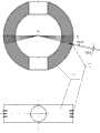
图2为一种用于河道宽度立体视觉检测的全景彩色结构光发生器的结构图;Fig. 2 is a structural diagram of a panoramic color structured light generator for stereoscopic vision detection of river channel width;
图3为基于主动立体全景视觉的河道宽度测量装置的原理图;Fig. 3 is the schematic diagram of the river channel width measurement device based on active stereo panoramic vision;
图4为河道截面实时测量装置的示意图;Figure 4 is a schematic diagram of a real-time measurement device for a river section;
图5为全方位视觉传感器成像原理图;Figure 5 is a schematic diagram of the imaging principle of the omnidirectional vision sensor;
图6为主动三维立体全景成像过程说明图;Fig. 6 is an explanatory diagram of an active three-dimensional panoramic imaging process;
图7为全方位视觉传感器和全景彩色结构光发生器在同一极线平面上的说明图;Fig. 7 is an explanatory diagram of an omnidirectional vision sensor and a panoramic color structured light generator on the same epipolar plane;
图8为点激光视觉测量示意图;Fig. 8 is a schematic diagram of point laser vision measurement;
图9为线激光视觉测量示意图;Fig. 9 is a schematic diagram of line laser vision measurement;
图10为面激光视觉测量示意图;Figure 10 is a schematic diagram of surface laser vision measurement;
图11为激光二极管控制线路图;Fig. 11 is a laser diode control circuit diagram;
图12为河道截面实时测量装置的处理流程图;Fig. 12 is the processing flowchart of the real-time measurement device for the river section;
图13为宽动态范围场景成像原理图;Fig. 13 is a schematic diagram of wide dynamic range scene imaging;
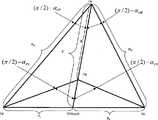
图14为河道宽度测量的模型图。Figure 14 is a model diagram of channel width measurement.
具体实施方式Detailed ways
下面结合附图对本发明作进一步描述。The present invention will be further described below in conjunction with the accompanying drawings.
实施例1Example 1
参照图1~7、图13~14,一种基于主动立体全景视觉的河道宽度测量装置,包括具有固定单一视点的全方位视觉传感器、具有固定单一发射中心点的全景彩色体结构光发生器以及用于对河道宽度进行三维立体摄像测量、河道地图数据获取、与河道深度数据融合的微处理器,所述全方位视觉传感器的视点与所述全景彩色体结构光发生器的发射中心点配置在同一根轴心线上;所述的基于主动立体全景视觉的河道宽度测量装置、所述的GPS传感器和所述的声纳传感器配置均固定在同一立杆延长线上,如附图4所示,所述的立杆固定在测量船舶的中心位置并与水平面垂直;Referring to Figures 1 to 7 and Figures 13 to 14, a river channel width measurement device based on active stereo panoramic vision includes an omnidirectional visual sensor with a fixed single point of view, a panoramic color volume structured light generator with a fixed single emission center point, and A microprocessor for three-dimensional camera measurement of the width of the river, acquisition of river map data, and fusion with river depth data, the viewpoint of the omnidirectional visual sensor and the emission center of the panoramic color volume structured light generator are arranged On the same axis; the described river channel width measuring device based on active stereo panoramic vision, the described GPS sensor and the described sonar sensor configuration are all fixed on the same pole extension line, as shown in Figure 4 , the pole is fixed at the center of the measuring ship and is perpendicular to the horizontal plane;
所述全方位视觉传感器包括双曲面镜面2、上盖1、透明半圆形外罩3、下固定座4、摄像单元固定座5、摄像单元6、连接单元7、上罩8,如附图1所示;所述的双曲面镜面2固定在所述的上盖1上,所述的连接单元7将所述的下固定座4和透明半圆形外罩3连接成一体,所述的透明半圆形外罩3与所述的上盖1以及所述的上罩8通过螺钉固定在一起,所述的摄像单元6用螺钉固定在所述的摄像单元固定座5上,所述的摄像单元固定座5用螺钉固定在所述的下固定座4上,所述全方位视觉传感器中的所述的摄像单元6的输出与所述微处理器连接;所述的摄像单元6是宽动态CMOS成像器件;Described omnidirectional vision sensor comprises
在宽动态CMOS成像器件中每个像素和一个数模转换相配套,因此强光像素降低了曝光量,低光像素相反增加曝光量。这个特点对于要获取全景视频图像的全方位视觉传感器来说具有十分重要的意义;这是因为一个CCD传感器可以调节亮景和暗景,但是不能同时对两个亮度进行调节。在原先的全方位视觉传感器中由于采用的是CCD传感器,当我们将原先的全方位视觉传感器安装在室内时,得到的曝光效果是不错的,可以比较清晰地获得室内的全景视频图像;而当我们将全方位视觉传感器移动到室内外的交界区域,全方位视觉传感器就不能很好的工作,室外的场景出现了过度曝光,不能捕捉到室外面的任何东西。在河道上使用中也会出现类似的问题,比如太阳光的照射是在不断变化的,在阳光斜射到全方位视觉传感器上时全方位视觉传感器就不能很好的工作,被阳光照射的一侧出现了过度曝光,成像时表现为白茫茫的一片;同时阳光斜射到水面上的镜面反射也会出现过度曝光现象。In the wide dynamic CMOS imaging device, each pixel is matched with a digital-to-analog conversion, so the strong light pixels reduce the exposure, and the low light pixels increase the exposure on the contrary. This feature is very important for omnidirectional vision sensors that want to capture panoramic video images; this is because a CCD sensor can adjust bright and dark scenes, but cannot adjust both brightness at the same time. In the original all-round vision sensor, because the CCD sensor is used, when we install the original all-round vision sensor indoors, the exposure effect obtained is good, and the indoor panoramic video image can be obtained relatively clearly; We moved the omni-directional vision sensor to the junction area between indoor and outdoor, and the omni-directional vision sensor could not work very well. The outdoor scene was overexposed and could not capture anything outside the room. Similar problems will also occur in the use on the river. For example, the sunlight is constantly changing. When the sunlight obliquely hits the omnidirectional vision sensor, the omnidirectional vision sensor cannot work well. The side illuminated by the sun There is overexposure, and it appears as a vast expanse of white when imaging; at the same time, the specular reflection of sunlight obliquely hitting the water surface will also appear overexposure.
人类的眼睛在不同的光照条件下具有自动调节功能,适用连续变化的光线,能看到最理想图像。当眼睛看到一幅包含亮光和暗光的场景时,能够减少对强光区域的敏感度,增加对黑暗物体和阴影部分的细节的敏感度。宽动态全方位视觉传感器采用一种新的CMOS传感器技术,保证了尽管前景是强光的条件下,阴影部分物体仍然清晰可见;强光区域的物体也不会消失,同时也能很好的抽取出激光照射的色彩信息,其原理图如附图13所示;The human eye has an automatic adjustment function under different lighting conditions, suitable for continuously changing light, and can see the most ideal image. When the eye sees a scene that contains both bright and dark lights, it can reduce its sensitivity to bright areas and increase its sensitivity to details in dark objects and shadows. The wide dynamic omni-directional vision sensor adopts a new CMOS sensor technology, which ensures that objects in the shadow part are still clearly visible despite the strong light in the foreground; objects in the strong light area will not disappear, and can also be well extracted The color information of laser irradiation is output, and its schematic diagram is shown in accompanying drawing 13;
所述的全景彩色体结构光发生器包括圆形面体基板9-1、3组具有不同发光中心波长的激光二极管LD9-2,如附图2所示;所述的激光二极管LD9-2固定在所述的圆形面体基板9-1上,所述的圆形面体基板为内部圆型中空、上下圆柱形中空的圆形面体,所述的圆形面体基板的外圆形面上从零纬度开始以相隔一定角度均匀等分排列着与激光二极管LD9-2的外直径相等的小孔,由于本发明中要获得河道边缘的信息,全景彩色体结构光发生器的安装高度高于水平面,为了能保证全景彩色体结构光发生器所发出的激光基本上都在河道边缘附近以提高投射角的分辨率,在设计中将所有激光二极管的投射角设计为0°~16°范围内,在同一纬度线上同时配置了三颗具有相同发光中心波长的激光二极管;所述的3组具有不同发光中心波长的激光二极管LD9-2依次从在所述的圆形面体基板上的零纬度值(0°)到最大俯角(16°)按顺序插入到相应的小孔内,每个激光二极管的发射光方向与所插入相应小孔的法线方向重合;The panoramic color body structured light generator includes a circular surface substrate 9-1, 3 groups of laser diodes LD9-2 with different central wavelengths of light emission, as shown in Figure 2; the laser diodes LD9-2 are fixed on On the circular surface substrate 9-1, the circular surface substrate is a circular surface with a circular hollow inside and a cylindrical hollow up and down. The outer circular surface of the circular surface substrate is from zero latitude Began to arrange the small holes equal to the outer diameter of the laser diode LD9-2 evenly at a certain angle, because the information on the edge of the river will be obtained in the present invention, the installation height of the panoramic color body structured light generator is higher than the horizontal plane, for It can ensure that the laser emitted by the panoramic color volume structured light generator is basically near the edge of the river to improve the resolution of the projection angle. In the design, the projection angle of all laser diodes is designed within the range of 0°~16°. Three laser diodes with the same central wavelength of light emission are simultaneously arranged on the latitude line; the three groups of laser diodes LD9-2 with different central wavelengths of light emission sequentially start from the zero latitude value (0 °) to the maximum depression angle (16°) are inserted into the corresponding small holes in sequence, and the light emitting direction of each laser diode coincides with the normal direction of the inserted corresponding small hole;
所述的基于主动立体全景视觉的河道宽度测量装置,通过连接杆10(也称为立杆)将所述的全景彩色体结构光发生器和所述的全方位视觉传感器连接起来,如附图3所示,连接杆10的上部的法兰通过螺钉固定全方位视觉传感器,全景彩色体结构光发生器套在连接杆10中并用螺钉进行固定,全景彩色体结构光发生器上的圆形面体基板平面正对着测量船的航行方向,这种连接方式保证了所述的全景彩色体结构光发生器的发射中心Op和所述的全方位视觉传感器的视点Ov在同一轴心线上,全方位视觉传感器的电源线、视频数据线以及全景彩色体结构光发生器的电源线均从连接杆10的中孔内穿出,连接到供电电源以及微处理器的相应接口上;当供电电源给全景彩色体结构光发生器供电时,所述的全景彩色体结构光发生器将从测量船的两侧发出扇形面全景彩色体结构光,所有光的发光中心点在全景彩色体结构光发生器的圆形面体的中心点上;The described river width measurement device based on active stereo panoramic vision connects the panoramic color body structured light generator and the omnidirectional visual sensor through a connecting rod 10 (also called a vertical rod), as shown in the accompanying drawing As shown in 3, the flange on the top of the connecting
目前已开发出并投放市场的半导体激光器的波段有370nm、390nm、405nm、430nm、473nm、532nm、593nm、635nm、650nm、670nm、780nm、808nm、850nm、980nm、1310nm、1550nm等,其中1310nm、1550nm主要用于光纤通讯领域。390nm-370nm为紫外光波段,405nm-670nm为可见光波段,780nm-1550nm为红外光波段。本发明中将采用可见光波段的半导体激光器,其中心波长在405nm、430nm、473nm、532nm、593nm、635nm、650nm、670nm,每个半导体激光器LD9-2的光线发射方向与圆形面体9-1的法线方向重合,这样产生的所有彩色光均是从圆形面体9-1的中心向外发射,所形成的彩色结构光与所述全景彩色体结构光发生器上某个半导体激光器LD所处的纬度值αp之间具有一定的函数关系,因此只要得到某一个光的波长就可以估算出全景彩色体结构光发生器的纬度值αp,即发光体的俯角;The wavelength bands of semiconductor lasers that have been developed and put on the market are 370nm, 390nm, 405nm, 430nm, 473nm, 532nm, 593nm, 635nm, 650nm, 670nm, 780nm, 808nm, 850nm, 980nm, 1310nm, 1550nm, etc., of which 1310nm, 1550nm It is mainly used in the field of optical fiber communication. 390nm-370nm is the ultraviolet light band, 405nm-670nm is the visible light band, and 780nm-1550nm is the infrared light band. Will adopt the semiconductor laser of visible light band in the present invention, its central wavelength is at 405nm, 430nm, 473nm, 532nm, 593nm, 635nm, 650nm, 670nm, the light emitting direction of each semiconductor laser LD9-2 and the circular surface 9-1 The normal direction coincides, so that all the colored lights produced are emitted outwards from the center of the circular surface body 9-1, and the formed colored structured light is in the same position as a certain semiconductor laser LD on the panoramic colored body structured light generator. There is a certain functional relationship between the latitude value αp, so as long as a certain wavelength of light is obtained, the latitude value αp of the panoramic color body structured light generator can be estimated, that is, the depression angle of the illuminant;
由于全景彩色体结构光发生器9的轴心和全方位视觉传感器的轴心相重叠,全景彩色体结构光发生器9的主动投影的经度必定是与全方位视觉传感器的方位角相一致的,从计算机视觉的角度来说,必定处在同一极平面上,如附图9所示;主动立体视觉的范围由附图4给出,在附图4中的斜线部分就是立体全景视觉的范围;Since the axis of the panoramic color volume structured light generator 9 overlaps with the axis of the omnidirectional vision sensor, the longitude of the active projection of the panoramic color volume structured light generator 9 must be consistent with the azimuth angle of the omnidirectional vision sensor. From the perspective of computer vision, it must be on the same polar plane, as shown in Figure 9; the range of active stereo vision is given by Figure 4, and the oblique line in Figure 4 is the range of stereo panoramic vision ;
根据上述的设计,当全景彩色体结构光发生器处于供电状态时,全景彩色体结构光发生器在纬度方向上形成了扇型状的呈按照角度函数关系变化的峰值波长的投射光,投射光从测量船的两侧发出并朝向河道边缘部位;如附图8所示,当空间上的一个点A(X,Y,Z),即河道的边缘点接受到一定波长的光,按照附图3的配置方式,投射到河道边缘点A(X,Y,Z)的光是蓝色光,波长为473nm,该光点A(X,Y,Z)继续向全方位视觉传感器的双曲面镜2反射,光线朝向全方位视觉传感器的双曲面镜2的实焦点,根据双曲面的镜面特性向着全方位视觉传感器的虚焦点14折反射,图5所示;反映实物图像的各具有一定波长的光点经全方位视觉传感器的双曲面镜2反射到聚光透镜中成像,在该成像平面上的一个点P(x,y)对应着实物在空间上的一个点的坐标A(X,Y,Z),成像光路图如图6中的粗实线所示;According to the above design, when the panoramic color volume structured light generator is in the power supply state, the panoramic color volume structured light generator forms a fan-shaped projected light with a peak wavelength that varies according to the angular function in the latitude direction, and the projected light Sent from both sides of the measuring ship and towards the edge of the river; as shown in Figure 8, when a point A (X, Y, Z) in space, that is, the edge of the river, receives light of a certain wavelength, according to the accompanying drawing 3 configuration, the light projected to the river edge point A (X, Y, Z) is blue light with a wavelength of 473nm, and the light point A (X, Y, Z) continues to the hyperbolic mirror 2 of the omnidirectional visual sensor Reflection, the light is towards the real focus of the hyperbolic mirror 2 of the omnidirectional visual sensor, according to the specular characteristics of the hyperboloid towards the virtual focal point 14 of the omnidirectional visual sensor, as shown in Figure 5; The point is reflected by the hyperboloid mirror 2 of the omnidirectional vision sensor into the condenser lens for imaging, and a point P(x, y) on the imaging plane corresponds to the coordinate A(X, Y, Z), the imaging optical path diagram is as shown in the thick solid line in Figure 6;
通过上述的设计,全景彩色体结构光发生器和全方位视觉传感器分别具有一个固定的发射中心点和一个固定的视点,并且这两个点处在同一对称中心轴的这两个特点;所谓的发射中心点对于全景彩色体结构光发生器来说是指全景彩色体结构光发生器的发射中心点,即圆形面体9-1的圆心,如附图6中的Op;对于全方位视觉传感器来讲是指全方位视觉传感器的折反射镜面的实焦点,如附图6中的Ov;通过全景彩色体结构光发生器和全方位视觉传感器的共同作用确定了河道边缘点A(X,Y,Z)在成像平面上点P(x,y)的投射角αp和入射角αo,即在成像平面上点P(x,y)上可以确定点A(X,Y,Z)的深度信息,即可以估算出河道边缘点到测量船的距离,如附图6(a)所示;Through the above design, the panoramic color volume structured light generator and the omnidirectional visual sensor have a fixed emission center point and a fixed viewpoint respectively, and these two points are on the same symmetrical central axis; the so-called The launch center point refers to the launch center point of the panoramic color volume structured light generator for the panoramic color volume structured light generator, that is, the center of circle of the circular surface body 9-1, as Op in accompanying drawing 6; for the omnidirectional visual sensor Generally speaking, it refers to the real focal point of the catadioptric mirror surface of the omnidirectional visual sensor, such as Ov among the accompanying
关于方位角,由于全景彩色体结构光发生器9的轴心和全方位视觉传感器的轴心相重叠,全景彩色体结构光发生器9的主动投影的经度必定是与全方位视觉传感器的方位角相一致,因此将全景彩色体结构光发生器9的主动投影的经度值作为全方位视觉传感器的方位角数据;Regarding the azimuth angle, since the axis of the panoramic color volume structured light generator 9 overlaps with the axis of the omnidirectional vision sensor, the longitude of the active projection of the panoramic color volume structured light generator 9 must be the same as the azimuth angle of the omnidirectional vision sensor. Consistent, therefore the longitude value of the active projection of the panoramic color volume structured light generator 9 is used as the azimuth data of the omnidirectional visual sensor;
进一步,介绍全方位视觉传感器的工作原理:进入双曲面镜的中心的光,根据双曲面的镜面特性向着其虚焦点折射。实物图像经双曲面镜反射到聚光透镜中成像,在该成像平面上的一个点P(x,y)对应着实物在空间上的一个点的坐标A(X,Y,Z);Further, the working principle of the omnidirectional vision sensor is introduced: the light entering the center of the hyperboloid mirror is refracted toward its virtual focus according to the specular characteristics of the hyperboloid. The image of the real object is reflected by the hyperboloid mirror into the condenser lens for imaging, and a point P (x, y) on the imaging plane corresponds to the coordinate A (X, Y, Z) of a point of the real object in space;
图5中的2--双曲线面镜,12-入射光线,13-双曲面镜的实焦点Om(0,0,c),14-双曲面镜的虚焦点,即摄像单元6的中心Oc(0,0,-c),15-反射光线,16-成像平面,17-实物图像的空间坐标A(X,Y,Z),18-入射到双曲面镜面上的图像的空间坐标,19-反射在成像平面上的点P(x,y);2--hyperbolic mirror in Fig. 5, 12-incident light, the real focal point Om (0, 0, c) of 13-hyperbolic mirror, the imaginary focal point of 14-hyperbolic mirror, i.e. the center Oc of camera unit 6 (0, 0, -c), 15-reflected light, 16-imaging plane, 17-space coordinates A (X, Y, Z) of the real image, 18-space coordinates of the image incident on the hyperboloid mirror surface, 19 - the point P(x,y) reflected on the imaging plane;
图5中所示的双曲面镜构成的光学系统可以由下面5个等式表示;The optical system that the hyperboloid mirror shown in Fig. 5 constitutes can be expressed by following 5 equations;
((X2+Y2)/a2)-((Z-c)2/b2)=-1当Z>0时 (1)((X2 +Y2 )/a2 )-((Zc)2 /b2 )=-1 when Z>0 (1)
β=tan-1(Y/X) (3)β=tan-1 (Y/X) (3)
α=tan-1[(b2+c2)sinγ-2bc]/(b2+c2)cosγ (4)α=tan-1 [(b2 +c2 )sinγ-2bc]/(b2 +c2 )cosγ (4)
式中X、Y、Z表示空间坐标,c表示双曲面镜的焦点,2c表示两个焦点之间的距离,a,b分别是双曲面镜的实轴和虚轴的长度,β表示入射光线在XY投影平面上与X轴的夹角,即方位角,α表示入射光线在XZ投影平面上与X轴的夹角,这里将α称为入射角,α大于或等于0时称为俯角,将α小于0时称为仰角,f表示成像平面到双曲面镜的虚焦点的距离,γ表示折反射光线与Z轴的夹角;x,y表示在成像平面上的一个点;In the formula, X, Y, and Z represent the space coordinates, c represents the focal point of the hyperbolic mirror, 2c represents the distance between the two focal points, a, b are the lengths of the real axis and imaginary axis of the hyperbolic mirror, respectively, and β represents the incident light The angle between the X-axis and the X-axis on the XY projection plane is the azimuth angle. α represents the angle between the incident light and the X-axis on the XZ projection plane. Here, α is called the incident angle, and when α is greater than or equal to 0, it is called the depression angle. When α is less than 0, it is called the elevation angle, f represents the distance from the imaging plane to the virtual focus of the hyperbolic mirror, and γ represents the angle between the refraction light and the Z axis; x, y represent a point on the imaging plane;
根据附图4所示河道宽度主动立体视觉测量方案中,关于河道场景的所有视频信息都处于全方位视觉传感器的实焦点Ov之下;为了使得全方位视觉传感器在关注的河道边缘区域内具有较高的成像分辨率,在所述的双曲面镜面2设计时需要尽可能将垂直方向的可视范围限制在俯角80°到20°范围内,如附图5所示;本发明中通过加大双曲面镜的实轴a和虚轴b的比来提高河道场景内成像分辨率;According to the active stereo vision measurement scheme of the river channel width shown in accompanying drawing 4, all video information about the channel scene is under the real focus Ov of the omnidirectional visual sensor; in order to make the omnidirectional visual sensor have a relatively High imaging resolution, in the design of the
具有某一特定波长的点将在全方位视觉传感器的成像平面上有一个对应点,即P(x,y),根据双曲面镜的折反射成像原理可通过公式(6)计算出该点的折反射光线与Z轴的夹角γo;有了折反射角γo,就可以通过公式(7)计算得到具有某一特定波长的点的入射角αo,A point with a specific wavelength will have a corresponding point on the imaging plane of the omnidirectional vision sensor, that is, P(x, y). According to the catadioptric imaging principle of the hyperbolic mirror, the The angle γo between the refraction light and the Z axis; with the refraction angle γo, the incident angle αo of a point with a certain wavelength can be calculated by formula (7),
αo=tan-1[(b2+c2)sinγo-2bc]/(b2+c2)cosγo(7)αo =tan-1 [(b2 +c2 )sinγo -2bc]/(b2 +c2 )cosγo (7)
由于某一波长光的波长的投射角αp与入射角αo均在同一极平面上,如附图7所示,有了这两个数据就能方便地得到空间点与观察点的位置深度和角度信息,即在全方位视觉传感器成像平面上的某一个像素点的位置代表入射角αo的信息,该像素点的色彩代表投射角αp的信息;Since the projection angle αp and the incident angle αo of a certain wavelength of light are on the same polar plane, as shown in Figure 7, with these two data, the position, depth and angle of the space point and the observation point can be easily obtained Information, that is, the position of a certain pixel on the imaging plane of the omnidirectional visual sensor represents the information of the incident angle αo, and the color of the pixel represents the information of the projection angle αp;
所述的微处理器中包括:河道宽度测量子系统、测量船舶位置检测子系统和河道深度检测子系统;所述的河道宽度测量子系统中包括:LD光源控制单元、视频图像读取模块、视频图像加工模块、河道宽度计算模块、河道截面图自动生成模块和存储设备;如附图12所示;The microprocessor includes: a river width measurement subsystem, a measuring ship position detection subsystem and a river depth detection subsystem; the river width measurement subsystem includes: an LD light source control unit, a video image reading module, A video image processing module, a channel width calculation module, a channel section diagram automatic generation module and a storage device; as shown in Figure 12;
所述的LD光源控制单元,用于控制全景彩色体结构光发生器发出全彩色全景结构光,在LD光源控制单元使全景彩色体结构光发生器的供电电源处于ON状态时,在全方位视觉传感器的成像单元中直接获得空间某物点的深度和方位角度信息;实际LD光源的供电电源开关控制采用如附图11所示的激光二极管控制电子回路来实现,当用软件接通电子开关K1~K8中的任何一个开关,激光二极管就会发光;反之将电子开关断开,激光二极管就不发光;The LD light source control unit is used to control the panoramic color volume structured light generator to emit full-color panoramic structured light. The imaging unit of the sensor directly obtains the depth and azimuth angle information of a certain point in space; the power supply switch control of the actual LD light source is realized by the laser diode control electronic circuit shown in Figure 11, when the electronic switch K1 is turned on by software ~ Any switch in K8, the laser diode will emit light; otherwise, turn off the electronic switch, and the laser diode will not emit light;
图11中BA5104是发射器芯片,K1~K8是控制输入端,内接上拉电阻。当接通其中任一控制输入端时,OSC1和OSC2脚所内接的时钟电路及外接455kHz晶体、电容C1、C2组成的振荡电路起振,经内部电路分频产生38kHz载频,经达林顿管D1581放大后驱动半导体激光管LD送出调制载波脉冲激光信号。电位器W用以调节激光管的工作电流,以使其处于额定工作电流之内。LED端是发射状态显示输出端,有高电平输出时,LED发亮。图11中的LD半导体激光二极管,是光电开关发射器的关键元件。In Figure 11, BA5104 is the transmitter chip, and K1-K8 are the control input terminals, which are internally connected with pull-up resistors. When any one of the control input terminals is connected, the internal clock circuit connected to OSC1 and OSC2 pins and the oscillator circuit composed of external 455kHz crystal, capacitors C1 and C2 will start to oscillate, and the frequency division of the internal circuit will generate a 38kHz carrier frequency. Tube D1581 amplifies and drives semiconductor laser tube LD to send out modulated carrier pulse laser signal. The potentiometer W is used to adjust the working current of the laser tube so that it is within the rated working current. The LED terminal is the output terminal for displaying the emission status. When there is a high-level output, the LED lights up. The LD semiconductor laser diode in Figure 11 is the key component of the photoelectric switch transmitter.
激光二极管与普通LED的原理相同,但能产生几倍的光能,并能达到更远的检测距离,检测距离可长达数百米至数公里,半导体激光光源是一种相干性强的光源,因而方向性很强,用光学系统准直后,可很容易的把发散角限制在0.2mrad以内。激光照射的光斑大小可按下式近似计算:The principle of laser diode is the same as that of ordinary LED, but it can generate several times the light energy and achieve a longer detection distance. The detection distance can be as long as hundreds of meters to several kilometers. Semiconductor laser light source is a kind of light source with strong coherence , so the directionality is very strong. After collimating with the optical system, the divergence angle can be easily limited within 0.2mrad. The spot size of laser irradiation can be approximated by the following formula:
d=L×θ (14)d=L×θ (14)
式中,d为光斑直径(mm);L为检测距离(m);θ为发散角(mrad)。Where, d is the spot diameter (mm); L is the detection distance (m); θ is the divergence angle (mrad).
若一束激光投射到500m远处,可近似得光斑直径为100mm,可见光斑并不大,在此范围内仍有较大的能量分布。因此,有时需要从检测距离来确定激光二极管的发散角,一般测量距离远需要采用小的发散角激光二极管,对于测量距离近则可以采用大的发散角激光二极管。If a laser beam is projected to a distance of 500m, the diameter of the spot can be approximated as 100mm, and the visible spot is not large, and there is still a large energy distribution within this range. Therefore, sometimes it is necessary to determine the divergence angle of the laser diode from the detection distance. Generally, a laser diode with a small divergence angle is required for a long measurement distance, and a laser diode with a large divergence angle can be used for a short measurement distance.
进一步,采用激光激光对人体,特别是人眼有严重伤害,使用时需特别小心。国际上对激光有统一的分类和统一的安全警示标志,根据激光对人体的危险度分类,在光树内观察对眼睛的MPE(maximal possible effect最大可能的影响)做基准,激光器分为四类(Class1~Class4),一类激光器对人是安全的,二类激光器对人有较轻的伤害,三类以上的激光器对人有严重伤害,使用时需特别注意,避免对人眼直射。本发明中为了测量较远的距离采用二类激光器,即Class II级:低输出的可视激光(功率0.4mW-1mW),人闭合眼睛的反应时间为0.25秒,用这段时间算出的曝光量不可以超过MPE值。通常1mW以下的激光,正常暴露在这种激光器的光束下不会对眼睛的视网膜造成永久性的伤害,但是会导致晕眩,本发明中采用间断式的照射,每次照射时间都为一秒以下,因此该装置对人眼来说是安全的。Furthermore, the use of lasers can cause serious damage to the human body, especially the human eyes, so special care must be taken when using them. Internationally, there is a unified classification and unified safety warning signs for lasers. According to the classification of the danger of lasers to the human body, the MPE (maximal possible effect) of the eyes observed in the light tree is used as a benchmark. Lasers are divided into four categories. (Class1~Class4),
所述的视频图像读取模块,用于读取全方位视觉传感器的视频图像,并保存在所述的存储设备中,其输出与所述的空间信息计算模块连接;在全景彩色体结构光发生器的供电电源处于ON状态时所读取的全景视频图像中的各像素色彩带有某物点的深度和方位角度信息;如附图6所示;比如在附图8(a)中某物点的像素P(i,j)中读取的颜色为蓝色,该颜色表示全景彩色体结构光发生器的投射角αp为南纬6°,根据双曲面镜的成像原理通过公式(6)、(7)计算成像平面上的P(i,j)的入射角αo,通过投射角αp、入射角αo以及全景彩色体结构光发生器的中心点和全方位视觉传感器的实焦点Om之间的距离得到空间物点(河道边缘点)的深度信息;The video image reading module is used to read the video image of the omnidirectional visual sensor and store it in the storage device, and its output is connected to the spatial information calculation module; Each pixel color in the panoramic video image read when the power supply of the device is in the ON state has depth and azimuth angle information of a certain object point; as shown in accompanying drawing 6; for example in accompanying drawing 8 (a) a certain object The color read in the pixel P(i, j) of the point is blue, which means that the projection angle αp of the panoramic color volume structured light generator is 6° south latitude. According to the imaging principle of the hyperboloid mirror, the formula (6) , (7) Calculate the incident angle αo of P(i, j) on the imaging plane, through the projection angle αp, the incident angle αo and the center point of the panoramic color body structured light generator and the real focus Om of the omnidirectional visual sensor The distance to get the depth information of the spatial object point (edge point of the river channel);
所述的视频图像加工模块,用于在获取的全景视频图像上添加测量船的位置信息和该位置上的水深信息,以便后续人机交互、修正河道自动视频测量中的错检与漏检;The video image processing module is used to add the position information of the measuring ship and the water depth information at the position to the obtained panoramic video image, so as to facilitate subsequent human-computer interaction and correct false detection and missed detection in the automatic video measurement of the river channel;
所述的河道宽度计算模块,用于计算河道边缘上的点到基于主动立体全景视觉的河道宽度测量装置的中心点的距离及入射角,分别计算河道两侧边缘点与全方位视觉传感器的实焦点Om的距离RL1、RR1,河道两侧边缘点与测量船立杆中心点的距离BL、BR;其输出与河道截面图自动生成模块连接;The channel width calculation module is used to calculate the distance and incident angle from the point on the edge of the channel to the center point of the channel width measuring device based on active stereo panoramic vision, and calculate the actual distance between the edge points on both sides of the channel and the omnidirectional visual sensor respectively. The distances RL1 and RR1 of the focal point Om , the distances BL and BR between the edge points on both sides of the river channel and the center point of the vertical pole of the survey boat; its output is connected with the automatic generation module of the channel cross-sectional view;
所述的河道宽度计算模块包括测量船两侧河道边缘点的左侧投射角αPL和右侧投射角αPR计算单元、左侧入射角αOL和右侧入射角αOR计算单元、左侧距离BL和右侧距离BR计算单元;The channel width calculation module includes a left projection angle αPL and a right projection angle αPR calculation unit, a left incident angle α OL and a right incident angle α OR calculation unit, a left side incident angle αOL and a right incident angle αOR calculation unit of the channel edge points on both sides of the measuring ship Calculation unit of distanceBL and right distanceBR ;
所述的左侧投射角αPL和右侧投射角αPR计算单元,用于利用彩色全景投影的投射角αp与彩色全景投影中某个激光半导体LD所发射出的光波长之间具有一定的函数关系来计算的,当全景彩色体结构光发生器的供电电源处于ON状态时,成像平面上的像素的色彩分量与投射角αp存在一一对应关系,利用该关系来得到左侧投射角αPL和右侧投射角αPR;The left projection angle αPL and the right projection angle αPR calculation unit are used to utilize a certain distance between the projection angle αp of the color panoramic projection and the wavelength of light emitted by a certain laser semiconductor LD in the color panoramic projection. When the power supply of the panoramic color volume structured light generator is in the ON state, there is a one-to-one correspondence between the color components of the pixels on the imaging plane and the projection angle αp, and use this relationship to get the left projection angle αPL and right projection angle αPR ;
所述的左侧入射角αOL和右侧入射角αOR计算单元,用于利用全方位视觉传感器的入射角αOL、αOR与折反射角γOL、γOR之间存在着公式(9)所示的函数关系,The left angle of incidence αOL and the right angle of incidence αORcalculation unit are usedto utilizethe formula (9 ) shows the functional relationship,
αOL=tan-1[(b2+c2)sinγOL-2bc]/(b2+c2)cosγOLαOL =tan−1 [(b2 +c2 )sinγOL −2bc]/(b2 +c2 )cosγOL
αOR=tan-1[(b2+c2)sinγOR-2bc]/(b2+c2)cosγOR (9)αOR =tan−1 [(b2 +c2 )sinγOR −2bc]/(b2 +c2 )cosγOR (9)
折反射角γOL、γOR与成像平面上的河道左右侧边缘点L(x1,y1)、R(x2,y2)存在着公式(10)所示的函数关系,The refraction angles γOL , γOR have a functional relationship with the left and right edge points L(x1, y1) and R(x2, y2) of the channel on the imaging plane as shown in formula (10),
通过公式(9)和(10)可得到成像平面上的河道左右侧边缘点L(x1,y1)、R(x2,y2)与左侧入射角αOL和右侧入射角αOR之间的函数关系;当得到了左侧投射角αPL、右侧投射角αPR、左侧入射角αOL和右侧入射角αOR这些信息后,实际河道左右侧边缘点Lp、Rp也就确定了,如附图14所示;Through formulas (9) and (10), the relationship between the left and right side edge points L(x1, y1) and R(x2, y2) of the river on the imaging plane and the left incident angle αOL and the right incident angle αOR can be obtained function relationship; when the left projection angle αPL , right projection angle αPR , left incident angle αOL and right incident angle αOR are obtained, the actual left and right side edge points Lp and Rp of the river are also determined , as shown in accompanying drawing 14;
所述的左侧距离BL和右侧距离BR计算单元,测量船的中心点位置由GPS定位系统来确定,如附图14中的BO点;这里需要考虑测量船摇摆的影响,不能用直角三角型的计算公式,本发明中利用正弦和余弦定理来计算所述的左侧距离BL和右侧距离BR,公式(11)~(12)分别计算成像平面上的河道左右侧边缘点与全方位视觉传感器的实焦点Ov的距离RL1、RR1,然后根据RL1 RR1以及αOL、αOR计算测量船中心点到河道边缘的左侧距离BL和到河道边缘的右侧距离BR,In the left side distanceBL and the right side distanceBR calculation unit, the center point position of the measuring ship is determined by the GPS positioning system, such as the BO point in the accompanying drawing 14; the influence of the measuring ship's swing needs to be considered here, and cannot be used The calculation formula of the right-angled triangle type uses the sine and cosine theorem to calculate the left side distanceBL and the right side distanceBR in the present invention, and the formulas (11)~(12) calculate the left and right side edges of the river on the imaging plane respectively point and the real focal point Ov of the omnidirectional visual sensor RL1 , RR1 , and then according to RL1 RR1 and αOL , αOR calculate the left distanceBL from the center point of the ship to the edge of the channel and the distance to the edge of the channel Right distance BR ,
B(x,y)=BL(x,y)+BR(x,y)B(x, y) = BL (x, y) + BR (x, y)
式中:B为基线距,即投影光源中心点Op与全方位视觉传感器的实焦点Ov之间的距离,H为测量船的立杆上的全方位视觉传感器的实焦点Ov与立杆和水平面相交点之间的距离,αOL为河道左侧边缘点入射角,αOR为河道右侧边缘点入射角,αPL为河道左侧边缘点投射角,αPR为河道右侧边缘点投射角,BL(x,y)为河道左侧边缘点与测量船中心点BO(x,y,z)之间的距离,BR(x,y)为河道右侧边缘点与测量船中心点BO(x,y,z)之间的距离,B(x,y)为在船舶中心点位于BO(x,y,z)时的河道宽度。In the formula: B is the baseline distance, that is, the distance between the center point Op of the projection light source and the real focus Ov of the omnidirectional visual sensor; The distance between the intersection points, αOL is the incident angle of the left edge of the river, αOR is the incident angle of the right edge of the river, αPL is the projection angle of the left edge of the river, αPR is the projection angle of the right edge of the river ,BL(x, y) is the distance between the left edge point of the channel and the center point BO(x, y, z) of the survey ship, BR(x, y) is the distance between the right edge point of the channel and the center point of the survey ship The distance between BO(x, y, z), B(x, y) is the channel width when the center point of the ship is located at BO(x, y, z).
再进一步,在所述的左侧距离BL和右侧距离BR计算单元中,设置一张光编码表来实现某一光波长λ与某一投射角αp之间存在的映射关系,这里某一投射角αp是泛指,具体根据河道左右边缘点有αPL和αPR;一张入射角计算表来实现某一个点的坐标数据与该点所对应的入射角αo之间存在的映射关系,这里入射角αo是泛指,具体根据河道左右边缘点有αOL、αOR;投射角αp、入射角αo计算采用查表方式实现;首先在全景彩色体结构光发生器的供电电源处于ON状态时按全方位视觉传感器的成像平面的点坐标顺序读取某一个像素点的波长λ值,以点坐标值检索入射角计算表得到该点所对应的入射角αo,接着以该点的光波长λ值检索光编码表得到该光波长λ所对应的投射角αp;最后利用公式(11)计算得到船舶中心点到河道左右边缘点之间的距离信息,利用公式(12)计算得到在船舶中心点位于BO(x,y,z)时的河道宽度;Furthermore, in the calculation unit of the left distanceBL and the right distanceBR , an optical encoding table is set to realize the mapping relationship between a certain light wavelength λ and a certain projection angle αp, where a certain A projection angle αp refers to it in general, specifically according to the left and right edge points of the river channel, there are αPL and αPR ; an incident angle calculation table is used to realize the mapping relationship between the coordinate data of a certain point and the incident angle αo corresponding to the point , where the incident angle αo refers generally, specifically according to the left and right edge points of the river, there are αOL and αOR ; the calculation of the projection angle αp and the incident angle αo is realized by look-up table; firstly, when the power supply of the panoramic color volume structured light generator is ON In the state, read the wavelength λ value of a certain pixel point according to the point coordinates of the imaging plane of the omnidirectional vision sensor, and retrieve the incident angle calculation table with the point coordinate value to obtain the incident angle αo corresponding to the point, and then use the light of the point The wavelength λ value searches the optical code table to obtain the projection angle αp corresponding to the light wavelength λ; finally, the distance information between the center point of the ship and the left and right edge points of the river is calculated by using the formula (11), and the distance information between the ship center point and the left and right edge points of the river is calculated by using the formula (12). The width of the channel when the center point is located at BO(x, y, z);
再进一步,我们可以设计一张投射角αp与颜色波长λ值的关系表,如表1所示;Going a step further, we can design a relationship table between the projection angle αp and the color wavelength λ, as shown in Table 1;
表1投射角αp与相应颜色波长λ值对应表Table 1 Correspondence between projection angle αp and corresponding color wavelength λ value
如果在成像平面的某个像素点上获得的色彩波长为540nm,根据查表,可以得到该颜色波长在绿色532nm和浅绿黄色593nm之间,可以通过插值计算得到在色彩波长为540nm时的投射角αp为南纬6.26°;插值计算如公式(13)所示,If the color wavelength obtained on a certain pixel of the imaging plane is 540nm, according to the look-up table, it can be obtained that the color wavelength is between green 532nm and light green yellow 593nm, and the projection when the color wavelength is 540nm can be obtained by interpolation calculation The angle αp is 6.26° south latitude; the interpolation calculation is shown in formula (13),
式中,λn-1、λn分别为已知某颜色波长λp的相邻的颜色中心波长,αn-1、αn分别为已知某颜色波长λp的相邻的投射角。In the formula, λn-1 and λn are the adjacent color center wavelengths of the known wavelength λp of a certain color, respectively, and αn-1 and αn are the adjacent projection angles of the known wavelength λp of a certain color.
Claims (7)
Translated fromChinesePriority Applications (1)
| Application Number | Priority Date | Filing Date | Title |
|---|---|---|---|
| CN200910102320ACN101776452A (en) | 2009-08-28 | 2009-08-28 | Active three-dimensional omnidirectional vision-based river width measuring device |
Applications Claiming Priority (1)
| Application Number | Priority Date | Filing Date | Title |
|---|---|---|---|
| CN200910102320ACN101776452A (en) | 2009-08-28 | 2009-08-28 | Active three-dimensional omnidirectional vision-based river width measuring device |
Publications (1)
| Publication Number | Publication Date |
|---|---|
| CN101776452Atrue CN101776452A (en) | 2010-07-14 |
Family
ID=42512974
Family Applications (1)
| Application Number | Title | Priority Date | Filing Date |
|---|---|---|---|
| CN200910102320APendingCN101776452A (en) | 2009-08-28 | 2009-08-28 | Active three-dimensional omnidirectional vision-based river width measuring device |
Country Status (1)
| Country | Link |
|---|---|
| CN (1) | CN101776452A (en) |
Cited By (8)
| Publication number | Priority date | Publication date | Assignee | Title |
|---|---|---|---|---|
| CN102313547A (en)* | 2011-05-26 | 2012-01-11 | 东南大学 | Visual navigation method for mobile robot based on hand-drawn contour semantic map |
| CN104508423A (en)* | 2012-05-16 | 2015-04-08 | 伊斯拉视像系统股份公司 | Method and device for inspecting surfaces of an examined object |
| CN104567818B (en)* | 2014-12-31 | 2016-09-28 | 浙江工业大学 | A kind of portable round-the-clock actively panoramic vision sensor |
| CN108267127A (en)* | 2018-03-07 | 2018-07-10 | 中国葛洲坝集团第工程有限公司 | Bathymetric surveying system and method |
| CN108694713A (en)* | 2018-04-19 | 2018-10-23 | 北京控制工程研究所 | A kind of the ring segment identification of satellite-rocket docking ring part and measurement method based on stereoscopic vision |
| CN112146855A (en)* | 2019-06-28 | 2020-12-29 | 常州星宇车灯股份有限公司 | Calibration method, calibration device and calibration system |
| CN112985362A (en)* | 2021-02-20 | 2021-06-18 | 浙江数智交院科技股份有限公司 | Inland waterway chart updating system and method based on cloud network interaction |
| CN113222833A (en)* | 2021-04-14 | 2021-08-06 | 武汉环达电子科技有限公司 | Side-scan sonar image processing method and device |
- 2009
- 2009-08-28CNCN200910102320Apatent/CN101776452A/enactivePending
Cited By (10)
| Publication number | Priority date | Publication date | Assignee | Title |
|---|---|---|---|---|
| CN102313547A (en)* | 2011-05-26 | 2012-01-11 | 东南大学 | Visual navigation method for mobile robot based on hand-drawn contour semantic map |
| CN104508423A (en)* | 2012-05-16 | 2015-04-08 | 伊斯拉视像系统股份公司 | Method and device for inspecting surfaces of an examined object |
| US9709390B2 (en) | 2012-05-16 | 2017-07-18 | Isra Vision Ag | Method and a device for the inspection of surfaces of an examined object |
| CN104567818B (en)* | 2014-12-31 | 2016-09-28 | 浙江工业大学 | A kind of portable round-the-clock actively panoramic vision sensor |
| CN108267127A (en)* | 2018-03-07 | 2018-07-10 | 中国葛洲坝集团第工程有限公司 | Bathymetric surveying system and method |
| CN108267127B (en)* | 2018-03-07 | 2024-05-03 | 中国葛洲坝集团第一工程有限公司 | Underwater topography measurement system and method |
| CN108694713A (en)* | 2018-04-19 | 2018-10-23 | 北京控制工程研究所 | A kind of the ring segment identification of satellite-rocket docking ring part and measurement method based on stereoscopic vision |
| CN112146855A (en)* | 2019-06-28 | 2020-12-29 | 常州星宇车灯股份有限公司 | Calibration method, calibration device and calibration system |
| CN112985362A (en)* | 2021-02-20 | 2021-06-18 | 浙江数智交院科技股份有限公司 | Inland waterway chart updating system and method based on cloud network interaction |
| CN113222833A (en)* | 2021-04-14 | 2021-08-06 | 武汉环达电子科技有限公司 | Side-scan sonar image processing method and device |
Similar Documents
| Publication | Publication Date | Title |
|---|---|---|
| CN101655347B (en) | Active 3D Stereo Omnidirectional Vision Sensor Based on Laser Diode Light Source | |
| CN101650176B (en) | Traffic accident scene surveying instrument based on active, stereoscopic and omnibearing vision | |
| CN101776452A (en) | Active three-dimensional omnidirectional vision-based river width measuring device | |
| CN109375237B (en) | A kind of all solid state face array three-dimensional imaging laser radar system | |
| US20240087227A1 (en) | Solar access measurement | |
| CN101487703B (en) | Fast Panoramic Stereo Camera Measuring Device | |
| CN101619962B (en) | Active three-dimensional panoramic view vision sensor based on full color panoramic view LED light source | |
| Breugnot et al. | Modeling and performances of a polarization active imager at λ= 806nm | |
| CN106772431A (en) | A kind of Depth Information Acquistion devices and methods therefor of combination TOF technologies and binocular vision | |
| CN109076148A (en) | Daily scene reconstruction engine | |
| CN102305598B (en) | Underwater photography measurement method for profile accuracy of semi-rigid self-resilience reflector | |
| CN105548964A (en) | Indoor visible light positioning method on the basis of light source imaging | |
| CN101363918B (en) | A Method for Locating and Recognizing Objects Using Solar Blind Ultraviolet Light | |
| CN104567818B (en) | A kind of portable round-the-clock actively panoramic vision sensor | |
| WO2016184255A1 (en) | Visual positioning device and three-dimensional mapping system and method based on same | |
| CN104410839A (en) | Mobile online monitoring system for mountain fire and landslide hazards in power transmission line pole and tower region and monitoring method | |
| CN102800123A (en) | Portable image holography three-dimensional reconstruction system | |
| CN113804165B (en) | Unmanned aerial vehicle simulation GPS signal positioning method and device | |
| CN208689169U (en) | A kind of indoor three-dimensional mapping device based on single line laser radar and target | |
| CN115900656A (en) | Real estate mapping project regional mapping method and system based on unmanned aerial vehicle | |
| Kuželka et al. | Mathematically optimized trajectory for terrestrial close-range photogrammetric 3D reconstruction of forest stands | |
| CN101614947B (en) | Color panoramic projective light source for initiative three-dimensional panoramic vision | |
| CN211291443U (en) | Passive telemetering robot based on live-action three-dimensional map | |
| CN113567352B (en) | Ocean oil spill detection method and device based on polarized hemispherical airspace irradiation | |
| CN113835098B (en) | Laser water depth measuring system and method |
Legal Events
| Date | Code | Title | Description |
|---|---|---|---|
| C06 | Publication | ||
| PB01 | Publication | ||
| C10 | Entry into substantive examination | ||
| SE01 | Entry into force of request for substantive examination | ||
| C12 | Rejection of a patent application after its publication | ||
| RJ01 | Rejection of invention patent application after publication | Open date:20100714 |