CN101773400B - Minimally invasive surgical robot master control data gloves - Google Patents
Minimally invasive surgical robot master control data glovesDownload PDFInfo
- Publication number
- CN101773400B CN101773400BCN2010100313794ACN201010031379ACN101773400BCN 101773400 BCN101773400 BCN 101773400BCN 2010100313794 ACN2010100313794 ACN 2010100313794ACN 201010031379 ACN201010031379 ACN 201010031379ACN 101773400 BCN101773400 BCN 101773400B
- Authority
- CN
- China
- Prior art keywords
- joint
- potentiometer
- shaft
- control mechanism
- thumb
- Prior art date
- Legal status (The legal status is an assumption and is not a legal conclusion. Google has not performed a legal analysis and makes no representation as to the accuracy of the status listed.)
- Expired - Fee Related
Links
- 210000003811fingerAnatomy0.000claimsabstractdescription136
- 230000007246mechanismEffects0.000claimsabstractdescription119
- 210000003813thumbAnatomy0.000claimsabstractdescription67
- 210000000245forearmAnatomy0.000claimsabstractdescription26
- 238000005259measurementMethods0.000claimsdescription35
- 210000000707wristAnatomy0.000claimsdescription34
- 230000008878couplingEffects0.000claimsdescription22
- 238000010168coupling processMethods0.000claimsdescription22
- 238000005859coupling reactionMethods0.000claimsdescription22
- 210000005224forefingerAnatomy0.000claimsdescription17
- 230000009916joint effectEffects0.000claimsdescription14
- 230000009471actionEffects0.000claimsdescription9
- 229910000831SteelInorganic materials0.000claimsdescription5
- 239000010959steelSubstances0.000claimsdescription5
- 230000000694effectsEffects0.000claimsdescription2
- 230000008520organizationEffects0.000claims15
- 210000003797carpal jointAnatomy0.000claims3
- 210000003857wrist jointAnatomy0.000abstractdescription19
- 238000002324minimally invasive surgeryMethods0.000abstractdescription5
- 210000000115thoracic cavityAnatomy0.000abstractdescription3
- 230000033001locomotionEffects0.000description32
- 230000005540biological transmissionEffects0.000description10
- 238000010586diagramMethods0.000description7
- 210000001145finger jointAnatomy0.000description3
- 210000000683abdominal cavityAnatomy0.000description2
- 238000000034methodMethods0.000description2
- 208000027418Wounds and injuryDiseases0.000description1
- 230000009286beneficial effectEffects0.000description1
- 230000008859changeEffects0.000description1
- 238000013461designMethods0.000description1
- 238000011161developmentMethods0.000description1
- 238000005516engineering processMethods0.000description1
- 208000014674injuryDiseases0.000description1
- 239000000203mixtureSubstances0.000description1
- 238000012986modificationMethods0.000description1
- 230000004048modificationEffects0.000description1
- 230000008569processEffects0.000description1
- 238000001356surgical procedureMethods0.000description1
- 230000008733traumaEffects0.000description1
Images


Landscapes
- Manipulator (AREA)
Abstract
Description
Translated fromChinese技术领域technical field
本发明涉及一种微创外科手术机器人主控数据手套。特别是涉及一种测量操作者手在三维空间中所处位置,测量操作者手臂、手腕、拇指、食指、中指关节动作的控制设备,使用方便、操作灵活的微创外科手术机器人主控设备。The invention relates to a minimally invasive surgery robot master control data glove. In particular, it relates to a control device for measuring the position of the operator's hand in three-dimensional space, measuring the joint movements of the operator's arm, wrist, thumb, index finger, and middle finger, and a master control device for a minimally invasive surgical robot that is easy to use and flexible to operate.
背景技术Background technique
微创手术是借助先进的手术器械与设备、以较小的创伤完成手术,达到优于传统开口手术的疗效。机器人技术进入微创外科手术领域后,为完成复杂的手术操作,机器人末端工具要求有较高灵活性,末端工具由最初的单自由度构型发展为多自由度、多功能形式。机器人末端工具由医生通过主操作器进行控制,随着末端工具的发展,其自由度数增加,拓扑结构可进行变化。手形多功能、多自由度机器人微创手术工具出现以后,现有的微创外科手术机器人主控制器无法满足其控制需求,如:公开日为2009年6月3日的中国发明专利申请公开了一种用于辅助微创外科手术机器人的三维力反馈主操作手,底座机构包括底座、立柱,一个扇形底板安装在立柱顶面上;四连杆机构包括安装在弧形底板上的弧形支架,上下近架杆、上下远架杆组组成的平行四边体机构;所述的手腕机构包括腕体,在腕体上部设置有第五伸出轴,一个指节的一端套在第五伸出轴上;指节的另一端通过轴承套在设置在一个指柄座上的第六伸出轴上;在所述的指柄座上通过轴承连接有两个指柄轴,所述的两个指柄轴之间通过齿轮相啮合配合,在所述的每一指柄轴上粘结有一个指柄。虽然,上述主操作手的手腕机构三个转动自由度的旋转中心交于一点,并且将工作点置于该汇交点的设计,可以实现六轴联动。但该主操作手只能控制简单结构的微创外科手术机器人末端工具。Minimally invasive surgery is to use advanced surgical instruments and equipment to complete the operation with less trauma, and achieve better curative effect than traditional open surgery. After robotics technology entered the field of minimally invasive surgery, in order to complete complex surgical operations, the end tool of the robot requires high flexibility, and the end tool has developed from the initial single-degree-of-freedom configuration to a multi-degree-of-freedom, multi-functional form. The end tool of the robot is controlled by the doctor through the main manipulator. With the development of the end tool, the number of degrees of freedom increases and the topology can be changed. After the emergence of hand-shaped multifunctional and multi-degree-of-freedom robot minimally invasive surgical tools, the existing minimally invasive surgical robot main controller cannot meet its control requirements. A three-dimensional force feedback main operator for assisting a minimally invasive surgical robot. The base mechanism includes a base and a column, and a fan-shaped bottom plate is installed on the top surface of the column; the four-bar linkage mechanism includes an arc-shaped bracket installed on the arc-shaped bottom plate , a parallelogram mechanism composed of upper and lower near frame rods and upper and lower far frame rod groups; the wrist mechanism includes a wrist body, a fifth extension shaft is arranged on the upper part of the wrist body, and one end of a knuckle is placed on the fifth extension shaft. on the shaft; the other end of the knuckle is sleeved on the sixth extension shaft provided on a finger handle seat through a bearing sleeve; two finger handle shafts are connected by bearings on the finger handle seat, and the two The finger shafts are meshed and matched by gears, and a finger handle is bonded to each of the finger shafts. Although, the rotation centers of the three rotational degrees of freedom of the above-mentioned master operator's wrist mechanism intersect at one point, and the design of placing the working point at the intersection point can realize six-axis linkage. But the master operator can only control the minimally invasive surgical robot end tool with simple structure.
迄今为止,在微创外科手术机器人主控制器领域,用来同时测量操作者手臂、手腕、拇指、食指、中指关节动作及手的空间位置,控制多功能、多自由度机器人微创手术工具的主操作手,没有得到开发与使用。So far, in the field of minimally invasive surgical robot main controller, it is used to simultaneously measure the operator's arm, wrist, thumb, index finger, middle finger joint movement and the spatial position of the hand, and control the multi-functional, multi-degree-of-freedom robot minimally invasive surgical tools. The main operator has not been developed and used.
发明内容Contents of the invention
本发明所要解决的技术问题是,提供一种微创外科手术机器人主控数据手套,用来测量操作者手的空间位置,测量手的手臂、手腕、拇指、食指、中指等关节的动作信号,可控制多自由度、多功能微创外科手术机器人末端手术工具。本发明中所称关节轴是指微创外科手术机器人主控数据手套中相关铰接连接件之间的铰接轴。The technical problem to be solved by the present invention is to provide a minimally invasive surgical robot master control data glove, which is used to measure the spatial position of the operator's hand, and to measure the action signals of the joints of the arm, wrist, thumb, index finger, and middle finger of the hand, It can control multi-degree-of-freedom, multi-functional minimally invasive surgical robot end-surgical tools. The joint axis referred to in the present invention refers to the hinge axis between the relevant hinged connectors in the master control data glove of the minimally invasive surgical robot.
为了解决上述技术问题,本发明微创外科手术机器人主控数据手套予以实现的技术方案是:包括手部位置机构,所述手部位置机构包括底座和一四连杆机构;所述底座内设置有伺服电机,所述底座上连接有一水平板和第一电位器,所述水平板上固定有一弧形支架;所述四连杆机构包括顺序铰接的上臂、上前臂、下前臂和下臂;所述上臂与所述下臂之间的铰接轴设置在上述弧形支架的中上部,所述上臂端部的第二电位器和所述下臂端部的第三电位器通过柔性钢丝与所述弧形支架的弧形部分连接,从而构成一传动机构;所述上前臂和下前臂之间的铰接轴上设置有末端接头;所述末端接头上设置有手部控制机构;所述手部控制机构包括顺序串联的手臂控制机构、腕关节控制机构和手掌,所述手掌上并联有拇指控制机构、食指控制机构和中指控制机构;所述手掌与所述拇指控制机构、食指控制机构和中指控制机构的连接处均设置有关节轴;所述拇指控制机构、食指控制机构和中指控制机构自身活动部件之间均设置有关节轴,所述手臂控制机构和所述腕关节控制机构上均设置有关节轴;上述每个关节轴处均设置有用于获得每个关节轴转动角度的测量部件。In order to solve the above-mentioned technical problems, the technical scheme realized by the master control data glove of the minimally invasive surgical robot of the present invention is to include a hand position mechanism, the hand position mechanism includes a base and a four-bar linkage mechanism; There is a servo motor, a horizontal plate and a first potentiometer are connected to the base, and an arc-shaped bracket is fixed on the horizontal plate; the four-bar linkage mechanism includes an upper arm, an upper forearm, a lower forearm and a lower arm hinged in sequence; The hinge shaft between the upper arm and the lower arm is arranged at the middle and upper part of the arc-shaped support, the second potentiometer at the end of the upper arm and the third potentiometer at the end of the lower arm are connected to the The arc-shaped part of the arc-shaped bracket is connected to form a transmission mechanism; the hinge shaft between the upper forearm and the lower forearm is provided with an end joint; the end joint is provided with a hand control mechanism; the hand The control mechanism includes an arm control mechanism, a wrist joint control mechanism and a palm connected in series in sequence, and a thumb control mechanism, an index finger control mechanism and a middle finger control mechanism are connected in parallel on the palm; Joint shafts are provided at the joints of the control mechanisms; joint shafts are provided between the moving parts of the thumb control mechanism, index finger control mechanism, and middle finger control mechanism; There are joint shafts; each of the above joint shafts is provided with a measuring component for obtaining the rotation angle of each joint shaft.
本发明微创外科手术机器人主控数据手套,其中,所述手臂控制机构包括通过一关节轴与所述末端接头连接的连接叉架,该关节轴与所述四连杆机构中上前臂和下前臂之间的铰接轴的轴线相交;所述连接叉架的底部固定有手臂环体,所述手臂环体包括套装在一起的外环和内环,其外环为定环,内环为动环;所述外环上方固定一轴套,所述手臂控制机构上的关节轴通过轴承部件装配在该轴套中;所述关节轴一端设置有传动轮,另一端与一关节动作测量部件连接;所述传动轮通过柔性钢丝与内环连接,从而构成一传动机构。所述关节动作测量部件包括电位器和电位器卡,所述电位器通过电位器卡固定在外环上,所述电位器轴通过联轴器与关节轴联接。The minimally invasive surgical robot main control data glove of the present invention, wherein, the arm control mechanism includes a connecting yoke connected to the end joint through a joint shaft, and the joint shaft is connected to the upper forearm and the lower arm in the four-bar linkage mechanism. The axes of the hinge shafts between the forearms intersect; the bottom of the connecting yoke is fixed with an arm ring body, and the arm ring body includes an outer ring and an inner ring set together, the outer ring is a fixed ring, and the inner ring is a moving ring. A shaft sleeve is fixed above the outer ring, and the joint shaft on the arm control mechanism is assembled in the shaft sleeve through a bearing component; one end of the joint shaft is provided with a transmission wheel, and the other end is connected with a joint motion measurement component ; The transmission wheel is connected with the inner ring through a flexible steel wire, thus forming a transmission mechanism. The joint action measurement component includes a potentiometer and a potentiometer card, the potentiometer is fixed on the outer ring through the potentiometer card, and the potentiometer shaft is connected to the joint shaft through a coupling.
本发明微创外科手术机器人主控数据手套,其中,所述腕关节控制机构由腕体I和腕体II通过两个共轴线的关节轴连接,其中关节轴处设置有关节动作测量部件。所述关节动作测量部件包括电位器、电位器卡和防转卡槽,所述防转卡槽设置在腕体II,所述电位器轴通过联轴器与关节轴及腕体I联接,所述电位器通过电位器卡与防转卡槽的配合来固定。In the minimally invasive surgical robot master data glove of the present invention, the wrist joint control mechanism is connected by two coaxial joint shafts from the wrist body I and the wrist body II, wherein the joint motion measurement components are arranged at the joint shafts. The joint movement measurement component includes a potentiometer, a potentiometer card and an anti-rotation card slot, the anti-rotation card slot is arranged on the wrist body II, and the potentiometer shaft is connected with the joint shaft and the wrist body I through a coupling, so The potentiometer is fixed by the cooperation of the potentiometer card and the anti-rotation card slot.
本发明微创外科手术机器人主控数据手套,其中,所述拇指控制机构包括与手掌顺序铰接的拇指体I、拇指体II、拇指体III和固定在拇指体III末端的拇指指套;各铰接处设置有关节轴,所述每个关节轴上均设置有关节动作测量部件,通过该关节动作测量部件获得所述拇指指套在三维空间中的位置和动作数据。所述食指控制机构包括与手掌顺序铰接的食指体I、食指体II、食指体III和固定在食指体III末端的食指指套;各铰接处设置有关节轴,所述每个关节轴上均设置有与关节轴同轴设置的关节动作测量部件,通过该关节动作测量部件获得所述食指指套在三维空间中的位置和动作数据。所述中指控制机构包括与手掌顺序铰接的中指体I、中指体II、中指体III和固定在中指体III末端的中指指套;各铰接处设置有关节轴,所述每个关节轴上均设置有关节动作测量部件,通过该关节动作测量部件获得所述中指指套在三维空间中的位置和动作数据。所述关节动作测量部件包括电位器、电位器卡和防转块,所述防转块固定在相应的指体上,所述电位器轴通过联轴器与关节轴联接,所述电位器通过电位器卡与防转块的配合来固定。The minimally invasive surgical robot master control data glove of the present invention, wherein, the thumb control mechanism includes thumb body I, thumb body II, thumb body III hinged sequentially with the palm, and a thumb cot fixed at the end of thumb body III; A joint axis is arranged at each joint axis, and a joint movement measurement component is arranged on each joint axis, and the position and movement data of the thumb cuff in three-dimensional space are obtained through the joint movement measurement component. The forefinger control mechanism includes forefinger body I, forefinger body II, forefinger body III hinged sequentially with the palm, and forefinger finger cot fixed at the end of forefinger body III; each hinge is provided with a joint shaft, and each joint shaft is A joint motion measurement component coaxial with the joint axis is provided, and the position and motion data of the index finger cuff in three-dimensional space are obtained through the joint motion measurement component. The middle finger control mechanism includes a middle finger body I, a middle finger body II, a middle finger body III hinged sequentially with the palm, and a middle finger finger cot fixed at the end of the middle finger body III; each hinge is provided with a joint shaft, and each joint shaft is A joint motion measurement component is provided, through which the position and motion data of the middle finger cuff in three-dimensional space are obtained. The joint motion measurement component includes a potentiometer, a potentiometer card and an anti-rotation block, the anti-rotation block is fixed on the corresponding finger body, the potentiometer shaft is connected to the joint shaft through a shaft coupling, and the potentiometer is connected to the joint shaft through a shaft coupling. The potentiometer card is fixed with the anti-rotation block.
与现有技术相比,本发明的有益效果是:Compared with prior art, the beneficial effect of the present invention is:
(1)由于本发明微创外科手术机器人主控数据手套的手部位置机构采用了串并混联机构,并在相应关节处设置了电位器,通过相应数学算法可用来测量操作者的手在三维空间中的位置信息;(1) Since the hand position mechanism of the main control data glove of the minimally invasive surgical robot of the present invention adopts a series-parallel hybrid mechanism, and potentiometers are arranged at corresponding joints, it can be used to measure the position of the operator's hand through corresponding mathematical algorithms. Position information in three-dimensional space;
(2)由于本发明微创外科手术机器人主控数据手套设置了手臂控制机构、腕关节控制机构,并在对应关节设置电位器,可用来测量操作者的手臂、手腕的关节动作信息;(2) Since the minimally invasive surgical robot main control data glove of the present invention is provided with an arm control mechanism and a wrist joint control mechanism, and potentiometers are arranged at corresponding joints, it can be used to measure the joint action information of the operator's arm and wrist;
(3)由于本发明微创外科手术机器人主控数据手套设置了关节式拇指、食指、中指控制机构,并在对应关节处设置了电位器,故可用来测量操作者的拇指、食指、中指关节动作信息,进而获取三个手指的抓取信息;(3) Since the minimally invasive surgical robot main control data glove of the present invention is provided with articulated thumb, index finger, and middle finger control mechanisms, and potentiometers are arranged at corresponding joints, it can be used to measure the operator's thumb, index finger, and middle finger joints Action information, and then obtain the grasping information of the three fingers;
(4)由于本发明微创外科手术机器人主控数据手套设置了手部位置机构、手部控制机构,可控制多新型自由度、多功能微创外科手术机器人末端工具在病人腹腔、胸腔中的位置和动作,进行微创外科手术机器人操作。(4) Since the master control data glove of the minimally invasive surgical robot of the present invention is provided with a hand position mechanism and a hand control mechanism, it can control multiple degrees of freedom and multifunctional minimally invasive surgical robot terminal tools in the patient's abdominal cavity and chest cavity. Position and motion for minimally invasive surgical robotic manipulation.
附图说明Description of drawings
图1是本发明微创外科手术机器人主控数据手套的系统构成示意图;Fig. 1 is a schematic diagram of the system composition of the minimally invasive surgical robot main control data glove of the present invention;
图2是如图1所示机器人主控数据手套中手部位置机构L的示意图;Fig. 2 is a schematic diagram of the hand position mechanism L in the robot master data glove shown in Fig. 1;
图3是如图1所示机器人主控数据手套中手臂控制机构A的示意图;Fig. 3 is a schematic diagram of the arm control mechanism A in the robot master data glove shown in Fig. 1;
图4是如图1所示机器人主控数据手套中腕关节控制机构W的示意图;Fig. 4 is a schematic diagram of the wrist joint control mechanism W in the robot master data glove shown in Fig. 1;
图5是如图1所示机器人主控数据手套中拇指控制机构T的示意图;Fig. 5 is a schematic diagram of the thumb control mechanism T in the robot master data glove shown in Fig. 1;
图6是如图1所示机器人主控数据手套中食指控制机构F的示意图;Fig. 6 is a schematic diagram of the index finger control mechanism F in the robot master data glove shown in Fig. 1;
图7是如图1所示机器人主控数据手套中中指控制机构M的示意图。Fig. 7 is a schematic diagram of the middle finger control mechanism M in the robot master data glove shown in Fig. 1 .
具体实施方式Detailed ways
下面结合附图和具体实施方式对本发明作进一步详细地描述。The present invention will be described in further detail below in conjunction with the accompanying drawings and specific embodiments.
本发明主要零部件及细节说明:Main parts and details of the present invention:
L.手部位置机构 F.食指控制机构 15.电位器卡L. Hand position mechanism F. Index
H.手部控制机构 M.中指控制机构 16.电位器H. Hand control mechanism M. Middle
17.联轴器17. Coupling
A.手臂控制机构 1.内环 20.关节轴A.
W.腕关节控制机构 2.外环 23.腕体IW. Wrist joint control mechanism 2.
P.手掌 3.定位环 24.腕体IIP. Palm 3.
7.传动轮 26.防转块
T.拇指控制机构 10.连接叉架 T.
28.拇指体I 37.中指III 43.上前臂28. Thumb body I 37.
29.拇指体II 38.拇指指套 44.下臂29.
31.拇指体III 381.食指指套 45.下前臂31. Thumb body III 381.
32.食指体I 382.中指指套 46.末端接头32. Index finger body I 382.
33.食指体II 39.底座 47.第二电位器33. Index
34.食指体III 40.水平板 48.第三电位器34. Index
35中指体I 41.弧形支架 49.第一电位器35 Middle finger body I 41.
36.中指体II 42.上臂36. Middle
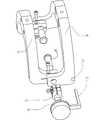
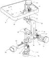
如图1和图2所示,所述微创外科手术机器人主控数据手套,包括手部位置机构L,所述手部位置机构L包括底座39和一四连杆机构;所述底座39内设置有伺服电机,所述底座39上连接有一水平板40和第一电位器49,所述水平板40上固定有一弧形支架41;如图2所示,所述四连杆机构包括顺序铰接的上臂42、上前臂43、下前臂45和下臂44;所述上臂42与所述下臂44之间的铰接轴设置在上述弧形支架41的上端部,所述上臂42端部的第二电位器47和所述下臂端部的第三电位器48通过柔性钢丝与弧形支架41的弧形部分连接,构成类似齿轮啮合的传动关系;所述上前臂43和下前臂45之间的铰接轴上设置有末端接头46。As shown in Fig. 1 and Fig. 2, described minimally invasive surgical robot main control data glove comprises hand position mechanism L, and described hand position mechanism L comprises
如图1所示,本发明微创外科手术机器人主控数据手套中,所述末端接头46上设置有手部控制机构H;所述手部控制机构H包括顺序串联的手臂控制机构A、腕关节控制机构W和手掌P,所述手掌P上并联有拇指控制机构T、食指控制机构F和中指控制机构M;所述手掌P与所述拇指控制机构T、食指控制机构F和中指控制机构M的并联处均设置有关节轴;所述手臂控制机构A和所述腕关节控制机构W上均设置有关节轴20;上述每个关节轴20上均设置有用于获得该关节轴关节动作信息的测量部件。As shown in Figure 1, in the minimally invasive surgical robot master control data glove of the present invention, the end joint 46 is provided with a hand control mechanism H; the hand control mechanism H includes an arm control mechanism A, a wrist Joint control mechanism W and palm P, thumb control mechanism T, index finger control mechanism F and middle finger control mechanism M are connected in parallel on the palm P; the palm P is connected with the thumb control mechanism T, index finger control mechanism F and middle finger control mechanism Joint shafts are provided at the parallel connections of M;
如图3所示,本发明微创外科手术机器人主控数据手套中,如图2所示,所述手臂控制机构A包括与位置控制机构L中的末端接头46连接的连接叉架10;所述连接叉架10的底部固定有手臂环体,所述手臂环体包括配合连接在一起的外环2和内环1,其外环2为定环,内环1为动环,外环2通过螺钉与连接叉架10连接,一定位环3通过螺钉5与内环1连接;所述外环2上方固定一轴套,所述手臂控制机构A的关节轴20通过轴承部件(包括轴承6、12、套筒11、轴承盖4、14、螺钉5、13)与外环(2)连接;所述关节轴20的一端与一关节动作测量部件连接;所述关节轴20另一端设置有传动轮7;所述传动轮7通过柔性钢丝与内环1连接,可以实现类似于齿轮啮合方式的传动关系。所述关节动作测量部件包括电位器16和电位器卡15,所述电位器16通过电位器卡15固定在外环2上,所述电位器16的轴通过联轴器17与关节轴20联接。As shown in Fig. 3, in the minimally invasive surgical robot main control data glove of the present invention, as shown in Fig. 2, the arm control mechanism A includes a
如图4所示,本发明微创外科手术机器人主控数据手套中,所述腕关节控制机构W由腕体I23和腕体II24两端分别通过轴/孔配合连接构成一框架,其中一端的连接处设置有腕部关节轴20,为了与人体腕部形状吻合,所述框架的一侧投影呈弧形。所述腕体II24通过螺钉与外环2连接;如图1所示,腕体I23通过螺钉与手掌P连接,所述关节轴20上设置有关节动作测量部件,所述关节动作测量部件包括电位器16、电位器卡15和防转卡槽19,所述防转卡槽19设置在腕体II24上,所述电位器16的轴通过联轴器17与关节轴20联接,所述电位器16通过电位器卡15与防转卡槽19的配合来固定。As shown in Figure 4, in the minimally invasive surgical robot main control data glove of the present invention, the wrist joint control mechanism W is composed of two ends of the wrist body I23 and the wrist body II24 respectively connected through shafts/holes to form a frame, wherein one end A wrist
如图5所示,本发明微创外科手术机器人主控数据手套中,所述拇指控制机构T包括与手掌P顺序铰接的拇指体I28、拇指体II29、拇指体III31和固定在拇指体III31末端的拇指指套38;各铰接处设置有关节轴20,所述每个关节轴20上均设置有关节动作测量部件,通过该关节动作测量部件获得所述拇指指套38在三维空间中的位置和动作数据。As shown in Figure 5, in the minimally invasive surgical robot master data glove of the present invention, the thumb control mechanism T includes a thumb body I28, a thumb body II29, a thumb body III31 and a thumb body III31 fixed at the end of the thumb body P which are sequentially hinged to the palm P. The
如图6所示,本发明微创外科手术机器人主控数据手套中,所述食指控制机构F包括与手掌P顺序铰接的食指体I32、食指体II33、食指体III4和固定在食指体III4末端的食指指套381;各铰接处设置有关节轴20,所述每个关节轴20上均设置有与关节轴20同轴连接设置的关节动作测量部件,通过该关节动作测量部件获得所述食指指套381在三维空间中的位置和动作数据。As shown in Figure 6, in the minimally invasive surgical robot master control data glove of the present invention, the index finger control mechanism F includes an index finger body I32, an index finger body II33, an index finger body III4 and an index finger body III4 fixed at the end of the palm P. The index finger finger cot 381; each joint is provided with a
如图7所示,本发明微创外科手术机器人主控数据手套中,所述中指控制机构M包括与手掌P顺序铰接的中指体I35、中指体II36、中指体III37和固定在中指体III37末端的中指指套382;各铰接处设置有关节轴,所述每个关节轴上均设置有关节动作测量部件,通过该关节动作测量部件获得所述中指指套382在三维空间中的位置和动作数据。所述关节动作测量部件包括电位器16、电位器卡15和防转块26,所述防转块26固定在相应的指体上,所述电位器16的轴通过联轴器17与关节轴20联接,所述电位器16是通过电位器卡1与防转块26的配合来固定。As shown in Figure 7, in the minimally invasive surgical robot master data glove of the present invention, the middle finger control mechanism M includes a middle finger body I35, a middle finger body II36, a middle finger body III37 and a middle finger body III37 fixed at the end of the middle finger body P sequentially hinged to the palm P. The
综上述所,本发明微创外科手术机器人主控数据手套的关键所在是:在各关节处装有电位器,由此,可测量相应转动关节的角度变化。使用者手部穿过手臂环1,手腕与腕关节控制机构W重合。操作者手臂与手臂控制机构A重合。拇指、食指及中指的前端分别通过指套与主控数据手套的拇指控制机构T、食指控制机构F、中指控制机构M的前端连接。In summary, the key point of the minimally invasive surgical robot master control data glove of the present invention is that a potentiometer is installed at each joint, so that the angle change of the corresponding rotating joint can be measured. The user's hand passes through the
下面说明本发明微创外科手术机器人主控数据手套的动作实施过程。The action implementation process of the minimally invasive surgical robot master data glove of the present invention is described below.
本微创外科手术机器人主控数据手套通过在各关节处装有电位器,用来测量相应转动关节的角度。操作者手部穿过手臂环体,操作者手臂与手臂控制机构A重合,手腕与腕关节控制机构W自然重合。拇指、食指及中指的前端分别通过各指套与主控数据手套的拇指控制机构T、食指控制机构F、中指控制机构M的前端连接。本发明主控数据手套可采集操作者手在空间运动的位置信号和手臂、腕关节、拇指、食指及中指的关节运动信号,用于控制微创外科手术机器人多功能末端工具进行腹腔、胸腔等部位微创外科手术。The minimally invasive surgical robot master control data glove is equipped with potentiometers at each joint to measure the angle of the corresponding rotating joint. The operator's hand passes through the arm ring body, the operator's arm coincides with the arm control mechanism A, and the wrist coincides with the wrist joint control mechanism W naturally. The front ends of the thumb, forefinger and middle finger are respectively connected with the front ends of the thumb control mechanism T, the index finger control mechanism F and the middle finger control mechanism M of the master data glove through the fingertips. The main control data glove of the present invention can collect the position signal of the operator's hand in space and the joint movement signal of the arm, wrist joint, thumb, index finger and middle finger, and is used to control the multifunctional terminal tool of the minimally invasive surgical robot to carry out abdominal cavity, chest cavity, etc. Site minimally invasive surgery.
一、微创外科手术机器人主控数据手套手指关节测量1. Minimally invasive surgical robot master control data glove finger joint measurement
操作者拇指动作时,通过拇指指套38带动拇指体III31及关节轴20相对于拇指体II29转动,关节轴20通过联轴器17带动电位器16的轴转动,电位器卡15通过螺母将电位器16相对于防转块26及拇指体II29固定,拇指体III31相对于拇指体II29的转动转化为电位器16的轴相对于自身的转动,即可由电位器16测量。拇指体III31带动拇指体II29及防转块26相对于拇指体I28转动,电位器卡15通过螺母将电位器16与防转块26及拇指体II29固定,电位器16的轴通过联轴器17与关节轴20及拇指体I28固定,拇指体II29相对于拇指体I28的转动转化为电位器16的轴相对于自身的转动,即可由电位器16测量。拇指体II29带动拇指体I28及该对应位置的关节轴(即:手指基轴)20相对于手掌P转动,电位器16的轴通过联轴器17与手指基轴20连接,电位器卡15通过螺母将电位器16与防转块26及手掌P固定,拇指体I28相对于手掌P的转动可转化为电位器16的轴相对于自身的转动,即可由电位器16测量。即操作者拇指的动作可由拇指控制机构T测量。When the operator’s thumb moves, the thumb body III31 and the
操作者食指动作时,通过食指指套381带动食指体III34及关节轴20相对于食指体II33转动,关节轴20通过联轴器17带动电位器16的轴转动,电位器卡15通过螺母将电位器16相对于防转块26及食指体II33固定,食指体III34相对于食指体II33的转动转化为电位器16的轴相对于自身的转动,即可由电位器16测量。食指体III34带动食指体II33及防转块26相对于食指体I32转动,电位器卡15通过螺母将电位器16与防转块26与食指体II33固定,电位器16的轴通过联轴器18与关节轴20及食指体I32固定,食指体II33相对于食指I32的转动转化为电位器16的轴相对于自身的转动,即可由电位器16测量。食指体II33带动食指体I32及关节轴(手指基轴)20相对于手掌P转动,电位器16的轴通过联轴器17与手指基轴20连接,电位器卡15通过螺母将电位器16与防转块26及手掌P固定,食指体I32相对于手掌P的转动可转化为电位器16的轴相对于自身的转动,即可由电位器16测量。即操作者食指的动作可由食指控制机构F测量。When the operator's index finger moves, the index finger body III34 and the
操作者中指动作时,通过中指指套382带动中指体III37及关节轴20相对于中指体II36转动,关节轴20通过联轴器17带动电位器16的轴转动,电位器卡15通过螺母将电位器16相对于防转块26及中指体II37固定,中指体III37相对于中指体II36的转动转化为电位器16的轴相对于自身的转动,即可由电位器16测量。中指体III37带动中指体II36及防转块26相对于中指体I35转动,电位器卡15通过螺母将电位器16与防转块26及中指体II36固定,电位器16的轴通过联轴器17与关节轴20及中指体I35固定,中指体II36相对于中指体I35的转动转化为电位器16的轴相对于自身的转动,即可由电位器16测量。中指体II36带动中指体I35及关节轴(手指基轴)20相对于手掌P转动,电位器16的轴通过联轴器17与手指基轴20连接,电位器卡15通过螺母将电位器16与防转块26及手掌P固定,中指体I35相对于手掌P的转动可转化为电位器16的轴相对于自身的转动,即可由电位器16测量。及操作者中指的动作可由中指控制机构M测量。When the operator's middle finger moves, the middle finger body III37 and the
二、微创外科手术机器人主控数据手套腕关节动作测量2. Minimally invasive surgical robot master control data glove wrist joint motion measurement
操作者手腕关节转动时,通过数据手套前端拇指机构、食指机构、中指机构及手掌带动腕体I23相对于腕体II24转动;腕体I23通过锁紧机构带动腕部关节轴20转动;腕部关节轴20通过联轴器17带动电位器16的轴转动;电位器卡15通过通过螺母将电位器16相对于腕体II24固定;腕体I23相对于腕体II24的转动转化为电位器16的轴相对于自身的转动,即可测量操作者的手腕的转动动作。When the operator's wrist joint rotates, the thumb mechanism, index finger mechanism, middle finger mechanism and palm at the front of the data glove drive the wrist body I23 to rotate relative to the wrist body II24; the wrist body I23 drives the wrist
三、微创外科手术机器人主控数据手套手臂动作测量3. Minimally invasive surgical robot master control data glove arm movement measurement
操作者手臂自转时,通过数据手套前端拇指机构、食指机构、中指机构及手掌、手腕机构带动手臂环体的内环1相对于外环2转动;手臂环体上缠绕的丝带动传动轮7转动,传动轮7将动力传递给关节轴20,并通过联轴器17带动电位器16的轴转动;电位器卡15通过螺母将电位器16相对于外环2锁紧不可转动;内环1相对于外环2的转动转换为电位器16的轴相对于自身的转动,即可测量操作者手臂的转动动作。When the operator's arm rotates, the
四、微创外科手术机器人主控数据手套手部位置测量4. Minimally invasive surgical robot master control data glove hand position measurement
操作者手部动作时,通过数据手套手部控制机构H带动手部位置机构L的末端接头46在三维空间中运动;末端接头46带动上前臂43、下前臂45运动;上前臂43、下前臂45分别带动上臂42、下臂44绕弧形支架41转动;第二电位器47、第一电位器48分别测量上臂42、下臂44相对于弧形支架41的转动角度;上臂42、下臂44带动弧形支架41及水平板40相对于底座39转动,第一电位器49测量水平板40相对于底座39的转动。由该第一电位器49的测量值和手部位置机构的几何尺寸,通过几何算法可以得出末端接头在三维空间中的位置信息,即可得到操作者的手在三维空间中的位置。When the operator's hand moves, the hand control mechanism H of the data glove drives the
尽管上面结合图对本发明进行了描述,但是本发明并不局限于上述的具体实施方式,上述的具体实施方式仅仅是示意性的,而不是限制性的,本领域的普通技术人员在本发明的启示下,在不脱离本发明宗旨的情况下,还可以作出很多变形,这些均属于本发明的保护之内。Although the present invention has been described above in conjunction with the drawings, the present invention is not limited to the above-mentioned specific embodiments, and the above-mentioned specific embodiments are only illustrative, rather than restrictive. Under the inspiration, many modifications can be made without departing from the gist of the present invention, and these all belong to the protection of the present invention.
Claims (9)
Priority Applications (1)
| Application Number | Priority Date | Filing Date | Title |
|---|---|---|---|
| CN2010100313794ACN101773400B (en) | 2010-01-19 | 2010-01-19 | Minimally invasive surgical robot master control data gloves |
Applications Claiming Priority (1)
| Application Number | Priority Date | Filing Date | Title |
|---|---|---|---|
| CN2010100313794ACN101773400B (en) | 2010-01-19 | 2010-01-19 | Minimally invasive surgical robot master control data gloves |
Publications (2)
| Publication Number | Publication Date |
|---|---|
| CN101773400A CN101773400A (en) | 2010-07-14 |
| CN101773400Btrue CN101773400B (en) | 2011-03-30 |
Family
ID=42510085
Family Applications (1)
| Application Number | Title | Priority Date | Filing Date |
|---|---|---|---|
| CN2010100313794AExpired - Fee RelatedCN101773400B (en) | 2010-01-19 | 2010-01-19 | Minimally invasive surgical robot master control data gloves |
Country Status (1)
| Country | Link |
|---|---|
| CN (1) | CN101773400B (en) |
Families Citing this family (21)
| Publication number | Priority date | Publication date | Assignee | Title |
|---|---|---|---|---|
| CN102773861B (en)* | 2011-05-13 | 2015-01-07 | 苏茂 | Outer frame type data glove |
| CN103158162B (en)* | 2011-12-19 | 2015-09-16 | 苏茂 | External-framework type bidirectional force feedback data glove |
| CN102729238B (en)* | 2012-06-28 | 2014-11-26 | 哈尔滨工程大学 | Three-axis intersection type posture main hand mechanism |
| CN104552340A (en)* | 2013-10-18 | 2015-04-29 | 苏茂 | Arm flexion and extension detecting device |
| CN104552228A (en)* | 2013-10-21 | 2015-04-29 | 苏茂 | Thumb far knuckle joint movement detection device |
| CN104552337A (en)* | 2013-10-21 | 2015-04-29 | 苏茂 | Thumb palm knuckle force feedback detection driving device |
| CN104626193A (en)* | 2013-11-08 | 2015-05-20 | 苏茂 | Little finger joint force feedback device |
| CN104626159A (en)* | 2013-11-08 | 2015-05-20 | 苏茂 | Thumb near-knuckle force feedback detection driving device |
| CN104626203A (en)* | 2013-11-08 | 2015-05-20 | 苏茂 | Straight rod type index finger motion detecting device |
| CN104635911A (en)* | 2013-11-08 | 2015-05-20 | 苏茂 | Thumb far-knuckle force feedback device |
| CN104146772B (en)* | 2014-07-29 | 2016-04-27 | 北京理工大学 | A kind of robot for the accurate diagnosis and treatment of jaw face disease |
| CN104552265A (en)* | 2014-12-23 | 2015-04-29 | 广西大学 | Rotary rocker arm type welding robot |
| CN106078699B (en)* | 2016-08-15 | 2018-06-22 | 黄河科技学院 | The mechanical exoskeleton device of hand decompression |
| CN106361384B (en)* | 2016-08-27 | 2018-09-25 | 天津大学 | A kind of four bar open and close movement devices based on natural cavity |
| CN109091237B (en)* | 2017-06-21 | 2020-08-04 | 山东威高手术机器人有限公司 | Minimally invasive surgical instrument auxiliary system |
| CN107669337A (en)* | 2017-09-26 | 2018-02-09 | 广西南宁栩兮科技有限公司 | A kind of operation robotic manipulation device |
| CN109009453A (en)* | 2018-07-03 | 2018-12-18 | 天津大学 | Intervene the force feedback type main manipulator of robot |
| CN109223432B (en)* | 2018-08-01 | 2021-03-26 | 广州中医药大学(广州中医药研究院) | Intelligent robot for wrist joint rehabilitation |
| CN109620414B (en)* | 2019-01-31 | 2020-12-11 | 刘伟民 | Mechanical gripper force feedback method and system for surgical operation |
| WO2022100480A1 (en)* | 2020-11-10 | 2022-05-19 | 重庆金山医疗机器人有限公司 | Control method for location and orientation of surgical robot end, and control method for surgical robot |
| CN116172722A (en)* | 2023-02-06 | 2023-05-30 | 天津大学 | Force feedback main hand of a minimally invasive surgical robot |
- 2010
- 2010-01-19CNCN2010100313794Apatent/CN101773400B/ennot_activeExpired - Fee Related
Also Published As
| Publication number | Publication date |
|---|---|
| CN101773400A (en) | 2010-07-14 |
Similar Documents
| Publication | Publication Date | Title |
|---|---|---|
| CN101773400B (en) | Minimally invasive surgical robot master control data gloves | |
| CN102499757B (en) | Nine-degree-of-freedom minimally invasive surgical robot main manipulator with force feedback | |
| CN104622585B (en) | A kind of peritoneoscope micro-wound operation robot principal and subordinate's isomorphism main hands of formula remote operating | |
| CN101444431B (en) | Three-dimensional force feedback master manipulator of assisted minimally invasive surgical robot | |
| CN105397838B (en) | Main hand operating wrist of master-slave robot | |
| CN102973321B (en) | Manual multi-degree of freedom micro-manipulator for surgical operation | |
| RU2720830C1 (en) | Assisting surgical complex | |
| CN110934644A (en) | 7-degree-of-freedom series minimally invasive surgery robot main manipulator | |
| CN103128744A (en) | Humanoid flexible mechanical arm device | |
| CN102579227A (en) | Hand and wrist exoskeleton rehabilitation training device | |
| CN103170960A (en) | Human-imitation synchronous wireless control mechanical arm system | |
| CN101947126A (en) | Bone surgery auxiliary robot system | |
| CN110179541A (en) | Robot perceptual system and control method | |
| CN114145964B (en) | Man-machine compatible two-stage parallel type wrist exoskeleton rehabilitation robot | |
| CN106112963A (en) | A kind of Wearable hand ESD | |
| CN203171617U (en) | Humanoid synchronous wireless control mechanical hand system | |
| CN204484326U (en) | The main hands of a kind of peritoneoscope micro-wound operation robot principal and subordinate's isomorphism formula remote operating | |
| CN211512046U (en) | 7-degree-of-freedom series minimally invasive surgery robot main manipulator | |
| CN203680324U (en) | Outer framework wearing-type data glove | |
| CN114711760B (en) | A Calculation Method of Joint Axis | |
| Fu et al. | Development of a multi-DOF exoskeleton based machine for injured fingers | |
| Zhu et al. | Underactuated rehabilitation robotics for hand function | |
| US20200297447A1 (en) | A device for sensing the pose and motion of a human's arm-hand | |
| CN117100407A (en) | Opening and closing input device, rotary input device, force feedback master hand and surgical robot | |
| Xue et al. | Ergonomics-based design of handheld concentric tube robot |
Legal Events
| Date | Code | Title | Description |
|---|---|---|---|
| C06 | Publication | ||
| PB01 | Publication | ||
| C10 | Entry into substantive examination | ||
| SE01 | Entry into force of request for substantive examination | ||
| C14 | Grant of patent or utility model | ||
| GR01 | Patent grant | ||
| C17 | Cessation of patent right | ||
| CF01 | Termination of patent right due to non-payment of annual fee | Granted publication date:20110330 Termination date:20120119 |