CN101772287A - Electronic device with sliding closure function - Google Patents
Electronic device with sliding closure functionDownload PDFInfo
- Publication number
- CN101772287A CN101772287ACN200910312752ACN200910312752ACN101772287ACN 101772287 ACN101772287 ACN 101772287ACN 200910312752 ACN200910312752 ACN 200910312752ACN 200910312752 ACN200910312752 ACN 200910312752ACN 101772287 ACN101772287 ACN 101772287A
- Authority
- CN
- China
- Prior art keywords
- slide bar
- sliding
- sliding closure
- electronic equipment
- support
- Prior art date
- Legal status (The legal status is an assumption and is not a legal conclusion. Google has not performed a legal analysis and makes no representation as to the accuracy of the status listed.)
- Granted
Links
Images


Classifications
- G—PHYSICS
- G06—COMPUTING OR CALCULATING; COUNTING
- G06F—ELECTRIC DIGITAL DATA PROCESSING
- G06F1/00—Details not covered by groups G06F3/00 - G06F13/00 and G06F21/00
- G06F1/16—Constructional details or arrangements
- G06F1/1613—Constructional details or arrangements for portable computers
- G06F1/1615—Constructional details or arrangements for portable computers with several enclosures having relative motions, each enclosure supporting at least one I/O or computing function
- G06F1/1624—Constructional details or arrangements for portable computers with several enclosures having relative motions, each enclosure supporting at least one I/O or computing function with sliding enclosures, e.g. sliding keyboard or display
- G—PHYSICS
- G06—COMPUTING OR CALCULATING; COUNTING
- G06F—ELECTRIC DIGITAL DATA PROCESSING
- G06F1/00—Details not covered by groups G06F3/00 - G06F13/00 and G06F21/00
- G06F1/16—Constructional details or arrangements
- G06F1/1613—Constructional details or arrangements for portable computers
- G06F1/1615—Constructional details or arrangements for portable computers with several enclosures having relative motions, each enclosure supporting at least one I/O or computing function
- G06F1/1616—Constructional details or arrangements for portable computers with several enclosures having relative motions, each enclosure supporting at least one I/O or computing function with folding flat displays, e.g. laptop computers or notebooks having a clamshell configuration, with body parts pivoting to an open position around an axis parallel to the plane they define in closed position
- G—PHYSICS
- G06—COMPUTING OR CALCULATING; COUNTING
- G06F—ELECTRIC DIGITAL DATA PROCESSING
- G06F1/00—Details not covered by groups G06F3/00 - G06F13/00 and G06F21/00
- G06F1/16—Constructional details or arrangements
- G06F1/1613—Constructional details or arrangements for portable computers
- G06F1/1633—Constructional details or arrangements of portable computers not specific to the type of enclosures covered by groups G06F1/1615 - G06F1/1626
- G06F1/1675—Miscellaneous details related to the relative movement between the different enclosures or enclosure parts
- G06F1/1679—Miscellaneous details related to the relative movement between the different enclosures or enclosure parts for locking or maintaining the movable parts of the enclosure in a fixed position, e.g. latching mechanism at the edge of the display in a laptop or for the screen protective cover of a PDA
Landscapes
- Engineering & Computer Science (AREA)
- Theoretical Computer Science (AREA)
- Computer Hardware Design (AREA)
- Physics & Mathematics (AREA)
- Human Computer Interaction (AREA)
- General Engineering & Computer Science (AREA)
- General Physics & Mathematics (AREA)
- Mathematical Physics (AREA)
- Casings For Electric Apparatus (AREA)
- Telephone Set Structure (AREA)
Abstract
Translated fromChinese
Description
Translated fromChinese技术领域technical field
本发明涉及一种具有滑盖功能的电子设备,尤其涉及一种盖体可滑开后旋转的电子设备。The invention relates to an electronic device with a sliding cover function, in particular to an electronic device whose cover body can be slid open and then rotated.
背景技术Background technique
电子设备如手机、笔记本电脑等通常具有翻盖式和滑盖式两种结构,滑盖式结构的特点在于:由两大部分组成,即本体和相对本体滑动的盖体,显示屏设置于盖体上,而按键则设置在本体上。未使用时,盖体遮住本体上的键盘;使用时推动盖体,盖体在本体上滑动并露出按键供用户使用。滑盖式结构在缩小手机体积的同时,能够使手机外观更加时尚。Electronic devices such as mobile phones and notebook computers usually have two structures: clamshell and slide. The feature of the slide structure is that it consists of two parts, namely the body and the cover that slides relative to the body. The display screen is set on the cover. , while the buttons are set on the body. When not in use, the cover body covers the keyboard on the body; when in use, the cover body is pushed, and the cover body slides on the body to expose keys for users to use. The sliding cover structure can make the appearance of the mobile phone more fashionable while reducing the volume of the mobile phone.
然而,翻盖结构可以任意调整盖体与本体之间的角度,进而使得显示屏处于最佳的观看使用角度,滑盖机构并不具有该优点。因此,在同一电子设备上实现翻盖和滑盖是目前所面临的问题。However, the flip structure can adjust the angle between the cover body and the body arbitrarily, so that the display screen is at an optimal viewing angle, and the slide cover mechanism does not have this advantage. Therefore, realizing flip cover and slide cover on the same electronic device is a problem faced at present.
发明内容Contents of the invention
有鉴于此,有必要提供一种同时实现滑盖和翻盖双功能的电子设备。In view of this, it is necessary to provide an electronic device that simultaneously realizes the dual functions of a sliding cover and a flip cover.
本发明提供一种具有滑盖功能的电子设备,该电子设备包括本体、盖体和滑动连接本体和盖体的滑盖机构,所述本体上开设有滑动槽,所述滑动槽底部设置有多个连续的定位槽,所述滑盖机构包括第一支架和第二支架,所述第一支架和第二支架一端彼此转动连接,另一端设置于滑动槽内并能在不同的定位槽上固定。The invention provides an electronic device with a sliding cover function. The electronic device includes a main body, a cover body and a sliding cover mechanism for slidably connecting the main body and the cover body. A continuous positioning slot, the sliding cover mechanism includes a first bracket and a second bracket, one end of the first bracket and the second bracket is connected to each other in rotation, the other end is arranged in the sliding slot and can be fixed on different positioning slots .
本发明电子设备能够实现盖体滑开后并旋转,露出按键的同时任意调整盖体与本体之间的角度,具有滑盖结构的优点和翻盖结构带来的视觉角度效果。The electronic device of the present invention can slide and rotate the cover body to expose the keys while arbitrarily adjusting the angle between the cover body and the body, and has the advantages of the sliding cover structure and the visual angle effect brought by the flip cover structure.
附图说明Description of drawings
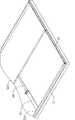
图1为一较佳实施方式电子设备的立体图。FIG. 1 is a perspective view of an electronic device in a preferred embodiment.
图2为图1所示电子设备的爆炸图。FIG. 2 is an exploded view of the electronic device shown in FIG. 1 .
图3为图1所示III-III方向上的剖视图。Fig. 3 is a sectional view along the direction III-III shown in Fig. 1 .
图4为图3所示部分IV的放大图。FIG. 4 is an enlarged view of part IV shown in FIG. 3 .
图5为图1所示电子设备盖体闭合的示意图。FIG. 5 is a schematic diagram of closing the cover of the electronic device shown in FIG. 1 .
图6为图1所示电子设备盖体滑开的示意图。FIG. 6 is a schematic diagram of the cover of the electronic device shown in FIG. 1 sliding open.
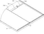
图7为图1所示电子设备盖体旋转的示意图。FIG. 7 is a schematic diagram of the rotation of the cover of the electronic device shown in FIG. 1 .
主要元件符号说明Description of main component symbols
具体实施方式Detailed ways
请参阅图1,为一较佳实施方式电子设备100的立体图。电子设备100包括本体10、盖体20、设置于本体10表面的按键30和设置于盖体20表面的显示屏40(参考图2),盖体20可相对本体10滑开后旋转,使得用户使用按键30的同时可任意调整用户观看显示屏40的角度。在本实施方式当中,电子设备100为一笔记本型电脑。Please refer to FIG. 1 , which is a perspective view of an
请一并参阅图2和图3,其中图2为图1所示电子设备100的爆炸图,图3为图1III-III所示方向上的剖视图。本体10包括两相互卡合固定的上壳体11、下壳体12。上壳体11和下壳体12为长方形壳体形状,其共同形成一空间,用于容置实现其功能的电子组件(图中未示)。上壳体11中间平行盖体20滑开方向上开设一长条形的通槽13,上壳体11、下壳体12卡合处形成平行上述通槽13的两滑动槽14,每一滑动槽14的底边上形成有若干连续的定位槽15。Please refer to FIG. 2 and FIG. 3 together, wherein FIG. 2 is an exploded view of the
电子设备100还包括滑动连接本体10和盖体20的滑盖机构50。滑盖机构50包括第一支架51和第二支架52,所述第一支架51和第二支架52一端彼此转动连接。另一端设置于滑动槽14内并能在不同的定位槽15上固定。The
第一支架51包括两端设置于上述定位槽14内的第一滑杆511和自第一滑杆511中间位置垂直延伸的第一转杆512。其中,第一滑杆511两端为半圆形,其设置于滑动槽14内并能在不同的定位槽15内固定。第一转杆512为可穿过上述通槽13的“L”形板件,远离第一滑杆511的一端上开设有两平行的枢轴孔513和514,其分别用于与盖体20和第二支架52转动连接。The
盖体20使用一枢轴转动固定于上述枢轴孔514内,枢轴可为大多数笔记本电脑、手机使用的枢轴,其使得盖体20可相对第一支架51有摩擦地转动并可停留在任一角度。The
第二支架52与上述第一支架51形状相同,其相应包括第二滑杆521、第二转杆522和开设于第二转杆522上的枢轴孔523,第二滑杆521设置于上述滑动槽14内,第二转杆522穿过通槽13后,枢轴依次穿过枢轴孔513和523使得第一支架51和第二支架52转动连接。在本实施方式当中,第一转杆512和第二转杆522的长度之和小于定位槽15的长度之和,使得盖体20需相对本体10平行滑开一段距离后才能旋转。The
请参阅图4,为图3所示部分IV的放大图。滑盖机构50还包括设置于第一滑杆511、第二滑杆521与定位槽15之间的弧形弹片53和弹性件54,弹片53贴合与上述不同定位槽15内,弹性件54两端分别与弹片53和第一滑杆511和第二转杆521的两端接触。当无外力作用盖体20、第一转杆512或第二转杆522时,弹片53受弹性件54作用贴合任意定位槽15内并使得第一滑杆511或第二滑杆521固定于该定位槽15上;当有外力作用盖体20、第一转杆512或第二转杆522时,弹性件54被压缩并能在滑动槽14内滑动,直至无外力作用时,第一滑杆511或第二滑杆521重新固定于另一定位槽15上。在本实施方式当中,弹性件54为一喇叭螺旋状弹簧,其小径端固定于第一滑杆511或第二滑杆521上,大径端与弹片53接触。Please refer to FIG. 4 , which is an enlarged view of part IV shown in FIG. 3 . The
请参阅图5,为电子设备100的盖体20闭合的示意图。此时,第一支架51固定于最前端的定位槽15内,转动固定于第一支架51上的盖体20平行遮住设置于本体10上的按键30。如图5中向前推盖体20,第一支架51和第二支架52将沿着滑动槽14同步滑至图6所示状态。Please refer to FIG. 5 , which is a schematic diagram of closing the
请参阅图6,为电子设备100的盖体20滑开的示意图。此状态下第二支架52固定于滑动槽14末端的定位槽15内,盖体20相对本体10平行滑开并露出部分按键30可供用户使用。继续向前推动盖体20,第二滑杆521定位于该末端的定位槽15内,第一滑杆511将沿着滑动槽14运动,同时第一转杆512和第二转杆522相对转动至图7所示状态。Please refer to FIG. 6 , which is a schematic diagram of the
请参阅图7,为电子设备100的盖体20滑开后旋转的示意图。固定于第一支架51上的盖体20相对本体10继续滑开并旋转,露出全部按键30供用户使用。同时,用户调整盖体20相对第一支架10的角度,使其上的显示屏40处于最佳的观看使用角度。Please refer to FIG. 7 , which is a schematic diagram of the
Claims (9)
Priority Applications (2)
| Application Number | Priority Date | Filing Date | Title |
|---|---|---|---|
| CN2009103127520ACN101772287B (en) | 2009-12-30 | 2009-12-30 | Electronic device with slide function |
| US12/940,037US20110157793A1 (en) | 2009-12-30 | 2010-11-04 | Slide-type electronic device |
Applications Claiming Priority (1)
| Application Number | Priority Date | Filing Date | Title |
|---|---|---|---|
| CN2009103127520ACN101772287B (en) | 2009-12-30 | 2009-12-30 | Electronic device with slide function |
Publications (2)
| Publication Number | Publication Date |
|---|---|
| CN101772287Atrue CN101772287A (en) | 2010-07-07 |
| CN101772287B CN101772287B (en) | 2012-03-28 |
Family
ID=42504741
Family Applications (1)
| Application Number | Title | Priority Date | Filing Date |
|---|---|---|---|
| CN2009103127520AExpired - Fee RelatedCN101772287B (en) | 2009-12-30 | 2009-12-30 | Electronic device with slide function |
Country Status (2)
| Country | Link |
|---|---|
| US (1) | US20110157793A1 (en) |
| CN (1) | CN101772287B (en) |
Cited By (3)
| Publication number | Priority date | Publication date | Assignee | Title |
|---|---|---|---|---|
| CN103076844A (en)* | 2011-10-26 | 2013-05-01 | 纬创资通股份有限公司 | Slider Electronics |
| CN103298293A (en)* | 2012-02-29 | 2013-09-11 | 元镫金属股份有限公司 | Opening stabilization device for flip-type electronic products |
| TWI487467B (en)* | 2012-01-09 | 2015-06-01 | Wistron Corp | Hinge assembly having linear movement and slide type electronic device |
Families Citing this family (2)
| Publication number | Priority date | Publication date | Assignee | Title |
|---|---|---|---|---|
| CN103135674B (en)* | 2011-11-29 | 2016-05-25 | 英业达股份有限公司 | electronic device |
| CN104679318B (en)* | 2013-11-29 | 2017-10-17 | 英业达科技有限公司 | Electronic installation |
Family Cites Families (39)
| Publication number | Priority date | Publication date | Assignee | Title |
|---|---|---|---|---|
| US1203659A (en)* | 1914-05-08 | 1916-11-07 | Underwood Typewriter Co | Copy-holder. |
| US2374409A (en)* | 1944-04-21 | 1945-04-24 | Gallagher Ellen | Bookstand |
| US4440373A (en)* | 1981-02-17 | 1984-04-03 | Bruce Beitler | Folio and notebook display stand |
| US5035393A (en)* | 1990-03-12 | 1991-07-30 | Menaged David L | Portable, collapsible reading stand with adjustment means |
| US5168426A (en)* | 1991-08-16 | 1992-12-01 | Beaver Computer Corporation | Hinge mechanism for cover panel of portable computer including slide mechanism |
| US5290002A (en)* | 1992-09-30 | 1994-03-01 | Cohen Dell P | Adjustable reading and writing aid system |
| KR960007178Y1 (en)* | 1994-06-28 | 1996-08-22 | 양시경 | A reading rack |
| US5552957A (en)* | 1994-09-09 | 1996-09-03 | International Business Machines Corporation | Portable computer field kit |
| JP3011988U (en)* | 1994-12-02 | 1995-06-06 | 株式会社ニチエイ | Frame holder |
| US5810316A (en)* | 1996-11-06 | 1998-09-22 | Eby; Thomas L. | Adjustable and collapsible book stand |
| US6045108A (en)* | 1998-11-30 | 2000-04-04 | Binney & Smith Inc. | Inclined adjustable easel with slidably drawer |
| US7104516B2 (en)* | 2001-01-10 | 2006-09-12 | Kabushiki Kaisha Toshiba | Electronic equipment mounting angle varying apparatus |
| US6679468B1 (en)* | 2001-03-06 | 2004-01-20 | Kuo-Liang Hsu | Pen box structure having the function of a book support shelf |
| US6480373B1 (en)* | 2001-07-24 | 2002-11-12 | Compaq Information Technologies Group, L.P. | Multifunctional foldable computer |
| US6636419B2 (en)* | 2001-08-09 | 2003-10-21 | Danger, Inc. | Handheld display and keyboard |
| WO2003021408A2 (en)* | 2001-08-29 | 2003-03-13 | Danger, Inc. | Sliding display apparatus |
| TW545858U (en)* | 2002-11-22 | 2003-08-01 | Compal Electronics Inc | Portable electronic device having a lid with an additional supporting function |
| US6816365B2 (en)* | 2003-01-28 | 2004-11-09 | International Business Machines Corporation | Laptop display screen and keyboard mounting structure |
| US6882524B2 (en)* | 2003-04-25 | 2005-04-19 | Motion Computing, Inc. | Combined modular keyboard and tablet PC protective cover |
| US7298610B2 (en)* | 2003-08-01 | 2007-11-20 | Lg Electronics Inc. | Supporting apparatus for portable computer |
| TWI221954B (en)* | 2003-08-07 | 2004-10-11 | Benq Corp | Flat panel display |
| TWM245468U (en)* | 2003-10-02 | 2004-10-01 | Tatung Co | Automatically buckled supporting frame structure |
| TWM246646U (en)* | 2003-11-14 | 2004-10-11 | Tatung Co | Notebook computer having hanging-type monitor |
| TWM249084U (en)* | 2003-12-31 | 2004-11-01 | Tatung Co | Support structure for portable computer |
| US7187538B2 (en)* | 2004-04-07 | 2007-03-06 | Hewlett-Packard Development Company, L.P. | Hinge for electronic device |
| TWM262639U (en)* | 2004-08-31 | 2005-04-21 | Tatung Co | Adjustable supporting structure of flat panel computer |
| KR100586979B1 (en)* | 2004-09-02 | 2006-06-08 | 삼성전기주식회사 | Automatic / Manual Slide Communication Terminal |
| US7239505B2 (en)* | 2004-10-08 | 2007-07-03 | Microsoft Corporation | Direct hinge for optimizing conversion |
| US7184263B1 (en)* | 2005-08-04 | 2007-02-27 | Acer Inc. | Portable computer |
| CN1941793B (en)* | 2005-09-30 | 2010-05-05 | 鸿富锦精密工业(深圳)有限公司 | Portable electronic device with camera head |
| KR101237560B1 (en)* | 2006-02-17 | 2013-02-26 | 엘지전자 주식회사 | Stand of a display device |
| TWI296883B (en)* | 2006-03-17 | 2008-05-11 | Htc Corp | Portable electronic device |
| KR100713480B1 (en)* | 2006-03-22 | 2007-05-02 | 삼성전자주식회사 | Hinge device of a portable terminal |
| US7828260B2 (en)* | 2006-03-23 | 2010-11-09 | Hauser Stephen G | Deployable support unit for reading material |
| US20080062624A1 (en)* | 2006-09-13 | 2008-03-13 | Paul Regen | Transformable Mobile Computing Device |
| JP4669561B2 (en)* | 2007-03-16 | 2011-04-13 | 富士通株式会社 | Stand and electronics system |
| TWI329252B (en)* | 2007-06-01 | 2010-08-21 | Asustek Comp Inc | Portable electronic device |
| US7925310B2 (en)* | 2007-06-05 | 2011-04-12 | Accton Technology Corporation | Communication device with stickup structure |
| TW200848983A (en)* | 2007-06-05 | 2008-12-16 | Asustek Comp Inc | Portable electronic device |
- 2009
- 2009-12-30CNCN2009103127520Apatent/CN101772287B/ennot_activeExpired - Fee Related
- 2010
- 2010-11-04USUS12/940,037patent/US20110157793A1/ennot_activeAbandoned
Cited By (5)
| Publication number | Priority date | Publication date | Assignee | Title |
|---|---|---|---|---|
| CN103076844A (en)* | 2011-10-26 | 2013-05-01 | 纬创资通股份有限公司 | Slider Electronics |
| CN103076844B (en)* | 2011-10-26 | 2015-10-28 | 纬创资通股份有限公司 | Sliding cover type electronic device |
| TWI487467B (en)* | 2012-01-09 | 2015-06-01 | Wistron Corp | Hinge assembly having linear movement and slide type electronic device |
| CN103298293A (en)* | 2012-02-29 | 2013-09-11 | 元镫金属股份有限公司 | Opening stabilization device for flip-type electronic products |
| CN103298293B (en)* | 2012-02-29 | 2016-04-06 | 元镫金属股份有限公司 | Opening stabilization device for flip-type electronic products |
Also Published As
| Publication number | Publication date |
|---|---|
| CN101772287B (en) | 2012-03-28 |
| US20110157793A1 (en) | 2011-06-30 |
Similar Documents
| Publication | Publication Date | Title |
|---|---|---|
| US7522944B2 (en) | Portable communication apparatus | |
| CN201805647U (en) | Portable communication device and its supporting device | |
| EP1806909B1 (en) | Portable communication terminal for games and user interfacing device thereof | |
| US20050245297A1 (en) | Portable communication device with sliding and pop-up type keypads | |
| US8108016B2 (en) | Portable communication device having a dual sliding flip hinge assembly | |
| US20120257368A1 (en) | Extendable connecting link | |
| US7752712B2 (en) | Hinge | |
| US20100144408A1 (en) | Handheld electronic device | |
| CN1964374A (en) | Mobile terminal with a sliding cradle and the sliding cradle thereof | |
| US20060225249A1 (en) | Swing hinge device for mobile terminal | |
| CN101631441A (en) | Portable terminal | |
| US20100016038A1 (en) | Portable communication device having an open channel hinge assembly | |
| EP1901532A2 (en) | Flip-up type mobile phone | |
| CN102573366A (en) | Electronic device | |
| TWI437412B (en) | Portable electronic apparatus | |
| CN101772287A (en) | Electronic device with sliding closure function | |
| TW201128355A (en) | Slide-type electronic device | |
| CN101990752B (en) | Portable communication device having a combined slider and flip hinge assembly | |
| US8478368B2 (en) | Portable electronic device | |
| US20120293927A1 (en) | Sliding module for electronic device | |
| US20100011538A1 (en) | Portable communication device having a multi-axis hinge assembly | |
| JP5733311B2 (en) | Slide mechanism and portable device | |
| TWI388264B (en) | Portable electronic device | |
| CN102752977A (en) | Combination of electronic device | |
| CN101344796A (en) | Sliding device |
Legal Events
| Date | Code | Title | Description |
|---|---|---|---|
| C06 | Publication | ||
| PB01 | Publication | ||
| C10 | Entry into substantive examination | ||
| SE01 | Entry into force of request for substantive examination | ||
| C14 | Grant of patent or utility model | ||
| GR01 | Patent grant | ||
| C17 | Cessation of patent right | ||
| CF01 | Termination of patent right due to non-payment of annual fee | Granted publication date:20120328 Termination date:20131230 |