CN101767065B - Door open-close mechanism and hanging basket adjusting mechanism for blood centrifugal machine - Google Patents
Door open-close mechanism and hanging basket adjusting mechanism for blood centrifugal machineDownload PDFInfo
- Publication number
- CN101767065B CN101767065BCN2010101022160ACN201010102216ACN101767065BCN 101767065 BCN101767065 BCN 101767065BCN 2010101022160 ACN2010101022160 ACN 2010101022160ACN 201010102216 ACN201010102216 ACN 201010102216ACN 101767065 BCN101767065 BCN 101767065B
- Authority
- CN
- China
- Prior art keywords
- optocoupler
- hanging basket
- motor
- fixed
- upper cover
- Prior art date
- Legal status (The legal status is an assumption and is not a legal conclusion. Google has not performed a legal analysis and makes no representation as to the accuracy of the status listed.)
- Active
Links
- 239000008280bloodSubstances0.000titleclaimsabstractdescription26
- 210000004369bloodAnatomy0.000titleclaimsabstractdescription26
- 125000006850spacer groupChemical group0.000claimsdescription11
- 230000000903blocking effectEffects0.000claimsdescription3
- 230000003287optical effectEffects0.000claims1
- 230000003068static effectEffects0.000abstractdescription3
- 244000309464bullSpecies0.000description6
- 239000000306componentSubstances0.000description5
- 238000000034methodMethods0.000description4
- 230000005540biological transmissionEffects0.000description3
- 238000000926separation methodMethods0.000description2
- 239000012503blood componentSubstances0.000description1
- 238000001125extrusionMethods0.000description1
Images

Landscapes
- Centrifugal Separators (AREA)
Abstract
Translated fromChinese
Description
Translated fromChinese技术领域technical field
本发明涉及一种离心分离设备,具体涉及一种具有自动开关门机构及吊篮调整机构的组件的血液离心机。The invention relates to a centrifugal separation device, in particular to a blood centrifuge with components of an automatic door opening mechanism and a hanging basket adjustment mechanism.
技术背景technical background
血液成份的分离一般在血液离心机中进行,目前国内血液离心机多为手工抓取血型卡,这样就需要采用手动翻盖式开门机构,同时由于采用手动抓取方式,就不需要对吊篮的角度进行严格要求,所以在吊篮静态时就可手动取卡。但全自动血型分析仪的使用的离心机要求为无人工全自动操作系统,就不能使用手动翻盖式开门机构,同时抓取血型卡均为机械手进行,所以对吊篮倾斜角度进行要求。所以目前市场上现有的离心机不能满足全自动开门及对吊篮角度调整的要求。The separation of blood components is generally carried out in a blood centrifuge. At present, most blood centrifuges in China use manual capture of the blood type card, which requires a manual flip-type door opening mechanism. The angle is strictly required, so the card can be manually removed when the hanging basket is static. However, the centrifuge used by the automatic blood type analyzer is required to be a fully automatic operating system without manual operation, so the manual flip-type door opening mechanism cannot be used. At the same time, the blood type card is captured by the robot, so the tilt angle of the hanging basket is required. Therefore, the existing centrifuges on the market cannot meet the requirements of fully automatic door opening and angle adjustment of the hanging basket.
发明内容Contents of the invention
本发明主要解决的技术问题是提供一种具有自动开关门机构及吊篮调整机构的组件的血液离心机,在工作过程中可以实现自动控制开关门及对吊篮倾斜角度的调整要求,这样可以实现全程自动化控制,同时为机械手的抓取血型卡提供精准的角度位置要求。The main technical problem to be solved by the present invention is to provide a blood centrifuge with components of an automatic door opening mechanism and a hanging basket adjustment mechanism, which can automatically control the opening and closing of the door and the adjustment requirements for the inclination angle of the hanging basket during the working process, so that Realize the whole process of automatic control, and at the same time provide precise angular position requirements for the manipulator to grab the blood type card.
为了解决上述技术问题,本发明的一种具有自动开关门机构及吊篮调整机构的组件的血液离心机包括离心机本体以及设置于所述血液离心机的机壳上的一上盖和设置于所述离心机本体上的吊篮,还包括开关门装置,所述开关门装置与所述上盖连接,所述开关门装置与所述上盖上分别设有位置相对应的空洞。In order to solve the above technical problems, a blood centrifuge with an automatic door opening mechanism and a hanging basket adjustment mechanism of the present invention includes a centrifuge body and an upper cover set on the casing of the blood centrifuge and a The hanging basket on the centrifuge body also includes a door opening and closing device connected to the upper cover, and the opening and closing device and the upper cover are respectively provided with corresponding cavities.
所述开关门装置包括大齿轮、小齿轮、销、电机座、步进电机、固定轴承座、轴承、旋转轴承座、隔套、压板和锁紧螺母.步进电机轴与小齿轮通过销连接,固定在电机座下方,电机座的上方与上盖的底部固定,固定轴承座固定在上盖的底部中心处,其内壁与轴承的外圈紧密接触固定,轴承内圈与旋转轴承座的外壁紧密接触相对固定、可一起相对外圈旋转,压板压紧轴承的外圈,固定在固定轴承座的底部,隔套上端压紧轴承的内圈,下端靠紧大齿轮的顶部,锁紧螺母通过与旋转轴承座的螺纹连接,将大齿轮固定在隔套的下端面,第一光耦安装在电机座靠近大齿轮一侧,光耦挡片安装在大齿轮的底部。大齿轮和小齿轮形成齿轮啮合传动。The door opening and closing device includes a large gear, a pinion, a pin, a motor seat, a stepping motor, a fixed bearing seat, a bearing, a rotating bearing seat, a spacer, a pressure plate and a lock nut. The stepping motor shaft and the pinion are connected by a pin , fixed under the motor seat, the top of the motor seat is fixed with the bottom of the upper cover, the fixed bearing seat is fixed at the bottom center of the upper cover, its inner wall is in close contact with the outer ring of the bearing, and the inner ring of the bearing is in contact with the outer wall of the rotating bearing seat The tight contact is relatively fixed and can rotate together relative to the outer ring. The pressure plate presses the outer ring of the bearing and is fixed at the bottom of the fixed bearing seat. The upper end of the spacer presses the inner ring of the bearing, and the lower end is close to the top of the large gear. The lock nut passes through The threaded connection with the rotating bearing seat fixes the big gear on the lower end surface of the spacer, the first optocoupler is installed on the side of the motor seat close to the big gear, and the optocoupler blocking plate is installed on the bottom of the big gear. The bull gear and the pinion form a gear mesh transmission.
所述开关门装置的空洞位于所述大齿轮上。The cavity of the door opening and closing device is located on the bull gear.
本发明的具有自动开关门机构及吊篮调整机构的组件的血液离心机还包括与所述吊篮连接的吊篮调整机构,吊篮调整机构,包括调整螺母、调整丝杠、导轨、圆柱销、电机,底板。电机固定在底板的底部,调整丝杠通过圆柱销与电机伸出轴连接,调整螺母与调整丝杠相配合,导轨底下端面与底板顶部连接,上侧导轨面与调整螺母相配合,第二光耦安装在导轨的上部侧面,第三光耦安装在导轨的下部侧面,与第二光耦同侧,光耦挡片安装在调整螺母下部,与第二光耦、第三光耦同侧。调整螺母与调整丝杠形成螺纹传动。The blood centrifuge with the assembly of the automatic door opening mechanism and the hanging basket adjustment mechanism of the present invention also includes a hanging basket adjustment mechanism connected with the hanging basket, and the hanging basket adjustment mechanism includes an adjustment nut, an adjustment screw, a guide rail, and a cylindrical pin. , motor, bottom plate. The motor is fixed on the bottom of the bottom plate, the adjusting screw is connected with the extension shaft of the motor through a cylindrical pin, the adjusting nut is matched with the adjusting screw, the bottom surface of the guide rail is connected with the top of the bottom plate, the upper guide rail surface is matched with the adjusting nut, and the second light The coupler is installed on the upper side of the guide rail, the third optocoupler is installed on the lower side of the guide rail, on the same side as the second optocoupler, and the optocoupler block is installed on the lower part of the adjustment nut, on the same side as the second optocoupler and the third optocoupler. The adjusting nut and the adjusting lead screw form a screw drive.
采用本发明的具有自动开关门机构及吊篮调整机构的组件的血液离心机,可以实现自动控制门的开关状态,不用手工进行翻盖开关门,方便、安全、快捷。同时可以对吊篮的倾斜角度进行控制调整,满足机械手对吊篮倾斜角度的要求。Adopting the blood centrifuge with the components of the automatic door opening mechanism and the hanging basket adjustment mechanism of the present invention can realize the automatic control of the opening and closing state of the door, without manual opening and closing of the door, which is convenient, safe and fast. At the same time, the inclination angle of the hanging basket can be controlled and adjusted to meet the requirements of the manipulator for the inclination angle of the hanging basket.
附图说明Description of drawings
下面结合附图和具体实施方式对本发明做进一步详细说明。The present invention will be described in further detail below in conjunction with the accompanying drawings and specific embodiments.
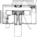
图1为本发明的一种具有自动开关门机构及吊篮调整机构的组件的血液离心机的剖视图。Fig. 1 is a cross-sectional view of a blood centrifuge with components of an automatic door opening mechanism and a hanging basket adjustment mechanism according to the present invention.
图2为本发明的一种具有自动开关门机构及吊篮调整机构的组件的血液离心机的俯视图。Fig. 2 is a top view of a blood centrifuge with components of an automatic door opening mechanism and a hanging basket adjustment mechanism according to the present invention.
具体实施方式Detailed ways
如图1所示,本发明的具有自动开关门机构及吊篮调整机构的组件的血液离心机包括离心机本体1以及设置于所述血液离心机的机壳2上的一上盖11和设置于所述离心机本体1上的吊篮51,还包括开关门装置,开关门装置与上盖11连接,开关门装置与上盖11上分别设有位置相对应的空洞。As shown in FIG. 1 , the blood centrifuge of the present invention, which has an automatic door opening mechanism and a hanging basket adjustment mechanism, includes a centrifuge body 1 and an
开关门装置包括大齿轮21、小齿轮22、销23、电机座24、步进电机25、固定轴承座31、轴承32、旋转轴承座33、隔套34、压板35和锁紧螺母36第一光耦26、光耦挡片12,步进电机25轴与小齿轮22通过销23连接,固定在电机座24下方,电机座24的上方与上盖11的底部固定,固定轴承座31固定在上盖11的底部中心处,其内壁与轴承32的外圈紧密接触,轴承32内圈与旋转轴承座33的外壁紧密接触相对固定、可一起相对外圈旋转,压板35压紧轴承32的外圈,固定在固定轴承座31的底部,隔套34上端压紧轴承32的内圈,下端靠紧大齿轮21的顶部,锁紧螺母36通过与旋转轴承座33的螺纹连接,将大齿轮21固定在隔套34的下端面,第一光耦26安装在电机座24靠近大齿轮21一侧,光耦挡片12安装在大齿轮21的底部。开关门装置的空洞位于大齿轮21上。The opening and closing device includes a
本发明的一种具有自动开关门机构及吊篮调整机构的组件的血液离心机还包括一与吊篮51连接的吊篮调整机构,吊篮调整机构包括调整螺母52、调整丝杠53、导轨54、圆柱销55、电机56、底板60、第二光耦57、第三光耦58、光耦挡片59,电机56固定在底板60的底部,调整丝杠53通过圆柱销55与电机56伸出轴连接,调整螺母52与调整丝杠53相配合,导轨54底下端面与底板60顶部连接,上侧导轨面与调整螺母52相配合,第二光耦57安装在导轨54的上部侧面,第三光耦58安装在导轨54的下部侧面,与第二光耦57同侧,光耦挡片59安装在调整螺母52下部,与第二光耦57、第三光耦58同侧。A blood centrifuge with an automatic door opening mechanism and a hanging basket adjustment mechanism of the present invention also includes a hanging basket adjustment mechanism connected to the hanging
本发明的具有自动开关门机构及吊篮调整机构的组件的血液离心机工作时包括如下工作步骤,首先实现全自动开关门:向步进电机25通电,步进电机25通过销23带动小齿轮22转动,小齿轮22与大齿轮21形成齿轮啮合传动,大齿轮21在隔套34和锁紧螺母36的挤压下保持水平状态,可以保证齿轮顺利啮合不卡涩,固定轴承座31固定在上盖11中心的下方,与轴承32外圈及压板35一同起固定作用,轴承32内圈、隔套34、旋转轴承座33、锁紧螺母36一同随大齿轮21旋转,当光耦挡片12在随大齿轮21旋转过程中,处于遮挡第一光耦26的时候,此时电机25停止工作,使大齿轮21上的预留孔洞与上盖11的预留孔洞完全重合,此时处于自动门的打开状态,可以进行抓取血型卡工作;当抓取血型卡完毕后,启动步进电机25,使小齿轮22继续旋转,通过对步进电机25进行查步,从而控制大齿轮21的旋转角度,当上盖11的预留孔洞完全将大齿轮21上的预留孔洞覆盖后,使步进电机25断电,实现自动开门的关闭状态。The blood centrifuge with the assembly of automatic door opening mechanism and hanging basket adjustment mechanism of the present invention includes the following working steps when it works. First, it realizes automatic door opening and closing: energize the
接着进行吊篮调整机构工作过程:在离心机停止工作后,吊篮51处于静止倾斜状态,电机56固定在底板60底面,此时对电机56通电,调整丝杠53通过圆柱销55与电机56旋转轴连接一同旋转,通过螺纹传动,带动调整螺母52运动,调整螺母52与导轨54相配合,沿着导轨54面向上运动,在调整螺母52向上运动过程中,与吊篮51底部相接触,使吊篮52绕其轴转动,当光耦挡片59挡住第二光耦57时,电机56停止工作,调整螺母52停止向上运动,此时吊篮51恰好处于水平位置,此时达到机械手抓取卡的角度位置要求;当机械手抓取卡完毕后,对电机56进行反向通电,使调整螺母52向下运动,当光耦挡片59挡住第三光耦58时,电机52停止通电,此时调整螺母52处于最底端,然后旋转离心盘,进行下一吊篮的调整工作。周而复始,使所有吊篮全部调整后进行血型卡的抓取工作。Then carry out the working process of the hanging basket adjustment mechanism: after the centrifuge stops working, the hanging
Claims (1)
Translated fromChinesePriority Applications (1)
| Application Number | Priority Date | Filing Date | Title |
|---|---|---|---|
| CN2010101022160ACN101767065B (en) | 2010-01-27 | 2010-01-27 | Door open-close mechanism and hanging basket adjusting mechanism for blood centrifugal machine |
Applications Claiming Priority (1)
| Application Number | Priority Date | Filing Date | Title |
|---|---|---|---|
| CN2010101022160ACN101767065B (en) | 2010-01-27 | 2010-01-27 | Door open-close mechanism and hanging basket adjusting mechanism for blood centrifugal machine |
Publications (2)
| Publication Number | Publication Date |
|---|---|
| CN101767065A CN101767065A (en) | 2010-07-07 |
| CN101767065Btrue CN101767065B (en) | 2011-08-10 |
Family
ID=42500255
Family Applications (1)
| Application Number | Title | Priority Date | Filing Date |
|---|---|---|---|
| CN2010101022160AActiveCN101767065B (en) | 2010-01-27 | 2010-01-27 | Door open-close mechanism and hanging basket adjusting mechanism for blood centrifugal machine |
Country Status (1)
| Country | Link |
|---|---|
| CN (1) | CN101767065B (en) |
Families Citing this family (5)
| Publication number | Priority date | Publication date | Assignee | Title |
|---|---|---|---|---|
| CN103149070B (en)* | 2013-03-11 | 2014-10-08 | 黄石市第一医院 | Automatic slide stainer |
| CN111111936B (en)* | 2019-11-12 | 2021-06-29 | 江汉大学 | A kind of material moisture centrifugal device and method |
| CN110694804A (en)* | 2019-11-29 | 2020-01-17 | 上海百傲科技股份有限公司 | Reagent centrifugation system |
| CN111185311B (en)* | 2020-02-17 | 2025-02-18 | 广州高盛生物科技有限公司 | A centrifuge |
| CN114675041A (en)* | 2021-08-06 | 2022-06-28 | 中睿医学(山东)科技有限公司 | Full-automatic platelet aggregation instrument and control method thereof |
Citations (4)
| Publication number | Priority date | Publication date | Assignee | Title |
|---|---|---|---|---|
| US4449964A (en)* | 1983-02-17 | 1984-05-22 | Separex Teknik Ab | Decanting centrifuge |
| US5322497A (en)* | 1990-05-23 | 1994-06-21 | Matsushita Electric Industrial Co. Ltd. | Centrifugal separator and automatic centrifugal separator system |
| CN2492317Y (en)* | 2001-06-11 | 2002-05-22 | 王晓钰 | Multifunctional centrifuge specially for milk product test |
| CN2829892Y (en)* | 2005-09-27 | 2006-10-25 | 李世娣 | Precision Gerber centrifugal machine |
- 2010
- 2010-01-27CNCN2010101022160Apatent/CN101767065B/enactiveActive
Patent Citations (4)
| Publication number | Priority date | Publication date | Assignee | Title |
|---|---|---|---|---|
| US4449964A (en)* | 1983-02-17 | 1984-05-22 | Separex Teknik Ab | Decanting centrifuge |
| US5322497A (en)* | 1990-05-23 | 1994-06-21 | Matsushita Electric Industrial Co. Ltd. | Centrifugal separator and automatic centrifugal separator system |
| CN2492317Y (en)* | 2001-06-11 | 2002-05-22 | 王晓钰 | Multifunctional centrifuge specially for milk product test |
| CN2829892Y (en)* | 2005-09-27 | 2006-10-25 | 李世娣 | Precision Gerber centrifugal machine |
Also Published As
| Publication number | Publication date |
|---|---|
| CN101767065A (en) | 2010-07-07 |
Similar Documents
| Publication | Publication Date | Title |
|---|---|---|
| CN101767065B (en) | Door open-close mechanism and hanging basket adjusting mechanism for blood centrifugal machine | |
| JP6789477B1 (en) | A device that can sample water samples with a sample bottle using a drone | |
| JP2019526036A5 (en) | ||
| JP4939559B2 (en) | Cover opening / closing device for housing cover such as laboratory equipment | |
| CN107215833B (en) | Automatic uncapping device and pressure container tank adopting same | |
| CN106531272A (en) | Transferring operational platform for containers used in nuclear industry | |
| JP2001304415A (en) | Opening/closing device for upper cover of closed vessel | |
| CN113397976A (en) | Multifunctional medicine decocting device | |
| CN111057845B (en) | Mineral leaching stirring device and use method thereof | |
| CN205532131U (en) | Emergent opening device's in area full -automatic electromagnetic shield door | |
| CN108831577B (en) | An automatic opening, closing and locking mechanism for a transfer container | |
| CN206282621U (en) | A kind of nuclear industry Container transfering operating platform | |
| CN112826744B (en) | Translation type decoction and liquid change method for realizing decoction and liquid change in traditional Chinese medicine production process | |
| CN219427291U (en) | Split supercritical fluid foaming equipment | |
| CN216910624U (en) | Prevent centrifugal pollution's cell centrifuge | |
| CN112870769B (en) | A continuous centrifugal liquid exchange device for biomolecular experiments | |
| CN214584166U (en) | A sludge sampling device for water environment treatment | |
| CN119982916B (en) | A butterfly valve with a locking structure | |
| CN110053081A (en) | A kind of automatic tablet Qie Ban mechanism | |
| CN213811652U (en) | Oven automatic switch door structure | |
| CN111185311A (en) | a centrifuge | |
| CN222757204U (en) | A horizontal rotating manhole opening device | |
| CN220792255U (en) | Gate valve | |
| CN222007328U (en) | Industrial silicon refining device | |
| CN108520643B (en) | An intelligent civil aviation automatic control system |
Legal Events
| Date | Code | Title | Description |
|---|---|---|---|
| C06 | Publication | ||
| PB01 | Publication | ||
| C10 | Entry into substantive examination | ||
| SE01 | Entry into force of request for substantive examination | ||
| C14 | Grant of patent or utility model | ||
| GR01 | Patent grant | ||
| ASS | Succession or assignment of patent right | Owner name:SUZHOU CHANGGUANG HUAYI BIOMEDICAL ENGINEERING CO. Free format text:FORMER OWNER: SUZHOU INSTITUTE OF BIOMEDICAL ENGINEERING AND TECHNOLOGY Effective date:20130618 | |
| C41 | Transfer of patent application or patent right or utility model | ||
| TR01 | Transfer of patent right | Effective date of registration:20130618 Address after:215163 building, No. 8, Jinfeng Road, Suzhou hi tech Development Zone, Jiangsu, 4 Patentee after:Suzhou Changguang Huayi Biomedical Engineering Co., Ltd. Address before:215163 No. 14 Longshan Road, hi tech Zone, Jiangsu, Suzhou Patentee before:Suzhou Institute of Biomedical Engineering and Technology | |
| PE01 | Entry into force of the registration of the contract for pledge of patent right | Denomination of invention:Door open-close mechanism and hanging basket adjusting mechanism for blood centrifugal machine Effective date of registration:20140314 Granted publication date:20110810 Pledgee:Suzhou city science and Technology Co., Ltd. Pledgor:Suzhou Changguang Huayi Biomedical Engineering Co., Ltd. Registration number:2014990000159 | |
| PLDC | Enforcement, change and cancellation of contracts on pledge of patent right or utility model | ||
| PC01 | Cancellation of the registration of the contract for pledge of patent right | Date of cancellation:20150123 Granted publication date:20110810 Pledgee:Suzhou city science and Technology Co., Ltd. Pledgor:Suzhou Changguang Huayi Biomedical Engineering Co., Ltd. Registration number:2014990000159 | |
| PLDC | Enforcement, change and cancellation of contracts on pledge of patent right or utility model | ||
| PE01 | Entry into force of the registration of the contract for pledge of patent right | Denomination of invention:Door open-close mechanism and hanging basket adjusting mechanism for blood centrifugal machine Effective date of registration:20150403 Granted publication date:20110810 Pledgee:Suzhou city science and Technology Co., Ltd. Pledgor:Suzhou Changguang Huayi Biomedical Engineering Co., Ltd. Registration number:2015990000253 | |
| PLDC | Enforcement, change and cancellation of contracts on pledge of patent right or utility model | ||
| PC01 | Cancellation of the registration of the contract for pledge of patent right | Date of cancellation:20150807 Granted publication date:20110810 Pledgee:Suzhou city science and Technology Co., Ltd. Pledgor:Suzhou Changguang Huayi Biomedical Engineering Co., Ltd. Registration number:2015990000253 | |
| PE01 | Entry into force of the registration of the contract for pledge of patent right | Denomination of invention:Door open-close mechanism and hanging basket adjusting mechanism for blood centrifugal machine Effective date of registration:20150812 Granted publication date:20110810 Pledgee:Suzhou city science and Technology Co., Ltd. Pledgor:Suzhou Changguang Huayi Biomedical Engineering Co., Ltd. Registration number:2015990000666 | |
| PLDC | Enforcement, change and cancellation of contracts on pledge of patent right or utility model | ||
| PC01 | Cancellation of the registration of the contract for pledge of patent right | Date of cancellation:20170220 Granted publication date:20110810 Pledgee:Suzhou city science and Technology Co., Ltd. Pledgor:Suzhou Changguang Huayi Biomedical Engineering Co., Ltd. Registration number:2015990000666 | |
| PLDC | Enforcement, change and cancellation of contracts on pledge of patent right or utility model | ||
| PE01 | Entry into force of the registration of the contract for pledge of patent right | Denomination of invention:Door open-close mechanism and hanging basket adjusting mechanism for blood centrifugal machine Effective date of registration:20171106 Granted publication date:20110810 Pledgee:Suzhou hi tech Zone SME Company limited by guarantee Pledgor:Suzhou Changguang Huayi Biomedical Engineering Co., Ltd. Registration number:2017320010077 | |
| PE01 | Entry into force of the registration of the contract for pledge of patent right | ||
| PC01 | Cancellation of the registration of the contract for pledge of patent right | Date of cancellation:20181116 Granted publication date:20110810 Pledgee:Suzhou hi tech Zone SME Company limited by guarantee Pledgor:Suzhou Changguang Huayi Biomedical Engineering Co., Ltd. Registration number:2017320010077 | |
| PC01 | Cancellation of the registration of the contract for pledge of patent right |