CN101766501B - Receiving part for receiving a rod for coupling the rod to a bone anchoring element and a bone anchoring device with such a receiving part - Google Patents
Receiving part for receiving a rod for coupling the rod to a bone anchoring element and a bone anchoring device with such a receiving partDownload PDFInfo
- Publication number
- CN101766501B CN101766501BCN2009102663569ACN200910266356ACN101766501BCN 101766501 BCN101766501 BCN 101766501BCN 2009102663569 ACN2009102663569 ACN 2009102663569ACN 200910266356 ACN200910266356 ACN 200910266356ACN 101766501 BCN101766501 BCN 101766501B
- Authority
- CN
- China
- Prior art keywords
- locking ring
- head
- acceptance division
- receiving unit
- bone anchoring
- Prior art date
- Legal status (The legal status is an assumption and is not a legal conclusion. Google has not performed a legal analysis and makes no representation as to the accuracy of the status listed.)
- Expired - Fee Related
Links
- 210000000988bone and boneAnatomy0.000titleclaimsabstractdescription92
- 238000004873anchoringMethods0.000titleclaimsabstractdescription78
- 230000008878couplingEffects0.000title1
- 238000010168coupling processMethods0.000title1
- 238000005859coupling reactionMethods0.000title1
- 210000003141lower extremityAnatomy0.000claims2
- 238000007373indentationMethods0.000claims1
- 210000003128headAnatomy0.000description100
- 210000001331noseAnatomy0.000description13
- 238000001356surgical procedureMethods0.000description8
- 230000006835compressionEffects0.000description4
- 238000007906compressionMethods0.000description4
- 239000000463materialSubstances0.000description3
- 229910045601alloyInorganic materials0.000description2
- 239000000956alloySubstances0.000description2
- 230000006870functionEffects0.000description2
- 238000003892spreadingMethods0.000description2
- RTAQQCXQSZGOHL-UHFFFAOYSA-NTitaniumChemical compound[Ti]RTAQQCXQSZGOHL-UHFFFAOYSA-N0.000description1
- 239000000560biocompatible materialSubstances0.000description1
- 230000000881depressing effectEffects0.000description1
- 208000014674injuryDiseases0.000description1
- 238000003780insertionMethods0.000description1
- 230000037431insertionEffects0.000description1
- 238000004519manufacturing processMethods0.000description1
- 238000000034methodMethods0.000description1
- 238000002360preparation methodMethods0.000description1
- 230000000717retained effectEffects0.000description1
- 239000010935stainless steelSubstances0.000description1
- 229910001220stainless steelInorganic materials0.000description1
- 229910052719titaniumInorganic materials0.000description1
- 239000010936titaniumSubstances0.000description1
- 230000008733traumaEffects0.000description1
Images


Classifications
- A—HUMAN NECESSITIES
- A61—MEDICAL OR VETERINARY SCIENCE; HYGIENE
- A61B—DIAGNOSIS; SURGERY; IDENTIFICATION
- A61B17/00—Surgical instruments, devices or methods
- A61B17/56—Surgical instruments or methods for treatment of bones or joints; Devices specially adapted therefor
- A61B17/58—Surgical instruments or methods for treatment of bones or joints; Devices specially adapted therefor for osteosynthesis, e.g. bone plates, screws or setting implements
- A61B17/68—Internal fixation devices, including fasteners and spinal fixators, even if a part thereof projects from the skin
- A61B17/70—Spinal positioners or stabilisers, e.g. stabilisers comprising fluid filler in an implant
- A61B17/7001—Screws or hooks combined with longitudinal elements which do not contact vertebrae
- A61B17/7035—Screws or hooks, wherein a rod-clamping part and a bone-anchoring part can pivot relative to each other
- A61B17/7037—Screws or hooks, wherein a rod-clamping part and a bone-anchoring part can pivot relative to each other wherein pivoting is blocked when the rod is clamped
- A—HUMAN NECESSITIES
- A61—MEDICAL OR VETERINARY SCIENCE; HYGIENE
- A61B—DIAGNOSIS; SURGERY; IDENTIFICATION
- A61B17/00—Surgical instruments, devices or methods
- A61B17/56—Surgical instruments or methods for treatment of bones or joints; Devices specially adapted therefor
- A61B17/58—Surgical instruments or methods for treatment of bones or joints; Devices specially adapted therefor for osteosynthesis, e.g. bone plates, screws or setting implements
- A61B17/68—Internal fixation devices, including fasteners and spinal fixators, even if a part thereof projects from the skin
- A61B17/70—Spinal positioners or stabilisers, e.g. stabilisers comprising fluid filler in an implant
- A61B17/7001—Screws or hooks combined with longitudinal elements which do not contact vertebrae
- A61B17/7002—Longitudinal elements, e.g. rods
- A—HUMAN NECESSITIES
- A61—MEDICAL OR VETERINARY SCIENCE; HYGIENE
- A61B—DIAGNOSIS; SURGERY; IDENTIFICATION
- A61B17/00—Surgical instruments, devices or methods
- A61B17/56—Surgical instruments or methods for treatment of bones or joints; Devices specially adapted therefor
- A61B17/58—Surgical instruments or methods for treatment of bones or joints; Devices specially adapted therefor for osteosynthesis, e.g. bone plates, screws or setting implements
- A61B17/68—Internal fixation devices, including fasteners and spinal fixators, even if a part thereof projects from the skin
- A61B17/70—Spinal positioners or stabilisers, e.g. stabilisers comprising fluid filler in an implant
- A61B17/7001—Screws or hooks combined with longitudinal elements which do not contact vertebrae
- A61B17/7032—Screws or hooks with U-shaped head or back through which longitudinal rods pass
- A—HUMAN NECESSITIES
- A61—MEDICAL OR VETERINARY SCIENCE; HYGIENE
- A61B—DIAGNOSIS; SURGERY; IDENTIFICATION
- A61B17/00—Surgical instruments, devices or methods
- A61B17/56—Surgical instruments or methods for treatment of bones or joints; Devices specially adapted therefor
- A61B17/58—Surgical instruments or methods for treatment of bones or joints; Devices specially adapted therefor for osteosynthesis, e.g. bone plates, screws or setting implements
- A61B17/68—Internal fixation devices, including fasteners and spinal fixators, even if a part thereof projects from the skin
- A61B17/84—Fasteners therefor or fasteners being internal fixation devices
- A61B17/86—Pins or screws or threaded wires; nuts therefor
- A—HUMAN NECESSITIES
- A61—MEDICAL OR VETERINARY SCIENCE; HYGIENE
- A61F—FILTERS IMPLANTABLE INTO BLOOD VESSELS; PROSTHESES; DEVICES PROVIDING PATENCY TO, OR PREVENTING COLLAPSING OF, TUBULAR STRUCTURES OF THE BODY, e.g. STENTS; ORTHOPAEDIC, NURSING OR CONTRACEPTIVE DEVICES; FOMENTATION; TREATMENT OR PROTECTION OF EYES OR EARS; BANDAGES, DRESSINGS OR ABSORBENT PADS; FIRST-AID KITS
- A61F2/00—Filters implantable into blood vessels; Prostheses, i.e. artificial substitutes or replacements for parts of the body; Appliances for connecting them with the body; Devices providing patency to, or preventing collapsing of, tubular structures of the body, e.g. stents
- A61F2/02—Prostheses implantable into the body
- A61F2/28—Bones
Landscapes
- Health & Medical Sciences (AREA)
- Orthopedic Medicine & Surgery (AREA)
- Life Sciences & Earth Sciences (AREA)
- Surgery (AREA)
- Neurology (AREA)
- General Health & Medical Sciences (AREA)
- Veterinary Medicine (AREA)
- Engineering & Computer Science (AREA)
- Biomedical Technology (AREA)
- Heart & Thoracic Surgery (AREA)
- Public Health (AREA)
- Animal Behavior & Ethology (AREA)
- Molecular Biology (AREA)
- Medical Informatics (AREA)
- Nuclear Medicine, Radiotherapy & Molecular Imaging (AREA)
- Cardiology (AREA)
- Oral & Maxillofacial Surgery (AREA)
- Transplantation (AREA)
- Vascular Medicine (AREA)
- Surgical Instruments (AREA)
Abstract
Translated fromChineseDescription
Translated fromChinese技术领域technical field
本发明涉及一种用于接收杆以将杆连接到骨锚固元件的接收部以及一种具有所述接收部的骨锚固装置。接收部包括接收部主体和锁定环。骨锚固元件的头部由于侧向环绕所述头部的接收部的头部接收部分借助于锁定环的压缩而被锁定在接收部中。锁定环包括与接收部主体的一部分配合的弹簧部分,从而在预锁定位置施加夹紧头部的预应力,以用于外科手术期间的可靠操作。所述骨锚固装置例如可以实现为多轴骨螺钉的形式。The invention relates to a receiving part for receiving a rod for connecting the rod to a bone anchoring element and a bone anchoring device having said receiving part. The receiver includes a receiver body and a locking ring. The head of the bone anchoring element is locked in the receptacle due to the compression of the head receiving portion of the receptacle surrounding said head laterally by means of the locking ring. The locking ring comprises a spring portion cooperating with a part of the receiver body so as to prestress the clamping head in the pre-locked position for reliable operation during surgery. The bone anchoring device can be realized, for example, in the form of a polyaxial bone screw.
背景技术Background technique
已知头部被从侧面夹紧以锁定骨螺钉的转动位置的多轴骨螺钉的各种设计。Various designs of polyaxial bone screws are known in which the head is clamped from the side to lock the rotational position of the bone screw.
US5,672,176描述了一种骨螺钉,该骨螺钉具有带锥形形状座的接收部和锥形形状的压力元件,所述压力元件从上方和侧面在头部上施加压力。如果锥角所具有的值在一个特定的范围内,则发生压力元件自锁定在接收部内的情况,这允许将头部初步锁定在接收部内,而杆仍然能够运动以便允许调节杆的位置。US 5,672,176 describes a bone screw having a receptacle with a conically shaped seat and a conically shaped pressure element which exerts pressure on the head from above and from the side. If the cone angle has a value within a certain range, a self-locking of the pressure element in the receptacle occurs, which allows preliminary locking of the head in the receptacle, while the rod is still able to move to allow adjustment of the rod's position.
US5,728,098描述了一种用于连接到脊椎杆的骨螺钉,所述骨螺钉包括螺钉元件和接收元件,所述接收元件具有设置在杆接收通道的底部处的狭缝,并且其中由形状记忆合金制成的两个环形压缩元件分别设置在接收元件的下侧和上侧。当温度升高使得杆被夹紧在通道中时,压缩元件在接收元件的多个部分周围收缩。US 5,728,098 describes a bone screw for connection to a spinal rod, the bone screw comprising a screw element and a receiving element having a slit arranged at the bottom of the rod receiving channel and wherein the shape memory Two ring-shaped compression elements made of alloy are respectively arranged on the lower side and the upper side of the receiving element. As the temperature increases such that the rod is clamped in the channel, the compression element contracts around portions of the receiving element.
WO2007/038350A2公开了一种用于将骨锚固件连接到支撑杆的装置,所述装置包括连接件主体和帽。所述连接件主体具有一个用于插入骨锚固件、使骨锚固件形成角度和移除骨锚固件的插座。设置有一个套管,所述套管构造成能够装配在连接件主体上并处于套管允许骨锚固件插入的临时位置、能够运动到套管允许骨锚固件形成角度但防止骨锚固件脱离的临时锁定位置并能够运动到套管防止骨锚固件形成角度并防止骨锚固件脱离的锁定位置。所述套管在所述插座的整个长度上延伸。WO2007/038350A2 discloses a device for connecting a bone anchor to a support rod, the device comprising a connector body and a cap. The connector body has a receptacle for inserting, angling and removing the bone anchor. A sleeve is provided configured to fit over the connector body in a temporary position where the sleeve allows insertion of the bone anchor, movable to a position where the sleeve allows the bone anchor to be angled but prevents disengagement of the bone anchor. Temporarily locked position and movable to a locked position where the sleeve prevents angulation of the bone anchor and prevents disengagement of the bone anchor. The sleeve extends the entire length of the socket.
发明内容Contents of the invention
本发明的目的是提供一种用于接收杆以将杆连接到骨锚固元件的改进的接收部以及一种具有所述接收部的骨锚固装置,所述骨锚固装置具有小的尺寸,同时提供外科手术期间的可靠操作和可靠的最终锁定。It is an object of the present invention to provide an improved receiving portion for receiving a rod to connect the rod to a bone anchoring element and a bone anchoring device having said receiving portion, which bone anchoring device has small dimensions while providing Reliable handling and reliable final locking during surgical procedures.
所述目的通过如下所述的用于接收杆以将杆连接到骨锚固元件的接收部以及包括这种接收部的骨锚固装置实现,所述接收部包括:接收部主体,其具有:杆接收部分,其具有用于接收杆的通道,和头部接收部分,其用于容纳骨锚固元件的头部,所述头部接收部分具有开口端并且能够挠曲以便允许引入和夹紧所述头部;锁定环,其包围头部接收部分,其中所述锁定环在头部接收部分上施加力以将所述头部锁定在所述头部接收部分中;其中锁定环包括与接收部主体的一部分配合的弹簧部分或者接收部主体包括与锁定环配合的弹簧部分,从而在锁定环处于预锁定位置时夹紧所述头部,其中,当锁定环处于预锁定位置时,所述接收部主体的所述一部分由所述锁定环的弹簧部分施加的预应力保持或者所述锁定环由所述接收部主体的弹簧部分施加的预应力保持,所述骨锚固元件相对于所述接收部主体的角位置被维持并且只能够通过在所述接收部主体或骨锚固元件上施加附加力而松开。Said object is achieved by a receiving part for receiving a rod to connect the rod to a bone anchoring element and a bone anchoring device comprising such a receiving part as described below, said receiving part comprising a receiving part body having a rod receiving part, it has the channel that is used to receive rod, and head receiving part, it is used to receive the head of bone anchoring element, and described head receiving part has open end and can flexure so as to allow introducing and clamping described head a locking ring surrounding the head receiving portion, wherein the locking ring exerts a force on the head receiving portion to lock the head in the head receiving portion; wherein the locking ring includes a connection with the receiving portion body A part of the cooperating spring portion or receptacle body includes a spring portion cooperating with the locking ring to grip the head when the locking ring is in a pre-locked position, wherein when the locking ring is in the pre-locked position, the receptacle body Said part of said locking ring is held by a prestressed force exerted by a spring portion of said locking ring or said locking ring is held by a prestressed force exerted by a spring portion of said receiver body, said bone anchoring element relative to said receiver body The angular position is maintained and can only be released by exerting an additional force on the receiver body or the bone anchoring element.
所述锁定环可以布置在三个位置。在插入位置,头部能够插入头部接收部分中。在预锁定位置,锁定环将头部预锁定在头部接收部分中,这在外科手术期间防止头部无意中从接收部主体中脱离并防止头部无意中相对于接收部主体运动。这就允许在外科手术期间能够可靠地操作骨锚固装置。在锁定位置,头部最终被锁定在接收部中。锁定环可以能够释放地保持在插入位置和预锁定位置。这使得操作变得方便。The locking ring can be arranged in three positions. In the inserted position, the head can be inserted into the head receiving portion. In the pre-lock position, the locking ring pre-locks the head in the head receiving portion, which prevents inadvertent disengagement of the head from the receptacle body and prevents inadvertent movement of the head relative to the receptacle body during surgery. This allows reliable manipulation of the bone anchoring device during surgery. In the locked position, the head is finally locked in the receptacle. The locking ring can be releasably retained in the inserted position and the pre-locked position. This makes operation easy.
头部的预锁定和最终锁定通过单个锁定环来实现。因此,根据本发明的接收部和骨锚固装置包括几个元件,这减少了制造成本并且便于操作。所述骨锚固装置利用了从侧向侧面沿周向夹紧骨锚固元件的头部的原理,这减小了可靠地夹紧头部所需的力。所述接收部的设计允许进一步减小高度以及底部外径的尺寸,这特别地适用于需要小尺寸锚固装置的应用,所述应用诸如颈椎外科手术或儿科应用、外伤和微创应用领域。Pre-locking and final locking of the head is achieved with a single locking ring. Therefore, the receiving part and the bone anchoring device according to the invention comprise several elements, which reduces manufacturing costs and facilitates handling. The described bone anchoring device utilizes the principle of clamping the head of the bone anchoring element from the lateral sides circumferentially, which reduces the force required for reliable clamping of the head. The design of the receiving portion allows a further reduction in height and size of the bottom outer diameter, which is particularly suitable for applications requiring anchoring devices of small size, such as cervical spine surgery or pediatric applications, trauma and minimally invasive applications.
通过提供各种具有不同接收部的骨锚固装置,在外科手术前可以应用模块化系统。By providing a variety of bone anchoring devices with different receptacles, a modular system can be applied prior to surgery.
所述接收部可以设计成具有小直径。经由锁定环施加在头部接收部分上的压力在骨锚固元件的头部的最大直径的位置处是最大的。因此,锁定环不必延伸到达头部接收部分的开口端,这就允许锁定环在底端具有减小的直径。The receptacle can be designed with a small diameter. The pressure exerted on the head receiving portion via the locking ring is greatest at the location of the largest diameter of the head of the bone anchoring element. Thus, the locking ring does not have to extend to the open end of the head receiving portion, which allows the locking ring to have a reduced diameter at the bottom end.
如果锁定环具有弯曲的内表面部分,那么在所述锁定环和头部接收部分之间的卡住情况不会发生。If the locking ring has a curved inner surface portion, jamming between the locking ring and the head receiving portion cannot occur.
附图说明Description of drawings
本发明的其它特征和优点将从利用附图对各个实施例的描述中变得明了。附图中:Other features and advantages of the present invention will become apparent from the description of various embodiments using the accompanying drawings. In the attached picture:
图1示出骨锚固装置的第一实施例的透视分解图。Figure 1 shows a perspective exploded view of a first embodiment of a bone anchoring device.
图2示出处于组装状态下的图1的骨锚固装置的透视图。Figure 2 shows a perspective view of the bone anchoring device of Figure 1 in an assembled state.
图3示出根据第一实施例的接收部主体的透视图。Fig. 3 shows a perspective view of the receiver body according to the first embodiment.
图4示出图3的接收部主体的侧视图。FIG. 4 shows a side view of the receiver body of FIG. 3 .
图5示出图3的接收部主体的垂直于杆的轴线截取的剖视图。FIG. 5 shows a cross-sectional view of the receiver body of FIG. 3 taken perpendicular to the axis of the rod.
图6示出图3的接收部主体的俯视图。FIG. 6 shows a top view of the receiver body of FIG. 3 .
图7示出第一实施例的锁定环的透视图。Figure 7 shows a perspective view of the locking ring of the first embodiment.
图8示出图7的锁定环的俯视图。FIG. 8 shows a top view of the locking ring of FIG. 7 .
图9示出图7的锁定环的侧视图。FIG. 9 shows a side view of the locking ring of FIG. 7 .
图10示出图7的锁定环的沿图7中的线A-A截取的剖视图。FIG. 10 shows a cross-sectional view of the locking ring of FIG. 7 taken along line A-A in FIG. 7 .
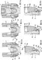
图11示出处于第一位置的第一实施例的骨锚固装置的垂直于杆的轴线截取的剖视图。Fig. 11 shows a cross-sectional view of the bone anchoring device of the first embodiment in a first position, taken perpendicular to the axis of the rod.
图12示出处于第二位置的图11的骨锚固装置的剖视图。Figure 12 shows a cross-sectional view of the bone anchoring device of Figure 11 in a second position.
图13示出处于第三位置的图11的骨锚固装置的剖视图。Figure 13 shows a cross-sectional view of the bone anchoring device of Figure 11 in a third position.
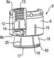
图14示出骨锚固装置的第二实施例的透视分解图。Figure 14 shows a perspective exploded view of a second embodiment of the bone anchoring device.
图15示出处于组装状态下的图14的骨锚固装置的透视图。Figure 15 shows a perspective view of the bone anchoring device of Figure 14 in an assembled state.
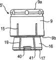
图16示出根据第二实施例的接收部主体的透视图。Fig. 16 shows a perspective view of a receiver body according to a second embodiment.
图17示出图16的接收部主体的侧视图。FIG. 17 shows a side view of the receiver body of FIG. 16 .
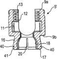
图18示出图16的接收部主体的垂直于杆的轴线截取的剖视图。FIG. 18 shows a cross-sectional view of the receiver body of FIG. 16 taken perpendicular to the axis of the rod.
图19示出图16的接收部主体的俯视图。FIG. 19 shows a top view of the receiver body of FIG. 16 .
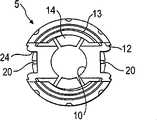
图20示出第二实施例的锁定环的透视图。Figure 20 shows a perspective view of the locking ring of the second embodiment.
图21示出图20的锁定环的沿图20中的线A-A截取的剖视图。FIG. 21 shows a cross-sectional view of the locking ring of FIG. 20 taken along line A-A in FIG. 20 .
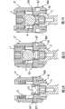
图22a示出处于第一位置的第二实施例的骨锚固装置的垂直于杆的轴线截取的剖视图。Figure 22a shows a cross-sectional view of the bone anchoring device of the second embodiment in a first position, taken perpendicular to the axis of the rod.
图22b示出图22a的细节放大图。Figure 22b shows an enlarged detail of Figure 22a.
图23a示出处于第二位置的图22a的骨锚固装置的剖视图。Figure 23a shows a cross-sectional view of the bone anchoring device of Figure 22a in a second position.
图23b示出图23a的细节放大图。Figure 23b shows an enlarged detail of Figure 23a.
图24a示出处于第三位置的图22a的骨锚固装置的剖视图。Figure 24a shows a cross-sectional view of the bone anchoring device of Figure 22a in a third position.
图24b示出图24a的细节放大图。Figure 24b shows an enlarged detail of Figure 24a.
图25示出骨锚固装置的第三实施例的透视分解图。Figure 25 shows a perspective exploded view of a third embodiment of the bone anchoring device.
图26示出处于组装状态下的图25的骨锚固装置的透视图。Figure 26 shows a perspective view of the bone anchoring device of Figure 25 in an assembled state.
图27示出第三实施例的接收部主体的俯视图。Fig. 27 shows a top view of the receiver body of the third embodiment.
图28示出处于第一位置的第三实施例的骨锚固装置的垂直于杆的轴线截取的剖视图。Figure 28 shows a cross-sectional view of the third embodiment bone anchoring device in a first position, taken perpendicular to the axis of the rod.
图29示出处于第二位置的图28的骨锚固装置的剖视图。Figure 29 shows a cross-sectional view of the bone anchoring device of Figure 28 in a second position.
图30示出处于第三位置的图28的骨锚固装置的剖视图。Figure 30 shows a cross-sectional view of the bone anchoring device of Figure 28 in a third position.
具体实施方式Detailed ways
如图1和2中所示,根据第一实施例的骨锚固装置包括骨螺钉形式的骨锚固元件1,所述骨锚固元件1具有螺纹锚杆2和具有弯曲表面部分的头部3,在该实施例中是截球形头部。头部3具有用于与拧入工具接合的凹槽4。所述骨锚固装置还包括接收部主体5,该接收部主体5用于接收杆6以便将杆6连接到骨锚固元件1。此外,内螺钉形式的封闭元件7设置用于将杆6固定在接收部主体5中。另外,所述骨锚固装置包括用于将头部锁定在接收部主体5中的锁定环8。As shown in FIGS. 1 and 2, a bone anchoring device according to a first embodiment comprises a
特别如图3-6中可以看到的,接收部主体5包括杆接收部分9,所述杆接收部分9基本为圆筒形并且具有第一端9a和相对的第二端9b。杆接收部分9具有设置在第二端9b处的同轴的第一孔10。第一孔10的直径小于骨锚固元件的头部3的直径。杆接收部分9还包括从第一端9a延伸到距离第二端9b一定距离处的同轴的第二孔11。第二孔11的直径大于第一孔10的直径,并且大于杆6的直径。基本为U形的凹槽12设置在杆接收部分9中,所述凹槽12从第一端9a延伸到第二端9b,凹槽12的直径略大于杆6的直径,这样杆6可以被放置在所述凹槽中并且可以在所述凹槽中被导引。借助于凹槽12形成两个自由支腿12a、12b,在所述两个自由支腿上设置有内螺纹13。所述内螺纹可以是公制螺纹、平螺纹、负角螺纹、锯齿螺纹或任意其它螺纹类型。优选地,采用诸如平螺纹或负角螺纹的螺纹形式,所述螺纹形式防止支腿12a、12b在拧入内螺钉7时张开。凹槽12的深度是使得杆6和内螺钉7可以插入支腿之间。在凹槽12的底部和支腿12a、12b之间设置有平坦段14,该平坦段14形成第二孔11的端部。As can be seen particularly in Figures 3-6, the
如图1、2、3和6中可以看到的,在杆接收部分中在凹槽12所形成的通道的每一端上设置有切口24。As can be seen in Figures 1, 2, 3 and 6, a
接收部主体5的杆接收部分9还包括多个同轴狭缝15,所述狭缝15从第二端9b延伸到距离第一端9a一定距离处,其中所述距离大致对应于内螺纹13的长度。狭缝15在第二端9b处开口并且特别如图1、3和6中可以看到的那样延伸穿过基本为U形的凹槽12中的平坦段14。在凹槽12的每一侧上设置有至少一个狭缝15,优选一个以上的狭缝。所述狭缝的数量根据应当由所述狭缝提供的挠曲度来提供。所述挠曲度可以取决于材料和壁厚和/或其它因素。The
杆接收部分在邻近第二端9b处具有环形凹槽30,通过该环形凹槽30在距离第二端一定距离处形成肩部31。凹槽30的深度是使得该凹槽可以与下面描述的锁定环8的一部分配合。Adjacent to the
接收部主体5在邻近第二端9b处包括头部接收部分16,所述头部接收部分16提供一个用于骨锚固元件1的头部3的容纳空间。头部接收部分16具有朝向第二端9b渐缩的外表面,并且头部接收部分16具有与第二端9b相对的开口端17。头部接收部分16的外表面可以部分地或全部地渐缩。所述头部接收部分16的外表面至少在头部3的最大直径的区域中渐缩。开口端17可以具有带圆角的边缘。The
特别如图3-5中可以看到的,杆接收部分9在第二端9b处的外径大于头部接收部分16在邻近第二端9b处的外径,并且还大于头部接收部分在开口端17处的外径。因此,头部接收部分16相对于杆接收部分9凹进。As can be seen particularly in FIGS. 3-5, the outer diameter of the
特别如图5中可以看到的,头部接收部分16具有内部中空段18,该内部中空段18形成用于骨锚固元件1的头部3的座。中空段18的形状与头部3的形状相适合,在所示实施例中,中空段18是用于容纳球形头部3的球形段。中空段18的尺寸制成为使得该中空段从侧面包围骨锚固元件的头部3并且遮盖包括头部3的最大直径的区域。As can be seen particularly in FIG. 5 , the
在头部接收部分16中设置有多个狭缝19,所述狭缝19通向开口端17并且从开口端17延伸到杆接收部分的第二端9b,并且所述狭缝19在杆接收部分9的狭缝15中连续,由此形成从头部接收部分的开口端17延伸到杆接收部分中的连续的狭缝。狭缝19的数量可以等于狭缝15的数量,然而根据头部接收部分16所需的挠性,狭缝19的数量可以更小或更大。另外,在头部接收部分16的侧面上还设置有狭缝20,如图6中所示,所述狭缝20与杆接收部分的基本为U形的凹槽12相邻。狭缝20终止于距离第二端9b一定距离处。头部接收部分16的挠性使得骨锚固元件的头部3可以通过使头部接收部分张开而插入并且可以通过压缩头部接收部分而被夹紧。杆接收部分中的狭缝15便于将接收部主体5用手安装在头部3上。A plurality of
下面将参考图1、2和7-13来描述锁定环8。锁定环8基本为圆柱形并且具有带渐缩内表面81a的第一部分81。所述第一部分的外表面也可以是渐缩的,以减小底部外径。第一部分81的尺寸是使得渐缩内表面81a能够接合头部接收部分16的外表面的渐缩部分,以在头部接收部分16上施加压缩力。第一部分的内表面81a也可以是弯曲的并且具有指向锁定环的中心的曲率(curvature)。The
此外,锁定环还具有圆柱形的第二部分82,该第二部分82的自由端形成能够抵靠杆接收部分的第二端9b的环形表面82a,如图11中所示。Furthermore, the locking ring also has a cylindrical
在直径上彼此相对地定位的两个突起21从环形表面82a朝着所述第二端的方向延伸。突起21所具有的高度使得当锁定环8处于头部3还没有被锁定的位置时,所述突起突出在基本为U形的凹槽12的底部的上方并且延伸进切口24中,如图11和12中所示。突起21的自由端22可以是弯曲的,特别是向内弯曲的,所具有的曲率对应于杆6的曲率。所述锁定环围绕接收部主体5的头部接收部分16布置成使得所述突起定位在凹槽12的合适位置处。借助于此,伸入凹槽12中的突起21防止锁定环在杆没有插入时发生转动。Two
锁定环的第三部分83由从环形表面82的外边缘突出的略微渐缩的环形凸缘形成。在所述凸缘中设置有多个同轴的狭缝84,所述狭缝84通向自由端并且使所述凸缘能够径向挠曲一定程度。如图11中所示,所述凸缘的高度大于头部接收部分16的凹槽30的高度。如图11中所示,所述凸缘的内径是使得所述锁定环能够夹紧杆接收部分9并由该挠性凸缘所产生的预应力保持。The
头部接收部分16的挠性以及头部接收部分在开口端17处的尺寸允许通过从自由端17将锁定环8组装在头部接收部分16上而安装锁定环8。因为头部接收部分16的外径小于杆接收部分9的外径,所以锁定环在径向方向上仅仅最小程度地突出超过杆接收部分。The flexibility of the
内螺钉7所具有的螺纹对应于设置在支腿上的内螺纹13。如果采用防止支腿张开的螺纹形式,那么诸如内螺钉7的单个封闭元件就足够了。这减小了骨锚固装置在径向方向上的尺寸。其它封闭元件,例如外螺母也是可以的。The
接收部主体5、锁定环8、内螺钉7以及骨锚固元件1均由具有足够强度的生物相容材料制成,例如由钛、不锈钢、生物相容合金或生物相容塑料材料制成。The receiving
可以通过将锁定环8安装在接收部主体5的头部接收部分16上并将螺钉头部3插入而预组装所述骨锚固装置。The bone anchoring device can be pre-assembled by mounting the
下面参考图11-13来解释锁定环的作用。如图11中所示,锁定环8的第一位置P1限定为使得锁定环处于该锁定环的最上面位置,其中环形表面82a抵靠杆接收部分9的第二端9b。在该位置,锁定环8通过挠性凸缘83施加的预应力被保持在杆接收部分上。头部接收部分16没有被压缩。在该位置,可以引入螺钉头部3。The function of the locking ring is explained below with reference to Figures 11-13. As shown in FIG. 11 , the first position P1 of the
第二位置P2是如图12中所示的预锁定位置。在该预锁定位置P2,锁定环已经向下位移,直到挠性凸缘83弹性地咬合在杆接收部分9处的凹槽30中并且挠性凸缘的上边缘抵靠凹槽的肩部31。因为凸缘83是略微渐缩的,所以锁定环由于挠性凸缘83施加的预应力被保持在该位置。锁定环的渐缩内表面81a在头部接收部分16上施加预应力,这样就预锁定了头部3。预锁定意味着在外科手术期间骨锚固元件1相对于接收部主体5的角位置被保持的状态形成时,只有通过在接收部主体或螺钉元件上施加一个附加力才能松开该角位置。因此,头部不可能无意中脱离。锁定环8的预锁定位置可以通过用手向下推动锁定环或者通过插入杆并拧入内螺钉以使杆压在突起21上来实现。The second positionP2 is the pre-lock position as shown in FIG. 12 . In this pre-locking positionP2 the locking ring has been displaced downwards until the
在图13中示出第三位置P3,该第三位置P3是锁定位置。该锁定位置限定为螺钉头部3最终被锁定在头部接收部分内的位置。在该锁定位置P3,渐缩内表面81a接合头部接收部分16的外表面,从而头部3由于头部接收部分的压缩而被锁定。所述锁定是通过最终拧紧内螺钉7由此向下压杆6来实现的。同时,防止了锁定环8进一步向下运动。A third position P3 is shown in FIG. 13 , which is the locked position. This locked position is defined as the position in which the
可以省略接收部主体中的凹槽30。还可以是凸缘83与接收部主体的第二端9b配合。The
使用中,将包括接收部主体、骨锚固元件和锁定环的预组装好的骨锚固装置拧入骨中。可以用拧入工具穿过第一孔10接近头部的凹槽4。锁定环8可能已经处于预锁定位置P2。为了将接收部相对于接收部将要连接到其上的杆对准,用手或者采用一个工具在接收部上施加一个附加力。一旦实现将杆相对于其它的骨锚固装置正确定位,就拧紧内螺钉7,由此使锁定环8向下位移到锁定位置P3。当锁定环8朝着头部接收部分的自由端17运动时,锁定环压缩它们的头部接收部分,由此锁定头部。内螺钉的最终拧紧同时将杆和头部锁定。In use, a pre-assembled bone anchoring device comprising a receiver body, a bone anchoring element and a locking ring is screwed into a bone. The groove 4 of the head can be accessed with a screw-in tool through the
可以由制造商或者在外科手术的准备过程中或者在任意时候预组装所述骨锚固装置。有利地,外科医生在外科手术前根据临床应用的特定需要来选择所需的接收部以及骨锚固元件。所述骨锚固装置的设计允许选择在锚固段的直径、长度和其它特征方面合适的骨锚固元件。因此,提供了包括接收部和几个骨锚固元件的模块化系统,然后可以独立地选择和适用所述模块化系统。The bone anchoring device may be preassembled by the manufacturer either during preparation for surgery or at any time. Advantageously, the surgeon selects the required receiving portion and the bone anchoring element according to the specific needs of the clinical application before the operation. The design of the bone anchoring device allows selection of a suitable bone anchoring element in terms of diameter, length and other characteristics of the anchoring segment. Thus, a modular system comprising a receiving portion and several bone anchoring elements is provided, which can then be selected and adapted independently.
在预锁定状态下,头部在内螺钉松开时保持被夹紧。这允许进一步调节杆。In the pre-locked state, the head remains clamped when the inner screw is loosened. This allows further adjustment of the rod.
下面参考图14-24来描述骨锚固装置的第二实施例。与第一实施例相同的部件具有相同的附图标记,并且对与第一实施例相同的部件将不再重复进行描述。骨锚固装置的第二实施例与第一实施例的区别在于接收部主体和锁定环的设计。接收部主体5′在第二端9b处不具有凹槽30。取而代之的是,接收部主体5′具有在头部接收部分16的开口端17附近的两个类似凹口的凹槽(notch-like recesses)40和邻近头部接收部分16的开口端17的环形凹槽41。类似凹口的凹槽40在直径上彼此相对地定位在杆接收部分9的U形凹槽12的两侧。所述类似凹口的凹槽距离开口端17一定距离。类似凹口的凹槽40的横截面可以是V形形状的,优选的是该类似凹口的凹槽的两个侧壁成45°角。借助于此,如图22b-图24b中可以最佳地看到的,形成了向下倾斜的表面40a。通过倾斜表面40a和凹槽41形成突起42,如下所述,突起42与锁定环的挠性部分配合。凹槽40的数量不限于两个。也可以提供较大数量的凹槽。这些凹槽优选地位于头部接收部分16的两个狭缝19之间的位置处。A second embodiment of the bone anchoring device is described below with reference to FIGS. 14-24. The same components as those of the first embodiment have the same reference numerals, and descriptions of the same components as those of the first embodiment will not be repeated. The second embodiment of the bone anchoring device differs from the first embodiment in the design of the receiver body and the locking ring. The receiver body 5' does not have a
锁定环80与锁定环8的区别在于:由环形凸缘形成的第三部分83′不具有狭缝,从而第三部分83′不是挠性的。此外,第一部分81的内表面部分81a′不是渐缩的,而是向内弯曲的,如图20-24中所示。然而,第一部分81的内表面部分81a′也可以是渐缩的。The locking
在锁定环80的第一部分81中形成有两个向内定向的弹性鼻部90,所述鼻部90在直径上彼此相对地定位在突起21的两侧、位于所述鼻部可以接合头部接收部分16的类似凹口的凹槽40的位置。在鼻部和外表面之间设置有允许弹性偏转鼻部90的中空部91。每个鼻部的尺寸是使得鼻部可以接合类似凹口的凹槽40。Formed in the
下面参考图22a-24b来描述根据第二实施例的骨锚固装置的作用。在第一位置P1(即插入位置),锁定环用它的环形表面82a抵靠杆接收部分9的第二端9b,如图22a和22b中所示。在该位置,鼻部90接合类似凹口的凹槽40。锁定环80通过弹性鼻部90施加的预应力被保持在该位置。在该位置,头部3可以从开口端17插入。The function of the bone anchoring device according to the second embodiment will be described below with reference to Figs. 22a-24b. In the first positionP1 , ie the inserted position, the locking ring abuts with its
如图23a和23b中所示,第二位置P2是预锁定位置,该预锁定位置限定为使得鼻部90接合邻近开口端17的环形凹槽41。该位置通过使锁定环80向下位移来实现。由此,鼻部90由倾斜表面40a导引直到鼻部咬合在突起42的下方。如果类似凹口的凹槽的侧壁的角度大约为45°,则容易实现预锁定位置P2。锁定环80只能通过应用工具或用手从预锁定位置释放,由此鼻部9必须从与环形凹槽41接合的状态释放。As shown in FIGS. 23 a and 23 b , the second position P2 is a pre-locked position defined such that the
如图24a和24b中所示,通过拧紧压在杆6上的内螺钉使锁定环80进一步向下运动,从而使锁定环80到达第三位置P3(即锁定位置)。在该锁定位置,鼻部位移离开凹槽41,从而所述鼻部位于开口端的下方。在该位置,锁定环80的内表面部分81a′压缩头部接收部分16,从而头部3被最终锁定。As shown in Figures 24a and 24b, the locking
应当注意的是,在该实施例中可以省略凸缘83′。It should be noted that
该骨锚固装置的临床使用与第一实施例的相似。The clinical use of the bone anchoring device is similar to that of the first embodiment.
下面参考图25-30来描述骨锚固装置的第三实施例。与第一实施例相同的部件具有相同的附图标记,并且对与第一实施例相同的部件将不再重复进行描述。骨锚固装置的第三实施例与第一实施例的区别在于接收部主体和锁定环的设计。接收部5″在其外壁中具有与锁定环800配合的弹簧部分。所述弹簧部分由在直径上相对地布置在杆接收部分的外壁(例如支腿12a、12b上)的同轴延伸的纵向元件100形成。元件100是类似片簧的部件,具有形成于杆接收部分的外壁中的向外弯折的部分(bent outward portion)101。A third embodiment of the bone anchoring device is described below with reference to FIGS. 25-30 . The same components as those of the first embodiment have the same reference numerals, and descriptions of the same components as those of the first embodiment will not be repeated. The third embodiment of the bone anchoring device differs from the first embodiment in the design of the receiver body and the locking ring. The receiving
向外弯折的部分101从所述壁伸出并且能够被弹性地压入壁中的相应空腔中。The outwardly
锁定环800与第一实施例的锁定环8的区别在于:凸缘83″不是挠性的。The
在第一位置,如图28中所示,锁定环800由弹簧部分100施加在凸缘83″上的预应力保持。头部接收部分没有被压缩,这就允许引入头部3。在图29中所示的第二预锁定位置中,锁定环从弹簧元件100释放并向下位移。所述弹簧元件可以作为限定所述预锁定位置的止挡。在图30中所示的第三位置,锁定环800进一步向下位移并且头部被锁定。In the first position, as shown in FIG. 28, the
其它形状和数量的弹簧部分也是可以的。Other shapes and numbers of spring portions are also possible.
可以有所示实施例的其它改进实施例。例如,骨锚固元件的头部可以具有任何其它形状,例如圆柱形状,由此提供允许螺钉元件相对于接收部绕单根轴线转动的单轴骨螺钉。头部3还可以是锥形形状的或者可以是其它形状的,并且头部接收部分的内部中空段18与该形状相适合。在另一改进实施例中,接收部主体5或至少头部接收部分16由提供一定程度弹性的生物相容塑料材料制成。在该情况下,可以省略所述狭缝。Other modified embodiments of the illustrated embodiment are possible. For example, the head of the bone anchoring element may have any other shape, such as a cylindrical shape, thereby providing a uniaxial bone screw allowing rotation of the screw element relative to the receiving portion about a single axis. The
与杆接合的锁定环的突起可以具有其它形状。例如,自由端的表面可以是平坦的或者可以是其它形状的。所述突起可以省略。The protrusion of the locking ring that engages the rod may have other shapes. For example, the surface of the free end may be flat or may be otherwise shaped. The protrusions may be omitted.
头部接收部分可以具有倾斜的开口端17,以允许头部在一个方向上的较大的角度。The head receiving portion may have an angled
头部接收部分的外表面可以是球面的,并且锁定环的内表面可以是渐缩的。The outer surface of the head receiving portion may be spherical and the inner surface of the locking ring may be tapered.
Claims (23)
Applications Claiming Priority (4)
| Application Number | Priority Date | Filing Date | Title |
|---|---|---|---|
| US14151208P | 2008-12-30 | 2008-12-30 | |
| EP08022553AEP2204129B1 (en) | 2008-12-30 | 2008-12-30 | Receiving part for receiving a rod for coupling the rod to a bone anchoring element and a bone anchoring device with such a receiving part |
| EP08022553.5 | 2008-12-30 | ||
| US61/141,512 | 2008-12-30 |
Publications (2)
| Publication Number | Publication Date |
|---|---|
| CN101766501A CN101766501A (en) | 2010-07-07 |
| CN101766501Btrue CN101766501B (en) | 2013-07-24 |
Family
ID=40587918
Family Applications (1)
| Application Number | Title | Priority Date | Filing Date |
|---|---|---|---|
| CN2009102663569AExpired - Fee RelatedCN101766501B (en) | 2008-12-30 | 2009-12-24 | Receiving part for receiving a rod for coupling the rod to a bone anchoring element and a bone anchoring device with such a receiving part |
Country Status (7)
| Country | Link |
|---|---|
| US (3) | US8506609B2 (en) |
| EP (1) | EP2204129B1 (en) |
| JP (1) | JP5610763B2 (en) |
| KR (1) | KR101512143B1 (en) |
| CN (1) | CN101766501B (en) |
| ES (1) | ES2378588T3 (en) |
| TW (1) | TWI463966B (en) |
Families Citing this family (102)
| Publication number | Priority date | Publication date | Assignee | Title |
|---|---|---|---|---|
| US7833250B2 (en) | 2004-11-10 | 2010-11-16 | Jackson Roger P | Polyaxial bone screw with helically wound capture connection |
| US7862587B2 (en) | 2004-02-27 | 2011-01-04 | Jackson Roger P | Dynamic stabilization assemblies, tool set and method |
| US8876868B2 (en) | 2002-09-06 | 2014-11-04 | Roger P. Jackson | Helical guide and advancement flange with radially loaded lip |
| US7621918B2 (en) | 2004-11-23 | 2009-11-24 | Jackson Roger P | Spinal fixation tool set and method |
| US7377923B2 (en) | 2003-05-22 | 2008-05-27 | Alphatec Spine, Inc. | Variable angle spinal screw assembly |
| US8926670B2 (en) | 2003-06-18 | 2015-01-06 | Roger P. Jackson | Polyaxial bone screw assembly |
| US7766915B2 (en) | 2004-02-27 | 2010-08-03 | Jackson Roger P | Dynamic fixation assemblies with inner core and outer coil-like member |
| US7776067B2 (en) | 2005-05-27 | 2010-08-17 | Jackson Roger P | Polyaxial bone screw with shank articulation pressure insert and method |
| US7527638B2 (en) | 2003-12-16 | 2009-05-05 | Depuy Spine, Inc. | Methods and devices for minimally invasive spinal fixation element placement |
| US7179261B2 (en) | 2003-12-16 | 2007-02-20 | Depuy Spine, Inc. | Percutaneous access devices and bone anchor assemblies |
| US11419642B2 (en) | 2003-12-16 | 2022-08-23 | Medos International Sarl | Percutaneous access devices and bone anchor assemblies |
| US11241261B2 (en) | 2005-09-30 | 2022-02-08 | Roger P Jackson | Apparatus and method for soft spinal stabilization using a tensionable cord and releasable end structure |
| US7160300B2 (en) | 2004-02-27 | 2007-01-09 | Jackson Roger P | Orthopedic implant rod reduction tool set and method |
| US8152810B2 (en) | 2004-11-23 | 2012-04-10 | Jackson Roger P | Spinal fixation tool set and method |
| JP2007525274A (en) | 2004-02-27 | 2007-09-06 | ロジャー・ピー・ジャクソン | Orthopedic implant rod reduction instrument set and method |
| US8475495B2 (en) | 2004-04-08 | 2013-07-02 | Globus Medical | Polyaxial screw |
| US7503924B2 (en) | 2004-04-08 | 2009-03-17 | Globus Medical, Inc. | Polyaxial screw |
| US8926672B2 (en) | 2004-11-10 | 2015-01-06 | Roger P. Jackson | Splay control closure for open bone anchor |
| WO2006057837A1 (en) | 2004-11-23 | 2006-06-01 | Jackson Roger P | Spinal fixation tool attachment structure |
| US9168069B2 (en) | 2009-06-15 | 2015-10-27 | Roger P. Jackson | Polyaxial bone anchor with pop-on shank and winged insert with lower skirt for engaging a friction fit retainer |
| US8444681B2 (en) | 2009-06-15 | 2013-05-21 | Roger P. Jackson | Polyaxial bone anchor with pop-on shank, friction fit retainer and winged insert |
| US9980753B2 (en) | 2009-06-15 | 2018-05-29 | Roger P Jackson | pivotal anchor with snap-in-place insert having rotation blocking extensions |
| US7901437B2 (en) | 2007-01-26 | 2011-03-08 | Jackson Roger P | Dynamic stabilization member with molded connection |
| CA2670988C (en) | 2006-12-08 | 2014-03-25 | Roger P. Jackson | Tool system for dynamic spinal implants |
| US10792074B2 (en) | 2007-01-22 | 2020-10-06 | Roger P. Jackson | Pivotal bone anchor assemly with twist-in-place friction fit insert |
| US8979904B2 (en) | 2007-05-01 | 2015-03-17 | Roger P Jackson | Connecting member with tensioned cord, low profile rigid sleeve and spacer with torsion control |
| ES2348814T3 (en) | 2007-07-31 | 2010-12-15 | Biedermann Motech Gmbh | ANCHORAGE DEVICE Ã “SEO. |
| AU2010260521C1 (en) | 2008-08-01 | 2013-08-01 | Roger P. Jackson | Longitudinal connecting member with sleeved tensioned cords |
| US11229457B2 (en) | 2009-06-15 | 2022-01-25 | Roger P. Jackson | Pivotal bone anchor assembly with insert tool deployment |
| CN103826560A (en) | 2009-06-15 | 2014-05-28 | 罗杰.P.杰克逊 | Polyaxial Bone Anchor with Socket Stem and Winged Inserts with Friction Fit Compression Collars |
| US8998959B2 (en) | 2009-06-15 | 2015-04-07 | Roger P Jackson | Polyaxial bone anchors with pop-on shank, fully constrained friction fit retainer and lock and release insert |
| US11464549B2 (en) | 2009-06-15 | 2022-10-11 | Roger P. Jackson | Pivotal bone anchor assembly with horizontal tool engagement grooves and insert with upright arms having flared outer portions |
| US9668771B2 (en) | 2009-06-15 | 2017-06-06 | Roger P Jackson | Soft stabilization assemblies with off-set connector |
| EP2485654B1 (en) | 2009-10-05 | 2021-05-05 | Jackson P. Roger | Polyaxial bone anchor with non-pivotable retainer and pop-on shank, some with friction fit |
| EP2384709B1 (en) | 2010-05-05 | 2012-09-05 | Biedermann Technologies GmbH & Co. KG | Receiving part for receiving a rod for coupling the rod to a bone anchoring element, bone anchoring device, method and tool for assembling the same |
| US12383311B2 (en) | 2010-05-14 | 2025-08-12 | Roger P. Jackson | Pivotal bone anchor assembly and method for use thereof |
| AU2011324058A1 (en) | 2010-11-02 | 2013-06-20 | Roger P. Jackson | Polyaxial bone anchor with pop-on shank and pivotable retainer |
| EP2737864B1 (en)* | 2010-12-10 | 2017-04-12 | Biedermann Technologies GmbH & Co. KG | Receiving part for receiving a rod for coupling the rod to a bone anchoring element and a bone anchoring device |
| EP2462888B1 (en)* | 2010-12-10 | 2015-02-18 | Biedermann Technologies GmbH & Co. KG | Receiving part for receiving a rod for coupling the rod to a bone anchoring element and bone anchoring device with such a receiving part |
| EP2659845A1 (en) | 2010-12-27 | 2013-11-06 | Biedermann Technologies GmbH & Co. KG | Polyaxial bone anchoring device |
| JP5865479B2 (en) | 2011-03-24 | 2016-02-17 | ロジャー・ピー・ジャクソン | Multiaxial bone anchor with compound joint and pop-mounted shank |
| US8888827B2 (en) | 2011-07-15 | 2014-11-18 | Globus Medical, Inc. | Orthopedic fixation devices and methods of installation thereof |
| US9198694B2 (en) | 2011-07-15 | 2015-12-01 | Globus Medical, Inc. | Orthopedic fixation devices and methods of installation thereof |
| US9993269B2 (en) | 2011-07-15 | 2018-06-12 | Globus Medical, Inc. | Orthopedic fixation devices and methods of installation thereof |
| US9186187B2 (en) | 2011-07-15 | 2015-11-17 | Globus Medical, Inc. | Orthopedic fixation devices and methods of installation thereof |
| US9358047B2 (en) | 2011-07-15 | 2016-06-07 | Globus Medical, Inc. | Orthopedic fixation devices and methods of installation thereof |
| EP2918237A1 (en)* | 2011-09-15 | 2015-09-16 | Biedermann Technologies GmbH & Co. KG | Polyaxial bone anchoring device with enlarged pivot angle |
| EP2574297B1 (en)* | 2011-09-30 | 2015-11-11 | Biedermann Technologies GmbH & Co. KG | Bone anchoring device and tool cooperating with such a bone anchoring device |
| US8911479B2 (en) | 2012-01-10 | 2014-12-16 | Roger P. Jackson | Multi-start closures for open implants |
| US20130211458A1 (en)* | 2012-02-13 | 2013-08-15 | Warsaw Orthopedic, Inc. | Bone fastener and methods of use |
| ES2552987T3 (en)* | 2012-07-03 | 2015-12-03 | Biedermann Technologies Gmbh & Co. Kg | Polyaxial bone anchoring device |
| EP2689734B1 (en)* | 2012-07-27 | 2016-09-14 | Biedermann Technologies GmbH & Co. KG | Polyaxial bone anchoring device with enlarged pivot angle |
| US9023087B2 (en)* | 2012-11-09 | 2015-05-05 | Blackstone Medical, Inc. | Percutaneous modular head-to-head cross connector |
| US8911478B2 (en) | 2012-11-21 | 2014-12-16 | Roger P. Jackson | Splay control closure for open bone anchor |
| US10058354B2 (en) | 2013-01-28 | 2018-08-28 | Roger P. Jackson | Pivotal bone anchor assembly with frictional shank head seating surfaces |
| US8852239B2 (en) | 2013-02-15 | 2014-10-07 | Roger P Jackson | Sagittal angle screw with integral shank and receiver |
| US9918746B2 (en) | 2013-09-01 | 2018-03-20 | Carbofix In Orthopedics Llc | Composite material spinal implant |
| US9566092B2 (en) | 2013-10-29 | 2017-02-14 | Roger P. Jackson | Cervical bone anchor with collet retainer and outer locking sleeve |
| US9717533B2 (en) | 2013-12-12 | 2017-08-01 | Roger P. Jackson | Bone anchor closure pivot-splay control flange form guide and advancement structure |
| US9451993B2 (en) | 2014-01-09 | 2016-09-27 | Roger P. Jackson | Bi-radial pop-on cervical bone anchor |
| US10064658B2 (en) | 2014-06-04 | 2018-09-04 | Roger P. Jackson | Polyaxial bone anchor with insert guides |
| US9597119B2 (en) | 2014-06-04 | 2017-03-21 | Roger P. Jackson | Polyaxial bone anchor with polymer sleeve |
| CN106796335B (en)* | 2014-07-25 | 2019-07-09 | 国家光学研究所 | Optical components mounted with tilt control of optics in the lens barrel |
| US10543021B2 (en) | 2014-10-21 | 2020-01-28 | Roger P. Jackson | Pivotal bone anchor assembly having an open ring positioner for a retainer |
| US9924975B2 (en) | 2014-10-21 | 2018-03-27 | Roger P. Jackson | Bone anchor having a snap-fit assembly |
| EP3023064B1 (en) | 2014-11-20 | 2019-01-09 | Biedermann Technologies GmbH & Co. KG | Receiving part for coupling a bone anchor to a rod and bone anchoring device with such a receiving part |
| FR3035318B1 (en)* | 2015-04-24 | 2017-05-19 | Medicrea Int | MATERIAL OF VERTEBRAL OSTEOSYNTHESIS |
| US9707013B2 (en)* | 2015-04-30 | 2017-07-18 | Warsaw Orthopedic, Inc. | Spinal implant system and methods of use |
| EP3092963B1 (en) | 2015-05-12 | 2017-07-12 | Biedermann Technologies GmbH & Co. KG | Coupling device for coupling a rod to a bone anchoring element and bone anchoring device with such a coupling device |
| EP3103406B1 (en) | 2015-06-10 | 2017-10-04 | Biedermann Technologies GmbH & Co. KG | Receiving part of a bone anchoring device and bone anchoring device with such a receiving part |
| EP3106110B1 (en) | 2015-06-16 | 2017-10-11 | Biedermann Technologies GmbH & Co. KG | Extension device for a bone anchor |
| EP3120791B1 (en) | 2015-07-24 | 2017-11-22 | Biedermann Technologies GmbH & Co. KG | Polyaxial bone anchoring device and instrument for use with the same |
| CN108697445B (en) | 2016-02-26 | 2022-04-19 | 美多斯国际有限公司 | Polyaxial bone fixation element |
| US10874438B2 (en) | 2016-07-13 | 2020-12-29 | Medos International Sarl | Bone anchor assemblies and related instrumentation |
| US10568667B2 (en) | 2016-07-13 | 2020-02-25 | Medos International Sàrl | Bone anchor assemblies and related instrumentation |
| US10463402B2 (en) | 2016-07-13 | 2019-11-05 | Medos International Sàrl | Bone anchor assemblies and related instrumentation |
| US10363073B2 (en) | 2016-07-13 | 2019-07-30 | Medos International Sàrl | Bone anchor assemblies and related instrumentation |
| EP4278998B1 (en)* | 2016-07-29 | 2025-05-21 | Zimmer Biomet Spine, Inc. | Bone anchor housing limiter |
| EP3278750B1 (en)* | 2016-08-04 | 2018-12-12 | Biedermann Technologies GmbH & Co. KG | Polyaxial bone anchoring device and system of an instrument and a polyaxial bone anchoring device |
| EP3287089B1 (en)* | 2016-08-24 | 2019-07-24 | Biedermann Technologies GmbH & Co. KG | Polyaxial bone anchoring device and system of an instrument and a polyaxial bone anchoring device |
| US20190262044A1 (en)* | 2016-09-16 | 2019-08-29 | Noah Roth | Bone anchor, instruments, and methods for use |
| WO2018183486A1 (en) | 2017-03-30 | 2018-10-04 | K2M, Inc. | Modular offset screw |
| US11298156B2 (en) | 2017-03-30 | 2022-04-12 | K2M, Inc. | Modular screw |
| AU2018243875B2 (en) | 2017-03-30 | 2022-05-26 | K2M, Inc. | Bone anchor apparatus and method of use thereof |
| US11026730B2 (en) | 2017-05-10 | 2021-06-08 | Medos International Sarl | Bone anchors with drag features and related methods |
| US10258386B2 (en)* | 2017-06-15 | 2019-04-16 | Warsaw Orthopedic, Inc. | Spinal construct and method |
| EP3476340B1 (en) | 2017-10-25 | 2021-06-02 | Biedermann Technologies GmbH & Co. KG | Polyaxial bone anchoring device |
| CN108542488A (en)* | 2018-02-10 | 2018-09-18 | 吉林百恩医疗器械科技有限公司 | A kind of push-in screw of arculae type |
| EP3536271B1 (en) | 2018-03-06 | 2022-05-04 | Biedermann Technologies GmbH & Co. KG | Polyaxial bone anchoring device and system of an instrument and a polyaxial bone anchoring device |
| US11571244B2 (en) | 2019-05-22 | 2023-02-07 | Nuvasive, Inc. | Posterior spinal fixation screws |
| EP3785649B1 (en) | 2019-08-30 | 2022-08-03 | Biedermann Technologies GmbH & Co. KG | Bone anchoring device |
| EP3821834B1 (en)* | 2019-11-14 | 2024-05-01 | Biedermann Technologies GmbH & Co. KG | Receiving part for coupling a rod to a bone anchor |
| EP3838196B1 (en)* | 2019-12-18 | 2024-01-31 | Biedermann Technologies GmbH & Co. KG | Coupling device and instrument for placing a coupling device to a head of a bone anchor |
| EP3878386B1 (en) | 2020-03-12 | 2023-08-30 | Biedermann Technologies GmbH & Co. KG | Coupling device for use with a bone anchoring element and bone anchoring device with such a coupling device |
| WO2021263088A1 (en) | 2020-06-26 | 2021-12-30 | K2M, Inc. | Modular head assembly |
| EP3988040B1 (en) | 2020-10-22 | 2025-09-03 | Biedermann Technologies GmbH & Co. KG | Coupling device for coupling a rod to a bone anchor |
| WO2022108875A1 (en) | 2020-11-19 | 2022-05-27 | K2M, Inc. | Modular head assembly for spinal fixation |
| US12364515B2 (en) | 2021-03-05 | 2025-07-22 | Medos International Sàrl | Multi-feature polyaxial screw |
| EP4074271B1 (en)* | 2021-04-15 | 2024-09-11 | Biedermann Technologies GmbH & Co. KG | Polyaxial bone anchoring device |
| EP4129220B1 (en)* | 2021-08-04 | 2024-07-03 | Biedermann Technologies GmbH & Co. KG | Coupling device for coupling a rod to a bone anchoring element and method of manufacturing the same |
| US20240398444A1 (en)* | 2021-09-14 | 2024-12-05 | Agmspine, Sia | A polyaxial spinal screw |
| CN114767247B (en)* | 2022-04-27 | 2025-08-12 | 航天中心医院 | Detachable screw and internal fixing device for pelvic anterior ring fixation |
Family Cites Families (39)
| Publication number | Priority date | Publication date | Assignee | Title |
|---|---|---|---|---|
| US578033A (en)* | 1897-03-02 | Wagon-jack | ||
| DE19509332C1 (en) | 1995-03-15 | 1996-08-14 | Harms Juergen | Anchoring element |
| US5578033A (en) | 1995-07-13 | 1996-11-26 | Fastenetix, L.L.C. | Advanced polyaxial locking hook and coupling element device for use with side loading rod fixation devices |
| US5609593A (en) | 1995-07-13 | 1997-03-11 | Fastenetix, Llc | Advanced polyaxial locking hook and coupling element device for use with top loading rod fixation devices |
| US5584834A (en) | 1995-07-13 | 1996-12-17 | Fastenetix, L.L.C. | Polyaxial locking screw and coupling element assembly for use with side loading rod fixation apparatus |
| US5586984A (en) | 1995-07-13 | 1996-12-24 | Fastenetix, L.L.C. | Polyaxial locking screw and coupling element assembly for use with rod fixation apparatus |
| US5964760A (en) | 1996-10-18 | 1999-10-12 | Spinal Innovations | Spinal implant fixation assembly |
| US5728098A (en)* | 1996-11-07 | 1998-03-17 | Sdgi Holdings, Inc. | Multi-angle bone screw assembly using shape-memory technology |
| US6010503A (en) | 1998-04-03 | 2000-01-04 | Spinal Innovations, Llc | Locking mechanism |
| PT1117336E (en)* | 1998-09-29 | 2004-10-29 | Synthes Ag | DEVICE FOR CONNECTING A LONGITUDINAL SUPPORT TO A BONUS FIXATION MEANS |
| US6254602B1 (en) | 1999-05-28 | 2001-07-03 | Sdgi Holdings, Inc. | Advanced coupling device using shape-memory technology |
| DE10157814B4 (en) | 2001-11-27 | 2004-12-02 | Biedermann Motech Gmbh | Closure device for securing a rod-shaped element in a holding element connected to a shaft |
| DE10157969C1 (en) | 2001-11-27 | 2003-02-06 | Biedermann Motech Gmbh | Element used in spinal and accident surgery comprises a shaft joined to a holding element having a U-shaped recess with two free arms having an internal thread with flanks lying at right angles to the central axis of the holding element |
| JP4130411B2 (en) | 2002-02-11 | 2008-08-06 | ジンテーズ ゲゼルシャフト ミト ベシュレンクテル ハフツング | Device for joining the vertical support and bone |
| DE10213855A1 (en) | 2002-03-27 | 2003-10-16 | Biedermann Motech Gmbh | Bone anchoring device for stabilizing bone segments and receiving part of a bone anchoring device |
| US20060200128A1 (en) | 2003-04-04 | 2006-09-07 | Richard Mueller | Bone anchor |
| US7087057B2 (en)* | 2003-06-27 | 2006-08-08 | Depuy Acromed, Inc. | Polyaxial bone screw |
| US20050080415A1 (en)* | 2003-10-14 | 2005-04-14 | Keyer Thomas R. | Polyaxial bone anchor and method of spinal fixation |
| US7090674B2 (en)* | 2003-11-03 | 2006-08-15 | Spinal, Llc | Bone fixation system with low profile fastener |
| US20060161153A1 (en) | 2004-10-25 | 2006-07-20 | Alphaspine, Inc. | Pedicle screw systems and methods of assembling/installing the same |
| US7901437B2 (en) | 2007-01-26 | 2011-03-08 | Jackson Roger P | Dynamic stabilization member with molded connection |
| WO2008137933A1 (en) | 2005-05-25 | 2008-11-13 | Alpinespine Llc | Low rider pedicle screw system |
| EP1769761B1 (en) | 2005-07-12 | 2008-09-10 | BIEDERMANN MOTECH GmbH | Bone anchoring device |
| EP1749489B1 (en) | 2005-08-03 | 2010-11-17 | BIEDERMANN MOTECH GmbH | Bone anchoring device |
| EP1926443B1 (en) | 2005-09-23 | 2013-04-03 | Synthes GmbH | Bone support apparatus |
| US7988694B2 (en) | 2005-09-29 | 2011-08-02 | K2M, Inc. | Spinal fixation system having locking and unlocking devices for use with a multi-planar, taper lock screw |
| WO2007075454A1 (en) | 2005-12-19 | 2007-07-05 | Synthes (U.S.A) | Polyaxial bone anchor with headless pedicle screw |
| US20080015576A1 (en)* | 2006-04-28 | 2008-01-17 | Whipple Dale E | Large diameter bone anchor assembly |
| US8162991B2 (en) | 2006-07-27 | 2012-04-24 | K2M, Inc. | Multi-planar, taper lock screw |
| US8167910B2 (en) | 2006-10-16 | 2012-05-01 | Innovative Delta Technology Llc | Bone screw and associated assembly and methods of use thereof |
| US7699876B2 (en)* | 2006-11-08 | 2010-04-20 | Ebi, Llc | Multi-axial bone fixation apparatus |
| US8162990B2 (en) | 2006-11-16 | 2012-04-24 | Spine Wave, Inc. | Multi-axial spinal fixation system |
| ES2348814T3 (en) | 2007-07-31 | 2010-12-15 | Biedermann Motech Gmbh | ANCHORAGE DEVICE Ã “SEO. |
| DE102007042958B4 (en) | 2007-08-30 | 2015-03-19 | Aesculap Ag | Surgical holding system |
| US8038701B2 (en) | 2007-10-22 | 2011-10-18 | K2M, Inc. | Uni-planar, taper lock bone screw |
| US8287576B2 (en) | 2007-10-23 | 2012-10-16 | K2M, Inc. | Mono-axial, taper lock bone screw |
| US20090105756A1 (en) | 2007-10-23 | 2009-04-23 | Marc Richelsoph | Spinal implant |
| US8398683B2 (en) | 2007-10-23 | 2013-03-19 | Pioneer Surgical Technology, Inc. | Rod coupling assembly and methods for bone fixation |
| US7789900B2 (en) | 2007-12-04 | 2010-09-07 | Expanding Orthopedics, Inc. | Double collet connector assembly for bone anchoring element |
- 2008
- 2008-12-30ESES08022553Tpatent/ES2378588T3/enactiveActive
- 2008-12-30EPEP08022553Apatent/EP2204129B1/enactiveActive
- 2009
- 2009-12-24KRKR1020090130950Apatent/KR101512143B1/ennot_activeExpired - Fee Related
- 2009-12-24TWTW098144636Apatent/TWI463966B/ennot_activeIP Right Cessation
- 2009-12-24JPJP2009291861Apatent/JP5610763B2/ennot_activeExpired - Fee Related
- 2009-12-24CNCN2009102663569Apatent/CN101766501B/ennot_activeExpired - Fee Related
- 2009-12-29USUS12/649,194patent/US8506609B2/enactiveActive
- 2013
- 2013-07-15USUS13/942,418patent/US9023086B2/enactiveActive
- 2015
- 2015-04-08USUS14/681,895patent/US9351766B2/enactiveActive
Also Published As
| Publication number | Publication date |
|---|---|
| US9351766B2 (en) | 2016-05-31 |
| US20140018859A1 (en) | 2014-01-16 |
| US20150272629A1 (en) | 2015-10-01 |
| ES2378588T3 (en) | 2012-04-16 |
| KR20100080397A (en) | 2010-07-08 |
| EP2204129A1 (en) | 2010-07-07 |
| US9023086B2 (en) | 2015-05-05 |
| JP5610763B2 (en) | 2014-10-22 |
| TWI463966B (en) | 2014-12-11 |
| US20100168800A1 (en) | 2010-07-01 |
| US8506609B2 (en) | 2013-08-13 |
| TW201023811A (en) | 2010-07-01 |
| CN101766501A (en) | 2010-07-07 |
| EP2204129B1 (en) | 2011-11-30 |
| KR101512143B1 (en) | 2015-04-22 |
| JP2010155077A (en) | 2010-07-15 |
Similar Documents
| Publication | Publication Date | Title |
|---|---|---|
| CN101766501B (en) | Receiving part for receiving a rod for coupling the rod to a bone anchoring element and a bone anchoring device with such a receiving part | |
| CN101828949B (en) | Receiving part for receiving a rod for coupling the rod to a bone anchoring element and a bone anchoring device with such a receiving part | |
| CN101791245B (en) | For receiving bar bar be connected to the acceptance division of bone anchoring element and there is the bone anchoring device of described acceptance division | |
| US11793552B2 (en) | Receiving part for receiving a rod for coupling the rod to a bone anchoring element and a bone anchoring device with such a receiving part | |
| US8998967B2 (en) | Receiving part for receiving a rod for coupling the rod to a bone anchoring element and a bone anchoring device with such a receiving part | |
| US9289246B2 (en) | Bone anchoring device | |
| CN102100577B (en) | Bone anchoring device | |
| WO2009124196A2 (en) | Top loading polyaxial spine screw assembly with one step lockup |
Legal Events
| Date | Code | Title | Description |
|---|---|---|---|
| C06 | Publication | ||
| PB01 | Publication | ||
| C10 | Entry into substantive examination | ||
| SE01 | Entry into force of request for substantive examination | ||
| ASS | Succession or assignment of patent right | Owner name:BIEDERMANN TECHNOLOGIES GMBH + AMP CO. KG Free format text:FORMER OWNER: BIEDERMANN MOTECH GMBH + CO. KG Effective date:20130407 | |
| C41 | Transfer of patent application or patent right or utility model | ||
| TA01 | Transfer of patent application right | Effective date of registration:20130407 Address after:German donaneschingen Applicant after:Biedermann Technologies GmbH & Co.KG Address before:German schwenningen Applicant before:Biedermann Technologies GmbH & Co.KG | |
| C14 | Grant of patent or utility model | ||
| GR01 | Patent grant | ||
| CF01 | Termination of patent right due to non-payment of annual fee | ||
| CF01 | Termination of patent right due to non-payment of annual fee | Granted publication date:20130724 |