CN101764420B - Quick-charging intelligent balanced managing device for electric field type secondary battery - Google Patents
Quick-charging intelligent balanced managing device for electric field type secondary batteryDownload PDFInfo
- Publication number
- CN101764420B CN101764420BCN2009102642276ACN200910264227ACN101764420BCN 101764420 BCN101764420 BCN 101764420BCN 2009102642276 ACN2009102642276 ACN 2009102642276ACN 200910264227 ACN200910264227 ACN 200910264227ACN 101764420 BCN101764420 BCN 101764420B
- Authority
- CN
- China
- Prior art keywords
- electric field
- power supply
- secondary battery
- type secondary
- field type
- Prior art date
- Legal status (The legal status is an assumption and is not a legal conclusion. Google has not performed a legal analysis and makes no representation as to the accuracy of the status listed.)
- Expired - Fee Related
Links
- 230000005684electric fieldEffects0.000titleclaimsabstractdescription423
- 238000004891communicationMethods0.000claimsabstractdescription28
- 239000003792electrolyteSubstances0.000claimsdescription11
- 238000006243chemical reactionMethods0.000claimsdescription10
- 239000000463materialSubstances0.000claimsdescription5
- 239000003014ion exchange membraneSubstances0.000claimsdescription3
- 238000009413insulationMethods0.000claims2
- 238000010586diagramMethods0.000description24
- 239000007773negative electrode materialSubstances0.000description21
- 230000003287optical effectEffects0.000description19
- 239000007774positive electrode materialSubstances0.000description19
- 230000005669field effectEffects0.000description18
- 239000003990capacitorSubstances0.000description15
- XEEYBQQBJWHFJM-UHFFFAOYSA-NIronChemical compound[Fe]XEEYBQQBJWHFJM-UHFFFAOYSA-N0.000description13
- WHXSMMKQMYFTQS-UHFFFAOYSA-NLithiumChemical compound[Li]WHXSMMKQMYFTQS-UHFFFAOYSA-N0.000description10
- 229910052744lithiumInorganic materials0.000description10
- 229910052742ironInorganic materials0.000description9
- 102100026110Protein THEMIS2Human genes0.000description8
- 101150104376Themis2 geneProteins0.000description8
- 238000002955isolationMethods0.000description6
- 230000008878couplingEffects0.000description5
- 238000010168coupling processMethods0.000description5
- 238000005859coupling reactionMethods0.000description5
- 238000007599dischargingMethods0.000description5
- BFDHFSHZJLFAMC-UHFFFAOYSA-Lnickel(ii) hydroxideChemical compound[OH-].[OH-].[Ni+2]BFDHFSHZJLFAMC-UHFFFAOYSA-L0.000description5
- 238000005342ion exchangeMethods0.000description4
- 239000011149active materialSubstances0.000description3
- OKTJSMMVPCPJKN-UHFFFAOYSA-NCarbonChemical compound[C]OKTJSMMVPCPJKN-UHFFFAOYSA-N0.000description2
- 101001081606Homo sapiens Islet cell autoantigen 1Proteins0.000description2
- UFHFLCQGNIYNRP-UHFFFAOYSA-NHydrogenChemical compound[H][H]UFHFLCQGNIYNRP-UHFFFAOYSA-N0.000description2
- 102100027640Islet cell autoantigen 1Human genes0.000description2
- 229910012851LiCoO 2Inorganic materials0.000description2
- 229910010707LiFePO 4Inorganic materials0.000description2
- 229910014778LiMn2O 4Inorganic materials0.000description2
- 229910013290LiNiO 2Inorganic materials0.000description2
- FYYHWMGAXLPEAU-UHFFFAOYSA-NMagnesiumChemical compound[Mg]FYYHWMGAXLPEAU-UHFFFAOYSA-N0.000description2
- RTAQQCXQSZGOHL-UHFFFAOYSA-NTitaniumChemical compound[Ti]RTAQQCXQSZGOHL-UHFFFAOYSA-N0.000description2
- HCHKCACWOHOZIP-UHFFFAOYSA-NZincChemical compound[Zn]HCHKCACWOHOZIP-UHFFFAOYSA-N0.000description2
- 229910052782aluminiumInorganic materials0.000description2
- XAGFODPZIPBFFR-UHFFFAOYSA-NaluminiumChemical compound[Al]XAGFODPZIPBFFR-UHFFFAOYSA-N0.000description2
- 229910052793cadmiumInorganic materials0.000description2
- BDOSMKKIYDKNTQ-UHFFFAOYSA-Ncadmium atomChemical compound[Cd]BDOSMKKIYDKNTQ-UHFFFAOYSA-N0.000description2
- 238000010292electrical insulationMethods0.000description2
- 238000004146energy storageMethods0.000description2
- 229910002804graphiteInorganic materials0.000description2
- 239000010439graphiteSubstances0.000description2
- 150000004678hydridesChemical class0.000description2
- 229910052739hydrogenInorganic materials0.000description2
- 239000001257hydrogenSubstances0.000description2
- 229910052749magnesiumInorganic materials0.000description2
- 239000011777magnesiumSubstances0.000description2
- 229910052987metal hydrideInorganic materials0.000description2
- 238000000034methodMethods0.000description2
- 238000012544monitoring processMethods0.000description2
- 239000011232storage materialSubstances0.000description2
- 229910052725zincInorganic materials0.000description2
- 239000011701zincSubstances0.000description2
- 101150075681SCL1 geneProteins0.000description1
- 230000002146bilateral effectEffects0.000description1
- 239000010406cathode materialSubstances0.000description1
- 239000013078crystalSubstances0.000description1
- 238000009792diffusion processMethods0.000description1
- 150000002500ionsChemical class0.000description1
- 230000014759maintenance of locationEffects0.000description1
- 229910052759nickelInorganic materials0.000description1
- PXHVJJICTQNCMI-UHFFFAOYSA-NnickelSubstances[Ni]PXHVJJICTQNCMI-UHFFFAOYSA-N0.000description1
- -1nickel metal hydrideChemical class0.000description1
- 230000002093peripheral effectEffects0.000description1
- 230000001105regulatory effectEffects0.000description1
- 101150111792sda1 geneProteins0.000description1
- 230000000087stabilizing effectEffects0.000description1
Images


Classifications
- Y—GENERAL TAGGING OF NEW TECHNOLOGICAL DEVELOPMENTS; GENERAL TAGGING OF CROSS-SECTIONAL TECHNOLOGIES SPANNING OVER SEVERAL SECTIONS OF THE IPC; TECHNICAL SUBJECTS COVERED BY FORMER USPC CROSS-REFERENCE ART COLLECTIONS [XRACs] AND DIGESTS
- Y02—TECHNOLOGIES OR APPLICATIONS FOR MITIGATION OR ADAPTATION AGAINST CLIMATE CHANGE
- Y02E—REDUCTION OF GREENHOUSE GAS [GHG] EMISSIONS, RELATED TO ENERGY GENERATION, TRANSMISSION OR DISTRIBUTION
- Y02E60/00—Enabling technologies; Technologies with a potential or indirect contribution to GHG emissions mitigation
- Y02E60/10—Energy storage using batteries
Landscapes
- Secondary Cells (AREA)
- Charge And Discharge Circuits For Batteries Or The Like (AREA)
Abstract
Translated fromChinese
Description
Translated fromChinese技术领域technical field
本发明涉及电动汽车的充电电池领域,具体涉及一种电场型二次电池与电场型二次电池组快速充电智能均衡管理装置。The invention relates to the field of rechargeable batteries for electric vehicles, in particular to an electric field type secondary battery and an electric field type secondary battery pack rapid charging intelligent equalization management device.
背景技术Background technique
目前电动汽车采用的动力二次电池主要有锂电池和高铁电池。而相对应的二次电池组智能管理系统是解决锂电池或高铁电池组均衡充电管理的装置。传统的锂电池和高铁电池存在缺点主要是:电池内部导电性差、离子扩散速度慢,高倍率充放电时,实际比容量低。而锂电池和高铁电池都存在低温性能差,一般情况下,对于单只电芯而言,其0℃时的容量保持率约60~70%,-10℃时为40~55%,-20℃时为20~40%,这样的低温性能显然不能满足动力电源的使用要求。所以传统的锂电池和高铁电池组智能管理系统是一种低速的二次电池组充电管理装置。由于传统的锂电池和高铁电池组无法实现有效的快速充电均衡管理的技术瓶颈,使得电动汽车动力电池组一次充电时间在8小时左右,影响了电动汽车市场推广与使用。At present, the power secondary batteries used in electric vehicles mainly include lithium batteries and high-speed iron batteries. The corresponding secondary battery pack intelligent management system is a device to solve the balanced charging management of lithium batteries or high-speed rail battery packs. The disadvantages of traditional lithium batteries and high-iron batteries are mainly: poor internal conductivity of batteries, slow ion diffusion speed, and low actual specific capacity when charging and discharging at high rates. Both lithium batteries and high-iron batteries have poor low-temperature performance. Generally, for a single battery cell, its capacity retention rate is about 60-70% at 0°C, 40-55% at -10°C, and 40-55% at -20°C. It is 20-40% at ℃, such low-temperature performance obviously cannot meet the requirements of power supply. Therefore, the traditional lithium battery and high-speed rail battery pack intelligent management system is a low-speed secondary battery pack charging management device. Due to the technical bottleneck that traditional lithium batteries and high-speed rail battery packs cannot achieve effective fast charging equalization management, the charging time of electric vehicle power battery packs is about 8 hours at a time, which affects the promotion and use of electric vehicle markets.
为了克服现有锂电池与高铁电池内部导电性差、低温性能差,并且无法提高快速充放电特性。专利号为200910032914.5的中国发明专利提出一种内置可控电场的二次电池及其快速充放电装置,该装置的技术方案是:电场型二次电池内,在离子交换隔膜的两侧分别设置有正极材料与负极材料,该正极材料与负极材料均设置在电解质中,所述正极材料与负极材料分别与电池的正极、负极连接,在该电场型二次电池中设置有一个内置电隔离的电场极板对,该电场极板对中的A极板设置在所述正极材料板的外侧,并与该正极材料板绝缘;该电场极板对中的B极板设置在所述负极材料板的外侧,并与该负极材料板绝缘;电场极板对中的A极板与电场极板对中的B极板分别与电场A极与电场B极端子相连。In order to overcome the poor internal conductivity and low-temperature performance of existing lithium batteries and high-iron batteries, and the inability to improve rapid charge and discharge characteristics. The Chinese invention patent with the patent number of 200910032914.5 proposes a secondary battery with a built-in controllable electric field and its fast charging and discharging device. The technical solution of the device is: in the electric field secondary battery, there are two The positive electrode material and the negative electrode material, the positive electrode material and the negative electrode material are both arranged in the electrolyte, the positive electrode material and the negative electrode material are connected to the positive electrode and the negative electrode of the battery respectively, and a built-in electrically isolated electric field is provided in the electric field type secondary battery A pole plate pair, the A pole plate in the electric field pole plate pair is arranged on the outside of the positive electrode material plate, and is insulated from the positive electrode material plate; the B pole plate in the electric field pole plate pair is arranged on the outside of the negative electrode material plate The outer side is insulated from the negative electrode material plate; the A pole plate in the electric field plate pair and the B pole plate in the electric field plate pair are respectively connected to the electric field A pole and the electric field B pole terminal.
电场型二次电池是指一种可控电场的二次电池,电场型二次电池与传统的二次电池最大不同在于,电场型二次电池本身有正、负输出电极端子外,还有一对输入电场电源电压的电场A极与电场B极端子,所以电场型二次电池本身有4个接线端子。电场型二次电池通过电场电源电压控制,能够有效提高电池内部导电性及低温特性,从而使电池的放电能较长时间地维持在较高电位水平,并在充电时明显缩短充电时间。电场型二次电池可以采用锂电池或高铁电池,也可以采用镍氢(Ni-HM)电池。二次电池是指在电池放电后可通过充电的方式使活性物质激活而继续使用的电池。二次电池系列中锂电池正极材料可以采用LiCoO2、LiMn2O4、LiNiO2、LiFePO4、LiFeMnPO4、LiFeYPO4等系列,而负极材料主要是石墨或钛酸盐。高铁电池正极采用高铁酸盐K2FeO4、BaFeO4等系列、负极材料可以是锌、铝、铁、镉或镁。镍氢(Ni-HM)电池正极采用氢氧化镍,负极采用由贮氢材料作为活性物质的氢化物电极。The electric field secondary battery refers to a secondary battery with a controllable electric field. The biggest difference between the electric field secondary battery and the traditional secondary battery is that the electric field secondary battery itself has positive and negative output electrode terminals, and a pair of The electric field A pole and the electric field B pole terminal of the electric field power supply voltage are input, so the electric field type secondary battery itself has four connection terminals. The electric field type secondary battery can effectively improve the internal conductivity and low temperature characteristics of the battery through the control of the electric field power supply voltage, so that the discharge of the battery can be maintained at a high potential level for a long time, and the charging time is significantly shortened during charging. The electric field type secondary battery can be a lithium battery or a high-iron battery, or a nickel metal hydride (Ni-HM) battery. A secondary battery refers to a battery that can be activated by charging the active material after the battery is discharged and continues to be used. Lithium battery cathode materials in the secondary battery series can be LiCoO2 , LiMn2O4 , LiNiO2 , LiFePO4 , LiFeMnPO4 , LiFeYPO4 and other series, while the negative electrode materials are mainly graphite or titanate. The positive electrode of the high-iron battery uses ferrate K2FeO4 , BaFeO4 and other series, and the negative electrode material can be zinc, aluminum, iron, cadmium or magnesium. The nickel hydroxide (Ni-HM) battery positive electrode uses nickel hydroxide, and the negative electrode uses a hydride electrode with hydrogen storage material as the active material.
发明内容Contents of the invention
本发明的目的是,针对电场型二次电池提供一种电动汽车电场型二次电池组快速充电智能均衡管理装置。The purpose of the present invention is to provide an electric vehicle electric vehicle electric field secondary battery rapid charging intelligent equalization management device for the electric field secondary battery.
实现本发明目的技术方案是:电场型二次电池组快速充电智能均衡管理装置,包括若干电场型二次电池,每个电场型二次电池中,在离子交换隔膜的两侧分别设置有正极材料与负极材料,该正极材料与负极材料均设置在电解质中,所述正极材料与负极材料分别与电池的正极、负极端子连接,在所述正极材料和负极材料的外侧分别设有电场极板对,正极材料与电场A极板之间电绝缘,负极材料与电场B极板之间电绝缘;其特征是,若干电场型二次电池组成电池组,电池组与微处理器电量采集与充放电电场控制单元连接,组成电场型二次电池控制单元BCU(Battery Control Unit),其中,所述微处理器电量采集与充放电电场控制电路,采用多路A/D转换及I2C通信接口的微处理器为核心电路,用于采集多个串连的电场型二次电池的电压、温度,并控制电场型二次电池快速充电时的电场电压;若干个电场型二次电池控制单元BCU通过I2C通讯总线相互连接,组成电场型二次电池组能源控制模块ECU(Energy Control Unit);所述电场型二次电池组能源控制模块ECU中,采用带I2C通信接口、CAN通信接口的微处理器管理控制多个电场型二次电池控制单元BCU;电场型二次电池组能源控制模块ECU中的微处理器通过CAN现场总线接口与中央电控系统连接。The technical solution for realizing the object of the present invention is: an electric field type secondary battery pack fast charging intelligent equalization management device, including a plurality of electric field type secondary batteries, in each electric field type secondary battery, positive electrode materials are respectively arranged on both sides of the ion exchange diaphragm and the negative electrode material, the positive electrode material and the negative electrode material are both arranged in the electrolyte, the positive electrode material and the negative electrode material are respectively connected to the positive electrode and the negative electrode terminal of the battery, and an electric field plate pair is respectively provided on the outside of the positive electrode material and the negative electrode material , electrical insulation between the positive electrode material and the electric field A plate, electrical insulation between the negative electrode material and the electric field B plate; it is characterized in that a number of electric field secondary batteries form a battery pack, and the battery pack and the microprocessor power collection and charging and discharging The electric field control unit is connected to form an electric field type secondary battery control unit BCU (Battery Control Unit), wherein the microprocessor power collection and charge and discharge electric field control circuit adopts multi-channel A/D conversion and I2 C communication interface The microprocessor is the core circuit, which is used to collect the voltage and temperature of multiple electric field secondary batteries connected in series, and to control the electric field voltage when the electric field secondary battery is quickly charged; several electric field secondary battery control units BCU pass The I2 C communication bus is connected to each other to form an ECU (Energy Control Unit) for the energy controlmodule of the electric field type secondary battery pack; The microprocessor manages and controls multiple electric field type secondary battery control units BCU; the microprocessor in the electric field type secondary battery pack energy control module ECU is connected to the central electronic control system through the CAN field bus interface.
本发明所述的电场型二次电池控制单元BCU(Battery Control Unit),是采用微处理器为核心的电路,采集多个串连的电场型二次电池的电压、温度,以及控制快速充电时,电场电压的控制。电场型二次电池控制单元BCU通过I2C(也可用I2C表示)通讯总线与电场型二次电池组能源控制模块ECU(Energy Control Unit)中微处理器I2C接口连接进行数据交换。The electric field type secondary battery control unit BCU (Battery Control Unit) of the present invention is a circuit using a microprocessor as the core to collect the voltage and temperature of a plurality of electric field type secondary batteries connected in series, and to control the time of fast charging. , control of electric field voltage. The electric field type secondary battery control unit BCU is connected to the microprocessor I2C interface in the electric field type secondary battery pack energy control module ECU (Energy Control Unit) through the I2 C (also can be represented by I2C) communication bus for data exchange.
具体地说:本发明所述的电场型二次电池装置,其结构主要由:电场极板A、正极材料、离子交换隔膜、电解质、负极材料、电场极板B所组成,其中电场极板A、电场极板B在电气连接有电场A极与电场B极端子,组成电场A极与电场B极双端子的电场型二次电池装置。所述的电场型二次电池装置,也可形成单电场A极的电场型二次电池装置与单电场B极的电场型二次电池装置,称之为:电场A极二次电池与电场B极二次电池。Specifically: the electric field type secondary battery device of the present invention, its structure mainly is made up of: electric field plate A, positive electrode material, ion exchange membrane, electrolyte, negative electrode material, electric field plate B, wherein electric field plate A , The electric field plate B is electrically connected with the electric field A pole and the electric field B pole terminal, forming an electric field type secondary battery device with two terminals of the electric field A pole and the electric field B pole. The electric field type secondary battery device can also form the electric field type secondary battery device of the single electric field A pole and the electric field type secondary battery device of the single electric field B pole, which is called: the electric field A pole secondary battery and the electric field B pole Extremely secondary battery.
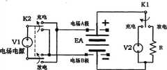
本发明所述的电场型二次电池快速充放电原理,在电路原理有三种形式,电场型二次电池充放电方式;电场A极二次电池充放电方式;电场B极二次电池充放电方式;其充放电电路原理图中K2为双联开关,K1为单联开关,并且K1、K2开关同步切换;V1为电场电源,V2为充电电源,V1与V2电源相互隔离;电路中R为负载。当K1、K2开关同步切换到充电状态,此时电场电源的正极连接电场极板A,电场电源的负极连接电场极板B,此时电场型二次电池内部电场电源的电场方向与充电电源的电场方向相同;当K1、K2开关同步切换到放电状态,此时电场电源的正极连接电场极板B,电场电源的负极连接电场极板A,此时电场型二次电池内部电场电源的电场方向与电池自身放电的内电场方向相同;电场型二次电池快速充放电电路原理,参看附图2中图2A。由于电场极板A、电场极板B与二次电池内部是电隔离,同理可知,电场A极二次电池与电场B极二次电池快速充放电方式。The electric field type secondary battery rapid charge and discharge principle described in the present invention has three forms in the circuit principle, the electric field type secondary battery charge and discharge mode; the electric field A pole secondary battery charge and discharge mode; the electric field B pole secondary battery charge and discharge mode In the schematic diagram of its charging and discharging circuit, K2 is a double switch, K1 is a single switch, and K1 and K2 switches are switched synchronously; V1 is the electric field power supply, V2 is the charging power supply, and V1 and V2 power supplies are isolated from each other; R in the circuit is the load . When the K1 and K2 switches are switched to the charging state synchronously, the positive pole of the electric field power supply is connected to the electric field plate A, and the negative pole of the electric field power supply is connected to the electric field plate B. At this time, the electric field direction of the electric field power supply inside the electric field secondary battery is the same as that of the charging power supply. The direction of the electric field is the same; when the K1 and K2 switches are switched to the discharge state synchronously, the positive pole of the electric field power supply is connected to the electric field plate B, and the negative pole of the electric field power supply is connected to the electric field plate A. At this time, the electric field direction of the electric field power supply inside the electric field secondary battery The direction of the internal electric field is the same as that of the self-discharge of the battery; for the principle of the electric field type secondary battery rapid charge and discharge circuit, refer to Figure 2A in Figure 2. Since the electric field plate A and the electric field plate B are electrically isolated from the inside of the secondary battery, it can be known that the electric field A pole secondary battery and the electric field B pole secondary battery are quickly charged and discharged.
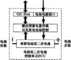
本发明所述的电场型二次电池控制单元BCU结构内部,是由多个串联电场型二次电池、微处理器电量采集与电池充电电场控制电路组成。电场型二次电池控制单元BCU的外部有电池正、负极输出端;外电场电源正、负端子接口;I2C通讯总线接口。本实施例的电场型二次电池控制单元BCU结构内部由4个电场型二次电池串联;输出端正、负极电压为4倍电场型二次电池电压;外电场电源正、负端子接口,是充电时电场电源的接口;I2C通讯总线接口是多个电场型二次电池控制单元BCU相互连接的的通信接口。The electric field type secondary battery control unit BCU of the present invention is composed of a plurality of electric field type secondary batteries connected in series, a microprocessor power collection and a battery charging electric field control circuit. The external electric field type secondary battery control unit BCU has battery positive and negative output terminals; external electric field power supply positive and negative terminal interfaces; I2C communication bus interface. The electric field type secondary battery control unit BCU of this embodiment is internally composed of 4 electric field type secondary batteries in series; the positive and negative pole voltages of the output terminals are 4 times the electric field type secondary battery voltage; The interface of the electric field power supply; the I2C communication bus interface is a communication interface for connecting multiple electric field type secondary battery control units BCU to each other.
本发明所述的电场型二次电池组能源控制模块ECU结构,是多个电场型二次电池控制单元BCU通过串并联的形式组成(能源控制模块ECU结构中最多不超过125个控制单元BCU,可以管理电场型二次电池数为125×4);电场型二次电池组能源控制模块ECU中微处理器I2C通讯总线接口与多个电场型二次电池控制单元BCU的I2C通讯总线接口连接,进行集中管理与控制多个电场型二次电池控制单元BCU;电场型二次电池组能源控制模块ECU中有快速充电电场电源,电场电源的正、负极,相对应连接到多个电场型二次电池控制单元BCU的电场电源接口;电场型二次电池组能源控制模块ECU中微处理器的CAN现场总线接口与中央电控系统连接,形成电场型二次电池组快速充电智能均衡管理装置,也就是说,电场型二次电池组能源控制模块ECU通过CAN Bus与汽车中央电控系统连接称之为:电动汽车电场型二次电池组快速充电智能均衡管理装置。The electric field type secondary battery pack energy control module ECU structure of the present invention is composed of a plurality of electric field type secondary battery control units BCU in the form of series and parallel connection (the energy control module ECU structure does not exceed 125 control units BCU at most, The number of electric field type secondary batteries that can be managed is 125×4); the microprocessor I2C communication bus interface in the energy control module ECU of the electric field type secondary battery pack is connected to the I2C communication bus interface of multiple electric field type secondary battery control units BCU, Centralized management and control of multiple electric field type secondary battery control units BCU; electric field type secondary battery pack energy control module ECU has a fast charging electric field power supply, and the positive and negative poles of the electric field power supply are correspondingly connected to multiple electric field type secondary battery packs. The electric field power interface of the battery control unit BCU; the CAN field bus interface of the microprocessor in the electric field type secondary battery pack energy control module ECU is connected with the central electronic control system to form an electric field type secondary battery pack fast charging intelligent equalization management device. That is to say, the electric field type secondary battery pack energy control module ECU is connected with the automobile central electronic control system through CAN Bus, which is called: electric vehicle electric field type secondary battery pack fast charging intelligent equalization management device.
本发明所述的电场型二次电池组快速充电智能均衡管理装置结构,也可以由多个电场型二次电池组能源控制模块ECU串联或并联,并通过CAN现场总线接口与其它领域应用的中央电控系统连接,形成其它领域使用的超大型储能电堆电场型二次电池组快速充电智能均衡管理装置;中央电控系统可以管理控制大于127个电场型二次电池组能源控制模块ECU,总体可管理电场型二次电池数大于127×(125×4)=63500个。The structure of the electric field type secondary battery pack fast charging intelligent equalization management device described in the present invention can also be connected in series or in parallel by a plurality of electric field type secondary battery pack energy control module ECUs, and communicate with the center of other field applications through the CAN field bus interface The electronic control system is connected to form a super-large energy storage stack electric field type secondary battery pack fast charging intelligent equalization management device used in other fields; the central electronic control system can manage and control more than 127 electric field type secondary battery pack energy control modules ECU, The total number of manageable electric field secondary batteries is greater than 127×(125×4)=63500.
附图说明Description of drawings
图1A本发明电场型二次电池结构图;Fig. 1A is a structural diagram of an electric field type secondary battery of the present invention;
图1B本发明电场A极二次电池结构图;Fig. 1B is a structural diagram of the electric field A pole secondary battery of the present invention;
图1C本发明电场B极二次电池结构图;Fig. 1C is a structural diagram of the electric field B pole secondary battery of the present invention;
图2A本发明电场型二次电池充放电电路原理图Fig. 2A schematic diagram of electric field type secondary battery charging and discharging circuit of the present invention
图2B本发明电场A极二次电池充放电电路原理图Fig. 2B The schematic diagram of the charge and discharge circuit of the electric field A pole secondary battery of the present invention
图2C本发明电场B极二次电池充放电电路原理图Fig. 2C schematic diagram of charge and discharge circuit of electric field B pole secondary battery of the present invention
图3本发明电场型二次电池控制单元BCU结构图;Fig. 3 structure diagram of electric field type secondary battery control unit BCU of the present invention;
图4本发明电动汽车电场型二次电池组能源控制模块ECU系统框图;Fig. 4 electric vehicle electric field type secondary battery pack energy control module ECU system block diagram of the present invention;
图5本发明多电场型二次电池组能源控制模块ECU组成电堆系统框图;Fig. 5 is a block diagram of the electric stack system composed of the multi-electric field type secondary battery pack energy control module ECU of the present invention;
图6本发明电场型二次电池控制单元BCU电路原理图;Fig. 6 is the electric field type secondary battery control unit BCU circuit principle diagram of the present invention;
图7本发明电场型二次电池组能源控制模块ECU电路原理图;Fig. 7 is the electric field type secondary battery pack energy control module ECU circuit schematic diagram of the present invention;
图8本发明电场A极二次电池控制单元BCU电路原理图;Fig. 8 is the electric field A pole secondary battery control unit BCU circuit principle diagram of the present invention;
图9本发明电场B极二次电池控制单元BCU电路原理图。Fig. 9 is a schematic circuit diagram of the electric field B pole secondary battery control unit BCU of the present invention.
具体实施方式Detailed ways
下面结合附图和实施例作进一步说明。Further description will be made below in conjunction with drawings and embodiments.
实施例1Example 1
电场型二次电池装置,其结构主要由:电场极板A、正极材料、离子交换隔膜、电解质、负极材料、电场极板B所组成,其中电场极板A、电场极板B在电气连接有电场A极与电场B极端子,参看附图1中图1A所示。所述的电场型二次电池装置,也可形成电场A极二次电池装置与电场B极二次电池装置,参看附图1中图1B、1C所示。Electric field type secondary battery device, its structure is mainly composed of: electric field plate A, positive electrode material, ion exchange diaphragm, electrolyte, negative electrode material, electric field plate B, wherein electric field plate A, electric field plate B are electrically connected The terminals of the electric field A pole and the electric field B pole are shown in Fig. 1A in the accompanying
参照图1中图1A所示,一种电场型二次电池结构是由:电场电极板A 1.1、绝缘层A 1.2、正极材料板1.3、负极材料板1.4、电场电极板B 1.5、绝缘层B1.6、离子交换隔膜1.7、电解质1.8所组成的结构。其中绝缘层A 1.2、绝缘层B 1.6材料中间包袱有电场电极板A 1.1、电场电极板B 1.5,而电场电极板A1.1、电场电极板B 1.5与电池的正极材料板与负极材料板,以及电解质1.8形成电隔离。Referring to Figure 1A in Figure 1, an electric field secondary battery structure is composed of: electric field electrode plate A 1.1, insulating layer A 1.2, positive electrode material plate 1.3, negative electrode material plate 1.4, electric field electrode plate B 1.5, insulating layer B1 .6. A structure composed of an ion exchange membrane 1.7 and an electrolyte 1.8. Among them, the insulating layer A 1.2 and the insulating layer B 1.6 are packed with the electric field electrode plate A 1.1 and the electric field electrode plate B 1.5, and the electric field electrode plate A1.1, the electric field electrode plate B 1.5 and the positive electrode material plate and the negative electrode material plate of the battery, And the electrolyte 1.8 forms the electrical isolation.
参照图1中图1B所示,一种电场A极二次电池结构是由:电场电极板A1.1、绝缘层A 1.2、正极材料板1.3、负极材料板1.4、离子交换隔膜1.7、电解质1.8所组成的结构。其中绝缘层A 1.2材料中间包袱有电场电极板A 1.1,而电场电极板A 1.1与电池的正极材料板与电解质1.8形成电隔离。Referring to Figure 1B in Figure 1, an electric field A pole secondary battery structure is composed of: electric field electrode plate A1.1, insulating layer A1.2, positive electrode material plate 1.3, negative electrode material plate 1.4, ion exchange diaphragm 1.7, electrolyte 1.8 composed structure. Among them, the insulating layer A 1.2 is covered with an electric field electrode plate A 1.1, and the electric field electrode plate A 1.1 is electrically isolated from the positive electrode material plate of the battery and the electrolyte 1.8.
参照图1中图1C所示,一种电场B极二次电池结构是由:正极材料板1.3、负极材料板1.4、电场电极板B 1.5、绝缘层B 1.6、离子交换隔膜1.7、电解质1.8所组成的结构。其中绝缘层B 1.6材料中间包袱有电场电极板B1.5,而电场电极板B 1.5与电池的负极材料板与电解质1.8形成电隔离。电场型二次电池结构中,选择锂电池,其正极材料可以采用LiCoO2、LiMn2O4、LiNiO2、LiFePO4、LiFeMnPO4、LiFeYPO4等系列,而负极材料主要是石墨或钛酸盐。选择高铁电池,其正极可以采用高铁酸盐K2FeO4、BaFeO4等系列、负极材料可以是锌、铝、铁、镉或镁。选择镍氢(Ni-HM)电池,其正极材料可以采用氢氧化镍,负极采用贮氢材料作为活性物质的氢化物电极。Referring to Fig. 1C in Fig. 1, an electric field B pole secondary battery structure is composed of: positive electrode material plate 1.3, negative electrode material plate 1.4, electric field electrode plate B 1.5, insulating layer B 1.6, ion exchange diaphragm 1.7, electrolyte 1.8 composed structure. The electric field electrode plate B1.5 is carried in the middle of the material of the insulating layer B1.6, and the electric field electrode plate B1.5 is electrically isolated from the negative electrode material plate of the battery and the electrolyte 1.8. In the structure of the electric field secondary battery, lithium batteries are selected. The positive electrode materials can be LiCoO2 , LiMn2O4 , LiNiO2 , LiFePO4 , LiFeMnPO4 , LiFeYPO4 and other series, while the negative electrode materials are mainly graphite or titanate. If you choose a high-speed iron battery, the positive electrode can use ferrate K2FeO4 , BaFeO4 and other series, and the negative electrode material can be zinc, aluminum, iron, cadmium or magnesium. Select nickel-metal hydride (Ni-HM) batteries, the positive electrode material can be nickel hydroxide, and the negative electrode can use hydrogen storage material as the hydride electrode of the active material.
电场型二次电池快速充放电原理,在电路原理有三种形式,电场型二次电池充放电方式;电场A极二次电池充放电方式;电场B极二次电池充放电方式;其充放电电路原理图中K2为双联开关,K1为单联开关,并且K1、K2开关同步切换;V1为电场电源,V2为充电电源,V1与V2电源相互隔离;电路中R为负载。当K1、K2开关同步切换到充电状态,此时电场电源的正极连接电场极板A,电场电源的负极连接电场极板B,此时电场型二次电池内部电场电源的电场方向与充电电源的电场方向相同;当K1、K2开关同步切换到放电状态,此时电场电源的正极连接电场极板B,电场电源的负极连接电场极板A,此时电场型二次电池内部电场电源的电场方向与电池自身放电的内电场方向相同;电场型二次电池快速充放电电路原理,参看附图2中图2A。由于电场极板A、电场极板B与二次电池内部是电隔离,同理,电场A极二次电池与电场B极二次电池快速充放电方式,参看附图2中图2B、2C所示。The principle of rapid charge and discharge of electric field secondary batteries has three forms in the circuit principle, electric field secondary battery charge and discharge mode; electric field A pole secondary battery charge and discharge mode; electric field B pole secondary battery charge and discharge mode; its charge and discharge circuit In the schematic diagram, K2 is a double switch, K1 is a single switch, and the K1 and K2 switches are switched synchronously; V1 is the electric field power supply, V2 is the charging power supply, and the V1 and V2 power supplies are isolated from each other; R in the circuit is the load. When the K1 and K2 switches are switched to the charging state synchronously, the positive pole of the electric field power supply is connected to the electric field plate A, and the negative pole of the electric field power supply is connected to the electric field plate B. At this time, the electric field direction of the electric field power supply inside the electric field secondary battery is the same as that of the charging power supply. The direction of the electric field is the same; when the K1 and K2 switches are switched to the discharge state synchronously, the positive pole of the electric field power supply is connected to the electric field plate B, and the negative pole of the electric field power supply is connected to the electric field plate A. At this time, the electric field direction of the electric field power supply inside the electric field secondary battery The direction of the internal electric field is the same as that of the self-discharge of the battery; for the principle of the electric field type secondary battery rapid charge and discharge circuit, refer to Figure 2A in Figure 2. Since the electric field plate A, the electric field plate B are electrically isolated from the inside of the secondary battery, similarly, the rapid charge and discharge mode of the secondary battery at the electric field A pole and the electric field B pole secondary battery can be seen in Figure 2B and 2C in Figure 2 Show.
电场型二次电池控制单元BCU结构,是由多个单体电场型二次电池、微处理器电量采集与电池充电电场控制电路组成。本实施例电场型二次电池控制单元BCU内部共有4个电场型二次电池串联,控制单元BCU的外部有电池正、负极输出端;外电场电源接口、I2C通讯总线接口,其结构框图,参看附图3所示。The BCU structure of the electric field type secondary battery control unit is composed of a plurality of single electric field type secondary batteries, a microprocessor power collection and a battery charging electric field control circuit. In this embodiment, there are 4 electric field secondary batteries connected in series inside the electric field secondary battery control unit BCU, and there are battery positive and negative output terminals outside the control unit BCU; external electric field power supply interface, I2C communication bus interface, and its structural block diagram, see Shown in accompanying
电动汽车电场型二次电池组能源控制模块ECU系统框图,参看附图4所示。电场型二次电池组能源控制模块ECU结构,是多个电场型二次电池控制单元BCU通过串并联的形式组成(能源控制模块ECU结构中最多不超过125个控制单元BCU,可以管理电场型二次电池数为125×4);电场型二次电池组能源控制模块ECU中微处理器I2C通讯总线接口与多个电场型二次电池控制单元BCU的I2C通讯总线接口连接,进行集中管理与控制多个电场型二次电池控制单元BCU;电场型二次电池组能源控制模块ECU中有快速充电电场电源,电场电源的正、负极,相对应连接到多个电场型二次电池控制单元BCU的电场电源接口;电场型二次电池组能源控制模块ECU中微处理器的CAN现场总线接口与中央电控系统连接,形成电场型二次电池组快速充电智能均衡管理装置;电场型二次电池组能源控制模块ECU通过CAN Bus与汽车中央电控系统连接称之为:电动汽车电场型二次电池组快速充电智能均衡管理装置。The ECU system block diagram of the electric field type secondary battery pack energy control module for electric vehicles is shown in Figure 4. The ECU structure of the energy control module of the electric field type secondary battery pack is composed of multiple electric field type secondary battery control units BCU connected in series and parallel (the maximum number of control units BCU in the energy control module ECU structure is no more than 125 control units BCU, which can manage the electric field type secondary battery The number of secondary batteries is 125×4); the I2C communication bus interface of the microprocessor in the ECU of the electric field secondary battery pack energy control module is connected with the I2C communication bus interfaces of multiple electric field secondary battery control units BCU for centralized management and control Multiple electric field type secondary battery control units BCU; the electric field type secondary battery pack energy control module ECU has a fast charging electric field power supply, and the positive and negative poles of the electric field power supply are correspondingly connected to multiple electric field type secondary battery control unit BCUs Electric field power supply interface; the CAN field bus interface of the microprocessor in the energy control module ECU of the electric field type secondary battery pack is connected with the central electronic control system to form an electric field type secondary battery pack fast charging intelligent equalization management device; the electric field type secondary battery pack The energy control module ECU is connected with the central electronic control system of the car through the CAN Bus, which is called: electric vehicle electric field type secondary battery pack fast charging intelligent equalization management device.
电场型二次电池组快速充电智能均衡管理装置结构,也可以由多个电场型二次电池组能源控制模块ECU串联或并联,并通过CAN现场总线接口与其它领域应用的中央电控系统连接,形成其它领域使用的超大型储能电堆电场型二次电池组快速充电智能均衡管理装置;中央电控系统可以管理控制大于127个电场型二次电池组能源控制模块ECU,总体可管理电场型二次电池数大于127×(125×4)=63500个。,其多电场型二次电池组能源控制模块ECU组成电堆系统框图,参看附图5所示。The structure of the electric field type secondary battery pack fast charging intelligent equalization management device can also be connected in series or in parallel by multiple electric field type secondary battery pack energy control module ECUs, and connected with the central electronic control system applied in other fields through the CAN field bus interface. Form a super-large energy storage stack electric field type secondary battery pack fast charging intelligent equalization management device used in other fields; the central electronic control system can manage and control more than 127 electric field type secondary battery pack energy control module ECUs, and can manage electric field type secondary battery packs in general The number of secondary batteries is more than 127×(125×4)=63500. , the multi-electric field type secondary battery pack energy control module ECU constitutes the block diagram of the stack system, as shown in Figure 5.
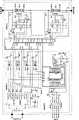
参照图6所示,本实施例一种电场型二次电池控制单元BCU电路原理图:是由3大电路部份组成。电路部分1主要由:稳压电路U1;隔离式DC/DC转换器U2;光藕合器T1、T3、T5、T7;场效应开关管T2、T4、T6、T8;电阻R1-R8;电容C1-C7;电容CA4所组成。其中稳压电路U1是提供5V的稳压工作电压的三端稳压器。隔离式DC/DC转换器U2是将外电场电压转换成相互隔离的5组直流输出电源,并且该5组输出电源也相互隔离,每组输出电压≥2EA,EA为电场型二次电池的标称电压,其中有4组电场电源与1组电路工作电源。光藕合器T1、T3、T5、T7;场效应开关管T2、T4、T6、T8;电阻R1-R8;组成4组光隔离电场电源开关电路,每组电场电源对应连接4个电场型二次电池的电场A极与电场B极,4组电场电源分别标示为:V1B、V1A;V2B、V2A;V3B、V3A;V4B、V4A,对应接入电场型二次电池EA1的电场B极、电场A极;EA2的电场B极、电场A极;EA3的电场B极、电场A极;EA4的电场B极、电场A极。在微处理器控制端PC0、PC1、PD0、PA4为低电平时,4组光隔离电场电源开关电路中场效应电场电源开关导通,电场电压加到二次电池EA1、EA2、EA3、EA4的电场极A、B端,此时电场极A、B端对应电场电压正极与负极,形成快速充电状态。Referring to FIG. 6 , a schematic circuit diagram of an electric field type secondary battery control unit BCU in this embodiment: it is composed of 3 major circuit parts.
电路部分2主要由:4组电场型二次电池,温度传感器、电压分压器与过充电控制电路所组成,也可以表示为4组电场型二次电池子单元电路。电场型二次电池子单元1电路由:电场型二次电池EA1、温度传感器IC1、电压分压器RY1、RX1


电路部分3主要由:微处理器ICA1、隔离式I2C通讯芯片ICA2、电阻RA1-RA6、电容CA1-CA6、晶振Z1组成。其中微处理器ICA1选择带I2C通讯接口与8通道10位A/D转换器的HT46R23微处理器,也可选择其它系列相适应的微处理器;电阻RA5与RA5、电容CA4与CA6组成微处理器的复位电路;隔离式I2C通讯芯片ICA2是双边独立供电隔离式I2C通讯芯片,本实施例选择ADUM1250或其它隔离式I2C通讯芯片。
本实施例一种电场型二次电池控制单元BCU电路原理,能够对4个电场型二次电池的电压、内部温度进行快速准确的测量,对每个电场型二次电池进行欠压和过压监视与控制,并能对每个电场型二次电池提供电场电压控制,进行快速充电方式的监控。This embodiment is an electric field type secondary battery control unit BCU circuit principle, which can quickly and accurately measure the voltage and internal temperature of four electric field type secondary batteries, and perform undervoltage and overvoltage for each electric field type secondary battery Monitoring and control, and can provide electric field voltage control for each electric field type secondary battery, and monitor the fast charging method.
参照附图7所示,本实施例一种电场型二次电池组能源控制模块ECU电路原理图:主要由微处理器ICB1、复位芯片ICB2、通讯光藕合隔离器ICB4与ICB5、CAN总线收发器ICB3、LCD显示驱动器ICB6、隔离DC/DC稳压器ICB7、三端稳压器ICB8、隔离DC/DC稳压器ICB9、4×4键盘JP、场效应开关管TB2与TB3、光藕合三极管TB1与TB4、电磁开关SW1、霍尔电流传感器HE、多个电场型二次电池控制单元BCU DY1-DYN组成的电场型二次电池组,以及外围电阻、电容等器件所组成。其中ICB1选择P8XC591系列微处理器,微处理器ICB1引脚40与引脚41是通过通讯光藕合隔离器ICB4与ICB5,CAN总线收发器ICB3,电阻RB14-RB17,电容CB8与CB9组成隔离式CAN通讯现场总线,隔离电源由隔离DC/DC稳压器ICB7提供;微处理器ICB1引脚2与引脚3是SCL与SDA引脚,相对应连接多个电场型二次电池控制单元BCU DY1-DYN的SCL1、SDA1通讯接口,组成微处理器ICB1为主机,多个电场型二次电池控制单元BCU DY1到DYN为从机的I2C总线,从机最大地址数为7位,主机可以管理控制127个地址从机;场效应开关管TB2、光藕合三极管TB1、电阻RB 12与RB 13组成外电场电源控制开关,外电场电源由电池E(12V或24V)提供,当微处理器ICB1引脚30为高电平时,场效应开关管TB2截止,反之,场效应开关管TB2导通提供外电场电源,外电场电源相对应并连到多个电场型二次电池控制单元BCU DY1到DYN的外电场电源正负端;场效应开关管TB3、光藕合三极管TB4、电磁开关SW1、电阻RB18-RB20、电容CB17组成电场型二次电池组电流过载与故障断路控制,当微处理器ICB1引脚1为高电平时,场效应开关管TB3截止,电磁开关SW1闭合,反之,场效应开关管TB3导通,电磁开关SW1开路;霍尔电流传感器HE、电阻RB21与电容CB18组成电场型二次电池组电流监测,信号输出端接微处理器的A/D转换器AD0通道;隔离DC/DC稳压器ICB9是将电池E与电场型二次电池组能源控制模块ECU电路电源相隔离;稳压器ICB8是提供电场型二次电池组能源控制模块ECU电路的电源;LCD显示驱动器ICB6的SCL与SDA端,是通过I2C总线相对应连接到处理器ICB1引脚2与引脚3的SCL与SDA端。Referring to accompanying drawing 7, a kind of electric field type secondary battery pack energy control module ECU circuit principle diagram of this embodiment: mainly by microprocessor ICB1, reset chip ICB2, communication optical coupling isolator ICB4 and ICB5, CAN bus transceiver ICB3, LCD display driver ICB6, isolated DC/DC regulator ICB7, three-terminal regulator ICB8, isolated DC/DC regulator ICB9, 4×4 keyboard JP, field effect switch TB2 and TB3, optical coupling The electric field type secondary battery pack composed of triode TB1 and TB4, electromagnetic switch SW1, Hall current sensor HE, multiple electric field type secondary battery control units BCU DY1-DYN, and peripheral resistors, capacitors and other devices. Among them, ICB1 chooses P8XC591 series microprocessor, and the pin 40 and pin 41 of microprocessor ICB1 are isolated through communication optical coupling isolator ICB4 and ICB5, CAN bus transceiver ICB3, resistors RB14-RB17, and capacitors CB8 and CB9. CAN communication field bus, isolated power supply is provided by isolated DC/DC voltage regulator ICB7;
参照附图8所示,本实施例一种电场A极二次电池控制单元BCU电路原理图:该电路原理图中是选用电场A极二次电池EB1-EB4,每组电场电源正极端,相对应的连接二次电池EB1-EB4的电场A极,每组电场电源负极端,相对应的连接二次电池EB1-EB4的负极。电路其它部分与电场型二次电池控制单元BCU电路原理相同。由于每组电场电源是独立隔离的电源,此时电场电源与二次电池自身电源,通过电场A极电隔离,所以电场电源与二次电池自身电源不构成电回路。Referring to the accompanying drawing 8, a circuit schematic diagram of an electric field A pole secondary battery control unit BCU of this embodiment: in this circuit schematic diagram, the electric field A pole secondary batteries EB1-EB4 are selected, and the positive terminals of each group of electric field power supply are connected to each other. The electric field A poles of the secondary batteries EB1-EB4 are connected correspondingly, and the negative terminals of each electric field power supply are correspondingly connected with the negative poles of the secondary batteries EB1-EB4. The other parts of the circuit are the same as the circuit principle of the electric field type secondary battery control unit BCU. Since each group of electric field power supply is an independently isolated power supply, at this time, the electric field power supply and the secondary battery's own power supply are electrically isolated through the electric field A pole, so the electric field power supply and the secondary battery's own power supply do not form an electric circuit.
参照附图9所示,本实施例一种电场B极二次电池控制单元BCU电路原理图:该电路原理图中是选用电场B极二次电池EC1-EC4,每组电场电源负极端,相对应的连接二次电池EC1-EC4的电场B极,每组电场电源正极端,相对应的连接二次电池EC1-EC4的正极。电路其它部分与电场型二次电池控制单元BCU电路原理相同。由于每组电场电源是独立隔离的电源,此时电场电源与二次电池自身电源,通过电场B极电隔离,所以电场电源与二次电池自身电源不构成电回路。Referring to accompanying drawing 9, the electric field B pole secondary battery control unit BCU circuit schematic diagram of this embodiment: In this circuit schematic diagram, the electric field B pole secondary batteries EC1-EC4 are selected, and the negative terminals of each electric field power supply are connected to each other. Correspondingly connect to the electric field B poles of the secondary batteries EC1-EC4, and each set of electric field power supply positive terminals is correspondingly connected to the positive poles of the secondary batteries EC1-EC4. The other parts of the circuit are the same as the circuit principle of the electric field type secondary battery control unit BCU. Since each group of electric field power supply is an independently isolated power supply, at this time, the electric field power supply and the secondary battery's own power supply are electrically isolated through the electric field B pole, so the electric field power supply and the secondary battery's own power supply do not form an electric circuit.
Claims (5)
Priority Applications (1)
| Application Number | Priority Date | Filing Date | Title |
|---|---|---|---|
| CN2009102642276ACN101764420B (en) | 2009-12-31 | 2009-12-31 | Quick-charging intelligent balanced managing device for electric field type secondary battery |
Applications Claiming Priority (1)
| Application Number | Priority Date | Filing Date | Title |
|---|---|---|---|
| CN2009102642276ACN101764420B (en) | 2009-12-31 | 2009-12-31 | Quick-charging intelligent balanced managing device for electric field type secondary battery |
Publications (2)
| Publication Number | Publication Date |
|---|---|
| CN101764420A CN101764420A (en) | 2010-06-30 |
| CN101764420Btrue CN101764420B (en) | 2012-12-05 |
Family
ID=42495451
Family Applications (1)
| Application Number | Title | Priority Date | Filing Date |
|---|---|---|---|
| CN2009102642276AExpired - Fee RelatedCN101764420B (en) | 2009-12-31 | 2009-12-31 | Quick-charging intelligent balanced managing device for electric field type secondary battery |
Country Status (1)
| Country | Link |
|---|---|
| CN (1) | CN101764420B (en) |
Cited By (1)
| Publication number | Priority date | Publication date | Assignee | Title |
|---|---|---|---|---|
| DE102023203762B3 (en)* | 2023-04-24 | 2024-10-24 | Volkswagen Aktiengesellschaft | lithium-ion battery cell |
Families Citing this family (8)
| Publication number | Priority date | Publication date | Assignee | Title |
|---|---|---|---|---|
| CN101917028B (en)* | 2010-07-06 | 2013-03-20 | 中山大学 | Power battery pack detecting, evaluating and equalizing charge system and applying method thereof |
| CN103427112A (en)* | 2013-08-22 | 2013-12-04 | 郭建国 | Controlled electric field effect charge-discharge sodium ion battery and rapid charge-discharge method thereof |
| CN104377766A (en)* | 2014-11-18 | 2015-02-25 | 柳州市金旭节能科技有限公司 | Battery equalizing device used for hybrid vehicle |
| CN105098898B (en)* | 2015-07-31 | 2018-07-10 | 深圳市大疆创新科技有限公司 | Power supply system, power supply control method and movable platform with the power supply system |
| CN106385088A (en)* | 2016-11-24 | 2017-02-08 | 重庆雅讯电源技术有限公司 | Battery voltage balancing device, system and method |
| CN106684476B (en)* | 2017-02-22 | 2023-04-07 | 安徽师范大学 | Lithium battery management system |
| CN110994735B (en)* | 2019-12-23 | 2021-04-27 | 炬星科技(深圳)有限公司 | Charge and discharge control method, system, device and computer readable storage medium |
| CN112415398A (en)* | 2020-11-10 | 2021-02-26 | 福建亿榕信息技术有限公司 | A battery online monitoring system |
Citations (4)
| Publication number | Priority date | Publication date | Assignee | Title |
|---|---|---|---|---|
| CN1303524A (en)* | 1998-04-02 | 2001-07-11 | 宝洁公司 | Battery with built-in controller |
| CN1877473A (en)* | 2006-06-30 | 2006-12-13 | 中国南车集团株洲电力机车研究所 | Power battery management system for electric vehicle |
| WO2008117237A1 (en)* | 2007-03-26 | 2008-10-02 | The Gillette Company | A battery with integrated voltage converter |
| CN101572324A (en)* | 2009-06-01 | 2009-11-04 | 郭建国 | Secondary battery with built-in controllable electric field and method for quickly charging and discharging same |
- 2009
- 2009-12-31CNCN2009102642276Apatent/CN101764420B/ennot_activeExpired - Fee Related
Patent Citations (4)
| Publication number | Priority date | Publication date | Assignee | Title |
|---|---|---|---|---|
| CN1303524A (en)* | 1998-04-02 | 2001-07-11 | 宝洁公司 | Battery with built-in controller |
| CN1877473A (en)* | 2006-06-30 | 2006-12-13 | 中国南车集团株洲电力机车研究所 | Power battery management system for electric vehicle |
| WO2008117237A1 (en)* | 2007-03-26 | 2008-10-02 | The Gillette Company | A battery with integrated voltage converter |
| CN101572324A (en)* | 2009-06-01 | 2009-11-04 | 郭建国 | Secondary battery with built-in controllable electric field and method for quickly charging and discharging same |
Cited By (1)
| Publication number | Priority date | Publication date | Assignee | Title |
|---|---|---|---|---|
| DE102023203762B3 (en)* | 2023-04-24 | 2024-10-24 | Volkswagen Aktiengesellschaft | lithium-ion battery cell |
Also Published As
| Publication number | Publication date |
|---|---|
| CN101764420A (en) | 2010-06-30 |
Similar Documents
| Publication | Publication Date | Title |
|---|---|---|
| CN101764420B (en) | Quick-charging intelligent balanced managing device for electric field type secondary battery | |
| JP7418556B2 (en) | Charging method, battery management system for drive battery, and charging post | |
| EP4210151A1 (en) | Battery heating system, battery pack, and electric apparatus | |
| WO2023071162A1 (en) | Self-heating control circuit and system | |
| CN110556584A (en) | All-solid-state battery | |
| KR20160070774A (en) | Battery management system sending 2nd protection and dignosis signal using fewer isolation devices | |
| CN106450517B (en) | battery module combination system | |
| CN101504977A (en) | Multi-cell power supply system | |
| WO2023123445A1 (en) | Battery heating system and method, power supply system, and electrical device | |
| CN116388324A (en) | Voltage equalization module, method, energy storage device, and readable storage medium | |
| CN111525602A (en) | Energy storage system and energy storage device | |
| JP6284063B2 (en) | A communication terminal that can form a daisy-chain communication network without distinguishing input connectors and output connectors | |
| KR20150021275A (en) | Wired communication unit changing communication protocol when malfunction has occurred in the communication line and wired communication system including thereof | |
| WO2023221055A1 (en) | Battery discharging method and apparatus | |
| KR20150015970A (en) | Battery management system preventing any problems that occur when a signal line is short to the high voltage or ground voltage and control method thereof | |
| CN105162200A (en) | Layered battery pack balancing circuit | |
| CN102761162B (en) | Airborne hybrid power supply system | |
| CN210608604U (en) | High-voltage battery system | |
| CN201975477U (en) | Lithium ion battery pack with plurality of voltage platforms | |
| CN107706997A (en) | Intelligent equalization controller switching equipment, intelligent equalization distribution system and compound energy system | |
| CN219419143U (en) | A cell balancing device and a cell balancing system | |
| CN217522606U (en) | High-power quick automatic equalization system of battery pack | |
| CN216597708U (en) | Battery module and energy storage equipment | |
| CN204947675U (en) | A kind of layer-build cell group equalizing circuit | |
| CN102315673A (en) | Device for ensuring stable charging and discharging of sodium-sulfur battery pack |
Legal Events
| Date | Code | Title | Description |
|---|---|---|---|
| C06 | Publication | ||
| PB01 | Publication | ||
| C10 | Entry into substantive examination | ||
| SE01 | Entry into force of request for substantive examination | ||
| C14 | Grant of patent or utility model | ||
| GR01 | Patent grant | ||
| CF01 | Termination of patent right due to non-payment of annual fee | ||
| CF01 | Termination of patent right due to non-payment of annual fee | Granted publication date:20121205 |