CN101754918A - Method for transporting powder material without segregation - Google Patents
Method for transporting powder material without segregationDownload PDFInfo
- Publication number
- CN101754918A CN101754918ACN200880025040ACN200880025040ACN101754918ACN 101754918 ACN101754918 ACN 101754918ACN 200880025040 ACN200880025040 ACN 200880025040ACN 200880025040 ACN200880025040 ACN 200880025040ACN 101754918 ACN101754918 ACN 101754918A
- Authority
- CN
- China
- Prior art keywords
- gas
- velocity
- pipeline
- fluidization
- duct
- Prior art date
- Legal status (The legal status is an assumption and is not a legal conclusion. Google has not performed a legal analysis and makes no representation as to the accuracy of the status listed.)
- Pending
Links
Images

Classifications
- B—PERFORMING OPERATIONS; TRANSPORTING
- B65—CONVEYING; PACKING; STORING; HANDLING THIN OR FILAMENTARY MATERIAL
- B65G—TRANSPORT OR STORAGE DEVICES, e.g. CONVEYORS FOR LOADING OR TIPPING, SHOP CONVEYOR SYSTEMS OR PNEUMATIC TUBE CONVEYORS
- B65G53/00—Conveying materials in bulk through troughs, pipes or tubes by floating the materials or by flow of gas, liquid or foam
- B65G53/04—Conveying materials in bulk pneumatically through pipes or tubes; Air slides
- B65G53/16—Gas pressure systems operating with fluidisation of the materials
- B65G53/18—Gas pressure systems operating with fluidisation of the materials through a porous wall
- B65G53/20—Gas pressure systems operating with fluidisation of the materials through a porous wall of an air slide, e.g. a trough
- B—PERFORMING OPERATIONS; TRANSPORTING
- B65—CONVEYING; PACKING; STORING; HANDLING THIN OR FILAMENTARY MATERIAL
- B65G—TRANSPORT OR STORAGE DEVICES, e.g. CONVEYORS FOR LOADING OR TIPPING, SHOP CONVEYOR SYSTEMS OR PNEUMATIC TUBE CONVEYORS
- B65G53/00—Conveying materials in bulk through troughs, pipes or tubes by floating the materials or by flow of gas, liquid or foam
- B65G53/04—Conveying materials in bulk pneumatically through pipes or tubes; Air slides
- B65G53/16—Gas pressure systems operating with fluidisation of the materials
Landscapes
- Engineering & Computer Science (AREA)
- Mechanical Engineering (AREA)
- Devices And Processes Conducted In The Presence Of Fluids And Solid Particles (AREA)
- Air Transport Of Granular Materials (AREA)
Abstract
Description
Translated fromChinese本发明涉及一种传输方法,该方法可利用基本水平的管路,将粉末形式的材料从供应区域——典型地为所述粉末形式的材料的贮存区域——传输到一远离该第一区域的所述粉末形式材料的待供应区域。该方法更具体地涉及一种在基本水平的管路中传输粉末形式的材料的方法,该粉末形式的材料由颗粒混合物组成,所述颗粒混合物的颗粒尺寸分布和密度分布不一定是单峰的,但是在供应区域为均质的所述颗粒混合物必须以基本与初始混合物一样的均匀性被输送至待供应区域。The present invention relates to a method of conveying material in powder form from a supply area, typically a storage area for said material in powder form, to an area remote from the first area by means of substantially horizontal piping. The area to be supplied of said powder form material. The method more particularly relates to a method of conveying in a substantially horizontal pipeline a material in powder form consisting of a mixture of particles, the particle size distribution and density distribution of which are not necessarily unimodal , but the particle mixture, which is homogeneous in the supply area, must be transported to the area to be supplied with substantially the same homogeneity as the initial mixture.
已经描述了许多能够将粉末材料长距离传输的装置。这些装置中的大多数利用了流化床传输技术。US 3 268 264公开了一种用于传输粉末材料的方法,在该方法中在供应区域和待供应区域之间安装有一装置,该装置是一个包括至少一个基本水平的输送器的封闭装置,该输送器包括一用于气体循环的下管道和用于粉末材料循环的上管道,所述下管道和所述上管道被一所述气体可穿过的多孔壁分隔,并且所述下管道设有至少一个供气管。下管道被供应有处于一压力下的气体,该压力使得在所述上管道中的所述粉末材料被流化。该装置——用于传输粉末形式的煤以供应热电厂——描述了一种在下管道中能够沿着风道改变流化压力的分区系统。在该文献所描述的运行条件下,流化的材料以湍流态流动,具有相当高的流化气体流速。A number of devices capable of transporting powdered materials over long distances have been described. Most of these units utilize fluidized bed transport technology. US 3 268 264 discloses a method for conveying powdery material, in which a device is installed between the supply area and the area to be supplied, which is a closed device comprising at least one substantially horizontal conveyor, the The conveyor comprises a lower conduit for gas circulation and an upper conduit for powder material circulation, said lower conduit and said upper conduit being separated by a porous wall through which said gas can pass, and said lower conduit is provided with At least one air supply tube. The lower conduit is supplied with gas at a pressure which fluidizes said powder material in said upper conduit. This device - for the transport of coal in powder form to supply a thermal power plant - describes a zonal system in the downpipe capable of varying the fluidization pressure along the air duct. Under the operating conditions described in this document, the fluidized material flows in a turbulent state with a relatively high flow rate of the fluidizing gas.
法国专利FR 2 534 891(ALUMINIUM PECHINEY)也公开了一种装置,该装置能够以低流化气体流速将粉末材料潜流化,使得粉末材料保持在被称为“超浓相”的状态中。利用这种装置,可以使用基本水平的管路将处于超浓相的所述材料从供应区域传输至待供应区域。FR2 354 891中的装置与US 3 268 264中的装置区别主要在于上管道设有至少一个平衡柱,该平衡柱的开放顶端与所述封闭装置的外侧连通,并且该平衡柱填充有粉末材料。该柱的填充高度平衡在上管道中盛行的压力。粉末材料因此被置于一种潜流化状态:所述气体+粉末材料的混合物的表现如同液体并且只要没有粉末材料被消耗就保持不动,一旦在待供应区域内产生真空,就由于所述真空而产生直至贮存区域的连续的微滑坡,以使得粉末材料以可控流量循环,刚好对于待供应区域的需要是足够的。与其他浓相传输方法相比,气体以低压供应,并且气体的运动类似于颗粒的运动以低速进行,这使得能够限制设备的磨损和产品的磨耗。所述平衡柱优选地被竖直组装。它的截面优选地位于S/20至S/200,其中S为所述多孔壁的整个表面。
在欧洲专利EP 1 086 035(ALUMINIUM PECHINEY)中,通过将上管道布置为使得在其顶部中可形成压力气泡,来改善以上方法。以此方式,运转更稳定:风道在当其中一个平衡柱中没有排气或者不完全排气时变得完全堵塞的风险被降低。典型地,在所述上管道的上部区域内形成屏障和使得气泡“固化”的壁被装配到所述上管道的上部区域。这些屏障的高度低于上管道高度的一半。典型地,它是所述高度的大约十分之一。优选地,上管道的上部区域被布置为使得以所述屏障壁为边界的给定泡,与该装置的平衡柱相关联。In
如在前述多个专利中所述的潜流化超浓床输送装置,被大规模地应用,尤其是对现代的进行铝熔融电解的工厂的罐进行供应。该装置已知的优点有:Submerged super-concentrated bed delivery devices, as described in the aforementioned patents, are used on a large scale, especially for the supply of tanks in modern plants for the electrolysis of molten aluminum. The known advantages of this device are:
●对罐连续供应,能够保持料斗一直是满的,●Continuous supply to the tank, can keep the hopper full all the time,
●需要较少的系统维护,● Requires less system maintenance,
●流化需要相对低的空气压力(与用于浓相气动传输的6巴相比,仅需要0.1巴),Relatively low air pressure is required for fluidization (only 0.1 bar compared to 6 bar for dense phase pneumatic transport),
●氧化铝的低速运动,减小了设备的磨损以及产品的磨耗或结块。●The low-speed movement of alumina reduces the wear of equipment and the wear or agglomeration of products.
可是,虽然它具有上述的所有优点,但如果不采取一些特定的预防措施,该装置仍会具有如下缺点:However, although it has all the advantages mentioned above, if some specific precautions are not taken, the device still has the following disadvantages:
●非最优的流化气体消耗,以及由此产生的非最优的能量消耗,non-optimal fluidization gas consumption, and thus non-optimal energy consumption,
●氧化铝经由平衡柱的明显飞起,即再循环,The obvious fly-off of alumina via the balance column, i.e. recirculation,
●由于最细颗粒的优先飞起而引起的颗粒尺寸偏析的风险。• Risk of particle size segregation due to preferential fly-off of the finest particles.
此外,在一个电解车间里,需要大量(若干打的)的区域从仅一个贮存区域来供应。而且,贮存区域和待供应区域之间的距离会很大(几百米)。为了满足这些需要,本申请人提出了在EP-B-0179 055中所示出的装置,该装置由多个级联的输送器组成:一主输送器将贮存区域连接至一系列的二级输送器,每一个二级输送器分配给一个罐并且设有侧喷嘴,该侧喷嘴给被集成到罐上部结构中的料斗供料。这组成了风道的网络,使得能够将以超浓床形式的氧化铝传输几百米,典型地为400米至800米。然而,申请人注意到在这些距离下,有时难以避免在某些地方出现偏析现象。Furthermore, in a pothouse, a large number (dozens) of areas are required to be supplied from only one storage area. Furthermore, the distance between the storage area and the area to be supplied can be large (hundreds of meters). In order to meet these needs, the applicant has proposed the device shown in EP-B-0179 055, which consists of a plurality of cascaded conveyors: a main conveyor connects the storage area to a series of secondary Conveyors, each secondary conveyor is assigned to a tank and is provided with side nozzles feeding a hopper integrated into the tank superstructure. This constitutes a network of air ducts that make it possible to transport the alumina in the form of a super-concentrated bed over several hundred meters, typically 400 to 800 meters. However, the applicant has noticed that at these distances it is sometimes difficult to avoid segregation in certain places.
除了在传输氧化铝的环境下特别遇到的该问题之外,申请人试图更好地限定如下条件,在该条件下由不同颗粒尺寸的颗粒均匀混合所得到的粉末材料,或者甚至由不同密度的颗粒均匀混合所得到的材料,可以在该风道内循环而不发生偏析。也就是说,申请人试图限定通过潜流化来传输该粉末材料的最佳条件,通过所述条件当所述材料到达待供应区域时其具有相同的颗粒尺寸分布或者相同的密度分布。In addition to this problem, which is particularly encountered in the context of transporting alumina, the applicant has attempted to better define the conditions under which powder materials obtained by homogeneous mixing of particles of different particle sizes, or even of different densities The material obtained by uniform mixing of the particles can circulate in the air duct without segregation. That is to say, the Applicant has attempted to define the optimum conditions for conveying the powder material by submerged fluidization, by which the material has the same particle size distribution or the same density distribution when it reaches the area to be supplied.
本发明的第一方面是一种能够通过潜流化来输送粉末材料的方法,其中一个装置安装在供应区域——典型地是所述粉末材料的贮存区域——以及一个待供应区域之间,所述装置是一个包括至少一个被称为“风道”的基本水平的输送器的封闭装置,该输送器包括用于气体循环的下管道以及用于粉末材料循环的上管道,所述下管道和所述上管道被一所述气体可穿过的多孔壁分隔,所述下管道连接至一供气装置,该方法中该上管道被填充有所述粉末材料并且该下管道被供应有处于一压力下的气体,该压力被称为流化压力,该压力使得所述上管道中所述粉末材料发生潜流化,所述上管道设有至少一个平衡柱,该平衡柱的顶端是打开的并且其底端与所述上管道连通,以使得粉末材料以一将在该上管道种盛行的压力平衡的高度进入所述柱,所述方法的特征在于,预先确定一个与空隙率最大时的气体的流化速度相等的基准流化速度,并且其中该流化压力被设置为一个值,使得在所述上管道中的所述气体的流化速度在所述基准流化速度的0.8至1.5倍的范围内,优选在所述基准流化速度的0.9至1.3倍的范围内。A first aspect of the invention is a method capable of conveying powdered material by submerged fluidization, wherein a device is installed between a supply area, typically a storage area for said powdered material, and an area to be supplied, the The device described is a closed device comprising at least one substantially horizontal conveyor called a "air duct" comprising a lower duct for the circulation of the gas and an upper duct for the circulation of the powdered material, said lower duct and Said upper conduit is separated by a porous wall permeable to said gas, said lower conduit is connected to a gas supply device, in the method the upper conduit is filled with said powder material and the lower conduit is supplied with gas under pressure, referred to as fluidization pressure, which causes submergence of said powder material in said upper conduit, said upper conduit being provided with at least one balance column, the top end of which balance column is open and Its bottom end communicates with said upper duct so that the powder material enters said column at a height that will balance the pressure prevailing in said upper duct, said method is characterized in that a gas at which the void ratio is maximized is predetermined The fluidization velocity is equal to the reference fluidization velocity, and wherein the fluidization pressure is set to a value such that the fluidization velocity of the gas in the upper pipeline is 0.8 to 1.5 times the reference fluidization velocity In the range of , preferably in the range of 0.9 to 1.3 times of the reference fluidization velocity.
所使用的装置是这样一个封闭装置,其就粉末材料而言仅通过供应区域和待供应区域与外侧连通,并且就流化气体而言仅通过入口管路——优选地单个——以及平衡柱的开口端与外侧连通。它包括至少一个基本水平的输送器,这是在以下意义上的,即它可以由一系列或成网络的水平或稍微倾斜的风道类型的输送器组成,其中该稍微倾斜的输送器具有的斜度相对于水平典型地小于10°,优选地小于5°。The device used is a closed device which, as far as the powder material is concerned, communicates with the outside only via the supply area and the area to be supplied, and with regard to the fluidizing gas only via the inlet lines - preferably single - and the balance column The open end communicates with the outside. It comprises at least one substantially horizontal conveyor in the sense that it may consist of a series or network of horizontal or slightly inclined duct type conveyors having The slope is typically less than 10°, preferably less than 5° relative to horizontal.
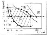
特别适用于本发明的方法的粉末材料是一种容易流化的材料,该材料的颗粒具有球状凸形的形状,具有的形状系数(Ferret比)十分接近于1,典型地为0.5至2的范围内,且尺寸——例如由中值粒径D50表示——典型地在15微米至500微米的范围内。此材料也可以具有单峰或者多峰的颗粒尺寸分布。还可以包括不同化学成分和/或密度的材料的混合物。利用Geldart在1973年提出的根据粉末的流化能力将粉末分类的表示法,即通过用下述一个点来表示材料,该点的X坐标是材料平均尺寸dp的对数而Y坐标是材料的平均密度ρs和流化气体的密度ρg之间的差值的对数,可以表明本发明的方法尤其良好地适用于在图1所示的阴影区域内所属的材料,该阴影区域粗略地相当于一个具有以下十个顶点的多边形:L(10;5)、M(100;4)、N(300;2)、O(500;1)、P(500;0.15)、Q(100;0.15)、R(60;0.2)、S(30;0.5)、T(20;1)、U(15;1),其中X坐标为括号中左侧的对应于以μm表示的颗粒尺寸的数值的对数,且Y坐标为括号中右侧的对应于以kg/dm3表示的密度的差值的数值的对数。由于在实践中很少出现密度小于1的颗粒,因此本发明的方法最适用的粉末的范围可以是如多边形LMNOU所限定的范围,即由以下不等式限制的区域:A powder material particularly suitable for use in the process of the invention is a readily fluidizable material whose particles have a spherical-convex shape with a shape factor (Ferret ratio) very close to 1, typically 0.5 to 2 range, and the size—such as represented by the median particle diameter D50—is typically in the range of 15 microns to 500 microns. The material may also have a unimodal or multimodal particle size distribution. Mixtures of materials of different chemical composition and/or density may also be included. Using the notation proposed by Geldart in 1973 to classify powders according to their fluidization ability, that is, by representing the material by a point whose X coordinate is the logarithm of the average size dp of the material and the Y coordinate is the material The logarithm of the difference between the average density ρs of the fluidization gas and the density ρg of the fluidization gas, it can be shown that the method according to the invention is particularly well suited for materials belonging to the shaded area shown in Figure 1, which is roughly Earth is equivalent to a polygon with the following ten vertices: L(10;5), M(100;4), N(300;2), O(500;1), P(500;0.15), Q(100 ; 0.15), R(60; 0.2), S(30; 0.5), T(20; 1), U(15; 1), where the X coordinates on the left side of the brackets correspond to the particle size expressed in μm The logarithm of the value and the Y coordinate is the logarithm of the value corresponding to the difference in density expressed in kg/dm3 to the right in parentheses. Since particles with a density less than 1 rarely occur in practice, the range of the most suitable powder for the method of the present invention can be the range defined by the polygon LMNOU, i.e. the area limited by the following inequalities:
a)Y≥0a) Y≥0
b)Y+3.969X-4.668≥0b) Y+3.969X-4.668≥0
c)Y+0.097X-0.796≤0c) Y+0.097X-0.796≤0
d)Y+0.631X-1.864≤0d) Y+0.631X-1.864≤0
e)Y+1.357X-3.662≤0e) Y+1.357X-3.662≤0
其中X=log10(dp),dp以微米表示并且其中Y=log10(ρs-ρg),ρs和ρg以kg/dm3表示。where X=log10 (dp ), dp is expressed in microns and where Y=log10 (ρs −ρg ), ρs and ρg are expressed in kg/dm3 .
容易流化的粉末具有的特征为:Easily fluidizable powders are characterized by:
●散式流化,其当空气速度明显大于最小流化速度时导致该床强烈膨胀,同时流化速度增加并出现鼓泡;Bulk fluidization, which causes a strong expansion of the bed when the air velocity is significantly greater than the minimum fluidization velocity, with simultaneous increase in fluidization velocity and bubbling;
●当停止流化时的缓慢脱气:这些粉末长时间保持流动;● Slow degassing when fluidization is stopped: these powders remain fluid for a long time;
●在排空料斗的过程中熔融体(fusage)的趋势,即穿过闭塞器的流体型流动。用来通过电解生产铝的氧化铝属于这一范畴。• Tendency of the fusage, ie fluid-like flow through the obturator, during emptying of the hopper. Alumina, which is used to produce aluminum by electrolysis, falls into this category.
为了表征容易流化的粉末的流化状态,一层所述粉末置于一个在与立式圆筒相当的柱之内的水平多孔壁上,我们在下文将该柱称为“流化柱”。使得气体向上穿过所述层循环,使得该气体的上升速度逐渐增加。在实践中,气流速度实际上是变化的。如此可以观察到以下连续的现象:To characterize the fluidization state of readily fluidizable powders, a layer of said powder is placed on a horizontal porous wall within a column comparable to a vertical cylinder, which we hereinafter refer to as a "fluidization column" . The gas is circulated upwards through the layer such that the rate of ascent of the gas gradually increases. In practice, the air velocity actually varies. In this way the following successive phenomena can be observed:
●对于最低速度,固体颗粒的层保持在格网上没有可见运动。如果速度进一步增加,可以观察到颗粒振动。• For the lowest velocity, the layer of solid particles remains on the grid with no visible motion. If the velocity is increased further, particle vibrations can be observed.
●从速度Umf(最小流化速度)开始,将可察觉到所述层的膨胀:以此方式实现颗粒的床在固定状态和流化状态之间的转换。在下文中,我们会将气体的使能够获得流化状态的上升速度称为流化速度。• Starting from the velocity Umf (minimum fluidization velocity), an expansion of the layer will be perceptible: in this way the transition of the bed of particles between the stationary and fluidized state is achieved. Hereinafter, we will refer to the rising velocity of the gas that enables the fluidized state to be referred to as the fluidization velocity.
●通过又进一步增大气体向上的速度,所述床继续膨胀:然后则可以描述流化状态。颗粒是相互独立的。它们进行低振幅的无序运动。没有观察到与流体相关的整体平移运动。所述床的上表面基本是清晰和水平的。该床与流体相当。• By increasing the gas velocity upwards still further, the bed continues to expand: the fluidized state can then be described. Particles are independent of each other. They make low-amplitude, chaotic movements. No bulk translational motion associated with the fluid was observed. The upper surface of the bed is substantially clear and level. The bed is comparable to a fluid.
●从气体的某一上升速度开始,在该床中出现不均匀性发生鼓泡现象(在流化床中出现多个空腔,这些空腔逐渐变大、聚结并且上升至表面)。此时流体表面的外观如沸腾液体。此为鼓泡流化状态。- Starting from a certain rising velocity of the gas, inhomogeneity occurs in the bed bubbling (cavities appear in the fluidized bed which gradually become larger, coalesce and rise to the surface). At this point the surface of the fluid will look like a boiling liquid. This is the state of bubbling fluidization.
●如果气体速度又进一步增加,形状变得不规则的所述泡逐渐增大尺寸和数量,将越来越多的固体颗粒拖入它们的尾流中:此为湍流流化状态;If the gas velocity is increased further, said bubbles, which become irregular in shape, gradually increase in size and number, dragging more and more solid particles into their wake: this is the state of turbulent fluidization;
●在某一被称为颗粒最终自由下落速度的速度以上,被气流驱动的颗粒脱离悬浮:此为夹带现象(
让我们回到低流化速度,其支配在风道的上管道中必须盛行的条件。根据本发明,基准流化速度预先是以经验确定的,或者半经验确定的,等于与最大空隙率对应的气体流化的平均速度。这可以例如利用如之前所述的流化柱来进行。Let's return to the low fluidization velocity, which governs the conditions that must prevail in the upper duct of the duct. According to the present invention, the reference fluidization velocity is empirically determined in advance, or determined semi-empirically, equal to the average velocity of gas fluidization corresponding to the maximum void ratio. This can be done, for example, using a fluidization column as described before.
空隙率与悬浮物的表观密度直接相关。它被限定为颗粒的表观密度与悬浮物的密度之间的差值,被表示为与颗粒的表观密度相比的百分比。换句话说,空隙率εLF由以下关系式确定:The void ratio is directly related to the apparent density of the suspended matter. It is defined as the difference between the apparent density of the particles and the density of the suspended matter, expressed as a percentage compared to the apparent density of the particles. In other words, the void fraction εLF is determined by the following relationship:
其中ρs为颗粒的表观密度并且其中悬浮物的密度ρLF通过以下关系式得出:whereρs is the apparent density of the particles and where the densityρLF of the suspended matter is given by the following relation:

对于给定的悬浮物,质量mp是不变的,并且柱的截面S是不变的,空隙率主要取决于在所述柱中流化床所占据的高度hLF。因此最大的空隙率对应于悬浮物的最小表观密度。For a given suspension, the mass mp is constant, and the section S of the column is constant, the porosity depends mainly on the height hLF occupied by the fluidized bed in said column. Thus the largest void fraction corresponds to the smallest apparent density of suspended matter.
图2示出了一个实施例,在该实施例中根据上升气体速度Uf在流化柱中测得冶金级氧化铝的流化床的高度H;可以看到,该床的高度以及由此的该床的体积,自与最小流化速度Umf——在此接近3mm/s——相当的某一上升速度时开始明显增加,达到最大,然后自Umb值——在此为大约7mm/s,粗略对应于出现鼓泡,并且为此原因被称为“最小鼓泡速度”——时开始减小,然后到达在鼓泡流化相的其余部分中基本不变的阶段。结果以两种形式给出:菱形并且左手侧Y轴示出了作为上升速度的函数的床的高度,方形并且右手侧Y轴示出了作为流化速度的函数的空隙率。Figure 2 shows an example in which the height H of a fluidized bed of metallurgical grade alumina is measured in a fluidization column as a function of the rising gas velocityUf ; it can be seen that the height of the bed and thus The volume of the bed begins to increase significantly from a certain rate of rise corresponding to the minimum fluidization velocity Umf - here close to 3 mm/s - to a maximum and then from the value of Umb - here about 7 mm /s, roughly corresponding to the onset of bubbling, and for this reason referred to as the "minimum bubbling velocity"—starts to decrease at , then reaches a stage where it remains essentially constant in the rest of the bubbling fluidized phase. The results are given in two forms: diamonds with the left-hand Y-axis showing bed height as a function of ascent velocity, and squares with the right-hand Y-axis showing void fraction as a function of fluidization velocity.
图3示出了与图2相同的结果,但是以作为流化速度的函数的表观密度来示出。可以看到,在最小值附近,曲线的形状是平的,虽然在所述最小值的两侧轻微不对称。这使能够限定一个表观密度变化很小并且接近该最小值的区域。第一区域——其与最大比最小表观密度的1.025倍大的表观密度相对应——由在0.8Umb至1.5Umb的范围内的流化速度确定。一个进一步限制的区域——其与最大等于最小表观密度的1.012倍的表观密度相对应——由在最小鼓泡速度Umb的0.9至1.3倍的范围内的流化速度确定。Figure 3 shows the same results as Figure 2, but in apparent density as a function of fluidization velocity. It can be seen that around the minimum, the shape of the curve is flat, although slightly asymmetrical on either side of said minimum. This makes it possible to define a region in which the variation in apparent density is small and close to the minimum. The first region - which corresponds to an apparent density whose maximum is greater than 1.025 times the minimum apparent density - is determined by a fluidization velocity in the range of 0.8 Umb to 1.5 Umb . A further restricted region—which corresponds to an apparent density at most equal to 1.012 times the minimum apparent density—is determined by fluidization velocities in the range of 0.9 to 1.3 times the minimum bubbling velocity Umb .
这些在膨胀的“静态”床上观察到的现象,被转置到风道中基本水平运动方式的超浓床。即,根据本发明,为了获得粉末材料通过潜流化的最佳传输,施加一流化压力,使得在上管道中形成与最小鼓泡速度接近的流化速度,与流化床的表观密度的最低值相对应,此时假定该最小鼓泡速度独立于在风道中的流化床的整体水平运动。These phenomena, observed on an expanded "static" bed, are transposed to super-concentrated beds that move substantially horizontally in ducts. That is, according to the present invention, in order to obtain the optimum transport of the powder material by submerged fluidization, the fluidization pressure is applied such that a fluidization velocity close to the minimum bubbling velocity is formed in the upper duct, which corresponds to the minimum apparent density of the fluidized bed values corresponding to , when it is assumed that the minimum bubbling velocity is independent of the overall horizontal motion of the fluidized bed in the duct.
根据本发明,提供了在一膨胀的“静态”床上所限定的一定值范围内的流化速度,例如在简单流化柱所观察到的,而没有任何需要来涉及风道的几何形状。在悬浮物并不进行任何整体水平移动意义上,所述床被称为“静态”的。基准流化速度,其与空隙率最大时的气体的流化速度相等,被称为最小鼓泡速度。它主要与材料的物理性能相关并且并不取决于膨胀床的容器的几何特征。如我们已看到的,所述速度范围与其中空隙率变化很小的范围相对应,它等于或者接近于最小值。申请人注意到这些条件对于在风道内获得活塞型流动是最佳的。According to the present invention, fluidization velocities are provided within a range of values defined by an expanded "static" bed, such as observed in simple fluidization columns, without any need to refer to the geometry of the duct. The bed is said to be "static" in the sense that the suspended matter does not undergo any bulk horizontal movement. The reference fluidization velocity, which is equal to the fluidization velocity of the gas at which the void fraction is maximum, is called the minimum bubbling velocity. It is mainly related to the physical properties of the material and does not depend on the geometrical characteristics of the container of the expanded bed. As we have seen, said velocity range corresponds to a range in which the void fraction varies little, being equal to or close to a minimum. The Applicant noted that these conditions are optimal for obtaining a plug-type flow in the duct.
如此可以提供一个明确的流化速度而不依赖于风道的准确几何构型。然而,只有在风道已经被设计为在可能被悬浮物占据的上管道的任意点处都存在粉末材料的潜流化的情况下,本发明的方法才可以给出良好的结果。This provides a well-defined fluidization velocity independent of the exact geometry of the duct. However, the method of the invention can only give good results if the air duct has been designed so that there is subfluidization of the powder material at any point of the upper duct that may be occupied by suspended solids.
上管道中的气体流化速度为在上管道中的气体速度的上升竖直分量。它可以通过任意适当的方式测得,例如通过使用已知透过性的网格和热线风速计。在如下所述的优选实施方案中,它可以通过测量被注入下管道的气体流速和通过将其值除以将下管道与上管道分隔的多孔壁的表面来更简单地限定。The gas fluidization velocity in the upper duct is the rising vertical component of the gas velocity in the upper duct. It can be measured by any suitable means, for example by using a grid of known permeability and a hot wire anemometer. In a preferred embodiment as described below, it can be more simply defined by measuring the flow rate of the gas injected into the lower conduit and by dividing its value by the surface of the porous wall separating the lower conduit from the upper conduit.
风道有利地被分成相互连接的多个区段,每一区段包括一平衡柱并且在所述多个区段中的每一个区段中上管道的上部区域被压力气泡占据,如同在EP 1 086 035中。以此方式,通过适宜地限定这些区段的几何形状,可以施加与在流化柱中的“静态”膨胀床的流化条件基本相当的流化条件,即,在悬浮物的高度处施加一个基本竖直的气体速度,该气体速度的水平分量只有在下管道中以及在压力气泡中,尤其是在平衡柱附近,才变得明显不等于零。The air duct is advantageously divided into interconnected sections, each section comprising a balancing column and in each of said sections the upper region of the upper duct is occupied by pressure bubbles, as in
以此方式,气体仅被用来使得悬浮物膨胀而不水平地夹带颗粒,气体直接移动至气泡中并且通过平衡柱去除。颗粒的水平运动于是仅由供应系统以及牵拉(sous-tirage)产生,平衡柱用于确保逐个区段地加载整个风道。In this way, gas is only used to expand the suspension and not entrain particles horizontally, the gas moves directly into the bubbles and is removed through the balance column. The horizontal movement of the particles is then only produced by the supply system and the sous-tirage, the balancing columns are used to ensure that the entire duct is loaded section by section.
在这些条件下,悬浮物的表现如同液体并且与传输固体颗粒相关的压力损耗非常小。它极大地取决于颗粒的动力学以及悬浮物在上管道内壁上的摩擦状况。但是它基本上与流化条件无关。以此方式,可以获得粉末材料的特别大的质量吞吐量而不过度消耗流化气体。例如,对于诸如冶金级的氧化铝等材料,大约10mm/s的流化速度可以产生或者甚至超过大约70kg/m2s的质量吞吐量,而这些流量使用常规的气动传输将需要大约15m/s的气体速度,意味着大了150倍的气体消耗。Under these conditions, the suspension behaves like a liquid and the pressure loss associated with transporting solid particles is very small. It greatly depends on the dynamics of the particles and the frictional conditions of the suspension on the inner wall of the upper pipe. But it basically has nothing to do with fluidization conditions. In this way, a particularly large mass throughput of powder material can be obtained without excessive consumption of fluidizing gas. For example, for a material such as metallurgical grade alumina, a fluidization velocity of about 10 mm/s can produce or even exceed a mass throughput of about 70 kg/m2 s, whereas these flows would require about 15 m/s using conventional pneumatic transport Gas velocity means 150 times greater gas consumption.
对于每一区段,与所述区段相关的上管道的长度、平衡柱的高度和截面有利地被限定为:考虑到要传输的材料的流动,上管道的内部处于与鼓泡开始时的流化条件接近的流化条件并且所述柱的内部处于湍流态条件。在柱的出口处的气体速度必须不超过某一界限,超过该界限则细粒的夹带将导致粉末材料的不可接受的损耗。此外,两个相邻区段的下管道部分互相连接,但是在其上施加某一压力损失——典型地利用隔膜,以使得在每一区段中,上管道中的气压对应于一个流化速度保持在所述范围内所相关的压力,所述范围即在最小鼓泡速度的0.8至1.5倍(优选地为0.9至1.3倍)。For each section, the length of the upper duct, the height and the cross-section of the balancing column associated with said section are advantageously defined such that, taking into account the flow of the material to be transported, the interior of the upper duct is at the same position as at the beginning of the bubbling. Fluidization conditions are close to fluidization conditions and the interior of the column is in turbulent conditions. The gas velocity at the outlet of the column must not exceed a limit beyond which entrainment of fines would lead to an unacceptable loss of powder material. In addition, the lower duct sections of two adjacent sections are interconnected, but a certain pressure loss is imposed across them - typically with diaphragms, so that in each section the air pressure in the upper duct corresponds to a fluidized The pressure associated with the velocity being maintained within the range, ie between 0.8 and 1.5 times (preferably 0.9 and 1.3 times) the minimum sparging velocity.
申请人注意到通过提供一种与对应于悬浮物最小表观体积密度的流化模式相接近的流化模式,不仅粉末可以以高速传输,而且特别地,在风道中可以建立活塞式流动,即这样一种流动,其中,忽视摩擦的影响,进入截面的任何颗粒都受到一相同的轴向速度,以使得每一悬浮物截面在供应区域和待供应区域之间保持颗粒在尺寸和密度方面的相同分布。这是一个保持分布直方图的问题,而不是空间分布的问题,因为重力可以沿着该路径在任何地方介入,重量最大并且因此最致密和/或最大的颗粒趋向于聚集在下部并且由此产生的结果可能是该截面并不保持其初始的均匀性。尽管如此但确实是没有偏析,即在风道内的任意位置,没有具有一特定颗粒尺寸和密度的颗粒的聚集。该结果对于涉及多峰粉末或者具有不同性能的粉末的混合物在较远距离上传输的许多应用是重要的,其在下文实施例中描述。The applicant noticed that by providing a fluidization pattern close to that corresponding to the minimum apparent bulk density of the suspension, not only can the powder be transported at high speed, but in particular a plug flow can be established in the air duct, i.e. A flow in which, neglecting the effects of friction, any particles entering a section are subjected to an identical axial velocity so that each suspension section maintains the particle size and density uniformity between the supply area and the area to be supplied same distribution. This is a matter of maintaining a histogram of the distribution, not a spatial distribution, since gravity can intervene anywhere along the path, the heaviest and thus densest and/or largest particles tend to gather in the lower part and thus The result may be that the section does not retain its original uniformity. Nonetheless, there is no segregation, ie no aggregation of particles of a particular particle size and density at any point within the duct. This result is important for many applications involving the transport of multimodal powders or mixtures of powders with different properties over longer distances, which are described in the Examples below.
如我们已经看到,基准流化速度对应于最小鼓泡速度,该最小鼓泡速度与粉末材料的物理性能有关。它可以例如通过使用流化柱以经验确定。它也可以利用来自文献的公式以及在重新设定某些常数之后半经验地确定。As we have seen, the reference fluidization velocity corresponds to the minimum bubbling velocity which is related to the physical properties of the powder material. It can be determined empirically, for example by using a fluidization column. It can also be determined semi-empirically using formulas from literature and after resetting some constants.
例如,可以使用由Abrahamsen等人提出的经验公式(“粉末技术”(Powder Technology),第26卷,第1期,1980年5-6月),该公式根据颗粒的特征尺寸(dP,以米表示)、以及气体的密度ρg(以m3/kg为单位)和动态粘度μg(以Pa.s为单位),给出了最小鼓泡速度,For example, the empirical formula proposed by Abrahamsen et al. (Powder Technology, Vol. 26, No. 1, May-June 1980), which is based on the characteristic size of the particles (dP , in expressed in meters), and the density ρg (in m3 /kg) and the dynamic viscosity μg (in Pa.s) of the gas, give the minimum bubbling velocity,
申请人注意到,对于冶金级氧化铝,利用此公式,在将中间粒径D90作为颗粒的特征尺寸dp的条件下,可以高准确度地估算出最小鼓泡速度Umb(以m/s表示)。The applicant noticed that, for metallurgical grade alumina, using thisformula , the minimum bubbling velocity Umb (in m/s express).
此外,申请人注意到,平衡柱优选必须被设计为使得对于在上管道中的所述流化,在该柱中到达湍流流化状态,其中该床由来去迅速的气相和固相的小单元组成并且其中难以区分该床的表面,该床的底部比上部显著更致密。以此方式设计,平衡柱的表现如同与之相关的风道区段的加载源。换言之,而且为了使悬浮物继续与液体行为相似,它们的作用就像都沿所述风道安装的水塔。在该柱的出口的气体速度必须另外被限制,以避免夹带过多的细颗粒到该装置之外。此外,可以将一个大截面的膨胀容器置于所述柱之上,以降低该速度以及回收一部分所夹带的细颗粒。Furthermore, the Applicant notes that the balance column must preferably be designed such that for said fluidization in the upper conduit, a turbulent fluidization regime is reached in the column, where the bed consists of small cells of gas and solid phases that come and go rapidly composition and where it is difficult to distinguish the surface of the bed, the bottom of the bed is significantly denser than the upper part. Designed in this way, the balancing column behaves like a source of loading for the duct section it is associated with. In other words, and in order for the suspended matter to continue to behave like a liquid, they act like water towers both installed along said air duct. The gas velocity at the outlet of the column must additionally be limited to avoid entraining too much fine particles out of the unit. Additionally, an expansion vessel of large cross-section can be placed above the column to reduce the velocity and recover a portion of the entrained fines.
图1示出了由Geldart所做的分类(Powder Technology,第7卷,第5期,1973年5月,285-292),其非常广泛地用于根据粉末的流化能力将粉末分类。它根据颗粒密度和尺寸将粉末分类:A类表示容易流化的粉末,称为“熔融”,B类表示相对容易流化的粉末,称为砂质粉末,C类表示只可以困难地流化的细的、粘性粉末,以及D类表示具有不规则流化的粒状粉末。Figure 1 shows the classification made by Geldart (Powder Technology, Vol. 7, No. 5, May 1973, 285-292), which is very widely used to classify powders according to their fluidization capabilities. It classifies powders according to particle density and size: Class A indicates powders that fluidize easily and is called "melted", category B indicates powders that fluidize relatively easily and is called sandy powder, and category C indicates powders that can only fluidize with difficulty A fine, cohesive powder of type D, and a granular powder with irregular fluidization.
阴影区域对应于A类、一小部分C类以及一小部分B类——都接近于A类,这意味着特别适用于根据本发明的方法传输的粉末材料是任意种类的A类熔融粉末、较大的C类所谓粘性粉末——材料越致密,最小公认尺寸越小——以及B类所谓砂质粉末中较细的粉末材料——材料越致密,最大公认尺寸越小。The shaded area corresponds to class A, a small part of class C and a small part of class B - all close to class A, which means that powder materials particularly suitable for transfer according to the method of the present invention are any kind of molten powder of class A, The larger class C so-called cohesive powders - the denser the material, the smaller the smallest recognized size - and the finer powder materials in the class B so-called sandy powders - the denser the material, the smaller the largest recognized size.
对于本专利来说,由实验观测值所得到的该阴影区域,已经用多边形LMNOPQRSTU表示,在实践中被限为由一组不等式所限定的多边形LMNOU,但是可以理解的是,这些边界并不是它们的数学公式会使得人们所认为的那样严格的边界,并且该组不等式必须被认为是也表示了由此所限定的区域的邻近附近。For the purposes of this patent, this shaded area, obtained from experimental observations, has been denoted by the polygon LMNOPQRSTU, and in practice is limited to the polygon LMNOU bounded by a set of inequalities, but it is understood that these boundaries are not their The mathematical formulation of would make as tight a boundary as one would think, and the set of inequalities must be considered to also express the immediate vicinity of the region thus bounded.
图2和3,如上文所提到的,示出了对于冶金级氧化铝——即用来通过熔融电解来生产铝的氧化铝——所获得结果。Figures 2 and 3, as mentioned above, show the results obtained for metallurgical grade alumina, ie alumina used to produce aluminum by molten electrolysis.
图4是该装置的示意性竖直截面图,在此包括将贮存装置连接至一个去除机构的水平风道,该风道可表示主输送器或二级输送器的一部分。Figure 4 is a schematic vertical cross-sectional view of the device, here including a horizontal duct connecting the storage unit to a removal mechanism, which duct may represent a part of a primary conveyor or a secondary conveyor.
图5是一个示意图,示出了在根据本发明的方法的框架内所使用的以及被分成多个区段的风道。FIG. 5 is a schematic diagram showing the air duct used within the framework of the method according to the invention and divided into sections.
图6是一个示意图,示出了在根据本发明的方法的框架内所使用的一个先导风道,用来限定使可获得无偏析传输的最佳条件。FIG. 6 is a schematic diagram showing a pilot duct used within the framework of the method according to the invention to define the optimum conditions for obtaining segregation-free transport.
图7示出了在图6的先导上进行示踪剂配料的结果。FIG. 7 shows the results of tracer dosing on the lead of FIG. 6 .
实施例Example
实施例1(图4和5)Example 1 (Figures 4 and 5)
在图4所示的装置包括:高架的贮存罐1,用于所要传输的材料,其通过管路2连接至流化风道式或气动滑板式的输送器3;平衡柱4.1和4.2;以及自输送器的去除机构9,该去除机构利用受控的配料系统10将粉末材料朝向待供应区域11输送。The device shown in Figure 4 comprises: an
该高架的贮存罐1包含处于大气压下的散装粉末材料12。该罐经由管路2在水平输送器3的其中一个末端填充。输送器3是细长的并且包括将下管道6和上管道7分隔的多孔壁5,粉末材料在上管道7中循环。The
流化气体G穿过导管8被引入下管道6,在该下管道6处气体受到流化压力pf。该气体穿过多孔壁5(也被称为织物),然后穿过将输送器的上管道7填充的粉末材料。气体通过平衡柱4.1和4.1的开放的顶端被去除。填充高度15.1和15.2与将上管道中的气体压力平衡的压头h1和h2相对应。The fluidizing gas G is introduced through the conduit 8 into the lower conduit 6 where the gas is subjected to the fluidizing pressure pf . The gas passes through the porous wall 5 (also called fabric) and then through the powder material filling the upper duct 7 of the conveyor. Gases are removed through the open top of balance columns 4.1 and 4.1. Filling heights 15.1 and 15.2 correspond to pressure heads h1 and h2 which equalize the gas pressure in the upper duct.
上管道7的上部区域被处于压力B1和B2下的气泡占据,这些气泡的体积优选地在空间上由以下限定:The upper region of the upper duct 7 is occupied by gas bubbles under pressures B1 and B2, the volume of which gas bubbles is preferably spatially defined by:
●上管道7的上部14的壁,the wall of the upper part 14 of the upper duct 7,
●扁铁50●
●平衡柱4.1和4.2的陷入部40.1和40.2●Insets 40.1 and 40.2 of balance columns 4.1 and 4.2
●以及粉末材料12的顶部水平面13。• and the top level 13 of the powder material 12 .
图4示意性示出了流化气体G如何循环、穿过织物5然后朝向屏障50两侧的平衡柱4.1和4.2移动。FIG. 4 schematically shows how the fluidizing gas G circulates, passes through the
所述材料通过整体水平运动而被致动,该整体水平运动在此通过与速度us相关的矢量用符号表示出。气体穿过多孔壁5并且以整体向上的运动溢出通过悬浮物12’。在本发明的一个优选实施方案中,风道被设计为使得气体的速度Uf在悬浮物所占据的空间的高度上是基本竖直的。The material is actuated by an overall horizontal movement, which is here symbolized by a vector related to the velocity us . The gas passes through the
风道设有一去除机构9,该去除机构将粉末材料的水平运动转换成竖直或者倾斜很大的运动,使得如果风道是主输送器,它能够供应二级输送器,或者如果风道是二级输送器,它能够供应一被集成到电解罐的上部结构中的料斗。料斗的底部装备有受控的配料系统10,使得它能够将所需量的氧化铝输入到罐中。The duct is provided with a removal mechanism 9 which converts the horizontal movement of the powdered material into a vertical or highly inclined movement so that it can supply a secondary conveyor if the duct is the main conveyor, or if the duct is a Secondary conveyor capable of supplying a hopper integrated into the superstructure of the electrolytic tank. The bottom of the hopper is equipped with a controlled
图5示出了被分成n个区段的风道,每一区段与气泡Bi(i=1至n)以及平衡柱Di(i=1至n)相关联。Fig. 5 shows an air duct divided into n sections, each section being associated with a bubble Bi (i=1 to n) and a balance column Di (i=1 to n).
在风道的末端,气泡Bn与去除机构9相关联。屏障50.n实际上是输送器的末端壁90的一部分,该末端壁位于最后一个平衡柱4.n的下游。压力传感器80,靠近风道3的末端90定位,使得它能够测量在气泡Bn内的压力,由于在每一区段中的压力损耗(相当弱,主要由于颗粒沿着壁摩擦)的积累该压力为气泡的最低压力。获知该值使能够调节流化压力pf。At the end of the air duct, the air bubbles Bn are associated with the removal mechanism 9 . The barrier 50.n is actually part of the end wall 90 of the conveyor, which is located downstream of the last balancing column 4.n. The pressure sensor 80, positioned close to the end 90 of the duct 3, makes it possible to measure the pressure inside the bubbleBn , which due to the accumulation of pressure losses (rather weak, mainly due to the friction of particles along the wall) in each section The pressure is the minimum pressure of the bubble. Knowing this value enables adjustment of the fluidization pressure pf .
两个相邻区段的下管道的部分被相互连接,但是施加有一定的压力损耗——典型地利用隔膜,使得在每一区段中上管道中的气压对应于一个流化速度保持在所述范围内所相关的压力,所述范围即在最小鼓泡速度的0.8至1.5倍(优选地为0.9至1.3倍)。Sections of the lower duct of two adjacent sections are interconnected, but with a certain pressure loss imposed - typically by means of a diaphragm, so that the gas pressure in the upper duct in each section is maintained at the given fluidization velocity corresponding to a fluidization velocity. The pressures associated therewith are within the stated range, ie 0.8 to 1.5 times (preferably 0.9 to 1.3 times) the minimum bubbling velocity.
实施例2(图6和7)——揭示一活塞流Example 2 (Figures 6 and 7) - reveals a plug flow
为了限定用于获得活塞流的最佳条件,我们使用了一个例如在图6所示的先导输送器3’。In order to define the optimum conditions for obtaining plug flow, we use a pilot conveyor 3' such as shown in Fig. 6 .
风道3’包括一个长度大约5米、且具有300mm(高度)乘160mm(宽度)的截面的上管道7’。上管道7’通过一具有给定渗透率的织物5’与下管道6’分隔。The air duct 3' comprises an upper duct 7' having a length of approximately 5 meters and a cross-section of 300 mm (height) by 160 mm (width). The upper duct 7' is separated from the lower duct 6' by a fabric 5' having a given permeability.
使用一转子流量计来读取供应下管道的空气G的总流量。测量和记录压力pf。平衡柱4’具有用于5m高度的326mm的内径,并且它降低50mm进入到风道。平衡柱4’的进入上管道7’的陷入部形成一个将上管道7’的上部区域分成两个气泡B’1和B’2的屏障。氧化铝供应柱1’具有大约6米的高度。Use a rotameter to read the total flow of air G supplied to the lower duct. Measure and record the pressure pf . The balance column 4' has an inner diameter of 326mm for a height of 5m and it is lowered 50mm into the air duct. The plunge of the balance column 4' into the upper duct 7' forms a barrier that divides the upper region of the upper duct 7' into two air bubbles B'1 and B'2. The alumina supply column 1' has a height of about 6 metres.
所要传输的材料为冶金氧化铝AR75 ALUMINIUM PECHINEY。所选择的示踪剂来自染色后的该相同的AR75粉末。它在风道中与其余的AR75是完全可混合的并且它具有与所测试的氧化铝完全相同的流动性质。配料的方法包括进行一个白度测试。它使能够准确、简单和容易地配料以非常小量的标志物,以及将此量与初始导入风道中的量进行比较。The material to be transferred is metallurgical alumina AR75 ALUMINUM PECHINEY. The selected tracer was from this same AR75 powder after dyeing. It is completely miscible in the duct with the rest of AR75 and it has exactly the same flow properties as the alumina tested. The batching method includes conducting a whiteness test. It enables accurate, simple and easy dosing of markers in very small quantities and comparison of this quantity with the quantity initially introduced into the air duct.
已知量的标志物在压力下注入(在I处)上管道7’的上部,紧跟柱1’供应固体之后。通过从位于风道的水平部分的出口处的喷嘴的中间采样来(在O处)进行准确采样(每5s)。我们已经利用染色氧化铝得出了校准曲线。这些曲线可被用来快速和简单地确定在AR75中存在的染色氧化铝的百分比。这一信息使能够确定氧化铝的滞留时间以及它如何在风道内循环。A known amount of marker is injected under pressure (at I) into the upper part of the upper conduit 7', immediately after the column 1' supply of solids. Accurate sampling (every 5 s) was done (at 0) by sampling from the middle of the nozzle located at the outlet of the horizontal section of the duct. We have developed a calibration curve using dyed alumina. These curves can be used to quickly and easily determine the percentage of dyed alumina present in AR75. This information enables the determination of the residence time of the alumina and how it circulates within the duct.
对于多种固体和气体流量进行示踪试验。图7是所观察到的结果的典型。它示出了示踪剂浓度随时间的变化,以示踪剂浓度与其初始浓度相比的百分比表示。所选择的曲线对应于42kg/s/m2的固体流量以及10mm/s的流化速度。起初(I),没有观察到示踪剂浓度的变化。在曲线的第二部分(II),可以观察到与示踪剂的通过相关的峰:相对突然的上升是活塞流的特征。所观察的延迟与示踪剂从注入点到采样点之间的物理移动相关。由于在此先导中使用的固体循环系统,示踪剂的浓度并不恢复至其初始值。示踪剂注入区域的位置以及采样区域的位置显示了在悬浮物截面已经进行了混合,即在与风道的轴线(即在颗粒的整体移动方向上)垂直的平面内的颗粒的移动。Perform tracer tests on a variety of solid and gas flows. Figure 7 is typical of the results observed. It shows the change in tracer concentration over time expressed as a percentage of the tracer concentration compared to its initial concentration. The chosen curve corresponds to a solids flow rate of 42 kg/s/m2 and a fluidization velocity of 10 mm/s. Initially (I), no change in tracer concentration was observed. In the second part (II) of the curve, a peak associated with the passage of tracer can be observed: a relatively abrupt rise is characteristic of plug flow. The observed delay is related to the physical movement of the tracer from the point of injection to the point of sampling. Due to the solid recirculation system used in this pilot, the concentration of the tracer did not return to its original value. The location of the tracer injection area as well as the location of the sampling area shows that mixing has taken place in the suspension cross-section, ie the movement of the particles in a plane perpendicular to the axis of the duct (ie in the direction of the overall movement of the particles).
实例3各种材料的各种最小鼓泡速度Various minimum bubbling speeds of various materials of example 3
对于各种粉末材料确定最小鼓泡速度:Determine the minimum bubble rate for various powder materials:
——熔炼级氧化铝——Smelting grade alumina
所测试的氧化铝是由ALUMINIUM PECHINEY以标号AR75在市场销售的氯化铝。在一流化柱中测得的最小鼓泡速度为接近7mm/s并且通过Abrahmsen的公式计算出的最小鼓泡速度为接近10mm/s。The alumina tested was aluminum chloride marketed under the designation AR75 by ALUMINUM PECHINEY. The minimum bubbling velocity measured in a fluidized column was approximately 7mm/s and calculated by Abrahmsen's formula was approximately 10mm/s.
——砂子- sand
所测试的砂子具有以下特性:The tested sand had the following properties:
○ρs=2409kg/m3○ρs =2409kg/m3
○D10=170μm○D10=170μm
○D50=302μm○D50=302μm
○D90=503μm○D90=503μm
它属于Geldart分类中的B类。将D50作为颗粒的特征尺寸,此材料接近于图1中的多边形LMNOPQRSTU的边MN。在一流化柱所测得的最小鼓泡速度非常接近于最小流化速度。它接近65mm/s。通过Abrahmsen的公式计算出的最小速度为接近75mm/s。It belongs to class B in the Geldart classification. Taking D50 as the characteristic dimension of the particles, this material is close to the side MN of the polygon LMNOPQRSTU in Fig. 1. The minimum bubbling velocity measured in a fluidization column is very close to the minimum fluidization velocity. It is close to 65mm/s. The minimum velocity calculated by Abrahmsen's formula is close to 75mm/s.
——盐--Salt
所测试的盐为氯化钠。它具有以下特征:The salt tested was sodium chloride. It has the following characteristics:
○ρs=2082kg/m3○ρs =2082kg/m3
○D10=116μm○D10=116μm
○D50=425μm○D50=425μm
○D90=761μm○D90=761μm
它也属于Geldart分类中的B类。将D50作为颗粒的特征尺寸,此材料在图1中的多边形LMNOPQRSTU之内,靠近区段MN。在一流化柱所测得的最小鼓泡速度非常接近于最小流化速度。它接近100mm/s。通过Abrahmsen的公式计算出的最小速度为接近125mm/s。It also belongs to class B in the Geldart classification. Taking D50 as the characteristic size of the particle, this material is within the polygon LMNOPQRSTU in Figure 1, close to the segment MN. The minimum bubbling velocity measured in a fluidization column is very close to the minimum fluidization velocity. It is close to 100mm/s. The minimum velocity calculated by Abrahmsen's formula is close to 125mm/s.
在钠和氯的制造过程中氯化钠也被输送至供应电解罐的范围内,利用潜流化并且以诸如所要求保护的流化速度运行的该种输送器可以最终是特别有用的。Where sodium chloride is also conveyed to the extent that the electrolytic tanks are supplied during the manufacture of sodium and chlorine, such a conveyer utilizing submerged fluidization and operating at fluidization speeds such as claimed may ultimately be particularly useful.
——三种人造水泥:- Three types of man-made cement:
这些水泥是典型地包含硅石、氧化铝和碳酸钙的各种矿物的混合物,该混合物在通过机械方式被缩小成粉末时与水接触。测试了三个品种。它们具有以下特征:These cements are mixtures of various minerals, typically including silica, alumina and calcium carbonate, which contact water while being mechanically reduced to a powder. Three varieties were tested. They have the following characteristics:
1)粗水泥:ρs=2780kg/m31) Coarse cement: ρs =2780kg/m3
D10=2.0μm;D50=15.3μm;D90=94.7μmD10=2.0μm; D50=15.3μm; D90=94.7μm
该材料属于C类。The material belongs to class C.
2)细水泥:ρs=3090kg/m32) Fine cement: ρs =3090kg/m3
D10=3.3μm;D50=18.2μm;D90=47.1μmD10=3.3μm; D50=18.2μm; D90=47.1μm
该材料属于A类和C类之间的边缘区域。This material belongs to the marginal area between Class A and Class C.
3)特细水泥:ρs=3130kg/m33) Extra fine cement: ρs =3130kg/m3
D10=2.2μm;D50=11.6μm;D90=28.5μmD10=2.2μm; D50=11.6μm; D90=28.5μm
该材料属于C类。The material belongs to class C.
通过在一流化柱上进行所述试验确定最小流化速度,该流化速度类似于对于氧化铝所获得的流化速度,它们分别为接近于3.3mm/s、3mm/s和4.3mm/s。Minimum fluidization velocities were determined by carrying out said experiments on a fluidization column, which were similar to those obtained for alumina, which were approximately 3.3mm/s, 3mm/s and 4.3mm/s respectively .
在一个诸如在前述实施例中所描述类型的且如图6所示的先导风道中进行的试验,已经显示自流化气体的速度大约28-30mm/s时,这三种类型的粉末开始在水平过道上溢出。注意到对于此类型的材料,应用dp=D90时的Abrahmsen的公式,并不能够获得对于流化速度而言目标范围值的满意估计。Tests carried out in a pilot duct such as that described in the previous examples and shown in Figure 6 have shown that the three types of powders start to level at Overflow in the aisle. Note that applying Abrahmsen's formula fordp = D90 does not allow a satisfactory estimate of the target range of values for the fluidization velocity to be obtained for this type of material.
Claims (10)
Applications Claiming Priority (3)
| Application Number | Priority Date | Filing Date | Title |
|---|---|---|---|
| FR0705227 | 2007-07-19 | ||
| FR0705227AFR2918975B1 (en) | 2007-07-19 | 2007-07-19 | PROCESS FOR CONVEYING WITHOUT SEGREGATION OF PULVERULENT MATERIALS |
| PCT/FR2008/000903WO2009010667A2 (en) | 2007-07-19 | 2008-06-26 | Method for transporting powdery materials without segregation |
Publications (1)
| Publication Number | Publication Date |
|---|---|
| CN101754918Atrue CN101754918A (en) | 2010-06-23 |
Family
ID=39063739
Family Applications (1)
| Application Number | Title | Priority Date | Filing Date |
|---|---|---|---|
| CN200880025040APendingCN101754918A (en) | 2007-07-19 | 2008-06-26 | Method for transporting powder material without segregation |
Country Status (12)
| Country | Link |
|---|---|
| US (1) | US8425159B2 (en) |
| EP (1) | EP2185450B1 (en) |
| JP (1) | JP2010533632A (en) |
| CN (1) | CN101754918A (en) |
| AR (1) | AR067601A1 (en) |
| AU (1) | AU2008277512B2 (en) |
| BR (1) | BRPI0814084A2 (en) |
| CA (1) | CA2695188C (en) |
| FR (1) | FR2918975B1 (en) |
| MY (1) | MY152216A (en) |
| RU (1) | RU2487829C2 (en) |
| WO (1) | WO2009010667A2 (en) |
Cited By (4)
| Publication number | Priority date | Publication date | Assignee | Title |
|---|---|---|---|---|
| CN103269961A (en)* | 2010-10-28 | 2013-08-28 | 阿尔斯通技术有限公司 | Valves used to control the flow of material leaving the heat exchanger |
| US9557115B2 (en) | 2010-10-28 | 2017-01-31 | General Electric Technology Gmbh | Orifice plate for controlling solids flow, methods of use thereof and articles comprising the same |
| CN109081146A (en)* | 2018-09-05 | 2018-12-25 | 宿松县东全米业有限公司 | A kind of corn feeding dust-extraction unit |
| CN114007764A (en)* | 2019-06-11 | 2022-02-01 | 系统陶瓷股份公司 | Dispensing equipment for granular materials |
Families Citing this family (8)
| Publication number | Priority date | Publication date | Assignee | Title |
|---|---|---|---|---|
| US8764350B2 (en)† | 2008-06-05 | 2014-07-01 | Alstom Technology Ltd | Conveyor for transporting powder, and a method for conveying powder |
| FR2952363B1 (en)* | 2009-11-09 | 2011-11-11 | Alcan Int Ltd | POTENTIALLY FLUIDIZING DEVICE FOR CONVEYING PULVERULENT MATERIALS IN HYPERDENSE BED |
| CN102466104B (en)* | 2010-11-08 | 2015-08-26 | 通用电气公司 | Pipeline and delivery method |
| EP2652450A4 (en)* | 2010-12-15 | 2018-01-03 | Anubis Manufacturing Consultants Corp. | System for and method of measuring flow of a powder |
| US20140270998A1 (en)* | 2013-03-14 | 2014-09-18 | Babcock Power Services, Inc. | Pneumatic conveyor fabric frames and mounts |
| CN104555434A (en)* | 2013-10-20 | 2015-04-29 | 宁夏嘉翔自控技术有限公司 | Pneumatic conveying system for raw cement materials |
| CN104692120A (en)* | 2015-02-10 | 2015-06-10 | 云南云铝涌鑫铝业有限公司 | Pneumatic chute device |
| US11708225B2 (en)* | 2019-04-04 | 2023-07-25 | Reel Alesa Ag | Precision flow feeding device |
Family Cites Families (10)
| Publication number | Priority date | Publication date | Assignee | Title |
|---|---|---|---|---|
| US3268264A (en)* | 1964-08-13 | 1966-08-23 | Arthur M Squires | Apparatus and method for conveying dry pulverulent solid in liquidlike state |
| US4016053A (en)* | 1975-10-01 | 1977-04-05 | Kaiser Aluminum & Chemical Corporation | Feeding particulate matter |
| FR2534891B1 (en)* | 1982-10-22 | 1987-01-09 | Pechiney Aluminium | CLOSED POTENTIAL FLUIDIZATION DEVICE FOR HORIZONTAL CONTROL OF POWDER MATERIALS |
| FR2562878B2 (en) | 1984-04-12 | 1989-06-30 | Pechiney Aluminium | CLOSED POTENTIAL FLUIDIZATION DEVICE FOR HORIZONTAL CONVEYANCE IN DENSE BED OF POWDER MATERIALS |
| FR2575734B1 (en)* | 1985-01-08 | 1989-11-17 | Pechiney Aluminium | REGULATED FLOW DISPENSING DEVICE OF A FLUIDISABLE POWDER MATERIAL |
| FR2671061A1 (en)* | 1990-12-26 | 1992-07-03 | Pechiney Aluminium | DEVICE FOR SEPARATING FLUIDIZED BED MATERIAL AND COLDING DETECTION. |
| FR2778393B1 (en)* | 1998-05-11 | 2000-06-16 | Pechiney Aluminium | PROCESS FOR THE CONVEYANCE OF POWDER MATERIALS IN A HYPERDENSE BED AND POTENTIAL FLUIDIZATION DEVICE FOR IMPLEMENTING THE SAME |
| FR2779136B1 (en)* | 1998-06-02 | 2000-07-28 | Pechiney Aluminium | PROCESS FOR CONVEYING HYDROPENSIVE PHASE OF POWDERY MATERIALS APPLICABLE TO BYPASSING OBSTACLES |
| RU2144898C1 (en)* | 1998-11-11 | 2000-01-27 | Всероссийский научно-исследовательский институт механизации сельского хозяйства | Loose material ventilation and transportation device |
| FR2831528B1 (en)* | 2001-10-26 | 2004-01-16 | Pechiney Aluminium | POWDER MATERIAL DISTRIBUTION SYSTEM WITH CONTROLLED WEIGHTS |
- 2007
- 2007-07-19FRFR0705227Apatent/FR2918975B1/ennot_activeExpired - Fee Related
- 2008
- 2008-06-26WOPCT/FR2008/000903patent/WO2009010667A2/enactiveApplication Filing
- 2008-06-26EPEP08826336.3Apatent/EP2185450B1/enactiveActive
- 2008-06-26BRBRPI0814084-7A2Apatent/BRPI0814084A2/ennot_activeIP Right Cessation
- 2008-06-26MYMYPI20100245patent/MY152216A/enunknown
- 2008-06-26CACA2695188Apatent/CA2695188C/enactiveActive
- 2008-06-26JPJP2010516533Apatent/JP2010533632A/ennot_activeAbandoned
- 2008-06-26RURU2010105852/11Apatent/RU2487829C2/enactive
- 2008-06-26CNCN200880025040Apatent/CN101754918A/enactivePending
- 2008-06-26USUS12/669,499patent/US8425159B2/enactiveActive
- 2008-06-26AUAU2008277512Apatent/AU2008277512B2/enactiveActive
- 2008-07-18ARARP080103107Apatent/AR067601A1/enactiveIP Right Grant
Cited By (7)
| Publication number | Priority date | Publication date | Assignee | Title |
|---|---|---|---|---|
| CN103269961A (en)* | 2010-10-28 | 2013-08-28 | 阿尔斯通技术有限公司 | Valves used to control the flow of material leaving the heat exchanger |
| CN103269961B (en)* | 2010-10-28 | 2016-06-15 | 阿尔斯通技术有限公司 | Valves used to control the flow of material leaving the heat exchanger |
| US9557115B2 (en) | 2010-10-28 | 2017-01-31 | General Electric Technology Gmbh | Orifice plate for controlling solids flow, methods of use thereof and articles comprising the same |
| US9617087B2 (en) | 2010-10-28 | 2017-04-11 | General Electric Technology Gmbh | Control valve and control valve system for controlling solids flow, methods of manufacture thereof and articles comprising the same |
| CN109081146A (en)* | 2018-09-05 | 2018-12-25 | 宿松县东全米业有限公司 | A kind of corn feeding dust-extraction unit |
| CN114007764A (en)* | 2019-06-11 | 2022-02-01 | 系统陶瓷股份公司 | Dispensing equipment for granular materials |
| CN114007764B (en)* | 2019-06-11 | 2024-03-26 | 系统陶瓷股份公司 | Dispensing equipment for granular materials |
Also Published As
| Publication number | Publication date |
|---|---|
| BRPI0814084A2 (en) | 2015-02-03 |
| RU2010105852A (en) | 2011-08-27 |
| US8425159B2 (en) | 2013-04-23 |
| WO2009010667A8 (en) | 2010-05-06 |
| US20100189518A1 (en) | 2010-07-29 |
| JP2010533632A (en) | 2010-10-28 |
| EP2185450B1 (en) | 2013-04-10 |
| FR2918975A1 (en) | 2009-01-23 |
| AU2008277512B2 (en) | 2013-06-27 |
| MY152216A (en) | 2014-08-29 |
| RU2487829C2 (en) | 2013-07-20 |
| EP2185450A2 (en) | 2010-05-19 |
| WO2009010667A3 (en) | 2009-03-05 |
| AU2008277512A1 (en) | 2009-01-22 |
| CA2695188A1 (en) | 2009-01-22 |
| FR2918975B1 (en) | 2009-11-20 |
| AR067601A1 (en) | 2009-10-14 |
| WO2009010667A2 (en) | 2009-01-22 |
| CA2695188C (en) | 2014-10-07 |
Similar Documents
| Publication | Publication Date | Title |
|---|---|---|
| CN101754918A (en) | Method for transporting powder material without segregation | |
| CN102596769B (en) | Potential fluidization device for conveying powder materials onto a hyperdense bed | |
| US4659263A (en) | Closed apparatus providing potential fluidization for horizontally conveying powder materials | |
| CN105899296B (en) | Improved air-assisted separation system | |
| US20210130116A1 (en) | Devices for and Methods of Forming Segregated Layers from Mixtures of Granular Materials | |
| US4747732A (en) | Closed apparatus with potential fluidization for horizontally conveying powder material in a dense bed | |
| AU744868B2 (en) | Method for conveying on high-density bed powder materials and device with fluidisation for implementing same | |
| CN1993279A (en) | Device and method for pneumatically conveying bulk materials in a dense flow method | |
| JP2002516801A (en) | Ultra-high-density phase powdery substance transport method applicable to obstacle avoidance | |
| US11117292B2 (en) | Fluidized bed rotational molding | |
| CA3139661A1 (en) | Fluidized bed rotational molding | |
| NZ207980A (en) | Fluidised bed conveyer with balancing column:vent outlet in receiving container | |
| JPH0648206B2 (en) | Constant velocity feeder for moving packed bed | |
| Cannavacciuolo et al. | The use of aeration for arch and pipe collapse in the discharge of cohesive powders from a silo | |
| JP2013095602A (en) | Method for producing highly durable pearlite | |
| SI8610006A8 (en) | Separating device with controlled quantity of pulverised material which can be fluidised |
Legal Events
| Date | Code | Title | Description |
|---|---|---|---|
| C06 | Publication | ||
| PB01 | Publication | ||
| C10 | Entry into substantive examination | ||
| SE01 | Entry into force of request for substantive examination | ||
| C02 | Deemed withdrawal of patent application after publication (patent law 2001) | ||
| WD01 | Invention patent application deemed withdrawn after publication | Application publication date:20100623 |