CN101754897A - Fuel gas supply system and method for ship - Google Patents
Fuel gas supply system and method for shipDownload PDFInfo
- Publication number
- CN101754897A CN101754897ACN200880025035ACN200880025035ACN101754897ACN 101754897 ACN101754897 ACN 101754897ACN 200880025035 ACN200880025035 ACN 200880025035ACN 200880025035 ACN200880025035 ACN 200880025035ACN 101754897 ACN101754897 ACN 101754897A
- Authority
- CN
- China
- Prior art keywords
- lng
- gas supply
- gas
- storage tank
- boil
- Prior art date
- Legal status (The legal status is an assumption and is not a legal conclusion. Google has not performed a legal analysis and makes no representation as to the accuracy of the status listed.)
- Granted
Links
Images
Classifications
- B—PERFORMING OPERATIONS; TRANSPORTING
- B63—SHIPS OR OTHER WATERBORNE VESSELS; RELATED EQUIPMENT
- B63J—AUXILIARIES ON VESSELS
- B63J99/00—Subject matter not provided for in other groups of this subclass
- F—MECHANICAL ENGINEERING; LIGHTING; HEATING; WEAPONS; BLASTING
- F17—STORING OR DISTRIBUTING GASES OR LIQUIDS
- F17C—VESSELS FOR CONTAINING OR STORING COMPRESSED, LIQUEFIED OR SOLIDIFIED GASES; FIXED-CAPACITY GAS-HOLDERS; FILLING VESSELS WITH, OR DISCHARGING FROM VESSELS, COMPRESSED, LIQUEFIED, OR SOLIDIFIED GASES
- F17C5/00—Methods or apparatus for filling containers with liquefied, solidified, or compressed gases under pressures
- F17C5/06—Methods or apparatus for filling containers with liquefied, solidified, or compressed gases under pressures for filling with compressed gases
- F—MECHANICAL ENGINEERING; LIGHTING; HEATING; WEAPONS; BLASTING
- F17—STORING OR DISTRIBUTING GASES OR LIQUIDS
- F17C—VESSELS FOR CONTAINING OR STORING COMPRESSED, LIQUEFIED OR SOLIDIFIED GASES; FIXED-CAPACITY GAS-HOLDERS; FILLING VESSELS WITH, OR DISCHARGING FROM VESSELS, COMPRESSED, LIQUEFIED, OR SOLIDIFIED GASES
- F17C9/00—Methods or apparatus for discharging liquefied or solidified gases from vessels not under pressure
- F17C9/02—Methods or apparatus for discharging liquefied or solidified gases from vessels not under pressure with change of state, e.g. vaporisation
- B—PERFORMING OPERATIONS; TRANSPORTING
- B63—SHIPS OR OTHER WATERBORNE VESSELS; RELATED EQUIPMENT
- B63J—AUXILIARIES ON VESSELS
- B63J99/00—Subject matter not provided for in other groups of this subclass
- B63J2099/001—Burning of transported goods, e.g. fuel, boil-off or refuse
- B63J2099/003—Burning of transported goods, e.g. fuel, boil-off or refuse of cargo oil or fuel, or of boil-off gases, e.g. for propulsive purposes
- F—MECHANICAL ENGINEERING; LIGHTING; HEATING; WEAPONS; BLASTING
- F17—STORING OR DISTRIBUTING GASES OR LIQUIDS
- F17C—VESSELS FOR CONTAINING OR STORING COMPRESSED, LIQUEFIED OR SOLIDIFIED GASES; FIXED-CAPACITY GAS-HOLDERS; FILLING VESSELS WITH, OR DISCHARGING FROM VESSELS, COMPRESSED, LIQUEFIED, OR SOLIDIFIED GASES
- F17C2221/00—Handled fluid, in particular type of fluid
- F17C2221/03—Mixtures
- F17C2221/032—Hydrocarbons
- F17C2221/033—Methane, e.g. natural gas, CNG, LNG, GNL, GNC, PLNG
- F—MECHANICAL ENGINEERING; LIGHTING; HEATING; WEAPONS; BLASTING
- F17—STORING OR DISTRIBUTING GASES OR LIQUIDS
- F17C—VESSELS FOR CONTAINING OR STORING COMPRESSED, LIQUEFIED OR SOLIDIFIED GASES; FIXED-CAPACITY GAS-HOLDERS; FILLING VESSELS WITH, OR DISCHARGING FROM VESSELS, COMPRESSED, LIQUEFIED, OR SOLIDIFIED GASES
- F17C2223/00—Handled fluid before transfer, i.e. state of fluid when stored in the vessel or before transfer from the vessel
- F17C2223/01—Handled fluid before transfer, i.e. state of fluid when stored in the vessel or before transfer from the vessel characterised by the phase
- F17C2223/0146—Two-phase
- F17C2223/0153—Liquefied gas, e.g. LPG, GPL
- F17C2223/0161—Liquefied gas, e.g. LPG, GPL cryogenic, e.g. LNG, GNL, PLNG
- F—MECHANICAL ENGINEERING; LIGHTING; HEATING; WEAPONS; BLASTING
- F17—STORING OR DISTRIBUTING GASES OR LIQUIDS
- F17C—VESSELS FOR CONTAINING OR STORING COMPRESSED, LIQUEFIED OR SOLIDIFIED GASES; FIXED-CAPACITY GAS-HOLDERS; FILLING VESSELS WITH, OR DISCHARGING FROM VESSELS, COMPRESSED, LIQUEFIED, OR SOLIDIFIED GASES
- F17C2223/00—Handled fluid before transfer, i.e. state of fluid when stored in the vessel or before transfer from the vessel
- F17C2223/03—Handled fluid before transfer, i.e. state of fluid when stored in the vessel or before transfer from the vessel characterised by the pressure level
- F17C2223/033—Small pressure, e.g. for liquefied gas
- F—MECHANICAL ENGINEERING; LIGHTING; HEATING; WEAPONS; BLASTING
- F17—STORING OR DISTRIBUTING GASES OR LIQUIDS
- F17C—VESSELS FOR CONTAINING OR STORING COMPRESSED, LIQUEFIED OR SOLIDIFIED GASES; FIXED-CAPACITY GAS-HOLDERS; FILLING VESSELS WITH, OR DISCHARGING FROM VESSELS, COMPRESSED, LIQUEFIED, OR SOLIDIFIED GASES
- F17C2223/00—Handled fluid before transfer, i.e. state of fluid when stored in the vessel or before transfer from the vessel
- F17C2223/04—Handled fluid before transfer, i.e. state of fluid when stored in the vessel or before transfer from the vessel characterised by other properties of handled fluid before transfer
- F17C2223/042—Localisation of the removal point
- F17C2223/043—Localisation of the removal point in the gas
- F—MECHANICAL ENGINEERING; LIGHTING; HEATING; WEAPONS; BLASTING
- F17—STORING OR DISTRIBUTING GASES OR LIQUIDS
- F17C—VESSELS FOR CONTAINING OR STORING COMPRESSED, LIQUEFIED OR SOLIDIFIED GASES; FIXED-CAPACITY GAS-HOLDERS; FILLING VESSELS WITH, OR DISCHARGING FROM VESSELS, COMPRESSED, LIQUEFIED, OR SOLIDIFIED GASES
- F17C2223/00—Handled fluid before transfer, i.e. state of fluid when stored in the vessel or before transfer from the vessel
- F17C2223/04—Handled fluid before transfer, i.e. state of fluid when stored in the vessel or before transfer from the vessel characterised by other properties of handled fluid before transfer
- F17C2223/042—Localisation of the removal point
- F17C2223/046—Localisation of the removal point in the liquid
- F17C2223/047—Localisation of the removal point in the liquid with a dip tube
- F—MECHANICAL ENGINEERING; LIGHTING; HEATING; WEAPONS; BLASTING
- F17—STORING OR DISTRIBUTING GASES OR LIQUIDS
- F17C—VESSELS FOR CONTAINING OR STORING COMPRESSED, LIQUEFIED OR SOLIDIFIED GASES; FIXED-CAPACITY GAS-HOLDERS; FILLING VESSELS WITH, OR DISCHARGING FROM VESSELS, COMPRESSED, LIQUEFIED, OR SOLIDIFIED GASES
- F17C2225/00—Handled fluid after transfer, i.e. state of fluid after transfer from the vessel
- F17C2225/01—Handled fluid after transfer, i.e. state of fluid after transfer from the vessel characterised by the phase
- F17C2225/0107—Single phase
- F17C2225/0115—Single phase dense or supercritical, i.e. at high pressure and high density
- F—MECHANICAL ENGINEERING; LIGHTING; HEATING; WEAPONS; BLASTING
- F17—STORING OR DISTRIBUTING GASES OR LIQUIDS
- F17C—VESSELS FOR CONTAINING OR STORING COMPRESSED, LIQUEFIED OR SOLIDIFIED GASES; FIXED-CAPACITY GAS-HOLDERS; FILLING VESSELS WITH, OR DISCHARGING FROM VESSELS, COMPRESSED, LIQUEFIED, OR SOLIDIFIED GASES
- F17C2225/00—Handled fluid after transfer, i.e. state of fluid after transfer from the vessel
- F17C2225/01—Handled fluid after transfer, i.e. state of fluid after transfer from the vessel characterised by the phase
- F17C2225/0107—Single phase
- F17C2225/0123—Single phase gaseous, e.g. CNG, GNC
- F—MECHANICAL ENGINEERING; LIGHTING; HEATING; WEAPONS; BLASTING
- F17—STORING OR DISTRIBUTING GASES OR LIQUIDS
- F17C—VESSELS FOR CONTAINING OR STORING COMPRESSED, LIQUEFIED OR SOLIDIFIED GASES; FIXED-CAPACITY GAS-HOLDERS; FILLING VESSELS WITH, OR DISCHARGING FROM VESSELS, COMPRESSED, LIQUEFIED, OR SOLIDIFIED GASES
- F17C2225/00—Handled fluid after transfer, i.e. state of fluid after transfer from the vessel
- F17C2225/03—Handled fluid after transfer, i.e. state of fluid after transfer from the vessel characterised by the pressure level
- F17C2225/035—High pressure, i.e. between 10 and 80 bars
- F—MECHANICAL ENGINEERING; LIGHTING; HEATING; WEAPONS; BLASTING
- F17—STORING OR DISTRIBUTING GASES OR LIQUIDS
- F17C—VESSELS FOR CONTAINING OR STORING COMPRESSED, LIQUEFIED OR SOLIDIFIED GASES; FIXED-CAPACITY GAS-HOLDERS; FILLING VESSELS WITH, OR DISCHARGING FROM VESSELS, COMPRESSED, LIQUEFIED, OR SOLIDIFIED GASES
- F17C2225/00—Handled fluid after transfer, i.e. state of fluid after transfer from the vessel
- F17C2225/03—Handled fluid after transfer, i.e. state of fluid after transfer from the vessel characterised by the pressure level
- F17C2225/036—Very high pressure, i.e. above 80 bars
- F—MECHANICAL ENGINEERING; LIGHTING; HEATING; WEAPONS; BLASTING
- F17—STORING OR DISTRIBUTING GASES OR LIQUIDS
- F17C—VESSELS FOR CONTAINING OR STORING COMPRESSED, LIQUEFIED OR SOLIDIFIED GASES; FIXED-CAPACITY GAS-HOLDERS; FILLING VESSELS WITH, OR DISCHARGING FROM VESSELS, COMPRESSED, LIQUEFIED, OR SOLIDIFIED GASES
- F17C2227/00—Transfer of fluids, i.e. method or means for transferring the fluid; Heat exchange with the fluid
- F17C2227/01—Propulsion of the fluid
- F17C2227/0128—Propulsion of the fluid with pumps or compressors
- F17C2227/0135—Pumps
- F—MECHANICAL ENGINEERING; LIGHTING; HEATING; WEAPONS; BLASTING
- F17—STORING OR DISTRIBUTING GASES OR LIQUIDS
- F17C—VESSELS FOR CONTAINING OR STORING COMPRESSED, LIQUEFIED OR SOLIDIFIED GASES; FIXED-CAPACITY GAS-HOLDERS; FILLING VESSELS WITH, OR DISCHARGING FROM VESSELS, COMPRESSED, LIQUEFIED, OR SOLIDIFIED GASES
- F17C2227/00—Transfer of fluids, i.e. method or means for transferring the fluid; Heat exchange with the fluid
- F17C2227/01—Propulsion of the fluid
- F17C2227/0128—Propulsion of the fluid with pumps or compressors
- F17C2227/0171—Arrangement
- F17C2227/0178—Arrangement in the vessel
- F—MECHANICAL ENGINEERING; LIGHTING; HEATING; WEAPONS; BLASTING
- F17—STORING OR DISTRIBUTING GASES OR LIQUIDS
- F17C—VESSELS FOR CONTAINING OR STORING COMPRESSED, LIQUEFIED OR SOLIDIFIED GASES; FIXED-CAPACITY GAS-HOLDERS; FILLING VESSELS WITH, OR DISCHARGING FROM VESSELS, COMPRESSED, LIQUEFIED, OR SOLIDIFIED GASES
- F17C2227/00—Transfer of fluids, i.e. method or means for transferring the fluid; Heat exchange with the fluid
- F17C2227/01—Propulsion of the fluid
- F17C2227/0128—Propulsion of the fluid with pumps or compressors
- F17C2227/0171—Arrangement
- F17C2227/0185—Arrangement comprising several pumps or compressors
- F—MECHANICAL ENGINEERING; LIGHTING; HEATING; WEAPONS; BLASTING
- F17—STORING OR DISTRIBUTING GASES OR LIQUIDS
- F17C—VESSELS FOR CONTAINING OR STORING COMPRESSED, LIQUEFIED OR SOLIDIFIED GASES; FIXED-CAPACITY GAS-HOLDERS; FILLING VESSELS WITH, OR DISCHARGING FROM VESSELS, COMPRESSED, LIQUEFIED, OR SOLIDIFIED GASES
- F17C2227/00—Transfer of fluids, i.e. method or means for transferring the fluid; Heat exchange with the fluid
- F17C2227/03—Heat exchange with the fluid
- F17C2227/0302—Heat exchange with the fluid by heating
- F17C2227/0306—Heat exchange with the fluid by heating using the same fluid
- F—MECHANICAL ENGINEERING; LIGHTING; HEATING; WEAPONS; BLASTING
- F17—STORING OR DISTRIBUTING GASES OR LIQUIDS
- F17C—VESSELS FOR CONTAINING OR STORING COMPRESSED, LIQUEFIED OR SOLIDIFIED GASES; FIXED-CAPACITY GAS-HOLDERS; FILLING VESSELS WITH, OR DISCHARGING FROM VESSELS, COMPRESSED, LIQUEFIED, OR SOLIDIFIED GASES
- F17C2227/00—Transfer of fluids, i.e. method or means for transferring the fluid; Heat exchange with the fluid
- F17C2227/03—Heat exchange with the fluid
- F17C2227/0367—Localisation of heat exchange
- F17C2227/0388—Localisation of heat exchange separate
- F17C2227/0393—Localisation of heat exchange separate using a vaporiser
- F—MECHANICAL ENGINEERING; LIGHTING; HEATING; WEAPONS; BLASTING
- F17—STORING OR DISTRIBUTING GASES OR LIQUIDS
- F17C—VESSELS FOR CONTAINING OR STORING COMPRESSED, LIQUEFIED OR SOLIDIFIED GASES; FIXED-CAPACITY GAS-HOLDERS; FILLING VESSELS WITH, OR DISCHARGING FROM VESSELS, COMPRESSED, LIQUEFIED, OR SOLIDIFIED GASES
- F17C2250/00—Accessories; Control means; Indicating, measuring or monitoring of parameters
- F17C2250/04—Indicating or measuring of parameters as input values
- F17C2250/0404—Parameters indicated or measured
- F17C2250/043—Pressure
- F—MECHANICAL ENGINEERING; LIGHTING; HEATING; WEAPONS; BLASTING
- F17—STORING OR DISTRIBUTING GASES OR LIQUIDS
- F17C—VESSELS FOR CONTAINING OR STORING COMPRESSED, LIQUEFIED OR SOLIDIFIED GASES; FIXED-CAPACITY GAS-HOLDERS; FILLING VESSELS WITH, OR DISCHARGING FROM VESSELS, COMPRESSED, LIQUEFIED, OR SOLIDIFIED GASES
- F17C2250/00—Accessories; Control means; Indicating, measuring or monitoring of parameters
- F17C2250/04—Indicating or measuring of parameters as input values
- F17C2250/0404—Parameters indicated or measured
- F17C2250/0439—Temperature
- F—MECHANICAL ENGINEERING; LIGHTING; HEATING; WEAPONS; BLASTING
- F17—STORING OR DISTRIBUTING GASES OR LIQUIDS
- F17C—VESSELS FOR CONTAINING OR STORING COMPRESSED, LIQUEFIED OR SOLIDIFIED GASES; FIXED-CAPACITY GAS-HOLDERS; FILLING VESSELS WITH, OR DISCHARGING FROM VESSELS, COMPRESSED, LIQUEFIED, OR SOLIDIFIED GASES
- F17C2250/00—Accessories; Control means; Indicating, measuring or monitoring of parameters
- F17C2250/06—Controlling or regulating of parameters as output values
- F17C2250/0605—Parameters
- F17C2250/0626—Pressure
- F—MECHANICAL ENGINEERING; LIGHTING; HEATING; WEAPONS; BLASTING
- F17—STORING OR DISTRIBUTING GASES OR LIQUIDS
- F17C—VESSELS FOR CONTAINING OR STORING COMPRESSED, LIQUEFIED OR SOLIDIFIED GASES; FIXED-CAPACITY GAS-HOLDERS; FILLING VESSELS WITH, OR DISCHARGING FROM VESSELS, COMPRESSED, LIQUEFIED, OR SOLIDIFIED GASES
- F17C2250/00—Accessories; Control means; Indicating, measuring or monitoring of parameters
- F17C2250/06—Controlling or regulating of parameters as output values
- F17C2250/0605—Parameters
- F17C2250/0631—Temperature
- F—MECHANICAL ENGINEERING; LIGHTING; HEATING; WEAPONS; BLASTING
- F17—STORING OR DISTRIBUTING GASES OR LIQUIDS
- F17C—VESSELS FOR CONTAINING OR STORING COMPRESSED, LIQUEFIED OR SOLIDIFIED GASES; FIXED-CAPACITY GAS-HOLDERS; FILLING VESSELS WITH, OR DISCHARGING FROM VESSELS, COMPRESSED, LIQUEFIED, OR SOLIDIFIED GASES
- F17C2250/00—Accessories; Control means; Indicating, measuring or monitoring of parameters
- F17C2250/06—Controlling or regulating of parameters as output values
- F17C2250/0605—Parameters
- F17C2250/0636—Flow or movement of content
- F—MECHANICAL ENGINEERING; LIGHTING; HEATING; WEAPONS; BLASTING
- F17—STORING OR DISTRIBUTING GASES OR LIQUIDS
- F17C—VESSELS FOR CONTAINING OR STORING COMPRESSED, LIQUEFIED OR SOLIDIFIED GASES; FIXED-CAPACITY GAS-HOLDERS; FILLING VESSELS WITH, OR DISCHARGING FROM VESSELS, COMPRESSED, LIQUEFIED, OR SOLIDIFIED GASES
- F17C2260/00—Purposes of gas storage and gas handling
- F17C2260/02—Improving properties related to fluid or fluid transfer
- F—MECHANICAL ENGINEERING; LIGHTING; HEATING; WEAPONS; BLASTING
- F17—STORING OR DISTRIBUTING GASES OR LIQUIDS
- F17C—VESSELS FOR CONTAINING OR STORING COMPRESSED, LIQUEFIED OR SOLIDIFIED GASES; FIXED-CAPACITY GAS-HOLDERS; FILLING VESSELS WITH, OR DISCHARGING FROM VESSELS, COMPRESSED, LIQUEFIED, OR SOLIDIFIED GASES
- F17C2265/00—Effects achieved by gas storage or gas handling
- F17C2265/03—Treating the boil-off
- F17C2265/032—Treating the boil-off by recovery
- F17C2265/033—Treating the boil-off by recovery with cooling
- F17C2265/034—Treating the boil-off by recovery with cooling with condensing the gas phase
- F—MECHANICAL ENGINEERING; LIGHTING; HEATING; WEAPONS; BLASTING
- F17—STORING OR DISTRIBUTING GASES OR LIQUIDS
- F17C—VESSELS FOR CONTAINING OR STORING COMPRESSED, LIQUEFIED OR SOLIDIFIED GASES; FIXED-CAPACITY GAS-HOLDERS; FILLING VESSELS WITH, OR DISCHARGING FROM VESSELS, COMPRESSED, LIQUEFIED, OR SOLIDIFIED GASES
- F17C2265/00—Effects achieved by gas storage or gas handling
- F17C2265/03—Treating the boil-off
- F17C2265/032—Treating the boil-off by recovery
- F17C2265/037—Treating the boil-off by recovery with pressurising
- F—MECHANICAL ENGINEERING; LIGHTING; HEATING; WEAPONS; BLASTING
- F17—STORING OR DISTRIBUTING GASES OR LIQUIDS
- F17C—VESSELS FOR CONTAINING OR STORING COMPRESSED, LIQUEFIED OR SOLIDIFIED GASES; FIXED-CAPACITY GAS-HOLDERS; FILLING VESSELS WITH, OR DISCHARGING FROM VESSELS, COMPRESSED, LIQUEFIED, OR SOLIDIFIED GASES
- F17C2265/00—Effects achieved by gas storage or gas handling
- F17C2265/06—Fluid distribution
- F17C2265/066—Fluid distribution for feeding engines for propulsion
- F—MECHANICAL ENGINEERING; LIGHTING; HEATING; WEAPONS; BLASTING
- F17—STORING OR DISTRIBUTING GASES OR LIQUIDS
- F17C—VESSELS FOR CONTAINING OR STORING COMPRESSED, LIQUEFIED OR SOLIDIFIED GASES; FIXED-CAPACITY GAS-HOLDERS; FILLING VESSELS WITH, OR DISCHARGING FROM VESSELS, COMPRESSED, LIQUEFIED, OR SOLIDIFIED GASES
- F17C2270/00—Applications
- F17C2270/01—Applications for fluid transport or storage
- F17C2270/0102—Applications for fluid transport or storage on or in the water
- F17C2270/0105—Ships
- Y—GENERAL TAGGING OF NEW TECHNOLOGICAL DEVELOPMENTS; GENERAL TAGGING OF CROSS-SECTIONAL TECHNOLOGIES SPANNING OVER SEVERAL SECTIONS OF THE IPC; TECHNICAL SUBJECTS COVERED BY FORMER USPC CROSS-REFERENCE ART COLLECTIONS [XRACs] AND DIGESTS
- Y02—TECHNOLOGIES OR APPLICATIONS FOR MITIGATION OR ADAPTATION AGAINST CLIMATE CHANGE
- Y02T—CLIMATE CHANGE MITIGATION TECHNOLOGIES RELATED TO TRANSPORTATION
- Y02T70/00—Maritime or waterways transport
- Y02T70/50—Measures to reduce greenhouse gas emissions related to the propulsion system
Landscapes
- Engineering & Computer Science (AREA)
- Mechanical Engineering (AREA)
- General Engineering & Computer Science (AREA)
- Chemical & Material Sciences (AREA)
- Combustion & Propulsion (AREA)
- Ocean & Marine Engineering (AREA)
- Filling Or Discharging Of Gas Storage Vessels (AREA)
- Output Control And Ontrol Of Special Type Engine (AREA)
Abstract
Description
Technical field
The present invention relates to the fuel gas supply system and the method for steamer, and more particularly, relate to and be used for that (liquefied natural gas, LNG) storage tank (tank) is supplied to the fuel gas supply system and the method for the steamer of the spraying high-pressure gas engine in the steamer from liquefied natural gas with combustion gas effectively.
Background technology
Usually, in liquefaction station, under cryogenic temperature, be liquefied natural gas (being called " LNG " hereinafter), and then be transported to the destination apart from ground by LNG transportation captain with conversion of natural gas.
Since the liquefaction of natural fuels be around under the pressure-163 degrees centigrade cryogenic temperature take place down, so LNG is vaporized probably, even in the temperature of LNG around under the pressure a little higher than-163 degrees centigrade the time.In having the LNG carrier of heat-insulating LNG holding vessel, heat constantly is transferred to the LNG the LNG holding vessel from the outside, and LNG constantly vaporizes, and produces boil-off gas during LNG carrier transportation LNG in the LNG holding vessel.
In the LNG carrier, if boil-off gas gathers in the LNG holding vessel, the pressure in the LNG holding vessel will increase too much so.Therefore, for handling the boil-off gas that in the LNG holding vessel, produces, boil-off gas is advanced the fuel of engine or it is burnt in gas combustion chamber as steamer.
At spraying high-pressure gas engine (for example, (the MAN B﹠amp of Man Enbiwei diesel engine company; W Diesel Inc.) the MEGI engine of Zhi Zaoing) advances under the situation of engine, in conventional fuel gas supply system, use compound compressor with Compression Evaporation gas under high pressure as the steamer of LNG carrier.This multistage compression has following problem: fuel gas supply system becomes very complicated, and needs excessive power to come the boil-off gas of compressed gaseous under high pressure.
For example the steamer of bulk carrier, box ship, crude oil tanker and chemical carrying ship can use LNG to act as a fuel to advance.This type of steamer has the LNG fuel reservoir that is used to store the LNG that acts as a fuel, and the use engine identical with the LNG carrier.The fuel gas supply system of this type of steamer has the problem identical with the LNG carrier.
Summary of the invention
Technical matters
For solving the caused the problems referred to above of prior art, the invention provides a kind of fuel gas supply system and method for steamer, it can simplify configuration, depowering requirement in the process of supply combustion gas to the spraying high-pressure gas engine of described steamer, and prevents that the too much pressure that causes owing to gathering of boil-off gas in the LNG storage tank from increasing.
Technical solution
For achieving the above object, the fuel gas supply system of steamer according to an embodiment of the invention (as the system that is used for gas supply is given the spraying high-pressure gas engine of steamer) is characterised in that: LNG is that the LNG storage tank from described steamer extracts, compression under high pressure, aerify, and then be supplied to described spraying high-pressure gas engine.
And, the gas supply method of steamer according to an embodiment of the invention (as the method that is used for gas supply is given the spraying high-pressure gas engine of described steamer) is characterised in that: LNG is extracted from the LNG storage tank of described steamer, compress to satisfy the pressure requirement of described spraying high-pressure gas engine, aerify, and then be supplied to described spraying high-pressure gas engine.
Advantageous effects
Fuel gas supply system and method according to LNG carrier of the present invention extract LNG from the LNG holding vessel, compression under high pressure aerifies, and is supplied to the spraying high-pressure gas engine.Therefore, described fuel gas supply system and method have the following advantages: gas supply is being given in the process of the spraying high-pressure gas engine in the LNG carrier, can simplify configuration, the depowering requirement, and prevent that the too much pressure that causes owing to gathering of boil-off gas in the LNG holding vessel from increasing.
Description of drawings
Fig. 1 is the scheme drawing of the fuel gas supply system of LNG carrier according to an embodiment of the invention.
Fig. 2 is the scheme drawing of the fuel gas supply system of LNG carrier according to another embodiment of the present invention.
Fig. 3 is the scheme drawing of the fuel gas supply system of LNG carrier according to still another embodiment of the invention.
The specific embodiment
Will be hereinafter referring to accompanying drawing the preferred embodiment of the present invention will be described in detail.
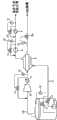
Fig. 1 is the scheme drawing of the fuel gas supply system of steamer according to an embodiment of the invention.As illustrated in fig. 1, the fuel gas supply system of steamer is given gas supply in the spraying high-pressure gas engine of steamer.
The fuel gas supply system of Fig. 1 comprises: gas supply pipeline L1, and it is used for the LNG that the LNG storage tank 1 from steamer extracts is supplied to the spraying high-pressure gas engine of described steamer; And H Exch 3, it is installed in the middle of the gas supply pipeline L1 so that at LNG and from exchanged heat between the boil-off gas of LNG storage tank 1 extraction.
Described steamer can be the LNG carrier.The LNG carrier has the LNG holding vessel that is used to store LNG.In this case, LNG storage tank 1 is the LNG holding vessel.
In addition, described steamer can be the steamer that can use LNG to act as a fuel and advance, for example bulk carrier, box ship, crude oil tanker and chemical carrying ship.This type of steamer has the LNG fuel reservoir that is used to store the LNG that acts as a fuel.In this case, LNG storage tank 1 is for being used to store the LNG fuel reservoir of the LNG that acts as a fuel.
Gas supply pipeline L1 in H Exch 3 upstreams has first pump 2, is used to compress that LNG requires with the pressure that satisfies described spraying high-pressure gas engine and to described spraying high-pressure gas engine supply LNG.According to this embodiment, first pump 2 is illustrated as is installed in the LNG storage tank 1, but can be installed among the gas supply pipeline L1 of LNG storage tank 1 external heat exchanger 3 upstreams.First pump 2 also can comprise a pump or two pumps.
Boil-off gas liquefaction pipeline L2 from the top part of LNG storage tank 1, pass H Exch 3, be connected to a side of LNG storage tank 1.The top part of boil-off gas from LNG storage tank 1 extracted, pass H Exch 3, and turn back to a side of LNG storage tank 1.
In H Exch 3, LNG and boil-off gas exchanged heat is so that the temperature build-up of LNG, and then to described spraying high-pressure gas engine supply LNG, and boil-off gas interchange of heat liquefies and then turn back to LNG storage tank 1 by carrying out with LNG.If the boil-off gas in the top part of LNG storage tank 1 liquefaction also turns back to the bottom part of LNG storage tank 1, can prevent that so the pressure in the LNG storage tank 1 from increasing too much owing to gathering of boil-off gas in the LNG storage tank 1.
In one embodiment, second pump 4 is installed among the gas supply pipeline L1 in H Exch 3 downstreams, so that compression with the LNG of boil-off gas exchanged heat satisfying the pressure requirement of described spraying high-pressure gas engine, and then compressed LNG is supplied to described spraying high-pressure gas engine.
Temperature booster 5 be installed among the gas supply pipeline L1 in second pump, 4 downstreams in case in H Exch 3 LNG of exchanged heat heat, and then will be supplied to described spraying high-pressure gas engine through interchange of heat LNG.
In one embodiment, boil-off gas compressor 6 and cooling vessel 7 are installed among the boil-off gas liquefaction pipeline L2 of H Exch 3 upstreams, so that compressed and cool off the boil-off gas that extracts from LNG storage tank 1 before carrying out interchange of heat between boil-off gas and the LNG.
Under the situation of the MEGI engine that described spraying high-pressure gas engine is made and sold by Man Enbiwei diesel engine company for (for example), the pressure of the combustion gas that the MEGI engine is required can cling to 300 crust (gauge pressures from 200, gauge pressure), preferably 250 cling to (gauge pressure).In first pump 2, LNG is compressed to 27 and clings to (gauge pressure), and LNG temperature when passing H Exch 3 is elevated to-100 degrees centigrade approximately from about-163 degrees centigrade, and the LNG that will be in liquid state is supplied to second pump 4 and in second pump 4 it is compressed to about 250 crust (gauge pressure) (because it is in supercriticality, do not divide so between liquid state and gaseous state, have), then heating in temperature booster 5, and then be supplied to described spraying high-pressure gas engine.In this case, be high owing to be supplied to the pressure of the LNG of H Exch 3, although therefore the temperature of LNG raises because of passing H Exch, it does not aerify.
On the other hand, be under the situation of (for example) gas-turbine engine at described spraying high-pressure gas engine, the pressure of the combustion gas that the gas-turbine engine is required can cling to 40 from 20 and cling to (gauge pressure), preferably 30 crust (gauge pressure).In first pump 2, LNG is compressed to 30 and clings to (gauge pressure), and the part of LNG aerifies when passing H Exch 3, it is supplied to temperature booster 5 and heating in temperature booster 5, and then be supplied to described spraying high-pressure gas engine.In this case, second pump 4 and nonessential.
Flow rate controllable type pressure-gradient control valve 11 is installed among the gas supply pipeline L1 at front and rear place of first pump 2, among the gas supply pipeline L1 at the front and rear place of second pump 4, and among the boil-off gas at the front and rear place of boil-off gas compressor 6 and the cooling vessel 7 liquefaction pipeline L2, so that the pressure of the fluid of described pipeline is passed in control.
Flow rate controllable typetemperature control valve 12 also is installed in thegas supply pipeline 11 at front and rear place of temperature booster 5 so that the temperature of the fluid of pipeline is passed in control.
Flow rate controllable type pressure-gradient control valve 11 andtemperature control valve 12 control flow rates, the pressure or the temperature of the fluid of himself passed in control thus.
And inflatable pressure-gradient control valve 12a is installed in the boil-off gas liquefaction pipeline L2 centre in H Exch 3 downstreams so that the pressure of the fluid of pipeline L2 is passed in control.
The boil-off gas thatpressure sensor 13 is connected the front end place of pressure-gradient control valve 12a and pressure-gradient control valve 12a liquefies between the pipeline L2, and described pressure-gradient control valve 12a is installed among the boil-off gas liquefaction pipeline L2 in H Exch 3 downstreams.
The pressure-gradient control valve 12a that is installed among the boil-off gas liquefaction pipeline L2 in H Exch 3 downstreams makes the fluid expansion that passes, so that the pressure that the pressure that causes corresponding to the head that adds by the pressure with LNG storage tank 1 owing to the LNG in the LNG storage tank 1 obtains, control presssure thus, and make the drop in temperature of LNG by described expansion.
In one embodiment, as illustrated in fig. 2, evaporation liquefaction pipeline L2 can be configured, and makes its top part from LNG storage tank 1 pass H Exch 3, and is connected between gas supply pipeline the L1 middle H Exch 3 and temperature booster 5.According to this configuration, boil-off gas liquefies by carry out interchange of heat with LNG in H Exch 3, in liquid lower compression, aerifies, and then is used as the combustion gas of described spraying high-pressure gas engine.In this case, be installed in the pressure of the fluid that the pressure-gradient control valve 12a control among the boil-off gas liquefaction pipeline L2 in H Exch 3 downstreams passes, with pressure corresponding to the LNG among the gas supply pipeline L1.
According to the foregoing description, the H Exch 3 that is used in exchanged heat between LNG and the boil-off gas that extracts from LNG storage tank 1 is installed in the middle of the gas supply pipeline L1.Yet, substitute H Exch 3, can install and be used for after-condenser that LNG and boil-off gas are directly mixed.According to embodiment illustrated in fig. 3, the after-condenser 103 that substitutes H Exch is installed among the gas supply pipeline L1.Be used for passing the after-condenser 103 that is installed in gas supply pipeline L1 centre from the boil-off gas liquefaction pipeline L2 that the top part of LNG storage tank 1 extracts boil-off gas and makes the boil-off gas that is extracted turn back to a side of LNG storage tank 1.After-condenser 103 mixes/liquefies the LNG that produces condensation by the LNG that will extract from the bottom part of LNG storage tank 1 with boil-off gas from the top part extraction of LNG storage tank 1.The LNG of condensation is supplied to the spraying high-pressure gas engine by gas supply pipeline L1 in after-condenser 103, or turns back to LNG storage tank 1 by boil-off gas liquefaction pipeline L2.
And according to the fuel gas supply system of steamer of the present invention, the boil-off gas that produces in the LNG storage tank is under high pressure in the gaseous state lower compression, and therefore not as the combustion gas of spraying high-pressure gas engine.
In addition, the LNG storage tank that is used for the fuel gas supply system of steamer according to an embodiment of the invention can be through design, making it have sufficient intensity increases with the pressure that causes owing to boil-off gas of tolerance, so that the pressure that allows the term of voyage at steamer to cause owing to the boil-off gas that produces in the LNG storage tank increases.
In addition, the fuel gas supply system of steamer can comprise the boil-off gas liquefaction device again that comprises ice chest and refrigerating system according to an embodiment of the invention.H Exch is installed in the middle of the gas supply pipeline, be used for compressing the LNG of LNG storage tank and will being supplied to the spraying high-pressure gas engine as the compressed LNG of combustion gas, and combustion gas that produces in the LNG storage tank and the LNG exchanged heat in the middle of the boil-off gas supply line, and liquefaction thus.Therefore, the boil-off gas of installing in addition again liquefaction device can be configured to have low capacity.
Although shown with reference to specific embodiment in this article and described the present invention, but should understand, therefore the those skilled in the art can carry out various modifications, variation and correction, and herein description and accompanying drawing should be explained with illustration purpose but not limit the scope of the invention and spirit.
Claims (20)
1. the fuel gas supply system of a steamer is used for gas supply is given the spraying high-pressure gas engine of described steamer, it is characterized in that described fuel gas supply system comprises:
The LNG storage tank;
The gas supply pipeline is connected to the described spraying high-pressure gas engine of described steamer from described LNG storage tank;
Be used to compress the compression element of described LNG, be installed in the described gas supply pipeline between described LNG storage tank and the described spraying high-pressure gas engine; And
Be used to make the aerification member of described LNG aerification, be installed in the downstream of the described compression element in the described gas supply pipeline, so that compressed described LNG aerifies.
2. the fuel gas supply system of steamer according to claim 1, it is characterized in that described compression element is configured to extract LNG from described LNG storage tank, the described LNG that compression has under high pressure extracted, and to the compressed described LNG of described spraying high-pressure gas engine supply.
3. the fuel gas supply system of steamer according to claim 1 is characterized in that described compression element comprises a pump.
4. the fuel gas supply system of steamer according to claim 3 is characterized in that described compression element further comprises another pump.
5. the fuel gas supply system of steamer according to claim 3 is characterized in that, further comprises:
H Exch is installed in the downstream of this pump in the described gas supply pipeline; And
Boil-off gas liquefaction pipeline passes the side that described H Exch is connected to described LNG storage tank from the top part of described LNG storage tank, and described boil-off gas liquefaction pipeline is configured so that the boil-off gas liquefaction that produces in the described LNG storage tank.
6. the fuel gas supply system of steamer according to claim 4 further comprises:
H Exch is installed between this pump and this another pump in the described gas supply pipeline; And
Boil-off gas liquefaction pipeline passes described H Exch from the top part of described LNG storage tank, and is connected between described H Exch and the described aerification member.
7. the fuel gas supply system of steamer according to claim 3 is characterized in that, further comprises:
After-condenser is installed in the downstream of this pump in the described gas supply pipeline; And
Boil-off gas liquefaction pipeline from the top part of described LNG storage tank, passes described after-condenser, and is connected to described LNG storage tank.
8. the fuel gas supply system of steamer according to claim 1 is characterized in that described aerification member comprises temperature booster.
9. the fuel gas supply system of steamer according to claim 1 is characterized in that LNG is extracted out from described LNG storage tank, and then be compressed to about 20 cling to 300 the crust gauge pressures.
10. the fuel gas supply system of steamer according to claim 1, it is characterized in that described LNG storage tank increases with the pressure that causes owing to described boil-off gas of tolerance through design, the pressure that causes increases so that allow the described boil-off gas that term of voyage at described steamer produces in owing to described LNG storage tank.
11. the fuel gas supply system of steamer according to claim 1 it is characterized in that described steamer is the LNG carrier, and described LNG storage tank is the LNG holding vessel.
12. the fuel gas supply system of steamer according to claim 1, it is characterized in that described steamer is for example steamer of bulk carrier, box ship, crude oil tanker and chemical carrying ship, and described LNG storage tank is the LNG fuel reservoir that is used to store the LNG that acts as a fuel.
13. the gas supply method of a LNG carrier is used for the spraying high-pressure gas engine of gas supply to steamer be is characterized in that described method comprises:
Extract LNG from the LNG storage tank of described steamer;
The described LNG that compression has extracted is to satisfy the pressure requirement of described spraying high-pressure gas engine;
Compressed described LNG is aerified; And
Described LNG through aerifying is supplied to described spraying high-pressure gas engine.
14. the gas supply method of steamer according to claim 13 is characterized in that, further comprises:
Extract boil-off gas from described LNG storage tank; And
Before described LNG is supplied to described spraying high-pressure gas engine, exchanged heat between described LNG and described boil-off gas.
15. the gas supply method of steamer according to claim 14 is characterized in that, further comprises:
Make described boil-off gas liquefaction; And
Make described boil-off gas turn back to described LNG storage tank through liquefaction.
16. the gas supply method of steamer according to claim 14 is characterized in that, further comprises:
Before described LNG is supplied to described spraying high-pressure gas engine, make the temperature build-up of described LNG via the described interchange of heat between described LNG and the described boil-off gas;
Make described boil-off gas liquefaction; And
The described boil-off gas that has liquefied is supplied to described spraying high-pressure gas engine.
17. the gas supply method of steamer according to claim 13 is characterized in that, further comprises:
Described LNG is mixed with the described boil-off gas that extracts from described LNG storage tank; And
The described compound of described LNG and described boil-off gas is supplied to described spraying high-pressure gas engine.
18. the gas supply method of steamer according to claim 13 is characterized in that described LNG aerifies by heating.
19. the gas supply method of steamer according to claim 13 is characterized in that, further comprises:
The described boil-off gas that permission produces in owing to described LNG storage tank at the term of voyage of described steamer and the pressure that causes increases.
20. the gas supply method of steamer according to claim 13, the LNG pressure that it is characterized in that described spraying high-pressure gas engine are to cling to about 300 crust gauge pressures from about 20.
Applications Claiming Priority (9)
| Application Number | Priority Date | Filing Date | Title |
|---|---|---|---|
| KR1020070072242AKR101076266B1 (en) | 2007-07-19 | 2007-07-19 | System for supplying fuel gas in lng carrier |
| KR10-2007-0072242 | 2007-07-19 | ||
| KR10-2007-0121558 | 2007-11-27 | ||
| KR1020070121558AKR100835090B1 (en) | 2007-05-08 | 2007-11-27 | Fuel gas supply system and method of LG carrier |
| KR1020070123679AKR100850833B1 (en) | 2007-05-08 | 2007-11-30 | Fuel gas supply system and method of LG carrier |
| KR10-2007-0123679 | 2007-11-30 | ||
| KR1020080020356AKR100978063B1 (en) | 2007-05-08 | 2008-03-05 | Fuel gas supply system and method of ship |
| KR10-2008-0020356 | 2008-03-05 | ||
| PCT/KR2008/003497WO2009011497A2 (en) | 2007-07-19 | 2008-06-19 | Fuel gas supply system and method of ship |
Related Child Applications (1)
| Application Number | Title | Priority Date | Filing Date |
|---|---|---|---|
| CN2012103798423ADivisionCN103010447A (en) | 2007-07-19 | 2008-06-19 | Fuel gas supply system and method of ship |
Publications (2)
| Publication Number | Publication Date |
|---|---|
| CN101754897Atrue CN101754897A (en) | 2010-06-23 |
| CN101754897B CN101754897B (en) | 2013-08-28 |
Family
ID=40260201
Family Applications (2)
| Application Number | Title | Priority Date | Filing Date |
|---|---|---|---|
| CN2008800250353AActiveCN101754897B (en) | 2007-07-19 | 2008-06-19 | Gas supply system and method for ships |
| CN2012103798423APendingCN103010447A (en) | 2007-07-19 | 2008-06-19 | Fuel gas supply system and method of ship |
Family Applications After (1)
| Application Number | Title | Priority Date | Filing Date |
|---|---|---|---|
| CN2012103798423APendingCN103010447A (en) | 2007-07-19 | 2008-06-19 | Fuel gas supply system and method of ship |
Country Status (8)
| Country | Link |
|---|---|
| EP (7) | EP2840295A3 (en) |
| KR (1) | KR101076266B1 (en) |
| CN (2) | CN101754897B (en) |
| DK (2) | DK2447592T3 (en) |
| ES (2) | ES2582606T3 (en) |
| HR (2) | HRP20160599T1 (en) |
| PL (2) | PL2121425T3 (en) |
| WO (1) | WO2009011497A2 (en) |
Cited By (15)
| Publication number | Priority date | Publication date | Assignee | Title |
|---|---|---|---|---|
| CN102563343A (en)* | 2010-11-29 | 2012-07-11 | 通用汽车环球科技运作有限责任公司 | Compressed gas tank system with fast fueling ability at any vessel pressure |
| CN103189273A (en)* | 2010-08-25 | 2013-07-03 | 瓦特西拉石油和天然气系统有限公司 | A method and arrangement for providing LNG fuel for ships |
| CN103547787A (en)* | 2011-03-22 | 2014-01-29 | 大宇造船海洋株式会社 | System for fueling a high pressure natural gas injected engine having excess boil-off gas consumption components |
| CN103547788A (en)* | 2011-03-22 | 2014-01-29 | 大宇造船海洋株式会社 | Non-explosive mixed refrigerants for reliquefaction units in systems feeding fuel to high-pressure natural gas injection engines |
| CN103619705A (en)* | 2011-05-31 | 2014-03-05 | 大宇造船海洋株式会社 | Cold heat recovery apparatus using an lng fuel, and liquefied gas carrier including same |
| WO2015078106A1 (en)* | 2013-11-29 | 2015-06-04 | 中国海洋石油总公司 | Liquid anti-rolling, positioned filling and circulating apparatus for liquefied natural gas storage tank |
| CN104781532A (en)* | 2012-10-24 | 2015-07-15 | 大宇造船海洋株式会社 | System for processing liquefied gas on vessel |
| CN104903186A (en)* | 2014-01-07 | 2015-09-09 | 大宇造船海洋株式会社 | Apparatus and method for supplying fuel gas in ship |
| CN105089856A (en)* | 2015-07-15 | 2015-11-25 | 江苏科技大学 | Self-sufficient type internal combustion engine gas fuel supply system and gas packet pressure control method |
| CN106029491A (en)* | 2014-02-28 | 2016-10-12 | 大宇造船海洋株式会社 | Evaporative Gas Treatment System |
| CN107107996A (en)* | 2014-12-26 | 2017-08-29 | 川崎重工业株式会社 | Liquefied gas carry vessel |
| CN107435600A (en)* | 2016-05-26 | 2017-12-05 | 曼柴油机欧洲股份公司曼柴油机德国分公司 | The fuel feed system of large-sized two-stroke compression ignition type high-pressure gas injection internal combustion engine |
| CN110402329A (en)* | 2017-03-16 | 2019-11-01 | 沃尔沃卡车集团 | Fuel system for internal combustion engine |
| CN110486204A (en)* | 2019-07-12 | 2019-11-22 | 西安交通大学 | A kind of methanol engine air inlet pipe multi-point sequent high-pressure injection system |
| CN111315966A (en)* | 2017-11-10 | 2020-06-19 | 247能源有限公司 | compact power generation equipment |
Families Citing this family (19)
| Publication number | Priority date | Publication date | Assignee | Title |
|---|---|---|---|---|
| MX2010010706A (en) | 2008-04-11 | 2010-11-01 | Fluor Tech Corp | Methods and configuration of boil-off gas handling in lng regasification terminals. |
| KR101149507B1 (en)* | 2009-07-31 | 2012-05-25 | 삼성중공업 주식회사 | Apparatus for treating boil-off gas |
| KR100961869B1 (en)* | 2009-10-16 | 2010-06-09 | 대우조선해양 주식회사 | Ship for running alternatively a liquified gas fuelled main drive engine or a liquified gas fuelled generator engine |
| KR100961867B1 (en) | 2009-10-16 | 2010-06-09 | 대우조선해양 주식회사 | Floating structure with a fuel gas tank |
| CN102155614B (en)* | 2011-01-21 | 2013-05-01 | 中国石油天然气股份有限公司 | Recovery method and system for natural gas of marginal offshore oil field |
| KR101106089B1 (en)* | 2011-03-11 | 2012-01-18 | 대우조선해양 주식회사 | Fuel supply method for high pressure natural gas injection engine |
| KR101368796B1 (en)* | 2012-03-16 | 2014-03-03 | 삼성중공업 주식회사 | Liquefied fuel gas propulsion ship |
| KR20160015699A (en)* | 2014-07-31 | 2016-02-15 | 대우조선해양 주식회사 | Fuel Supply System And Method |
| CN104564432A (en)* | 2014-12-26 | 2015-04-29 | 无锡博利达换热器有限公司 | Combined type natural gas cooler |
| CN104879243B (en)* | 2014-12-26 | 2017-10-10 | 无锡久盛换热器有限公司 | The natural Gas Cooler of explosion-proof type |
| JP6513815B2 (en) | 2015-01-30 | 2019-05-15 | デウ シップビルディング アンド マリン エンジニアリング カンパニー リミテッド | Fuel supply system for a marine engine and fuel supply method |
| JP6541059B2 (en)* | 2015-04-10 | 2019-07-10 | 三井E&S造船株式会社 | Fuel gas supply system for liquefied gas carrier |
| KR101613236B1 (en)* | 2015-07-08 | 2016-04-18 | 대우조선해양 주식회사 | Vessel Including Engines and Method of Reliquefying Boil-Off Gas for The Same |
| JP6592354B2 (en)* | 2015-11-06 | 2019-10-16 | 川崎重工業株式会社 | Ship |
| KR101751854B1 (en)* | 2015-11-12 | 2017-06-28 | 대우조선해양 주식회사 | Vessel |
| DE102017118951B4 (en)* | 2017-08-18 | 2019-11-14 | Arianegroup Gmbh | Cooling of an evaporation of liquefied petroleum gas to drive machines, plants or vehicles |
| JP7398264B2 (en)* | 2019-12-19 | 2023-12-14 | 三菱造船株式会社 | ship |
| DE102020113548A1 (en)* | 2020-05-19 | 2021-11-25 | Tge Marine Gas Engineering Gmbh | Provision of fuel gas for a fuel gas machine |
| CN112344207B (en)* | 2020-10-12 | 2021-12-31 | 华中科技大学 | Liquid hydrogen and high-pressure gas hydrogen combined hydrogenation system based on injection mixed pressure |
Family Cites Families (12)
| Publication number | Priority date | Publication date | Assignee | Title |
|---|---|---|---|---|
| GB1472533A (en)* | 1973-06-27 | 1977-05-04 | Petrocarbon Dev Ltd | Reliquefaction of boil-off gas from a ships cargo of liquefied natural gas |
| NO960836A (en)* | 1996-02-29 | 1997-05-05 | Kvaerner Maritime As | Method of utilizing decoction from liquefied gas and plants for carrying out the method |
| JP3790393B2 (en)* | 1999-11-05 | 2006-06-28 | 大阪瓦斯株式会社 | Cargo tank pressure control device and pressure control method for LNG carrier |
| KR100441857B1 (en)* | 2002-03-14 | 2004-07-27 | 대우조선해양 주식회사 | Boil off gas rel iquefaction method and system assembly of Liquefied natural gas carrier |
| FR2851301A1 (en)* | 2003-02-19 | 2004-08-20 | Alstom | Gaseous fuel supplying equipment for ship, has accumulator connected to supply collector of energy production assembly by valve and having gas under pressure greater than supply pressure |
| KR100547696B1 (en)* | 2004-06-22 | 2006-01-31 | 대우조선해양 주식회사 | Evaporative gas supply structure of main engine of LNG carrier |
| FR2879261B1 (en)* | 2004-12-10 | 2007-04-13 | Alstom Sa | INSTALLATION FOR THE DELIVERY OF GASEOUS FUEL TO AN ENERGY PRODUCTION ASSEMBLY OF A LIQUEFIED GAS TRANSPORT VESSEL |
| KR100655863B1 (en)* | 2005-05-25 | 2006-12-13 | 삼성중공업 주식회사 | Fuel supply device of electric propulsion LNG carrier |
| JP2006348752A (en)* | 2005-06-13 | 2006-12-28 | Kawasaki Shipbuilding Corp | Evaporated-gas supply system for liquefied natural gas-carrying vessel |
| KR100726290B1 (en) | 2005-12-29 | 2007-06-11 | 삼성중공업 주식회사 | Evaporative Gas Recycling Method and Device |
| US8820096B2 (en)* | 2007-02-12 | 2014-09-02 | Daewoo Shipbuilding & Marine Engineering Co., Ltd. | LNG tank and operation of the same |
| KR100835090B1 (en)* | 2007-05-08 | 2008-06-03 | 대우조선해양 주식회사 | Fuel gas supply system and method of LG carrier |
- 2007
- 2007-07-19KRKR1020070072242Apatent/KR101076266B1/enactiveActive
- 2008
- 2008-06-19EPEP20140191351patent/EP2840295A3/ennot_activeWithdrawn
- 2008-06-19ESES12000493.2Tpatent/ES2582606T3/enactiveActive
- 2008-06-19DKDK12000492.4Tpatent/DK2447592T3/enactive
- 2008-06-19EPEP08766457.9Apatent/EP2121425B1/enactiveActive
- 2008-06-19EPEP11009863.9Apatent/EP2444712B1/enactiveActive
- 2008-06-19ESES08766457.9Tpatent/ES2581742T3/enactiveActive
- 2008-06-19EPEP20140191341patent/EP2848856A3/ennot_activeWithdrawn
- 2008-06-19PLPL08766457.9Tpatent/PL2121425T3/enunknown
- 2008-06-19HRHRP20160599TTpatent/HRP20160599T1/enunknown
- 2008-06-19EPEP16000712.6Apatent/EP3056793A1/ennot_activeWithdrawn
- 2008-06-19PLPL12000493.2Tpatent/PL2447593T3/enunknown
- 2008-06-19DKDK11009863.9Tpatent/DK2444712T3/enactive
- 2008-06-19CNCN2008800250353Apatent/CN101754897B/enactiveActive
- 2008-06-19EPEP12000493.2Apatent/EP2447593B1/enactiveActive
- 2008-06-19CNCN2012103798423Apatent/CN103010447A/enactivePending
- 2008-06-19WOPCT/KR2008/003497patent/WO2009011497A2/ennot_activeCeased
- 2008-06-19EPEP12000492.4Apatent/EP2447592B1/enactiveActive
- 2016
- 2016-06-02HRHRP20160595TTpatent/HRP20160595T1/enunknown
Cited By (25)
| Publication number | Priority date | Publication date | Assignee | Title |
|---|---|---|---|---|
| CN103189273A (en)* | 2010-08-25 | 2013-07-03 | 瓦特西拉石油和天然气系统有限公司 | A method and arrangement for providing LNG fuel for ships |
| CN103189273B (en)* | 2010-08-25 | 2017-02-08 | 瓦特西拉石油和天然气系统有限公司 | Method and apparatus for fueling ships with liquefied natural gas |
| CN102563343B (en)* | 2010-11-29 | 2015-10-14 | 通用汽车环球科技运作有限责任公司 | The compressed gas tank system of quick fueling ability is all had under any container pressure |
| CN102563343A (en)* | 2010-11-29 | 2012-07-11 | 通用汽车环球科技运作有限责任公司 | Compressed gas tank system with fast fueling ability at any vessel pressure |
| CN103547788A (en)* | 2011-03-22 | 2014-01-29 | 大宇造船海洋株式会社 | Non-explosive mixed refrigerants for reliquefaction units in systems feeding fuel to high-pressure natural gas injection engines |
| CN103547787A (en)* | 2011-03-22 | 2014-01-29 | 大宇造船海洋株式会社 | System for fueling a high pressure natural gas injected engine having excess boil-off gas consumption components |
| CN103619705A (en)* | 2011-05-31 | 2014-03-05 | 大宇造船海洋株式会社 | Cold heat recovery apparatus using an lng fuel, and liquefied gas carrier including same |
| CN104781532A (en)* | 2012-10-24 | 2015-07-15 | 大宇造船海洋株式会社 | System for processing liquefied gas on vessel |
| CN104781532B (en)* | 2012-10-24 | 2018-06-05 | 大宇造船海洋株式会社 | Liquefaction gas processing system and liquefied gas processing method on ship |
| WO2015078106A1 (en)* | 2013-11-29 | 2015-06-04 | 中国海洋石油总公司 | Liquid anti-rolling, positioned filling and circulating apparatus for liquefied natural gas storage tank |
| CN104903186A (en)* | 2014-01-07 | 2015-09-09 | 大宇造船海洋株式会社 | Apparatus and method for supplying fuel gas in ship |
| CN104903186B (en)* | 2014-01-07 | 2017-11-14 | 大宇造船海洋株式会社 | The fuel gas supply system and method for ship |
| US9738368B2 (en) | 2014-01-07 | 2017-08-22 | Daewoo Shipbuilding & Marine Engineering Co., Ltd. | Fuel gas supply system and method of ship |
| CN106029491A (en)* | 2014-02-28 | 2016-10-12 | 大宇造船海洋株式会社 | Evaporative Gas Treatment System |
| CN107107996B (en)* | 2014-12-26 | 2019-10-25 | 川崎重工业株式会社 | LPG carrier |
| CN107107996A (en)* | 2014-12-26 | 2017-08-29 | 川崎重工业株式会社 | Liquefied gas carry vessel |
| CN105089856B (en)* | 2015-07-15 | 2017-06-20 | 江苏科技大学 | Self contained internal-combustion engine gas fuel feed system and gas bag compress control method |
| CN105089856A (en)* | 2015-07-15 | 2015-11-25 | 江苏科技大学 | Self-sufficient type internal combustion engine gas fuel supply system and gas packet pressure control method |
| CN107435600A (en)* | 2016-05-26 | 2017-12-05 | 曼柴油机欧洲股份公司曼柴油机德国分公司 | The fuel feed system of large-sized two-stroke compression ignition type high-pressure gas injection internal combustion engine |
| CN107435600B (en)* | 2016-05-26 | 2019-12-31 | 曼能解决方案(曼能解决方案德国股份公司)分公司 | Fuel supply system of large two-stroke compression ignition type high-pressure gas injection internal combustion engine |
| CN110402329A (en)* | 2017-03-16 | 2019-11-01 | 沃尔沃卡车集团 | Fuel system for internal combustion engine |
| CN110402329B (en)* | 2017-03-16 | 2021-06-29 | 沃尔沃卡车集团 | Fuel systems for internal combustion engines |
| CN111315966A (en)* | 2017-11-10 | 2020-06-19 | 247能源有限公司 | compact power generation equipment |
| US11402068B2 (en) | 2017-11-10 | 2022-08-02 | 247 Energy Bvba | Compact power plant |
| CN110486204A (en)* | 2019-07-12 | 2019-11-22 | 西安交通大学 | A kind of methanol engine air inlet pipe multi-point sequent high-pressure injection system |
Also Published As
| Publication number | Publication date |
|---|---|
| WO2009011497A3 (en) | 2009-03-19 |
| EP2447592A1 (en) | 2012-05-02 |
| CN103010447A (en) | 2013-04-03 |
| DK2447592T3 (en) | 2019-08-26 |
| EP2447593A1 (en) | 2012-05-02 |
| EP2121425A4 (en) | 2011-08-10 |
| EP2848856A2 (en) | 2015-03-18 |
| EP3056793A1 (en) | 2016-08-17 |
| EP2447592B1 (en) | 2019-08-07 |
| ES2582606T3 (en) | 2016-09-14 |
| EP2840295A3 (en) | 2015-04-29 |
| EP2121425A2 (en) | 2009-11-25 |
| PL2121425T3 (en) | 2016-10-31 |
| EP2444712B1 (en) | 2019-08-07 |
| EP2121425B1 (en) | 2016-04-13 |
| PL2447593T3 (en) | 2016-10-31 |
| HRP20160595T1 (en) | 2016-07-01 |
| EP2848856A3 (en) | 2015-04-29 |
| DK2444712T3 (en) | 2019-08-26 |
| KR101076266B1 (en) | 2011-10-26 |
| CN101754897B (en) | 2013-08-28 |
| KR20090008900A (en) | 2009-01-22 |
| EP2447593B1 (en) | 2016-04-20 |
| HRP20160599T1 (en) | 2016-07-01 |
| EP2840295A2 (en) | 2015-02-25 |
| ES2581742T3 (en) | 2016-09-07 |
| EP2444712A1 (en) | 2012-04-25 |
| WO2009011497A2 (en) | 2009-01-22 |
Similar Documents
| Publication | Publication Date | Title |
|---|---|---|
| CN101754897A (en) | Fuel gas supply system and method for ship | |
| EP1990272B1 (en) | Fuel gas supply system and method of an LNG carrier | |
| KR102127551B1 (en) | A Vessel having a regasification System of gas | |
| US9206776B2 (en) | Fuel feeding system and method of operating a fuel feeding system | |
| KR101883858B1 (en) | liquefaction system of boil-off gas and ship having the same | |
| KR101670872B1 (en) | Fuel Gas Supply System And Method For Ship Engine | |
| KR102192107B1 (en) | treatment system for gas and vessel having the same | |
| KR101681715B1 (en) | Fuel Gas Supply System And Method For Ship Engine | |
| KR20230047304A (en) | Gas treatment system and ship having the same | |
| CN115697836A (en) | Fuel supply system and method for liquefied gas carrier | |
| KR102337788B1 (en) | treatment system for gas and vessel having the same | |
| KR102553159B1 (en) | Gas treatment system and ship having the same | |
| KR102638284B1 (en) | Fuel Gas Supply System And Method For Ship | |
| KR20230121639A (en) | Fuel supply system of Liquefied gas |
Legal Events
| Date | Code | Title | Description |
|---|---|---|---|
| C06 | Publication | ||
| PB01 | Publication | ||
| C10 | Entry into substantive examination | ||
| SE01 | Entry into force of request for substantive examination | ||
| C14 | Grant of patent or utility model | ||
| GR01 | Patent grant | ||
| IP01 | Partial invalidation of patent right | ||
| IP01 | Partial invalidation of patent right | Commission number:4W104674 Conclusion of examination:Claim No. 200880025035.3 of the invention No. 12-17 is invalid, and the patent right is maintained on the basis of claim 1-11. Decision date of declaring invalidation:20170126 Decision number of declaring invalidation:31198 Denomination of invention:Fuel gas supply system and method of ship Granted publication date:20130828 Patentee:DAEWOO SHIPBUILDING & MARINE ENGINEERING Co.,Ltd. | |
| CP03 | Change of name, title or address | ||
| CP03 | Change of name, title or address | Address after:3370 Juti Road, Juji City, Gyeongsangnam do, South Korea Patentee after:Hanhua Ocean Co.,Ltd. Country or region after:China Address before:Seoul special city Patentee before:DAEWOO SHIPBUILDING & MARINE ENGINEERING Co.,Ltd. Country or region before:Republic of Korea |