CN101744648A - Endoscopic surgical clip applier with connecting plate - Google Patents
Endoscopic surgical clip applier with connecting plateDownload PDFInfo
- Publication number
- CN101744648A CN101744648ACN200910171615ACN200910171615ACN101744648ACN 101744648 ACN101744648 ACN 101744648ACN 200910171615 ACN200910171615 ACN 200910171615ACN 200910171615 ACN200910171615 ACN 200910171615ACN 101744648 ACN101744648 ACN 101744648A
- Authority
- CN
- China
- Prior art keywords
- clip
- plate
- push rod
- distal
- wedge plate
- Prior art date
- Legal status (The legal status is an assumption and is not a legal conclusion. Google has not performed a legal analysis and makes no representation as to the accuracy of the status listed.)
- Granted
Links
Images


Classifications
- A—HUMAN NECESSITIES
- A61—MEDICAL OR VETERINARY SCIENCE; HYGIENE
- A61B—DIAGNOSIS; SURGERY; IDENTIFICATION
- A61B17/00—Surgical instruments, devices or methods
- A61B17/10—Surgical instruments, devices or methods for applying or removing wound clamps, e.g. containing only one clamp or staple; Wound clamp magazines
- A61B17/105—Wound clamp magazines
- A—HUMAN NECESSITIES
- A61—MEDICAL OR VETERINARY SCIENCE; HYGIENE
- A61B—DIAGNOSIS; SURGERY; IDENTIFICATION
- A61B17/00—Surgical instruments, devices or methods
- A61B17/12—Surgical instruments, devices or methods for ligaturing or otherwise compressing tubular parts of the body, e.g. blood vessels or umbilical cord
- A61B17/128—Surgical instruments, devices or methods for ligaturing or otherwise compressing tubular parts of the body, e.g. blood vessels or umbilical cord for applying or removing clamps or clips
- A61B17/1285—Surgical instruments, devices or methods for ligaturing or otherwise compressing tubular parts of the body, e.g. blood vessels or umbilical cord for applying or removing clamps or clips for minimally invasive surgery
- A—HUMAN NECESSITIES
- A61—MEDICAL OR VETERINARY SCIENCE; HYGIENE
- A61B—DIAGNOSIS; SURGERY; IDENTIFICATION
- A61B17/00—Surgical instruments, devices or methods
- A61B17/00234—Surgical instruments, devices or methods for minimally invasive surgery
- A—HUMAN NECESSITIES
- A61—MEDICAL OR VETERINARY SCIENCE; HYGIENE
- A61B—DIAGNOSIS; SURGERY; IDENTIFICATION
- A61B17/00—Surgical instruments, devices or methods
- A61B17/068—Surgical staplers, e.g. containing multiple staples or clamps
- A61B17/072—Surgical staplers, e.g. containing multiple staples or clamps for applying a row of staples in a single action, e.g. the staples being applied simultaneously
- A—HUMAN NECESSITIES
- A61—MEDICAL OR VETERINARY SCIENCE; HYGIENE
- A61B—DIAGNOSIS; SURGERY; IDENTIFICATION
- A61B17/00—Surgical instruments, devices or methods
- A61B17/08—Wound clamps or clips, i.e. not or only partly penetrating the tissue ; Devices for bringing together the edges of a wound
- A61B17/083—Clips, e.g. resilient
- A—HUMAN NECESSITIES
- A61—MEDICAL OR VETERINARY SCIENCE; HYGIENE
- A61B—DIAGNOSIS; SURGERY; IDENTIFICATION
- A61B17/00—Surgical instruments, devices or methods
- A61B17/10—Surgical instruments, devices or methods for applying or removing wound clamps, e.g. containing only one clamp or staple; Wound clamp magazines
- A—HUMAN NECESSITIES
- A61—MEDICAL OR VETERINARY SCIENCE; HYGIENE
- A61B—DIAGNOSIS; SURGERY; IDENTIFICATION
- A61B17/00—Surgical instruments, devices or methods
- A61B17/28—Surgical forceps
- A61B17/29—Forceps for use in minimally invasive surgery
- A—HUMAN NECESSITIES
- A61—MEDICAL OR VETERINARY SCIENCE; HYGIENE
- A61B—DIAGNOSIS; SURGERY; IDENTIFICATION
- A61B90/00—Instruments, implements or accessories specially adapted for surgery or diagnosis and not covered by any of the groups A61B1/00 - A61B50/00, e.g. for luxation treatment or for protecting wound edges
- A61B90/08—Accessories or related features not otherwise provided for
- A—HUMAN NECESSITIES
- A61—MEDICAL OR VETERINARY SCIENCE; HYGIENE
- A61B—DIAGNOSIS; SURGERY; IDENTIFICATION
- A61B1/00—Instruments for performing medical examinations of the interior of cavities or tubes of the body by visual or photographical inspection, e.g. endoscopes; Illuminating arrangements therefor
- A61B1/313—Instruments for performing medical examinations of the interior of cavities or tubes of the body by visual or photographical inspection, e.g. endoscopes; Illuminating arrangements therefor for introducing through surgical openings, e.g. laparoscopes
- A61B1/3132—Instruments for performing medical examinations of the interior of cavities or tubes of the body by visual or photographical inspection, e.g. endoscopes; Illuminating arrangements therefor for introducing through surgical openings, e.g. laparoscopes for laparoscopy
- A—HUMAN NECESSITIES
- A61—MEDICAL OR VETERINARY SCIENCE; HYGIENE
- A61B—DIAGNOSIS; SURGERY; IDENTIFICATION
- A61B17/00—Surgical instruments, devices or methods
- A61B17/12—Surgical instruments, devices or methods for ligaturing or otherwise compressing tubular parts of the body, e.g. blood vessels or umbilical cord
- A61B17/122—Clamps or clips, e.g. for the umbilical cord
- A61B17/1222—Packages or dispensers therefor
- A—HUMAN NECESSITIES
- A61—MEDICAL OR VETERINARY SCIENCE; HYGIENE
- A61B—DIAGNOSIS; SURGERY; IDENTIFICATION
- A61B17/00—Surgical instruments, devices or methods
- A61B2017/00017—Electrical control of surgical instruments
- A61B2017/00115—Electrical control of surgical instruments with audible or visual output
- A—HUMAN NECESSITIES
- A61—MEDICAL OR VETERINARY SCIENCE; HYGIENE
- A61B—DIAGNOSIS; SURGERY; IDENTIFICATION
- A61B17/00—Surgical instruments, devices or methods
- A61B2017/00017—Electrical control of surgical instruments
- A61B2017/00221—Electrical control of surgical instruments with wireless transmission of data, e.g. by infrared radiation or radiowaves
- A—HUMAN NECESSITIES
- A61—MEDICAL OR VETERINARY SCIENCE; HYGIENE
- A61B—DIAGNOSIS; SURGERY; IDENTIFICATION
- A61B17/00—Surgical instruments, devices or methods
- A61B2017/00367—Details of actuation of instruments, e.g. relations between pushing buttons, or the like, and activation of the tool, working tip, or the like
- A61B2017/00407—Ratchet means
- A—HUMAN NECESSITIES
- A61—MEDICAL OR VETERINARY SCIENCE; HYGIENE
- A61B—DIAGNOSIS; SURGERY; IDENTIFICATION
- A61B17/00—Surgical instruments, devices or methods
- A61B2017/00681—Aspects not otherwise provided for
- A61B2017/00734—Aspects not otherwise provided for battery operated
- A—HUMAN NECESSITIES
- A61—MEDICAL OR VETERINARY SCIENCE; HYGIENE
- A61B—DIAGNOSIS; SURGERY; IDENTIFICATION
- A61B17/00—Surgical instruments, devices or methods
- A61B17/28—Surgical forceps
- A61B17/29—Forceps for use in minimally invasive surgery
- A61B2017/2901—Details of shaft
- A61B2017/2902—Details of shaft characterized by features of the actuating rod
- A—HUMAN NECESSITIES
- A61—MEDICAL OR VETERINARY SCIENCE; HYGIENE
- A61B—DIAGNOSIS; SURGERY; IDENTIFICATION
- A61B17/00—Surgical instruments, devices or methods
- A61B17/28—Surgical forceps
- A61B17/29—Forceps for use in minimally invasive surgery
- A61B2017/2926—Details of heads or jaws
- A61B2017/2932—Transmission of forces to jaw members
- A61B2017/2943—Toothed members, e.g. rack and pinion
- A—HUMAN NECESSITIES
- A61—MEDICAL OR VETERINARY SCIENCE; HYGIENE
- A61B—DIAGNOSIS; SURGERY; IDENTIFICATION
- A61B90/00—Instruments, implements or accessories specially adapted for surgery or diagnosis and not covered by any of the groups A61B1/00 - A61B50/00, e.g. for luxation treatment or for protecting wound edges
- A61B90/08—Accessories or related features not otherwise provided for
- A61B2090/0803—Counting the number of times an instrument is used
- A—HUMAN NECESSITIES
- A61—MEDICAL OR VETERINARY SCIENCE; HYGIENE
- A61B—DIAGNOSIS; SURGERY; IDENTIFICATION
- A61B90/00—Instruments, implements or accessories specially adapted for surgery or diagnosis and not covered by any of the groups A61B1/00 - A61B50/00, e.g. for luxation treatment or for protecting wound edges
- A61B90/08—Accessories or related features not otherwise provided for
- A61B2090/0807—Indication means
- A61B2090/0811—Indication means for the position of a particular part of an instrument with respect to the rest of the instrument, e.g. position of the anvil of a stapling instrument
- A—HUMAN NECESSITIES
- A61—MEDICAL OR VETERINARY SCIENCE; HYGIENE
- A61B—DIAGNOSIS; SURGERY; IDENTIFICATION
- A61B90/00—Instruments, implements or accessories specially adapted for surgery or diagnosis and not covered by any of the groups A61B1/00 - A61B50/00, e.g. for luxation treatment or for protecting wound edges
- A61B90/08—Accessories or related features not otherwise provided for
- A61B2090/0814—Preventing re-use
Landscapes
- Health & Medical Sciences (AREA)
- Surgery (AREA)
- Life Sciences & Earth Sciences (AREA)
- Heart & Thoracic Surgery (AREA)
- Molecular Biology (AREA)
- Veterinary Medicine (AREA)
- Engineering & Computer Science (AREA)
- Biomedical Technology (AREA)
- Public Health (AREA)
- Medical Informatics (AREA)
- Nuclear Medicine, Radiotherapy & Molecular Imaging (AREA)
- Animal Behavior & Ethology (AREA)
- General Health & Medical Sciences (AREA)
- Reproductive Health (AREA)
- Vascular Medicine (AREA)
- Oral & Maxillofacial Surgery (AREA)
- Pathology (AREA)
- Ophthalmology & Optometry (AREA)
- Surgical Instruments (AREA)
Abstract
Description
Translated fromChinese相关申请的引用References to related applications
[0001]本申请要求于2008年8月29日提交的序列号为61/092,794的美国临时申请的权益和优先权,该临时申请的全部内容通过引用合并于此。[0001] This application claims the benefit and priority of U.S. Provisional Application Serial No. 61/092,794, filed August 29, 2008, the entire contents of which are hereby incorporated by reference.
技术领域technical field
[0002]本公开涉及手术施夹器,尤其是涉及一种新型的内窥镜手术施夹器。[0002] The present disclosure relates to surgical clip appliers, and more particularly to a novel endoscopic surgical clip applier.
背景技术Background technique
[0003]内窥镜缝合器和施夹器在本领域中是公知的并且用于许多不同且有用的手术程序。在腹腔镜手术程序的情况下,通过插入皮肤中的小进入切口的窄的管子或套管来获得到腹部内部的通道。而在身体上的其它部位执行的微创程序通常一般被称作内窥镜程序。典型地,管子或者套管装置通过进入切口伸入患者的身体中,以便提供入口。此种入口允许外科医生利用套管针插入多个不同的手术器械并且用于在远离切口的地方执行手术程序。[0003] Endoscopic staplers and clip appliers are well known in the art and are used in many different and useful surgical procedures. In the case of laparoscopic procedures, access to the interior of the abdomen is obtained through a narrow tube or cannula that is inserted through a small entry incision in the skin. Minimally invasive procedures performed on other parts of the body are generally referred to as endoscopic procedures. Typically, a tube or cannula device is inserted into the patient's body through an access incision to provide access. Such access allows the surgeon to insert a number of different surgical instruments using the trocar and for performing surgical procedures away from the incision.
[0004]在大多数的这些程序中,外科医生经常必须终止血液或另一种液体通过一根或多根脉管的流动。在程序中,外科医生经常会将手术夹子施加到血管或另一种导管上,以防止体液流过这些导管。内窥镜施夹器用于在进入体腔时施加单个夹子,这在本领域中是公知的。典型地,这样的单个施夹器由生物相容性材料制成并且通常被压布在脉管上。一旦施加到脉管上,该被压布的夹子就终止了液体通过导管的流动。[0004] During most of these procedures, the surgeon often must stop the flow of blood or another fluid through one or more vessels. During the procedure, the surgeon will often apply surgical clips to blood vessels or another type of catheter to prevent bodily fluids from flowing through them. Endoscopic clip appliers are known in the art for applying a single clip when entering a body cavity. Typically, such a single clip applier is made of a biocompatible material and is usually pressed against the vessel. Once applied to the vessel, the compressed clip stops the flow of fluid through the catheter.
[0005]在共有的转让给格林(Green)等人的第5,084,057和5,100,420号美国专利中描述了在单独进入体腔中时能够在内窥镜或腹腔镜程序中施加多个夹子的内窥镜施夹器,上述两项专利的全部内容通过引用合并于此。在共有的转让给布拉德(Pratt)等人的第5,607,436号美国专利中公开了另一种复合内窥镜施夹器,该专利的全部内容同样通过引用合并于此。这些装置被典型地用在单个手术程序中,但这不是必须的。在序列号为08/515,341的美国专利申请,即现在授予给皮埃尔(Pier)等人的第5,695,502号美国专利中公开了一种可重新消毒的手术施夹器,该专利所公开的内容通过引用合并于此。该施夹器在单独插入体腔中时推进并形成多个夹子。所述可重复消毒的施夹器被配置成容纳并与可交换的弹夹合作,以便在单独进入体腔时推进和形成多个夹子。一个重要的设计目标是,在不对来自装载程序的夹子进行任何压缩的情况下将手术夹子装在钳口之间。在装载过程中的夹子的这些弯曲或扭转经常会有许多意想不到的后果。在装载时的这种压缩可能会略微地改变夹子在钳口之间的对准。这会使外科医生将夹子从钳口之间移除以便丢弃夹子。另外,这种预载压缩可能会略微地压缩夹子的某些部分而改变其几何。这会使外科医生将夹子从钳口之间移除以便丢弃夹子。[0005] Endoscopic applicators capable of applying multiple clips during endoscopic or laparoscopic procedures are described in commonly-owned U.S. Patent Nos. 5,084,057 and 5,100,420 assigned to Green et al. Caliper, the entire contents of the above two patents are incorporated herein by reference. Another compound endoscope clip applier is disclosed in commonly-owned US Patent No. 5,607,436, assigned to Pratt et al., which is also incorporated herein by reference in its entirety. These devices are typically used in a single surgical procedure, but this is not required. A resterilizable surgical clip applier is disclosed in U.S. Patent Application Serial No. 08/515,341, now issued U.S. Patent No. 5,695,502 to Pier et al., which discloses Incorporated herein by reference. The clip applier advances and forms a plurality of clips when individually inserted into a body cavity. The resterilizable clip applier is configured to receive and cooperate with an exchangeable clip to advance and form a plurality of clips when individually entered into a body cavity. An important design goal was to load the surgical clip between the jaws without any compression of the clip from the loading procedure. These bendings or torsions of the clips during loading often have many unintended consequences. This compression during loading may slightly alter the alignment of the clip between the jaws. This causes the surgeon to remove the clip from between the jaws so the clip can be discarded. Additionally, this preload compression may slightly compress portions of the clip changing its geometry. This causes the surgeon to remove the clip from between the jaws so the clip can be discarded.
[0006]经常在远离切口的地方执行内窥镜或者腹腔镜程序。因此,对于位于装置近端的用户而言,视野或者触觉反馈的减小可能使夹子的施加复杂化。因此希望通过向用户提供单个夹子被发射的指示、包含在装载单元中的夹子的损耗或者任何其它手术事件的指示来改善器械的操作。还希望提供这样一种手术施夹器:其促进了夹子的成功负载并且分开该手术施夹器的钳口,然后将夹子装在钳口之间以防止夹子的任何损坏或者过度压缩,并在发射前防止钳口压在夹子上。[0006] Endoscopic or laparoscopic procedures are often performed away from the incision. Thus, for a user located at the proximal end of the device, a reduced field of view or tactile feedback may complicate application of the clip. It is therefore desirable to improve the operation of the instrument by providing the user with an indication that a single clip was fired, a clip contained in the loading unit was worn out, or any other surgical event. It is also desirable to provide a surgical clip applier that facilitates successful loading of the clip and separates the jaws of the surgical clip applier, then fits the clip between the jaws to prevent any damage or excessive compression of the clip, and Prevent the jaws from pressing against the clip before firing.
发明内容Contents of the invention
[0007]本公开涉及新型的内窥镜手术施夹器。[0007] The present disclosure relates to a novel endoscopic surgical clip applier.
[0008]根据本公开的一个方案,提供了一种用于将手术夹子施加到体组织上的装置。本装置包括:手柄组件;轴组件,其从手柄组件向远侧延伸,并且限定了纵轴;布置在轴组件中的多个手术夹子;钳口,其邻近轴组件的远端部安装,该钳口可在隔开的打开状态和接近的闭合状态之间移动;以及推杆,其可往复运动地布置在轴组件中,该推杆被配置成在钳口处于打开状态时将最远侧手术夹子装入钳口中,并在钳口的接近期间时与被装入的夹子保持接触。[0008] According to one aspect of the present disclosure, an apparatus for applying surgical clips to body tissue is provided. The device includes: a handle assembly; a shaft assembly extending distally from the handle assembly and defining a longitudinal axis; a plurality of surgical clips disposed within the shaft assembly; jaws mounted adjacent the distal end of the shaft assembly, the The jaws are movable between a spaced open state and an approximated closed state; and a push rod, which is reciprocatably disposed in the shaft assembly, is configured to move the most distal end when the jaws are in the open state. Surgical clips are loaded into the jaws and remain in contact with the loaded clips during the approach of the jaws.
[0009]推杆可包括形成在其远端处的推动器。推动器可具有狭窄轮廓以在单个位置上接触被装入的手术缝合钉。推动器可以限定与被装入的手术缝合钉的平面大体正交的平面。[0009] The push rod may include a pusher formed at its distal end. The pusher can have a narrow profile to contact loaded surgical staples at a single location. The pusher can define a plane that is generally normal to the plane of the loaded surgical staple.
[0010]所述装置可进一步包括可往复运动地布置在轴组件中的连接板。连接板可以连接到推杆上。在使用中,在连接板的最初远侧移动期间,推杆可以向着远侧推进,而在连接板的进一步远侧移动期间,连接板可以从推杆脱开。[0010] The device may further include a link plate reciprocally disposed in the shaft assembly. The connection plate can be connected to the push rod. In use, during an initial distal movement of the web, the push rod may be advanced distally, and during further distal movement of the web, the web may be disengaged from the push rod.
[0011]推杆可包括支撑在其上的第一弹簧夹子,该第一弹簧夹子用于在推杆处于推进位置时选择性地与轴组件的部件接合,以选择性地将推杆保持在该推进位置。推杆可进一步包括支撑于其上的第二弹簧夹子,第二弹簧夹子用于选择性地与连接板的第一部件接合。在连接板的最初远侧移动之后,连接板的第一部件可以选择性地从第二弹簧夹子脱离。[0011] The push rod may include a first spring clip supported thereon for selectively engaging a component of the shaft assembly when the push rod is in the advanced position to selectively hold the push rod in the The advance position. The push rod may further include a second spring clip supported thereon for selectively engaging the first part of the connecting plate. After the initial distal movement of the web, the first part of the web can be selectively disengaged from the second spring clip.
[0012]所述装置可进一步包括可往复运动地布置在轴组件中的推进板。推进板可包括能被推杆的肩部选择性地接合的至少一个翼片。在使用中,在推杆的远侧和近侧移动期间,推杆的肩部可与推进板的至少一个翼片接合,以实现推进板的远侧和近侧移动中的一个。[0012] The device may further include a pusher plate reciprocally disposed in the shaft assembly. The pusher plate may include at least one tab selectively engageable by a shoulder of the pushrod. In use, during distal and proximal movement of the push rod, a shoulder of the push rod is engageable with at least one tab of the pusher plate to effect one of distal and proximal movement of the pusher plate.
[0013]所述装置可进一步包括可滑动地支撑在轴组件中的夹子输出器,夹子输出器用于向远侧方向推动多个手术夹子。夹子输出器包括从其第一表面突出的第一凸起以及从其第二表面突出的第二凸起。在使用中,随着推进板向远侧移动,夹子输出器的第一凸起可与推进板接合,从而使该夹子输出器向远侧移动以推进多个手术夹子,并且其中,随着推进板向近侧移动,夹子输出器的第二凸起可与固定部件接合,从而使夹子输出器保持固定。[0013] The device may further include a clip follower slidably supported in the shaft assembly for advancing the plurality of surgical clips in a distal direction. The clip follower includes a first protrusion protruding from a first surface thereof and a second protrusion protruding from a second surface thereof. In use, as the pusher plate moves distally, the first projection of the clip follower is engageable with the pusher plate, thereby causing the clip follower to move distally to advance a plurality of surgical clips, and wherein, as the advancer As the plate moves proximally, the second protrusion of the clip follower is engageable with the securing member, thereby holding the clip follower stationary.
[0014]所述装置可进一步包括布置在轴组件中的夹子载体,其中,该夹子载体被配置成保持多个手术夹子以及夹子输出器,并且其中,夹子输出器的第二凸起可与形成在夹子载体中的部件接合。[0014] The device may further comprise a clip carrier disposed in the shaft assembly, wherein the clip carrier is configured to hold a plurality of surgical clips and the clip follower, and wherein the second protrusion of the clip follower may form a Component engagement in clip carrier.
[0015]可逐步推进夹子输出器通过轴组件。夹子输出器可包括从其表面伸出的窗钩(catch),其中,在最后一个手术夹子被发射之后,该窗钩可与推杆接合并可防止推杆向近侧方向移动。[0015] The clip follower may be progressively advanced through the shaft assembly. The clip follower may include a catch protruding from a surface thereof, wherein after the last surgical clip has been fired, the catch may engage the push rod and prevent movement of the push rod in a proximal direction.
[0016]所述装置可进一步包括布置在手柄组件中的棘轮组件。当推杆没有返回到近侧位置时,可以防止该棘轮组件复位。[0016] The device may further include a ratchet assembly disposed within the handle assembly. The ratchet assembly is prevented from resetting when the push rod is not returned to the proximal position.
[0017]所述装置可进一步包括支撑在壳体组件中的计数器。当手术夹子已经被发射之后,该计数器可提供指示。[0017] The device may further include a counter supported in the housing assembly. The counter may provide an indication when the surgical clips have been fired.
[0018]所述装置可进一步包括支撑在壳体组件中的指示器。当至少一个手术夹子被装入钳口中、手术夹子被发射以及所述装置被复位时,指示器可提供听觉和触觉指示中的至少一个。[0018] The device may further include an indicator supported in the housing assembly. The indicator may provide at least one of an audible and tactile indication when at least one surgical clip is loaded in the jaws, the surgical clip is fired, and the device is reset.
[0019]所述装置可进一步包括可往复运动地布置在轴组件中的楔形板。楔形板可以在其远端布置在钳口中的位置和其远端不在所述钳口中的位置之间移动。楔形板可进一步包括支撑在其上用于选择性地与连接板的第二部件接合的第三弹簧夹子,其中,在连接板的最初远侧移动之后,连接板的第二部件选择性地从该第三弹簧夹子脱离。[0019] The device may further include a wedge plate reciprocally disposed in the shaft assembly. The wedge plate is movable between a position in which its distal end is disposed in the jaw and a position in which its distal end is not in said jaw. The wedge plate may further include a third spring clip supported thereon for selective engagement with the second portion of the web, wherein after the initial distal movement of the web, the second portion of the web is selectively disengaged from the The third spring clip disengages.
[0020]所述装置可进一步包括由手柄组件致动并连接到连接板的驱动杆,驱动杆用于实现连接板的移动。所述装置可进一步包括可往复运动地布置在轴组件中的驱动通道,其中,驱动杆选择性地与驱动通道接合以实现该驱动通道的平移。当驱动通道向远侧推进时,其远端可与钳口的表面接合,以实现钳口的接近。[0020] The device may further include a drive rod actuated by the handle assembly and connected to the connecting plate for effecting movement of the connecting plate. The device may further include a drive channel reciprocally disposed in the shaft assembly, wherein the drive rod is selectively engaged with the drive channel to effectuate translation of the drive channel. When the drive channel is advanced distally, its distal end is engageable with the surface of the jaws to enable access of the jaws.
[0021]驱动通道在其向远侧推进时可致动楔形锁释放装置以使楔形板向近侧移动从而使楔形板的近端从钳口退回,并允许驱动通道接近钳口。[0021] The drive channel, as it is advanced distally, can actuate the wedge lock release to move the wedge plate proximally to retract the proximal end of the wedge plate from the jaws and allow the drive channel to approach the jaws.
[0022]轴组件可以相对于手柄组件围绕纵轴旋转。轴组件可包括支撑在其内的保护装置。其中,该保护装置可在第三弹簧夹子平移通过该保护装置时防止第三弹簧夹子向外张开。[0022] The shaft assembly is rotatable relative to the handle assembly about a longitudinal axis. The shaft assembly may include a guard supported therein. Wherein, the protection device can prevent the third spring clip from expanding outward when the third spring clip translates through the protection device.
[0023]楔形板和/或驱动通道可被偏置到近侧位置。[0023] The wedge plate and/or drive channel may be biased to a proximal position.
[0024]根据本公开的另一个方案,提供了一种用于将手术夹子施加到体组织上的装置。该装置包括:手柄组件;轴组件,其从手柄组件向远侧延伸,并且限定了纵轴;布置在轴组件中的多个手术夹子;钳口,其邻近轴组件的远端部安装,该钳口可以在隔开的打开状态和接近的闭合状态之间移动;以及夹子输出器,其可滑动地支撑在轴组件中,用于向远侧推动多个手术夹子。该夹子输出器包括从其第一表面突出的第一凸起以及从其第二表面突出的第二凸起。随着推进板向远侧推进,夹子输出器的第一凸起与推进板接合,从而使该夹子输出器向远侧移动以推进多个手术夹子,并且,随着推进板向近侧移动,夹子输出器的第二凸起与固定部件接合,从而使夹子输出器保持固定。[0024] According to another aspect of the present disclosure, an apparatus for applying surgical clips to body tissue is provided. The device includes: a handle assembly; a shaft assembly extending distally from the handle assembly and defining a longitudinal axis; a plurality of surgical clips disposed in the shaft assembly; jaws mounted adjacent the distal end of the shaft assembly, the The jaws are movable between a spaced open state and an approximated closed state; and a clip follower slidably supported in the shaft assembly for distally advancing a plurality of surgical clips. The clip follower includes a first protrusion protruding from a first surface thereof and a second protrusion protruding from a second surface thereof. As the pusher plate is advanced distally, the first protrusion of the clip follower engages the pusher plate, thereby causing the clip follower to move distally to advance the plurality of surgical clips, and, as the pusher plate moves proximally, The second projection of the clip follower engages the securing member, thereby holding the clip follower stationary.
[0025]所述装置可进一步包括可往复运动地布置在轴组件中的推进板。推进板可限定沿其长度形成的多个窗口。在使用中,随着推进板往复运动,夹子输出器的第一凸起可与多个窗口中的一个窗口选择性地接合。[0025] The device may further include a pusher plate reciprocally disposed in the shaft assembly. The pusher plate may define a plurality of windows formed along its length. In use, the first projection of the clip follower is selectively engageable with one of the plurality of windows as the pusher plate is reciprocated.
[0026]所述装置可进一步包括可往复运动地布置在轴组件中的推杆。该推杆被配置成可以在钳口处于打开状态时将最远侧手术夹子装入钳口中,并在钳口的接近期间与被装入的手术夹子保持接触。[0026] The device may further include a push rod reciprocally disposed in the shaft assembly. The push rod is configured to load the distal-most surgical clip into the jaws when the jaws are in the open state, and to maintain contact with the loaded surgical clip during the approach of the jaws.
[0027]推进板可包括能与推杆的肩部选择性地接合的至少一个翼片。在推杆的远侧和近侧移动期间,推杆的肩部可与推进板的至少一个翼片接合,以实现推进板的远侧和近侧移动中的一个。[0027] The pusher plate may include at least one tab selectively engageable with the shoulder of the push rod. During the distal and proximal movement of the push rod, the shoulder of the push rod is engageable with at least one tab of the pusher plate to effect one of the distal and proximal movement of the pusher plate.
[0028]推杆可包括形成在其远端处的推动器,其中,推动器具有狭窄轮廓以在单个位置上接触装入的手术缝合钉。推动器可以限定与被装入的手术缝合钉的平面大体正交的平面。[0028] The push rod may include a pusher formed at a distal end thereof, wherein the pusher has a narrow profile to contact the loaded surgical staple at a single location. The pusher can define a plane that is generally normal to the plane of the loaded surgical staple.
[0029]所述装置可进一步包括可往复运动地布置在轴组件中的连接板。连接板可以选择性地连接到推杆上。在使用中,在连接板的最初远侧移动期间,推杆可向远侧推进,而在连接板的进一步远侧移动期间,该连接板可以从推杆脱开。[0029] The device may further include a link plate reciprocally disposed in the shaft assembly. The connecting plate can be selectively connected to the push rod. In use, during an initial distal movement of the web, the push rod may be advanced distally, and during further distal movement of the web, the web may be disengaged from the push rod.
[0030]推杆可包括支撑在其上的第一弹簧夹子,该第一弹簧夹子用于在推杆处于推进位置时可拆卸地连接到轴组件的部件上,从而将推杆保持在该推进位置。推杆可进一步包括支撑于其上的第二弹簧夹子,第二弹簧夹子用于可拆卸地连接到连接板的第一部件,其中,在连接板的最初远侧移动之后,连接板的第一部件从第二弹簧夹子脱开。[0030] The push rod may include a first spring clip supported thereon for removably connecting to a component of the shaft assembly when the push rod is in the advanced position, thereby holding the push rod in the advanced position. Location. The push rod may further include a second spring clip supported thereon for detachable connection to the first part of the connecting plate, wherein after the initial distal movement of the connecting plate, the first part of the connecting plate The part disengages from the second spring clip.
[0031]所述装置可进一步包括布置在轴组件中的夹子载体。夹子载体可被配置成保持多个手术夹子以及夹子输出器。夹子输出器的第二凸起可与形成在夹子载体中的部件接合。可逐步推进夹子输出器通过轴组件。夹子输出器可包括从其表面伸出的窗钩。在最后一个手术夹子被发射之后,窗钩可与推杆接合,并可防止推杆向近侧方向移动。[0031] The device may further comprise a clip carrier disposed within the shaft assembly. The clip carrier can be configured to hold a plurality of surgical clips as well as a clip exporter. The second projection of the clip follower is engageable with a feature formed in the clip carrier. The clip follower may be progressively advanced through the shaft assembly. The clip follower may include a hook protruding from a surface thereof. After the last surgical clip is fired, the window hook can engage the push rod and prevent the push rod from moving in the proximal direction.
[0032]所述装置可进一步包括布置在手柄组件中棘轮组件。当推杆没有返回到近侧位置时,可防止该棘轮组件复位。[0032] The device may further include a ratchet assembly disposed within the handle assembly. The ratchet assembly is prevented from resetting when the push rod is not returned to the proximal position.
[0033]所述装置可进一步包括支撑在壳体组件中的计数器,其中,当手术夹子已经被装入或者发射之后,该计数器可提供指示。所述装置可进一步包括支撑在壳体组件中的指示器,其中,当至少一个手术夹子被装入钳口中、手术夹子被发射以及所述装置被复位时,该指示器可提供听觉和触觉指示中的至少一个。[0033] The device may further include a counter supported in the housing assembly, wherein the counter may provide an indication when a surgical clip has been loaded or fired. The device can further include an indicator supported in the housing assembly, wherein the indicator can provide audible and tactile indications when at least one surgical clip is loaded into the jaws, the surgical clip is fired, and the device is reset at least one of the
[0034]所述装置可进一步包括可往复运动地布置在轴组件中的楔形板。楔形板可以在其远端布置在钳口中的位置和其远端不在所述钳口中的位置之间移动。该钳口可进一步包括支撑在其上用于与连接板的第二部件选择性地接合的第三弹簧夹子,其中,在连接板的最初远侧移动之后,连接板的第二部件可以选择性地从该第三弹簧夹子脱离。[0034] The device may further include a wedge plate reciprocally disposed in the shaft assembly. The wedge plate is movable between a position in which its distal end is disposed in the jaw and a position in which its distal end is not in said jaw. The jaw may further include a third spring clip supported thereon for selective engagement with the second part of the web, wherein the second part of the web is selectively movable after the initial distal movement of the web. firmly disengages from the third spring clip.
[0035]所述装置可进一步包括驱动杆,驱动杆由手柄组件致动并连接到连接板上用于实现连接板的移动。所述装置可进一步包括可往复运动地布置在轴组件中的驱动通道,其中,驱动杆可以与驱动通道选择性地接合以实现该驱动通道的平移,并且其中,当驱动通道向远侧推进时,其远端可与钳口的表面接合以实现钳口的接近。驱动通道在其向远侧推进时可致动楔形锁板以使楔形板向近侧移动从而使楔形板的远端从钳口退回,并且可以允许驱动通道接近钳口。[0035] The device may further include a drive rod actuated by the handle assembly and connected to the connecting plate for effecting movement of the connecting plate. The device may further comprise a drive channel reciprocally disposed in the shaft assembly, wherein the drive rod is selectively engageable with the drive channel to effectuate translation of the drive channel, and wherein when the drive channel is advanced distally , the distal end of which is engageable with the surface of the jaws to achieve jaw access. The drive channel as it is advanced distally may actuate the wedge lock plate to move the wedge plate proximally to retract the distal end of the wedge plate from the jaws and may allow the drive channel to approach the jaws.
[0036]轴组件可以相对于手柄组件围绕纵轴旋转。轴组件可包括支撑在其内的套箍(cuff),其中,该套箍可在第三弹簧夹子平移跨过该套箍时防止第三弹簧夹子向外张开。[0036] The shaft assembly is rotatable relative to the handle assembly about a longitudinal axis. The shaft assembly may include a cuff supported therein, wherein the cuff prevents the third spring clip from splaying outwardly as the third spring clip translates across the cuff.
[0037]楔形板和/或驱动通道可被偏置到近侧位置。[0037] The wedge plate and/or drive channel may be biased to a proximal position.
[0038]根据本公开的又一个方案,提供了一种用于将手术夹子施加到体组织上的装置,其中,所述装置包括手柄组件以及从该手柄组件向远侧延伸并且限定了纵轴的轴组件。手柄组件包括扳机以及驱动杆,该驱动杆在扳机致动时可通过扳机往复平移。轴组件包括:壳体;布置在壳体中的多个手术夹子;钳口,其邻近壳体的远端部安装,该钳口可在隔开的打开状态和接近的闭合状态之间移动;可往复运动地布置在壳体中的推杆,该推杆被配置成在钳口处于打开状态时将最远侧手术夹子装入钳口中,并在钳口的接近期间与被装入的手术夹子保持接触;邻近推杆可往复运动地布置在壳体中的推进板,推进板包括选择性地与推杆的肩部接合的至少一个翼片,其中,在推杆的远侧和近侧移动期间,推杆的肩部与推进板的至少一个翼片接合,以实现推进板的远侧和近侧移动中的一个;邻近推进板布置在壳体中的夹子载体,其中,该夹子载体被配置成保持多个手术夹子;夹子输出器,其可滑动地支撑在夹子载体中最多个手术夹子的近侧位置上,该夹子输出器被配置成向远侧方向推动多个手术夹子,该夹子输出器包括从其第一表面突出的第一凸起以及从其第二表面突出的第二凸起,其中,随着推进板向远侧移动,夹子输出器的第一凸起与推进板接合,从而使该夹子输出器向远侧移动以推进多个手术夹子,并且其中,随着推进板向近侧移动,夹子输出器的第二凸起与夹子载体接合,从而使夹子输出器保持固定;邻近夹子载体可往复运动地布置在壳体中的驱动通道,其中,驱动杆与驱动通道选择性地接合以实现该驱动通道的平移,其中,当驱动通道向远侧推进时,其远端与钳口的表面接合以实现钳口的接近;以及邻近驱动通道可往复运动地布置在壳体中的楔形板,该楔形板在其远端布置在钳口中的位置和其远端不在所述钳口中的位置之间移动。[0038] According to yet another aspect of the present disclosure, there is provided a device for applying surgical clips to body tissue, wherein the device includes a handle assembly and a handle extending distally from the handle assembly and defining a longitudinal axis. shaft components. The handle assembly includes a trigger and a drive rod that is reciprocally translated by the trigger when the trigger is actuated. The shaft assembly includes: a housing; a plurality of surgical clips disposed in the housing; jaws mounted adjacent the distal end of the housing, the jaws movable between spaced apart open states and approximated closed states; a push rod reciprocatably disposed in the housing, the push rod configured to load the distal-most surgical clip into the jaws when the jaws are in the open state, and engage the loaded surgical clip during access of the jaws; the clip remains in contact; a pusher plate reciprocably disposed in the housing adjacent to the push rod, the push plate including at least one tab selectively engaging a shoulder of the push rod, wherein the distal and proximal sides of the push rod During movement, a shoulder of the push rod engages at least one tab of the pusher plate to enable one of distal and proximal movement of the pusher plate; a clip carrier disposed in the housing adjacent to the pusher plate, wherein the clip carrier configured to hold a plurality of surgical clips; a clip follower slidably supported in a position proximal to the plurality of surgical clips in the clip carrier, the clip follower configured to push the plurality of surgical clips in a distal direction, the The clip follower includes a first protrusion protruding from its first surface and a second protrusion protruding from its second surface, wherein, as the pusher plate moves distally, the first protrusion of the clip follower and the pusher plate engagement, thereby moving the clip follower distally to advance a plurality of surgical clips, and wherein, as the pusher plate moves proximally, the second projection of the clip follower engages the clip carrier, thereby retaining the clip follower fixed; a drive channel reciprocably disposed in the housing adjacent to the clip carrier, wherein the drive rod is selectively engaged with the drive channel to achieve translation of the drive channel, wherein when the drive channel is advanced distally, its distal The end engages with the surface of the jaws to realize the approaching of the jaws; and a wedge plate reciprocably arranged in the housing adjacent to the drive channel, the wedge plate is disposed at a position in the jaws at its distal end and is not at the position at its distal end. Move between positions in the jaws described above.
[0039]推杆可包括形成在其远端处的推动器。推动器可以具有狭窄轮廓以在单个位置上接触被装入的手术缝合钉。推动器可以限定与被装入的手术缝合钉的平面大体正交的平面。推杆可包括支撑在其上的第一弹簧夹子,该第一弹簧夹子可以在推杆处于推进位置时与轴组件的壳体的部件选择性地接合,以选择性地将推杆保持在该推进位置。推杆可进一步包括支撑于其上的第二弹簧夹子,第二弹簧夹子用于与连接板的第一部件选择性地接合,其中,在连接板的最初远侧移动之后,连接板的第一部件选择性地从第二弹簧夹子脱离。[0039] The push rod may include a pusher formed at a distal end thereof. The pusher may have a narrow profile to contact loaded surgical staples at a single location. The pusher can define a plane that is generally normal to the plane of the loaded surgical staple. The push rod may include a first spring clip supported thereon that is selectively engageable with a member of the housing of the shaft assembly when the push rod is in the advanced position to selectively retain the push rod in the advanced position. advance position. The push rod may further include a second spring clip supported thereon for selectively engaging the first part of the link plate, wherein after the initial distal movement of the link plate, the first part of the link plate The component is selectively disengaged from the second spring clip.
[0040]可逐步推进夹子输出器通过轴组件。夹子输出器可包括从其表面伸出的窗钩。在使用中,在最后一个手术夹子被发射之后,窗钩可与推杆接合,并且可防止推杆向近侧方向移动。[0040] The clip follower may be progressively advanced through the shaft assembly. The clip follower may include a hook protruding from a surface thereof. In use, after the last surgical clip has been fired, the window hook is engageable with the push rod and prevents movement of the push rod in a proximal direction.
[0041]手柄组件可进一步包括布置于其内的棘轮组件。在使用中,当推杆没有返回到近侧位置时,可以防止该棘轮组件复位。手柄组件可进一步包括支撑在壳体组件中的计数器,其中,当手术夹子已经被发射之后,该计数器可提供指示。更进一步地,手柄组件可包括支撑在其内的指示器。指示器可提供指示事件的听觉和触觉指示中的至少一个。例如,所述事件可以是至少一个手术夹子被装入钳口中、手术夹子被发射以及所述装置被复位。[0041] The handle assembly may further include a ratchet assembly disposed therein. In use, the ratchet assembly is prevented from resetting when the push rod is not returned to the proximal position. The handle assembly may further include a counter supported in the housing assembly, wherein the counter may provide an indication when the surgical clip has been fired. Still further, the handle assembly may include an indicator supported therein. The indicator may provide at least one of an audible and tactile indication indicative of an event. For example, the event may be at least one surgical clip being loaded into the jaws, the surgical clip being fired, and the device being reset.
[0042]楔形板可进一步包括支撑在其上用于与连接板的第二部件选择性地接合的第三弹簧夹子。在使用中,在连接板的最初远侧移动之后,连接板的第二部件可以选择性地从该第三弹簧夹子脱离。[0042] The wedge plate may further include a third spring clip supported thereon for selective engagement with the second part of the web. In use, the second part of the web is selectively disengageable from the third spring clip after an initial distal movement of the web.
[0043]轴组件可包括楔形板锁。在使用中,驱动通道可以在其向远侧推进后致动楔形板锁以使楔形板向近侧移动从而使楔形板的远端从钳口退回,并且允许驱动通道接近钳口。[0043] The shaft assembly may include a wedge plate lock. In use, the drive channel may actuate the wedge plate lock after it has been advanced distally to move the wedge plate proximally to retract the distal end of the wedge plate from the jaws and allow the drive channel to approach the jaws.
[0044]轴组件可以相对于手柄组件围绕纵轴旋转。轴组件可包括支撑在壳体内的套箍,其中,该套箍在第三弹簧夹子平移跨过该套箍时防止第三弹簧夹子向外张开。[0044] The shaft assembly is rotatable relative to the handle assembly about a longitudinal axis. The shaft assembly may include a ferrule supported within the housing, wherein the ferrule prevents the third spring clip from splaying outwardly as the third spring clip translates across the ferrule.
[0045]楔形板和/或驱动通道可被偏置到近侧位置。[0045] The wedge plate and/or drive channel may be biased to a proximal position.
附图说明Description of drawings
[0046]通过结合附图的下列详细描述,本施夹器将被更全面地认识并变得更好理解,在附图中:[0046] The clip applier will be more fully appreciated and better understood by the following detailed description in conjunction with the accompanying drawings, in which:
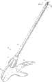
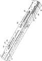
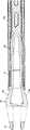
[0047]图1是根据本公开的一个实施方式的手术施夹器的前视立体图;[0047] FIG. 1 is a front perspective view of a surgical clip applier according to one embodiment of the present disclosure;
[0048]图2是图1所示的施夹器的后视立体图,图示了其轴组件的旋转;[0048] FIG. 2 is a rear perspective view of the clip applier shown in FIG. 1 illustrating rotation of its shaft assembly;
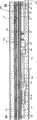
[0049]图3是图1和图2所示的施夹器的轴组件的远端的前视立体图;[0049] FIG. 3 is a front perspective view of the distal end of the shaft assembly of the clip applier shown in FIGS. 1 and 2;
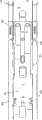
[0050]图4是图1和图2所示的施夹器的俯视图;Fig. 4 is the top view of clip applier shown in Fig. 1 and Fig. 2;
[0051]图5是图1和图2所示的施夹器的侧面正视图;Fig. 5 is a side elevational view of the clip applier shown in Fig. 1 and Fig. 2;
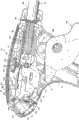
[0052]图6是图1至图5所示的施夹器的手柄组件的立体图,图示了左半壳体被从其中移走的情况;[0052] FIG. 6 is a perspective view of the handle assembly of the clip applier shown in FIGS. 1-5, illustrating the left half-shell being removed therefrom;
[0053]图7是图1至图5所示的施夹器的手柄组件的立体图,图示了右半壳体被从其中移走的情况;[0053] FIG. 7 is a perspective view of the handle assembly of the clip applier shown in FIGS. 1-5, illustrating the right half-shell being removed therefrom;
[0054]图8是图1至图5所示的施夹器的手柄组件的部件分解的立体图;[0054] FIG. 8 is an exploded perspective view of the handle assembly of the clip applier shown in FIGS. 1-5;
[0055]图8A是图6至图8所示的手柄组件在扳机被从其中移走的情况下的立体图;[0055] FIG. 8A is a perspective view of the handle assembly shown in FIGS. 6-8 with the trigger removed therefrom;
[0056]图8B是图6至图8所示的手柄组件的反馈构件的立体图;[0056] FIG. 8B is a perspective view of the feedback member of the handle assembly shown in FIGS. 6-8;
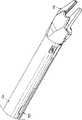
[0057]图9是图1至图5所示的施夹器的轴组件的部件分解的立体图;[0057] FIG. 9 is an exploded perspective view of the shaft assembly of the clip applier shown in FIGS. 1-5;
[0058]图10是图9所示的轴组件的右侧前视立体图,示出了装配的情况;[0058] FIG. 10 is a right side front perspective view of the shaft assembly shown in FIG. 9, shown assembled;
[0059]图11是图10中显示的细节表示区域的放大视图;[0059] FIG. 11 is an enlarged view of the detail representation area shown in FIG. 10;
[0060]图12是图9至图11所示的轴组件的右侧前视图,示出了上壳体被从其中移走的情况;[0060] FIG. 12 is a right side front view of the shaft assembly shown in FIGS. 9-11, showing the upper housing removed therefrom;
[0061]图13是图12中显示的细节表示区域的放大视图;[0061] FIG. 13 is an enlarged view of the detail representation area shown in FIG. 12;
[0062]图14是图12中显示的细节表示区域的放大视图;[0062] FIG. 14 is an enlarged view of the detail representation area shown in FIG. 12;
[0063]图15是图12中显示的细节表示区域的放大视图;[0063] FIG. 15 is an enlarged view of the detail representation area shown in FIG. 12;
[0064]图16是图9至15所示的轴组件的推杆的近端以及弹簧夹子(snapclip)的部件分解的立体图;[0064] FIG. 16 is an exploded perspective view of the proximal end of the pushrod and snap clip of the shaft assembly shown in FIGS. 9 to 15;
[0065]图17是图9至图15所示轴组件的仰视图,图示了推杆的近端以及布置在上壳体中的弹簧夹子;[0065] FIG. 17 is a bottom view of the shaft assembly shown in FIGS. 9-15, illustrating the proximal end of the push rod and the spring clip disposed in the upper housing;
[0066]图18是图9至图17所示的轴组件的右侧前视立体图,示出了上壳体和推杆被从其中移走的情况;[0066] FIG. 18 is a right side front perspective view of the shaft assembly shown in FIGS. 9-17, showing the upper housing and pushrod removed therefrom;
[0067]图19是图18中显示的细节表示区域的放大视图;[0067] FIG. 19 is an enlarged view of the detail representation area shown in FIG. 18;
[0068]图20是图18中显示的细节表示区域的放大视图;[0068] FIG. 20 is an enlarged view of the detail representation area shown in FIG. 18;
[0069]图21是图9至图20所示的轴组件的右侧前视立体图,示出了上壳体、推杆和推进板被从其中移走的情况;[0069] FIG. 21 is a right side front perspective view of the shaft assembly shown in FIGS. 9-20 showing the upper housing, pushrod and pusher plate removed therefrom;
[0070]图22是图21中显示的细节表示区域的放大视图;[0070] FIG. 22 is an enlarged view of the detail representation area shown in FIG. 21;
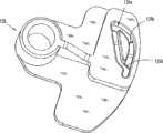
[0071]图23是夹子输出器以及闭锁板的部件分解的立体图;[0071] FIG. 23 is an exploded perspective view of the clip follower and lockout plate;
[0072]图23A是图23所示的夹子输出器以及闭锁板装配完毕后的俯视立体图;Fig. 23A is a top perspective view after the clip output device shown in Fig. 23 and the locking plate are assembled;
[0073]图24是图23所示的夹子输出器的仰视立体图;[0073] FIG. 24 is a bottom perspective view of the clip follower shown in FIG. 23;
[0074]图25是图9至图23所示的轴组件的远端的右侧前视立体图,示出了上壳体、推杆、推进板以及夹子载体被从其中移走的情况;[0074] FIG. 25 is a right side front perspective view of the distal end of the shaft assembly shown in FIGS. 9-23, showing the upper housing, push rod, pusher plate, and clip carrier removed therefrom;
[0075]图26是图25所示的轴组件的远端的右侧前视立体图,示出了上壳体、推杆、推进板、夹子载体以及驱动通道被从其中移走的情况;[0075] FIG. 26 is a right side front perspective view of the distal end of the shaft assembly shown in FIG. 25, showing the upper housing, pushrod, pusher plate, clip carrier, and drive channel removed therefrom;
[0076]图27是图9至图26所示的轴组件的左侧前视立体图,示出了上壳体、推杆、推进板、夹子载体、驱动通道以及楔形板被从其中移走的情况;[0076] FIG. 27 is a left front perspective view of the shaft assembly shown in FIGS. 9-26 showing the upper housing, push rod, pusher plate, clip carrier, drive channel, and wedge plate removed therefrom. Condition;
[0077]图28是图27中显示的细节表示区域的放大视图;[0077] FIG. 28 is an enlarged view of the detail representation area shown in FIG. 27;
[0078]图29是图27中显示的细节表示区域的放大视图;[0078] FIG. 29 is an enlarged view of the detail representation area shown in FIG. 27;
[0079]图30是图9至29所示的轴组件的下壳体的左侧前视立体图;[0079] FIG. 30 is a left front perspective view of the lower housing of the axle assembly shown in FIGS. 9-29;
[0080]图31是图30中显示的细节表示区域的放大视图;[0080] FIG. 31 is an enlarged view of the detail representation area shown in FIG. 30;
[0081]图31A是图30中显示的细节表示区域的放大视图;[0081] FIG. 31A is an enlarged view of the detail representation area shown in FIG. 30;
[0082]图32是图1至31A所示的施夹器的纵向截面图,图示了处于未致动状态下的施夹器;[0082] FIG. 32 is a longitudinal cross-sectional view of the clip applier shown in FIGS. 1-31A, illustrating the clip applier in an unactuated state;
[0083]图33是图32中显示的细节表示区域的放大视图;[0083] FIG. 33 is an enlarged view of the detail representation area shown in FIG. 32;
[0084]图34是图1至图31A所示的施夹器的轴组件的远端的纵向截面图;[0084] FIG. 34 is a longitudinal cross-sectional view of the distal end of the shaft assembly of the clip applier shown in FIGS. 1-31A;
[0085]图35是沿图34中的35-35截取的截面图;[0085] FIG. 35 is a cross-sectional view taken along line 35-35 in FIG. 34;
[0086]图36是图34中显示的细节表示区域的放大视图;[0086] FIG. 36 is an enlarged view of the detail representation area shown in FIG. 34;
[0087]图37是沿图36中的37-37截取的截面图;[0087] FIG. 37 is a cross-sectional view taken along line 37-37 in FIG. 36;
[0088]图38是图34中显示的细节表示区域的放大视图;[0088] FIG. 38 is an enlarged view of the detail representation area shown in FIG. 34;
[0089]图39是沿图38中的39-39截取的截面图;[0089] FIG. 39 is a cross-sectional view taken along line 39-39 in FIG. 38;
[0090]图40是图34中显示的细节表示区域的放大视图;[0090] FIG. 40 is an enlarged view of the detail representation area shown in FIG. 34;
[0091]图41是沿图40中的41-41截取的截面图;[0091] FIG. 41 is a cross-sectional view taken along line 41-41 in FIG. 40;
[0092]图42是图34中显示的细节表示区域的放大视图;[0092] FIG. 42 is an enlarged view of the detail representation area shown in FIG. 34;
[0093]图43是沿图42中的43-43线截取的截面图;[0093] FIG. 43 is a cross-sectional view taken along line 43-43 in FIG. 42;
[0094]图44是图1至43所示的施夹器在最初致动期间的纵向截面图;[0094] FIG. 44 is a longitudinal sectional view of the clip applier shown in FIGS. 1-43 during initial actuation;
[0095]图45是图44中显示的细节表示区域的放大视图;[0095] FIG. 45 is an enlarged view of the detail representation area shown in FIG. 44;
[0096]图46是图34中显示的细节表示区域36的在施夹器的最初致动期间的放大视图;[0096] FIG. 46 is an enlarged view of the
[0097]图47是图34中显示的细节表示区域40的在施夹器的最初致动期间的放大视图;[0097] FIG. 47 is an enlarged view of the
[0098]图47A是推杆的俯视图,图示了推杆在施夹器的最初致动期间的移动;[0098] FIG. 47A is a top view of the push rod illustrating movement of the push rod during initial actuation of the clip applier;
[0099]图47B和图47C均是轴组件的纵向截面图,图示了在施夹器的最初致动期间楔形板的移动;[0099] FIGS. 47B and 47C are each longitudinal cross-sectional views of the shaft assembly illustrating movement of the wedge plate during initial actuation of the clip applier;
[00100]图48和图49是在施夹器的最初驱动期间轴组件沿图40中41-41截取的截面的放大视图;[00100] FIGS. 48 and 49 are enlarged views of a section of the shaft assembly taken along 41-41 in FIG. 40 during initial actuation of the clip applier;
[00101]图50是在施夹器的最初致动期间图34中显示的细节表示区域42的放大视图;[00101] FIG. 50 is an enlarged view of the detail showing region 42 shown in FIG. 34 during initial actuation of the clip applier;
[00102]图51是在施夹器的最初致动期间轴组件的远端的左侧仰视立体图;[00102] FIG. 51 is a left bottom perspective view of the distal end of the shaft assembly during initial actuation of the clip applier;
[00103]图52至图54均是轴组件的纵向截面图,图示了在施夹器的最初致动期间楔形板的进一步移动,以及连接板的杆从楔形板的弹簧夹子的脱离;[00103] FIGS. 52-54 are each longitudinal cross-sectional views of the shaft assembly illustrating further movement of the wedge plate during initial actuation of the clip applier, and disengagement of the rod of the connecting plate from the spring clip of the wedge plate;
[00104]图55是图1至图54所示的施夹器的纵向截面图,图示了在进一步致动期间的施夹器;[00104] FIG. 55 is a longitudinal cross-sectional view of the clip applier shown in FIGS. 1-54, illustrating the clip applier during further actuation;
[00105]图56是图55中显示的细节表示区域的放大视图;[00105] FIG. 56 is an enlarged view of the detail representation area shown in FIG. 55;
[00106]图56A是移去上壳体的轴组件的右视立体图,图示了在施夹器的进一步致动期间推杆的移动;[00106] FIG. 56A is a right perspective view of the shaft assembly with the upper housing removed, illustrating movement of the push rod during further actuation of the clip applier;
[00107]图56B和图56C均是推进板的仰视图,图示了在施夹器的进一步致动期间推进板的移动;[00107] FIGS. 56B and 56C are each a bottom view of the pusher plate illustrating movement of the pusher plate during further actuation of the clip applier;
[00108]图57是在施夹器的进一步致动期间图34中显示的细节表示区域36的放大视图;[00108] FIG. 57 is an enlarged view of the
[00109]图58是在施夹器的进一步致动期间图34中显示的细节表示区域40施夹器的放大视图;[00109] FIG. 58 is an enlarged view of the clip applier in the
[00110]图59和图60是轴组件的纵向截面图,图示了在施夹器的进一步致动期间推杆的移动以及支撑在推杆上的夹子与上壳体的凸台的连接;[00110] FIGS. 59 and 60 are longitudinal cross-sectional views of the shaft assembly illustrating movement of the pushrod and connection of the clip supported on the pushrod to the boss of the upper housing during further actuation of the clip applier;
[00111]图61是在施夹器的进一步致动期间图34中显示的细节表示区域40的放大视图;[00111] FIG. 61 is an enlarged view of the
[00112]图62是在施夹器的进一步致动期间图34中显示的细节表示区域42的放大视图;[00112] FIG. 62 is an enlarged view of the detail showing region 42 shown in FIG. 34 during further actuation of the clip applier;
[00113]图63是轴组件的纵向截面图,图示了在施夹器的进一步致动期间驱动杆的移动;[00113] FIG. 63 is a longitudinal cross-sectional view of the shaft assembly illustrating movement of the drive rod during further actuation of the clip applier;
[00114]图64和图65是在施夹器的进一步致动期间轴组件沿图40中41-41截取的截面的放大视图;[00114] FIGS. 64 and 65 are enlarged views of a section of the shaft assembly taken at 41-41 in FIG. 40 during further actuation of the clip applier;
[00115]图66是在施夹器的进一步致动期间轴组件的远端的俯视左侧立体图;[00115] FIG. 66 is a top left perspective view of the distal end of the shaft assembly during further actuation of the clip applier;
[00116]图67至图69是轴组件的纵向截面图,图示了在施夹器的进一步致动期间连接板的移动;[00116] FIGS. 67-69 are longitudinal cross-sectional views of the shaft assembly illustrating movement of the connecting plate during further actuation of the clip applier;
[00117]图67A至图69A是根据本公开的另一可选实施方式的轴组件的纵向截面图,图示了在施夹器的进一步致动期间连接板的移动;[00117] FIGS. 67A-69A are longitudinal cross-sectional views of a shaft assembly illustrating movement of the connecting plate during further actuation of the clip applier, according to another alternative embodiment of the present disclosure;
[00118]图70是图1至图69所示的施夹器在最后的致动期间的纵向截面图;[00118] FIG. 70 is a longitudinal cross-sectional view of the clip applier shown in FIGS. 1-69 during final actuation;
[00119]图71是图70中显示的细节表示区域的放大视图;[00119] FIG. 71 is an enlarged view of the detail representation area shown in FIG. 70;
[00120]图72是在施夹器的最后致动期间图34中显示的细节表示区域42的放大视图;[00120] FIG. 72 is an enlarged view of the detail showing region 42 shown in FIG. 34 during final actuation of the clip applier;
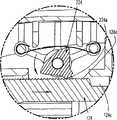
[00121]图73和图74是轴组件的远端的前视立体图,图示了在施夹器的最后致动期间钳口的致动;[00121] FIGS. 73 and 74 are front perspective views of the distal end of the shaft assembly illustrating actuation of the jaws during final actuation of the clip applier;
[00122]图75是图示了施加到脉管上的手术夹子的立体图;[00122] FIG. 75 is a perspective view illustrating a surgical clip applied to a vessel;
[00123]图76是在施夹器的扳机被松开时图70中显示的细节表示区域71的放大视图;[00123] FIG. 76 is an enlarged view of the detail showing area 71 shown in FIG. 70 when the trigger of the clip applier is released;
[00124]图76A是在扳机在其完全致动后松开时手柄组件的侧面正视图;[00124] FIG. 76A is a side elevational view of the handle assembly when the trigger is released after its full actuation;
[00125]图77是轴组件的纵向截面图,图示了在扳机松开期间连接板的移动;[00125] FIG. 77 is a longitudinal cross-sectional view of the shaft assembly illustrating movement of the connecting plate during trigger release;
[00126]图78是轴组件的纵向截面图,图示了在扳机的松开期间推杆的移动以及支撑在推杆上的夹子从上壳体的凸台的脱开;[00126] FIG. 78 is a longitudinal sectional view of the shaft assembly illustrating movement of the push rod and disengagement of the clip supported on the push rod from the boss of the upper housing during release of the trigger;
[00127]图79是移去上壳体的轴组件的右视立体图,图示了在扳机的松开期间推杆的移动;[00127] FIG. 79 is a right perspective view of the shaft assembly with the upper housing removed, illustrating movement of the push rod during release of the trigger;
[00128]图80是在扳机松开期间图34中显示的细节表示区域40的放大视图;[00128] FIG. 80 is an enlarged view of the
[00129]图81是轴组件的纵向截面图,图示了在扳机松开期间连接板的杆再次连接到推杆的弹簧夹子上;[00129] FIG. 81 is a longitudinal sectional view of the shaft assembly illustrating the reconnection of the rod of the connecting plate to the spring clip of the push rod during trigger release;
[00130]图82至图83均是轴组件的纵向截面图,图示了在扳机松开期间楔形板的进一步移动以及连接板的杆与楔形板的弹簧夹子上的再次接合;[00130] FIGS. 82-83 are each longitudinal cross-sectional views of the shaft assembly illustrating further movement of the wedge plate and re-engagement of the rod of the connecting plate with the spring clip of the wedge plate during trigger release;
[00131]图84是当施夹器处于闭锁状态时轴组件的远端的前视立体图;[00131] FIG. 84 is a front perspective view of the distal end of the shaft assembly when the clip applier is in the locked state;
[00132]图85是当施夹器处于闭锁状态时图34显示的细节表示区域42的放大视图;以及[00132] FIG. 85 is an enlarged view of the detail showing region 42 shown in FIG. 34 when the clip applier is in the locked state; and
[00133]图86是当施夹器处于闭锁状态时图70显示的细节表示区域71的放大视图。[00133] FIG. 86 is an enlarged view of the detail showing area 71 shown in FIG. 70 when the clip applier is in the locked state.
具体实施方式Detailed ways
[00134]现将参照附图详细说明根据本公开的手术施夹器的实施方式,附图中相似的附图标记表示相似或相同的部件。如图所示及以下说明书通篇所描述的,按照传统,当涉及手术器械上的相对位置时,术语“近侧”指装置的靠近用户的一端,术语“远侧”指装置的远离用户的一端。[00134] Embodiments of surgical clip appliers according to the present disclosure will now be described in detail with reference to the accompanying drawings, in which like reference numerals indicate similar or identical components. As shown in the figures and described throughout the following specification, by convention, when referring to relative positions on a surgical instrument, the term "proximal" refers to the end of the device that is closer to the user, and the term "distal" refers to the end of the device that is remote from the user. one end.
[00135]现参照图1至图5,根据本公开的一个实施例的手术施夹器总体上用100来指代。施夹器100包括手柄组件102和内窥镜部,该内窥镜部包括从手柄组件102向远侧延伸的轴组件104。[00135] Referring now to FIGS. 1-5 , a surgical clip applier is generally designated 100 in accordance with one embodiment of the present disclosure.
[00136]轴组件104具有约10mm的外径。取决于预计的用途诸如肥胖病手术,轴组件104可以具有各种伸长的或缩短的长度。[00136]
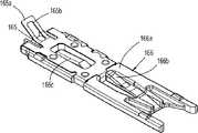
[00137]如图1至图5所示,手术施夹器100包括安装在轴组件104的远端并可由手柄组件102的扳机108致动的一对钳口106。一对钳口106由合适的生物相容的材料诸如不锈钢或钛制成,该一对钳口限定了在其之间用于将手术夹子“C”容纳在其中的通道106a。当一对钳口106处于相对于彼此打开或非接近的状态时,测得一对钳口106的宽度大于轴组件104的外径。[00137] As shown in FIGS. A pair of
[00138]一对钳口106安装于轴组件104的远端以使它们相对该处纵向固定。旋钮110可以可旋转地安装在手柄组件102的远端,并连接于轴组件104以向轴组件104和一对钳口106传输和/或提供绕其纵轴的360°旋转(参见图2)。[00138] A pair of
[00139]现参照图1至图8,示出了手术施夹器100的手柄组件102。手柄组件102包括壳体103,该壳体具有第一或右侧半部103a和第二或左侧半部103b。手柄组件102包括可枢转地支撑在右侧半部103a和左侧半部103b之间的扳机108。如以下将更详细讨论的,手柄组件102限定了形成于壳体103中的用于支撑和显示计数机构的窗口103c。手柄组件102的壳体103可由合适的塑料制成。[00139] Referring now to FIGS. 1-8, a
[00140]壳体103将驱动组件120支撑在右侧半部103a和左侧半部103b之间。驱动组件120包括叉形连杆122,该叉形连杆具有枢转地连接于扳机108的第一端和枢转地连接于曲柄板124的第二端。如图6至图9所示,驱动组件120进一步包括可旋转地连接于曲柄板124的驱动连接器134、与驱动连接器134相互连接的柱塞135和支撑在驱动连接器134上的弹簧136。柱塞135限定了纵向狭槽135a,该纵向狭槽配置成并适于将驱动杆140的近端容纳在其中。[00140]
[00141]驱动杆140通过整体销135b连接于柱塞135(参见图9)。设置了帽144,柱塞135贯穿该帽。设置密封件(seal)(未示出)来建立柱塞135和外管150之间的气密性密封。[00141] The
[00142]如图6至图8所示,手柄组件102进一步包括形成于曲柄板124中/上的齿条124a以便齿条124a可随曲柄板124移动。齿条124a包括置于曲柄板124中限定的远侧凹槽124b和近侧凹槽124c之间的多个齿。设置凹槽124b和124c以允许棘爪224转并当曲柄板124在近侧和远侧移动之间变化时提升至齿条124a的齿上。[00142] As shown in FIGS. 6-8, the
[00143]手柄组件102进一步包括棘爪224,在棘爪224与曲柄板124的齿条124a大体上操作的接合的位置处,棘爪224通过棘爪销226枢转地连接于壳体103。棘爪224包括棘爪齿224a,该棘爪齿可选择地与曲柄板124的齿条124a的齿接合。棘爪齿224a可与齿条齿接合以限制齿条124a并且依次地限制曲柄板124在手柄组件102内的纵向移动。设置爪簧228以使棘爪224偏入到与曲柄板124的齿条124a操作的接合。[00143] The
[00144]如图6至图8所示,曲柄板124通过销123可枢转地连接于叉形连杆122。曲柄板124限定了形成于其中的一系列棘轮齿124a以与棘爪224选择的接合。[00144] As shown in FIGS. Crank
[00145]如图8、图8A和图8B所示,手柄组件102进一步包括听觉/触觉反馈构件126,该反馈构件与扳机108操作地相关以便与其一起旋转并且当扳机108致动时绕着共同的轴旋转。反馈构件126限定了滚道126a,滚道126a限定了多个棘轮齿或梯级126b。设置有可偏转臂127,该可偏转臂包括操作的连接或布置在反馈元件126的滚道126a中并与梯级126b接触的第一端和连接于壳体103的第二端。在操作中,当致动扳机108时,臂127通过和/或沿着形成于反馈构件126中的滚道126a移动。如以下将更详细讨论的,随着臂127在反馈构件126的梯级126b上移动,臂127弹锁住梯级126b,并产生可听到的声音/喀哒声和/或可感觉到的振动。[00145] As shown in FIGS. 8, 8A and 8B, the
[00146]听觉/触觉反馈构件126包括足够的梯级126b以便在夹子已经被完全装入手术施夹器100的钳口中后、在装入的夹子已经由手术施夹器100钳口形成后、并且当手术施夹器100被复位到原位并准备发射/形成另一夹子时产生听觉/触觉指示。[00146] The audible/
[00147]如图6、图7、图8和图8A所示,手术施夹器100的手柄组件102进一步包括支撑在壳体103中并通过限定在壳体103中的窗口103c可见的计数机构132。计数机构132包括显示器132a、处理器132b和使用电池等形式的能源(未示出)。[00147] As shown in FIGS. 6, 7, 8 and 8A, the
[00148]显示器132a可以是本领域已知的任何器件以提供事件的指示。事件可以涉及施夹器100的程序或操作。显示器132a是液晶显示器(LCD)。[00148]
[00149]显示器132a向外科医生显示施夹器100的一个或多个操作参数。由显示器132a显示的操作参数包括剩下的夹子的数量(amount)或数目(number)、已经使用的夹子的数目、位置参数、使用的手术时间或程序的任何其它参数。[00149]
[00150]在电池或能源和处理器132b的触头之间布置聚酯薄膜(Mylar)或另一聚合绝缘材料,该材料防止电池或能源在存储过程中被耗尽。凸起从手术施夹器100的壳体103伸出以允许凸起易于从那里移开。一旦凸起被移开,电池或能源与处理器132b的触头电接触,而使显示器132a通电。[00150] Mylar or another polymeric insulating material is disposed between the battery or energy source and the contacts of the
[00151]如图6、图7、图8和图8A所示,手术施夹器100的手柄组件102进一步包括计数致动机构,该机构包括具有配置成并适于操作地、选择性地接合计数机构132的处理器132b的计数致动杠杆130。计数致动杠杆130进一步包括第二臂130b,该臂配置成并适于操作地、可滑动地接合形成在致动板128中的狭槽128a,致动板128可滑动地支撑在壳体103中。[00151] As shown in FIGS. 6, 7, 8, and 8A, the
[00152]在操作中,如以下将更详细说明的,随着扳机108被挤压,扳机108使得叉形连杆122向远侧推进,使得曲柄板124向远侧推进。当曲柄板124的臂124d推进预定距离时,臂124d接合或接触致动板128的指部128b。随着曲柄板124进一步向远侧推进,曲柄板124向远侧方向推动或拉动触发板128,从而致动计数致动杠杆130以致动计数机构132。[00152] In operation, as will be described in more detail below, as the
[00153]特别地,当致动板128向远侧移动足够的距离时,在其狭槽128b内用凸轮带动计数致动杠杆130的第二臂130b并使计数致动杠杆130旋转导致第一臂130a旋转。当致动板128向近侧移动足够的距离时,计数致动杠杆130的第二臂130b返回原位,导致计数致动杠杆130的第一臂130a脱离计数机构132。[00153] Particularly, when the
[00154]现转至图9至图31A,手术施夹器100的轴组件104被示出并在下文中加以描述。轴组件104及其组件可由合适的生物相容的材料诸如不锈钢、钛、塑料等制成。轴组件104包括外管150,外管150具有支撑在壳体103内的近端150a、远端150b和贯穿其中的内腔150c。外管150通过从其外表面突出的凸缘被固定在壳体103内。轴组件104进一步包括均布置在外管150的内腔150c内的上壳体152a和下壳体152b。后部上壳体154布置在外管150内和上壳体152a的近侧。[00154] Turning now to FIGS. 9-31A, the
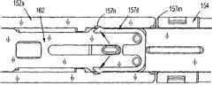
[00155]如图9、图12和图13所示,轴组件104进一步包括可滑动地布置在上壳体152a和后部上壳体154内的推杆156。推杆156包括限定了窄形推动器156c的远端156a,推动器156c配置成并适于选择性地接合/移动(即向远侧推进)一堆夹子“C”的最远侧的夹钳“C1”,并在其最初形成期间与最远侧的夹钳“C1”保持接触。推杆156进一步包括近端156b。推杆156限定了具有窗钩156e的远侧窗口156d、位于远侧窗口156d的近侧并形成在其每侧边缘的一对凹槽156f、位于侧凹槽156f的近侧的细长狭槽156g和位于狭槽156g的近侧的最近侧窗口156h。[00155] As shown in FIGS. 9, 12 and 13, the
[00156]如图9和图14所示,推杆156在侧凹槽156f的远侧位置处沿着推杆156的上表面支撑第一弹簧夹子157a。第一弹簧夹子157a以这样的方式配置:其尖头突出或与推杆156的上表面间隔一定量。[00156] As shown in FIGS. 9 and 14, the
[00157]如图9和图15所示,推杆156在其最近侧窗口156h的近侧位置处沿着推杆156的下表面支撑第二弹簧夹子157b。第二弹簧夹子157b以这样的方式定位:其尖头突出足以压在推杆156的最近侧窗口156h上的量。第二弹簧夹子157b的尖头彼此隔开一定量,该量小于推杆156的最近侧窗口156h的宽度。[00157] As shown in FIGS. 9 and 15, the
[00158]如图9和图16至图20所示,轴组件104进一步包括可往复运动地支撑在推杆156下方的推进板162。如图16和图17所示,第四弹簧夹子157d支撑在推进板162的近端。弹簧夹子157d包括一对尖头,该尖头可拆卸地连接于形成于上壳体152a中的近侧保持槽152m和远侧保持槽152n。这样,在使用中,弹簧夹子157d可拆卸地接合保持槽152m和远侧保持槽152n以使推进板162保持在近侧或远侧位置。在推进板162向远侧推进时,用凸轮向内带动弹簧夹子157d的尖头并使得推进板162继续向远侧移动。[00158] As shown in FIGS. 9 and 16-20, the
[00159]如图18至图20所示,推进板162包括形成于其中并沿着其长度延伸的一系列窗口162a。如图19所示,每个窗口162a限定了近侧边缘,该边缘在推进板162的表面下方延伸以便限定唇缘或凸耳162c。推进板162进一步包括一对侧翼片162b,该侧翼片从其侧边缘在朝着上壳体152a的方向上延伸。如图15所示,一对侧翼片162b可滑动地布置在推杆156的侧凹槽156f中。[00159] As shown in FIGS. 18-20, the
[00160]如图9和图21至图22所示,轴组件104进一步包括布置在上壳体152a中并位于推进板162下方的夹子载体164。夹子载体164一般是具有上壁、一对侧壁和限定通过其的通道的下壁的盒状结构。夹子载体164包括形成于下壁中并沿着其长度纵向延伸的多个隔开的窗口164a(参见图9)。夹子载体164包括形成于上壁中并沿着其长度纵向延伸的细长窗口。[00160] As shown in FIGS. 9 and 21-22, the
[00161]如图9和图21所示,一堆手术夹子“C”被以便于在其中和/或沿其滑动的方式装入和/或保持在夹子载体164的通道中。夹子载体164的通道配置并定尺寸成以头对尾的方式可滑动地保持一堆或多个手术夹子“C”。[00161] As shown in FIGS. 9 and 21, a stack of surgical clips "C" is loaded and/or retained in the channel of the
[00162]如图19所示,夹子载体164的远端包括一对隔开的弹性柄脚164b。柄脚164b配置成并适于可拆卸地接合保持在夹子载体164内的该堆手术夹子“C”的最远侧手术夹子“C1”的后跨部(backspan)。[00162] As shown in FIG. 19, the distal end of the
[00163]如图9和图21至图24所示,施夹器100的轴组件104进一步包括可滑动地布置在夹子载体164的通道内的夹子输出器166。如以下将更详细说明的,夹子输出器166位于该堆手术夹子“C ”的后方并设置为在施夹器100的致动期间向前推动该堆夹子“C”。如将在下文中更详细说明的,夹子输出器166通过推进板162的向前和向后往复移动来致动。[00163] As shown in FIGS. 9 and 21-24, the
[00164]如图23、图23A和图24所示,夹子输出器166包括主体部166a、大体上从主体部166a向上和向后延伸的远侧凸起166b、及大体上从主体部166a向下和向后延伸的近侧凸起166c。[00164] As shown in Fig. 23, Fig. 23A and Fig. 24, the
[00165]夹子输出器166的远侧凸起166b配置并定尺寸成选择性地接合推进板162的窗口162a的凸耳162c。在使用中,随着推进板162向远侧方向推进或移动,夹子输出器166的远侧凸起166b面向推进板162的窗口162a的凸耳162c的接合使得夹子输出器166朝着远侧方向逐步推进或行进。[00165] The
[00166]近侧凸起166c配置并定尺寸成选择性地接合形成在夹子载体164中的窗口164a。在使用中,夹子输出器166的近侧凸起166c在形成夹子载体164的窗口164a中的接合防止夹子输出器166向近侧方向行进或移动。[00166]
[00167]夹子输出器166包括支撑在其上或可选择地与其整体形成的闭锁板165。闭锁板165包括以从夹子输出器166的主体部166a向上和向后的方向从闭锁板165延伸的弹性尾部165a,该弹性尾部限定了窗口165b。[00167]
[00168]如图9、图25和图38所示,轴组件104进一步包括在夹子载体164下方的位置处可往复运动地支撑在通道组件104中的驱动通道168。驱动通道168是大体U形的通道,该通道包括从其后跨部168c在离开夹子载体164并朝着下壳体152b的方向上延伸的一对隔开的侧壁168b。驱动通道168进一步包括在狭槽168a的近侧的位置处从后跨部168c突出并在侧壁168b的方向上延伸的凸起168d。如图41所示,驱动通道168限定了形成于侧壁168b中的一个侧壁中的狭槽或窗口168e以选择性地容纳楔形板释放装置194的齿194c。[00168] As shown in FIGS. 9, 25 and 38, the
[00169]如图9和图25所示,施夹器100的轴组件104包括固定到驱动通道168上的驱动通道带箍167。带箍167固定到驱动通道168的侧壁168b上以便横跨驱动通道168的侧壁168b横向延伸。带箍167在细长槽168a的远侧位置处固定到驱动通道168上。带箍167固定到驱动通道168上以使楔形板172在驱动通道168的后跨部168c和钳口106之间延伸。[00169] As shown in FIGS.
[00170]如图9、图26和图27所示,施夹器100包括安装在轴组件104上或安装在轴组件104的远端处并可由扳机108致动的一对钳口106。钳口106由合适的生物相容性材料诸如不锈钢或钛形成。[00170] As shown in FIGS.
[00171]通过形成于下壳体152b中的与形成于钳口106中的容纳狭槽接合的凸台,将钳口106安装在邻近驱动通道168的远端,以使钳口106相对于驱动通道168保持固定。如图25所示,钳口106限定了在其之间用于将手术夹子“C”容纳在其中的通道106a。[00171] The
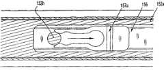
[00172]如图9、图25和图26所示,施夹器100的轴组件104进一步包括楔形板172,楔形板172具有置于驱动通道168和钳口106之间的远端和贯穿轴组件104的近端。楔形板172包括大体锥形的远端172a以在钳口106之间选择性的操作的插入。如图26所示,楔形板172限定了从其下表面突出的翼片或凸起172b。如图22所示,楔形板172限定了形成在其中的最远侧狭槽172c以将连接板174的第二杆174c可滑动地容纳在其中。[00172] As shown in FIGS. 9, 25, and 26, the
[00173]如图22所示,第三弹簧夹子157c支撑在楔形板172的近端处。第三弹簧夹子157c以这样的方式定位:其尖头突出足以压在形成于楔形板172中的最近侧窗口172c上的量。第三弹簧夹子157c的尖头彼此隔开一定量,该量小于楔形板172的最近侧窗口172c的宽度。[00173] As shown in FIG. 22, the
[00174]如图9、图18、图20和图36所示,施夹器100的轴组件104进一步包括连接板174,连接板174可滑动地置于推杆156和楔形板172之间并且可拆卸地可连接于推杆156和楔形板172中的每一个。连接板174包括锥形远端174a、从其上表面延伸的第一杆174b和从其下表面延伸的第二杆174c。杆174b、174c中的每一个均具有大体泪珠形的轮廓,其中杆174b、174c中的每一个的远端均大于其近端。[00174] As shown in FIGS. 9, 18, 20 and 36, the
[00175]在操作中,连接板174的第一杆174b配置并定尺寸成与固定到推杆156上的第二弹簧夹子157b可拆卸的连接,连接板174的第二杆174c配置并定尺寸成与固定到楔形板172上的第三弹簧夹子157c可拆卸的连接。[00175] In operation, the
[00176]如图22、图36和图37所示,连接板174的第二杆174c延伸到限定在驱动杆140的窗口140b中。这样,随着驱动杆140往复运动,连接板174随其往复运动。[00176] As shown in FIGS. Thus, as the
[00177]如图31A所示,保护装置198被支撑在下壳体152b中在其最初远侧推进期间在便于保持第三弹簧夹子157c的尖头之间的相对距离的位置处。这样,连接板174的第二杆174b不能过早地脱离第三弹簧夹子157c直到第三弹簧夹子157c已经越过保护装置198。[00177] As shown in FIG. 31A, the
[00178]如图9、图27、图29和图41所示,施夹器100的轴组件104进一步包括可滑动地支撑在下壳体152b的通道中的滑动接头180。滑动接头180包括主体部182和从其延伸的杆184。当合适地定位在下壳体152b的通道中时,滑动接头180的杆184在大体远侧的方向上延伸。滑动接头180的杆184可滑动地通过形成在下壳体152b中并从下壳体152b的通道延伸的短轴152d(参见图29)。轴组件104进一步包括偏置构件186,该偏置元件以压缩弹簧的形式支撑在杆184上并置于下壳体152b的短轴152d和滑动接头180的主体部182之间。[00178] As shown in FIGS. 9, 27, 29 and 41, the
[00179]滑动接头180的主体部182包括凸台182a,该凸台靠近主体部182的近端形成,且配置成并适于在驱动杆140的细长狭槽140a中可滑动的接合(参见图29)。滑动接头180的主体部182进一步包括窝眼182b,该窝眼靠近主体部182的远端形成,且配置成并适于将驱动通道168的凸起168d容纳在其中(参见图38和图39)。[00179] The
[00180]如图9、图27和图28所示,施夹器100的轴组件104进一步包括可滑动地支撑在下壳体152b的通道中和驱动通道168中的楔形板锁190。楔形板锁190包括主体部190a、从主体部190a向远侧延伸的杆190b、从主体部190a向近侧延伸的尾部190c、形成于主体部190a的上表面中的窝眼190d和从尾部190c延伸的杆或齿190e。轴组件104进一步包括偏置构件192,该偏置构件以压缩弹簧的形式支撑在杆190b上并置于下壳体152b和楔形板锁190的主体部190a之间。[00180] As shown in FIGS. 9, 27 and 28, the
[00181]施夹器100的轴组件104进一步包括可旋转地支撑在下壳体152b的通道中的楔形板释放装置194。楔形板释放装置194包括杆194a,该杆配置为与从楔形板锁190的尾部190c延伸的齿190e接合;槌194b,该槌在朝着楔形板锁190的尾部190c的方向上从杆194a向外延伸;及齿194c,该齿在离开楔形板锁190的尾部190c的方向上从杆194a向外延伸。[00181] The
[00182]现将对操作手术施夹器100以在诸如脉管的目标组织的周围形成或卷曲手术夹子进行描述。参照图32至图43,表示在任何操作或使用之前的手术施夹器100。如图32和图33所示,在使用或发射施夹器100之前,扳机108一般处于非承压或非致动状态。这样,驱动组件120的曲柄板124处于缩回或最近侧的位置,因此,柱塞135和驱动杆140也处于缩回位置。当曲柄板124处于缩回位置时,棘爪224布置在限定在曲柄板124中的远侧凹槽124b中。[00182] Operation of
[00183]如图35至图37所示,当驱动组件120和驱动杆140处于缩回位置时,连接板174位于缩回或最近侧位置。当连接板174位于缩回或最近侧位置时,推杆156也处于缩回或最近侧位置,连接板174的第一泪珠形杆174b布置在推杆156的最近侧窗口156h的近端并保持与第二弹簧夹子157b的尖头搭扣配合的接合。并且,当连接板174位于缩回或最近侧位置时,楔形板172也位于缩回或最近侧位置,且连接板174的第二泪珠形杆174c布置在楔形板172的最近侧窗口172c的近端,并保持与第三弹簧夹子157c的尖头搭扣配合的接合。[00183] As shown in FIGS. 35-37, when the
[00184]如图36和图37所示,当驱动组件120和驱动杆140处于缩回位置时,滑动接头182的凸起182a位于驱动杆140的细长狭槽140a中的最远侧位置处。[00184] As shown in FIGS. 36 and 37, when the
[00185]如图38和图39所示,当驱动组件120和驱动杆140处于缩回位置时,夹子输出器166位于夹子载体164的通道的最近端,其中夹子输出器166的远侧凸起166b操作地布置在推进板162的最近侧窗口162a中,近侧凸起166c操作地布置在夹子载体164的最近侧窗口164a中。[00185] As shown in FIGS. 38 and 39, when the
[00186]继续参照图38和图39,当驱动组件120和驱动杆140处于缩回位置时,滑动接头180位于最近侧位置,并且因为驱动通道168的凸起168d布置在滑动接头180的窝眼182b中,所以驱动通道168也位于最近侧位置。如图38和图39所示,滑动接头180紧靠从下壳体152b突出的物理止挡152e(参见图30)。[00186] With continued reference to FIGS. 38 and 39, when the
[00187]如图40和图41所示,当驱动组件120和驱动杆140处于缩回位置时,楔形板锁190位于最近侧位置以使从其尾部190c延伸的齿190e布置在形成于下壳体152b中的倾斜凸耳152f的近侧(参见图30和图31)。如图41所示,楔形板锁190紧靠从下壳体152b突出的物理止挡152g。同样如图41所示,楔形板释放装置194布置在第一位置处以便其齿194c突入到形成于驱动通道168的侧壁168b中的窗口168e中。[00187] As shown in FIGS. 40 and 41, when the
[00188]如图42和图43所示,当驱动组件120和驱动杆140处于缩回位置时,推杆156的推动器156c布置在保持在夹子载体164中的最远侧夹子“C”的后跨部的近侧。最远侧夹子“C”通过其柄脚164b保持在夹子载体164的通道中。并且,如上所述,在此位置处,楔形板172位于最近侧位置以便其远端172a位于钳口106的近侧。[00188] As shown in FIGS. 42 and 43, when the
[00189]如图43所示,当驱动通道168位于最近侧位置时,其远端从钳口106的近侧凸轮表面106b脱离。[00189] As shown in FIG. 43, when the
[00190]现转到图44至图54,在初始行程的第一阶段中,随着扳机108从初始位置被挤压或致动,扳机108使得叉形连杆122向着远侧方向移动曲柄板124,而这将使得驱动连接器134和柱塞135向远侧移动并使得驱动杆140向远侧移动。当随着柱塞135向远侧移动,弹簧136被压缩初始量。[00190] Turning now to FIGS. 44-54, during the first stage of the initial stroke, the
[00191]与此同时,随着曲柄板124向远侧移动,齿条124a的齿与棘爪224的齿224a接合,棘爪224移出或旋转出曲柄板124的远侧凹槽124a。这样,在没有完成完整的远侧行程的情况下,曲柄板124不能回到最近侧位置。[00191] At the same time, as the
[00192]如图44所示,随着扳机108被挤压初始量,臂127开始平移通过反馈构件126的滚道126a。[00192] As shown in FIG. 44, as the
[00193]如图46所示,随着驱动杆140向着远侧方向移动,驱动杆140向着远侧方向推动连接板174。因为推杆156通过第二弹簧夹子157b选择性地连接于连接板174,推杆156被向着远侧方向推进或拉动。并且,因为楔形板172通过第三弹簧夹子157c选择性地连接于连接板174,楔形板172也被向着远侧方向推进或拖动。[00193] As shown in FIG. 46, as the
[00194]随着驱动杆140向着远侧方向移动,其细长狭槽140a也向着远侧方向移动以使滑动接头182的凸起182a在相对于其的近侧方向上平移。[00194] As the
[00195]如图47至图49所示,随着楔形板172向着远侧方向移动,因为楔形板172的凸起172b保持在楔形板锁190的窝眼190d中,楔形板锁190被向着远侧方向移动或拖动,这使得其尾部190c的齿190e被用凸轮带动越过形成于下壳体152b中的倾斜凸耳152f,从而从倾斜凸耳152f的近侧位置移动到倾斜凸耳152f的远侧位置。随着楔形板锁190向着远侧方向移动,偏置构件192被压缩初始量。如图49所示,楔形板锁190向着远侧方向移动直至楔形板锁190紧靠形成于下壳体152b中的物理止挡。[00195] As shown in FIGS. 47-49, as
[00196]如图47A所示,随着推杆156向着远侧方向移动,推进板162的翼片162b在推杆156的侧凹槽156f中平移预定距离,直到翼片162b接触或接合推杆156的侧凹槽156f的近端。[00196] As shown in FIG. 47A, as
[00197]如图47B和图47C所示,随着楔形板172向着远侧方向移动,由于连接板174的第二杆174c与第三弹簧夹子157c的连接,通过保护装置防止了连接板174的第二杆174c过早地从第三夹钳157c脱离。特别地,随着连接板174向着远侧方向移动,保护装置198作用于第三弹簧夹子157c的尖头的尖端以防止尖头由于第二杆174c所产生的远侧力作用于其上的力而向外张开。[00197] As shown in FIGS. 47B and 47C, as the
[00198]如图50所示,随着推杆156向着远侧方向移动,其推动器156c接合最远侧夹子“C”的后跨部并开始向着远侧方式推动最远侧夹子“C”。随着推杆156向着远侧方向移动最远侧夹子“C”,最远侧夹子“C”从夹子载体164的柄脚164b的后方脱离并开始进入到钳口106的通道106a中。[00198] As shown in FIG. 50, as the
[00199]如图51所示,随着楔形板172向着远侧方向移动,其远端172a进入钳口106之间,使得钳口106向外张开。[00199] As shown in FIG. 51, as the
[00200]如图52至图54所示,一旦楔形板锁190紧靠形成于下壳体152b中的物理止挡,则防止了楔形板172向着远侧方向进一步移动。然而,驱动杆140继续向着远侧方向移动连接板174。因为连接板174被继续向远侧推动,所以一旦第三弹簧夹子157c的尖头的尖端向远侧移动到超过保护装置198,则作用于第二杆174c上的力足够使得第三弹簧夹子157c的尖头向外张开并使得第二杆174c从其间脱开,从而使得连接板174继续向着远侧方向移动。[00200] As shown in FIGS. 52-54, once
[00201]现转到图55至图69,随着扳机108从初始行程的第一阶段被进一步挤压或致动通过初始行程的第二阶段,扳机108使得叉形连杆122进一步向着远侧方向移动曲柄板124,而这使得驱动连接器134并随后使得柱塞135进一步向远侧移动且进一步向着远侧移动驱动杆140。随着柱塞135向远侧移动,弹簧136被压缩进一步的量。[00201] Turning now to FIGS. 55-69, as the
[00202]与此同时,随着曲柄板124向着远侧移动,其齿条124a的齿相对于棘爪224的齿224a进一步向着近侧移动。这样,在没有完成完整的远侧行程的情况下,曲柄板124仍不能返回到最近侧位置。[00202] At the same time, as the
[00203]如图55所示,随着曲柄板124向着远侧移动预定距离之后,其臂124d接合或接触致动板128的指部128b。随着曲柄板124进一步向着远侧推进,曲柄板124向着远侧方向推动或拉动致动板128,从而致动计数致动杠杆130以激活计数机构132。[00203] As shown in FIG. 55, as crank
[00204]特别地,当致动板128向着远侧移动足够距离时,在其槽128b中用凸轮带动计数致动杠杆130的第二臂130b并促使其旋转,导致计数致动杠杆130的第一臂130a接合计数机构132,从而实现其显示器中的变化。特别地,显示手术施夹器100中剩余的夹子的数目的显示器将减少一个。可选择地,夹子计数机构将增加一个或产生某些其他变化。[00204] Particularly, when the
[00205]随着扳机108被进一步挤压时,臂127继续平移通过反馈构件126的滚道126a。在这一点上,在扳机108的挤压中,手术夹子被装入钳口106中。相应地,臂127将与形成于反馈构件126的滚道126a中的梯级126b相互作用并产生告知用户夹子已被装入钳口中的听觉/触觉指示。[00205]
[00206]如图57所示,随着驱动杆140向着远侧方向进一步移动,驱动杆140继续向着远侧方向推动连接板174。因为推杆156仍通过第二弹簧夹子157b选择性地连接于连机板174,所以推杆156被进一步向着远侧方向推进或拖动。然而,因为楔形板172的第三弹簧夹子157c被从连接板174的第二杆174c脱离,所以楔形板172不被向着远侧方向进一步推进或拖动。[00206] As shown in FIG. 57, as the
[00207]如图56A至图56C所示,随着推杆156向着远侧方向继续移动,推杆156的侧凹槽156f的近端接合推进板162的一对翼片162b,推杆156向着远侧方向推进或拖动推进板162。[00207] As shown in FIGS. 56A to 56C, as the
[00208]如图56B和图56C所示,随着推动板162向着远侧推进,弹簧夹子157d脱离近侧保持槽152m并接合形成于上壳体152a中的远侧保持槽152n。[00208] As shown in FIGS. 56B and 56C, as
[00209]如图57所示,驱动杆140向着远侧方向移动,直到滑动接头182的凸起182a选择性地平移至驱动杆140的细长狭槽140a中的最近侧位置。[00209] As shown in FIG. 57, the
[00210]随着推杆156继续向着远侧方向移动,推杆156通过翼片162b继续向着远侧方向推动推进板162。如图58所示,随着推进板162向着远侧方向移动,夹子输出器166的远侧凸起166b被容纳夹子输出器166的远侧凸起166b的窗口162a的近侧边缘接合以便相对于夹子载体164向着远侧方向推动夹子输出器166,从而使该堆夹钳“C”推进增加的量。随着夹子输出器166向着远侧方向移动,使得其近侧凸起166c从夹子载体164的相对近侧窗口164a到夹子载体164的相对远侧窗口164a向远侧推进一个窗口164a。[00210] As the
[00211]如图58至图60所示,随着推杆156向着远侧方向移动,支撑于推杆156上的第一弹簧夹子157a弹锁在上壳体152a的凸台152h上,因而将推杆156保持在向前的位置处。[00211] As shown in FIGS. 58 to 60, as the
[00212]此外,如图61所示,随着推杆156继续向着远侧方向移动,使得该堆夹钳“C”向着远侧方向移动。[00212] Additionally, as shown in FIG. 61, as the
[00213]如图62所示,随着推杆156向着远侧方向移动,其推动器156c继续向着远侧方向移动最远侧夹子“C1”直到最远侧夹子“C1”完全进入到钳口106的通道106a中。在操作中,推杆156的推动器156c在所述夹子“C”的形成期间与装入的夹子“C”的后跨部保持接触以便为其提供稳定性并将其保持在合适的位置。[00213] As shown in FIG. 62, as the
[00214]如图63所示,随着驱动杆140进一步向着远侧方向移动,其肩部140c接触驱动通道168的最近端。这样,随着驱动杆140进一步向着远侧方向移动,驱动杆140向着远侧方向移动或推动驱动通道168。[00214] As shown in FIG. 63, as the
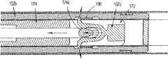
[00215]如图64所示,随着驱动通道168向着远侧方向移动,形成于驱动通道168的侧壁168b中的窗口168e的近侧边缘接触楔形板释放装置194的齿194c,使得楔形板释放装置194旋转。随着楔形板释放装置194旋转,其槌194b挤压楔形板锁190的齿190e以将齿190e从倾斜凸耳152f的后方推出或撞出。在这种情况下,如图65所示,允许偏置构件192减压,从而向着近侧方向移动楔形板锁190。如图66所示,随着楔形板锁190向着近侧方向移动,因为楔形板172连接到楔形板锁190上,所以楔形板172向着近侧方向移动以使其远端172a从与钳口106退出脱离接合。[00215] As shown in FIG. 64, as the
[00216]如图58和图67至图69所示,因为推杆156通过第一弹簧夹子157a与凸台152h的连接而保持在远侧位置,所以随着驱动杆140进一步向着远侧方向移动,作用于连接板174的力使得第二弹簧夹子157b从连接板174的第一杆174b脱离,从而允许连接板174继续向着远侧方向移动。[00216] As shown in FIGS. 58 and 67-69, because the
[00217]如图67A至图69A所示,在一个实施方式中,第二弹簧夹子157b的尖头的尖端可以配置成向外突出以便接合后上部壳体154的表面(参见图9),从而防止第二弹簧夹子157b从连接板174的第一杆174b的过早脱离。在该实施方式中,凹槽可以形成于后部上壳体154的表面中,与第二弹簧夹子157b的尖头可能向外张开的位置一致,从而允许连接板174的第一杆174b脱离并继续向着远侧方向移动。[00217] As shown in FIGS. 67A-69A, in one embodiment, the tip of the prong of the
[00218]如图70至图75所示,随着扳机108被致动进入初始行程的最后阶段,扳机108使得叉形连杆122进一步向着远侧方向移动曲柄板124,而这使得驱动连接器134和柱塞135进一步向着远侧移动并进一步向着远侧移动驱动杆140。随着驱动连接器134向着远侧移动,弹簧136被压缩进一步的量。[00218] As shown in FIGS. 70-75, as the
[00219]与此同时,随着曲柄板124向着远侧移动,其齿条124a的齿相对于棘爪224的齿224a进一步向着近侧移动至这样一个位置:在该位置处,随着棘爪224的齿224a进入曲柄板124的近侧凹槽124c,齿条124a的齿从棘爪224的齿224a脱离,从而使其本身复位。这样,当扳机108松开时,曲柄板124可以返回至最近侧位置。[00219] At the same time, as the
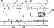
[00220]如图72至图74所示,在扳机108的初始行程的最后阶段期间,驱动通道168和带箍167相对于钳口106向着远侧方向移动,以使驱动通道168的远侧边缘接合钳口106的凸轮表面106b,使得钳口106关闭并形成位于其间的夹钳“C1”。如图74所示,推杆156的推动器156c保持在远侧位置处,在所述夹子“C”的形成期间与所述夹子“C”的后跨部接触。[00220] As shown in FIGS. 72-74, during the final stage of the initial stroke of the
[00221]如图55所示,随着扳机108被挤压最后的量,臂127继续平移通过反馈构件126的滚道126a。在这一点上,在扳机108的挤压中,手术夹子“C1”已经由钳口106完全形成。相应地,臂127将与形成于反馈构件126的滚道126a中的另一梯级126b相互作用,并产生告知用户手术夹子“C1”已由钳口106形成的听觉/触觉指示。[00221] As shown in FIG. 55,
[00222]如图75所示,手术夹子“C1”可以形成或卷曲到脉管“V”或任何其他生物组织上。[00222] As shown in FIG. 75, a surgical clip "Cl" may be formed or crimped onto a vessel "V" or any other biological tissue.
[00223]现转到图76至图84,表示随着扳机108返回至未挤压或未致动位置时的施夹器100的操作。如图76所示,随着扳机返回到未挤压位置,弹簧被允许解除压缩,从而推动曲柄板124向着近侧方向移动,而这使得柱塞向着近侧移动并向着近侧移动驱动杆。因为棘爪224已经复位,现允许曲柄板124向近侧移动直到棘爪224的齿224a再次进入曲柄板124的远侧凹槽。[00223] Turning now to FIGS. 76-84, the operation of the
[00224]如图76A所示,随着曲柄板124向着近侧移动,其臂124d脱离致动板128的指部128b,使得致动板128向着近侧方向移动。随着致动板128向着近侧移动,在其槽128b中用凸轮带动计数致动杠杆130的第二臂130b,并促使第二臂130b旋转,导致计数致动杠杆130的第一臂130a从计数机构132脱离。[00224] As shown in FIG. 76A, as crank
[00225]如图77所示,随着驱动杆140向着近侧方向移动,驱动杆140通过第一杆174b拉动连接板174。随着连接板174向着近侧方向移动,第一杆174b与第二弹簧夹子157b的尖头接合并且通过第二弹簧夹子157b向着近侧方向推动推杆156。[00225] As shown in FIG. 77, as the
[00226]如图78所示,随着力作用于推杆156上以向着近侧方向移动推杆156,所述力克服了第一弹簧夹子157a与上壳体152a的凸台152h的保持力,从而从凸台152h释放第一弹簧夹子157a并使得推杆156向着近侧方向移动。[00226] As shown in FIG. 78, as a force is applied to the
[00227]如图79所示,随着推杆156继续向着近侧方向移动,其侧凹槽156f的远端接合推进板162的翼片162b并使得推进板162向着近侧方向移动。随着推杆156向着近侧方向移动,推杆鼻部156c咬在余留的该堆夹子“C”的最远侧夹子的后方,从而变成新的最远侧夹子“C1”。[00227] As shown in FIG. 79, as the
[00228]如图80所示,随着推进板162向着近侧方向移动,夹子输出器166的近侧凸起166c接合夹子载体164的窗口164a的近侧边缘以便保持夹子输出器166在夹子载体164中的相对位置。当推进板162向着近侧方向移动,使得其远侧凸起166b从推进板162的相对近侧窗口162a到推进板162的相对远侧窗口162a向远侧推进一个窗口162a。[00228] As shown in FIG. 80, as
[00229]如图81所示,当推杆156停止其近侧移动时,当其与从上半壳体152a的内表面突出的凸台接合时,连接板174的持续的近侧移动将使得第一杆174b与第二弹簧夹子157b再次接合。随着推杆156的近侧移动停止,连接板174的持续的近侧移动将使得第一杆174b与第二弹簧夹子157b再次接合。[00229] As shown in FIG. 81, when
[00230]如图82和图83所示,随着连接板174向着近侧方向移动,由于驱动杆140的近侧移动,第二杆174c与第三弹簧夹子157c的尖头接合并通过第三弹簧夹子157c向着近侧方向推动楔形板172。随着楔形板172向着近侧方向移动,楔形板锁190向着近侧方向移动直到楔形板锁190接触下半壳体152b中的物理止挡,从而阻止楔形板172的近侧移动。一旦第三弹簧夹子157c的尖头的尖端向着远侧移动超过保护装置198,则当楔形板172停止其近侧移动时,连接板174的持续的近侧移动将使得第二杆174c与第三弹簧夹子157c再次接合。[00230] As shown in FIGS. 82 and 83, as the connecting
[00231]当扳机108返回至未致动位置时,臂127将平移通过反馈构件126的滚道126a并与形成于反馈构件126的滚道126a中的另一梯级126b相互作用,且产生告知用户手术施夹器100已被复位并准备再次发射的听觉/触觉指示。[00231] When the
[00232]现转到图84至图85,表示手术施夹器100的构造其后是最后一个手术夹子“C”的应用。如图84和图85所示,当最后一个手术夹子已经被推进和形成时,推杆156仍处于推进或远侧位置,夹子输出器166已经通过刻度盘158被逐步推进足够的量,其闭锁板165向上偏置通过推进板162的窗口162a,并进入到推杆156的远侧窗口156d中。闭锁板165在推杆156的远侧窗口156d中的定位使得近侧窗口156d的窗钩156e进入并接合闭锁板165的窗口165b。这样,因为夹子输出器166通过在夹子载体164的远侧窗口164a中接合的其远侧凸起166c来保持在远侧位置,闭锁板165接合推杆156的窗钩156e,并防止推杆156返回到最近侧位置从而使棘爪224复位。[00232] Turning now to FIGS. 84-85, the configuration of the
[00233]如图86所示,因为推杆156不能或被防止移动到其完全近侧位置,棘爪224与曲柄板124的齿条124a保持接合并且不被允许进入近侧凹槽124c从而使其本身复位。因为棘爪224不能使其本身复位,所以曲柄板124被锁住或停止向远侧或近侧移动。[00233] As shown in FIG. 86, because the
[00234]应该理解,以上描述仅仅是本公开的说明。本领域技术人员可以在不背离本公开的情况下做出各种替换和改进。相应地,本公开意在包含所有这些替换、改进和变化。参照附图所描述的实施方式仅为证明本公开的某些示例而出现。与上述的和/或所附权利要求无实质上不同的其它元件、步骤、方法和技术也在本公开的范围之内。[00234] It should be understood that the foregoing description is only illustrative of the disclosure. Various substitutions and improvements can be made by those skilled in the art without departing from the present disclosure. Accordingly, the present disclosure is intended to embrace all such alternatives, improvements and variations. The embodiments described with reference to the figures are presented merely to demonstrate some examples of the present disclosure. Other elements, steps, methods and techniques that are insubstantially different from those described above and/or appended hereto are also within the scope of the present disclosure.
Claims (24)
Translated fromChineseApplications Claiming Priority (6)
| Application Number | Priority Date | Filing Date | Title |
|---|---|---|---|
| US9279008P | 2008-08-29 | 2008-08-29 | |
| US9279408P | 2008-08-29 | 2008-08-29 | |
| US61/092,794 | 2008-08-29 | ||
| US12/539,121US8409223B2 (en) | 2008-08-29 | 2009-08-11 | Endoscopic surgical clip applier with clip retention |
| US12/539,730US8419752B2 (en) | 2008-08-29 | 2009-08-12 | Endoscopic surgical clip applier with connector plate |
| US12/539,730 | 2009-08-12 |
Related Child Applications (1)
| Application Number | Title | Priority Date | Filing Date |
|---|---|---|---|
| CN201310023275.2ADivisionCN103083059B (en) | 2008-08-29 | 2009-08-31 | Endoscopic surgical clip applier with connector plate |
Publications (2)
| Publication Number | Publication Date |
|---|---|
| CN101744648Atrue CN101744648A (en) | 2010-06-23 |
| CN101744648B CN101744648B (en) | 2013-03-13 |
Family
ID=47074461
Family Applications (4)
| Application Number | Title | Priority Date | Filing Date |
|---|---|---|---|
| CN2009101716145AActiveCN101756741B (en) | 2008-08-29 | 2009-08-31 | Endoscopic surgical clip applier |
| CN200910171615XAExpired - Fee RelatedCN101744648B (en) | 2008-08-29 | 2009-08-31 | Endoscopic surgical clip applier with connecting plate |
| CN201310049880.7AExpired - Fee RelatedCN103190939B (en) | 2008-08-29 | 2009-08-31 | There is the endoscope operation applicator of clip retention |
| CN2009101716126AExpired - Fee RelatedCN101664330B (en) | 2008-08-29 | 2009-08-31 | Endoscopic surgical clip applier with clip holder |
Family Applications Before (1)
| Application Number | Title | Priority Date | Filing Date |
|---|---|---|---|
| CN2009101716145AActiveCN101756741B (en) | 2008-08-29 | 2009-08-31 | Endoscopic surgical clip applier |
Family Applications After (2)
| Application Number | Title | Priority Date | Filing Date |
|---|---|---|---|
| CN201310049880.7AExpired - Fee RelatedCN103190939B (en) | 2008-08-29 | 2009-08-31 | There is the endoscope operation applicator of clip retention |
| CN2009101716126AExpired - Fee RelatedCN101664330B (en) | 2008-08-29 | 2009-08-31 | Endoscopic surgical clip applier with clip holder |
Country Status (8)
| Country | Link |
|---|---|
| US (10) | US8409223B2 (en) |
| EP (9) | EP2158855B1 (en) |
| JP (3) | JP5345910B2 (en) |
| CN (4) | CN101756741B (en) |
| AT (1) | ATE543445T1 (en) |
| AU (3) | AU2009210410B2 (en) |
| CA (3) | CA2675872A1 (en) |
| ES (5) | ES2378022T3 (en) |
Cited By (4)
| Publication number | Priority date | Publication date | Assignee | Title |
|---|---|---|---|---|
| CN105555207A (en)* | 2015-05-15 | 2016-05-04 | 杭州光典医疗器械有限公司 | Surgery fixture clip applier |
| CN105962985A (en)* | 2015-03-10 | 2016-09-28 | 柯惠Lp公司 | Endoscopic reposable surgical clip applier |
| CN109620357A (en)* | 2019-01-23 | 2019-04-16 | 杨美芳 | A kind of polyp of stomach injection set bundle endoscope |
| CN109952065A (en)* | 2016-11-03 | 2019-06-28 | 波士顿科学国际有限公司 | User-actuated reloadable magazine |
Families Citing this family (801)
| Publication number | Priority date | Publication date | Assignee | Title |
|---|---|---|---|---|
| EP1608272B1 (en) | 2003-03-11 | 2017-01-25 | Covidien LP | Clip applying apparatus with angled jaw |
| US9060770B2 (en) | 2003-05-20 | 2015-06-23 | Ethicon Endo-Surgery, Inc. | Robotically-driven surgical instrument with E-beam driver |
| US20070084897A1 (en) | 2003-05-20 | 2007-04-19 | Shelton Frederick E Iv | Articulating surgical stapling instrument incorporating a two-piece e-beam firing mechanism |
| US11890012B2 (en) | 2004-07-28 | 2024-02-06 | Cilag Gmbh International | Staple cartridge comprising cartridge body and attached support |
| US9072535B2 (en) | 2011-05-27 | 2015-07-07 | Ethicon Endo-Surgery, Inc. | Surgical stapling instruments with rotatable staple deployment arrangements |
| US8215531B2 (en) | 2004-07-28 | 2012-07-10 | Ethicon Endo-Surgery, Inc. | Surgical stapling instrument having a medical substance dispenser |
| US11998198B2 (en) | 2004-07-28 | 2024-06-04 | Cilag Gmbh International | Surgical stapling instrument incorporating a two-piece E-beam firing mechanism |
| CA2809110A1 (en) | 2004-10-08 | 2006-04-20 | Tyco Healthcare Group Lp | Apparatus for applying surgical clips |
| US9763668B2 (en) | 2004-10-08 | 2017-09-19 | Covidien Lp | Endoscopic surgical clip applier |
| EP2641548B1 (en) | 2004-10-08 | 2015-08-19 | Covidien LP | Endoscopic surgical clip applier |
| US7938307B2 (en) | 2004-10-18 | 2011-05-10 | Tyco Healthcare Group Lp | Support structures and methods of using the same |
| US7845536B2 (en) | 2004-10-18 | 2010-12-07 | Tyco Healthcare Group Lp | Annular adhesive structure |
| US9364229B2 (en) | 2005-03-15 | 2016-06-14 | Covidien Lp | Circular anastomosis structures |
| US10159482B2 (en) | 2005-08-31 | 2018-12-25 | Ethicon Llc | Fastener cartridge assembly comprising a fixed anvil and different staple heights |
| US7669746B2 (en) | 2005-08-31 | 2010-03-02 | Ethicon Endo-Surgery, Inc. | Staple cartridges for forming staples having differing formed staple heights |
| US7934630B2 (en) | 2005-08-31 | 2011-05-03 | Ethicon Endo-Surgery, Inc. | Staple cartridges for forming staples having differing formed staple heights |
| US7673781B2 (en) | 2005-08-31 | 2010-03-09 | Ethicon Endo-Surgery, Inc. | Surgical stapling device with staple driver that supports multiple wire diameter staples |
| US9237891B2 (en) | 2005-08-31 | 2016-01-19 | Ethicon Endo-Surgery, Inc. | Robotically-controlled surgical stapling devices that produce formed staples having different lengths |
| US11246590B2 (en) | 2005-08-31 | 2022-02-15 | Cilag Gmbh International | Staple cartridge including staple drivers having different unfired heights |
| US11484312B2 (en) | 2005-08-31 | 2022-11-01 | Cilag Gmbh International | Staple cartridge comprising a staple driver arrangement |
| US20070106317A1 (en) | 2005-11-09 | 2007-05-10 | Shelton Frederick E Iv | Hydraulically and electrically actuated articulation joints for surgical instruments |
| US11278279B2 (en) | 2006-01-31 | 2022-03-22 | Cilag Gmbh International | Surgical instrument assembly |
| US8708213B2 (en) | 2006-01-31 | 2014-04-29 | Ethicon Endo-Surgery, Inc. | Surgical instrument having a feedback system |
| US7845537B2 (en) | 2006-01-31 | 2010-12-07 | Ethicon Endo-Surgery, Inc. | Surgical instrument having recording capabilities |
| US11224427B2 (en) | 2006-01-31 | 2022-01-18 | Cilag Gmbh International | Surgical stapling system including a console and retraction assembly |
| US8820603B2 (en) | 2006-01-31 | 2014-09-02 | Ethicon Endo-Surgery, Inc. | Accessing data stored in a memory of a surgical instrument |
| US7753904B2 (en) | 2006-01-31 | 2010-07-13 | Ethicon Endo-Surgery, Inc. | Endoscopic surgical instrument with a handle that can articulate with respect to the shaft |
| US9861359B2 (en) | 2006-01-31 | 2018-01-09 | Ethicon Llc | Powered surgical instruments with firing system lockout arrangements |
| US11793518B2 (en) | 2006-01-31 | 2023-10-24 | Cilag Gmbh International | Powered surgical instruments with firing system lockout arrangements |
| US20110024477A1 (en) | 2009-02-06 | 2011-02-03 | Hall Steven G | Driven Surgical Stapler Improvements |
| US8186555B2 (en) | 2006-01-31 | 2012-05-29 | Ethicon Endo-Surgery, Inc. | Motor-driven surgical cutting and fastening instrument with mechanical closure system |
| US20110295295A1 (en) | 2006-01-31 | 2011-12-01 | Ethicon Endo-Surgery, Inc. | Robotically-controlled surgical instrument having recording capabilities |
| US20120292367A1 (en) | 2006-01-31 | 2012-11-22 | Ethicon Endo-Surgery, Inc. | Robotically-controlled end effector |
| US8992422B2 (en) | 2006-03-23 | 2015-03-31 | Ethicon Endo-Surgery, Inc. | Robotically-controlled endoscopic accessory channel |
| US8236010B2 (en) | 2006-03-23 | 2012-08-07 | Ethicon Endo-Surgery, Inc. | Surgical fastener and cutter with mimicking end effector |
| US8322455B2 (en) | 2006-06-27 | 2012-12-04 | Ethicon Endo-Surgery, Inc. | Manually driven surgical cutting and fastening instrument |
| US10568652B2 (en) | 2006-09-29 | 2020-02-25 | Ethicon Llc | Surgical staples having attached drivers of different heights and stapling instruments for deploying the same |
| US7506791B2 (en) | 2006-09-29 | 2009-03-24 | Ethicon Endo-Surgery, Inc. | Surgical stapling instrument with mechanical mechanism for limiting maximum tissue compression |
| US11980366B2 (en) | 2006-10-03 | 2024-05-14 | Cilag Gmbh International | Surgical instrument |
| CA2605135C (en) | 2006-10-17 | 2014-12-30 | Tyco Healthcare Group Lp | Apparatus for applying surgical clips |
| US8028883B2 (en) | 2006-10-26 | 2011-10-04 | Tyco Healthcare Group Lp | Methods of using shape memory alloys for buttress attachment |
| US8632535B2 (en) | 2007-01-10 | 2014-01-21 | Ethicon Endo-Surgery, Inc. | Interlock and surgical instrument including same |
| US11291441B2 (en) | 2007-01-10 | 2022-04-05 | Cilag Gmbh International | Surgical instrument with wireless communication between control unit and remote sensor |
| US8684253B2 (en) | 2007-01-10 | 2014-04-01 | Ethicon Endo-Surgery, Inc. | Surgical instrument with wireless communication between a control unit of a robotic system and remote sensor |
| US8652120B2 (en) | 2007-01-10 | 2014-02-18 | Ethicon Endo-Surgery, Inc. | Surgical instrument with wireless communication between control unit and sensor transponders |
| US20080169333A1 (en) | 2007-01-11 | 2008-07-17 | Shelton Frederick E | Surgical stapler end effector with tapered distal end |
| US11039836B2 (en) | 2007-01-11 | 2021-06-22 | Cilag Gmbh International | Staple cartridge for use with a surgical stapling instrument |
| EP3087929B1 (en) | 2007-03-06 | 2020-04-29 | Covidien LP | Surgical stapling apparatus |
| US7673782B2 (en) | 2007-03-15 | 2010-03-09 | Ethicon Endo-Surgery, Inc. | Surgical stapling instrument having a releasable buttress material |
| EP2157920B1 (en) | 2007-03-26 | 2017-09-27 | Covidien LP | Endoscopic surgical clip applier |
| US8893946B2 (en) | 2007-03-28 | 2014-11-25 | Ethicon Endo-Surgery, Inc. | Laparoscopic tissue thickness and clamp load measuring devices |
| CN102327136B (en) | 2007-04-11 | 2014-04-23 | 柯惠Lp公司 | Surgical clip applier |
| US8038045B2 (en) | 2007-05-25 | 2011-10-18 | Tyco Healthcare Group Lp | Staple buttress retention system |
| US11564682B2 (en) | 2007-06-04 | 2023-01-31 | Cilag Gmbh International | Surgical stapler device |
| US8931682B2 (en) | 2007-06-04 | 2015-01-13 | Ethicon Endo-Surgery, Inc. | Robotically-controlled shaft based rotary drive systems for surgical instruments |
| US7665646B2 (en) | 2007-06-18 | 2010-02-23 | Tyco Healthcare Group Lp | Interlocking buttress material retention system |
| US8408439B2 (en) | 2007-06-22 | 2013-04-02 | Ethicon Endo-Surgery, Inc. | Surgical stapling instrument with an articulatable end effector |
| US7753245B2 (en) | 2007-06-22 | 2010-07-13 | Ethicon Endo-Surgery, Inc. | Surgical stapling instruments |
| US8062330B2 (en) | 2007-06-27 | 2011-11-22 | Tyco Healthcare Group Lp | Buttress and surgical stapling apparatus |
| US11849941B2 (en) | 2007-06-29 | 2023-12-26 | Cilag Gmbh International | Staple cartridge having staple cavities extending at a transverse angle relative to a longitudinal cartridge axis |
| US8758391B2 (en) | 2008-02-14 | 2014-06-24 | Ethicon Endo-Surgery, Inc. | Interchangeable tools for surgical instruments |
| US8636736B2 (en) | 2008-02-14 | 2014-01-28 | Ethicon Endo-Surgery, Inc. | Motorized surgical cutting and fastening instrument |
| US7866527B2 (en) | 2008-02-14 | 2011-01-11 | Ethicon Endo-Surgery, Inc. | Surgical stapling apparatus with interlockable firing system |
| US8573465B2 (en) | 2008-02-14 | 2013-11-05 | Ethicon Endo-Surgery, Inc. | Robotically-controlled surgical end effector system with rotary actuated closure systems |
| JP5410110B2 (en) | 2008-02-14 | 2014-02-05 | エシコン・エンド−サージェリィ・インコーポレイテッド | Surgical cutting / fixing instrument with RF electrode |
| US11986183B2 (en) | 2008-02-14 | 2024-05-21 | Cilag Gmbh International | Surgical cutting and fastening instrument comprising a plurality of sensors to measure an electrical parameter |
| US8657174B2 (en) | 2008-02-14 | 2014-02-25 | Ethicon Endo-Surgery, Inc. | Motorized surgical cutting and fastening instrument having handle based power source |
| US9179912B2 (en) | 2008-02-14 | 2015-11-10 | Ethicon Endo-Surgery, Inc. | Robotically-controlled motorized surgical cutting and fastening instrument |
| US7819298B2 (en) | 2008-02-14 | 2010-10-26 | Ethicon Endo-Surgery, Inc. | Surgical stapling apparatus with control features operable with one hand |
| US9585657B2 (en) | 2008-02-15 | 2017-03-07 | Ethicon Endo-Surgery, Llc | Actuator for releasing a layer of material from a surgical end effector |
| US11272927B2 (en) | 2008-02-15 | 2022-03-15 | Cilag Gmbh International | Layer arrangements for surgical staple cartridges |
| US8465502B2 (en) | 2008-08-25 | 2013-06-18 | Covidien Lp | Surgical clip applier and method of assembly |
| US20110208212A1 (en) | 2010-02-19 | 2011-08-25 | Zergiebel Earl M | Surgical clip applier |
| JP2014208038A (en)* | 2008-08-29 | 2014-11-06 | コヴィディエン リミテッドパートナーシップ | Clip applier for endoscope surgical operation |
| US8409223B2 (en)* | 2008-08-29 | 2013-04-02 | Covidien Lp | Endoscopic surgical clip applier with clip retention |
| US9358015B2 (en) | 2008-08-29 | 2016-06-07 | Covidien Lp | Endoscopic surgical clip applier with wedge plate |
| US8267944B2 (en) | 2008-08-29 | 2012-09-18 | Tyco Healthcare Group Lp | Endoscopic surgical clip applier with lock out |
| US11648005B2 (en) | 2008-09-23 | 2023-05-16 | Cilag Gmbh International | Robotically-controlled motorized surgical instrument with an end effector |
| US9005230B2 (en) | 2008-09-23 | 2015-04-14 | Ethicon Endo-Surgery, Inc. | Motorized surgical instrument |
| US9386983B2 (en) | 2008-09-23 | 2016-07-12 | Ethicon Endo-Surgery, Llc | Robotically-controlled motorized surgical instrument |
| US8210411B2 (en) | 2008-09-23 | 2012-07-03 | Ethicon Endo-Surgery, Inc. | Motor-driven surgical cutting instrument |
| US8608045B2 (en) | 2008-10-10 | 2013-12-17 | Ethicon Endo-Sugery, Inc. | Powered surgical cutting and stapling apparatus with manually retractable firing system |
| US20100147921A1 (en) | 2008-12-16 | 2010-06-17 | Lee Olson | Surgical Apparatus Including Surgical Buttress |
| US8517239B2 (en) | 2009-02-05 | 2013-08-27 | Ethicon Endo-Surgery, Inc. | Surgical stapling instrument comprising a magnetic element driver |
| US8444036B2 (en) | 2009-02-06 | 2013-05-21 | Ethicon Endo-Surgery, Inc. | Motor driven surgical fastener device with mechanisms for adjusting a tissue gap within the end effector |
| US8453907B2 (en) | 2009-02-06 | 2013-06-04 | Ethicon Endo-Surgery, Inc. | Motor driven surgical fastener device with cutting member reversing mechanism |
| RU2525225C2 (en) | 2009-02-06 | 2014-08-10 | Этикон Эндо-Серджери, Инк. | Improvement of drive surgical suturing instrument |
| US7967179B2 (en) | 2009-03-31 | 2011-06-28 | Tyco Healthcare Group Lp | Center cinch and release of buttress material |
| US9486215B2 (en) | 2009-03-31 | 2016-11-08 | Covidien Lp | Surgical stapling apparatus |
| US8205779B2 (en)* | 2009-07-23 | 2012-06-26 | Tyco Healthcare Group Lp | Surgical stapler with tactile feedback system |
| US8734469B2 (en)* | 2009-10-13 | 2014-05-27 | Covidien Lp | Suture clip applier |
| US9610080B2 (en) | 2009-10-15 | 2017-04-04 | Covidien Lp | Staple line reinforcement for anvil and cartridge |
| US8157151B2 (en) | 2009-10-15 | 2012-04-17 | Tyco Healthcare Group Lp | Staple line reinforcement for anvil and cartridge |
| US20150231409A1 (en) | 2009-10-15 | 2015-08-20 | Covidien Lp | Buttress brachytherapy and integrated staple line markers for margin identification |
| US9693772B2 (en) | 2009-10-15 | 2017-07-04 | Covidien Lp | Staple line reinforcement for anvil and cartridge |
| US10842485B2 (en) | 2009-10-15 | 2020-11-24 | Covidien Lp | Brachytherapy buttress |
| US9186136B2 (en) | 2009-12-09 | 2015-11-17 | Covidien Lp | Surgical clip applier |
| US8545486B2 (en) | 2009-12-15 | 2013-10-01 | Covidien Lp | Surgical clip applier |
| US8851354B2 (en) | 2009-12-24 | 2014-10-07 | Ethicon Endo-Surgery, Inc. | Surgical cutting instrument that analyzes tissue thickness |
| US8220688B2 (en) | 2009-12-24 | 2012-07-17 | Ethicon Endo-Surgery, Inc. | Motor-driven surgical cutting instrument with electric actuator directional control assembly |
| US8403945B2 (en) | 2010-02-25 | 2013-03-26 | Covidien Lp | Articulating endoscopic surgical clip applier |
| WO2011112877A1 (en) | 2010-03-10 | 2011-09-15 | Menn Pavel | Surgical clips for laparoscopic procedures |
| US8968337B2 (en) | 2010-07-28 | 2015-03-03 | Covidien Lp | Articulating clip applier |
| US8403946B2 (en) | 2010-07-28 | 2013-03-26 | Covidien Lp | Articulating clip applier cartridge |
| US8783543B2 (en) | 2010-07-30 | 2014-07-22 | Ethicon Endo-Surgery, Inc. | Tissue acquisition arrangements and methods for surgical stapling devices |
| RU2013119928A (en) | 2010-09-30 | 2014-11-10 | Этикон Эндо-Серджери, Инк. | A STAPLING SYSTEM CONTAINING A RETAINING MATRIX AND A LEVELING MATRIX |
| US9016542B2 (en) | 2010-09-30 | 2015-04-28 | Ethicon Endo-Surgery, Inc. | Staple cartridge comprising compressible distortion resistant components |
| US12213666B2 (en) | 2010-09-30 | 2025-02-04 | Cilag Gmbh International | Tissue thickness compensator comprising layers |
| US9307989B2 (en) | 2012-03-28 | 2016-04-12 | Ethicon Endo-Surgery, Llc | Tissue stapler having a thickness compensator incorportating a hydrophobic agent |
| US9232941B2 (en) | 2010-09-30 | 2016-01-12 | Ethicon Endo-Surgery, Inc. | Tissue thickness compensator comprising a reservoir |
| US11298125B2 (en) | 2010-09-30 | 2022-04-12 | Cilag Gmbh International | Tissue stapler having a thickness compensator |
| US9364233B2 (en) | 2010-09-30 | 2016-06-14 | Ethicon Endo-Surgery, Llc | Tissue thickness compensators for circular surgical staplers |
| US9386988B2 (en) | 2010-09-30 | 2016-07-12 | Ethicon End-Surgery, LLC | Retainer assembly including a tissue thickness compensator |
| US9220501B2 (en) | 2010-09-30 | 2015-12-29 | Ethicon Endo-Surgery, Inc. | Tissue thickness compensators |
| US11925354B2 (en) | 2010-09-30 | 2024-03-12 | Cilag Gmbh International | Staple cartridge comprising staples positioned within a compressible portion thereof |
| US9055941B2 (en) | 2011-09-23 | 2015-06-16 | Ethicon Endo-Surgery, Inc. | Staple cartridge including collapsible deck |
| US9277919B2 (en) | 2010-09-30 | 2016-03-08 | Ethicon Endo-Surgery, Llc | Tissue thickness compensator comprising fibers to produce a resilient load |
| US9332974B2 (en) | 2010-09-30 | 2016-05-10 | Ethicon Endo-Surgery, Llc | Layered tissue thickness compensator |
| US10945731B2 (en) | 2010-09-30 | 2021-03-16 | Ethicon Llc | Tissue thickness compensator comprising controlled release and expansion |
| US11812965B2 (en) | 2010-09-30 | 2023-11-14 | Cilag Gmbh International | Layer of material for a surgical end effector |
| US9788834B2 (en) | 2010-09-30 | 2017-10-17 | Ethicon Llc | Layer comprising deployable attachment members |
| US9629814B2 (en) | 2010-09-30 | 2017-04-25 | Ethicon Endo-Surgery, Llc | Tissue thickness compensator configured to redistribute compressive forces |
| US9351730B2 (en) | 2011-04-29 | 2016-05-31 | Ethicon Endo-Surgery, Llc | Tissue thickness compensator comprising channels |
| US9314246B2 (en) | 2010-09-30 | 2016-04-19 | Ethicon Endo-Surgery, Llc | Tissue stapler having a thickness compensator incorporating an anti-inflammatory agent |
| US9301753B2 (en) | 2010-09-30 | 2016-04-05 | Ethicon Endo-Surgery, Llc | Expandable tissue thickness compensator |
| US8695866B2 (en) | 2010-10-01 | 2014-04-15 | Ethicon Endo-Surgery, Inc. | Surgical instrument having a power control circuit |
| US9011464B2 (en) | 2010-11-02 | 2015-04-21 | Covidien Lp | Self-centering clip and jaw |
| US9186153B2 (en) | 2011-01-31 | 2015-11-17 | Covidien Lp | Locking cam driver and jaw assembly for clip applier |
| US8789737B2 (en) | 2011-04-27 | 2014-07-29 | Covidien Lp | Circular stapler and staple line reinforcement material |
| US9775623B2 (en) | 2011-04-29 | 2017-10-03 | Covidien Lp | Surgical clip applier including clip relief feature |
| AU2012250197B2 (en) | 2011-04-29 | 2017-08-10 | Ethicon Endo-Surgery, Inc. | Staple cartridge comprising staples positioned within a compressible portion thereof |
| US11207064B2 (en) | 2011-05-27 | 2021-12-28 | Cilag Gmbh International | Automated end effector component reloading system for use with a robotic system |
| US20120330326A1 (en)* | 2011-06-22 | 2012-12-27 | Tyco Healthcare Group Lp | Surgical clip applier including atraumatic jaw feature |
| EP2755576B1 (en) | 2011-09-15 | 2019-05-22 | Teleflex Medical Incorporated | Automatic surgical ligation clip applier |
| EP2755578A2 (en) | 2011-09-15 | 2014-07-23 | Teleflex Medical Incorporated | Manual surgical ligation clip applier |
| US9050084B2 (en) | 2011-09-23 | 2015-06-09 | Ethicon Endo-Surgery, Inc. | Staple cartridge including collapsible deck arrangement |
| US20130131697A1 (en) | 2011-11-21 | 2013-05-23 | Covidien Lp | Surgical clip applier |
| US9351731B2 (en) | 2011-12-14 | 2016-05-31 | Covidien Lp | Surgical stapling apparatus including releasable surgical buttress |
| US9237892B2 (en) | 2011-12-14 | 2016-01-19 | Covidien Lp | Buttress attachment to the cartridge surface |
| US8967447B2 (en) | 2011-12-14 | 2015-03-03 | Covidien Lp | Surgical instrument including firing indicator |
| US9113885B2 (en) | 2011-12-14 | 2015-08-25 | Covidien Lp | Buttress assembly for use with surgical stapling device |
| US9351732B2 (en) | 2011-12-14 | 2016-05-31 | Covidien Lp | Buttress attachment to degradable polymer zones |
| US8967448B2 (en) | 2011-12-14 | 2015-03-03 | Covidien Lp | Surgical stapling apparatus including buttress attachment via tabs |
| US9364239B2 (en) | 2011-12-19 | 2016-06-14 | Covidien Lp | Jaw closure mechanism for a surgical clip applier |
| US9364216B2 (en) | 2011-12-29 | 2016-06-14 | Covidien Lp | Surgical clip applier with integrated clip counter |
| US20130172910A1 (en)* | 2011-12-29 | 2013-07-04 | Covidien Lp | Surgical clip applier |
| US8894647B2 (en)* | 2012-01-13 | 2014-11-25 | Covidien Lp | System and method for performing surgical procedures with a reusable instrument module |
| US9241757B2 (en) | 2012-01-13 | 2016-01-26 | Covidien Lp | System and method for performing surgical procedures with a reusable instrument module |
| US9636091B2 (en) | 2012-01-13 | 2017-05-02 | Covidien Lp | Hand-held electromechanical surgical system |
| US8950496B2 (en)* | 2012-01-19 | 2015-02-10 | Baker Hughes Incorporated | Counter device for selectively catching plugs |
| US9010609B2 (en) | 2012-01-26 | 2015-04-21 | Covidien Lp | Circular stapler including buttress |
| US9326773B2 (en) | 2012-01-26 | 2016-05-03 | Covidien Lp | Surgical device including buttress material |
| US9044230B2 (en) | 2012-02-13 | 2015-06-02 | Ethicon Endo-Surgery, Inc. | Surgical cutting and fastening instrument with apparatus for determining cartridge and firing motion status |
| JP6224070B2 (en) | 2012-03-28 | 2017-11-01 | エシコン・エンド−サージェリィ・インコーポレイテッドEthicon Endo−Surgery,Inc. | Retainer assembly including tissue thickness compensator |
| BR112014024098B1 (en) | 2012-03-28 | 2021-05-25 | Ethicon Endo-Surgery, Inc. | staple cartridge |
| MX358135B (en) | 2012-03-28 | 2018-08-06 | Ethicon Endo Surgery Inc | Tissue thickness compensator comprising a plurality of layers. |
| US9408610B2 (en) | 2012-05-04 | 2016-08-09 | Covidien Lp | Surgical clip applier with dissector |
| US11871901B2 (en) | 2012-05-20 | 2024-01-16 | Cilag Gmbh International | Method for situational awareness for surgical network or surgical network connected device capable of adjusting function based on a sensed situation or usage |
| US9532787B2 (en) | 2012-05-31 | 2017-01-03 | Covidien Lp | Endoscopic clip applier |
| US9101358B2 (en) | 2012-06-15 | 2015-08-11 | Ethicon Endo-Surgery, Inc. | Articulatable surgical instrument comprising a firing drive |
| US11278284B2 (en) | 2012-06-28 | 2022-03-22 | Cilag Gmbh International | Rotary drive arrangements for surgical instruments |
| JP6290201B2 (en) | 2012-06-28 | 2018-03-07 | エシコン・エンド−サージェリィ・インコーポレイテッドEthicon Endo−Surgery,Inc. | Lockout for empty clip cartridge |
| US9289256B2 (en) | 2012-06-28 | 2016-03-22 | Ethicon Endo-Surgery, Llc | Surgical end effectors having angled tissue-contacting surfaces |
| US20140005718A1 (en) | 2012-06-28 | 2014-01-02 | Ethicon Endo-Surgery, Inc. | Multi-functional powered surgical device with external dissection features |
| US20140001231A1 (en) | 2012-06-28 | 2014-01-02 | Ethicon Endo-Surgery, Inc. | Firing system lockout arrangements for surgical instruments |
| BR112014032776B1 (en) | 2012-06-28 | 2021-09-08 | Ethicon Endo-Surgery, Inc | SURGICAL INSTRUMENT SYSTEM AND SURGICAL KIT FOR USE WITH A SURGICAL INSTRUMENT SYSTEM |
| US9282974B2 (en)* | 2012-06-28 | 2016-03-15 | Ethicon Endo-Surgery, Llc | Empty clip cartridge lockout |
| US9408606B2 (en) | 2012-06-28 | 2016-08-09 | Ethicon Endo-Surgery, Llc | Robotically powered surgical device with manually-actuatable reversing system |
| US12383267B2 (en) | 2012-06-28 | 2025-08-12 | Cilag Gmbh International | Robotically powered surgical device with manually-actuatable reversing system |
| US9572576B2 (en) | 2012-07-18 | 2017-02-21 | Covidien Lp | Surgical apparatus including surgical buttress |
| US20140048580A1 (en) | 2012-08-20 | 2014-02-20 | Covidien Lp | Buttress attachment features for surgical stapling apparatus |
| US9161753B2 (en) | 2012-10-10 | 2015-10-20 | Covidien Lp | Buttress fixation for a circular stapler |
| US20140131418A1 (en) | 2012-11-09 | 2014-05-15 | Covidien Lp | Surgical Stapling Apparatus Including Buttress Attachment |
| US9295466B2 (en) | 2012-11-30 | 2016-03-29 | Covidien Lp | Surgical apparatus including surgical buttress |
| US9681936B2 (en) | 2012-11-30 | 2017-06-20 | Covidien Lp | Multi-layer porous film material |
| US9402627B2 (en) | 2012-12-13 | 2016-08-02 | Covidien Lp | Folded buttress for use with a surgical apparatus |
| US9968362B2 (en) | 2013-01-08 | 2018-05-15 | Covidien Lp | Surgical clip applier |
| US9113892B2 (en) | 2013-01-08 | 2015-08-25 | Covidien Lp | Surgical clip applier |
| US9750500B2 (en) | 2013-01-18 | 2017-09-05 | Covidien Lp | Surgical clip applier |
| US9433420B2 (en) | 2013-01-23 | 2016-09-06 | Covidien Lp | Surgical apparatus including surgical buttress |
| US9208429B2 (en) | 2013-01-31 | 2015-12-08 | Teleflex Medical Incorporated | Multiple delivery device counter and counting method |
| US9414839B2 (en) | 2013-02-04 | 2016-08-16 | Covidien Lp | Buttress attachment for circular stapling device |
| US9504470B2 (en) | 2013-02-25 | 2016-11-29 | Covidien Lp | Circular stapling device with buttress |
| US20140239047A1 (en) | 2013-02-28 | 2014-08-28 | Covidien Lp | Adherence concepts for non-woven absorbable felt buttresses |
| RU2672520C2 (en) | 2013-03-01 | 2018-11-15 | Этикон Эндо-Серджери, Инк. | Hingedly turnable surgical instruments with conducting ways for signal transfer |
| BR112015021082B1 (en) | 2013-03-01 | 2022-05-10 | Ethicon Endo-Surgery, Inc | surgical instrument |
| US9468438B2 (en) | 2013-03-01 | 2016-10-18 | Eticon Endo-Surgery, LLC | Sensor straightened end effector during removal through trocar |
| US9782173B2 (en) | 2013-03-07 | 2017-10-10 | Covidien Lp | Circular stapling device including buttress release mechanism |
| US9345481B2 (en) | 2013-03-13 | 2016-05-24 | Ethicon Endo-Surgery, Llc | Staple cartridge tissue thickness sensor system |
| US9629629B2 (en) | 2013-03-14 | 2017-04-25 | Ethicon Endo-Surgey, LLC | Control systems for surgical instruments |
| US9808244B2 (en) | 2013-03-14 | 2017-11-07 | Ethicon Llc | Sensor arrangements for absolute positioning system for surgical instruments |
| US9332984B2 (en) | 2013-03-27 | 2016-05-10 | Ethicon Endo-Surgery, Llc | Fastener cartridge assemblies |
| US9572577B2 (en) | 2013-03-27 | 2017-02-21 | Ethicon Endo-Surgery, Llc | Fastener cartridge comprising a tissue thickness compensator including openings therein |
| US9795384B2 (en) | 2013-03-27 | 2017-10-24 | Ethicon Llc | Fastener cartridge comprising a tissue thickness compensator and a gap setting element |
| BR112015026109B1 (en) | 2013-04-16 | 2022-02-22 | Ethicon Endo-Surgery, Inc | surgical instrument |
| US9826976B2 (en) | 2013-04-16 | 2017-11-28 | Ethicon Llc | Motor driven surgical instruments with lockable dual drive shafts |
| US9574644B2 (en) | 2013-05-30 | 2017-02-21 | Ethicon Endo-Surgery, Llc | Power module for use with a surgical instrument |
| US9775609B2 (en) | 2013-08-23 | 2017-10-03 | Ethicon Llc | Tamper proof circuit for surgical instrument battery pack |
| MX369362B (en) | 2013-08-23 | 2019-11-06 | Ethicon Endo Surgery Llc | Firing member retraction devices for powered surgical instruments. |
| US9775624B2 (en) | 2013-08-27 | 2017-10-03 | Covidien Lp | Surgical clip applier |
| US9655620B2 (en) | 2013-10-28 | 2017-05-23 | Covidien Lp | Circular surgical stapling device including buttress material |
| US10779838B1 (en) | 2013-11-13 | 2020-09-22 | Joseph W Blake, III | Instrument for serially applying clips to a surgical site |
| US20150173749A1 (en) | 2013-12-23 | 2015-06-25 | Ethicon Endo-Surgery, Inc. | Surgical staples and staple cartridges |
| US9839428B2 (en) | 2013-12-23 | 2017-12-12 | Ethicon Llc | Surgical cutting and stapling instruments with independent jaw control features |
| US20150173756A1 (en) | 2013-12-23 | 2015-06-25 | Ethicon Endo-Surgery, Inc. | Surgical cutting and stapling methods |
| US9724092B2 (en) | 2013-12-23 | 2017-08-08 | Ethicon Llc | Modular surgical instruments |
| US9962161B2 (en) | 2014-02-12 | 2018-05-08 | Ethicon Llc | Deliverable surgical instrument |
| US20140166724A1 (en) | 2014-02-24 | 2014-06-19 | Ethicon Endo-Surgery, Inc. | Staple cartridge including a barbed staple |
| JP6462004B2 (en) | 2014-02-24 | 2019-01-30 | エシコン エルエルシー | Fastening system with launcher lockout |
| US10117657B2 (en) | 2014-03-21 | 2018-11-06 | Arthrex, Inc. | Nautilus glenoid reamer |
| US20150272580A1 (en) | 2014-03-26 | 2015-10-01 | Ethicon Endo-Surgery, Inc. | Verification of number of battery exchanges/procedure count |
| US9913642B2 (en) | 2014-03-26 | 2018-03-13 | Ethicon Llc | Surgical instrument comprising a sensor system |
| BR112016021943B1 (en) | 2014-03-26 | 2022-06-14 | Ethicon Endo-Surgery, Llc | SURGICAL INSTRUMENT FOR USE BY AN OPERATOR IN A SURGICAL PROCEDURE |
| US12232723B2 (en) | 2014-03-26 | 2025-02-25 | Cilag Gmbh International | Systems and methods for controlling a segmented circuit |
| US10013049B2 (en) | 2014-03-26 | 2018-07-03 | Ethicon Llc | Power management through sleep options of segmented circuit and wake up control |
| US10004497B2 (en) | 2014-03-26 | 2018-06-26 | Ethicon Llc | Interface systems for use with surgical instruments |
| BR112016023825B1 (en) | 2014-04-16 | 2022-08-02 | Ethicon Endo-Surgery, Llc | STAPLE CARTRIDGE FOR USE WITH A SURGICAL STAPLER AND STAPLE CARTRIDGE FOR USE WITH A SURGICAL INSTRUMENT |
| US10470768B2 (en) | 2014-04-16 | 2019-11-12 | Ethicon Llc | Fastener cartridge including a layer attached thereto |
| US10327764B2 (en) | 2014-09-26 | 2019-06-25 | Ethicon Llc | Method for creating a flexible staple line |
| US20150297225A1 (en) | 2014-04-16 | 2015-10-22 | Ethicon Endo-Surgery, Inc. | Fastener cartridges including extensions having different configurations |
| CN106456159B (en) | 2014-04-16 | 2019-03-08 | 伊西康内外科有限责任公司 | Fastener Cartridge Assembly and Nail Retainer Cover Arrangement |
| CN106456176B (en) | 2014-04-16 | 2019-06-28 | 伊西康内外科有限责任公司 | Fastener Cartridge Including Extensions With Different Configurations |
| EP3136988B1 (en)* | 2014-04-28 | 2019-10-02 | Aesculap AG | Medical shaft-type instrument with different storage position distances due to clamp entraining elements and retaining lugs for clamps |
| US9844378B2 (en) | 2014-04-29 | 2017-12-19 | Covidien Lp | Surgical stapling apparatus and methods of adhering a surgical buttress thereto |
| US10045781B2 (en) | 2014-06-13 | 2018-08-14 | Ethicon Llc | Closure lockout systems for surgical instruments |
| US10098641B1 (en) | 2014-08-21 | 2018-10-16 | Joseph W Blake, III | Jaws and cams for clip applying instruments |
| US11311294B2 (en) | 2014-09-05 | 2022-04-26 | Cilag Gmbh International | Powered medical device including measurement of closure state of jaws |
| BR112017004361B1 (en) | 2014-09-05 | 2023-04-11 | Ethicon Llc | ELECTRONIC SYSTEM FOR A SURGICAL INSTRUMENT |
| US10135242B2 (en) | 2014-09-05 | 2018-11-20 | Ethicon Llc | Smart cartridge wake up operation and data retention |
| USD798686S1 (en)* | 2014-09-05 | 2017-10-03 | Mohammed Ali Barakat | Ergonomical trigger handle |
| US10105142B2 (en) | 2014-09-18 | 2018-10-23 | Ethicon Llc | Surgical stapler with plurality of cutting elements |
| CN107427300B (en) | 2014-09-26 | 2020-12-04 | 伊西康有限责任公司 | Surgical suture buttresses and auxiliary materials |
| US11523821B2 (en) | 2014-09-26 | 2022-12-13 | Cilag Gmbh International | Method for creating a flexible staple line |
| US10076325B2 (en) | 2014-10-13 | 2018-09-18 | Ethicon Llc | Surgical stapling apparatus comprising a tissue stop |
| US9924944B2 (en) | 2014-10-16 | 2018-03-27 | Ethicon Llc | Staple cartridge comprising an adjunct material |
| US9968363B2 (en) | 2014-10-20 | 2018-05-15 | Joseph W. Blake, III | Multi-clip applier |
| US11141153B2 (en) | 2014-10-29 | 2021-10-12 | Cilag Gmbh International | Staple cartridges comprising driver arrangements |
| US10517594B2 (en) | 2014-10-29 | 2019-12-31 | Ethicon Llc | Cartridge assemblies for surgical staplers |
| US11504192B2 (en) | 2014-10-30 | 2022-11-22 | Cilag Gmbh International | Method of hub communication with surgical instrument systems |
| US9844376B2 (en) | 2014-11-06 | 2017-12-19 | Ethicon Llc | Staple cartridge comprising a releasable adjunct material |
| US10702278B2 (en) | 2014-12-02 | 2020-07-07 | Covidien Lp | Laparoscopic surgical ligation clip applier |
| US10736636B2 (en) | 2014-12-10 | 2020-08-11 | Ethicon Llc | Articulatable surgical instrument system |
| US9943309B2 (en) | 2014-12-18 | 2018-04-17 | Ethicon Llc | Surgical instruments with articulatable end effectors and movable firing beam support arrangements |
| MX389118B (en) | 2014-12-18 | 2025-03-20 | Ethicon Llc | SURGICAL INSTRUMENT WITH AN ANVIL THAT CAN BE SELECTIVELY MOVED ON A DISCRETE, NON-MOBILE AXIS RELATIVE TO A STAPLE CARTRIDGE. |
| US10188385B2 (en) | 2014-12-18 | 2019-01-29 | Ethicon Llc | Surgical instrument system comprising lockable systems |
| US9844375B2 (en) | 2014-12-18 | 2017-12-19 | Ethicon Llc | Drive arrangements for articulatable surgical instruments |
| US10085748B2 (en) | 2014-12-18 | 2018-10-02 | Ethicon Llc | Locking arrangements for detachable shaft assemblies with articulatable surgical end effectors |
| US10117649B2 (en) | 2014-12-18 | 2018-11-06 | Ethicon Llc | Surgical instrument assembly comprising a lockable articulation system |
| US9987000B2 (en) | 2014-12-18 | 2018-06-05 | Ethicon Llc | Surgical instrument assembly comprising a flexible articulation system |
| US9844374B2 (en) | 2014-12-18 | 2017-12-19 | Ethicon Llc | Surgical instrument systems comprising an articulatable end effector and means for adjusting the firing stroke of a firing member |
| CN107548295B (en)* | 2014-12-30 | 2020-06-09 | 瑟吉玛蒂克斯公司 | Laparoscopic suturing device with impulse deployment |
| US9931124B2 (en) | 2015-01-07 | 2018-04-03 | Covidien Lp | Reposable clip applier |
| CN107205747B (en) | 2015-01-15 | 2020-09-08 | 柯惠有限合伙公司 | Reusable endoscopic surgical clip applier |
| US10292712B2 (en) | 2015-01-28 | 2019-05-21 | Covidien Lp | Surgical clip applier with integrated cutter |
| US10180463B2 (en) | 2015-02-27 | 2019-01-15 | Ethicon Llc | Surgical apparatus configured to assess whether a performance parameter of the surgical apparatus is within an acceptable performance band |
| US9993258B2 (en) | 2015-02-27 | 2018-06-12 | Ethicon Llc | Adaptable surgical instrument handle |
| US11154301B2 (en) | 2015-02-27 | 2021-10-26 | Cilag Gmbh International | Modular stapling assembly |
| US10159483B2 (en) | 2015-02-27 | 2018-12-25 | Ethicon Llc | Surgical apparatus configured to track an end-of-life parameter |
| US9901342B2 (en) | 2015-03-06 | 2018-02-27 | Ethicon Endo-Surgery, Llc | Signal and power communication system positioned on a rotatable shaft |
| US10441279B2 (en) | 2015-03-06 | 2019-10-15 | Ethicon Llc | Multiple level thresholds to modify operation of powered surgical instruments |
| US9993248B2 (en) | 2015-03-06 | 2018-06-12 | Ethicon Endo-Surgery, Llc | Smart sensors with local signal processing |
| US9808246B2 (en) | 2015-03-06 | 2017-11-07 | Ethicon Endo-Surgery, Llc | Method of operating a powered surgical instrument |
| US10548504B2 (en) | 2015-03-06 | 2020-02-04 | Ethicon Llc | Overlaid multi sensor radio frequency (RF) electrode system to measure tissue compression |
| US9895148B2 (en) | 2015-03-06 | 2018-02-20 | Ethicon Endo-Surgery, Llc | Monitoring speed control and precision incrementing of motor for powered surgical instruments |
| US10617412B2 (en) | 2015-03-06 | 2020-04-14 | Ethicon Llc | System for detecting the mis-insertion of a staple cartridge into a surgical stapler |
| US10687806B2 (en) | 2015-03-06 | 2020-06-23 | Ethicon Llc | Adaptive tissue compression techniques to adjust closure rates for multiple tissue types |
| US10245033B2 (en) | 2015-03-06 | 2019-04-02 | Ethicon Llc | Surgical instrument comprising a lockable battery housing |
| US10045776B2 (en) | 2015-03-06 | 2018-08-14 | Ethicon Llc | Control techniques and sub-processor contained within modular shaft with select control processing from handle |
| JP2020121162A (en) | 2015-03-06 | 2020-08-13 | エシコン エルエルシーEthicon LLC | Time dependent evaluation of sensor data to determine stability element, creep element and viscoelastic element of measurement |
| US9924961B2 (en) | 2015-03-06 | 2018-03-27 | Ethicon Endo-Surgery, Llc | Interactive feedback system for powered surgical instruments |
| US10433844B2 (en) | 2015-03-31 | 2019-10-08 | Ethicon Llc | Surgical instrument with selectively disengageable threaded drive systems |
| US11020578B2 (en) | 2015-04-10 | 2021-06-01 | Covidien Lp | Surgical stapler with integrated bladder |
| CN106137303B (en)* | 2015-04-23 | 2018-09-25 | 北京派尔特医疗科技股份有限公司 | A kind of titanium clamp pincers |
| US10251662B2 (en)* | 2015-06-04 | 2019-04-09 | Covidien Lp | Surgical instruments for blunt and sharp tissue dissection |
| WO2016192096A1 (en)* | 2015-06-05 | 2016-12-08 | Covidien Lp | Endoscopic reposable surgical clip applier |
| US10154841B2 (en) | 2015-06-18 | 2018-12-18 | Ethicon Llc | Surgical stapling instruments with lockout arrangements for preventing firing system actuation when a cartridge is spent or missing |
| US10835249B2 (en) | 2015-08-17 | 2020-11-17 | Ethicon Llc | Implantable layers for a surgical instrument |
| MX2018002392A (en) | 2015-08-26 | 2018-08-01 | Ethicon Llc | Staple cartridge assembly comprising various tissue compression gaps and staple forming gaps. |
| US10980538B2 (en) | 2015-08-26 | 2021-04-20 | Ethicon Llc | Surgical stapling configurations for curved and circular stapling instruments |
| RU2725081C2 (en) | 2015-08-26 | 2020-06-29 | ЭТИКОН ЭлЭлСи | Strips with surgical staples allowing the presence of staples with variable properties and providing simple loading of the cartridge |
| MX2022009705A (en) | 2015-08-26 | 2022-11-07 | Ethicon Llc | Surgical staples comprising hardness variations for improved fastening of tissue. |
| MX2022006189A (en) | 2015-09-02 | 2022-06-16 | Ethicon Llc | Surgical staple configurations with camming surfaces located between portions supporting surgical staples. |
| US10238390B2 (en) | 2015-09-02 | 2019-03-26 | Ethicon Llc | Surgical staple cartridges with driver arrangements for establishing herringbone staple patterns |
| US10085751B2 (en) | 2015-09-23 | 2018-10-02 | Ethicon Llc | Surgical stapler having temperature-based motor control |
| US10076326B2 (en) | 2015-09-23 | 2018-09-18 | Ethicon Llc | Surgical stapler having current mirror-based motor control |
| US10105139B2 (en) | 2015-09-23 | 2018-10-23 | Ethicon Llc | Surgical stapler having downstream current-based motor control |
| US10363036B2 (en) | 2015-09-23 | 2019-07-30 | Ethicon Llc | Surgical stapler having force-based motor control |
| US10327769B2 (en) | 2015-09-23 | 2019-06-25 | Ethicon Llc | Surgical stapler having motor control based on a drive system component |
| US10238386B2 (en) | 2015-09-23 | 2019-03-26 | Ethicon Llc | Surgical stapler having motor control based on an electrical parameter related to a motor current |
| US10299878B2 (en) | 2015-09-25 | 2019-05-28 | Ethicon Llc | Implantable adjunct systems for determining adjunct skew |
| US10478188B2 (en) | 2015-09-30 | 2019-11-19 | Ethicon Llc | Implantable layer comprising a constricted configuration |
| US11890015B2 (en) | 2015-09-30 | 2024-02-06 | Cilag Gmbh International | Compressible adjunct with crossing spacer fibers |
| US10433846B2 (en) | 2015-09-30 | 2019-10-08 | Ethicon Llc | Compressible adjunct with crossing spacer fibers |
| US10980539B2 (en) | 2015-09-30 | 2021-04-20 | Ethicon Llc | Implantable adjunct comprising bonded layers |
| US10660652B2 (en) | 2015-10-10 | 2020-05-26 | Covidien Lp | Endoscopic surgical clip applier |
| CN108348259B (en)* | 2015-11-03 | 2020-12-11 | 柯惠有限合伙公司 | Endoscopic Surgical Fixture Applicator |
| US10905425B2 (en) | 2015-11-10 | 2021-02-02 | Covidien Lp | Endoscopic reposable surgical clip applier |
| US10390831B2 (en) | 2015-11-10 | 2019-08-27 | Covidien Lp | Endoscopic reposable surgical clip applier |
| US10702280B2 (en) | 2015-11-10 | 2020-07-07 | Covidien Lp | Endoscopic reposable surgical clip applier |
| WO2017079970A1 (en)* | 2015-11-13 | 2017-05-18 | Covidien Lp | Circular stapler with audible indicator mechanism |
| US10952726B2 (en) | 2015-12-10 | 2021-03-23 | Covidien Lp | Handheld electromechanical surgical instruments |
| US10292704B2 (en) | 2015-12-30 | 2019-05-21 | Ethicon Llc | Mechanisms for compensating for battery pack failure in powered surgical instruments |
| US10265068B2 (en) | 2015-12-30 | 2019-04-23 | Ethicon Llc | Surgical instruments with separable motors and motor control circuits |
| US10368865B2 (en) | 2015-12-30 | 2019-08-06 | Ethicon Llc | Mechanisms for compensating for drivetrain failure in powered surgical instruments |
| CN108472044B (en) | 2016-01-11 | 2021-04-16 | 柯惠有限合伙公司 | endoscope-reserved surgical clip applier |
| GB201600546D0 (en)* | 2016-01-12 | 2016-02-24 | Gyrus Medical Ltd | Electrosurgical device |
| AU2016388454A1 (en) | 2016-01-18 | 2018-07-19 | Covidien Lp | Endoscopic surgical clip applier |
| US10413291B2 (en) | 2016-02-09 | 2019-09-17 | Ethicon Llc | Surgical instrument articulation mechanism with slotted secondary constraint |
| US11213293B2 (en) | 2016-02-09 | 2022-01-04 | Cilag Gmbh International | Articulatable surgical instruments with single articulation link arrangements |
| BR112018016098B1 (en) | 2016-02-09 | 2023-02-23 | Ethicon Llc | SURGICAL INSTRUMENT |
| US10448948B2 (en) | 2016-02-12 | 2019-10-22 | Ethicon Llc | Mechanisms for compensating for drivetrain failure in powered surgical instruments |
| US11224426B2 (en) | 2016-02-12 | 2022-01-18 | Cilag Gmbh International | Mechanisms for compensating for drivetrain failure in powered surgical instruments |
| US10258331B2 (en) | 2016-02-12 | 2019-04-16 | Ethicon Llc | Mechanisms for compensating for drivetrain failure in powered surgical instruments |
| CA2958160A1 (en) | 2016-02-24 | 2017-08-24 | Covidien Lp | Endoscopic reposable surgical clip applier |
| US10413297B2 (en) | 2016-04-01 | 2019-09-17 | Ethicon Llc | Surgical stapling system configured to apply annular rows of staples having different heights |
| US10617413B2 (en) | 2016-04-01 | 2020-04-14 | Ethicon Llc | Closure system arrangements for surgical cutting and stapling devices with separate and distinct firing shafts |
| US11179150B2 (en) | 2016-04-15 | 2021-11-23 | Cilag Gmbh International | Systems and methods for controlling a surgical stapling and cutting instrument |
| US10828028B2 (en) | 2016-04-15 | 2020-11-10 | Ethicon Llc | Surgical instrument with multiple program responses during a firing motion |
| US10456137B2 (en) | 2016-04-15 | 2019-10-29 | Ethicon Llc | Staple formation detection mechanisms |
| US10405859B2 (en) | 2016-04-15 | 2019-09-10 | Ethicon Llc | Surgical instrument with adjustable stop/start control during a firing motion |
| US10492783B2 (en) | 2016-04-15 | 2019-12-03 | Ethicon, Llc | Surgical instrument with improved stop/start control during a firing motion |
| US10335145B2 (en) | 2016-04-15 | 2019-07-02 | Ethicon Llc | Modular surgical instrument with configurable operating mode |
| US10357247B2 (en) | 2016-04-15 | 2019-07-23 | Ethicon Llc | Surgical instrument with multiple program responses during a firing motion |
| US11607239B2 (en) | 2016-04-15 | 2023-03-21 | Cilag Gmbh International | Systems and methods for controlling a surgical stapling and cutting instrument |
| US10426467B2 (en) | 2016-04-15 | 2019-10-01 | Ethicon Llc | Surgical instrument with detection sensors |
| US11317917B2 (en) | 2016-04-18 | 2022-05-03 | Cilag Gmbh International | Surgical stapling system comprising a lockable firing assembly |
| US20170296173A1 (en) | 2016-04-18 | 2017-10-19 | Ethicon Endo-Surgery, Llc | Method for operating a surgical instrument |
| US10363037B2 (en) | 2016-04-18 | 2019-07-30 | Ethicon Llc | Surgical instrument system comprising a magnetic lockout |
| WO2017184964A1 (en) | 2016-04-21 | 2017-10-26 | Applied Medical Resources Corporation | Laparoscopic clip applier |
| US10959731B2 (en) | 2016-06-14 | 2021-03-30 | Covidien Lp | Buttress attachment for surgical stapling instrument |
| JP6980705B2 (en) | 2016-06-24 | 2021-12-15 | エシコン エルエルシーEthicon LLC | Stapling system for use with wire staples and punched staples |
| USD850617S1 (en) | 2016-06-24 | 2019-06-04 | Ethicon Llc | Surgical fastener cartridge |
| JP6957532B2 (en) | 2016-06-24 | 2021-11-02 | エシコン エルエルシーEthicon LLC | Staple cartridges including wire staples and punched staples |
| US10893863B2 (en) | 2016-06-24 | 2021-01-19 | Ethicon Llc | Staple cartridge comprising offset longitudinal staple rows |
| USD826405S1 (en) | 2016-06-24 | 2018-08-21 | Ethicon Llc | Surgical fastener |
| USD847989S1 (en) | 2016-06-24 | 2019-05-07 | Ethicon Llc | Surgical fastener cartridge |
| US20180008277A1 (en)* | 2016-07-11 | 2018-01-11 | Covidien Lp | Endoscopic reposable surgical clip applier |
| WO2018027788A1 (en) | 2016-08-11 | 2018-02-15 | Covidien Lp | Endoscopic surgical clip applier and clip applying systems |
| US10500000B2 (en) | 2016-08-16 | 2019-12-10 | Ethicon Llc | Surgical tool with manual control of end effector jaws |
| CN109640844B (en)* | 2016-08-25 | 2021-08-06 | 柯惠Lp公司 | Endoscopic Surgical Clip Appliers and Applicator Systems |
| US10639044B2 (en) | 2016-10-31 | 2020-05-05 | Covidien Lp | Ligation clip module and clip applier |
| US10660651B2 (en) | 2016-10-31 | 2020-05-26 | Covidien Lp | Endoscopic reposable surgical clip applier |
| US10492795B2 (en) | 2016-11-01 | 2019-12-03 | Covidien Lp | Endoscopic surgical clip applier |
| US10426489B2 (en) | 2016-11-01 | 2019-10-01 | Covidien Lp | Endoscopic reposable surgical clip applier |
| US10610236B2 (en) | 2016-11-01 | 2020-04-07 | Covidien Lp | Endoscopic reposable surgical clip applier |
| US11026686B2 (en) | 2016-11-08 | 2021-06-08 | Covidien Lp | Structure for attaching buttress to anvil and/or cartridge of surgical stapling instrument |
| TWI627933B (en)* | 2016-11-10 | 2018-07-01 | 亞培高利控股有限公司 | Clip pusher structure of clip applier |
| US10542982B2 (en) | 2016-12-21 | 2020-01-28 | Ethicon Llc | Shaft assembly comprising first and second articulation lockouts |
| US10695055B2 (en) | 2016-12-21 | 2020-06-30 | Ethicon Llc | Firing assembly comprising a lockout |
| US10993715B2 (en) | 2016-12-21 | 2021-05-04 | Ethicon Llc | Staple cartridge comprising staples with different clamping breadths |
| JP7010957B2 (en) | 2016-12-21 | 2022-01-26 | エシコン エルエルシー | Shaft assembly with lockout |
| US10980536B2 (en) | 2016-12-21 | 2021-04-20 | Ethicon Llc | No-cartridge and spent cartridge lockout arrangements for surgical staplers |
| US10568625B2 (en) | 2016-12-21 | 2020-02-25 | Ethicon Llc | Staple cartridges and arrangements of staples and staple cavities therein |
| US10945727B2 (en) | 2016-12-21 | 2021-03-16 | Ethicon Llc | Staple cartridge with deformable driver retention features |
| CN110087565A (en) | 2016-12-21 | 2019-08-02 | 爱惜康有限责任公司 | Surgical stapling system |
| US20180168648A1 (en) | 2016-12-21 | 2018-06-21 | Ethicon Endo-Surgery, Llc | Durability features for end effectors and firing assemblies of surgical stapling instruments |
| US10758229B2 (en) | 2016-12-21 | 2020-09-01 | Ethicon Llc | Surgical instrument comprising improved jaw control |
| US20180168615A1 (en) | 2016-12-21 | 2018-06-21 | Ethicon Endo-Surgery, Llc | Method of deforming staples from two different types of staple cartridges with the same surgical stapling instrument |
| US11419606B2 (en) | 2016-12-21 | 2022-08-23 | Cilag Gmbh International | Shaft assembly comprising a clutch configured to adapt the output of a rotary firing member to two different systems |
| US20180168625A1 (en) | 2016-12-21 | 2018-06-21 | Ethicon Endo-Surgery, Llc | Surgical stapling instruments with smart staple cartridges |
| US11134942B2 (en) | 2016-12-21 | 2021-10-05 | Cilag Gmbh International | Surgical stapling instruments and staple-forming anvils |
| US10426471B2 (en) | 2016-12-21 | 2019-10-01 | Ethicon Llc | Surgical instrument with multiple failure response modes |
| US10898186B2 (en) | 2016-12-21 | 2021-01-26 | Ethicon Llc | Staple forming pocket arrangements comprising primary sidewalls and pocket sidewalls |
| US10485543B2 (en) | 2016-12-21 | 2019-11-26 | Ethicon Llc | Anvil having a knife slot width |
| US11684367B2 (en) | 2016-12-21 | 2023-06-27 | Cilag Gmbh International | Stepped assembly having and end-of-life indicator |
| US10582928B2 (en) | 2016-12-21 | 2020-03-10 | Ethicon Llc | Articulation lock arrangements for locking an end effector in an articulated position in response to actuation of a jaw closure system |
| US10973516B2 (en) | 2016-12-21 | 2021-04-13 | Ethicon Llc | Surgical end effectors and adaptable firing members therefor |
| US11090048B2 (en) | 2016-12-21 | 2021-08-17 | Cilag Gmbh International | Method for resetting a fuse of a surgical instrument shaft |
| JP7010956B2 (en) | 2016-12-21 | 2022-01-26 | エシコン エルエルシー | How to staple tissue |
| US10687810B2 (en) | 2016-12-21 | 2020-06-23 | Ethicon Llc | Stepped staple cartridge with tissue retention and gap setting features |
| JP2020501815A (en) | 2016-12-21 | 2020-01-23 | エシコン エルエルシーEthicon LLC | Surgical stapling system |
| JP6983893B2 (en) | 2016-12-21 | 2021-12-17 | エシコン エルエルシーEthicon LLC | Lockout configuration for surgical end effectors and replaceable tool assemblies |
| US10813638B2 (en) | 2016-12-21 | 2020-10-27 | Ethicon Llc | Surgical end effectors with expandable tissue stop arrangements |
| MX2019007295A (en) | 2016-12-21 | 2019-10-15 | Ethicon Llc | Surgical instrument system comprising an end effector lockout and a firing assembly lockout. |
| US10807147B2 (en)* | 2017-01-06 | 2020-10-20 | Korvis Asia Private Limited | Platform for constraining a workpiece on an x-y stage |
| US10874768B2 (en) | 2017-01-20 | 2020-12-29 | Covidien Lp | Drug eluting medical device |
| US10709455B2 (en) | 2017-02-02 | 2020-07-14 | Covidien Lp | Endoscopic surgical clip applier |
| US11116514B2 (en) | 2017-02-06 | 2021-09-14 | Covidien Lp | Surgical clip applier with user feedback feature |
| US10758244B2 (en) | 2017-02-06 | 2020-09-01 | Covidien Lp | Endoscopic surgical clip applier |
| US10660725B2 (en) | 2017-02-14 | 2020-05-26 | Covidien Lp | Endoscopic surgical clip applier including counter assembly |
| US10603038B2 (en) | 2017-02-22 | 2020-03-31 | Covidien Lp | Surgical clip applier including inserts for jaw assembly |
| US10548602B2 (en) | 2017-02-23 | 2020-02-04 | Covidien Lp | Endoscopic surgical clip applier |
| US11583291B2 (en) | 2017-02-23 | 2023-02-21 | Covidien Lp | Endoscopic surgical clip applier |
| US10925607B2 (en) | 2017-02-28 | 2021-02-23 | Covidien Lp | Surgical stapling apparatus with staple sheath |
| US10368868B2 (en) | 2017-03-09 | 2019-08-06 | Covidien Lp | Structure for attaching buttress material to anvil and cartridge of surgical stapling instrument |
| US11096610B2 (en) | 2017-03-28 | 2021-08-24 | Covidien Lp | Surgical implants including sensing fibers |
| US10675043B2 (en) | 2017-05-04 | 2020-06-09 | Covidien Lp | Reposable multi-fire surgical clip applier |
| US10722235B2 (en) | 2017-05-11 | 2020-07-28 | Covidien Lp | Spring-release surgical clip |
| USD879809S1 (en) | 2017-06-20 | 2020-03-31 | Ethicon Llc | Display panel with changeable graphical user interface |
| US11653914B2 (en) | 2017-06-20 | 2023-05-23 | Cilag Gmbh International | Systems and methods for controlling motor velocity of a surgical stapling and cutting instrument according to articulation angle of end effector |
| US10368864B2 (en) | 2017-06-20 | 2019-08-06 | Ethicon Llc | Systems and methods for controlling displaying motor velocity for a surgical instrument |
| US10624633B2 (en) | 2017-06-20 | 2020-04-21 | Ethicon Llc | Systems and methods for controlling motor velocity of a surgical stapling and cutting instrument |
| US10881399B2 (en) | 2017-06-20 | 2021-01-05 | Ethicon Llc | Techniques for adaptive control of motor velocity of a surgical stapling and cutting instrument |
| US11090046B2 (en) | 2017-06-20 | 2021-08-17 | Cilag Gmbh International | Systems and methods for controlling displacement member motion of a surgical stapling and cutting instrument |
| US10307170B2 (en) | 2017-06-20 | 2019-06-04 | Ethicon Llc | Method for closed loop control of motor velocity of a surgical stapling and cutting instrument |
| US10779820B2 (en) | 2017-06-20 | 2020-09-22 | Ethicon Llc | Systems and methods for controlling motor speed according to user input for a surgical instrument |
| US10813639B2 (en) | 2017-06-20 | 2020-10-27 | Ethicon Llc | Closed loop feedback control of motor velocity of a surgical stapling and cutting instrument based on system conditions |
| US11382638B2 (en) | 2017-06-20 | 2022-07-12 | Cilag Gmbh International | Closed loop feedback control of motor velocity of a surgical stapling and cutting instrument based on measured time over a specified displacement distance |
| US10646220B2 (en) | 2017-06-20 | 2020-05-12 | Ethicon Llc | Systems and methods for controlling displacement member velocity for a surgical instrument |
| US11071554B2 (en) | 2017-06-20 | 2021-07-27 | Cilag Gmbh International | Closed loop feedback control of motor velocity of a surgical stapling and cutting instrument based on magnitude of velocity error measurements |
| US11517325B2 (en) | 2017-06-20 | 2022-12-06 | Cilag Gmbh International | Closed loop feedback control of motor velocity of a surgical stapling and cutting instrument based on measured displacement distance traveled over a specified time interval |
| US10327767B2 (en) | 2017-06-20 | 2019-06-25 | Ethicon Llc | Control of motor velocity of a surgical stapling and cutting instrument based on angle of articulation |
| US10390841B2 (en) | 2017-06-20 | 2019-08-27 | Ethicon Llc | Control of motor velocity of a surgical stapling and cutting instrument based on angle of articulation |
| US10888321B2 (en) | 2017-06-20 | 2021-01-12 | Ethicon Llc | Systems and methods for controlling velocity of a displacement member of a surgical stapling and cutting instrument |
| US10980537B2 (en) | 2017-06-20 | 2021-04-20 | Ethicon Llc | Closed loop feedback control of motor velocity of a surgical stapling and cutting instrument based on measured time over a specified number of shaft rotations |
| US10881396B2 (en) | 2017-06-20 | 2021-01-05 | Ethicon Llc | Surgical instrument with variable duration trigger arrangement |
| USD879808S1 (en) | 2017-06-20 | 2020-03-31 | Ethicon Llc | Display panel with graphical user interface |
| USD890784S1 (en) | 2017-06-20 | 2020-07-21 | Ethicon Llc | Display panel with changeable graphical user interface |
| CN110769765B (en)* | 2017-06-21 | 2022-12-30 | 富士胶片株式会社 | Clamp treatment tool |
| US11090049B2 (en) | 2017-06-27 | 2021-08-17 | Cilag Gmbh International | Staple forming pocket arrangements |
| US10856869B2 (en) | 2017-06-27 | 2020-12-08 | Ethicon Llc | Surgical anvil arrangements |
| US10772629B2 (en) | 2017-06-27 | 2020-09-15 | Ethicon Llc | Surgical anvil arrangements |
| US10993716B2 (en) | 2017-06-27 | 2021-05-04 | Ethicon Llc | Surgical anvil arrangements |
| US11324503B2 (en) | 2017-06-27 | 2022-05-10 | Cilag Gmbh International | Surgical firing member arrangements |
| US11266405B2 (en) | 2017-06-27 | 2022-03-08 | Cilag Gmbh International | Surgical anvil manufacturing methods |
| US11259805B2 (en) | 2017-06-28 | 2022-03-01 | Cilag Gmbh International | Surgical instrument comprising firing member supports |
| US11484310B2 (en) | 2017-06-28 | 2022-11-01 | Cilag Gmbh International | Surgical instrument comprising a shaft including a closure tube profile |
| USD869655S1 (en) | 2017-06-28 | 2019-12-10 | Ethicon Llc | Surgical fastener cartridge |
| EP3420947B1 (en) | 2017-06-28 | 2022-05-25 | Cilag GmbH International | Surgical instrument comprising selectively actuatable rotatable couplers |
| US11564686B2 (en) | 2017-06-28 | 2023-01-31 | Cilag Gmbh International | Surgical shaft assemblies with flexible interfaces |
| CN110799119B (en)* | 2017-06-28 | 2023-04-18 | 爱惜康有限责任公司 | Surgical instrument with axially movable closure member |
| US10903685B2 (en) | 2017-06-28 | 2021-01-26 | Ethicon Llc | Surgical shaft assemblies with slip ring assemblies forming capacitive channels |
| USD851762S1 (en) | 2017-06-28 | 2019-06-18 | Ethicon Llc | Anvil |
| USD906355S1 (en) | 2017-06-28 | 2020-12-29 | Ethicon Llc | Display screen or portion thereof with a graphical user interface for a surgical instrument |
| US11246592B2 (en) | 2017-06-28 | 2022-02-15 | Cilag Gmbh International | Surgical instrument comprising an articulation system lockable to a frame |
| US10716614B2 (en) | 2017-06-28 | 2020-07-21 | Ethicon Llc | Surgical shaft assemblies with slip ring assemblies with increased contact pressure |
| USD854151S1 (en) | 2017-06-28 | 2019-07-16 | Ethicon Llc | Surgical instrument shaft |
| US10758232B2 (en) | 2017-06-28 | 2020-09-01 | Ethicon Llc | Surgical instrument with positive jaw opening features |
| US10211586B2 (en) | 2017-06-28 | 2019-02-19 | Ethicon Llc | Surgical shaft assemblies with watertight housings |
| US10765427B2 (en) | 2017-06-28 | 2020-09-08 | Ethicon Llc | Method for articulating a surgical instrument |
| US10932772B2 (en) | 2017-06-29 | 2021-03-02 | Ethicon Llc | Methods for closed loop velocity control for robotic surgical instrument |
| US10398434B2 (en) | 2017-06-29 | 2019-09-03 | Ethicon Llc | Closed loop velocity control of closure member for robotic surgical instrument |
| US11007022B2 (en) | 2017-06-29 | 2021-05-18 | Ethicon Llc | Closed loop velocity control techniques based on sensed tissue parameters for robotic surgical instrument |
| US10898183B2 (en) | 2017-06-29 | 2021-01-26 | Ethicon Llc | Robotic surgical instrument with closed loop feedback techniques for advancement of closure member during firing |
| US10258418B2 (en) | 2017-06-29 | 2019-04-16 | Ethicon Llc | System for controlling articulation forces |
| US10660723B2 (en) | 2017-06-30 | 2020-05-26 | Covidien Lp | Endoscopic reposable surgical clip applier |
| US10639032B2 (en) | 2017-06-30 | 2020-05-05 | Covidien Lp | Endoscopic surgical clip applier including counter assembly |
| US11944300B2 (en) | 2017-08-03 | 2024-04-02 | Cilag Gmbh International | Method for operating a surgical system bailout |
| US11471155B2 (en) | 2017-08-03 | 2022-10-18 | Cilag Gmbh International | Surgical system bailout |
| US11974742B2 (en) | 2017-08-03 | 2024-05-07 | Cilag Gmbh International | Surgical system comprising an articulation bailout |
| US11304695B2 (en) | 2017-08-03 | 2022-04-19 | Cilag Gmbh International | Surgical system shaft interconnection |
| US10849625B2 (en) | 2017-08-07 | 2020-12-01 | Covidien Lp | Surgical buttress retention systems for surgical stapling apparatus |
| US10675112B2 (en) | 2017-08-07 | 2020-06-09 | Covidien Lp | Endoscopic surgical clip applier including counter assembly |
| US10863992B2 (en)* | 2017-08-08 | 2020-12-15 | Covidien Lp | Endoscopic surgical clip applier |
| US10932790B2 (en) | 2017-08-08 | 2021-03-02 | Covidien Lp | Geared actuation mechanism and surgical clip applier including the same |
| US10786262B2 (en) | 2017-08-09 | 2020-09-29 | Covidien Lp | Endoscopic reposable surgical clip applier |
| US10786263B2 (en) | 2017-08-15 | 2020-09-29 | Covidien Lp | Endoscopic reposable surgical clip applier |
| TWI645831B (en)* | 2017-08-18 | 2019-01-01 | 台灣先進手術醫療器材股份有限公司 | Blood clip applier |
| US10945733B2 (en) | 2017-08-23 | 2021-03-16 | Covidien Lp | Surgical buttress reload and tip attachment assemblies for surgical stapling apparatus |
| US10835341B2 (en) | 2017-09-12 | 2020-11-17 | Covidien Lp | Endoscopic surgical clip applier and handle assemblies for use therewith |
| US10835260B2 (en) | 2017-09-13 | 2020-11-17 | Covidien Lp | Endoscopic surgical clip applier and handle assemblies for use therewith |
| US10758245B2 (en) | 2017-09-13 | 2020-09-01 | Covidien Lp | Clip counting mechanism for surgical clip applier |
| US10653429B2 (en) | 2017-09-13 | 2020-05-19 | Covidien Lp | Endoscopic surgical clip applier |
| USD907648S1 (en) | 2017-09-29 | 2021-01-12 | Ethicon Llc | Display screen or portion thereof with animated graphical user interface |
| US11399829B2 (en) | 2017-09-29 | 2022-08-02 | Cilag Gmbh International | Systems and methods of initiating a power shutdown mode for a surgical instrument |
| USD917500S1 (en) | 2017-09-29 | 2021-04-27 | Ethicon Llc | Display screen or portion thereof with graphical user interface |
| US10729501B2 (en) | 2017-09-29 | 2020-08-04 | Ethicon Llc | Systems and methods for language selection of a surgical instrument |
| US10743872B2 (en) | 2017-09-29 | 2020-08-18 | Ethicon Llc | System and methods for controlling a display of a surgical instrument |
| US10765429B2 (en) | 2017-09-29 | 2020-09-08 | Ethicon Llc | Systems and methods for providing alerts according to the operational state of a surgical instrument |
| USD907647S1 (en) | 2017-09-29 | 2021-01-12 | Ethicon Llc | Display screen or portion thereof with animated graphical user interface |
| US10796471B2 (en) | 2017-09-29 | 2020-10-06 | Ethicon Llc | Systems and methods of displaying a knife position for a surgical instrument |
| US11564756B2 (en) | 2017-10-30 | 2023-01-31 | Cilag Gmbh International | Method of hub communication with surgical instrument systems |
| US11510741B2 (en) | 2017-10-30 | 2022-11-29 | Cilag Gmbh International | Method for producing a surgical instrument comprising a smart electrical system |
| US11026687B2 (en)* | 2017-10-30 | 2021-06-08 | Cilag Gmbh International | Clip applier comprising clip advancing systems |
| US11925373B2 (en) | 2017-10-30 | 2024-03-12 | Cilag Gmbh International | Surgical suturing instrument comprising a non-circular needle |
| US11317919B2 (en)* | 2017-10-30 | 2022-05-03 | Cilag Gmbh International | Clip applier comprising a clip crimping system |
| US11090075B2 (en) | 2017-10-30 | 2021-08-17 | Cilag Gmbh International | Articulation features for surgical end effector |
| US11801098B2 (en) | 2017-10-30 | 2023-10-31 | Cilag Gmbh International | Method of hub communication with surgical instrument systems |
| US11311342B2 (en) | 2017-10-30 | 2022-04-26 | Cilag Gmbh International | Method for communicating with surgical instrument systems |
| US11291510B2 (en) | 2017-10-30 | 2022-04-05 | Cilag Gmbh International | Method of hub communication with surgical instrument systems |
| US11911045B2 (en) | 2017-10-30 | 2024-02-27 | Cllag GmbH International | Method for operating a powered articulating multi-clip applier |
| US11134944B2 (en) | 2017-10-30 | 2021-10-05 | Cilag Gmbh International | Surgical stapler knife motion controls |
| US10779903B2 (en) | 2017-10-31 | 2020-09-22 | Ethicon Llc | Positive shaft rotation lock activated by jaw closure |
| US10842490B2 (en) | 2017-10-31 | 2020-11-24 | Ethicon Llc | Cartridge body design with force reduction based on firing completion |
| US10945734B2 (en) | 2017-11-03 | 2021-03-16 | Covidien Lp | Rotation knob assemblies and surgical instruments including the same |
| US11116513B2 (en) | 2017-11-03 | 2021-09-14 | Covidien Lp | Modular surgical clip cartridge |
| US10828036B2 (en) | 2017-11-03 | 2020-11-10 | Covidien Lp | Endoscopic surgical clip applier and handle assemblies for use therewith |
| US11376015B2 (en) | 2017-11-03 | 2022-07-05 | Covidien Lp | Endoscopic surgical clip applier and handle assemblies for use therewith |
| US10932791B2 (en) | 2017-11-03 | 2021-03-02 | Covidien Lp | Reposable multi-fire surgical clip applier |
| US11141151B2 (en) | 2017-12-08 | 2021-10-12 | Covidien Lp | Surgical buttress for circular stapling |
| US10722236B2 (en) | 2017-12-12 | 2020-07-28 | Covidien Lp | Endoscopic reposable surgical clip applier |
| US10849630B2 (en) | 2017-12-13 | 2020-12-01 | Covidien Lp | Reposable multi-fire surgical clip applier |
| US10743887B2 (en) | 2017-12-13 | 2020-08-18 | Covidien Lp | Reposable multi-fire surgical clip applier |
| US10959737B2 (en) | 2017-12-13 | 2021-03-30 | Covidien Lp | Reposable multi-fire surgical clip applier |
| US10779825B2 (en) | 2017-12-15 | 2020-09-22 | Ethicon Llc | Adapters with end effector position sensing and control arrangements for use in connection with electromechanical surgical instruments |
| US10743875B2 (en) | 2017-12-15 | 2020-08-18 | Ethicon Llc | Surgical end effectors with jaw stiffener arrangements configured to permit monitoring of firing member |
| US10966718B2 (en) | 2017-12-15 | 2021-04-06 | Ethicon Llc | Dynamic clamping assemblies with improved wear characteristics for use in connection with electromechanical surgical instruments |
| US10779826B2 (en) | 2017-12-15 | 2020-09-22 | Ethicon Llc | Methods of operating surgical end effectors |
| US10687813B2 (en) | 2017-12-15 | 2020-06-23 | Ethicon Llc | Adapters with firing stroke sensing arrangements for use in connection with electromechanical surgical instruments |
| US11071543B2 (en) | 2017-12-15 | 2021-07-27 | Cilag Gmbh International | Surgical end effectors with clamping assemblies configured to increase jaw aperture ranges |
| US10869666B2 (en) | 2017-12-15 | 2020-12-22 | Ethicon Llc | Adapters with control systems for controlling multiple motors of an electromechanical surgical instrument |
| US10828033B2 (en) | 2017-12-15 | 2020-11-10 | Ethicon Llc | Handheld electromechanical surgical instruments with improved motor control arrangements for positioning components of an adapter coupled thereto |
| US11197670B2 (en) | 2017-12-15 | 2021-12-14 | Cilag Gmbh International | Surgical end effectors with pivotal jaws configured to touch at their respective distal ends when fully closed |
| US11006955B2 (en) | 2017-12-15 | 2021-05-18 | Ethicon Llc | End effectors with positive jaw opening features for use with adapters for electromechanical surgical instruments |
| US10743874B2 (en) | 2017-12-15 | 2020-08-18 | Ethicon Llc | Sealed adapters for use with electromechanical surgical instruments |
| US11033267B2 (en) | 2017-12-15 | 2021-06-15 | Ethicon Llc | Systems and methods of controlling a clamping member firing rate of a surgical instrument |
| US11020112B2 (en) | 2017-12-19 | 2021-06-01 | Ethicon Llc | Surgical tools configured for interchangeable use with different controller interfaces |
| US11045270B2 (en) | 2017-12-19 | 2021-06-29 | Cilag Gmbh International | Robotic attachment comprising exterior drive actuator |
| US10729509B2 (en) | 2017-12-19 | 2020-08-04 | Ethicon Llc | Surgical instrument comprising closure and firing locking mechanism |
| US10835330B2 (en) | 2017-12-19 | 2020-11-17 | Ethicon Llc | Method for determining the position of a rotatable jaw of a surgical instrument attachment assembly |
| US10716565B2 (en) | 2017-12-19 | 2020-07-21 | Ethicon Llc | Surgical instruments with dual articulation drivers |
| USD910847S1 (en) | 2017-12-19 | 2021-02-16 | Ethicon Llc | Surgical instrument assembly |
| US12336705B2 (en) | 2017-12-21 | 2025-06-24 | Cilag Gmbh International | Continuous use self-propelled stapling instrument |
| US11076853B2 (en) | 2017-12-21 | 2021-08-03 | Cilag Gmbh International | Systems and methods of displaying a knife position during transection for a surgical instrument |
| US11311290B2 (en) | 2017-12-21 | 2022-04-26 | Cilag Gmbh International | Surgical instrument comprising an end effector dampener |
| US11179151B2 (en) | 2017-12-21 | 2021-11-23 | Cilag Gmbh International | Surgical instrument comprising a display |
| US11129680B2 (en) | 2017-12-21 | 2021-09-28 | Cilag Gmbh International | Surgical instrument comprising a projector |
| US12096916B2 (en) | 2017-12-28 | 2024-09-24 | Cilag Gmbh International | Method of sensing particulate from smoke evacuated from a patient, adjusting the pump speed based on the sensed information, and communicating the functional parameters of the system to the hub |
| US11253315B2 (en) | 2017-12-28 | 2022-02-22 | Cilag Gmbh International | Increasing radio frequency to create pad-less monopolar loop |
| US11419667B2 (en) | 2017-12-28 | 2022-08-23 | Cilag Gmbh International | Ultrasonic energy device which varies pressure applied by clamp arm to provide threshold control pressure at a cut progression location |
| US11076921B2 (en) | 2017-12-28 | 2021-08-03 | Cilag Gmbh International | Adaptive control program updates for surgical hubs |
| US12062442B2 (en) | 2017-12-28 | 2024-08-13 | Cilag Gmbh International | Method for operating surgical instrument systems |
| US11132462B2 (en) | 2017-12-28 | 2021-09-28 | Cilag Gmbh International | Data stripping method to interrogate patient records and create anonymized record |
| US11896443B2 (en) | 2017-12-28 | 2024-02-13 | Cilag Gmbh International | Control of a surgical system through a surgical barrier |
| US11896322B2 (en) | 2017-12-28 | 2024-02-13 | Cilag Gmbh International | Sensing the patient position and contact utilizing the mono-polar return pad electrode to provide situational awareness to the hub |
| US11376002B2 (en) | 2017-12-28 | 2022-07-05 | Cilag Gmbh International | Surgical instrument cartridge sensor assemblies |
| US11423007B2 (en) | 2017-12-28 | 2022-08-23 | Cilag Gmbh International | Adjustment of device control programs based on stratified contextual data in addition to the data |
| US12376855B2 (en) | 2017-12-28 | 2025-08-05 | Cilag Gmbh International | Safety systems for smart powered surgical stapling |
| US11864728B2 (en) | 2017-12-28 | 2024-01-09 | Cilag Gmbh International | Characterization of tissue irregularities through the use of mono-chromatic light refractivity |
| US11419630B2 (en) | 2017-12-28 | 2022-08-23 | Cilag Gmbh International | Surgical system distributed processing |
| US11696760B2 (en) | 2017-12-28 | 2023-07-11 | Cilag Gmbh International | Safety systems for smart powered surgical stapling |
| US11666331B2 (en) | 2017-12-28 | 2023-06-06 | Cilag Gmbh International | Systems for detecting proximity of surgical end effector to cancerous tissue |
| US11589888B2 (en) | 2017-12-28 | 2023-02-28 | Cilag Gmbh International | Method for controlling smart energy devices |
| US20190201112A1 (en) | 2017-12-28 | 2019-07-04 | Ethicon Llc | Computer implemented interactive surgical systems |
| US11464535B2 (en) | 2017-12-28 | 2022-10-11 | Cilag Gmbh International | Detection of end effector emersion in liquid |
| US11857152B2 (en) | 2017-12-28 | 2024-01-02 | Cilag Gmbh International | Surgical hub spatial awareness to determine devices in operating theater |
| US11832840B2 (en) | 2017-12-28 | 2023-12-05 | Cilag Gmbh International | Surgical instrument having a flexible circuit |
| US11317937B2 (en) | 2018-03-08 | 2022-05-03 | Cilag Gmbh International | Determining the state of an ultrasonic end effector |
| US11659023B2 (en) | 2017-12-28 | 2023-05-23 | Cilag Gmbh International | Method of hub communication |
| US12396806B2 (en) | 2017-12-28 | 2025-08-26 | Cilag Gmbh International | Adjustment of a surgical device function based on situational awareness |
| US11744604B2 (en) | 2017-12-28 | 2023-09-05 | Cilag Gmbh International | Surgical instrument with a hardware-only control circuit |
| US11678881B2 (en) | 2017-12-28 | 2023-06-20 | Cilag Gmbh International | Spatial awareness of surgical hubs in operating rooms |
| US11266468B2 (en) | 2017-12-28 | 2022-03-08 | Cilag Gmbh International | Cooperative utilization of data derived from secondary sources by intelligent surgical hubs |
| US20190201039A1 (en) | 2017-12-28 | 2019-07-04 | Ethicon Llc | Situational awareness of electrosurgical systems |
| US11166772B2 (en) | 2017-12-28 | 2021-11-09 | Cilag Gmbh International | Surgical hub coordination of control and communication of operating room devices |
| US11308075B2 (en) | 2017-12-28 | 2022-04-19 | Cilag Gmbh International | Surgical network, instrument, and cloud responses based on validation of received dataset and authentication of its source and integrity |
| US11832899B2 (en) | 2017-12-28 | 2023-12-05 | Cilag Gmbh International | Surgical systems with autonomously adjustable control programs |
| US11969216B2 (en) | 2017-12-28 | 2024-04-30 | Cilag Gmbh International | Surgical network recommendations from real time analysis of procedure variables against a baseline highlighting differences from the optimal solution |
| US10892995B2 (en) | 2017-12-28 | 2021-01-12 | Ethicon Llc | Surgical network determination of prioritization of communication, interaction, or processing based on system or device needs |
| US11410259B2 (en) | 2017-12-28 | 2022-08-09 | Cilag Gmbh International | Adaptive control program updates for surgical devices |
| US11602393B2 (en) | 2017-12-28 | 2023-03-14 | Cilag Gmbh International | Surgical evacuation sensing and generator control |
| US11389164B2 (en) | 2017-12-28 | 2022-07-19 | Cilag Gmbh International | Method of using reinforced flexible circuits with multiple sensors to optimize performance of radio frequency devices |
| US11559308B2 (en) | 2017-12-28 | 2023-01-24 | Cilag Gmbh International | Method for smart energy device infrastructure |
| WO2019133144A1 (en) | 2017-12-28 | 2019-07-04 | Ethicon Llc | Detection and escalation of security responses of surgical instruments to increasing severity threats |
| US11529187B2 (en) | 2017-12-28 | 2022-12-20 | Cilag Gmbh International | Surgical evacuation sensor arrangements |
| US11903601B2 (en) | 2017-12-28 | 2024-02-20 | Cilag Gmbh International | Surgical instrument comprising a plurality of drive systems |
| US11179175B2 (en) | 2017-12-28 | 2021-11-23 | Cilag Gmbh International | Controlling an ultrasonic surgical instrument according to tissue location |
| US20190206569A1 (en) | 2017-12-28 | 2019-07-04 | Ethicon Llc | Method of cloud based data analytics for use with the hub |
| US11364075B2 (en) | 2017-12-28 | 2022-06-21 | Cilag Gmbh International | Radio frequency energy device for delivering combined electrical signals |
| US11540855B2 (en) | 2017-12-28 | 2023-01-03 | Cilag Gmbh International | Controlling activation of an ultrasonic surgical instrument according to the presence of tissue |
| US11311306B2 (en) | 2017-12-28 | 2022-04-26 | Cilag Gmbh International | Surgical systems for detecting end effector tissue distribution irregularities |
| US11464559B2 (en) | 2017-12-28 | 2022-10-11 | Cilag Gmbh International | Estimating state of ultrasonic end effector and control system therefor |
| US11576677B2 (en) | 2017-12-28 | 2023-02-14 | Cilag Gmbh International | Method of hub communication, processing, display, and cloud analytics |
| US11432885B2 (en) | 2017-12-28 | 2022-09-06 | Cilag Gmbh International | Sensing arrangements for robot-assisted surgical platforms |
| US11278281B2 (en) | 2017-12-28 | 2022-03-22 | Cilag Gmbh International | Interactive surgical system |
| US11424027B2 (en) | 2017-12-28 | 2022-08-23 | Cilag Gmbh International | Method for operating surgical instrument systems |
| US11612444B2 (en) | 2017-12-28 | 2023-03-28 | Cilag Gmbh International | Adjustment of a surgical device function based on situational awareness |
| US11818052B2 (en) | 2017-12-28 | 2023-11-14 | Cilag Gmbh International | Surgical network determination of prioritization of communication, interaction, or processing based on system or device needs |
| US11937769B2 (en) | 2017-12-28 | 2024-03-26 | Cilag Gmbh International | Method of hub communication, processing, storage and display |
| US10918310B2 (en) | 2018-01-03 | 2021-02-16 | Biosense Webster (Israel) Ltd. | Fast anatomical mapping (FAM) using volume filling |
| US11633237B2 (en) | 2017-12-28 | 2023-04-25 | Cilag Gmbh International | Usage and technique analysis of surgeon / staff performance against a baseline to optimize device utilization and performance for both current and future procedures |
| US11013563B2 (en) | 2017-12-28 | 2021-05-25 | Ethicon Llc | Drive arrangements for robot-assisted surgical platforms |
| US11786251B2 (en) | 2017-12-28 | 2023-10-17 | Cilag Gmbh International | Method for adaptive control schemes for surgical network control and interaction |
| US11291495B2 (en) | 2017-12-28 | 2022-04-05 | Cilag Gmbh International | Interruption of energy due to inadvertent capacitive coupling |
| US11324557B2 (en) | 2017-12-28 | 2022-05-10 | Cilag Gmbh International | Surgical instrument with a sensing array |
| US11998193B2 (en) | 2017-12-28 | 2024-06-04 | Cilag Gmbh International | Method for usage of the shroud as an aspect of sensing or controlling a powered surgical device, and a control algorithm to adjust its default operation |
| US11571234B2 (en) | 2017-12-28 | 2023-02-07 | Cilag Gmbh International | Temperature control of ultrasonic end effector and control system therefor |
| US11559307B2 (en) | 2017-12-28 | 2023-01-24 | Cilag Gmbh International | Method of robotic hub communication, detection, and control |
| US11969142B2 (en) | 2017-12-28 | 2024-04-30 | Cilag Gmbh International | Method of compressing tissue within a stapling device and simultaneously displaying the location of the tissue within the jaws |
| US10758310B2 (en) | 2017-12-28 | 2020-09-01 | Ethicon Llc | Wireless pairing of a surgical device with another device within a sterile surgical field based on the usage and situational awareness of devices |
| US11202570B2 (en) | 2017-12-28 | 2021-12-21 | Cilag Gmbh International | Communication hub and storage device for storing parameters and status of a surgical device to be shared with cloud based analytics systems |
| US11304745B2 (en) | 2017-12-28 | 2022-04-19 | Cilag Gmbh International | Surgical evacuation sensing and display |
| US11026751B2 (en) | 2017-12-28 | 2021-06-08 | Cilag Gmbh International | Display of alignment of staple cartridge to prior linear staple line |
| US11304699B2 (en) | 2017-12-28 | 2022-04-19 | Cilag Gmbh International | Method for adaptive control schemes for surgical network control and interaction |
| US12127729B2 (en) | 2017-12-28 | 2024-10-29 | Cilag Gmbh International | Method for smoke evacuation for surgical hub |
| US20190201142A1 (en) | 2017-12-28 | 2019-07-04 | Ethicon Llc | Automatic tool adjustments for robot-assisted surgical platforms |
| US11786245B2 (en) | 2017-12-28 | 2023-10-17 | Cilag Gmbh International | Surgical systems with prioritized data transmission capabilities |
| US11304763B2 (en) | 2017-12-28 | 2022-04-19 | Cilag Gmbh International | Image capturing of the areas outside the abdomen to improve placement and control of a surgical device in use |
| US11446052B2 (en) | 2017-12-28 | 2022-09-20 | Cilag Gmbh International | Variation of radio frequency and ultrasonic power level in cooperation with varying clamp arm pressure to achieve predefined heat flux or power applied to tissue |
| US11257589B2 (en) | 2017-12-28 | 2022-02-22 | Cilag Gmbh International | Real-time analysis of comprehensive cost of all instrumentation used in surgery utilizing data fluidity to track instruments through stocking and in-house processes |
| US11304720B2 (en) | 2017-12-28 | 2022-04-19 | Cilag Gmbh International | Activation of energy devices |
| US11109866B2 (en) | 2017-12-28 | 2021-09-07 | Cilag Gmbh International | Method for circular stapler control algorithm adjustment based on situational awareness |
| US20190201090A1 (en) | 2017-12-28 | 2019-07-04 | Ethicon Llc | Capacitive coupled return path pad with separable array elements |
| US20210059681A1 (en)* | 2018-01-09 | 2021-03-04 | Covidien Lp | Reposable multi-fire surgical clip applier |
| US11051827B2 (en)* | 2018-01-16 | 2021-07-06 | Covidien Lp | Endoscopic surgical instrument and handle assemblies for use therewith |
| US11065000B2 (en) | 2018-02-22 | 2021-07-20 | Covidien Lp | Surgical buttresses for surgical stapling apparatus |
| US12303159B2 (en) | 2018-03-08 | 2025-05-20 | Cilag Gmbh International | Methods for estimating and controlling state of ultrasonic end effector |
| US11534196B2 (en) | 2018-03-08 | 2022-12-27 | Cilag Gmbh International | Using spectroscopy to determine device use state in combo instrument |
| US11986233B2 (en) | 2018-03-08 | 2024-05-21 | Cilag Gmbh International | Adjustment of complex impedance to compensate for lost power in an articulating ultrasonic device |
| US11259830B2 (en) | 2018-03-08 | 2022-03-01 | Cilag Gmbh International | Methods for controlling temperature in ultrasonic device |
| US11213294B2 (en) | 2018-03-28 | 2022-01-04 | Cilag Gmbh International | Surgical instrument comprising co-operating lockout features |
| US11589865B2 (en) | 2018-03-28 | 2023-02-28 | Cilag Gmbh International | Methods for controlling a powered surgical stapler that has separate rotary closure and firing systems |
| US11278280B2 (en) | 2018-03-28 | 2022-03-22 | Cilag Gmbh International | Surgical instrument comprising a jaw closure lockout |
| US11471156B2 (en) | 2018-03-28 | 2022-10-18 | Cilag Gmbh International | Surgical stapling devices with improved rotary driven closure systems |
| US11090047B2 (en) | 2018-03-28 | 2021-08-17 | Cilag Gmbh International | Surgical instrument comprising an adaptive control system |
| US10993721B2 (en) | 2018-04-25 | 2021-05-04 | Covidien Lp | Surgical clip applier |
| US10758237B2 (en) | 2018-04-30 | 2020-09-01 | Covidien Lp | Circular stapling apparatus with pinned buttress |
| US11284896B2 (en) | 2018-05-09 | 2022-03-29 | Covidien Lp | Surgical buttress loading and attaching/detaching assemblies |
| US11432818B2 (en) | 2018-05-09 | 2022-09-06 | Covidien Lp | Surgical buttress assemblies |
| US11426163B2 (en) | 2018-05-09 | 2022-08-30 | Covidien Lp | Universal linear surgical stapling buttress |
| US11219460B2 (en) | 2018-07-02 | 2022-01-11 | Covidien Lp | Surgical stapling apparatus with anvil buttress |
| US10786273B2 (en) | 2018-07-13 | 2020-09-29 | Covidien Lp | Rotation knob assemblies for handle assemblies |
| US11259887B2 (en) | 2018-08-10 | 2022-03-01 | Covidien Lp | Feedback mechanisms for handle assemblies |
| US11219463B2 (en) | 2018-08-13 | 2022-01-11 | Covidien Lp | Bilateral spring for surgical instruments and surgical instruments including the same |
| US11033256B2 (en) | 2018-08-13 | 2021-06-15 | Covidien Lp | Linkage assembly for reusable surgical handle assemblies |
| US11253267B2 (en) | 2018-08-13 | 2022-02-22 | Covidien Lp | Friction reduction mechanisms for handle assemblies |
| US11278267B2 (en) | 2018-08-13 | 2022-03-22 | Covidien Lp | Latch assemblies and surgical instruments including the same |
| US11246601B2 (en) | 2018-08-13 | 2022-02-15 | Covidien Lp | Elongated assemblies for surgical clip appliers and surgical clip appliers incorporating the same |
| US11344316B2 (en) | 2018-08-13 | 2022-05-31 | Covidien Lp | Elongated assemblies for surgical clip appliers and surgical clip appliers incorporating the same |
| US11051828B2 (en) | 2018-08-13 | 2021-07-06 | Covidien Lp | Rotation knob assemblies and surgical instruments including same |
| US10856870B2 (en) | 2018-08-20 | 2020-12-08 | Ethicon Llc | Switching arrangements for motor powered articulatable surgical instruments |
| US11207065B2 (en) | 2018-08-20 | 2021-12-28 | Cilag Gmbh International | Method for fabricating surgical stapler anvils |
| US11324501B2 (en) | 2018-08-20 | 2022-05-10 | Cilag Gmbh International | Surgical stapling devices with improved closure members |
| US20200054321A1 (en) | 2018-08-20 | 2020-02-20 | Ethicon Llc | Surgical instruments with progressive jaw closure arrangements |
| US11045192B2 (en) | 2018-08-20 | 2021-06-29 | Cilag Gmbh International | Fabricating techniques for surgical stapler anvils |
| US10842492B2 (en) | 2018-08-20 | 2020-11-24 | Ethicon Llc | Powered articulatable surgical instruments with clutching and locking arrangements for linking an articulation drive system to a firing drive system |
| US10912559B2 (en) | 2018-08-20 | 2021-02-09 | Ethicon Llc | Reinforced deformable anvil tip for surgical stapler anvil |
| US11291440B2 (en) | 2018-08-20 | 2022-04-05 | Cilag Gmbh International | Method for operating a powered articulatable surgical instrument |
| US11253256B2 (en) | 2018-08-20 | 2022-02-22 | Cilag Gmbh International | Articulatable motor powered surgical instruments with dedicated articulation motor arrangements |
| US11083458B2 (en) | 2018-08-20 | 2021-08-10 | Cilag Gmbh International | Powered surgical instruments with clutching arrangements to convert linear drive motions to rotary drive motions |
| US11039834B2 (en) | 2018-08-20 | 2021-06-22 | Cilag Gmbh International | Surgical stapler anvils with staple directing protrusions and tissue stability features |
| US10779821B2 (en) | 2018-08-20 | 2020-09-22 | Ethicon Llc | Surgical stapler anvils with tissue stop features configured to avoid tissue pinch |
| USD914878S1 (en) | 2018-08-20 | 2021-03-30 | Ethicon Llc | Surgical instrument anvil |
| US10806459B2 (en) | 2018-09-14 | 2020-10-20 | Covidien Lp | Drug patterned reinforcement material for circular anastomosis |
| TWI679001B (en)* | 2018-09-14 | 2019-12-11 | 台灣先進手術醫療器材股份有限公司 | Clip assembly for surgical clip |
| US11147566B2 (en) | 2018-10-01 | 2021-10-19 | Covidien Lp | Endoscopic surgical clip applier |
| US10952729B2 (en) | 2018-10-03 | 2021-03-23 | Covidien Lp | Universal linear buttress retention/release assemblies and methods |
| USD904611S1 (en) | 2018-10-10 | 2020-12-08 | Bolder Surgical, Llc | Jaw design for a surgical instrument |
| US11369377B2 (en) | 2019-02-19 | 2022-06-28 | Cilag Gmbh International | Surgical stapling assembly with cartridge based retainer configured to unlock a firing lockout |
| US11464511B2 (en) | 2019-02-19 | 2022-10-11 | Cilag Gmbh International | Surgical staple cartridges with movable authentication key arrangements |
| US11317915B2 (en) | 2019-02-19 | 2022-05-03 | Cilag Gmbh International | Universal cartridge based key feature that unlocks multiple lockout arrangements in different surgical staplers |
| US11331100B2 (en) | 2019-02-19 | 2022-05-17 | Cilag Gmbh International | Staple cartridge retainer system with authentication keys |
| US11357503B2 (en) | 2019-02-19 | 2022-06-14 | Cilag Gmbh International | Staple cartridge retainers with frangible retention features and methods of using same |
| TWI690295B (en)* | 2019-03-15 | 2020-04-11 | 台灣先進手術醫療器材股份有限公司 | Surgical clip applier with automatic unhooking function |
| US11524398B2 (en) | 2019-03-19 | 2022-12-13 | Covidien Lp | Gear drive mechanisms for surgical instruments |
| US11147551B2 (en) | 2019-03-25 | 2021-10-19 | Cilag Gmbh International | Firing drive arrangements for surgical systems |
| US11147553B2 (en) | 2019-03-25 | 2021-10-19 | Cilag Gmbh International | Firing drive arrangements for surgical systems |
| US11172929B2 (en) | 2019-03-25 | 2021-11-16 | Cilag Gmbh International | Articulation drive arrangements for surgical systems |
| US11696761B2 (en) | 2019-03-25 | 2023-07-11 | Cilag Gmbh International | Firing drive arrangements for surgical systems |
| US11730472B2 (en) | 2019-04-25 | 2023-08-22 | Covidien Lp | Surgical system and surgical loading units thereof |
| US11426251B2 (en) | 2019-04-30 | 2022-08-30 | Cilag Gmbh International | Articulation directional lights on a surgical instrument |
| US11253254B2 (en) | 2019-04-30 | 2022-02-22 | Cilag Gmbh International | Shaft rotation actuator on a surgical instrument |
| US11432816B2 (en) | 2019-04-30 | 2022-09-06 | Cilag Gmbh International | Articulation pin for a surgical instrument |
| US11452528B2 (en) | 2019-04-30 | 2022-09-27 | Cilag Gmbh International | Articulation actuators for a surgical instrument |
| US11648009B2 (en) | 2019-04-30 | 2023-05-16 | Cilag Gmbh International | Rotatable jaw tip for a surgical instrument |
| US11903581B2 (en) | 2019-04-30 | 2024-02-20 | Cilag Gmbh International | Methods for stapling tissue using a surgical instrument |
| US11471157B2 (en) | 2019-04-30 | 2022-10-18 | Cilag Gmbh International | Articulation control mapping for a surgical instrument |
| US11596403B2 (en) | 2019-05-08 | 2023-03-07 | Covidien Lp | Surgical stapling device |
| US11478245B2 (en) | 2019-05-08 | 2022-10-25 | Covidien Lp | Surgical stapling device |
| USD952144S1 (en) | 2019-06-25 | 2022-05-17 | Cilag Gmbh International | Surgical staple cartridge retainer with firing system authentication key |
| USD950728S1 (en) | 2019-06-25 | 2022-05-03 | Cilag Gmbh International | Surgical staple cartridge |
| USD964564S1 (en) | 2019-06-25 | 2022-09-20 | Cilag Gmbh International | Surgical staple cartridge retainer with a closure system authentication key |
| US11523822B2 (en) | 2019-06-28 | 2022-12-13 | Cilag Gmbh International | Battery pack including a circuit interrupter |
| US11684434B2 (en) | 2019-06-28 | 2023-06-27 | Cilag Gmbh International | Surgical RFID assemblies for instrument operational setting control |
| US11298132B2 (en) | 2019-06-28 | 2022-04-12 | Cilag GmbH Inlernational | Staple cartridge including a honeycomb extension |
| US11660163B2 (en) | 2019-06-28 | 2023-05-30 | Cilag Gmbh International | Surgical system with RFID tags for updating motor assembly parameters |
| US11298127B2 (en) | 2019-06-28 | 2022-04-12 | Cilag GmbH Interational | Surgical stapling system having a lockout mechanism for an incompatible cartridge |
| US11051807B2 (en) | 2019-06-28 | 2021-07-06 | Cilag Gmbh International | Packaging assembly including a particulate trap |
| US11771419B2 (en) | 2019-06-28 | 2023-10-03 | Cilag Gmbh International | Packaging for a replaceable component of a surgical stapling system |
| US11399837B2 (en) | 2019-06-28 | 2022-08-02 | Cilag Gmbh International | Mechanisms for motor control adjustments of a motorized surgical instrument |
| US11497492B2 (en) | 2019-06-28 | 2022-11-15 | Cilag Gmbh International | Surgical instrument including an articulation lock |
| US11241235B2 (en) | 2019-06-28 | 2022-02-08 | Cilag Gmbh International | Method of using multiple RFID chips with a surgical assembly |
| US11638587B2 (en) | 2019-06-28 | 2023-05-02 | Cilag Gmbh International | RFID identification systems for surgical instruments |
| US11478241B2 (en) | 2019-06-28 | 2022-10-25 | Cilag Gmbh International | Staple cartridge including projections |
| US12004740B2 (en) | 2019-06-28 | 2024-06-11 | Cilag Gmbh International | Surgical stapling system having an information decryption protocol |
| US11426167B2 (en) | 2019-06-28 | 2022-08-30 | Cilag Gmbh International | Mechanisms for proper anvil attachment surgical stapling head assembly |
| US11553971B2 (en) | 2019-06-28 | 2023-01-17 | Cilag Gmbh International | Surgical RFID assemblies for display and communication |
| US11224497B2 (en) | 2019-06-28 | 2022-01-18 | Cilag Gmbh International | Surgical systems with multiple RFID tags |
| US11291451B2 (en) | 2019-06-28 | 2022-04-05 | Cilag Gmbh International | Surgical instrument with battery compatibility verification functionality |
| US11464601B2 (en) | 2019-06-28 | 2022-10-11 | Cilag Gmbh International | Surgical instrument comprising an RFID system for tracking a movable component |
| US11259803B2 (en) | 2019-06-28 | 2022-03-01 | Cilag Gmbh International | Surgical stapling system having an information encryption protocol |
| US11246678B2 (en) | 2019-06-28 | 2022-02-15 | Cilag Gmbh International | Surgical stapling system having a frangible RFID tag |
| US11376098B2 (en) | 2019-06-28 | 2022-07-05 | Cilag Gmbh International | Surgical instrument system comprising an RFID system |
| US11627959B2 (en) | 2019-06-28 | 2023-04-18 | Cilag Gmbh International | Surgical instruments including manual and powered system lockouts |
| US11219455B2 (en) | 2019-06-28 | 2022-01-11 | Cilag Gmbh International | Surgical instrument including a lockout key |
| US11969169B2 (en) | 2019-09-10 | 2024-04-30 | Covidien Lp | Anvil buttress loading unit for a surgical stapling apparatus |
| US11571208B2 (en) | 2019-10-11 | 2023-02-07 | Covidien Lp | Surgical buttress loading units |
| CN112690864B (en)* | 2019-10-23 | 2022-03-22 | 苏州英途康医疗科技有限公司 | Medical instrument and automatic clamp feeding method |
| CN112690861B (en)* | 2019-10-23 | 2023-01-20 | 苏州英途康医疗科技有限公司 | Medical instrument, working head and clip feeding position identification method |
| US11523824B2 (en) | 2019-12-12 | 2022-12-13 | Covidien Lp | Anvil buttress loading for a surgical stapling apparatus |
| US11701111B2 (en) | 2019-12-19 | 2023-07-18 | Cilag Gmbh International | Method for operating a surgical stapling instrument |
| US11559304B2 (en) | 2019-12-19 | 2023-01-24 | Cilag Gmbh International | Surgical instrument comprising a rapid closure mechanism |
| US11844520B2 (en) | 2019-12-19 | 2023-12-19 | Cilag Gmbh International | Staple cartridge comprising driver retention members |
| US11931033B2 (en) | 2019-12-19 | 2024-03-19 | Cilag Gmbh International | Staple cartridge comprising a latch lockout |
| US11446029B2 (en) | 2019-12-19 | 2022-09-20 | Cilag Gmbh International | Staple cartridge comprising projections extending from a curved deck surface |
| US11607219B2 (en) | 2019-12-19 | 2023-03-21 | Cilag Gmbh International | Staple cartridge comprising a detachable tissue cutting knife |
| US11529137B2 (en) | 2019-12-19 | 2022-12-20 | Cilag Gmbh International | Staple cartridge comprising driver retention members |
| US11911032B2 (en) | 2019-12-19 | 2024-02-27 | Cilag Gmbh International | Staple cartridge comprising a seating cam |
| US11576672B2 (en) | 2019-12-19 | 2023-02-14 | Cilag Gmbh International | Surgical instrument comprising a closure system including a closure member and an opening member driven by a drive screw |
| US11504122B2 (en) | 2019-12-19 | 2022-11-22 | Cilag Gmbh International | Surgical instrument comprising a nested firing member |
| US11234698B2 (en) | 2019-12-19 | 2022-02-01 | Cilag Gmbh International | Stapling system comprising a clamp lockout and a firing lockout |
| US11304696B2 (en) | 2019-12-19 | 2022-04-19 | Cilag Gmbh International | Surgical instrument comprising a powered articulation system |
| US11464512B2 (en) | 2019-12-19 | 2022-10-11 | Cilag Gmbh International | Staple cartridge comprising a curved deck surface |
| US11291447B2 (en) | 2019-12-19 | 2022-04-05 | Cilag Gmbh International | Stapling instrument comprising independent jaw closing and staple firing systems |
| US12035913B2 (en) | 2019-12-19 | 2024-07-16 | Cilag Gmbh International | Staple cartridge comprising a deployable knife |
| US11529139B2 (en) | 2019-12-19 | 2022-12-20 | Cilag Gmbh International | Motor driven surgical instrument |
| US11779340B2 (en) | 2020-01-02 | 2023-10-10 | Covidien Lp | Ligation clip loading device |
| US11723669B2 (en) | 2020-01-08 | 2023-08-15 | Covidien Lp | Clip applier with clip cartridge interface |
| KR20210093651A (en) | 2020-01-20 | 2021-07-28 | 서강대학교산학협력단 | Surgical clip applier |
| US11547407B2 (en) | 2020-03-19 | 2023-01-10 | Covidien Lp | Staple line reinforcement for surgical stapling apparatus |
| US12114866B2 (en) | 2020-03-26 | 2024-10-15 | Covidien Lp | Interoperative clip loading device |
| US11337699B2 (en) | 2020-04-28 | 2022-05-24 | Covidien Lp | Magnesium infused surgical buttress for surgical stapler |
| USD966512S1 (en) | 2020-06-02 | 2022-10-11 | Cilag Gmbh International | Staple cartridge |
| USD975850S1 (en) | 2020-06-02 | 2023-01-17 | Cilag Gmbh International | Staple cartridge |
| USD974560S1 (en) | 2020-06-02 | 2023-01-03 | Cilag Gmbh International | Staple cartridge |
| USD967421S1 (en) | 2020-06-02 | 2022-10-18 | Cilag Gmbh International | Staple cartridge |
| USD976401S1 (en) | 2020-06-02 | 2023-01-24 | Cilag Gmbh International | Staple cartridge |
| USD975851S1 (en) | 2020-06-02 | 2023-01-17 | Cilag Gmbh International | Staple cartridge |
| USD975278S1 (en) | 2020-06-02 | 2023-01-10 | Cilag Gmbh International | Staple cartridge |
| US11871925B2 (en) | 2020-07-28 | 2024-01-16 | Cilag Gmbh International | Surgical instruments with dual spherical articulation joint arrangements |
| US11707276B2 (en) | 2020-09-08 | 2023-07-25 | Covidien Lp | Surgical buttress assemblies and techniques for surgical stapling |
| US11399833B2 (en) | 2020-10-19 | 2022-08-02 | Covidien Lp | Anvil buttress attachment for surgical stapling apparatus |
| USD1013170S1 (en) | 2020-10-29 | 2024-01-30 | Cilag Gmbh International | Surgical instrument assembly |
| US11896217B2 (en) | 2020-10-29 | 2024-02-13 | Cilag Gmbh International | Surgical instrument comprising an articulation lock |
| USD980425S1 (en) | 2020-10-29 | 2023-03-07 | Cilag Gmbh International | Surgical instrument assembly |
| US12053175B2 (en) | 2020-10-29 | 2024-08-06 | Cilag Gmbh International | Surgical instrument comprising a stowed closure actuator stop |
| US11931025B2 (en) | 2020-10-29 | 2024-03-19 | Cilag Gmbh International | Surgical instrument comprising a releasable closure drive lock |
| US11517390B2 (en) | 2020-10-29 | 2022-12-06 | Cilag Gmbh International | Surgical instrument comprising a limited travel switch |
| US11534259B2 (en) | 2020-10-29 | 2022-12-27 | Cilag Gmbh International | Surgical instrument comprising an articulation indicator |
| US11717289B2 (en) | 2020-10-29 | 2023-08-08 | Cilag Gmbh International | Surgical instrument comprising an indicator which indicates that an articulation drive is actuatable |
| US11779330B2 (en) | 2020-10-29 | 2023-10-10 | Cilag Gmbh International | Surgical instrument comprising a jaw alignment system |
| US11844518B2 (en) | 2020-10-29 | 2023-12-19 | Cilag Gmbh International | Method for operating a surgical instrument |
| US11452526B2 (en) | 2020-10-29 | 2022-09-27 | Cilag Gmbh International | Surgical instrument comprising a staged voltage regulation start-up system |
| US11617577B2 (en) | 2020-10-29 | 2023-04-04 | Cilag Gmbh International | Surgical instrument comprising a sensor configured to sense whether an articulation drive of the surgical instrument is actuatable |
| US11890010B2 (en) | 2020-12-02 | 2024-02-06 | Cllag GmbH International | Dual-sided reinforced reload for surgical instruments |
| US11849943B2 (en) | 2020-12-02 | 2023-12-26 | Cilag Gmbh International | Surgical instrument with cartridge release mechanisms |
| US11744581B2 (en) | 2020-12-02 | 2023-09-05 | Cilag Gmbh International | Powered surgical instruments with multi-phase tissue treatment |
| US11678882B2 (en) | 2020-12-02 | 2023-06-20 | Cilag Gmbh International | Surgical instruments with interactive features to remedy incidental sled movements |
| US11627960B2 (en) | 2020-12-02 | 2023-04-18 | Cilag Gmbh International | Powered surgical instruments with smart reload with separately attachable exteriorly mounted wiring connections |
| US11737751B2 (en) | 2020-12-02 | 2023-08-29 | Cilag Gmbh International | Devices and methods of managing energy dissipated within sterile barriers of surgical instrument housings |
| US11653915B2 (en) | 2020-12-02 | 2023-05-23 | Cilag Gmbh International | Surgical instruments with sled location detection and adjustment features |
| US11944296B2 (en) | 2020-12-02 | 2024-04-02 | Cilag Gmbh International | Powered surgical instruments with external connectors |
| US11653920B2 (en) | 2020-12-02 | 2023-05-23 | Cilag Gmbh International | Powered surgical instruments with communication interfaces through sterile barrier |
| CN114680999B (en)* | 2020-12-31 | 2025-05-13 | 江苏风和医疗器材股份有限公司 | Clip Applier |
| CN114680998A (en)* | 2020-12-31 | 2022-07-01 | 江苏风和医疗器材股份有限公司 | Clip applier |
| CN112617955B (en)* | 2020-12-31 | 2022-01-18 | 杭州康基医疗器械有限公司 | Detachable clip applier |
| CN114680993A (en)* | 2020-12-31 | 2022-07-01 | 江苏风和医疗器材股份有限公司 | clamp applier |
| US11534170B2 (en) | 2021-01-04 | 2022-12-27 | Covidien Lp | Anvil buttress attachment for surgical stapling apparatus |
| US11749877B2 (en) | 2021-02-26 | 2023-09-05 | Cilag Gmbh International | Stapling instrument comprising a signal antenna |
| US11793514B2 (en) | 2021-02-26 | 2023-10-24 | Cilag Gmbh International | Staple cartridge comprising sensor array which may be embedded in cartridge body |
| US11696757B2 (en) | 2021-02-26 | 2023-07-11 | Cilag Gmbh International | Monitoring of internal systems to detect and track cartridge motion status |
| US11812964B2 (en) | 2021-02-26 | 2023-11-14 | Cilag Gmbh International | Staple cartridge comprising a power management circuit |
| US11723657B2 (en) | 2021-02-26 | 2023-08-15 | Cilag Gmbh International | Adjustable communication based on available bandwidth and power capacity |
| US12324580B2 (en) | 2021-02-26 | 2025-06-10 | Cilag Gmbh International | Method of powering and communicating with a staple cartridge |
| US11751869B2 (en) | 2021-02-26 | 2023-09-12 | Cilag Gmbh International | Monitoring of multiple sensors over time to detect moving characteristics of tissue |
| US11730473B2 (en) | 2021-02-26 | 2023-08-22 | Cilag Gmbh International | Monitoring of manufacturing life-cycle |
| US11925349B2 (en) | 2021-02-26 | 2024-03-12 | Cilag Gmbh International | Adjustment to transfer parameters to improve available power |
| US11980362B2 (en) | 2021-02-26 | 2024-05-14 | Cilag Gmbh International | Surgical instrument system comprising a power transfer coil |
| US11744583B2 (en) | 2021-02-26 | 2023-09-05 | Cilag Gmbh International | Distal communication array to tune frequency of RF systems |
| US12108951B2 (en) | 2021-02-26 | 2024-10-08 | Cilag Gmbh International | Staple cartridge comprising a sensing array and a temperature control system |
| US11950779B2 (en) | 2021-02-26 | 2024-04-09 | Cilag Gmbh International | Method of powering and communicating with a staple cartridge |
| US11701113B2 (en) | 2021-02-26 | 2023-07-18 | Cilag Gmbh International | Stapling instrument comprising a separate power antenna and a data transfer antenna |
| US11950777B2 (en) | 2021-02-26 | 2024-04-09 | Cilag Gmbh International | Staple cartridge comprising an information access control system |
| US11717291B2 (en) | 2021-03-22 | 2023-08-08 | Cilag Gmbh International | Staple cartridge comprising staples configured to apply different tissue compression |
| US11723658B2 (en) | 2021-03-22 | 2023-08-15 | Cilag Gmbh International | Staple cartridge comprising a firing lockout |
| US11737749B2 (en) | 2021-03-22 | 2023-08-29 | Cilag Gmbh International | Surgical stapling instrument comprising a retraction system |
| US11806011B2 (en) | 2021-03-22 | 2023-11-07 | Cilag Gmbh International | Stapling instrument comprising tissue compression systems |
| US11826042B2 (en) | 2021-03-22 | 2023-11-28 | Cilag Gmbh International | Surgical instrument comprising a firing drive including a selectable leverage mechanism |
| US11759202B2 (en) | 2021-03-22 | 2023-09-19 | Cilag Gmbh International | Staple cartridge comprising an implantable layer |
| US11826012B2 (en) | 2021-03-22 | 2023-11-28 | Cilag Gmbh International | Stapling instrument comprising a pulsed motor-driven firing rack |
| US11744603B2 (en) | 2021-03-24 | 2023-09-05 | Cilag Gmbh International | Multi-axis pivot joints for surgical instruments and methods for manufacturing same |
| US11849945B2 (en) | 2021-03-24 | 2023-12-26 | Cilag Gmbh International | Rotary-driven surgical stapling assembly comprising eccentrically driven firing member |
| US11849944B2 (en) | 2021-03-24 | 2023-12-26 | Cilag Gmbh International | Drivers for fastener cartridge assemblies having rotary drive screws |
| US11786239B2 (en) | 2021-03-24 | 2023-10-17 | Cilag Gmbh International | Surgical instrument articulation joint arrangements comprising multiple moving linkage features |
| US11944336B2 (en) | 2021-03-24 | 2024-04-02 | Cilag Gmbh International | Joint arrangements for multi-planar alignment and support of operational drive shafts in articulatable surgical instruments |
| US11896219B2 (en) | 2021-03-24 | 2024-02-13 | Cilag Gmbh International | Mating features between drivers and underside of a cartridge deck |
| US11793516B2 (en) | 2021-03-24 | 2023-10-24 | Cilag Gmbh International | Surgical staple cartridge comprising longitudinal support beam |
| US11786243B2 (en) | 2021-03-24 | 2023-10-17 | Cilag Gmbh International | Firing members having flexible portions for adapting to a load during a surgical firing stroke |
| US12102323B2 (en) | 2021-03-24 | 2024-10-01 | Cilag Gmbh International | Rotary-driven surgical stapling assembly comprising a floatable component |
| US11857183B2 (en) | 2021-03-24 | 2024-01-02 | Cilag Gmbh International | Stapling assembly components having metal substrates and plastic bodies |
| US11903582B2 (en) | 2021-03-24 | 2024-02-20 | Cilag Gmbh International | Leveraging surfaces for cartridge installation |
| US11896218B2 (en) | 2021-03-24 | 2024-02-13 | Cilag Gmbh International | Method of using a powered stapling device |
| US11832816B2 (en) | 2021-03-24 | 2023-12-05 | Cilag Gmbh International | Surgical stapling assembly comprising nonplanar staples and planar staples |
| US11826047B2 (en) | 2021-05-28 | 2023-11-28 | Cilag Gmbh International | Stapling instrument comprising jaw mounts |
| US11596399B2 (en) | 2021-06-23 | 2023-03-07 | Covidien Lp | Anvil buttress attachment for surgical stapling apparatus |
| US11510670B1 (en) | 2021-06-23 | 2022-11-29 | Covidien Lp | Buttress attachment for surgical stapling apparatus |
| US11672538B2 (en) | 2021-06-24 | 2023-06-13 | Covidien Lp | Surgical stapling device including a buttress retention assembly |
| US11678879B2 (en) | 2021-07-01 | 2023-06-20 | Covidien Lp | Buttress attachment for surgical stapling apparatus |
| US11684368B2 (en) | 2021-07-14 | 2023-06-27 | Covidien Lp | Surgical stapling device including a buttress retention assembly |
| CN115670571A (en)* | 2021-07-30 | 2023-02-03 | 苏州英途康医疗科技有限公司 | Press from both sides storehouse device and execute and press from both sides ware |
| US12076013B2 (en) | 2021-08-03 | 2024-09-03 | Covidien Lp | Surgical buttress attachment assemblies for surgical stapling apparatus |
| CN117794465A (en)* | 2021-08-19 | 2024-03-29 | 波士顿科学医疗设备有限公司 | Interface mechanism for repositioning and deployment of out-of-range clips |
| US11801052B2 (en) | 2021-08-30 | 2023-10-31 | Covidien Lp | Assemblies for surgical stapling instruments |
| CN113749720B (en)* | 2021-09-18 | 2024-12-03 | 海泽临床成果转化医学研究院(无锡)有限公司 | An improved hemostatic clip magazine |
| US20230098670A1 (en) | 2021-09-29 | 2023-03-30 | Cilag Gmbh International | Surgical devices, systems, and methods using multi-source imaging |
| US11751875B2 (en) | 2021-10-13 | 2023-09-12 | Coviden Lp | Surgical buttress attachment assemblies for surgical stapling apparatus |
| US12239317B2 (en) | 2021-10-18 | 2025-03-04 | Cilag Gmbh International | Anvil comprising an arrangement of forming pockets proximal to tissue stop |
| US11877745B2 (en) | 2021-10-18 | 2024-01-23 | Cilag Gmbh International | Surgical stapling assembly having longitudinally-repeating staple leg clusters |
| US11957337B2 (en) | 2021-10-18 | 2024-04-16 | Cilag Gmbh International | Surgical stapling assembly with offset ramped drive surfaces |
| US11980363B2 (en) | 2021-10-18 | 2024-05-14 | Cilag Gmbh International | Row-to-row staple array variations |
| US11937816B2 (en) | 2021-10-28 | 2024-03-26 | Cilag Gmbh International | Electrical lead arrangements for surgical instruments |
| US12432790B2 (en) | 2021-10-28 | 2025-09-30 | Cilag Gmbh International | Method and device for transmitting UART communications over a security short range wireless communication |
| US12089841B2 (en) | 2021-10-28 | 2024-09-17 | Cilag CmbH International | Staple cartridge identification systems |
| US11806017B2 (en) | 2021-11-23 | 2023-11-07 | Covidien Lp | Anvil buttress loading system for surgical stapling apparatus |
| EP4482400A1 (en) | 2022-02-24 | 2025-01-01 | Covidien LP | Surgical medical devices |
| USD1024326S1 (en)* | 2022-03-10 | 2024-04-23 | Lsi Solutions, Inc. | Medical instrument |
| US12137904B2 (en)* | 2022-06-15 | 2024-11-12 | Cilag Gmbh International | Impact mechanism for grasp clamp fire |
| CN115024768B (en)* | 2022-08-09 | 2022-11-04 | 生一科技(北京)有限公司 | Minimally invasive surgery instrument assembly and minimally invasive surgery instrument |
| US12419648B2 (en) | 2022-09-26 | 2025-09-23 | Covidien Lp | Two-part fasteners for surgical clip appliers and surgical clip appliers for deploying the same |
| CN118986460B (en)* | 2024-10-24 | 2025-01-24 | 北京博辉瑞进生物科技有限公司 | Conveyor |
| CN119791906A (en)* | 2024-12-27 | 2025-04-11 | 杭州锐健马斯汀医疗器材有限公司 | Repeated loading fixture |
Family Cites Families (697)
| Publication number | Priority date | Publication date | Assignee | Title |
|---|---|---|---|---|
| US3120230A (en) | 1960-10-24 | 1964-02-04 | Jack H Sanders | Surgical clamp |
| US3363628A (en) | 1964-09-28 | 1968-01-16 | Peter B Samuels | Hemostatic clip |
| US3675688A (en) | 1970-04-27 | 1972-07-11 | United States Surgical Corp | Instrument for ligating, suturing and dividing organic tubular structures |
| US3735762A (en)* | 1970-04-27 | 1973-05-29 | Us Corp Baltimo E | Instrument for ligating suturing and dividing organic tubular structures |
| US3638847A (en) | 1970-07-06 | 1972-02-01 | United States Surgical Corp | Ratchet-driven cartridge for surgical instruments |
| US3867944A (en) | 1972-10-27 | 1975-02-25 | Wood Ernest C | Hemostatic clip and applicator therefor |
| US4412539A (en) | 1976-10-08 | 1983-11-01 | United States Surgical Corporation | Repeating hemostatic clip applying instruments and multi-clip cartridges therefor |
| US4611595A (en) | 1977-08-05 | 1986-09-16 | Charles H. Klieman | Spring activated hemostatic clip applicator |
| CA1124605A (en) | 1977-08-05 | 1982-06-01 | Charles H. Klieman | Surgical stapler |
| US4242902A (en) | 1978-05-11 | 1981-01-06 | United States Surgical Corporation | Surgical clip applicator |
| CA1134701A (en) | 1977-10-17 | 1982-11-02 | David T. Green | Surgical clip applicator |
| JPS5499386U (en) | 1977-12-23 | 1979-07-13 | ||
| US4662374A (en) | 1979-08-02 | 1987-05-05 | American Hospital Supply Corp. | Ligator device |
| US4296751A (en) | 1979-08-02 | 1981-10-27 | Blake Joseph W Iii | Surgical device |
| US4532925A (en) | 1979-08-02 | 1985-08-06 | Joseph W. Blake, III | Ligator device |
| US4372316A (en) | 1979-08-02 | 1983-02-08 | Blake Joseph W Iii | Surgical device |
| US4480640A (en) | 1980-04-22 | 1984-11-06 | Senco Products, Inc. | Ligating device |
| US4408603A (en) | 1980-10-24 | 1983-10-11 | Blake Joseph W Iii | Surgical device |
| US4500024A (en) | 1980-11-19 | 1985-02-19 | Ethicon, Inc. | Multiple clip applier |
| US4430997A (en) | 1980-11-19 | 1984-02-14 | Ethicon, Inc. | Multiple clip applier |
| US4522207A (en)* | 1981-02-06 | 1985-06-11 | Charles H. Klieman | Spring activated hemostatic clip applicator |
| US4646740A (en) | 1981-02-23 | 1987-03-03 | Edward Weck & Co., Inc. | Automatic hemoclip applier |
| US4662373A (en) | 1981-06-29 | 1987-05-05 | American Cyanamid Company | Surgical ligating instrument |
| US4576166A (en) | 1981-06-29 | 1986-03-18 | American Cyanamid Company | Surgical ligating instrument |
| US4449531A (en) | 1981-08-27 | 1984-05-22 | Ethicon, Inc. | Non-metallic, bio-compatible hemostatic clips with interlocking latch means |
| US4498476A (en) | 1981-08-27 | 1985-02-12 | Ethicon, Inc. | Non-metallic, bio-compatible hemostatic clips with interlocking latch means |
| US4487204A (en) | 1981-10-14 | 1984-12-11 | Nomel | Device for applying haemostatic clips |
| US4478220A (en) | 1982-02-05 | 1984-10-23 | Ethicon, Inc. | Ligating clip cartridge |
| US4491133A (en) | 1982-02-05 | 1985-01-01 | Ethicon, Inc. | Folding cartridge for a multiple clip applier |
| US4480641A (en) | 1982-02-05 | 1984-11-06 | Ethicon, Inc. | Tip configuration for a ligating clip applier |
| DE3204522A1 (en) | 1982-02-10 | 1983-08-25 | B. Braun Melsungen Ag, 3508 Melsungen | SURGICAL SKIN CLIP DEVICE |
| US4509518A (en) | 1982-02-17 | 1985-04-09 | United States Surgical Corporation | Apparatus for applying surgical clips |
| US4487205A (en) | 1982-04-26 | 1984-12-11 | Ethicon, Inc. | Non-metallic, bio-compatible hemostatic clips |
| US4827930A (en) | 1982-06-28 | 1989-05-09 | Codman & Shurtleff, Inc. | Reinforcing closer for aneurysm clip |
| US4545377A (en) | 1982-09-24 | 1985-10-08 | Ethicon, Inc. | Non-metallic, bio-compatible hemostatic clips (two piece configured to lock tighter the larger the vessel being closed) |
| US4492232A (en) | 1982-09-30 | 1985-01-08 | United States Surgical Corporation | Surgical clip applying apparatus having fixed jaws |
| US4815466A (en) | 1982-09-30 | 1989-03-28 | Perlin Alfred R | Surgical clip |
| US4512345A (en) | 1982-09-30 | 1985-04-23 | United States Surgical Corporation | Surgical clip applying apparatus, and clips and clip train for use therein |
| US4674504A (en) | 1982-10-06 | 1987-06-23 | Klieman Charles H | Spring activated hemostatic clip applicator |
| US4534351A (en) | 1982-10-20 | 1985-08-13 | Senmed, Inc. | Ligator |
| US4796625A (en) | 1982-11-15 | 1989-01-10 | Codman & Shurtleff, Inc. | Aneurysm clip |
| US4562839A (en) | 1983-01-06 | 1986-01-07 | Blake Joseph W Iii | Surgical instrument |
| US4556058A (en) | 1983-08-17 | 1985-12-03 | United States Surgical Corporation | Apparatus for ligation and division with fixed jaws |
| US4602631A (en) | 1983-09-08 | 1986-07-29 | Noboru Funatsu | Forceps for clamping surgical clips |
| DE3335985C2 (en) | 1983-10-04 | 1986-12-04 | Aesculap-Werke Ag Vormals Jetter & Scheerer, 7200 Tuttlingen | Magazine for holding C-shaped scalp clips |
| US4637395A (en) | 1983-10-04 | 1987-01-20 | Aesculap-Werke Ag | Applicator for C-shaped scalp clips |
| US4549544A (en) | 1983-10-31 | 1985-10-29 | Senmed, Inc. | Clip stop for a surgical ligating instrument |
| US4733664A (en) | 1983-12-01 | 1988-03-29 | University Of New Mexico | Surgical clip, applier, and method |
| US4929240A (en) | 1983-12-01 | 1990-05-29 | University Of New Mexico | Surgical clip and applier |
| US4576165A (en) | 1984-01-23 | 1986-03-18 | United States Surgical Corporation | Surgical ligation and cutting device with safety means |
| US4557263A (en) | 1984-01-23 | 1985-12-10 | United States Surgical Corporation | Apparatus for applying surgical clips |
| US4932955A (en) | 1984-06-29 | 1990-06-12 | Baxter International Inc. | Clip |
| US4616650A (en) | 1984-07-27 | 1986-10-14 | United States Surgical Corporation | Apparatus for applying surgical clips |
| US4598711A (en) | 1984-08-09 | 1986-07-08 | American Cyanamid Company | Surgical instrument |
| US4590937A (en) | 1985-01-07 | 1986-05-27 | American Cyanamid Company | Nonmetallic surgical clip |
| US5127915A (en) | 1984-10-29 | 1992-07-07 | Mattson Philip D | Surgical instrument for severing and clamping an umbilical cord |
| US4572183A (en) | 1984-11-26 | 1986-02-25 | Senmed, Inc. | Positive feed system for a surgical ligating instrument |
| GB2168990B (en) | 1984-12-22 | 1988-07-06 | Hoechst Gosei Kk | Dispersion of solvent-suspendible pressure sensitive adhesive particles and pressure sensitive adhesive sheet utilizing the dispersion |
| US4821721A (en) | 1985-01-14 | 1989-04-18 | Thomas J. Fogarty | Apparatus and method for applying hemostatic scalp clips |
| US4671278A (en) | 1985-01-14 | 1987-06-09 | Thomas J. Fogarty | Scalp hemostatic clip and dispenser therefor |
| US5122150A (en) | 1985-03-27 | 1992-06-16 | Puig Ana E | Neurosurgical clip applier |
| US4616651A (en) | 1985-04-15 | 1986-10-14 | Ethicon, Inc. | Surgical clip applier instrument adapter jaws |
| US4712549A (en) | 1985-07-01 | 1987-12-15 | Edward Weck & Co. | Automatic hemostatic clip applier |
| US5047038A (en) | 1985-07-01 | 1991-09-10 | Edward Weck Incorporated | Automatic hemostatic clip applier |
| US4702247A (en) | 1985-08-20 | 1987-10-27 | American Hospital Supply Corporation | Ligating clip |
| US4706668A (en) | 1985-09-16 | 1987-11-17 | B & B Tools | Aneurysm clip pliers |
| DE3533423A1 (en) | 1985-09-19 | 1987-03-26 | Wolf Gmbh Richard | APPLICATOR PLIERS FOR SURGICAL HANDLING FOR USE IN ENDOSCOPY |
| US4671282A (en) | 1985-10-04 | 1987-06-09 | Tretbar Lawrence L | Clip apparatus |
| US4696396A (en) | 1985-12-19 | 1987-09-29 | Samuels Peter B | Hemostatic clip cartridge |
| US4660558A (en) | 1985-12-31 | 1987-04-28 | Kees Jr George | Aneurysm clip and method of manufacture |
| US4681107A (en) | 1985-12-31 | 1987-07-21 | Kees Surgical Specialty Co. | Device for holding an aneurysm clip |
| US4658822A (en) | 1985-12-31 | 1987-04-21 | Kees Jr George | Aneurysm clip |
| US4733666A (en) | 1986-01-13 | 1988-03-29 | Texas Tech University Health Sciences Center | Surgical clip for cholangiography |
| US4777950A (en) | 1986-04-11 | 1988-10-18 | Kees Surgical Specialty Co. | Vascular clip |
| US4967949A (en) | 1986-07-11 | 1990-11-06 | Vastech Medical Products Inc. | Apparatus for effecting occlusion of the vas deferens |
| US4856517A (en) | 1986-09-22 | 1989-08-15 | Collins Jason H | Umbilical cord clamp apparatus |
| DE3704760C1 (en) | 1987-02-16 | 1988-03-03 | Aesculap Werke Ag | Application device for C-shaped scalp clips |
| US4929239A (en) | 1987-02-16 | 1990-05-29 | Aesculap-Werke Ag Vormals Jetter & Scheerer | Device for filling the magazine of a scalp clip applicator with C-shaped scalp clips |
| US4765335A (en) | 1987-03-16 | 1988-08-23 | Intermar, Inc. | Aneurysm clip |
| US4850355A (en)* | 1987-04-06 | 1989-07-25 | Richard-Allan Medical Industries, Inc. | Hemostatic clip applicator for applying multiple hemostatic clips |
| US4799481A (en) | 1987-04-08 | 1989-01-24 | Ethicon, Inc. | Surgical hemostatic clips |
| US4777949A (en) | 1987-05-08 | 1988-10-18 | Metatech Corporation | Surgical clip for clamping small blood vessels in brain surgery and the like |
| US4822348A (en) | 1987-05-13 | 1989-04-18 | Donn Casey | Surgical clips |
| US5366459A (en) | 1987-05-14 | 1994-11-22 | Inbae Yoon | Surgical clip and clip application procedures |
| US5542949A (en) | 1987-05-14 | 1996-08-06 | Yoon; Inbae | Multifunctional clip applier instrument |
| US5171250A (en) | 1987-05-14 | 1992-12-15 | Inbae Yoon | Surgical clips and surgical clip applicator and cutting and transection device |
| US4817604A (en) | 1987-09-11 | 1989-04-04 | Smith Iii Ray C | Disposable cholangiogram clip |
| US4834096A (en) | 1987-10-26 | 1989-05-30 | Edward Weck Incorporated | Plastic ligating clips |
| GB2212201B (en) | 1987-11-10 | 1992-06-03 | Donn Casey | Surgical clip |
| US6974475B1 (en) | 1987-12-08 | 2005-12-13 | Wall W Henry | Angioplasty stent |
| US4951860A (en) | 1987-12-28 | 1990-08-28 | Edward Weck & Co. | Method and apparatus for storing, dispensing and applying surgical staples |
| US5100420A (en) | 1989-07-18 | 1992-03-31 | United States Surgical Corporation | Apparatus and method for applying surgical clips in laparoscopic or endoscopic procedures |
| US5030226A (en) | 1988-01-15 | 1991-07-09 | United States Surgical Corporation | Surgical clip applicator |
| US5197970A (en) | 1988-01-15 | 1993-03-30 | United States Surgical Corporation | Surgical clip applicator |
| US5383881A (en) | 1989-07-18 | 1995-01-24 | United States Surgical Corporation | Safety device for use with endoscopic instrumentation |
| US5129885A (en) | 1990-02-13 | 1992-07-14 | United States Surgical Corporation | Safety device for trocars and surgical instruments therefor |
| US5084057A (en) | 1989-07-18 | 1992-01-28 | United States Surgical Corporation | Apparatus and method for applying surgical clips in laparoscopic or endoscopic procedures |
| US5049152A (en)* | 1989-03-07 | 1991-09-17 | Richard-Allan Medical Industries | Hemostatic clip applicator |
| JPH01310654A (en) | 1988-06-09 | 1989-12-14 | Shigekiyo Fujita | Cerebral aneurysm clip |
| US5053045A (en) | 1988-09-16 | 1991-10-01 | Schmidt Ferenc J | Surgical clip |
| US5059202A (en) | 1988-10-27 | 1991-10-22 | The Montefiore Hospital Association Of Western Pennsylvania | Tendon approximator |
| US4957500A (en) | 1988-10-27 | 1990-09-18 | Montefiore Hospital Association Of Western Pennsylvania | Normally closed clamp |
| US4983176A (en) | 1989-03-06 | 1991-01-08 | University Of New Mexico | Deformable plastic surgical clip |
| US5062846A (en) | 1989-03-28 | 1991-11-05 | Edward Weck Incorporated | Penetrating plastic ligating clip |
| US5062563A (en) | 1989-04-10 | 1991-11-05 | United States Surgical Corporation | Fascia stapler |
| US5104395A (en) | 1989-07-03 | 1992-04-14 | Edward Weck Incorporated | Automatic hemostatic clip applicator |
| CA2018472A1 (en) | 1989-07-03 | 1991-01-03 | Curtis W. Thornton | Automatic hemostatic clip applicator |
| US5382254A (en) | 1989-07-18 | 1995-01-17 | United States Surgical Corporation | Actuating handle for surgical instruments |
| US4966603A (en) | 1989-07-24 | 1990-10-30 | Rms Company | Aneurysm clip |
| US4931058A (en) | 1989-08-16 | 1990-06-05 | Applied Vascular Devices, Inc. | Parallel jaw spring clip and method of making same |
| US5030224A (en) | 1989-09-25 | 1991-07-09 | Pioneering Technologies, Inc. | Coronary artery retraction clip |
| US5100416A (en) | 1989-10-17 | 1992-03-31 | Edward Weck Incorporated | Ligating clip applying instrument |
| US5026379A (en) | 1989-12-05 | 1991-06-25 | Inbae Yoon | Multi-functional instruments and stretchable ligating and occluding devices |
| US5217473A (en) | 1989-12-05 | 1993-06-08 | Inbae Yoon | Multi-functional instruments and stretchable ligating and occluding devices |
| US5049153A (en) | 1989-12-26 | 1991-09-17 | Nakao Naomi L | Endoscopic stapling device and method |
| US4988355A (en) | 1990-01-16 | 1991-01-29 | Leveen Eric G | Arterial clamp |
| US5035692A (en) | 1990-02-13 | 1991-07-30 | Nicholas Herbert | Hemostasis clip applicator |
| US5032127A (en) | 1990-03-07 | 1991-07-16 | Frazee John G | Hemostatic clip and applicator therefor |
| US5078731A (en) | 1990-06-05 | 1992-01-07 | Hayhurst John O | Suture clip |
| DE4024106C1 (en) | 1990-07-30 | 1992-04-23 | Ethicon Gmbh & Co Kg, 2000 Norderstedt, De | |
| US5207692A (en) | 1990-07-30 | 1993-05-04 | Codman & Shurtleff, Inc. | Surgical clip applier with reciprocating clip sleeve and dual ratchet mechanism |
| US5104394A (en) | 1990-11-05 | 1992-04-14 | Knoepfler Dennis J | Automatic stapler for laparoscopic procedure with selective cutter and suction irrigator |
| US5282807A (en) | 1990-11-05 | 1994-02-01 | Knoepfler Dennis J | Automatic stapler for laparoscopic procedure with selective cutter, nontraumatic jaws and suction irrigator |
| US5366458A (en) | 1990-12-13 | 1994-11-22 | United States Surgical Corporation | Latchless surgical clip |
| USRE36720E (en) | 1990-12-13 | 2000-05-30 | United States Surgical Corporation | Apparatus and method for applying latchless surgical clips |
| US5171252A (en) | 1991-02-05 | 1992-12-15 | Friedland Thomas W | Surgical fastening clip formed of a shape memory alloy, a method of making such a clip and a method of using such a clip |
| US5171253A (en) | 1991-03-22 | 1992-12-15 | Klieman Charles H | Velcro-like closure system with absorbable suture materials for absorbable hemostatic clips and surgical strips |
| US5395375A (en) | 1992-11-18 | 1995-03-07 | Symbiosis Corporation | Arthroscopic surgical instruments |
| US5171247A (en)* | 1991-04-04 | 1992-12-15 | Ethicon, Inc. | Endoscopic multiple ligating clip applier with rotating shaft |
| US5171249A (en) | 1991-04-04 | 1992-12-15 | Ethicon, Inc. | Endoscopic multiple ligating clip applier |
| US5112343A (en) | 1991-04-05 | 1992-05-12 | Edward Weck Incorporated | Endoscopic clip appliers |
| EP0596543B1 (en) | 1991-05-14 | 1999-08-11 | United States Surgical Corporation | Surgical stapler with spent cartridge sensing and lockout means |
| US5160339A (en) | 1991-06-18 | 1992-11-03 | Ethicon, Inc. | Endoscopic suture clip |
| US5201746A (en) | 1991-10-16 | 1993-04-13 | United States Surgical Corporation | Surgical hemostatic clip |
| US5199566A (en) | 1991-10-18 | 1993-04-06 | Ethicon, Inc. | Surgical clip applier |
| US5356064A (en)* | 1991-10-18 | 1994-10-18 | United States Surgical Corporation | Apparatus and method for applying surgical staples to attach an object to body tissue |
| US5289963A (en) | 1991-10-18 | 1994-03-01 | United States Surgical Corporation | Apparatus and method for applying surgical staples to attach an object to body tissue |
| US5163945A (en) | 1991-10-18 | 1992-11-17 | Ethicon, Inc. | Surgical clip applier |
| US5207691A (en) | 1991-11-01 | 1993-05-04 | Medical Scientific, Inc. | Electrosurgical clip applicator |
| US5290299A (en) | 1991-12-11 | 1994-03-01 | Ventritex, Inc. | Double jaw apparatus for attaching implanted materials to body tissue |
| US5383880A (en) | 1992-01-17 | 1995-01-24 | Ethicon, Inc. | Endoscopic surgical system with sensing means |
| US6963792B1 (en) | 1992-01-21 | 2005-11-08 | Sri International | Surgical method |
| CA2088883A1 (en) | 1992-02-13 | 1993-08-14 | David T. Green | Endoscopic ligating instrument |
| US5201900A (en) | 1992-02-27 | 1993-04-13 | Medical Scientific, Inc. | Bipolar surgical clip |
| US5219353A (en) | 1992-02-28 | 1993-06-15 | Garvey Iii Thomas Q | Surgical endoclip |
| US5171251A (en) | 1992-03-02 | 1992-12-15 | Ethicon, Inc. | Surgical clip having hole therein and method of anchoring suture |
| CA2090980C (en) | 1992-03-06 | 2004-11-30 | David Stefanchik | Ligating clip applier |
| US5246450A (en) | 1992-03-10 | 1993-09-21 | Edward Weck Incorporated | High capacity medical clip feeding and dispensing mechanism |
| US5304183A (en) | 1992-03-23 | 1994-04-19 | Laparomed Corporation | Tethered clamp retractor |
| CA2094463A1 (en) | 1992-04-28 | 1993-10-29 | Claude Vidal | Vessel clips |
| GR1002336B (en) | 1992-05-06 | 1996-05-21 | Ethicon Inc. | Endoscopic surgical apparatus capable of ligation and division. |
| DE4215449C1 (en) | 1992-05-11 | 1993-09-02 | Ethicon Gmbh & Co Kg, 2000 Norderstedt, De | |
| US5269792A (en) | 1992-05-26 | 1993-12-14 | Origin Medsystems, Inc. | Surgical clip |
| US5192288A (en) | 1992-05-26 | 1993-03-09 | Origin Medsystems, Inc. | Surgical clip applier |
| US5431667A (en) | 1992-05-26 | 1995-07-11 | Origin Medsystems, Inc. | Gas-sealed instruments for use in laparoscopic surgery |
| US5658300A (en) | 1992-06-04 | 1997-08-19 | Olympus Optical Co., Ltd. | Tissue fixing surgical instrument, tissue-fixing device, and method of fixing tissues |
| US5906625A (en) | 1992-06-04 | 1999-05-25 | Olympus Optical Co., Ltd. | Tissue-fixing surgical instrument, tissue-fixing device, and method of fixing tissue |
| NL9201118A (en) | 1992-06-24 | 1994-01-17 | Leuven K U Res & Dev | TOOL KIT FOR LAPAROSCOPIC VAGINAL HYSTERECTOMY. |
| US5354304A (en) | 1992-10-13 | 1994-10-11 | American Cyanamid Co. | Modular ligation clip applicator |
| US5306283A (en) | 1992-06-30 | 1994-04-26 | American Cyanamid Company | Two-part surgical ligation clip |
| CA2104345A1 (en) | 1992-09-02 | 1994-03-03 | David T. Green | Surgical clamp apparatus |
| DE4230102C2 (en) | 1992-09-09 | 1994-08-04 | Kernforschungsz Karlsruhe | Clip for use in surgery and clip applicator |
| US5342373A (en) | 1992-09-14 | 1994-08-30 | Ethicon, Inc. | Sterile clips and instrument for their placement |
| US5282832A (en) | 1992-10-09 | 1994-02-01 | United States Surgical Corporation | Suture clip |
| US5381943A (en) | 1992-10-09 | 1995-01-17 | Ethicon, Inc. | Endoscopic surgical stapling instrument with pivotable and rotatable staple cartridge |
| US5662662A (en) | 1992-10-09 | 1997-09-02 | Ethicon Endo-Surgery, Inc. | Surgical instrument and method |
| US5868761A (en) | 1992-10-09 | 1999-02-09 | United States Surgical Corporation | Surgical clip applier |
| US5300081A (en) | 1992-10-09 | 1994-04-05 | United States Surgical Corporation | Surgical clip applier having clip advancement control |
| US5626587A (en) | 1992-10-09 | 1997-05-06 | Ethicon Endo-Surgery, Inc. | Method for operating a surgical instrument |
| US5725538A (en)* | 1992-10-09 | 1998-03-10 | United States Surgical Corporation | Surgical clip applier |
| CA2133687C (en) | 1992-10-09 | 2007-03-27 | David T. Green | Surgical clip applier |
| US5330442A (en) | 1992-10-09 | 1994-07-19 | United States Surgical Corporation | Suture retaining clip |
| CA2107635C (en) | 1992-10-09 | 1999-08-17 | David T. Green | Surgical clip applier |
| US5409498A (en) | 1992-11-05 | 1995-04-25 | Ethicon, Inc. | Rotatable articulating endoscopic fastening instrument |
| US5464416A (en) | 1992-11-10 | 1995-11-07 | Ethicon, Inc. | Ligating clip |
| US5281228A (en) | 1992-11-23 | 1994-01-25 | Fred Wolfson | Umbilical clamp identification device for infants |
| US5330487A (en) | 1992-12-17 | 1994-07-19 | Tfi Acquistion Corp. | Drive mechanism for surgical instruments |
| US5662679A (en) | 1992-12-21 | 1997-09-02 | Shatzu Health Products, Inc. | Tragus acupressure clip with over-opening prevention and pressure adjustment |
| US5403327A (en)* | 1992-12-31 | 1995-04-04 | Pilling Weck Incorporated | Surgical clip applier |
| WO1994015535A1 (en) | 1993-01-07 | 1994-07-21 | Hayhurst, John, O. | Clip for suture |
| US5382255A (en) | 1993-01-08 | 1995-01-17 | United States Surgical Corporation | Apparatus and method for assembly of surgical instruments |
| US5569274A (en) | 1993-02-22 | 1996-10-29 | Heartport, Inc. | Endoscopic vascular clamping system and method |
| US5382253A (en) | 1993-03-05 | 1995-01-17 | Unisurge, Inc. | Clip applier tool |
| US5312426A (en) | 1993-03-12 | 1994-05-17 | Mizuho Ika Kogyo Kabushiki Kaisha | Surgical clip |
| FR2702647B1 (en) | 1993-03-18 | 1995-05-05 | Baudet Jacques | Process of micro-anastomosis of blood vessels and automatic clamp for its implementation. |
| CA2120828C (en) | 1993-04-16 | 1999-11-02 | Paul J. Phillips | Surgical hemostatic clip |
| FR2704135B1 (en) | 1993-04-19 | 1995-07-07 | Savornin Claude | OSTEOSYNTHESIS STAPLE. |
| DE69403271T2 (en) | 1993-04-27 | 1997-09-18 | American Cyanamid Co | Automatic laparoscopic applicator for ligation clips |
| GR1002376B (en) | 1993-04-29 | 1996-06-25 | Ethicon Inc. | Combined open procedure endoscopic mechanism and method of use. |
| US5431668A (en) | 1993-04-29 | 1995-07-11 | Ethicon, Inc. | Ligating clip applier |
| US5439468A (en) | 1993-05-07 | 1995-08-08 | Ethicon Endo-Surgery | Surgical clip applier |
| DE4319829C1 (en) | 1993-06-16 | 1994-08-25 | Lerch Karl Dieter | Set for treating vascular deformities |
| US5562687A (en) | 1993-07-12 | 1996-10-08 | Mitek Surgical Products, Inc. | Surgical repair kit and its method of use |
| US5431669A (en) | 1993-07-16 | 1995-07-11 | Origin Medsystems, Inc. | Surgical clip applier with distal hook |
| US5827323A (en) | 1993-07-21 | 1998-10-27 | Charles H. Klieman | Surgical instrument for endoscopic and general surgery |
| US5368600A (en) | 1993-07-23 | 1994-11-29 | Ethicon, Inc. | Steerable bulldog clamp applier |
| EP0673229A4 (en) | 1993-08-25 | 1996-09-11 | Life Surgery Inc | Surgical ligation clip. |
| US5858018A (en) | 1993-08-25 | 1999-01-12 | Apollo Camera, Llc | Low profile tool for applying spring action ligation clips |
| DK110193A (en) | 1993-09-30 | 1995-03-31 | Per Baunsgaard | Terminal device |
| US5542594A (en) | 1993-10-06 | 1996-08-06 | United States Surgical Corporation | Surgical stapling apparatus with biocompatible surgical fabric |
| US5487499A (en) | 1993-10-08 | 1996-01-30 | United States Surgical Corporation | Surgical apparatus for applying surgical fasteners including a counter |
| US5607436A (en) | 1993-10-08 | 1997-03-04 | United States Surgical Corporation | Apparatus for applying surgical clips |
| US5776147A (en) | 1993-10-20 | 1998-07-07 | Applied Medical Resources Corporation | Laparoscopic surgical clamp |
| US5496333A (en) | 1993-10-20 | 1996-03-05 | Applied Medical Resources Corporation | Laparoscopic surgical clamp |
| US5776146A (en) | 1993-10-20 | 1998-07-07 | Applied Medical Resources | Laparoscopic surgical clamp |
| US5462555A (en) | 1993-12-30 | 1995-10-31 | United States Surgical Corporation | Umbilical cord clip and applicator |
| GB9400739D0 (en) | 1994-01-15 | 1994-03-16 | Femcare Ltd | Medical clip |
| US5527320A (en)* | 1994-02-10 | 1996-06-18 | Pilling Weck Inc. | Surgical clip applying instrument |
| CH687060A5 (en) | 1994-02-11 | 1996-09-13 | Alice Walder Utz Dr | Piece surgical clip. |
| US5501698A (en) | 1994-02-14 | 1996-03-26 | Heartport, Inc. | Endoscopic microsurgical instruments and methods |
| US5833700A (en) | 1995-03-15 | 1998-11-10 | Ethicon Endo-Surgery, Inc. | Sterile occlusion fasteners and instrument and method for their placement |
| CA2143560C (en) | 1994-03-02 | 2007-01-16 | Mark Fogelberg | Sterile occlusion fasteners and instrument and method for their placement |
| US5681330A (en) | 1994-03-02 | 1997-10-28 | Ethicon Endo-Surgery, Inc. | Sterile occlusion fasteners and instrument and method for their placement |
| DE4415521C2 (en) | 1994-05-04 | 2003-01-30 | Storz Reling Sybill Gesamthand | Instrument for use in endoscopic procedures |
| US5474566A (en) | 1994-05-05 | 1995-12-12 | United States Surgical Corporation | Self-contained powered surgical apparatus |
| USRE38445E1 (en) | 1994-05-05 | 2004-02-24 | Tyco Healthcare Group, Lp | Pistols for setting surgical clamps |
| DE4415891A1 (en) | 1994-05-05 | 1995-11-09 | Wilo Medizintechnik Gmbh | Surgical staple gun |
| US5425740A (en) | 1994-05-17 | 1995-06-20 | Hutchinson, Jr.; William B. | Endoscopic hernia repair clip and method |
| DE4422621C1 (en) | 1994-06-28 | 1995-08-31 | Aesculap Ag | Surgical instrument for gripping, transporting or fixing objects |
| US5501693A (en) | 1994-07-06 | 1996-03-26 | United States Surgical Corporation | Surgical hemostatic clip |
| US5833695A (en) | 1994-07-13 | 1998-11-10 | Yoon; Inbae | Surgical stapling system and method of applying staples from multiple staple cartridges |
| AU694225B2 (en) | 1994-08-02 | 1998-07-16 | Ethicon Endo-Surgery, Inc. | Ultrasonic hemostatic and cutting instrument |
| US5582616A (en) | 1994-08-05 | 1996-12-10 | Origin Medsystems, Inc. | Surgical helical fastener with applicator |
| US5462558A (en) | 1994-08-29 | 1995-10-31 | United States Surgical Corporation | Suture clip applier |
| US5626585A (en) | 1994-09-16 | 1997-05-06 | United States Surgical Corporation | Ligating clip advance |
| DE4434864C2 (en) | 1994-09-29 | 1997-06-19 | United States Surgical Corp | Surgical staple applicator with interchangeable staple magazine |
| US5487746A (en) | 1994-11-23 | 1996-01-30 | Yu; George W. | Surgical clip having a longitudinal opening through which clamped tissue protrudes |
| US5620452A (en) | 1994-12-22 | 1997-04-15 | Yoon; Inbae | Surgical clip with ductile tissue penetrating members |
| US5976159A (en) | 1995-02-24 | 1999-11-02 | Heartport, Inc. | Surgical clips and methods for tissue approximation |
| US6464710B1 (en) | 1995-03-06 | 2002-10-15 | Cook Urological Incorporated | Releasable, surgical clamp |
| US5897565A (en) | 1995-03-06 | 1999-04-27 | Vance Products Incorporated | Releasable, surgical clamp |
| US5695505A (en) | 1995-03-09 | 1997-12-09 | Yoon; Inbae | Multifunctional spring clips and cartridges and applicators therefor |
| PT732078E (en) | 1995-03-15 | 2000-11-30 | Ethicon Endo Surgery Inc | INSTRUMENT FOR APPLICATION OF SURGICAL PINS |
| US5571121A (en) | 1995-03-28 | 1996-11-05 | Heifetz; Milton D. | Atraumatic clamp for temporary occlusion of blood vessels |
| US5665097A (en) | 1995-04-21 | 1997-09-09 | Baker; John W. | Clip applicator |
| US5748651A (en) | 1995-05-05 | 1998-05-05 | Trumble Navigation Limited | Optimum utilization of pseudorange and range rate corrections by SATPS receiver |
| US5593421A (en) | 1995-06-06 | 1997-01-14 | Bauer; William | Suture element delivery device and method |
| US5653720A (en) | 1995-07-18 | 1997-08-05 | Applied Medical Resources | Surgical clip and method of assembly |
| US5683405A (en) | 1995-08-25 | 1997-11-04 | Research Medical Inc. | Vascular occluder |
| US5782396A (en) | 1995-08-28 | 1998-07-21 | United States Surgical Corporation | Surgical stapler |
| US5676676A (en) | 1995-08-30 | 1997-10-14 | Porter; Wayne | Ligating clip having ramp-shaped vessel-clamping members |
| US5713912A (en) | 1995-08-30 | 1998-02-03 | Stress Management, Inc. | Ligating clip having ramp-shaped vessel clamping members and tool for applying same |
| US5584840A (en) | 1995-09-05 | 1996-12-17 | Ramsey; James E. | Umbilical cord cutting and clamping device |
| DE19534322A1 (en) | 1995-09-15 | 1997-03-20 | Aesculap Ag | Surgical clip, especially a vascular clip |
| US5700270A (en)* | 1995-10-20 | 1997-12-23 | United States Surgical Corporation | Surgical clip applier |
| US5700271A (en) | 1995-10-20 | 1997-12-23 | United States Surgical Corporation | Apparatus for applying surgical clips |
| US5582615A (en) | 1995-10-30 | 1996-12-10 | Pilling Weck, Incorporated | Handle for surgical clip applicator systems |
| US5810853A (en) | 1996-01-16 | 1998-09-22 | Yoon; Inbae | Knotting element for use in suturing anatomical tissue and methods therefor |
| US5846255A (en) | 1996-01-31 | 1998-12-08 | Casey Medical Products Limited | Surgical clip |
| DE19603889C2 (en) | 1996-02-03 | 1999-05-06 | Aesculap Ag & Co Kg | Surgical application device |
| US5797922A (en) | 1996-02-06 | 1998-08-25 | Balagan Medical Inc. | Umbilical cord clamping device |
| US6099537A (en) | 1996-02-26 | 2000-08-08 | Olympus Optical Co., Ltd. | Medical treatment instrument |
| JP3776529B2 (en) | 1996-02-29 | 2006-05-17 | オリンパス株式会社 | Clip device |
| US5782844A (en) | 1996-03-05 | 1998-07-21 | Inbae Yoon | Suture spring device applicator |
| US5772673A (en)* | 1996-03-07 | 1998-06-30 | United States Surgical Corporation | Apparatus for applying surgical clips |
| US5817116A (en) | 1996-04-01 | 1998-10-06 | Piolax Inc. | Detaching tool for a tube for medical treatment |
| WO1997038634A1 (en) | 1996-04-18 | 1997-10-23 | Applied Medical Resources Corporation | Malleable clip applier and method |
| DE69736174T2 (en) | 1996-04-19 | 2007-05-16 | Applied Medical Resources Corp., Laguna Hills | DEVICE FOR MOUNTING HOLDING CLIPS |
| US5835199A (en) | 1996-05-17 | 1998-11-10 | Coherent Technologies | Fiber-based ladar transceiver for range/doppler imaging with frequency comb generator |
| US5769857A (en) | 1996-06-11 | 1998-06-23 | Mgf Group Inc. | Ligating clip applier |
| US5876410A (en) | 1996-07-22 | 1999-03-02 | Phillip J. Petillo | Hydraulic powered surgical device |
| DE29616632U1 (en) | 1996-09-24 | 1996-11-28 | Aesculap Ag, 78532 Tuttlingen | Surgical application device for U-shaped clips |
| US5722982A (en) | 1996-09-26 | 1998-03-03 | University Technology Corporation | Strabismus surgery apparatus and method |
| US5713911A (en) | 1996-10-03 | 1998-02-03 | United States Surgical Corporation | Surgical clip |
| US5792149A (en) | 1996-10-03 | 1998-08-11 | United States Surgical Corporation | Clamp applicator |
| US5833696A (en) | 1996-10-03 | 1998-11-10 | United States Surgical Corporation | Apparatus for applying surgical clips |
| JPH10114575A (en) | 1996-10-04 | 1998-05-06 | Sumitomo Electric Ind Ltd | High hardness sintered body for tools |
| EP1011462B1 (en) | 1997-02-03 | 2005-11-23 | Applied Medical Resources Corporation | Surgical instruments with improved traction |
| US6579304B1 (en) | 1997-02-03 | 2003-06-17 | Applied Medical Resources Corporation | Surgical clamp with improved traction |
| US5861005A (en) | 1997-02-11 | 1999-01-19 | X-Site, L.L.C. | Arterial stapling device |
| US6461363B1 (en) | 1997-03-10 | 2002-10-08 | Donald L. Gadberry | Surgical clips and clamps |
| US5913862A (en) | 1997-04-25 | 1999-06-22 | James Ramsey | Umbilical cord cutting and clamping device |
| US6017358A (en) | 1997-05-01 | 2000-01-25 | Inbae Yoon | Surgical instrument with multiple rotatably mounted offset end effectors |
| US5921996A (en) | 1997-05-02 | 1999-07-13 | Cardio Thoracic Systems, Inc. | Surgical clamp applier/remover and detachable clamp |
| US5843101A (en) | 1997-05-02 | 1998-12-01 | Fry; William R. | Disposable clip for temporary vessel occulsion |
| US5976158A (en) | 1997-06-02 | 1999-11-02 | Boston Scientific Corporation | Method of using a textured ligating band |
| US5928251A (en) | 1997-09-18 | 1999-07-27 | United States Surgical Corporation | Occlusion clamp and occlusion clamp applicator |
| US5972003A (en) | 1997-10-01 | 1999-10-26 | Sherwood Services Ag | Single-free ligation clip module |
| US5868759A (en) | 1997-10-10 | 1999-02-09 | United States Surgical Corporation | Surgical clip applier |
| DE19752331C1 (en) | 1997-11-26 | 1999-09-30 | Aesculap Ag & Co Kg | Magazine for a surgical clip applier |
| DE19752332C1 (en) | 1997-11-26 | 1999-04-08 | Aesculap Ag & Co Kg | Surgical clip applicator for blood vessels |
| US20020095175A1 (en) | 1998-02-24 | 2002-07-18 | Brock David L. | Flexible instrument |
| US6241740B1 (en) | 1998-04-09 | 2001-06-05 | Origin Medsystems, Inc. | System and method of use for ligating and cutting tissue |
| FR2778081B1 (en) | 1998-04-29 | 2000-08-25 | Fabrice Thevenet | REINFORCEMENT IMPLANTS FOR TISSUE SUTURES |
| US6514265B2 (en) | 1999-03-01 | 2003-02-04 | Coalescent Surgical, Inc. | Tissue connector apparatus with cable release |
| US6322571B1 (en) | 1998-06-05 | 2001-11-27 | Brian D. Adams | Apparatus and method for placing sutures in the lacerated end of a tendon and similar body tissues |
| US6059799A (en) | 1998-06-25 | 2000-05-09 | United States Surgical Corporation | Apparatus for applying surgical clips |
| US6261302B1 (en) | 1998-06-26 | 2001-07-17 | Ethicon Endo-Surgery, Inc. | Applier for implantable surgical marker |
| US6228098B1 (en) | 1998-07-10 | 2001-05-08 | General Surgical Innovations, Inc. | Apparatus and method for surgical fastening |
| US5951574A (en)* | 1998-10-23 | 1999-09-14 | Ethicon Endo-Surgery, Inc. | Multiple clip applier having a split feeding mechanism |
| CA2358387C (en) | 1998-12-31 | 2007-11-13 | Jeffrey E. Yeung | Tissue fastening devices and delivery means |
| US6193732B1 (en) | 1999-01-08 | 2001-02-27 | Cardiothoracic System | Surgical clips and apparatus and method for clip placement |
| US6228097B1 (en) | 1999-01-22 | 2001-05-08 | Scion International, Inc. | Surgical instrument for clipping and cutting blood vessels and organic structures |
| US6217590B1 (en) | 1999-01-22 | 2001-04-17 | Scion International, Inc. | Surgical instrument for applying multiple staples and cutting blood vessels and organic structures and method therefor |
| US8529588B2 (en) | 1999-01-25 | 2013-09-10 | Applied Medical Resources Corporation | Multiple clip applier apparatus and method |
| US6896683B1 (en) | 1999-01-25 | 2005-05-24 | Applied Material Resources Corporation | Surgical instrument with improved handle assembly |
| US6350269B1 (en) | 1999-03-01 | 2002-02-26 | Apollo Camera, L.L.C. | Ligation clip and clip applier |
| US6964668B2 (en) | 1999-03-04 | 2005-11-15 | Abbott Laboratories | Articulating suturing device and method |
| US7226467B2 (en) | 1999-04-09 | 2007-06-05 | Evalve, Inc. | Fixation device delivery catheter, systems and methods of use |
| IT1312196B1 (en) | 1999-04-21 | 2002-04-09 | Implant Italia S R L | SEMI-RIGID COMPRESSION CLAMP FOR STERNOTOMY, AND CLAMP FOR ITS APPLICATION. |
| US20050222665A1 (en) | 1999-04-23 | 2005-10-06 | Ernest Aranyi | Endovascular fastener applicator |
| WO2000067641A1 (en) | 1999-05-11 | 2000-11-16 | Williamson Warren P Iv | Surgical clamp devices and methods especially useful in cardiac surgery |
| US8241322B2 (en) | 2005-07-27 | 2012-08-14 | Tyco Healthcare Group Lp | Surgical device |
| US6835200B2 (en) | 1999-06-22 | 2004-12-28 | Ndo Surgical. Inc. | Method and devices for tissue reconfiguration |
| US6821285B2 (en) | 1999-06-22 | 2004-11-23 | Ndo Surgical, Inc. | Tissue reconfiguration |
| GB9916484D0 (en) | 1999-07-15 | 1999-09-15 | Femcare Ltd | Surgical clip |
| DE19934634C1 (en) | 1999-07-23 | 2000-12-21 | Aesculap Ag & Co Kg | Surgical clip application instrument has clips in clip magazine fed forwards via reciprocating displacement plate acted on by displacement device at point at least halfway along its length |
| US7214232B2 (en) | 1999-07-23 | 2007-05-08 | Ethicon, Inc. | Graft fixation device |
| DE19935904C1 (en) | 1999-07-30 | 2001-07-12 | Karlsruhe Forschzent | Applicator tip of a surgical applicator for placing clips / clips for the connection of tissue |
| WO2001015605A1 (en) | 1999-08-30 | 2001-03-08 | Applied Medical Resources Corporation | Improved surgical clip |
| US7341595B2 (en) | 1999-09-13 | 2008-03-11 | Rex Medical, L.P | Vascular hole closure device |
| FR2799118B1 (en) | 1999-10-01 | 2002-07-12 | Medical Innovation Dev | ADJUSTABLE GASTRIC IMPLANT |
| US6610073B1 (en) | 1999-10-19 | 2003-08-26 | Scion International, Inc. | Surgical clip, clip applicator and method therefor |
| US6926730B1 (en) | 2000-10-10 | 2005-08-09 | Medtronic, Inc. | Minimally invasive valve repair procedure and apparatus |
| US6387104B1 (en) | 1999-11-12 | 2002-05-14 | Scimed Life Systems, Inc. | Method and apparatus for endoscopic repair of the lower esophageal sphincter |
| IL132913A (en) | 1999-11-14 | 2004-09-27 | Porat Michael | Device and method for clamping and cutting a flexible deformable tube |
| US6428548B1 (en) | 1999-11-18 | 2002-08-06 | Russell F. Durgin | Apparatus and method for compressing body tissue |
| IT1306690B1 (en) | 1999-11-18 | 2001-10-02 | Gianfranco Bidoia | COMPRESSION SUTURE DEVICE. |
| US6911032B2 (en) | 1999-11-18 | 2005-06-28 | Scimed Life Systems, Inc. | Apparatus and method for compressing body tissue |
| US6695854B1 (en) | 1999-11-29 | 2004-02-24 | General Surgical Innovations, Inc. | Blood vessel clip and applicator |
| CA2391620A1 (en) | 1999-12-03 | 2001-06-21 | Applied Medical Resources Corporation | Vessel occlusion clamp |
| US6942674B2 (en) | 2000-01-05 | 2005-09-13 | Integrated Vascular Systems, Inc. | Apparatus and methods for delivering a closure device |
| AU2001232902B2 (en) | 2000-01-18 | 2004-07-08 | Covidien Lp | Anastomosis instrument and method for performing same |
| KR20020081295A (en) | 2000-02-04 | 2002-10-26 | 이매진 메디칼 테크놀로지즈 캘리포니아, 인코포레이티드. | Surgical clip applier |
| US6569171B2 (en) | 2001-02-28 | 2003-05-27 | Microline, Inc. | Safety locking mechanism for a medical clip device |
| US6911033B2 (en) | 2001-08-21 | 2005-06-28 | Microline Pentax Inc. | Medical clip applying device |
| US7141056B2 (en) | 2000-02-15 | 2006-11-28 | Microline Pentax Inc. | Multiplier extension arrangement |
| US6840945B2 (en) | 2001-02-28 | 2005-01-11 | Microline, Inc. | Medical clip applier safety arrangement |
| US6306149B1 (en) | 2000-02-15 | 2001-10-23 | Microline, Inc. | Medical clip device with cyclical pusher mechanism |
| US6277131B1 (en) | 2000-02-15 | 2001-08-21 | Microline, Inc | Ladder-type medical clip feeding mechanism |
| US7770773B2 (en) | 2005-07-27 | 2010-08-10 | Power Medical Interventions, Llc | Surgical device |
| US6648898B1 (en) | 2000-03-02 | 2003-11-18 | Cardiothoracic Systems, Inc. | Clip applying apparatuses and methods for vascular ligation |
| JP2004500206A (en) | 2000-03-03 | 2004-01-08 | シー・アール・バード・インク | Suture clip, supply device and method |
| US6916327B2 (en) | 2000-03-07 | 2005-07-12 | Metacardia, Inc. | Device for creating an anastomosis, including penetration structure and eversion structure |
| US6423079B1 (en)* | 2000-03-07 | 2002-07-23 | Blake, Iii Joseph W | Repeating multi-clip applier |
| GB0006354D0 (en) | 2000-03-17 | 2000-05-03 | Femcare Ltd | Applicator for surgical clips |
| US6391035B1 (en) | 2000-03-24 | 2002-05-21 | Timothy Appleby | Hemostatic clip removal instrument |
| DE20007177U1 (en) | 2000-04-19 | 2000-08-03 | Karl Storz GmbH & Co. KG, 78532 Tuttlingen | Medical instrument with lockable power transmission element |
| US6546935B2 (en) | 2000-04-27 | 2003-04-15 | Atricure, Inc. | Method for transmural ablation |
| US6896684B2 (en) | 2000-06-12 | 2005-05-24 | Niti Medical Technologies Ltd. | Surgical clip applicator device |
| WO2001097696A1 (en) | 2000-06-19 | 2001-12-27 | Image-Guided Neurologics, Inc. | System and method of minimally-invasive exovascular aneurysm treatment |
| US7264625B1 (en) | 2000-06-19 | 2007-09-04 | Buncke Harry J | Surgical clip applier with remote operation |
| US6494886B1 (en) | 2000-06-22 | 2002-12-17 | Granit Medical Innovation, Inc. | Off-set clamp mechanism and associated method for minimally invasive surgery |
| ATE308935T1 (en) | 2000-08-14 | 2005-11-15 | Boston Scient Ltd | DIRECTORABLE SPHINCTEROTOME |
| GB0020263D0 (en) | 2000-08-18 | 2000-10-04 | Femcare Cyprus Ltd | Improvements in or relating to applicators |
| CA2441883A1 (en) | 2000-09-01 | 2002-03-07 | Onux Medical, Inc. | Multi-fastener surgical apparatus and method |
| JP4014792B2 (en) | 2000-09-29 | 2007-11-28 | 株式会社東芝 | manipulator |
| JP4472217B2 (en) | 2000-10-16 | 2010-06-02 | オリンパス株式会社 | Biological tissue clip device |
| US6773438B1 (en) | 2000-10-19 | 2004-08-10 | Ethicon Endo-Surgery | Surgical instrument having a rotary lockout mechanism |
| US7485124B2 (en) | 2000-10-19 | 2009-02-03 | Ethicon Endo-Surgery, Inc. | Surgical instrument having a fastener delivery mechanism |
| US6551333B2 (en) | 2000-10-19 | 2003-04-22 | Ethicon Endo-Surgery, Inc. | Method for attaching hernia mesh |
| US6599298B1 (en) | 2000-10-23 | 2003-07-29 | Vitalitec International, S.A. | Automatic surgical clip applier |
| US6966917B1 (en) | 2000-11-09 | 2005-11-22 | Innovation Interventional Technologies B.V. | Deformable connector for mechanically connecting hollow structures |
| US6896682B1 (en) | 2000-11-14 | 2005-05-24 | Biomedical Engineering Solutions, Inc. | Method and system for internal ligation of tubular structures |
| US7232445B2 (en) | 2000-12-06 | 2007-06-19 | Id, Llc | Apparatus for the endoluminal treatment of gastroesophageal reflux disease (GERD) |
| US8062314B2 (en) | 2000-12-06 | 2011-11-22 | Ethicon Endo-Surgery, Inc. | Methods for the endoluminal treatment of gastroesophageal reflux disease (GERD) |
| US6716226B2 (en) | 2001-06-25 | 2004-04-06 | Inscope Development, Llc | Surgical clip |
| US6974466B2 (en) | 2000-12-06 | 2005-12-13 | Wilson-Cook Medical Inc. | Ligating band delivery apparatus |
| US6835199B2 (en) | 2001-01-31 | 2004-12-28 | Rex Medical, L.P. | Apparatus and method for resectioning gastro-esophageal tissue |
| JP4097924B2 (en) | 2001-02-05 | 2008-06-11 | オリンパス株式会社 | Biological tissue clip device |
| JP2002224124A (en) | 2001-02-06 | 2002-08-13 | Olympus Optical Co Ltd | Ligating device |
| US6723109B2 (en) | 2001-02-07 | 2004-04-20 | Karl Storz Endoscopy-America, Inc. | Deployable surgical clamp with delivery/retrieval device and actuator |
| US6494884B2 (en) | 2001-02-09 | 2002-12-17 | Concentric Medical, Inc. | Methods and devices for delivering occlusion elements |
| US6981505B2 (en) | 2001-02-13 | 2006-01-03 | Krause William R | Urological device for the incontinent male |
| US7041119B2 (en) | 2001-02-27 | 2006-05-09 | Green David T | Apparatus for suturing a blood vessel |
| JP4578708B2 (en) | 2001-03-26 | 2010-11-10 | オリンパス株式会社 | Biological tissue clip device |
| JP4227415B2 (en) | 2001-03-28 | 2009-02-18 | ヴァスキュラー・コントロール・システムズ・インコーポレーテッド | Method and apparatus for detecting and ligating uterine arteries |
| KR100401574B1 (en) | 2001-03-29 | 2003-10-17 | 이용우 | An automatic clip driver |
| DE10120367A1 (en) | 2001-04-25 | 2002-10-31 | Arnold Pier | Surgical clip applicator |
| US20020173803A1 (en) | 2001-05-01 | 2002-11-21 | Stephen Ainsworth | Self-closing surgical clip for tissue |
| US6685715B2 (en) | 2001-05-02 | 2004-02-03 | Novare Surgical Systems | Clamp having bendable shaft |
| US6656193B2 (en) | 2001-05-07 | 2003-12-02 | Ethicon Endo-Surgery, Inc. | Device for attachment of buttress material to a surgical fastening device |
| US6808491B2 (en) | 2001-05-21 | 2004-10-26 | Syntheon, Llc | Methods and apparatus for on-endoscope instruments having end effectors and combinations of on-endoscope and through-endoscope instruments |
| US6916332B2 (en) | 2001-05-23 | 2005-07-12 | Scimed Life Systems, Inc. | Endoluminal fundoplication device and related method for installing tissue fastener |
| US7727248B2 (en) | 2001-06-25 | 2010-06-01 | Ethicon Endo-Surgery, Inc. | Surgical clip |
| JP4689099B2 (en) | 2001-07-24 | 2011-05-25 | 株式会社トップ | Surgical clip applier |
| US6972023B2 (en) | 2001-07-05 | 2005-12-06 | Converge Medical, Inc. | Distal anastomosis system |
| CA2451102C (en) | 2001-07-09 | 2009-09-15 | Tyco Healthcare Group Lp | Right angle clip applier apparatus and method |
| US6824547B2 (en) | 2001-07-13 | 2004-11-30 | Pilling Weck Incorporated | Endoscopic clip applier and method |
| AUPR668901A0 (en) | 2001-07-31 | 2001-08-23 | Research Surgical Pty Ltd | Surgical clamps |
| JP3926119B2 (en) | 2001-08-10 | 2007-06-06 | 株式会社東芝 | Medical manipulator |
| US7338503B2 (en) | 2002-08-08 | 2008-03-04 | Interrad Medical, Inc. | Non-invasive surgical ligation clip system and method of using |
| US7179265B2 (en) | 2001-08-21 | 2007-02-20 | Microline Pentax, Inc. | Reduced diameter clip applying arrangement |
| US6776784B2 (en) | 2001-09-06 | 2004-08-17 | Core Medical, Inc. | Clip apparatus for closing septal defects and methods of use |
| US20050267495A1 (en) | 2004-05-17 | 2005-12-01 | Gateway Medical, Inc. | Systems and methods for closing internal tissue defects |
| JP2005502416A (en) | 2001-09-14 | 2005-01-27 | オーナックス・メディカル・インコーポレーテッド | Surgical suture instrument and method of use |
| JP3921681B2 (en) | 2001-10-01 | 2007-05-30 | ニプロ株式会社 | Intracardiac suture device |
| US7094245B2 (en) | 2001-10-05 | 2006-08-22 | Scimed Life Systems, Inc. | Device and method for through the scope endoscopic hemostatic clipping |
| US6679894B2 (en) | 2001-10-24 | 2004-01-20 | Scimed Life Systems, Inc. | Multiple hemoclip system for an endoscope |
| US20050149069A1 (en) | 2001-12-04 | 2005-07-07 | Bertolero Arthur A. | Left atrial appendage devices and methods |
| US7331968B2 (en) | 2004-06-14 | 2008-02-19 | Ethicon Endo-Surgery, Inc. | Endoscopic clip applier with threaded clip |
| WO2003053256A1 (en) | 2001-12-13 | 2003-07-03 | Sumitomo Bakelite Company Limited | Clip device for endoscope and clip for endoscope for use therein |
| US6974462B2 (en) | 2001-12-19 | 2005-12-13 | Boston Scientific Scimed, Inc. | Surgical anchor implantation device |
| US6729119B2 (en) | 2001-12-28 | 2004-05-04 | The Schnipke Family Limited Liability Company | Robotic loader for surgical stapling cartridge |
| US6602252B2 (en) | 2002-01-03 | 2003-08-05 | Starion Instruments Corporation | Combined dissecting, cauterizing, and stapling device |
| WO2003105670A2 (en) | 2002-01-10 | 2003-12-24 | Guided Delivery Systems, Inc. | Devices and methods for heart valve repair |
| US6869435B2 (en) | 2002-01-17 | 2005-03-22 | Blake, Iii John W | Repeating multi-clip applier |
| US6869436B2 (en) | 2002-02-07 | 2005-03-22 | Scimed Life Systems, Inc. | Surgical clip with a self-releasing fluid reservoir |
| US6743241B2 (en) | 2002-03-01 | 2004-06-01 | Intellimed Surgical Solutions Llc | Laparoscopic port site fascial closure device |
| US6939356B2 (en) | 2002-03-06 | 2005-09-06 | Elie G. Debbas | Medical instrument for closure of trocar site openings and method for use of same |
| US6802848B2 (en) | 2002-03-12 | 2004-10-12 | Novare Surgical Systems, Inc. | Surgical clip with adjustable biasing force |
| US6942676B2 (en) | 2002-03-21 | 2005-09-13 | Novare Surgical Systems, Inc. | Surgical clamp pads with deflecting elements |
| US6953465B2 (en) | 2002-03-25 | 2005-10-11 | Concentric Medical, Inc. | Containers and methods for delivering vaso-occluding filaments and particles |
| JP2005522259A (en) | 2002-04-10 | 2005-07-28 | タイコ ヘルスケア グループ エルピー | Surgical clip applier with high torque jaws |
| EP2813186B1 (en) | 2002-04-22 | 2020-01-01 | Covidien LP | Endoscopic surgical clip |
| EP1499246B1 (en) | 2002-04-29 | 2009-11-11 | Tyco Healthcare Group Lp | Ligation clip applier |
| US20030225423A1 (en) | 2002-05-30 | 2003-12-04 | Huitema Thomas W. | Surgical clip |
| US20030229360A1 (en) | 2002-05-31 | 2003-12-11 | Gayton John F. | Tissue fastener having a shaft with a reduced cross-section |
| US7056330B2 (en) | 2002-05-31 | 2006-06-06 | Ethicon Endo-Surgery, Inc. | Method for applying tissue fastener |
| US7442198B2 (en) | 2002-06-12 | 2008-10-28 | Boston Scientific Scimed, Inc. | Suturing instrument with multi-load cartridge |
| US20050107811A1 (en) | 2002-06-13 | 2005-05-19 | Guided Delivery Systems, Inc. | Delivery devices and methods for heart valve repair |
| US7998155B2 (en) | 2002-06-20 | 2011-08-16 | Tyco Healthcare Group Lp | Method and apparatus for anastomosis including annular joining member |
| US8074857B2 (en) | 2002-06-25 | 2011-12-13 | Incisive Surgical, Inc. | Method and apparatus for tissue fastening with single translating trigger operation |
| US6972027B2 (en) | 2002-06-26 | 2005-12-06 | Stryker Endoscopy | Soft tissue repair system |
| US6773440B2 (en) | 2002-07-02 | 2004-08-10 | Satiety, Inc. | Method and device for use in tissue approximation and fixation |
| JP4109030B2 (en) | 2002-07-19 | 2008-06-25 | オリンパス株式会社 | Biological tissue clip device |
| US20050256529A1 (en) | 2002-07-23 | 2005-11-17 | Haruyasu Yawata | Clip applier cartridge with internal ratchet |
| US7727247B2 (en) | 2002-08-21 | 2010-06-01 | Olympus Corporation | Living tissue ligation device |
| US7211091B2 (en) | 2002-08-27 | 2007-05-01 | Pilling Weck Incorporated | Fingertip-actuated surgical clip applier and related methods |
| US20040138704A1 (en) | 2002-09-06 | 2004-07-15 | Gambale Richard A. | Tissue capturing devices |
| US7322995B2 (en) | 2002-09-13 | 2008-01-29 | Damage Control Surgical Technologies, Inc. | Method and apparatus for vascular and visceral clipping |
| US6966919B2 (en) | 2002-09-20 | 2005-11-22 | Id, Llc | Instrument for applying a surgical fastener particularly for the transoral treatment of gastroesophageal reflux disease (GERD) |
| AU2003279854B2 (en) | 2002-10-04 | 2008-12-18 | Covidien Lp | Tool assembly for a surgical stapling device |
| AU2003277294A1 (en) | 2002-10-04 | 2004-05-04 | Tyco Healthcare Group, Lp | Angled surgical fastener apparatus |
| US7678125B2 (en) | 2002-11-12 | 2010-03-16 | Apollo Camera, L.L.C. | Surgical ligation clip |
| US6945978B1 (en) | 2002-11-15 | 2005-09-20 | Advanced Cardiovascular Systems, Inc. | Heart valve catheter |
| US7052504B2 (en) | 2002-11-19 | 2006-05-30 | Teleflex Incorporated | Automated-feed surgical clip applier and related methods |
| US7211092B2 (en) | 2002-11-19 | 2007-05-01 | Pilling Weck Incorporated | Automated-feed surgical clip applier and related methods |
| US7316708B2 (en) | 2002-12-05 | 2008-01-08 | Cardiac Dimensions, Inc. | Medical device delivery system |
| AU2003298861A1 (en) | 2002-12-10 | 2004-06-30 | Joseph W. Blake Iii | Anti-backup mechanism for repeating multi-clip applier |
| US6849079B1 (en) | 2002-12-10 | 2005-02-01 | Joseph W. Blake, III | Clip detent spring for repeating multi-clip applier |
| EP1572010A2 (en) | 2002-12-16 | 2005-09-14 | Edrich Vascular Devices, Inc. | Vascular suturing clip |
| EP1572009A2 (en) | 2002-12-17 | 2005-09-14 | Applied Medical Resources Corporation | Surgical staple-clip and applier |
| US6821284B2 (en) | 2003-01-22 | 2004-11-23 | Novare Surgical Systems, Inc. | Surgical clamp inserts with micro-tractive surfaces |
| GB0302098D0 (en) | 2003-01-29 | 2003-02-26 | Univ London | Improvements in and relating to surgical clips |
| US8202293B2 (en) | 2003-01-30 | 2012-06-19 | Integrated Vascular Systems, Inc. | Clip applier and methods of use |
| US7857828B2 (en) | 2003-01-30 | 2010-12-28 | Integrated Vascular Systems, Inc. | Clip applier and methods of use |
| FR2851451B1 (en) | 2003-02-24 | 2005-05-20 | Sofradim Production | DEVICE FOR LIGATURING ANATOMICAL STRUCTURE |
| US6908484B2 (en) | 2003-03-06 | 2005-06-21 | Spinecore, Inc. | Cervical disc replacement |
| CA2516556A1 (en) | 2003-03-06 | 2004-09-23 | Applied Medical Resources Corporation | Spring clip and method for assembling same |
| EP1608272B1 (en) | 2003-03-11 | 2017-01-25 | Covidien LP | Clip applying apparatus with angled jaw |
| US20040193213A1 (en) | 2003-03-11 | 2004-09-30 | Ernest Aranyi | Clip applying apparatus with curved jaws, and clip |
| GB0305976D0 (en) | 2003-03-14 | 2003-04-23 | Wild Andrew M | Surgical clip |
| WO2004082488A1 (en) | 2003-03-17 | 2004-09-30 | Sumitomo Bakelite Company Limited | Clip and clipping instrument for biological tissues |
| US7105000B2 (en) | 2003-03-25 | 2006-09-12 | Ethicon Endo-Surgery, Inc. | Surgical jaw assembly with increased mechanical advantage |
| US20050107871A1 (en) | 2003-03-30 | 2005-05-19 | Fidel Realyvasquez | Apparatus and methods for valve repair |
| AU2003243219B2 (en) | 2003-05-09 | 2009-10-29 | Covidien Lp | Anastomotic staple with fluid dispensing capillary |
| US8172870B2 (en) | 2003-06-09 | 2012-05-08 | Microline Surgical, Inc. | Ligation clip applier |
| US7144402B2 (en) | 2003-06-16 | 2006-12-05 | Synovis Life Technologies, Inc. | Vascular clamp |
| US7510562B2 (en) | 2003-07-08 | 2009-03-31 | Terumo Corporation | Vein dissector, cauterizing and ligating apparatus for endoscopic harvesting of blood vessels |
| US7213736B2 (en) | 2003-07-09 | 2007-05-08 | Ethicon Endo-Surgery, Inc. | Surgical stapling instrument incorporating an electroactive polymer actuated firing bar track through an articulation joint |
| US6981628B2 (en) | 2003-07-09 | 2006-01-03 | Ethicon Endo-Surgery, Inc. | Surgical instrument with a lateral-moving articulation control |
| US6964363B2 (en) | 2003-07-09 | 2005-11-15 | Ethicon Endo-Surgery, Inc. | Surgical stapling instrument having articulation joint support plates for supporting a firing bar |
| ATE482656T1 (en) | 2003-07-17 | 2010-10-15 | Gunze Kk | SEAM REINFORCEMENT MATERIAL FOR AN AUTOMATIC SEWING DEVICE |
| US7182769B2 (en) | 2003-07-25 | 2007-02-27 | Medtronic, Inc. | Sealing clip, delivery systems, and methods |
| DE10334083A1 (en) | 2003-07-26 | 2005-02-24 | Carl Stahl Gmbh | Method and device for endoscopic application of closing medical clips |
| US6959852B2 (en) | 2003-09-29 | 2005-11-01 | Ethicon Endo-Surgery, Inc. | Surgical stapling instrument with multistroke firing incorporating an anti-backup mechanism |
| US7494461B2 (en) | 2003-09-30 | 2009-02-24 | Boston Scientific Scimed, Inc. | Through the scope tension member release clip |
| EP1670365B1 (en) | 2003-09-30 | 2018-12-05 | Boston Scientific Scimed, Inc. | Apparatus for deployment of a hemostatic clip |
| US6960218B2 (en) | 2003-10-20 | 2005-11-01 | Henry Rennich | External incontinence clamp |
| US7572266B2 (en) | 2003-10-21 | 2009-08-11 | Young Wayne P | Clip applier tool having a discharge configuration |
| US20050096671A1 (en) | 2003-10-31 | 2005-05-05 | Parris Wellman | Control mechanism for a surgical instrument |
| US20050096670A1 (en) | 2003-10-31 | 2005-05-05 | Parris Wellman | Surgical end effector |
| AU2004289214B2 (en) | 2003-11-07 | 2011-05-19 | Scimed Life Systems, Inc. | Endoscopic hemoscopic clipping apparatus |
| US7736372B2 (en) | 2003-11-13 | 2010-06-15 | Usgi Medical, Inc. | Apparatus and methods for endoscopic suturing |
| US7175648B2 (en) | 2003-11-18 | 2007-02-13 | Granit Medical Innovations, Llc | Deep endoscopic staple and stapler |
| US20050208095A1 (en) | 2003-11-20 | 2005-09-22 | Angiotech International Ag | Polymer compositions and methods for their use |
| US20050149068A1 (en) | 2003-12-17 | 2005-07-07 | Mathew Williams | Left atrial appendage exclusion device |
| US7766207B2 (en) | 2003-12-30 | 2010-08-03 | Ethicon Endo-Surgery, Inc. | Articulating curved cutter stapler |
| US7316696B2 (en) | 2004-01-22 | 2008-01-08 | Teleflex Medical Incorporated | Ligating clip with integral interlocking latch mechanism |
| US7326223B2 (en) | 2004-01-22 | 2008-02-05 | Teleflex Medical Incorporated | Ligating clip with integral cutting guide |
| US7585304B2 (en) | 2004-02-02 | 2009-09-08 | Teleflex Medical Incorporated | Endoscopic clip applying apparatus with improved aperture for clip release and related method |
| US20050177176A1 (en) | 2004-02-05 | 2005-08-11 | Craig Gerbi | Single-fold system for tissue approximation and fixation |
| US20060009792A1 (en) | 2004-02-20 | 2006-01-12 | Esophyx, Inc. | Tissue fixation assembly having prepositioned fasteners and method |
| WO2005086793A2 (en) | 2004-03-08 | 2005-09-22 | Lutheran Medical Center | Surgical dynamic compression staple |
| US8628547B2 (en) | 2004-03-09 | 2014-01-14 | Ethicon Endo-Surgery, Inc. | Devices and methods for placement of partitions within a hollow body organ |
| US9028511B2 (en) | 2004-03-09 | 2015-05-12 | Ethicon Endo-Surgery, Inc. | Devices and methods for placement of partitions within a hollow body organ |
| WO2005091457A1 (en) | 2004-03-18 | 2005-09-29 | Preformed Line Products (Australia) Pty Ltd | Safety device for cables |
| US20050216036A1 (en) | 2004-03-29 | 2005-09-29 | Nakao Naomi L | Endoscopic fastening system with multiple fasteners |
| US8475473B2 (en) | 2004-03-30 | 2013-07-02 | Applied Medical Resources Corporation | Convertible surgical clip applier system |
| US7578827B2 (en) | 2004-04-02 | 2009-08-25 | Applied Medical Resources Corporation | Suture clip with stop ribs and method for making same |
| US7621926B2 (en) | 2004-04-16 | 2009-11-24 | Applied Medical Resources Corporation | Multi-fire surgical clip applier |
| US20050273122A1 (en) | 2004-06-02 | 2005-12-08 | Microline, Inc. | Clip with enhanced gripping arrangement |
| US8216255B2 (en) | 2004-06-14 | 2012-07-10 | Ethicon Endo-Surgery, Inc. | Endoscopic clip applier actuator |
| EP1755461B1 (en) | 2004-06-16 | 2014-01-01 | Smith & Nephew, Inc. | Suture passing device |
| EP1768575B1 (en) | 2004-06-18 | 2019-01-16 | Medtronic, Inc. | Devices for occlusion of an atrial appendage |
| US20060004388A1 (en) | 2004-06-18 | 2006-01-05 | Ablatrics, Inc. | System for tissue cavity closure |
| US20050288689A1 (en) | 2004-06-25 | 2005-12-29 | Kammerer Gene W | Applicator and method for deploying a surgical fastener |
| BRMU8401529U (en) | 2004-07-02 | 2006-02-21 | Milton Tatsuo Tanaka | laparoscopic curved surgical clip |
| US7407074B2 (en) | 2004-07-28 | 2008-08-05 | Ethicon Endo-Surgery, Inc. | Electroactive polymer-based actuation mechanism for multi-fire surgical fastening instrument |
| US7261725B2 (en) | 2005-01-13 | 2007-08-28 | Binmoeller Kenneth F | Endoscopic device with independently actuated legs |
| US7540872B2 (en) | 2004-09-21 | 2009-06-02 | Covidien Ag | Articulating bipolar electrosurgical instrument |
| WO2006034403A2 (en) | 2004-09-23 | 2006-03-30 | Tyco Healthcare Group, Lp | Clip applying apparatus and ligation clip |
| US8409222B2 (en) | 2004-10-08 | 2013-04-02 | Covidien Lp | Endoscopic surgical clip applier |
| CA2809110A1 (en) | 2004-10-08 | 2006-04-20 | Tyco Healthcare Group Lp | Apparatus for applying surgical clips |
| EP2641548B1 (en) | 2004-10-08 | 2015-08-19 | Covidien LP | Endoscopic surgical clip applier |
| US7819886B2 (en) | 2004-10-08 | 2010-10-26 | Tyco Healthcare Group Lp | Endoscopic surgical clip applier |
| US9763668B2 (en) | 2004-10-08 | 2017-09-19 | Covidien Lp | Endoscopic surgical clip applier |
| US7823592B2 (en) | 2004-10-18 | 2010-11-02 | Tyco Healthcare Group Lp | Annular adhesive structure |
| US7641671B2 (en) | 2004-11-22 | 2010-01-05 | Design Standards Corporation | Closing assemblies for clamping device |
| JP2006154230A (en) | 2004-11-29 | 2006-06-15 | Nikon Corp | Zoom microscope |
| JP4758173B2 (en) | 2004-12-24 | 2011-08-24 | オリンパス株式会社 | Ligation device |
| US8080021B2 (en) | 2005-01-11 | 2011-12-20 | Boston Scientific Scimed, Inc. | Multiple clip deployment magazine |
| TWI257087B (en) | 2005-01-25 | 2006-06-21 | Ritek Corp | Optical disk driver |
| US20060173470A1 (en) | 2005-01-31 | 2006-08-03 | Oray B N | Surgical fastener buttress material |
| US20060190013A1 (en) | 2005-02-22 | 2006-08-24 | Microline, Inc. | Curved closure jaw arrangement for a medical clip applier device |
| DE602006004974D1 (en) | 2005-03-11 | 2009-03-12 | Wilson Cook Medical Inc | DEVICE WITH MULTIPLE CLAMPS |
| US20070203510A1 (en) | 2006-02-28 | 2007-08-30 | Bettuchi Michael J | Annular disk for reduction of anastomotic tension and methods of using the same |
| US7942890B2 (en) | 2005-03-15 | 2011-05-17 | Tyco Healthcare Group Lp | Anastomosis composite gasket |
| US20060217749A1 (en) | 2005-03-24 | 2006-09-28 | Pilling Weck Incorporated | Reduced closure force ligating clip |
| US7344544B2 (en) | 2005-03-28 | 2008-03-18 | Cardica, Inc. | Vascular closure system |
| US7458978B1 (en) | 2005-03-28 | 2008-12-02 | Cardica, Inc. | Vascular closure system utilizing a staple |
| JP2006277221A (en) | 2005-03-29 | 2006-10-12 | Matsushita Electric Ind Co Ltd | Information reading / writing device |
| US20060224170A1 (en) | 2005-03-30 | 2006-10-05 | Michael Duff | Surgical marker clip and method for cholangiography |
| US7288098B2 (en) | 2005-04-14 | 2007-10-30 | Ethicon Endo-Surgery, Inc. | Force limiting mechanism for medical instrument |
| US7731724B2 (en) | 2005-04-14 | 2010-06-08 | Ethicon Endo-Surgery, Inc. | Surgical clip advancement and alignment mechanism |
| US8038686B2 (en) | 2005-04-14 | 2011-10-18 | Ethicon Endo-Surgery, Inc. | Clip applier configured to prevent clip fallout |
| US7740641B2 (en) | 2005-04-14 | 2010-06-22 | Ethicon Endo-Surgery, Inc. | Clip applier with migrational resistance features |
| US7699860B2 (en) | 2005-04-14 | 2010-04-20 | Ethicon Endo-Surgery, Inc. | Surgical clip |
| US7686820B2 (en) | 2005-04-14 | 2010-03-30 | Ethicon Endo-Surgery, Inc. | Surgical clip applier ratchet mechanism |
| US7297149B2 (en) | 2005-04-14 | 2007-11-20 | Ethicon Endo-Surgery, Inc. | Surgical clip applier methods |
| US8523882B2 (en) | 2005-04-14 | 2013-09-03 | Ethicon Endo-Surgery, Inc. | Clip advancer mechanism with alignment features |
| US7261724B2 (en) | 2005-04-14 | 2007-08-28 | Ethicon Endo-Surgery, Inc. | Surgical clip advancement mechanism |
| US20080045981A1 (en) | 2005-04-22 | 2008-02-21 | Ilya Margolin | Ligating clip and ligating clip applicator |
| WO2006135479A2 (en) | 2005-05-10 | 2006-12-21 | Angiotech International Ag | Anti-scarring agents, therapeutic compositions, and use thereof |
| US8313497B2 (en) | 2005-07-01 | 2012-11-20 | Abbott Laboratories | Clip applier and methods of use |
| US8945151B2 (en) | 2005-07-13 | 2015-02-03 | Atricure, Inc. | Surgical clip applicator and apparatus including the same |
| US7871416B2 (en) | 2005-07-22 | 2011-01-18 | Phillips Edward H | Clamp device to plicate the stomach |
| US7559937B2 (en) | 2005-08-09 | 2009-07-14 | Towertech Research Group | Surgical fastener apparatus and reinforcing material |
| US20070038233A1 (en) | 2005-08-11 | 2007-02-15 | Medical Device Concepts Llc | Surgical clips, systems and methods thereof |
| US20070185504A1 (en) | 2005-08-25 | 2007-08-09 | Microline Pentax, Inc. | Medical clip feeding mechanism |
| US20070049947A1 (en) | 2005-08-25 | 2007-03-01 | Microline Pentax Inc. | Cinch control device |
| US20070049950A1 (en) | 2005-08-25 | 2007-03-01 | Microline Pentax Inc. | Medical clip applying device |
| EP1939231A4 (en) | 2005-09-02 | 2009-08-26 | Mitsui Chemicals Polyurethanes | POLYETHER POLYOL GRAFTED WITH (METH) ACRYLATE AND METHOD FOR PRODUCING THE SAME AND USE THEREOF |
| US9326776B2 (en) | 2005-09-29 | 2016-05-03 | Applied Medical Resources Corporation | Manually actuated surgical clip applier |
| US20070083218A1 (en) | 2005-10-12 | 2007-04-12 | A Morris Steven | Coated ligating clip |
| US7752853B2 (en) | 2005-10-21 | 2010-07-13 | Emerson Retail Services, Inc. | Monitoring refrigerant in a refrigeration system |
| US8192449B2 (en) | 2005-10-25 | 2012-06-05 | Brainlab Ag | Non-penetrating fixing device |
| US7901420B2 (en) | 2005-11-02 | 2011-03-08 | University Of Massachusetts | Tissue clamp |
| WO2007058877A2 (en) | 2005-11-10 | 2007-05-24 | Mayo Foundation For Medical Education And Research | Vein closure and injection kits and methods |
| US20070112365A1 (en) | 2005-11-15 | 2007-05-17 | Applied Medical Resources Corporation | Partial occlusion surgical guide clip |
| US20070118161A1 (en) | 2005-11-22 | 2007-05-24 | Kennedy Daniel L | Non-snag polymer ligating clip |
| US7896895B2 (en) | 2005-11-23 | 2011-03-01 | Ethicon Endo-Surgery, Inc. | Surgical clip and applier device and method of use |
| US9480480B2 (en) | 2005-12-22 | 2016-11-01 | Albert N. Santilli | Vascular and intestinal occlusion |
| US9486225B2 (en) | 2005-12-22 | 2016-11-08 | Robert E. Michler | Exclusion of the left atrial appendage |
| US20080175703A1 (en)* | 2007-01-09 | 2008-07-24 | Sonic Blue Aerospace | Electric turbine bypass fan and compressor for hybrid propulsion |
| DE202006000329U1 (en) | 2006-01-11 | 2006-03-02 | Aesculap Ag & Co. Kg | Surgical ligature clip |
| US20070173866A1 (en) | 2006-01-23 | 2007-07-26 | Tyco Healthcare Group, Lp | Surgical hemostatic clip |
| US7644848B2 (en) | 2006-01-31 | 2010-01-12 | Ethicon Endo-Surgery, Inc. | Electronic lockouts and surgical instrument including same |
| US8708213B2 (en) | 2006-01-31 | 2014-04-29 | Ethicon Endo-Surgery, Inc. | Surgical instrument having a feedback system |
| US7793813B2 (en) | 2006-02-28 | 2010-09-14 | Tyco Healthcare Group Lp | Hub for positioning annular structure on a surgical device |
| US7892244B2 (en) | 2006-03-09 | 2011-02-22 | Niti Surgical Solutions Ltd. | Surgical compression clips |
| JP5175833B2 (en) | 2006-03-10 | 2013-04-03 | クック メディカル テクノロジーズ エルエルシー | Medical device capable of drawing target tissue into clip arm housing chamber |
| JP2007250843A (en) | 2006-03-16 | 2007-09-27 | Teijin Dupont Films Japan Ltd | Electromagnetic wave shielding film |
| US8808310B2 (en) | 2006-04-20 | 2014-08-19 | Integrated Vascular Systems, Inc. | Resettable clip applier and reset tools |
| CA2587267A1 (en) | 2006-04-29 | 2007-10-29 | James B. Klassen | Surgical clip, applicator, and applicator methods |
| EP2020925B1 (en) | 2006-06-01 | 2013-07-10 | Cook Medical Technologies LLC | Release mechanisms for a clip device |
| JP2008017876A (en) | 2006-07-10 | 2008-01-31 | Tetsuya Araki | Medical treatment instrument |
| US8102842B2 (en)* | 2006-08-04 | 2012-01-24 | Broadcom Corporation | Integrated switch |
| JP4783239B2 (en) | 2006-08-21 | 2011-09-28 | 株式会社神戸製鋼所 | Electron emitter material and electron emission application device |
| US7506791B2 (en) | 2006-09-29 | 2009-03-24 | Ethicon Endo-Surgery, Inc. | Surgical stapling instrument with mechanical mechanism for limiting maximum tissue compression |
| JP5481194B2 (en) | 2006-10-05 | 2014-04-23 | コヴィディエン リミテッド パートナーシップ | Flexible endoscopic suturing device |
| US8708210B2 (en) | 2006-10-05 | 2014-04-29 | Covidien Lp | Method and force-limiting handle mechanism for a surgical instrument |
| CA2605135C (en) | 2006-10-17 | 2014-12-30 | Tyco Healthcare Group Lp | Apparatus for applying surgical clips |
| US20080147092A1 (en) | 2006-10-23 | 2008-06-19 | Michael Rogge | Hybrid energy instrument combined with clip application capability |
| US20080103510A1 (en) | 2006-10-25 | 2008-05-01 | Apogee Surgical Instruments | Bio-absorbable tissue closure system |
| JP4716513B2 (en) | 2006-11-09 | 2011-07-06 | Hoya株式会社 | Endoscopic clip device |
| JP4584230B2 (en) | 2006-11-14 | 2010-11-17 | オリンパスメディカルシステムズ株式会社 | Clip device |
| US20070118174A1 (en) | 2006-11-16 | 2007-05-24 | Chu David Z J | Laparoscopic surgical clamp and suturing methods |
| WO2008066920A2 (en) | 2006-11-28 | 2008-06-05 | Stryker Development Llc | Gastrotomy closure device |
| US8585716B2 (en) | 2006-12-13 | 2013-11-19 | Boston Scientific Scimed, Inc. | Apparatus for applying hemostatic clips |
| US20080188872A1 (en) | 2006-12-13 | 2008-08-07 | Michael Duff | Multi-mode clip applier, and associated method |
| US7954682B2 (en) | 2007-01-10 | 2011-06-07 | Ethicon Endo-Surgery, Inc. | Surgical instrument with elements to communicate between control unit and end effector |
| US20080173691A1 (en) | 2007-01-24 | 2008-07-24 | Medtronic Vascular, Inc. | Low-Profile Vascular Closure Systems and Methods of Using Same |
| US8845658B2 (en) | 2007-02-26 | 2014-09-30 | Boston Scientific Scimed, Inc. | Hemostatic clip and delivery system |
| US8011555B2 (en) | 2007-03-06 | 2011-09-06 | Tyco Healthcare Group Lp | Surgical stapling apparatus |
| US8011550B2 (en) | 2009-03-31 | 2011-09-06 | Tyco Healthcare Group Lp | Surgical stapling apparatus |
| US7533790B1 (en) | 2007-03-08 | 2009-05-19 | Cardica, Inc. | Surgical stapler |
| US7473258B2 (en) | 2007-03-08 | 2009-01-06 | Cardica, Inc. | Surgical stapler |
| US20080228199A1 (en) | 2007-03-16 | 2008-09-18 | Ethicon Endo-Surgery, Inc. | Endoscopic tissue approximation method |
| US20080228202A1 (en) | 2007-03-16 | 2008-09-18 | Ethicon Endo-Surgery, Inc. | Endoscopic tissue approximation system |
| EP2157920B1 (en) | 2007-03-26 | 2017-09-27 | Covidien LP | Endoscopic surgical clip applier |
| US20080255589A1 (en) | 2007-04-11 | 2008-10-16 | Terumo Cardiovascular Systems Corporation | Multi-function clipping and harvesting device |
| CN102327136B (en) | 2007-04-11 | 2014-04-23 | 柯惠Lp公司 | Surgical clip applier |
| US20080255413A1 (en) | 2007-04-13 | 2008-10-16 | Michael Zemlok | Powered surgical instrument |
| US8162959B2 (en) | 2007-05-03 | 2012-04-24 | Boston Scientific Scimed, Inc. | Single stage hemostasis clipping device |
| US8157145B2 (en) | 2007-05-31 | 2012-04-17 | Ethicon Endo-Surgery, Inc. | Pneumatically powered surgical cutting and fastening instrument with electrical feedback |
| US7832408B2 (en) | 2007-06-04 | 2010-11-16 | Ethicon Endo-Surgery, Inc. | Surgical instrument having a directional switching mechanism |
| JP2008302045A (en) | 2007-06-08 | 2008-12-18 | Hoya Corp | Clip device for endoscope |
| JP2008302097A (en) | 2007-06-11 | 2008-12-18 | Hoya Corp | Clip device for endoscope |
| JP2008307168A (en) | 2007-06-13 | 2008-12-25 | Hoya Corp | Clip device for endoscope |
| EP2185220B1 (en) | 2007-08-01 | 2019-04-10 | Roche Diabetes Care GmbH | A device for drug delivery |
| CN102793571B (en) | 2007-09-21 | 2014-12-17 | 柯惠Lp公司 | Surgical device |
| JP2009078032A (en) | 2007-09-27 | 2009-04-16 | Machida Endscope Co Ltd | Clip applier |
| EP2044888B1 (en) | 2007-10-05 | 2016-12-07 | Covidien LP | Articulation mechanism for a surgical instrument |
| JP5006753B2 (en) | 2007-10-17 | 2012-08-22 | Hoya株式会社 | Endoscopic clip device |
| US8088548B2 (en) | 2007-10-23 | 2012-01-03 | Az Electronic Materials Usa Corp. | Bottom antireflective coating compositions |
| US9445820B2 (en) | 2007-12-31 | 2016-09-20 | Teleflex Medical Incorporated | Ligation clip with flexible clamping feature |
| EP2240083B8 (en) | 2008-01-10 | 2015-08-19 | Covidien LP | Imaging system for a surgical device |
| US8758391B2 (en) | 2008-02-14 | 2014-06-24 | Ethicon Endo-Surgery, Inc. | Interchangeable tools for surgical instruments |
| US20090206141A1 (en) | 2008-02-15 | 2009-08-20 | Ethicon Endo-Surgery, Inc. | Buttress material having an activatable adhesive |
| JP5332232B2 (en) | 2008-02-25 | 2013-11-06 | セイコーエプソン株式会社 | Pixel circuit, digital drive type electro-optical device and electronic apparatus |
| US20090228023A1 (en) | 2008-03-04 | 2009-09-10 | Fujifilm Corporation | Clipping device |
| US8366726B2 (en) | 2008-03-21 | 2013-02-05 | Gyrx Llc | Vessel occlusion clip and application thereof |
| US8021375B2 (en) | 2008-04-21 | 2011-09-20 | Conmed Corporation | Surgical clip applicator |
| EP2291127A4 (en) | 2008-05-05 | 2015-06-24 | Niti Surgical Solutions Ltd | Endoscopic compression clip and system and method for use thereof |
| US8424738B2 (en) | 2008-06-04 | 2013-04-23 | Covidien Lp | Attachable clamp for surgical stapler |
| EP3061413B1 (en) | 2008-06-19 | 2022-01-19 | Boston Scientific Scimed, Inc. | Tissue clipping apparatus |
| JP2010029629A (en) | 2008-06-30 | 2010-02-12 | Fujifilm Corp | Clip treatment tool |
| US8011551B2 (en) | 2008-07-01 | 2011-09-06 | Tyco Healthcare Group Lp | Retraction mechanism with clutch-less drive for use with a surgical apparatus |
| EP2145589A2 (en) | 2008-07-17 | 2010-01-20 | FUJIFILM Corporation | Manipulating handle for successive clipping device, successive clipping device, manipulating handle for clipping device, and clipping device |
| US8262678B2 (en) | 2008-08-21 | 2012-09-11 | Fujifilm Corporation | Clip package for clip application apparatus |
| US8465502B2 (en) | 2008-08-25 | 2013-06-18 | Covidien Lp | Surgical clip applier and method of assembly |
| US20110208212A1 (en) | 2010-02-19 | 2011-08-25 | Zergiebel Earl M | Surgical clip applier |
| US8056565B2 (en) | 2008-08-25 | 2011-11-15 | Tyco Healthcare Group Lp | Surgical clip applier and method of assembly |
| US8585717B2 (en)* | 2008-08-29 | 2013-11-19 | Covidien Lp | Single stroke endoscopic surgical clip applier |
| CN103083059B (en) | 2008-08-29 | 2015-03-18 | 柯惠Lp公司 | Endoscopic surgical clip applier with connector plate |
| US8409223B2 (en) | 2008-08-29 | 2013-04-02 | Covidien Lp | Endoscopic surgical clip applier with clip retention |
| US9358015B2 (en)* | 2008-08-29 | 2016-06-07 | Covidien Lp | Endoscopic surgical clip applier with wedge plate |
| ES2363582T3 (en) | 2008-08-29 | 2011-08-09 | Tyco Healthcare Group Lp | ENDOSCOPIC APPLICATOR OF SURGICAL STAPLES WITH LOCK SYSTEM. |
| US8267944B2 (en) | 2008-08-29 | 2012-09-18 | Tyco Healthcare Group Lp | Endoscopic surgical clip applier with lock out |
| CA2740831A1 (en) | 2008-10-16 | 2010-04-22 | Aptus Endosystems, Inc. | Devices, systems, and methods for endovascular staple and/or prosthesis delivery and implantation |
| FR2938422A1 (en) | 2008-11-17 | 2010-05-21 | Pierre Sarradon | VASCULAR ANASTOMOSIS CLIPS AND METHOD OF APPLICATION |
| US8142451B2 (en) | 2009-01-26 | 2012-03-27 | Microline Surgical, Inc. | Actuator and detachable connector of flexible clip applier |
| EP2398548B1 (en) | 2009-02-17 | 2017-04-19 | The Board Of Trustees Of The Leland | Closure device |
| US8016178B2 (en) | 2009-03-31 | 2011-09-13 | Tyco Healthcare Group Lp | Surgical stapling apparatus |
| US7988027B2 (en) | 2009-03-31 | 2011-08-02 | Tyco Healthcare Group Lp | Crimp and release of suture holding buttress material |
| DE102009018819A1 (en) | 2009-04-24 | 2010-10-28 | Aesculap Ag | Surgical instrument for applying ligature clips |
| DE102009018820A1 (en) | 2009-04-24 | 2010-10-28 | Aesculap Ag | Magazine with a variety of C-shaped ligature clips |
| DE202009006113U1 (en) | 2009-04-24 | 2009-07-02 | Aesculap Ag | Surgical instrument for applying ligature clips |
| DE102009018821A1 (en) | 2009-04-24 | 2010-10-28 | Aesculap Ag | Surgical instrument for applying ligature clips |
| JP2010264001A (en) | 2009-05-13 | 2010-11-25 | Fujifilm Corp | Repetitive clip treatment tool |
| TWI391119B (en) | 2009-06-15 | 2013-04-01 | Ming Huei Cheng | Integrated double clips applier cvith division device for clamping clips |
| US8430892B2 (en) | 2009-10-06 | 2013-04-30 | Covidien Lp | Surgical clip applier having a wireless clip counter |
| US8262679B2 (en) | 2009-10-09 | 2012-09-11 | Ethicon Endo-Surgery, Inc. | Clip advancer |
| US8267945B2 (en) | 2009-10-09 | 2012-09-18 | Ethicon Endo-Surgery, Inc. | Clip advancer with lockout mechanism |
| US8734469B2 (en) | 2009-10-13 | 2014-05-27 | Covidien Lp | Suture clip applier |
| US8157151B2 (en) | 2009-10-15 | 2012-04-17 | Tyco Healthcare Group Lp | Staple line reinforcement for anvil and cartridge |
| US9186136B2 (en) | 2009-12-09 | 2015-11-17 | Covidien Lp | Surgical clip applier |
| US8545486B2 (en) | 2009-12-15 | 2013-10-01 | Covidien Lp | Surgical clip applier |
| US20110144662A1 (en) | 2009-12-15 | 2011-06-16 | Mclawhorn Tyler E | Clip devices and systems and methods for deployment |
| WO2011094700A1 (en) | 2010-01-29 | 2011-08-04 | Advanced Bariatric Technology, Llc | Surgical clamp and surgical clamp installation tool |
| US8403945B2 (en) | 2010-02-25 | 2013-03-26 | Covidien Lp | Articulating endoscopic surgical clip applier |
| TW201130457A (en) | 2010-03-03 | 2011-09-16 | Ming-Huei Cheng | Automatic clip applier for clamping two ligating clips simultaneously |
| US20110224700A1 (en) | 2010-03-09 | 2011-09-15 | Teleflex Medical Incorporated | Narrow Profile Surgical Ligation Clip |
| WO2011112877A1 (en) | 2010-03-10 | 2011-09-15 | Menn Pavel | Surgical clips for laparoscopic procedures |
| US20120265220A1 (en) | 2010-04-06 | 2012-10-18 | Pavel Menn | Articulating Steerable Clip Applier for Laparoscopic Procedures |
| US8715299B2 (en) | 2010-04-06 | 2014-05-06 | Endodynamix, Inc. | Hermetic rotating handle assembly for a surgical clip applier for laparoscopic procedures |
| US8623044B2 (en) | 2010-04-12 | 2014-01-07 | Ethicon Endo-Surgery, Inc. | Cable actuated end-effector for a surgical instrument |
| CN201683954U (en) | 2010-05-05 | 2010-12-29 | 王水良 | Disposable automatic continuous-running titanium clamp |
| US20110295290A1 (en) | 2010-05-28 | 2011-12-01 | Whitfield Kenneth H | Surgical hemostatic clip including work-hardened, movement-inhibiting structure and method of manufacturing same |
| US20110313437A1 (en) | 2010-06-16 | 2011-12-22 | Top-Bound Enterprise Co., Ltd. | Vascular clamp structure |
| US8968337B2 (en) | 2010-07-28 | 2015-03-03 | Covidien Lp | Articulating clip applier |
| US8403946B2 (en) | 2010-07-28 | 2013-03-26 | Covidien Lp | Articulating clip applier cartridge |
| US9060779B2 (en) | 2010-08-10 | 2015-06-23 | Cook Medical Technologies Llc | Clip devices and methods of delivery and deployment |
| US20120053402A1 (en) | 2010-09-01 | 2012-03-01 | Conlon Sean P | Minimally invasive surgery |
| US9011464B2 (en) | 2010-11-02 | 2015-04-21 | Covidien Lp | Self-centering clip and jaw |
| US8348130B2 (en) | 2010-12-10 | 2013-01-08 | Covidien Lp | Surgical apparatus including surgical buttress |
| US9186153B2 (en) | 2011-01-31 | 2015-11-17 | Covidien Lp | Locking cam driver and jaw assembly for clip applier |
| US9775623B2 (en) | 2011-04-29 | 2017-10-03 | Covidien Lp | Surgical clip applier including clip relief feature |
| US20120330326A1 (en) | 2011-06-22 | 2012-12-27 | Tyco Healthcare Group Lp | Surgical clip applier including atraumatic jaw feature |
| EP2768418B1 (en) | 2011-10-19 | 2017-07-19 | Ethicon Endo-Surgery, Inc. | Clip applier adapted for use with a surgical robot |
| US20130131697A1 (en) | 2011-11-21 | 2013-05-23 | Covidien Lp | Surgical clip applier |
| US9364239B2 (en) | 2011-12-19 | 2016-06-14 | Covidien Lp | Jaw closure mechanism for a surgical clip applier |
| DE102011056821A1 (en) | 2011-12-21 | 2013-06-27 | Aesculap Ag | Medical clip carrier device |
| US9931123B2 (en) | 2011-12-21 | 2018-04-03 | Joseph W Blake, III | Surgical clip applier |
| US20130172910A1 (en) | 2011-12-29 | 2013-07-04 | Covidien Lp | Surgical clip applier |
| US9364216B2 (en) | 2011-12-29 | 2016-06-14 | Covidien Lp | Surgical clip applier with integrated clip counter |
| US9775612B2 (en) | 2011-12-30 | 2017-10-03 | Boston Scientific Scimed, Inc. | Linear rotation mechanism for hemostasis clip device and other devices |
| US9408610B2 (en) | 2012-05-04 | 2016-08-09 | Covidien Lp | Surgical clip applier with dissector |
| US8518055B1 (en) | 2012-05-11 | 2013-08-27 | Ethicon, Inc. | Applicator instruments for dispensing surgical fasteners during open repair procedures |
| US9532787B2 (en) | 2012-05-31 | 2017-01-03 | Covidien Lp | Endoscopic clip applier |
| US9561038B2 (en) | 2012-06-28 | 2017-02-07 | Ethicon Endo-Surgery, Llc | Interchangeable clip applier |
| US9220507B1 (en) | 2012-10-14 | 2015-12-29 | Manoj B. Patel | Tissue spreading vascular clips with locking mechanism and non-slip clamping surfaces |
| US9968362B2 (en) | 2013-01-08 | 2018-05-15 | Covidien Lp | Surgical clip applier |
| US9113892B2 (en) | 2013-01-08 | 2015-08-25 | Covidien Lp | Surgical clip applier |
| US9750500B2 (en) | 2013-01-18 | 2017-09-05 | Covidien Lp | Surgical clip applier |
| US9208429B2 (en) | 2013-01-31 | 2015-12-08 | Teleflex Medical Incorporated | Multiple delivery device counter and counting method |
| US9808244B2 (en) | 2013-03-14 | 2017-11-07 | Ethicon Llc | Sensor arrangements for absolute positioning system for surgical instruments |
| US9775624B2 (en) | 2013-08-27 | 2017-10-03 | Covidien Lp | Surgical clip applier |
| US20160113655A1 (en) | 2014-10-24 | 2016-04-28 | Covidien Lp | Reposable multiplatform endoscopic surgical clip applier |
| US10702278B2 (en) | 2014-12-02 | 2020-07-07 | Covidien Lp | Laparoscopic surgical ligation clip applier |
| US9931124B2 (en) | 2015-01-07 | 2018-04-03 | Covidien Lp | Reposable clip applier |
| CN107205747B (en) | 2015-01-15 | 2020-09-08 | 柯惠有限合伙公司 | Reusable endoscopic surgical clip applier |
| EP3247286B1 (en) | 2015-01-20 | 2020-05-06 | Covidien LP | Surgical clip applier with multiple clip feeding mechanism |
| US10292712B2 (en) | 2015-01-28 | 2019-05-21 | Covidien Lp | Surgical clip applier with integrated cutter |
| US10159491B2 (en) | 2015-03-10 | 2018-12-25 | Covidien Lp | Endoscopic reposable surgical clip applier |
| US10390831B2 (en) | 2015-11-10 | 2019-08-27 | Covidien Lp | Endoscopic reposable surgical clip applier |
| US20170172780A1 (en) | 2015-12-22 | 2017-06-22 | Covidien Lp | Methods of performing a bariatric procedure and surgical devices for use therewith |
| CA2958160A1 (en) | 2016-02-24 | 2017-08-24 | Covidien Lp | Endoscopic reposable surgical clip applier |
| US20170340325A1 (en) | 2016-05-31 | 2017-11-30 | Covidien Lp | Endoscopic reposable surgical clip applier |
| US20180008277A1 (en) | 2016-07-11 | 2018-01-11 | Covidien Lp | Endoscopic reposable surgical clip applier |
| US10660651B2 (en) | 2016-10-31 | 2020-05-26 | Covidien Lp | Endoscopic reposable surgical clip applier |
| US10639044B2 (en) | 2016-10-31 | 2020-05-05 | Covidien Lp | Ligation clip module and clip applier |
| US10610236B2 (en) | 2016-11-01 | 2020-04-07 | Covidien Lp | Endoscopic reposable surgical clip applier |
| US10426489B2 (en) | 2016-11-01 | 2019-10-01 | Covidien Lp | Endoscopic reposable surgical clip applier |
| US10492795B2 (en) | 2016-11-01 | 2019-12-03 | Covidien Lp | Endoscopic surgical clip applier |
- 2009
- 2009-08-11USUS12/539,121patent/US8409223B2/ennot_activeExpired - Fee Related
- 2009-08-12USUS12/539,671patent/US8894665B2/enactiveActive
- 2009-08-12USUS12/539,730patent/US8419752B2/ennot_activeExpired - Fee Related
- 2009-08-18CACA002675872Apatent/CA2675872A1/ennot_activeAbandoned
- 2009-08-18CACA2675875Apatent/CA2675875C/ennot_activeExpired - Fee Related
- 2009-08-21AUAU2009210410Apatent/AU2009210410B2/ennot_activeCeased
- 2009-08-21AUAU2009210421Apatent/AU2009210421B2/ennot_activeCeased
- 2009-08-21AUAU2009212759Apatent/AU2009212759A1/ennot_activeAbandoned
- 2009-08-25EPEP09252054Apatent/EP2158855B1/enactiveActive
- 2009-08-25ESES09252056Tpatent/ES2378022T3/enactiveActive
- 2009-08-25EPEP20090252055patent/EP2158856B1/ennot_activeNot-in-force
- 2009-08-25ATAT09252056Tpatent/ATE543445T1/enactive
- 2009-08-25EPEP15184938.7Apatent/EP2995265A1/ennot_activeWithdrawn
- 2009-08-25EPEP20100014390patent/EP2319431B1/enactiveActive
- 2009-08-25ESES12181636.7Tpatent/ES2554604T3/enactiveActive
- 2009-08-25ESES09252055Tpatent/ES2384601T3/enactiveActive
- 2009-08-25CACA2676547Apatent/CA2676547C/ennot_activeExpired - Fee Related
- 2009-08-25ESES10014390Tpatent/ES2388130T3/enactiveActive
- 2009-08-25ESES09252054Tpatent/ES2384304T3/enactiveActive
- 2009-08-25EPEP20120151313patent/EP2449984B1/ennot_activeCeased
- 2009-08-25EPEP20120162288patent/EP2481361B1/ennot_activeNot-in-force
- 2009-08-25EPEP20100014391patent/EP2345378B1/enactiveActive
- 2009-08-25EPEP12181636.7Apatent/EP2529676B1/ennot_activeNot-in-force
- 2009-08-25EPEP09252056Apatent/EP2158857B1/ennot_activeNot-in-force
- 2009-08-28JPJP2009198987Apatent/JP5345910B2/ennot_activeExpired - Fee Related
- 2009-08-28JPJP2009198991Apatent/JP5629070B2/ennot_activeExpired - Fee Related
- 2009-08-28JPJP2009198977Apatent/JP5629069B2/ennot_activeExpired - Fee Related
- 2009-08-31CNCN2009101716145Apatent/CN101756741B/enactiveActive
- 2009-08-31CNCN200910171615XApatent/CN101744648B/ennot_activeExpired - Fee Related
- 2009-08-31CNCN201310049880.7Apatent/CN103190939B/ennot_activeExpired - Fee Related
- 2009-08-31CNCN2009101716126Apatent/CN101664330B/ennot_activeExpired - Fee Related
- 2012
- 2012-01-19USUS13/353,352patent/US9089334B2/enactiveActive
- 2012-03-27USUS13/431,170patent/US8491608B2/ennot_activeExpired - Fee Related
- 2013
- 2013-07-09USUS13/937,243patent/US9113893B2/enactiveActive
- 2014
- 2014-10-15USUS14/514,670patent/US10231735B2/enactiveActive
- 2015
- 2015-06-19USUS14/744,121patent/US9358011B2/enactiveActive
- 2016
- 2016-05-03USUS15/145,108patent/US9545254B2/ennot_activeExpired - Fee Related
- 2016-12-07USUS15/371,839patent/US10159484B2/enactiveActive
Cited By (7)
| Publication number | Priority date | Publication date | Assignee | Title |
|---|---|---|---|---|
| CN105962985A (en)* | 2015-03-10 | 2016-09-28 | 柯惠Lp公司 | Endoscopic reposable surgical clip applier |
| CN105962985B (en)* | 2015-03-10 | 2020-11-24 | 柯惠Lp公司 | Endoscopic Retrievable Surgical Clip Applier |
| CN105555207A (en)* | 2015-05-15 | 2016-05-04 | 杭州光典医疗器械有限公司 | Surgery fixture clip applier |
| CN105555207B (en)* | 2015-05-15 | 2018-06-12 | 杭州光典医疗器械有限公司 | A kind of surgical clip applicator |
| CN109952065A (en)* | 2016-11-03 | 2019-06-28 | 波士顿科学国际有限公司 | User-actuated reloadable magazine |
| CN109620357A (en)* | 2019-01-23 | 2019-04-16 | 杨美芳 | A kind of polyp of stomach injection set bundle endoscope |
| CN109620357B (en)* | 2019-01-23 | 2020-09-08 | 安徽尤泰克医疗科技有限公司 | Injection ligation endoscope for gastric polyp |
Also Published As
Similar Documents
| Publication | Publication Date | Title |
|---|---|---|
| CN101664330B (en) | Endoscopic surgical clip applier with clip holder | |
| CN103083059B (en) | Endoscopic surgical clip applier with connector plate | |
| CN101664332B (en) | Single stroke endoscopic surgical clip applier | |
| EP2556800B1 (en) | Endoscopic surgical clip applier with lock out | |
| EP2540232B1 (en) | Endoscopic surgical clip applier | |
| EP2543324B1 (en) | Endoscopic clip applier | |
| AU2014271329A1 (en) | Endoscopic surgical clip applier with clip retention |
Legal Events
| Date | Code | Title | Description |
|---|---|---|---|
| C06 | Publication | ||
| PB01 | Publication | ||
| C10 | Entry into substantive examination | ||
| SE01 | Entry into force of request for substantive examination | ||
| C14 | Grant of patent or utility model | ||
| GR01 | Patent grant | ||
| C56 | Change in the name or address of the patentee | Owner name:COVIDIEN LP COMPANY Free format text:FORMER NAME: TYCO HEALTHCARE | |
| CP01 | Change in the name or title of a patent holder | Address after:American Connecticut Patentee after:COVIDIEN L.P. Address before:American Connecticut Patentee before:TYCO HEALTHCARE Group L.P. | |
| CF01 | Termination of patent right due to non-payment of annual fee | Granted publication date:20130313 |