CN101741571A - An Ethernet demultiplexer and its implementation method - Google Patents
An Ethernet demultiplexer and its implementation methodDownload PDFInfo
- Publication number
- CN101741571A CN101741571ACN200810217705ACN200810217705ACN101741571ACN 101741571 ACN101741571 ACN 101741571ACN 200810217705 ACN200810217705 ACN 200810217705ACN 200810217705 ACN200810217705 ACN 200810217705ACN 101741571 ACN101741571 ACN 101741571A
- Authority
- CN
- China
- Prior art keywords
- ethernet
- signal
- multipath
- branching unit
- circuit
- Prior art date
- Legal status (The legal status is an assumption and is not a legal conclusion. Google has not performed a legal analysis and makes no representation as to the accuracy of the status listed.)
- Pending
Links
- 238000000034methodMethods0.000titleclaimsabstractdescription22
- 238000012544monitoring processMethods0.000claimsabstractdescription33
- 239000000523sampleSubstances0.000claimsabstractdescription25
- 238000012806monitoring deviceMethods0.000claimsdescription10
- 230000003321amplificationEffects0.000claimsdescription5
- 238000003199nucleic acid amplification methodMethods0.000claimsdescription5
- 230000005540biological transmissionEffects0.000claimsdescription2
- 230000000087stabilizing effectEffects0.000claims1
- 238000001514detection methodMethods0.000abstractdescription4
- 238000004891communicationMethods0.000description4
- 238000010586diagramMethods0.000description4
- 230000001105regulatory effectEffects0.000description2
- 230000001276controlling effectEffects0.000description1
- 238000013507mappingMethods0.000description1
Images


Landscapes
- Small-Scale Networks (AREA)
- Cable Transmission Systems, Equalization Of Radio And Reduction Of Echo (AREA)
Abstract
Description
Translated fromChinese技术领域technical field
本发明涉及一种以太网分路器其实现方法。The invention relates to an Ethernet splitter and its realization method.
背景技术Background technique
随着网络使用的日益广泛,人们对于网络使用的依赖性日趋明显。由于交换机和路由器的广泛使用,现在的以太网是交换式的网络。在这样的以太网环境下,连接到交换机的主机通过交换网络建立通信链路。其通讯的内容不会被接入其它端口的计算机所获取。即使利用交换机上的端口映射功能,也无法通过一个单一端口获得全部端口的以太网信息。With the increasingly widespread use of the Internet, people's dependence on the use of the Internet is becoming more and more obvious. Due to the widespread use of switches and routers, Ethernet is now a switched network. In such an Ethernet environment, a host connected to a switch establishes a communication link through the switched network. The content of its communication will not be obtained by computers connected to other ports. Even with the port mapping function on the switch, it is impossible to obtain the Ethernet information of all ports through a single port.
而对局域网的通信监测需要对每台计算机的通信信息都要记录和分析,因而需要对每根以太网线进行监听,而监听的方式只有通过在以太网线上增加分路器来实现。当前市面上的以太网分路器只有单口和双口的为主,其只能同时监测一条网线或两条网线。其造价极高,体积也大、且需要单独供电,无法在局域网的大范围监控中广泛使用。这些分路器的工作原理主要是通过在网络中增加网桥的功能来实现,所以其接入网络后不仅增加了网络故障点。而且网桥在网络上是可以被探测出的,也可能被入侵的黑客所控制。The communication monitoring of the local area network needs to record and analyze the communication information of each computer, so each Ethernet line needs to be monitored, and the monitoring method can only be realized by adding a splitter on the Ethernet line. The current Ethernet splitters on the market are mainly single-port and dual-port, which can only monitor one network cable or two network cables at the same time. Its cost is extremely high, its volume is also large, and it needs a separate power supply, so it cannot be widely used in large-scale monitoring of local area networks. The working principle of these splitters is mainly realized by adding the function of a network bridge in the network, so after they are connected to the network, they not only increase the network failure point. Moreover, the network bridge can be detected on the network, and it may also be controlled by intruding hackers.
发明内容Contents of the invention
本发明提供一种以太网多路分路器及分路方法,以解决现有以太网多路分路器及分路方法必须通过网桥接入而导致增加网络故障点和容易被探测的技术问题。The present invention provides an Ethernet demultiplexer and a demultiplexing method to solve the problem that the existing Ethernet demultiplexer and demultiplexing method must be accessed through a network bridge, resulting in increased network failure points and easy detection question.
一种以太网多路分路器,旁接于连接网络结点设备与终端计算机的网线上,用于监听所述网络结点设备与终端计算机之间的传递信号,该以太网多路分路器内嵌于一个配线架中,每个监测电路包括输出端口、一对探头及驱动电路,该一对探头连接于所述驱动电路,该驱动电路连接于所述输出端口,其中:所述一对探头用于监测一条网线上传输的电信号,镜像该电信号,并将该电信号的副本发送给与所述驱动电路;及所述驱动电路用于接收所述电信号的副本,对该电信号的副本进行跟随放大,产生符合以太网电气标准的驱动信号,并将该驱动信号传送到所述输出端口。An Ethernet demultiplexer, which is side-connected to the network cable connecting the network node device and the terminal computer, and is used to monitor the transmission signal between the network node device and the terminal computer, the Ethernet demultiplexer The device is embedded in a distribution frame, and each monitoring circuit includes an output port, a pair of probes and a driving circuit, the pair of probes are connected to the driving circuit, and the driving circuit is connected to the output port, wherein: the A pair of probes are used to monitor the electrical signal transmitted on a network line, mirror the electrical signal, and send a copy of the electrical signal to the driving circuit; and the driving circuit is used to receive the copy of the electrical signal, and to A copy of the electrical signal is followed by amplification to generate a driving signal conforming to the Ethernet electrical standard, and the driving signal is transmitted to the output port.
该以太网多路分路器还包括一个以太网直流供电电源,用于将远端的以太网供电电源的电压转换为监听电路需要的电压,为每个监听电路提供稳压供电。The Ethernet demultiplexer also includes an Ethernet DC power supply, which is used to convert the voltage of the remote power over Ethernet power supply into a voltage required by the monitoring circuit, and provide regulated power supply for each monitoring circuit.
所述驱动电路为高输入阻抗的高频电压跟随电路。The drive circuit is a high frequency voltage follower circuit with high input impedance.
所述以太网多路分路器还连接于网络监控设备,用于从所述每个监测电路的输出端口处接收所述驱动信号。The Ethernet demultiplexer is also connected to a network monitoring device for receiving the driving signal from the output port of each monitoring circuit.
所述监测电路包括32个。The monitoring circuits include 32.
一种以太网多路分路器实现方法,该方法包括以下步骤:每个监听电路的一对探头监测一条网线上传输的电信号;所述探头镜像所监测到的电信号,并将该电信号的副本发送给与该探头连接的驱动电路;及该驱动电路接收到所述电信号副本后,对该电信号的副本进行跟随放大,产生符合以太网电气标准的驱动信号,并将该处理后的信号副本发送至该监测电路的输出端口。A method for realizing an Ethernet demultiplexer, the method comprising the following steps: a pair of probes of each monitoring circuit monitors an electrical signal transmitted on a network line; the probe mirrors the monitored electrical signal, and converts the electrical signal A copy of the signal is sent to the drive circuit connected to the probe; and after the drive circuit receives the copy of the electrical signal, it follows and amplifies the copy of the electrical signal to generate a drive signal that conforms to the Ethernet electrical standard, and processes the A copy of the signal is then sent to the output port of the monitoring circuit.
该方法还包括步骤:连接于所述以太网分路器的网络监控设备从所述每个监测电路的输出端口处接收所述驱动信号。The method further includes the step of: a network monitoring device connected to the Ethernet splitter receives the driving signal from an output port of each monitoring circuit.
所述监测电路包括32个。The monitoring circuits include 32.
所述驱动电路为高输入阻抗的高频电压跟随电路。The drive circuit is a high frequency voltage follower circuit with high input impedance.
在采用了技术方案后,由于采用了旁路接入和各路分别检测,不但能防止黑客发现和控制,而且不增加故障点,保证了网络的安全性。解决了现有以太网多路分路器及分路方法必须通过网桥接入而导致增加网络故障点和容易被探测的技术问题。After adopting the technical solution, due to the adoption of bypass access and separate detection of each channel, it can not only prevent hackers from discovering and controlling, but also does not increase fault points, ensuring the security of the network. It solves the technical problem that the existing Ethernet demultiplexer and the demultiplexing method must be connected through a network bridge, which increases network failure points and is easy to be detected.
附图说明Description of drawings
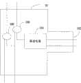
图1是本发明以太网多路分路器较佳实施例的运行环境图。Fig. 1 is an operating environment diagram of a preferred embodiment of the Ethernet demultiplexer of the present invention.
图2是图1中一个监听电路的内部结构图。FIG. 2 is an internal structure diagram of a monitoring circuit in FIG. 1 .
图3是本发明以太网多路分路方法较佳实施例的工作流程图。Fig. 3 is a working flowchart of a preferred embodiment of the Ethernet demultiplexing method of the present invention.
具体实施方式Detailed ways
如图1所示,是本发明以太网多路分路器较佳实施例的运行环境图。结点设备2通过网线5连接于终端计算机3,以太网多路分路器1旁接于网线5上。在本较佳实施例中,结点设备2为路由器或者交换机。该以太网多路分路器1监听结点设备2与终端计算机3之间传递的信号。该以太网多路分路器1还可连接网络监控设备4。该网络监控设备4多路接收以太网多路分路器1所发送的多路信号。需要指出的是,本发明以太网多路分路器1内嵌于一个配线架的内部。As shown in FIG. 1 , it is an operating environment diagram of a preferred embodiment of the Ethernet demultiplexer of the present invention. The
以太网多路分路器1包括一个以太网直流供电电源11和多个监听电路10。该直流电源11通过以太网双绞线连接远端的以太网供电(Power Over Ethernet,PoE)电源(图中未示出),并将PoE电源提供的电压转换为监听电路10需要的电压。以太网直流供电电源11为每个监听电路10提供稳压供电。每个监听电路10旁接于一条网线5上。本较佳实施例中,该网线5为双绞线。该监听电路10的个数最多为32个,每个监听电路10监听流经连接该监听电路10的一条网线5的信号,即最多可监听32条网线5的信号。每个监听电路10包括一个输出端口102,每个输出端口102通过双绞线连接网络监控设备4,网络监控设备4对信号进行分析和记录。The Ethernet demultiplexer 1 includes an Ethernet DC power supply 11 and a plurality of
如图2所示,是图1中一个监听电路10的内部结构图。该监听电路10包括输出端口102、一对探头100及驱动电路101。As shown in FIG. 2 , it is an internal structure diagram of a
驱动电路101采用高频电压跟随电路,即电压信号在该驱动电路101内被放大的倍数小于等于1。该驱动电路101具有高输入阻抗和低输出阻抗的特性。The
一对探头101通过双绞线连接于驱动电路101,驱动电路101通过双绞线连接于该监听电路10的输出端口102。该一对探头100中的每个探头100分别连接一根网线5的发送线和接收线,探头100用于监听发送线和接收线上传送的双绞线电信号(以下简称为电信号),并镜像经过网线5的电信号。A pair of
该探头100镜像电信号后,将该电信号的副本发送到驱动电路101中。该驱动电路101用于接收电信号的副本,对该电信号的副本进行跟随放大,产生符合以太网电气标准的驱动信号,并将驱动信号通过双绞线传送到输出端口102。网络监控设备4通过输出端口102接收驱动信号。After the
如图3所示,是本发明以太网多路分路器实现方法较佳实施例的作业流程图。本实施例中,以一个监测电路10为例进行说明本发明以太网多路分路方法。As shown in FIG. 3 , it is a flow chart of a preferred embodiment of the implementation method of the Ethernet demultiplexer of the present invention. In this embodiment, a
步骤S30,该监听电路10内的一对探头100监听与该一对探头100连接的网线5上的电信号。一对探头100中的每个探头分别用于监听该网线5的发送线和接收线的电信号。Step S30 , the pair of
步骤S32,探头100镜像所监听到的电信号,将该电信号的副本传递给驱动电路101。Step S32 , the
步骤S34,该驱动电路101接收电信号的副本,对该电信号的副本进行跟随放大,产生符合以太网电气标准的驱动信号。In step S34, the
步骤S36,该驱动电路101将驱动信号通过双绞线发送到该监测电路10的输出端口102。Step S36 , the
步骤S40,网络监控设备4通过连接输出端口102的双绞线获取驱动信号。Step S40 , the network monitoring device 4 obtains the driving signal through the twisted pair connected to the
最后所应说明的是,以上实施例仅用以说明本发明的技术方案而非限制,尽管参照较佳实施例对本发明进行了详细说明,本领域的普通技术人员应当理解,可以对本发明的技术方案进行修改或等同替换,而不脱离本发明技术方案的精神和范围。Finally, it should be noted that the above embodiments are only used to illustrate the technical solutions of the present invention without limitation. Although the present invention has been described in detail with reference to the preferred embodiments, those of ordinary skill in the art should understand that the technical solutions of the present invention can be The scheme shall be modified or equivalently replaced without departing from the spirit and scope of the technical scheme of the present invention.
Claims (9)
Priority Applications (1)
| Application Number | Priority Date | Filing Date | Title |
|---|---|---|---|
| CN200810217705ACN101741571A (en) | 2008-11-25 | 2008-11-25 | An Ethernet demultiplexer and its implementation method |
Applications Claiming Priority (1)
| Application Number | Priority Date | Filing Date | Title |
|---|---|---|---|
| CN200810217705ACN101741571A (en) | 2008-11-25 | 2008-11-25 | An Ethernet demultiplexer and its implementation method |
Publications (1)
| Publication Number | Publication Date |
|---|---|
| CN101741571Atrue CN101741571A (en) | 2010-06-16 |
Family
ID=42464510
Family Applications (1)
| Application Number | Title | Priority Date | Filing Date |
|---|---|---|---|
| CN200810217705APendingCN101741571A (en) | 2008-11-25 | 2008-11-25 | An Ethernet demultiplexer and its implementation method |
Country Status (1)
| Country | Link |
|---|---|
| CN (1) | CN101741571A (en) |
Cited By (4)
| Publication number | Priority date | Publication date | Assignee | Title |
|---|---|---|---|---|
| CN101986616A (en)* | 2010-10-18 | 2011-03-16 | 上海电机学院 | Ethernet branching unit and branching method thereof |
| CN102045172A (en)* | 2010-11-24 | 2011-05-04 | 上海电机学院 | E1 shunting device and method |
| CN103747068B (en)* | 2013-12-27 | 2017-07-18 | 珠海市佳讯实业有限公司 | A kind of system that TAP functions of the equipments are realized based on FPGA |
| CN107682231A (en)* | 2017-11-08 | 2018-02-09 | 湖南恒茂高科股份有限公司 | Monitor method, apparatus, computer equipment and the storage medium of PD equipment |
- 2008
- 2008-11-25CNCN200810217705Apatent/CN101741571A/enactivePending
Cited By (5)
| Publication number | Priority date | Publication date | Assignee | Title |
|---|---|---|---|---|
| CN101986616A (en)* | 2010-10-18 | 2011-03-16 | 上海电机学院 | Ethernet branching unit and branching method thereof |
| CN102045172A (en)* | 2010-11-24 | 2011-05-04 | 上海电机学院 | E1 shunting device and method |
| CN103747068B (en)* | 2013-12-27 | 2017-07-18 | 珠海市佳讯实业有限公司 | A kind of system that TAP functions of the equipments are realized based on FPGA |
| CN107682231A (en)* | 2017-11-08 | 2018-02-09 | 湖南恒茂高科股份有限公司 | Monitor method, apparatus, computer equipment and the storage medium of PD equipment |
| CN107682231B (en)* | 2017-11-08 | 2020-09-01 | 湖南恒茂高科股份有限公司 | Method and device for monitoring PD equipment, computer equipment and storage medium |
Similar Documents
| Publication | Publication Date | Title |
|---|---|---|
| US7778207B2 (en) | Passive tap and associated system for tapping network data | |
| CN101488884B (en) | Network multi-computer controller, data processing device and application method | |
| US8386846B2 (en) | Network switch with backup power supply | |
| US8027277B2 (en) | Passive network tap for tapping network data | |
| US20120023340A1 (en) | Network switch with power over ethernet | |
| US9448914B2 (en) | Method and system for implementing remote debugging | |
| US8046619B2 (en) | Apparatus and methods for data distribution devices having selectable power supplies | |
| KR101531741B1 (en) | Redundant intermediary switch solution for detecting and managing fibre channel over ethernet (fcoe) switch failures | |
| CN105103475A (en) | Method, device and system for link switching | |
| US9647879B2 (en) | Network backup device and network system | |
| US9014248B2 (en) | BASE-T common mode testing in an Ethernet subsystem | |
| JP2008131615A (en) | Communication device and program for link aggregation | |
| CN101945141A (en) | TCP-based method and system for traversing NAT devices | |
| CN101741571A (en) | An Ethernet demultiplexer and its implementation method | |
| CN100382521C (en) | Method for supporting photoelectric multiplexing of multi-gigabit Ethernet ports | |
| CN108141381B (en) | System and method to coordinate cable test results with cable test configuration | |
| US10379921B1 (en) | Fault detection and power recovery and redundancy in a power over ethernet system | |
| JP2000134228A (en) | Interface device with power feeding function, interface device with power receiving function and communication system | |
| CN102025544B (en) | Stream mirror image capturing method and device | |
| WO2007059509A2 (en) | Passive tap and associated system for tapping network data | |
| CN102893531B (en) | Wireless communication apparatus and wireless communication method | |
| CN204882744U (en) | Power equipment detection circuitry and power equipment | |
| CN107579770B (en) | Communication network system, shunt device and method for accessing unidirectional transmission network | |
| CN109698755A (en) | Method for controlling power supply, power supply unit and power receiving equipment | |
| KR101922642B1 (en) | Network Dual Switching Device |
Legal Events
| Date | Code | Title | Description |
|---|---|---|---|
| C06 | Publication | ||
| PB01 | Publication | ||
| C10 | Entry into substantive examination | ||
| SE01 | Entry into force of request for substantive examination | ||
| C12 | Rejection of a patent application after its publication | ||
| RJ01 | Rejection of invention patent application after publication | Open date:20100616 |