CN101733188A - Ball mill positioning shutdown control system and control method thereof - Google Patents
Ball mill positioning shutdown control system and control method thereofDownload PDFInfo
- Publication number
- CN101733188A CN101733188ACN201010004730ACN201010004730ACN101733188ACN 101733188 ACN101733188 ACN 101733188ACN 201010004730 ACN201010004730 ACN 201010004730ACN 201010004730 ACN201010004730 ACN 201010004730ACN 101733188 ACN101733188 ACN 101733188A
- Authority
- CN
- China
- Prior art keywords
- ball mill
- mill
- parking
- chip microcomputer
- motor
- Prior art date
- Legal status (The legal status is an assumption and is not a legal conclusion. Google has not performed a legal analysis and makes no representation as to the accuracy of the status listed.)
- Granted
Links
Images


Landscapes
- Crushing And Grinding (AREA)
Abstract
Translated fromChineseDescription
Translated fromChinese技术领域technical field
本发明涉及一种球磨机定位停车控制系统及其控制方法。The invention relates to a ball mill positioning parking control system and a control method thereof.
背景技术Background technique
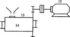
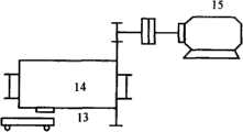
球磨机是一种工业生产中十分重要的制粉设备,广泛用于水泥、发电、选矿、陶瓷、冶金等各个行业,既是一种大型昂贵设备,同时属于一种大噪音、高能耗和低效率的设备。由于陶瓷生产工艺的特殊要求,陶瓷生产企业上所用的球磨机绝大部分都是间歇式作业模式的球磨机。如图1a、图1b所示,间歇式球磨机14有一个进出料口13,球磨机14运行前进出料口13位置应置于向上,便于原料仓装料操作,物料填装完毕启动磨机开始工作,加工完毕后需将成品从磨机内卸出,因此必须将进出料口13置于朝下,使得物料卸到输送小车或者其他运送装置,从而完成间歇式作业模式的操作。Ball mill is a very important powder-making equipment in industrial production. It is widely used in cement, power generation, mineral processing, ceramics, metallurgy and other industries. It is not only a large and expensive equipment, but also a kind of large noise, high energy consumption and low efficiency. equipment. Due to the special requirements of the ceramic production process, most of the ball mills used in ceramic production enterprises are ball mills in intermittent operation mode. As shown in Figure 1a and Figure 1b, the
间歇式作业模式的特点决定了需要对磨机停车位置实现准确控制,即对磨机的进出料口的装料位置(如:向上)和卸料位置(如:向下)的准确控制。在我国中小企业中拥有大量的这种间歇性作业的球磨机,工人对磨机进出料口的位置控制全凭借经验,一次装卸料操作往往对磨机的启停进行反复操作,从而保证进出料口的位置。因为磨机属于大惯量设备,频繁启停会造成对磨机电动机的损耗,以及对电网电压的影响,甚至影响到其他正常工作的设备,是对电力资源的浪费,不符合国家的节能降耗政策。The characteristics of the intermittent operation mode determine the need to accurately control the parking position of the mill, that is, the accurate control of the loading position (eg: upward) and unloading position (eg: downward) of the inlet and outlet of the mill. There are a large number of ball mills with intermittent operations in my country's small and medium-sized enterprises. Workers rely on experience to control the position of the inlet and outlet of the mill. One loading and unloading operation often repeatedly operates the start and stop of the mill to ensure that the inlet and outlet s position. Because the mill is a large inertia device, frequent start and stop will cause loss to the mill motor, as well as the impact on the grid voltage, and even affect other normal working equipment, which is a waste of power resources and does not meet the national energy saving and consumption reduction requirements. policy.
发明内容Contents of the invention
本发明的目的就是为解决上述问题,提供一种旨在实现节能、安全和环保三大目标,以确保其可靠经济地运行的球磨机定位停车控制系统及其控制方法。The object of the present invention is to solve the above problems and provide a ball mill positioning parking control system and its control method aiming at achieving the three goals of energy saving, safety and environmental protection to ensure its reliable and economical operation.
为实现上述目的,本发明采用如下技术方案:To achieve the above object, the present invention adopts the following technical solutions:
一种球磨机定位停车控制系统,它包括单片机,单片机与电动机转速传感器、球磨机0点位置检测装置和球磨机位置检测装置连接,输出端与继电器连接,继电器与接触器连接,接触器控制电动机同时与电源连接;单片机还与控制键盘连接;单片机通过控制接触器来控制球磨机停车位置。A ball mill positioning parking control system, which includes a single-chip microcomputer, the single-chip microcomputer is connected with the motor speed sensor, the ball mill zero position detection device and the ball mill position detection device, the output terminal is connected with the relay, the relay is connected with the contactor, and the contactor controls the motor and the power supply at the same time connection; the single-chip microcomputer is also connected with the control keyboard; the single-chip microcomputer controls the parking position of the ball mill through the control contactor.
所述控制键盘包括启动按钮、停止按钮、进料口位置按钮、出料口位置按钮和检修位置按钮。The control keyboard includes a start button, a stop button, a button for the position of the material inlet, a button for the position of the material outlet and a button for the inspection position.
所述球磨机0点位置检测装置包括设置在球磨机进料口正上方的0点位置感应点及其0点位置感应器;所述球磨机位置检测装置包括设置在球磨机圆周方向均与分布的若干个圆周位置感应点,及其相配合的圆周位置感应器。The 0-point position detection device of the ball mill includes a 0-point position sensing point and a 0-point position sensor arranged directly above the feed inlet of the ball mill; Position sensing points, and their associated circumferential position sensors.
一种球磨机定位停车控制系统的控制方法,它的步骤为:A control method for a ball mill positioning parking control system, the steps of which are:
步骤1,系统初始化,测量球磨机转速和运行时间,计算球磨机的摩擦转矩与转动惯量比:
步骤2,根据磨机断电前的初速度以及球磨机的转矩惯量比,对球磨机的断电以后所转过的角度可以进行预测;
步骤3,发出停车命令时,电动机并不马上停止,而是将停车命令发给单片机,单片机根据当前转速及起动过程得到的转矩惯量比计算得出自由停车后的角位移量,并根据当前位置,判定当磨机在何位置时关闭电动机使得磨机停止之后转到指定位置,从而实现磨机停车位置的准确控制。
所述步骤2中,预测过程为:In the
建立机电传动系统的运动方程式(1):Establish the motion equation (1) of the electromechanical transmission system:
TM——电动机产生的转矩;TM - the torque generated by the motor;
TL——传动系统的负载转矩;TL —— load torque of transmission system;
J——传动系统的转动惯量;J - the moment of inertia of the transmission system;
n——传动系统的转速;n - the speed of the transmission system;
t——转动时间t - rotation time
所述电机转矩TM:The motor torque TM :
式中,K为与电动机结构参数,是与电源频率有关的常量;S为电动机转差率,且
因此,求解方程组(3)得到[TL]′和[J]:Therefore, solving the system of equations (3) yields [TL ]′ and [J]:
Δn1、Δn2、Δn3、Δt为测量得到,而[TM]1、[TM]2和[TM]3在启动过程中是变化的,为了求解方程组(3),必须对[TM]将进行约束, 利用T=f(n)的线性关系式,在此线性关系上得到n1、n2、n3、Δn1、Δn2、Δn3、[TM]1、[TM]2和[TM]3代入方程组求解得出[TL]′和[J]。Δn1 , Δn2 , Δn3 , and Δt are measured, while [TM ]1 , [TM ]2 and [TM ]3 change during the start-up process. In order to solve equations (3), it is necessary to [TM ] will be constrained, using the linear relational expression of T=f(n), and n1 , n2 , n3 , Δn1 , Δn2 , Δn3 , [TM ]1 , [TM ]2 and [TM ]3 are substituted into the equation system and solved to obtain [TL ]′ and [J].
当磨机停车时,电动机产生的转矩[TM]=0,因此可以得到公式(4):When the mill stops, the torque generated by the motor [TM ] = 0, so the formula (4) can be obtained:
进而得到加速度公式:Then get the acceleration formula:
ε——停车时加速度;ε——acceleration when stopping;
测得停车时刻电动机的初速度ns,为系统的固有特性是由起动过程计算得到的值,Measure the initial speed ns of the motor at the moment of stopping, is the intrinsic characteristic of the system is the value calculated during the start-up process,
得到公式(6):Get formula (6):
从而预测磨机从开始停车的运动状态ns到自由停车n=0所经过的角位移量,根据角位移量得到磨机停车位置的准确控制。In this way, the angular displacement of the mill from the motion state ns of starting to stop to the free stop n=0 is predicted, and the accurate control of the parking position of the mill can be obtained according to the angular displacement.
本发明的有益效果是:通过对球磨机动力学模型的建立,分析球磨机的运行特点,实现磨机停车位置的准确控制。该控制系统通过对每次启动过程特性的自学习,利用归一化处理和系数修正方法,得到磨机运动过程中的近似等效负载扭矩和转动惯量等关键运行参数,从而预测其停止特性,根据该特性实现了大惯量磨机停止位置的准确控制。该控制系统所需硬件设备简单,安装方便,可适用于现有磨机准停控制的改造。The beneficial effects of the invention are: through the establishment of the dynamic model of the ball mill, the operation characteristics of the ball mill are analyzed, and the accurate control of the parking position of the mill is realized. The control system obtains the key operating parameters such as the approximate equivalent load torque and moment of inertia during the movement of the mill through self-learning of the characteristics of each start-up process, using normalization processing and coefficient correction methods, so as to predict its stop characteristics. Accurate control of the stop position of the large inertia mill is realized according to this characteristic. The hardware equipment required by the control system is simple, easy to install, and can be applied to the transformation of the accurate stop control of the existing mill.
附图说明Description of drawings
图1a为进料位置;Figure 1a is the feeding position;
图1b为出料位置;Figure 1b is the discharge position;
图2为球磨机运动模型;Fig. 2 is a ball mill motion model;
图3为定位原理图;Figure 3 is a schematic diagram of positioning;
图4为启动速度曲线;Fig. 4 is the starting speed curve;
图5为机械特性曲线;Fig. 5 is a mechanical characteristic curve;
图6为转速测量方法;Fig. 6 is the rotational speed measuring method;
图7a为磨机滚筒位置检测装置;Figure 7a is a mill drum position detection device;
图7b为图7a的侧面视图;Figure 7b is a side view of Figure 7a;
图8为球磨机启动过程运动曲线;Fig. 8 is the motion curve of the ball mill starting process;
图9为间歇式球磨机控制系统;Fig. 9 is the intermittent ball mill control system;
图10为控制流程图。Fig. 10 is a control flow chart.
其中,1.电动机转速传感器,2.球磨机0点位置检测装置,3.球磨机位置检测装置,4.单片机,5.继电器,6.接触器,7.电源,8.启动按钮,9.停止按钮,10.进料口位置按钮,11.出料口位置按钮,12.检修位置按钮,13.进出料口,14.球磨机,15.电动机,16.圆周位置感应点,17.0点位置感应点,18.圆周位置感应传感器。19.0点位置感应器。Among them, 1. Motor speed sensor, 2.
具体实施方式Detailed ways
下面结合附图与实施例对本发明做进一步说明。The present invention will be further described below in conjunction with the accompanying drawings and embodiments.
图9中,本发明的球磨机大惯量转子定位停车控制系统,它包括单片机4,单片机4与电动机转速传感器1、球磨机0点位置检测装置2和球磨机位置检测装置3连接,输出端与继电器5连接,继电器5与接触器6连接,接触器6控制电动机15同时与电源7连接;单片机4还与控制键盘连接;单片机4通过控制接触器6来控制球磨机14停车位置。控制键盘包括启动按钮8、停止按钮9、进料口位置按钮10、出料口位置按钮11和检修位置按钮12。In Fig. 9, the ball mill large inertia rotor positioning parking control system of the present invention includes a single-chip microcomputer 4, the single-chip microcomputer 4 is connected with the
图7a、图7b中,球磨机0点位置检测装置2包括设置在球磨机14进出料口13正上方的0点位置感应点17及其相应的0点位置感应器19;球磨机位置检测装置3包括设置在球磨机14圆周方向均与分布的若干个圆周位置感应点16及其圆周位置感应器18。为了检测球磨机14滚体位置,首先要设置0点位置,以球磨机14进出料口13的中心作为0点位置,在该处设置0点位置感应点,并在此处设置接近开关传感器作为0点位置感应器19,如图7a、图7b所示,通过该接近开关可判断磨机的0点位置。球磨机14转过角度数值的判断通过圆周位置感应点16和圆周位置感应传感器18决定。圆周位置感应点16均匀的分布在滚体端面圆周上,分布得越多则角位移检测的精度就越高。In Fig. 7a and Fig. 7b, the
图10给出了本发明的控制流程图,它的步骤为:Fig. 10 has provided the control flowchart of the present invention, and its step is:
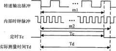
步骤1,系统初始化,测量球磨机转速和运行时间;为了测量电动机15转速在电动机15的转轴上套上一个脉冲编码器,当电机轴转动时,脉冲信号通过光电转换,经放大、滤波引入单片机。测量方法如图6所示,转速的过程为:在转速输出脉冲的下降沿启动单片机4定时器,定时长度Tc,同时记取转速输出脉冲个数m1和时钟脉冲个数m2。测量时间到,先停止对转速输出脉冲个数的计数,待下一个转速输出脉冲下降沿到来时,再停止对时钟脉冲计数,以保证测到整个转速传感器的输出脉冲。计算得出电动机15转速。根据磨机断电前的初速度以及球磨机的转矩惯量比,对球磨机的断电以后所转过的角度可以进行预测;
步骤2,发出停车命令时,电动机并不马上停止,而是将停车命令发给单片机,单片机根据当前转速计算得出自由停车后的角位移量,并根据当前位置,判定当磨机在何位置时关闭电动机使得磨机停止之后转到指定位置,从而实现磨机停车位置的准确控制。
图8为球磨机启动过程的实测运动曲线,从启动过程的加速度曲线上可以看出,启动过程经历了两个阶段:第一阶段为加速度增加的阶段,第二阶段为加速度减小的加速阶段,直到加速度减小为零,磨机进入匀速阶段。在第二阶段的加速过程中,由于球磨机的速度增加到一定值,球磨机的转差率很小,可以在启动阶段过程第二段加速过程中对测得的速度值和通过对速度值进行差分运算获得的角加速度进行一次曲线拟合,得到角加速度与角速度在第二阶段加速过程中的方程。Figure 8 is the measured motion curve of the ball mill startup process. It can be seen from the acceleration curve of the startup process that the startup process has gone through two stages: the first stage is the stage of acceleration increase, and the second stage is the acceleration stage of acceleration decrease. Until the acceleration decreases to zero, the mill enters the constant speed stage. In the acceleration process of the second stage, since the speed of the ball mill increases to a certain value, the slip rate of the ball mill is very small, and the measured speed value and the speed value can be differentiated during the second stage of the acceleration process in the start-up stage. The angular acceleration obtained by the calculation is subjected to a curve fitting to obtain the equation of the angular acceleration and the angular velocity during the second stage of acceleration.
Claims (5)
Translated fromChinesePriority Applications (1)
| Application Number | Priority Date | Filing Date | Title |
|---|---|---|---|
| CN2010100047300ACN101733188B (en) | 2010-01-13 | 2010-01-13 | Ball mill positioning parking control system and its control method |
Applications Claiming Priority (1)
| Application Number | Priority Date | Filing Date | Title |
|---|---|---|---|
| CN2010100047300ACN101733188B (en) | 2010-01-13 | 2010-01-13 | Ball mill positioning parking control system and its control method |
Publications (2)
| Publication Number | Publication Date |
|---|---|
| CN101733188Atrue CN101733188A (en) | 2010-06-16 |
| CN101733188B CN101733188B (en) | 2012-03-28 |
Family
ID=42457516
Family Applications (1)
| Application Number | Title | Priority Date | Filing Date |
|---|---|---|---|
| CN2010100047300AExpired - Fee RelatedCN101733188B (en) | 2010-01-13 | 2010-01-13 | Ball mill positioning parking control system and its control method |
Country Status (1)
| Country | Link |
|---|---|
| CN (1) | CN101733188B (en) |
Cited By (8)
| Publication number | Priority date | Publication date | Assignee | Title |
|---|---|---|---|---|
| CN102430459A (en)* | 2011-10-28 | 2012-05-02 | 彩虹(张家港)平板显示有限公司 | Glass pulverizing machine and control method thereof |
| CN105478216A (en)* | 2015-12-24 | 2016-04-13 | 山东理工大学 | Electromagnetic type swelling detecting device for compound tube mill and pre-swelling control method |
| CN105921227A (en)* | 2016-05-05 | 2016-09-07 | 中信重工机械股份有限公司 | Mechanical interlocking safety system of mill |
| CN107670835A (en)* | 2017-08-26 | 2018-02-09 | 贵州秀水旅游资源开发有限责任公司 | A kind of capsicum is pounded processing unit (plant) control system |
| CN108311218A (en)* | 2018-04-12 | 2018-07-24 | 新疆工程学院 | A kind of drum-type coal sample screening device for making |
| CN108599629A (en)* | 2018-05-07 | 2018-09-28 | 天津中德应用技术大学 | Method for improving threephase asynchronous machine positioning accuracy |
| CN109248747A (en)* | 2018-11-06 | 2019-01-22 | 蒙娜丽莎集团股份有限公司 | It is automatically positioned ball mill |
| CN110694747A (en)* | 2019-10-18 | 2020-01-17 | 江西和美陶瓷有限公司 | Ball mill ball stopping locking device, locking method and control method thereof |
Family Cites Families (3)
| Publication number | Priority date | Publication date | Assignee | Title |
|---|---|---|---|---|
| DE2823140A1 (en)* | 1978-05-26 | 1979-11-29 | Kloeckner Humboldt Deutz Ag | METHOD AND DEVICE FOR ADJUSTING A DEFINED REST POSITION OF A ROTATING TUBE |
| CN2050349U (en)* | 1989-04-27 | 1990-01-03 | 盐城工业专科学校 | Automatic controller of valve grinding of ball grinder |
| CN2266461Y (en)* | 1996-08-15 | 1997-11-05 | 云南省建筑材料科学研究设计院 | Grinding door automatic locating device for stop of ball grinder |
- 2010
- 2010-01-13CNCN2010100047300Apatent/CN101733188B/ennot_activeExpired - Fee Related
Cited By (11)
| Publication number | Priority date | Publication date | Assignee | Title |
|---|---|---|---|---|
| CN102430459A (en)* | 2011-10-28 | 2012-05-02 | 彩虹(张家港)平板显示有限公司 | Glass pulverizing machine and control method thereof |
| CN105478216A (en)* | 2015-12-24 | 2016-04-13 | 山东理工大学 | Electromagnetic type swelling detecting device for compound tube mill and pre-swelling control method |
| CN105478216B (en)* | 2015-12-24 | 2017-12-22 | 山东理工大学 | Tripe detection means that a kind of electromagnetic type multi-compartment tube grinding machine is swollen and pre-swollen tripe regulation and control method |
| CN105921227A (en)* | 2016-05-05 | 2016-09-07 | 中信重工机械股份有限公司 | Mechanical interlocking safety system of mill |
| CN105921227B (en)* | 2016-05-05 | 2018-05-22 | 中信重工机械股份有限公司 | A kind of mill mechanical interlock safety system |
| CN107670835A (en)* | 2017-08-26 | 2018-02-09 | 贵州秀水旅游资源开发有限责任公司 | A kind of capsicum is pounded processing unit (plant) control system |
| CN108311218A (en)* | 2018-04-12 | 2018-07-24 | 新疆工程学院 | A kind of drum-type coal sample screening device for making |
| CN108599629A (en)* | 2018-05-07 | 2018-09-28 | 天津中德应用技术大学 | Method for improving threephase asynchronous machine positioning accuracy |
| CN108599629B (en)* | 2018-05-07 | 2021-10-26 | 天津中德应用技术大学 | Method for improving positioning precision of three-phase asynchronous motor |
| CN109248747A (en)* | 2018-11-06 | 2019-01-22 | 蒙娜丽莎集团股份有限公司 | It is automatically positioned ball mill |
| CN110694747A (en)* | 2019-10-18 | 2020-01-17 | 江西和美陶瓷有限公司 | Ball mill ball stopping locking device, locking method and control method thereof |
Also Published As
| Publication number | Publication date |
|---|---|
| CN101733188B (en) | 2012-03-28 |
Similar Documents
| Publication | Publication Date | Title |
|---|---|---|
| CN101733188A (en) | Ball mill positioning shutdown control system and control method thereof | |
| WO2016019779A1 (en) | Method for testing braking ability of escalator by using flywheel instead of weight code | |
| CN202851391U (en) | Centrifugal pump control device | |
| CN202560636U (en) | Electronically controlled rotary-blade-adjustable axial-flow fan | |
| CN107237752B (en) | Dry vacuum pump apparatus and vacuum pumping system | |
| CN202226361U (en) | Conveyer belt control device | |
| WO2001016487A1 (en) | A pumping unit | |
| CN104310190B (en) | Staircase control system and staircase progress control method | |
| CN107289695A (en) | A kind of energy-saving control system of refrigeration compressor set | |
| CN102147283A (en) | Embedded self-energy supply wireless monitoring device of rotor equipment | |
| CN202393473U (en) | Segmented variable speed electronic belt conveyor scale | |
| CN201638085U (en) | Ball Mill Positioning Parking Control System | |
| CN204096556U (en) | A kind of plasterboard transverse shifting distance controller | |
| CN106853645A (en) | Device and method for measuring virtual position of steering gear | |
| CN102873638B (en) | Workpiece radius online detection method in excircle cutting in grinding feeding process | |
| CN202741651U (en) | Steel charging/discharging optimal control and energy-saving system for heating furnace | |
| CN210754371U (en) | Adjusting device | |
| CN114964584A (en) | A method for detecting the switching force of the action rod of a three-phase AC switch machine | |
| CN203711099U (en) | Ceramic ball mill drive system | |
| CN106685300A (en) | The Dynamic Compensation Method of Digital Variable Frequency Controller for Industrial Metering Pump | |
| CN102941947B (en) | Device and method for measuring the passing number of bottle caps on the production line | |
| CN102109856A (en) | System for identifying parameters of reaction flywheel | |
| CN110332899A (en) | A generator air gap measuring device and its measuring method | |
| CN202153144U (en) | Material level detector | |
| CN101969290A (en) | Speed sensor-free speed regulation device and method for DC motor |
Legal Events
| Date | Code | Title | Description |
|---|---|---|---|
| C06 | Publication | ||
| PB01 | Publication | ||
| C10 | Entry into substantive examination | ||
| SE01 | Entry into force of request for substantive examination | ||
| C14 | Grant of patent or utility model | ||
| GR01 | Patent grant | ||
| CF01 | Termination of patent right due to non-payment of annual fee | ||
| CF01 | Termination of patent right due to non-payment of annual fee | Granted publication date:20120328 Termination date:20130113 |