CN101727363A - Fast data recovery from HDD failure - Google Patents
Fast data recovery from HDD failureDownload PDFInfo
- Publication number
- CN101727363A CN101727363ACN200910161294ACN200910161294ACN101727363ACN 101727363 ACN101727363 ACN 101727363ACN 200910161294 ACN200910161294 ACN 200910161294ACN 200910161294 ACN200910161294 ACN 200910161294ACN 101727363 ACN101727363 ACN 101727363A
- Authority
- CN
- China
- Prior art keywords
- data
- hard disk
- disk drive
- strip
- odd
- Prior art date
- Legal status (The legal status is an assumption and is not a legal conclusion. Google has not performed a legal analysis and makes no representation as to the accuracy of the status listed.)
- Granted
Links
Images


Classifications
- G—PHYSICS
- G06—COMPUTING OR CALCULATING; COUNTING
- G06F—ELECTRIC DIGITAL DATA PROCESSING
- G06F11/00—Error detection; Error correction; Monitoring
- G06F11/07—Responding to the occurrence of a fault, e.g. fault tolerance
- G06F11/08—Error detection or correction by redundancy in data representation, e.g. by using checking codes
- G06F11/10—Adding special bits or symbols to the coded information, e.g. parity check, casting out 9's or 11's
- G06F11/1076—Parity data used in redundant arrays of independent storages, e.g. in RAID systems
- G06F11/1092—Rebuilding, e.g. when physically replacing a failing disk
Landscapes
- Engineering & Computer Science (AREA)
- Theoretical Computer Science (AREA)
- Quality & Reliability (AREA)
- Physics & Mathematics (AREA)
- General Engineering & Computer Science (AREA)
- General Physics & Mathematics (AREA)
- Techniques For Improving Reliability Of Storages (AREA)
- Information Retrieval, Db Structures And Fs Structures Therefor (AREA)
Abstract
Translated fromChinese
Description
Translated fromChinese技术领域technical field
本发明总地涉及在存储系统中的数据恢复,更特别地涉及用于从例如HDD(硬盘驱动器)故障的存储装置故障的快速数据恢复的方法和设备。本发明证明了存储数据恢复的灵活和防止磁盘故障的磁盘维护的方便使用。The present invention relates generally to data recovery in storage systems, and more particularly to methods and apparatus for fast data recovery from storage device failure, such as HDD (Hard Disk Drive) failure. The invention demonstrates the flexibility of stored data recovery and the ease of use of disk maintenance against disk failure.
背景技术Background technique
当前,RAID(独立磁盘的冗余阵列)结构通常被用于包含数据免受磁盘故障的影响。例如,RAID 5和RAID 6每个都可以从RAID组的一个磁盘故障中恢复。RAID 5和RAID 6每个在容量上都比RAID 1或RAID 10更有效。当发生磁盘故障时,存储系统将数据恢复至保留的“备用磁盘”。需要访问正常磁盘的整个区域来恢复数据。数据恢复的时间取决于磁盘容量和磁盘吞吐量性能。总的来说,容量的技术增长速率大于吞吐量的技术增长速率。结果,RAID方法对于从磁盘故障重建是缓慢的,并且将逐年更慢。长时间的数据重建可能通过重建磁盘I/O和正常磁盘I/O之间的腐蚀而引起长时间的性能恶化。长时间的数据重建也可能在数据恢复过程中面临下一个磁盘故障的问题。Currently, a RAID (Redundant Array of Independent Disks) structure is commonly used to contain data from disk failure. For example,
在基于RAIN(独立节点的冗余阵列)的另一个方法中,存储系统包括多个节点(磁盘、存储子系统等)。存储系统存储数据以适当地选择两个或多个节点。当发生节点故障时,存储系统将数据从冗余数据复制到另一节点。这可以是传导的以通过柱状(pillared)处理更好地重建性能。因为RAID方法需要保留一个或多个备用磁盘,使用RAIN方法的重建时间将比使用RAID方法的重建时间更快。RAIN方法不需要保留的备用磁盘,因为它可以将冗余数据自动地存储到空闲空间(自恢复)。另一方面,使用RAIN方法的容量有效性低于使用RAID方法的容量有效性。In another approach based on RAIN (Redundant Array of Independent Nodes), the storage system includes multiple nodes (disks, storage subsystems, etc.). The storage system stores data to select two or more nodes appropriately. When a node failure occurs, the storage system replicates the data from redundant data to another node. This can be conductive to better rebuild performance with pillared processing. Because the RAID method requires one or more spare disks to be reserved, the rebuild time using the RAIN method will be faster than that using the RAID method. The RAIN method does not require a reserved spare disk because it can automatically store redundant data to free space (self-recovery). On the other hand, the capacity efficiency using the RAIN method is lower than that using the RAID method.
发明内容Contents of the invention
本发明的实施例提供了用于从例如HDD故障的存储装置故障中的快速数据恢复的方法和设备。应用多个磁盘中的数据分布、在分布的数据中的RAID、虚拟卷和物理磁盘之间的页面映射管理、以及通过从页到页复制的并行访问数据恢复,本发明实现了快速重建、容量有效性以及自恢复。Embodiments of the present invention provide methods and apparatus for fast data recovery from storage device failure, such as HDD failure. Using data distribution among multiple disks, RAID among distributed data, page mapping management between virtual volumes and physical disks, and parallel access data recovery through page-to-page copying, the present invention achieves fast rebuilds, capacity Effectiveness and self-recovery.
根据本发明的一个方面,存储系统包括具有第一多个硬盘驱动器的第一存储装置以及控制所述第一多个硬盘驱动器的第一控制器。所述第一控制器通过数据条在所述第一多个硬盘驱动器中存储数据,每个数据条包括M个数据和N个奇偶数据,其中M和N是整数,并且所述第一控制器使用所述M个数据对每个数据条计算所述N个奇偶数据。所述每个数据条的所述M个数据和N个奇偶数据被分配到所述第一多个硬盘驱动器的M+N个硬盘驱动器。所述第一多个硬盘驱动器的第一硬盘驱动器包括所述数据条的第一数据条和所述数据条的第二数据条的数据或奇偶数据,而所述第一多个硬盘驱动器的第二硬盘驱动器包括所述数据条的所述第一数据条和所述数据条的所述第二数据条之一的数据或奇偶数据。在所述第一多个硬盘驱动器内的一个故障硬盘驱动器的故障的数据恢复的过程中,通过对于每个数据条使用所述第一多个硬盘驱动器的其它硬盘驱动器中的数据和奇偶数据的计算来对所述每个数据条恢复所述故障硬盘驱动器中的数据。According to one aspect of the present invention, a storage system includes a first storage device having a first plurality of hard disk drives and a first controller that controls the first plurality of hard disk drives. The first controller stores data in the first plurality of hard disk drives through data stripes, each data stripe includes M data and N parity data, wherein M and N are integers, and the first controller The N pieces of parity data are calculated for each data strip using the M pieces of data. The M data and N parity data of each stripe are allocated to M+N hard disk drives of the first plurality of hard disk drives. A first hard disk drive of the first plurality of hard disk drives includes data or parity data for a first one of the stripes and a second one of the stripes, and a first one of the first plurality of hard disk drives Two hard disk drives include data or parity data for one of said first one of said stripes and said second one of said stripes. In the process of data recovery of a failure of a failed hard disk drive in the first plurality of hard disk drives, by using the data and parity data in the other hard disk drives of the first plurality of hard disk drives for each stripe Calculated to restore the data in the failed hard disk drive for each of the data stripes.
在一些实施例中,所述第一多个硬盘驱动器的所述第二硬盘驱动器包括所述数据条的所述第一数据条的数据或奇偶数据。所述第一多个硬盘驱动器的第三硬盘驱动器包括所述数据条的所述第二数据条的数据或奇偶数据,并且不包括所述数据条的所述第一数据条的数据或奇偶数据。此外,M是3以及所述N是1。所述第一多个硬盘驱动器的数目是4的倍数。所述第一数据条的数据和奇偶数据被包括在所述第一多个硬盘驱动器的所述第一和第二硬盘驱动器以及所述第一多个硬盘驱动器的第四和第五硬盘驱动器中。所述第二数据条的数据和奇偶数据被包括在所述第一多个硬盘驱动器的所述第一、第三、第四、第五硬盘驱动器中。In some embodiments, said second hard drive of said first plurality of hard drives includes data or parity data of said first stripe of said stripes. A third hard disk drive of said first plurality of hard disk drives includes data or parity data for said second one of said stripes and does not include data or parity data for said first one of said stripes . Also, M is 3 and the N is 1. The number of the first plurality of hard disk drives is a multiple of 4. The data and parity data of the first stripe is included in the first and second hard disk drives of the first plurality of hard disk drives and in the fourth and fifth hard disk drives of the first plurality of hard disk drives . The data and parity data of the second stripe are included in the first, third, fourth, and fifth hard disk drives of the first plurality of hard disk drives.
在特定实施例中,存储系统还包括具有第二多个硬盘驱动器的第二存储装置以及控制所述第二多个硬盘驱动器的第二控制器。从所述第二存储装置接收由所述第一控制器存储的所述数据。所述第一控制器包括多个处理器。当从所述第二存储装置向所述第一存储装置转移数据时,所述第二硬盘驱动器和所述第三硬盘驱动器由所述多个处理器的不同处理器同时访问。存储系统还包括具有所述第一多个硬盘驱动器的未分配的硬盘驱动器的容量池卷。从所述容量池卷分配所述数据条。响应于从所述第二存储装置接收所述数据来进行每个数据条的所述分配。每个数据条的所述N个奇偶数据通过不同总线被连接至所述第一控制器。In a particular embodiment, the storage system further includes a second storage device having a second plurality of hard disk drives and a second controller that controls the second plurality of hard disk drives. The data stored by the first controller is received from the second storage device. The first controller includes a plurality of processors. The second hard disk drive and the third hard disk drive are simultaneously accessed by different ones of the plurality of processors when transferring data from the second storage device to the first storage device. The storage system also includes a capacity pool volume having unallocated hard disk drives of the first plurality of hard disk drives. The stripe is allocated from the capacity pool volume. The allocating of each data stripe occurs in response to receiving the data from the second storage device. The N parity data of each data strip are connected to the first controller through different buses.
在一些实施例中,存储系统还包括具有第二多个硬盘驱动器的第二存储装置以及控制所述第二多个硬盘驱动器的第二控制器。从所述第二存储装置接收由所述第一控制器存储的所述数据。所述第一控制器并行处理所述第一和第二数据条的数据和奇偶数据。所述第一控制器包括表,所述表包括将所述每个数据条分配到所述第一多个硬盘驱动器的信息。M是6以及所述N是2。所述第一多个硬盘驱动器的数目是8的倍数。在从包括所述第一多个硬盘驱动器的一个的故障的所述数据条的一个读取数据的情况下,控制所述第一控制器来仅访问所述第一多个硬盘驱动器的7个硬盘驱动器而不访问故障的硬盘驱动器。存储系统还包括具有所述第一多个硬盘驱动器的未分配的硬盘驱动器的容量池卷。从所述容量池卷分配所述数据条。存储系统还包括具有第二多个硬盘驱动器的第二存储装置以及控制所述第二多个硬盘驱动器的第二控制器。响应于从所述第二存储装置接收所述数据来进行每个数据条的所述分配。In some embodiments, the storage system further includes a second storage device having a second plurality of hard drives and a second controller that controls the second plurality of hard drives. The data stored by the first controller is received from the second storage device. The first controller processes data and parity data of the first and second stripes in parallel. The first controller includes a table including information to assign the each stripe to the first plurality of hard disk drives. M is 6 and the N is 2. The number of the first plurality of hard disk drives is a multiple of 8. controlling said first controller to access only seven of said first plurality of hard drives in the event of reading data from one of said stripes comprising a failure of one of said first plurality of hard drives hard drive without accessing the failed hard drive. The storage system also includes a capacity pool volume having unallocated hard disk drives of the first plurality of hard disk drives. The stripe is allocated from the capacity pool volume. The storage system also includes a second storage device having a second plurality of hard drives and a second controller that controls the second plurality of hard drives. The allocating of each data stripe occurs in response to receiving the data from the second storage device.
根据本发明的另一个方面,提供了一种数据恢复的方法,用于包括具有第一多个硬盘驱动器的第一存储装置和控制所述第一多个硬盘驱动器的第一控制器的存储系统中,所述方法包括:通过数据条在所述第一控制器的所述第一多个硬盘驱动器中存储数据,每个数据条包括M个数据和N个奇偶数据,其中M和N是整数,并且所述第一控制器使用所述M个数据对每个数据条计算所述N个奇偶数据;将所述每个数据条的所述M个数据和N个奇偶数据分配到所述第一多个硬盘驱动器的M+N个硬盘驱动器,其中所述第一多个硬盘驱动器的第一硬盘驱动器包括所述数据条的第一数据条和所述数据条的第二数据条的数据或奇偶数据,而所述第一多个硬盘驱动器的第二硬盘驱动器包括所述数据条的所述第一数据条和所述数据条的所述第二数据条之一的数据或奇偶数据;在所述第一多个硬盘驱动器的一个故障硬盘驱动器的故障的数据恢复的过程中,通过对于每个数据条使用所述第一多个硬盘驱动器的其它硬盘驱动器中的数据和奇偶数据的计算来对所述每个数据条恢复所述故障硬盘驱动器中的数据。According to another aspect of the present invention, there is provided a data recovery method for a storage system comprising a first storage device having a first plurality of hard disk drives and a first controller controlling the first plurality of hard disk drives In the method, the method includes: storing data in the first plurality of hard disk drives of the first controller through data stripes, each data stripe including M data and N parity data, wherein M and N are integers , and the first controller calculates the N parity data for each data strip using the M data; distributes the M data and N parity data of each data strip to the first M+N hard disk drives of a plurality of hard disk drives, wherein a first hard disk drive of said first plurality of hard disk drives includes data from a first one of said stripes and a second one of said stripes or parity data, and a second hard disk drive of said first plurality of hard disk drives includes data or parity data for one of said first one of said stripes and said second one of said stripes; In the process of data recovery of a faulty hard disk drive of the first plurality of hard disk drives, by using data and parity data in other hard disk drives of the first plurality of hard disk drives for each data stripe The data in the failed hard disk drive is restored for each of the data stripes.
本发明的另一个方面提供了一种计算机可读介质,用于包括具有第一多个硬盘驱动器的第一存储装置和控制所述第一多个硬盘驱动器的第一控制器的存储系统中,存储多个指令以控制数据处理器执行数据恢复。计算机可读介质包括:使得数据处理器通过数据条在所述第一多个硬盘驱动器中存储数据的指令,每个数据条包括M个数据和N个奇偶数据,其中M和N是整数,并且所述第一控制器使用所述M个数据对每个数据条计算所述N个奇偶数据;将所述每个数据条的所述M个数据和N个奇偶数据分配到所述第一多个硬盘驱动器的M+N个硬盘驱动器的指令,其中所述第一多个硬盘驱动器的第一硬盘驱动器包括所述数据条的第一数据条和所述数据条的第二数据条的数据或奇偶数据,而所述第一多个硬盘驱动器的第二硬盘驱动器包括所述数据条的所述第一数据条和所述数据条的所述第二数据条之一的数据或奇偶数据;以及在所述第一多个硬盘驱动器的一个故障硬盘驱动器的故障的数据恢复的过程中,通过对于每个数据条使用所述第一多个硬盘驱动器的其它硬盘驱动器中的数据和奇偶数据的计算来对所述每个数据条恢复所述故障硬盘驱动器中的数据的指令。数据处理器可以位于第一控制器中。Another aspect of the present invention provides a computer readable medium for use in a storage system comprising a first storage device having a first plurality of hard disk drives and a first controller controlling the first plurality of hard disk drives, A plurality of instructions are stored to control the data processor to perform data recovery. The computer-readable medium includes instructions for causing the data processor to store data in the first plurality of hard disk drives in stripes, each stripe including M data and N parity data, where M and N are integers, and The first controller uses the M data to calculate the N parity data for each data strip; and distributes the M data and N parity data of each data strip to the first multiple Instructions for M+N hard disk drives of the hard disk drives, wherein the first hard disk drive of the first plurality of hard disk drives includes the data of the first data strip of the data strips and the second data strip of the data strips or parity data, and a second hard disk drive of the first plurality of hard disk drives includes data or parity data for one of the first one of the stripes and the second one of the stripes; and In the process of recovering data from a failure of a failed hard disk drive of the first plurality of hard disk drives, by calculating data and parity data in other hard disk drives of the first plurality of hard disk drives for each data stripe An instruction to restore data in the failed hard disk drive for each of the data stripes. A data processor may be located in the first controller.
通过特定实施例的具体实施方式,本发明的这些和其它特征和优点对于本领域的普通技术人员来说是显而易见的。These and other features and advantages of the invention will be apparent to those of ordinary skill in the art from the detailed description of the particular embodiments.
附图说明Description of drawings
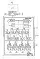
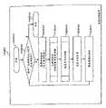
图1表示可以应用本发明的方法和设备的系统的硬件配置;Fig. 1 represents the hardware configuration of the system that can apply method and equipment of the present invention;
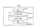
图2表示根据本发明的第一实施例的图1的存储子系统中的存储器的例子;FIG. 2 shows an example of a memory in the storage subsystem of FIG. 1 according to a first embodiment of the present invention;
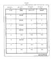
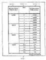
图3表示图2的存储器中的RAID组管理表的例子;Fig. 3 shows the example of the RAID group management table in the memory of Fig. 2;
图4表示图2的存储器中的虚拟卷管理表的例子;FIG. 4 shows an example of a virtual volume management table in the memory of FIG. 2;
图5表示图2的存储器中的虚拟卷页面管理表的例子;FIG. 5 shows an example of a virtual volume page management table in the memory of FIG. 2;
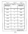
图6表示图2的存储器中的容量池组块(chunk)管理表的例子;FIG. 6 shows an example of a capacity pool chunk (chunk) management table in the memory of FIG. 2;
图7表示图2的存储器中的容量池页面管理表的例子;FIG. 7 shows an example of a capacity pool page management table in the memory of FIG. 2;
图8表示图2的存储器中的高速缓存管理表的例子;FIG. 8 shows an example of a cache management table in the memory of FIG. 2;
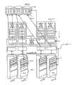
图9表示具有均包括多个信息包(parcel)的八个HDD的5×2个RAID组的例子;Figure 9 shows an example of 5 x 2 RAID groups with eight HDDs each including a plurality of parcels;
图10表示具有均包括多个数据条的多个信息包的组块的例子;FIG. 10 shows an example of a chunk having a plurality of packets each comprising a plurality of data strips;
图11表示具有多个页面的组块的例子;Figure 11 shows an example of a chunk with multiple pages;
图12表示具有多个页面的虚拟卷的例子;Figure 12 shows an example of a virtual volume with multiple pages;
图13表示具有多个槽(slot)的页面的例子;Figure 13 shows an example of a page with a plurality of slots;
图14表示虚拟卷及其虚拟卷管理表和虚拟卷页面管理表的例子;Fig. 14 represents the example of virtual volume and its virtual volume management table and virtual volume page management table;
图15表示对于在图14的虚拟卷中的容量池的表参考结构的例子;FIG. 15 shows an example of a table reference structure for a capacity pool in the virtual volume of FIG. 14;
图16表示对于虚拟卷的表参考结构的例子;FIG. 16 shows an example of a table reference structure for a virtual volume;
图17表示在图2的存储器中的写I/O控制的处理流程的例子;FIG. 17 shows an example of the processing flow of write I/O control in the memory of FIG. 2;
图18表示在图2的存储器中的读I/O控制的处理流程的例子;Fig. 18 shows an example of the processing flow of the read I/O control in the memory of Fig. 2;
图19表示在图2的存储器中的登台(staging)控制的处理流程的例子;Fig. 19 shows an example of the processing flow of the staging (staging) control in the memory of Fig. 2;
图20表示在图2的存储器中的离台(destaging)控制的处理流程的例子;Fig. 20 shows an example of the processing flow of the destaging control in the memory of Fig. 2;
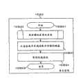
图21表示在图2的存储器中的复制控制的处理流程的例子;Fig. 21 shows an example of the processing flow of copy control in the memory of Fig. 2;
图22表示在图2的存储器中的奇偶计算控制的处理流程的例子;Fig. 22 shows an example of the processing flow of parity calculation control in the memory of Fig. 2;
图23表示在图2的存储器中的物理磁盘地址控制的处理流程的例子;Fig. 23 shows the example of the processing flow of the physical disk address control in the memory of Fig. 2;
图24表示在图2的存储器中的刷新(flush)控制的处理流程的例子;Fig. 24 shows an example of the processing flow of refresh (flush) control in the memory of Fig. 2;
图25表示在图2的存储器中的高速缓存控制的处理流程的例子;Fig. 25 shows an example of the processing flow of the cache control in the memory of Fig. 2;
图26表示在图2的存储器中的页面检测控制(A)的处理流程的例子;FIG. 26 shows an example of the processing flow of the page detection control (A) in the memory of FIG. 2;
图27表示在图2的存储器中的页面检测控制(B)的处理流程的例子;FIG. 27 shows an example of the processing flow of the page detection control (B) in the memory of FIG. 2;
图28表示在图2的存储器中的页面转移控制的处理流程的例子;Fig. 28 shows an example of the processing flow of page transfer control in the memory of Fig. 2;
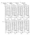
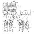
图29表示通过组块和页面复制的数据恢复的例子;Figure 29 shows an example of data recovery by chunk and page copy;
图30表示图29的数据恢复的总结和时序;Figure 30 represents the summary and timing of the data recovery of Figure 29;
图31表示通过组块和页面复制的数据恢复的整体时序;Figure 31 shows the overall timing of data recovery through chunk and page copy;
图32表示根据本发明的第二实施例的图1的存储子系统中的存储器的例子;FIG. 32 shows an example of a memory in the storage subsystem of FIG. 1 according to a second embodiment of the present invention;
图33表示在图32的存储器中的HDD管理表的例子;Fig. 33 shows an example of the HDD management table in the memory of Fig. 32;
图34表示在图32的存储器中的虚拟卷管理表的例子;FIG. 34 shows an example of a virtual volume management table in the memory of FIG. 32;
图35表示在图32的存储器中的虚拟卷页面管理表的例子;FIG. 35 shows an example of a virtual volume page management table in the memory of FIG. 32;
图36表示在图32的存储器中的容量池组块管理表的例子;FIG. 36 shows an example of a capacity pool chunk management table in the memory of FIG. 32;
图37表示虚拟卷及其虚拟卷管理表和虚拟卷页面管理表的例子;Fig. 37 shows the example of virtual volume and its virtual volume management table and virtual volume page management table;
图38表示对于图37的虚拟卷中的容量池的表参考结构的例子;FIG. 38 shows an example of a table reference structure for a capacity pool in the virtual volume of FIG. 37;
图39表示在图32的存储器中的页面检测控制(A)的处理流程的例子;以及Figure 39 shows an example of the processing flow of the page detection control (A) in the memory of Figure 32; and
图40表示在图32的存储器中的页面转移控制的处理流程的例子。FIG. 40 shows an example of the processing flow of page transfer control in the memory of FIG. 32 .
具体实施方式Detailed ways
在本发明的下述具体实施方式中,参考形成本揭示的一部分的附图,附图通过说明示例实施例的方式而不是限制示例实施例的方式示出,通过示例实施例可以实施本发明。在附图中,相似的附图标记描述各个图中基本相似的部件。进一步地,应该注意到尽管如下所述并且如图所说明的具体实施方式提供了各种示例实施例,本发明不限于这里描述和说明的实施例,而是能够延伸到如同本领域普通技术人员所知或会知道的其它实施例。说明书中引用的″一个实施例″、″该实施例″、或″这些实施例″的意思是联系实施例所描述的特定特征、结构或特点包括在本发明的至少一个实施例中,并且在说明书的各个地方出现的这些短语不是必须地指的是相同的实施例。另外,在下述具体实施方式中,提出多个特定细节从而提供对本发明的详细理解。然而,对本领域普通技术人员来说将显而易见不是必须所有的这些特定细节才能实施本发明。在其它环境下,公知的结构、材料、电路、处理和接口没有详细描述,和/或可以用框图的形式说明,从而不会不必要地使本发明模糊。In the following detailed description of the invention, reference is made to the accompanying drawings which form a part hereof and which are shown by way of illustration and not limitation of example embodiments by which the invention may be practiced. In the drawings, like reference numerals describe substantially similar components in various figures. Further, it should be noted that although the detailed description described below and illustrated in the drawings provides various exemplary embodiments, the present invention is not limited to the embodiments described and illustrated herein, but extends to other embodiments that are or become known. Reference in the specification to "one embodiment," "the embodiment," or "these embodiments" means that a particular feature, structure, or characteristic described in connection with the embodiment is included in at least one embodiment of the invention and is included in The appearances of these phrases in various places in the specification are not necessarily referring to the same embodiment. Additionally, in the following detailed description, numerous specific details are set forth in order to provide a detailed understanding of the invention. It will be apparent, however, to one skilled in the art that not all of these specific details are required to practice the present invention. In other instances, well-known structures, materials, circuits, processes and interfaces have not been described in detail, and/or may be illustrated in block diagram form in order not to unnecessarily obscure the present invention.
此外,通过计算机中操作的算法和符号表达来表述下面具体实施方式中的一些部分。这些算法描述和符号表达是在数据处理领域的普通技术人员使用的以最有效地将它们的创新实质传递给本领域的其它普通技术人员的手段。算法是一系列定义的步骤以导致期望的结束状态和结果。在本发明中,执行的步骤需要切实的物理量操作以实现切实的结果。尽管并不必须,通常这些量采用电或磁信号的形式,或者是能够被存储、传递、合并、比较和操作的指令的形式。为了共用的原因,已经多次被证明将这些信号参考为比特、值、元件、符号、字符、术语、数字、指令等是方便的。然而,应该牢记所有这些和类似的术语与恰当的物理量相关联,并且仅为施加到这些量上的方便的标签。除非另行提及,如从下面的讨论中显而易见,应该理解到在整个说明书中,利用例如“处理”、“计算”、“确定”、“显示”等的术语的讨论可以包括计算机系统或其它信息处理装置的行为和处理,该计算机系统或其它信息处理装置将在计算机系统的寄存器和存储器中的表示为物理(电子)量的数据操作和转换为计算机系统的存储器或寄存器或其它信息存储、传输和显示装置内的类似地表示为物理量的其它数据。Furthermore, some parts of the following detailed description are expressed by algorithms and symbolic expressions operating on a computer. These algorithmic descriptions and symbolic representations are the means used by those skilled in the data processing arts to most effectively convey the substance of their innovations to others skilled in the art. An algorithm is a defined sequence of steps leading to a desired end state and result. In the present invention, steps are performed that require manipulation of tangible physical quantities to achieve tangible results. Usually, though not necessarily, these quantities take the form of electrical or magnetic signals, or instructions capable of being stored, transferred, combined, compared, and manipulated. It has proven convenient at times, for reasons of common usage, to refer to these signals as bits, values, elements, symbols, characters, terms, numbers, instructions, or the like. It should be borne in mind, however, that all of these and similar terms are to be to be associated with the appropriate physical quantities and are merely convenient labels applied to these quantities. Unless otherwise mentioned, as is apparent from the discussion that follows, it should be understood that throughout this specification, discussions using terms such as "process," "calculate," "determine," "display," etc. may include computer systems or other information The behavior and processing of a processing device that manipulates and converts data represented as physical (electronic) quantities in the computer system's registers and memories into the computer system's memory or registers or other information storage, transmission Other data expressed as physical quantities similarly to those in the display device.
如将在下面更详细地描述的,本发明的示例实施例提供了用于从存储装置故障中进行快速数据恢复的设备、方法和计算机程序。As will be described in more detail below, example embodiments of the present invention provide apparatus, methods and computer programs for fast data recovery from storage device failure.
图1表示可以应用本发明的方法和设备的系统的硬件配置。存储子系统100通过SAN(存储区域网络)连接至主机计算机300。存储子系统100包括存储控制器110和磁盘单元120。存储控制器110具有CPU 111用于控制存储子系统100、运行程序以及使用存储器112中存储的表格。除了程序和表格,存储器112还存储数据。提供信道接口113以和SAN 200进行接口。存储控制器110包括链接到磁盘单元120中的磁盘121a到121d的磁盘接口115a到115d。存储控制器110还包括数据传递控制器116a到116d,用于在存储器112和磁盘121之间传递数据,以及计算数据以产生奇偶数据或恢复数据。磁盘单元120提供非易失性磁盘121用于存储数据。FIG. 1 shows the hardware configuration of a system to which the method and apparatus of the present invention can be applied. The
第一实施例first embodiment
图2表示根据本发明的第一实施例在图1的存储子系统100中的存储器112的例子。存储器112包括卷管理表121-11,卷管理表121-11具有用于磁盘121和那些组(图3)的物理结构管理的RAID组管理表112-11-1,以及用于卷配置管理(图4)的虚拟卷管理表112-11-2。提供高速缓存管理表112-14(图8)用于管理高速缓存数据区域112-30和用于LRU/MRU管理。精简供应管理表112-15包括用于从虚拟卷的部分到容量池的部分参考管理的虚拟卷页面管理表112-15-1(图5)、用于容量池的源管理和从容量池页面到虚拟卷页面的参考管理的容量池组块管理表112-15-2(图6)、以及用于容量池组块的资源管理的容量池页面管理表112-15-3(图7)。卷I/O控制112-21包括写I/O控制112-21-1(图17)和读I/O控制112-21-2(图18),写I/O控制112-21-1通过写I/O要求运行并且通过信道接口113接收写数据并存储到高速缓存数据区域112-30,读I/O控制112-21-2通过读I/O要求运行并且通过信道接口113发送来自高速缓存数据区域112-30的读数据。物理磁盘控制112-22包括从磁盘121到高速缓存数据区域112-30传递数据的登台控制112-22-1(图19)、从高速缓存数据区域112-30到磁盘121传递数据的离台控制112-22-2(图20)、复制在高速缓存数据区域112-30中的数据的复制控制112-22-3(图21)、计算存储在磁盘121中的冗余数据并且恢复在磁盘121中的丢失数据的奇偶计算控制112-22-4(图22)、以及计算和解析容量池数据的物理地址的物理磁盘地址控制112-22-5(图23)。存储器112还包括周期性地将脏的垃圾(dirty)数据从高速缓存数据区域112-30刷新到磁盘121的刷新控制器112-23(图24)、以及发现在高速缓存数据区域112-30中的高速缓存的数据并且在高速缓存数据区域112-20中分配新的高速缓存区域的高速缓存控制112-24(图25)。精简供应管理112-15包括用于搜索由虚拟卷参考的容量池页面的页面检测控制112-25-1(图26)(如果没有向虚拟卷页面分配容量池页面,向虚拟卷页面分配新的容量池页面)、用于搜索由虚拟卷页面参考的容量池页面的页面检测控制112-25-2(图6)(如果没有向虚拟卷页面分配容量池页面,则回答“零保留页面”地址)、以及当磁盘故障发生时将容量池页面转移到其它容量池页面的页面转移控制112-25-3(图28)。存储器112包括控制运行的程序的进度、支持多任务环境的核112-40。如果程序等待ack(确认),CPU 111改为运行另一个任务(例如从磁盘121到高速缓存数据区域112-30的数据转移等待)。高速缓存数据区域112-30存储读取和写入高速缓存数据,并且被分离到多个高速缓存槽。FIG. 2 shows an example of
图3表示在图2的存储器112中的RAID组管理表112-11-1的例子。RAID组管理表112-11-1包括以下列:作为RAID组的ID的RAID组号112-11-1-1,以及表示RAID组的结构的RAID级别112-11-1-2。例如,“5×N”(N是数字)意味着“RAID级别是5(3D+1P)”以及“由8N个HDD构成”。“N/A”意味着RAID组不存在。RAID组管理表112-11-1还包括以下列:表示属于RAID组的HDD的ID列表的HDD号码112-11-1-3、表示除了冗余区域的RAID组的全部容量的RAID组容量112-11-1-4、用于管理未使用的精简供应组块的空闲组块队列索引112-11-1-5、以及用于管理使用的精简供应组块的使用的组块队列索引112-11-1-6。FIG. 3 shows an example of the RAID group management table 112-11-1 in the
图4表示图2的存储器112中的虚拟卷管理表112-11-2的例子。虚拟卷管理表112-11-2包括以下列:表示虚拟卷ID的虚拟卷号码112-11-2-1、表示虚拟卷的容量的虚拟卷容量112-11-2-2(“N/A”意味着虚拟卷不存在),表示虚拟卷当前使用的组块的RAID组ID的使用RAID组号码112-11-2-3,以及表示表示虚拟卷当前使用的组块ID的使用组块号码或使用容量池组块号码112-11-2-4。FIG. 4 shows an example of the virtual volume management table 112-11-2 in the
图5表示在图2的存储器112中的虚拟卷页面管理表112-15-1的例子。虚拟卷页面管理表112-15-1包括以下列:表示虚拟卷页面的顶部地址的虚拟卷页面索引112-15-1-1、表示虚拟卷页面所属的RAID组ID的RAID组号码112-15-1-2(“N/A”意味着没有向虚拟卷页面分配容量池页面)、以及表示虚拟卷页面参考的容量池页面的顶部地址的容量池页面索引112-15-1-3。FIG. 5 shows an example of the virtual volume page management table 112-15-1 in the
图6表示图2的存储器112中的容量池组块管理表112-15-2的例子。容量池组块管理表112-15-2包括以下列:表示容量池组块的ID的容量池组块号码112-15-2-1、表示容量池组块参考的虚拟卷ID的虚拟卷号码112-15-2-2、表示容量池组块的使用的容量的使用的容量112-15-2-3、表示当已经使用了区域时容量池组块的移除的容量的删除的容量112-15-2-4、表示用于队列管理的前一组块指针的前一组块号码112-15-2-5、以及表示用于队列管理的后一组块指针的后一组块号码112-15-2-6(“NULL”意味着队列的终止)。FIG. 6 shows an example of the capacity pool chunk management table 112-15-2 in the
图7表示在图2的存储器112中的容量池页面管理表112-15-3的例子。容量池页面管理表112-15-3包括以下列:表示容量池页面的ID的容量池页面索引112-15-3-1,以及表示容量池页面参考的虚拟卷页面的ID的虚拟卷页面号码112-15-3-2(“NULL”意味着容量池页面未被使用)。FIG. 7 shows an example of the capacity pool page management table 112-15-3 in the
图8表示在图2的存储器112中的高速缓存管理表112-14的例子。高速缓存管理表112-14包括以下列:表示高速缓存数据区域112-30中的高速缓存槽的ID的高速缓存槽号码112-14-1、表示高速缓存槽在其中存储数据的磁盘121的ID的磁盘号码112-14-2、表示高速缓存槽在其中存储数据的磁盘地址的磁盘地址112-14-3、表示用于队列管理的下一高速缓存槽号码的下一槽指针112-14-4(“NULL”意味着队列的终止)、表示高速缓存槽队列的种类的队列种类的信息112-14-5(“空闲”意味着具有未使用的高速缓存槽的队列、“干净”意味着具有与磁盘槽存储相同数据的高速缓存槽的队列、“脏的”意味着具有与磁盘间隙存储不同数据的高速缓存槽的队列,所以将来存储控制器110需要将高速缓存槽数据刷新到磁盘槽中)、表示高速缓存槽队列的索引的队列索引指针112-14-6。FIG. 8 shows an example of the cache management table 112-14 in the
提供图9-11来显示数据校准。图9表示具有均包括多个“信息包”的8个HDD的5×2RAID组的例子。信息包由相同HDD的连续的多个数据条组成。图10表示具有均包括多个数据条的多个信息包的组块的例子。磁盘121a、121b、121c、121d、121e、121f、121g和121h组成RAID组。该RAID组的RAID级别在RAID级别2-11-1-2中被表示为“5×2”。每个磁盘被划分为多个信息包121-4。每个信息包121-4被划分成多个容量池数据条121-3。四个信息包121-4构成组块121-1。组块121-1中的四个信息包121-4的每一个属于连接至不同磁盘接口115a-115d的一个磁盘121以避免两个点的故障。这四个数据包121-4的选择遵守平均分配的算法。每个组块121-1具有构成冗余阵列的多个容量池数据条121-3。如图11所示,每个组块121-1被划分为多个容量池页面121-2。每个容量池页面121-2是精简供应分配单元。每个容量池页面121-2包括多个容量池数据条121-3。Figures 9-11 are provided to show data calibration. Fig. 9 shows an example of a 5x2 RAID group with 8 HDDs each including a plurality of "packets". A packet consists of consecutive multiple data strips of the same HDD. Fig. 10 shows an example of a chunk having a plurality of packets each including a plurality of data pieces. The
通常,存储控制器通过数据条在硬盘驱动器中存储数据,每个数据条包括M个数据和N个奇偶数据,其中M和N是整数,并且存储控制器使用M个数据对每个数据条计算N个奇偶数据。每个数据条的M个数据和N个奇偶数据被分配到M+N个硬盘驱动器。第一硬盘驱动器包括所述数据条的第一数据条和所述数据条的第二数据条的数据或奇偶数据,而第二硬盘驱动器包括所述数据条的所述第一数据条和所述数据条的所述第二数据条之一的数据或奇偶数据。在涉及一个硬盘驱动器的故障的数据恢复的过程中,如下面结合图29-31详细描述的那样,通过对于每个数据条使用所述第一多个硬盘驱动器的其它硬盘驱动器中的数据和奇偶数据的计算来对所述每个数据条恢复所述故障硬盘驱动器中的数据。Generally, the storage controller stores data in the hard disk drive by data strips, each data strip includes M data and N parity data, where M and N are integers, and the storage controller uses M data to calculate N parity data. M data and N parity data of each stripe are allocated to M+N hard disk drives. A first hard disk drive includes data or parity data for a first one of said stripes and a second one of said stripes, and a second hard disk drive includes said first one of said stripes and said second one of said stripes. Data or parity data of one of said second ones of the stripes. During data recovery involving a failure of one hard drive, as described in detail below in conjunction with FIGS. Data calculation to restore the data in the failed hard disk drive for each of the data stripes.
在某些情况下,第二硬盘驱动器包括数据条的第一数据条的数据或奇偶数据。第三硬盘驱动器包括数据条的第二数据条的数据或奇偶数据,并且不包括数据条的第一数据条的数据或奇偶数据。此外,M是3以及N是1。硬盘驱动器的数目是4的倍数。第一数据条的数据和奇偶数据被包括在第一和第二硬盘驱动器以及第四和第五硬盘驱动器中。第二数据条的数据和奇偶数据被包括在第一、第三、第四、第五硬盘驱动器中。当从另一存储装置向当前存储装置转移数据时,第二硬盘驱动器和第三硬盘驱动器由多个不同处理器同时访问。每个数据条的N个奇偶数据通过不同总线连接至第一控制器。In some cases, the second hard drive includes data or parity data for the first stripe of stripes. The third hard disk drive includes data or parity data for a second one of the stripes and does not include data or parity data for a first one of the stripes. Also, M is 3 and N is 1. The number of hard disk drives is a multiple of 4. Data and parity data of the first stripe are included in the first and second hard disk drives and the fourth and fifth hard disk drives. The data and parity data of the second stripe are included in the first, third, fourth and fifth hard disk drives. When transferring data from another storage device to the current storage device, the second hard drive and the third hard drive are simultaneously accessed by a plurality of different processors. The N parity data of each data strip are connected to the first controller through different buses.
图12表示具有多个虚拟卷页面141-2的虚拟卷141的例子。除了冗余容量之外,虚拟卷页面141-2的大小等于容量池页面121-2的大小。如图13所示,虚拟卷页面141-2被划分为虚拟卷槽141-3。除了容量数据条之外,在一个虚拟卷页面141-2中的虚拟卷槽141-3的数目等于在一个容量池页面121-2中的容量池数据条121-3的数目。FIG. 12 shows an example of a
图14表示虚拟卷141及其虚拟卷管理表112-11-2和虚拟卷页面管理表112-15-1的例子。实箭头线意味着指针参考的对象(从虚拟卷页面管理表112-15-1到容量池组块121-1以及容量池页面121-2),而虚箭头线意味着计算参考的对象(在虚拟卷141和管理表112-11-2和112-15-1之中)。虚拟卷141和虚拟卷管理表112-11-2处于一对一的关系。虚拟卷管理表112-11-2显示使用当前容量池组块121-1的容量。虚拟卷页面141-2和虚拟卷页面管理表112-15-1处于一对一的关系。如果页面被分配,虚拟卷页面管理表112-15-1参考容量池页面121-2。Fig. 14 shows an example of the
图15表示对于图14的虚拟卷141中的容量池的表参考结构的例子。实箭头线意味着指针参考的对象(从容量池页面管理表112-15-3和RAID组管理表112-11-1到虚拟卷141和虚拟卷页面141-2,以及从RAID组管理表112-11-1到容量池组块121-1)。虚箭头线意味着计算参考的对象(在容量池页面管理表112-15-3、容量池组块管理表112-15-2、RAID组管理表112-11-1、以及RAID组(包括容量池组块121-1和容量池页面121-2)之中)。RAID组和RAID组管理表112-11-1处于一对一的关系。RAID组管理表112-11-1参考使用的和未使用的容量池组块112-1。容量池组块121-1和容量池组块管理表112-15-2处于一对一的关系。容量池组块管理表112-15-2参考虚拟卷141。容量池页面121-2和容量池页面管理表112-15-3处于一对一的关系。容量池页面管理表112-15-3参考虚拟卷页面141-2。FIG. 15 shows an example of the table reference structure for the capacity pool in the
图16表示对于虚拟卷141的表参考结构的例子。实箭头线意味着指针参考的对象(从高速缓存管理表112-14到虚拟卷槽141-3以及容量池数据条121-3)。虚箭头线意味着计算参考的对象(在高速缓存管理表112-14和高速缓存槽112-30-1之间)。高速缓存数据区域112-30被划分为多个高速缓存槽112-30-1。高速缓存槽112-30-1的大小等于容量池数据条121-3的大小并且等于虚拟卷槽141-3的大小。高速缓存管理表112-14和高速缓存槽112-30-1处于一对一的关系。高速缓存管理表112-14参考虚拟卷槽141-3和容量池数据条121-3。FIG. 16 shows an example of the table reference structure for the
图17表示图2的存储器112中的写I/O控制112-21-1的处理流程的例子。程序从112-21-1-1开始。在步骤112-21-1-2,程序调用缓冲控制112-24来搜索高速缓存槽112-30-1。在步骤112-21-1-3,程序从主机计算机300接收写I/O数据,并且将该数据存储在前述高速缓存槽112-30-1。程序在112-21-1-4结束。FIG. 17 shows an example of the processing flow of the write I/O control 112-21-1 in the
图18表示图2的存储器112中的读I/O控制112-21-2的处理流程的例子。程序在112-21-2-1开始。在步骤112-21-2-2,程序调用缓冲控制112-24来搜索高速缓存槽112-30-1。在步骤112-21-2-3,程序检查前述高速缓存槽112-30-1的状态以确定数据是否已经被存储在那里。如果数据没有被存储在高速缓存槽112-30-1,程序在步骤112-21-2-4调用登台控制112-22-1。在步骤112-21-2-5,程序将高速缓存槽112-30-1中的数据转移至主机计算机300。程序在112-21-2-6结束。Fig. 18 shows an example of the processing flow of the read I/O control 112-21-2 in the
图19表示图2的存储器112中的登台控制112-22-1的处理流程的例子。程序在112-22-1-1开始。在步骤112-22-1-2,程序调用物理磁盘地址控制112-22-5以发现物理磁盘和数据的地址。在步骤112-22-1-3,程序请求数据传递控制器116来从磁盘121中读取数据并将其存储在缓冲数据区域112-30。在步骤112-22-1-4,程序等待数据传递结束。在存储器112中的核112-40将发布命令来进行上下文切换。程序在112-22-1-5结束。FIG. 19 shows an example of the processing flow of the staging control 112-22-1 in the
图20表示在图2的存储器112中的离台控制112-22-2的处理流程的例子。程序在112-22-2-1开始。在步骤112-22-2-2,程序调用物理磁盘地址控制112-22-5以发现物理磁盘和数据的地址。在步骤112-22-2-3,程序请求数据传递控制器116从高速缓存数据区域112-30读取数据并将该数据存储到磁盘121中。在步骤112-22-2-4,程序等待数据传递结束。存储器112中的核112-40将发布命令来进行上下文切换。程序在112-22-2-5结束。FIG. 20 shows an example of the processing flow of the destaging control 112-22-2 in the
图21表示在图2的存储器112中的复制控制112-22-3的处理流程的例子。程序在112-22-3-1开始。在步骤112-22-3-2,程序调用物理磁盘地址控制112-22-5以发现物理磁盘和数据的地址。在步骤112-22-3-3,程序请求数据传递控制器116复制高速缓存数据区域112-30中的数据。在步骤112-22-3-4,程序等待数据传递结束。存储器112中的核112-40将发布命令来进行上下文切换。程序在112-22-3-5结束。FIG. 21 shows an example of the processing flow of the copy control 112-22-3 in the
图22表示在图2的存储器112中的奇偶计算控制112-22-4的处理流程的例子。程序在112-22-4-1开始。在步骤112-22-4-2,程序调用物理磁盘地址控制112-22-5以发现物理磁盘和数据的地址。在步骤112-22-4-3,程序请求数据传递控制器116生成/恢复高速缓存数据区域112-30中的数据。在步骤112-22-4-4,程序等待数据传递结束。存储器112中的核112-40将发布命令来进行上下文切换。程序在112-22-4-5结束。Fig. 22 shows an example of the processing flow of the parity calculation control 112-22-4 in the
图23表示在图2的存储器112中的物理磁盘地址控制112-22-5的处理流程的例子。程序在112-22-5-1开始。在步骤112-22-5-3,程序读取RAID组管理表112-11-1来检查RAID组的配置。在步骤112-22-5-4,程序在平均分配的算法中计算物理地址。程序在112-22-5-5结束。FIG. 23 shows an example of the processing flow of the physical disk address control 112-22-5 in the
图24表示在图2的存储器112中的刷新控制112-23的处理流程的例子。程序在112-23-1开始。在步骤112-23-2,程序读取高速缓存管理表112-14的“脏的队列”。如果发现了脏的高速缓存区域,程序在步骤112-23-3中调用离台控制112-22-2用于发现的脏的高速缓存槽。程序在112-23-4结束。FIG. 24 shows an example of the processing flow of the refresh control 112-23 in the
图25表示在图2的存储器112中的高速缓存控制112-24的处理流程的例子。程序在112-24-1开始。在步骤112-24-2,程序读取高速缓存管理表112-14并且搜索指定的虚拟卷槽141-1或容量池数据条121-3的地址。如果不存在I/O地址的高速缓存区域,程序在步骤112-24-3中从“空闲”或“干净”队列获取指定地址的新的高速缓存槽112-30-1。在步骤112-24-4中,程序返回高速缓存槽112-30-1的地址。程序在112-24-5结束。FIG. 25 shows an example of the processing flow of the cache control 112-24 in the
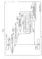
图26表示在图2的存储器112中的页面检测控制(A)112-25-1的处理流程的例子。程序在112-25-1-1开始。在步骤112-25-1-2,程序读取虚拟卷页面管理表112-15-1、检查RAID组号码112-15-1-2、以及确定容量池页面索引112-15-1-3是否存储了容量池页面信息(即,是否将容量池页面121-2分配给虚拟卷页面141-2)。在步骤112-25-1-3,程序读取虚拟卷管理表112-11-2、检查使用RAID组号码112-11-2-3、以及确定使用容量池组块号码112-11-2-4是否存储了容量池组块信息(即,是否虚拟卷114包括容量池组块121-1)。在步骤112-25-1-4,程序读取容量池组块管理表112-15-2并且检查以确定使用的容量112-15-2-3是否少于容量池组块大小(即,容量池组块121-1是否具有一个或多个空闲页面121-2)。在步骤112-25-1-5,程序改变使用RAID组号码112-11-2-3以及使用容量池组块号码112-11-2-4以移除参考。也改变前一组块号码112-15-2-5和下一组块号码112-15-2-6以在使用的组块队列索引112-11-1-6上排队使用的队列,由此将容量池组块121-1移动到使用的队列。在步骤112-25-1-6,程序改变前一组块号码112-15-2-5和下一组块号码112-15-2-6以从空闲组块队列索引112-11-1-5的空闲队列中离队。也改变使用RAID组号码112-11-2-3和使用容量池组块号码112-11-2-4来进行参考,由此除了破损的组块之外获得新的容量池组块。在步骤112-25-1-7,程序将虚拟卷页面141-2的信息存储到容量池页面管理表112-15-3,并且将容量池页面121-2的信息存储到虚拟卷页面管理表112-15-1,由此将新的容量池页面121-2从容量池组块121-1分配到虚拟卷页面141-2。在步骤112-25-1-8,程序返回容量池页面121-2地址并结束。FIG. 26 shows an example of the processing flow of the page detection control (A) 112-25-1 in the
图27表示在图2的存储器112中的页面检测控制(B)112-25-2的处理流程的例子。程序在112-25-2-1开始。在步骤112-25-2-2,程序读取虚拟卷页面管理表112-15-1、检查RAID组号码112-15-1-2、以及确定容量池页面索引112-15-1-3是否存储了容量池页面信息(即,是否将容量池页面121-2分配给虚拟卷页面141-2)。在步骤112-25-2-3,程序发现保留的容量池页面(存储格式化的数据)。在步骤112-25-2-4,程序返回容量池页面121-2的地址。程序在112-25-2-5结束。FIG. 27 shows an example of the processing flow of the page detection control (B) 112-25-2 in the
图28表示在图2的存储器112中的页面转移控制112-25-3的处理流程的例子。程序在112-25-3-1开始。在步骤112-25-3-2,程序重复该处理直到不存在属于破损的RAID组的页面(即,在破损的RAID组中的所有组块都被转移了)。在步骤112-25-3-3,程序选择除了破损的RAID组的RAID组,并且改变前一组块号码112-15-2-5和下一组块号码112-15-2-6以从空闲组块队列索引112-11-1-5的空闲队列中离队。在步骤112-25-3-4,程序调用复制控制112-22-3以将组块数据从破损的组块复制到新的组块。在步骤112-25-3-5,程序调用奇偶计算控制112-22-4来生成或恢复丢失的数据。在步骤112-25-3-6中,程序改变虚拟卷页面管理表112-15-1来参考新分配的容量池组块中的新的页面,由此改变分配信息。在步骤112-25-3-7,程序改变使用RAID组号码112-11-2-3和使用容量池组块号码112-11-2-4来移除参考,并且改变前一组块号码112-15-2-5和下一组块号码112-15-2-6以排队到使用的组块队列索引112-11-1-6上的使用的队列,由此释放破损的组块。程序在112-25-3-8结束。Fig. 28 shows an example of the processing flow of the page transfer control 112-25-3 in the
图29表示通过组块和页面复制的数据恢复的例子。图29表示两个RAID组。第一RAID组包括磁盘121a、121b、121c、121d、121e、121f、121g和121h。第二RAID组包括磁盘121i、121j、121k、121m、121n、121p、121q和121r。磁盘121c发生故障。实箭头线意味着由指针参考的对象,而虚箭头线意味着由计算参考(更详细地,由奇偶计算参考)的对象。数据恢复处理搜索使用发生故障的磁盘121c的第一RAID组中的组块(F1、F2、F3、F4),并且选择健康第二RAID组(D’1、D’2、D’3、D’4)中的未使用的组块。除了从具有组块部F3的发生故障的磁盘121c复制组块数据之外,组块数据还被从第一RAID组中的组块(F1、F2、F3、F4)复制到第二RAID组(即,磁盘121a中的F1、磁盘121f中的F2、磁盘121h中的F4被复制为磁盘121i中的F1’、磁盘121j中的F2’、以及磁盘121r中的F4’)。如虚箭头线所示,在发生故障的磁盘121c中的组块部F3的数据通过奇偶计算从其它磁盘(磁盘121a中的F1、磁盘121f中的F2、磁盘121h中的F4)恢复以在磁盘121q中形成组块部F3’。图30表示图29的数据恢复的总结和时序。Fig. 29 shows an example of data restoration by chunk and page copy. Figure 29 shows two RAID groups. The first RAID group includes
图31表示通过组块和页面复制的数据恢复的整个时序。图29和30表示一个组块的数据恢复,而图31表示多个组块的数据恢复。通过避免磁盘读/写冲突,可以优化数据恢复机制并且与并行转移处理。Fig. 31 shows the overall sequence of data restoration by chunk and page copy. Figures 29 and 30 show data recovery of one chunk, while Figure 31 shows data recovery of multiple chunks. By avoiding disk read/write conflicts, data recovery mechanisms can be optimized and processed in parallel with transfers.
在上面的例子中,在组中的硬盘驱动器的数目是8的倍数(对于具有数据条的数据的硬盘驱动器的数目M是6,对于具有数据条的奇偶数据的硬盘驱动器的数目N是2)。在从包括组中的硬盘驱动器的一个的故障的数据条之一读取数据的情况下,控制存储控制器以仅访问七个硬盘驱动器而不访问故障的硬盘驱动器。存储系统包括具有未分配的硬盘驱动器的容量池卷。从容量池卷分配数据条。响应于从另一个存储装置接收数据来进行每个数据条的分配。In the above example, the number of hard drives in the group is a multiple of 8 (the number M of hard drives with striped data is 6, and the number N of hard drives with striped parity data is 2) . In the case of reading data from one of the failed data strips including one of the hard disk drives in the group, the storage controller is controlled to access only the seven hard disk drives and not the failed hard disk drive. The storage system includes capacity pool volumes with unallocated hard drives. Allocate stripes from capacity pool volumes. Allocation of each stripe of data occurs in response to receiving data from another storage device.
第二实施例second embodiment
图32表示根据本发明的第二实施例在图1的存储子系统100中的存储器112的例子。仅讨论对图2的第一实施例的改变。在图32中,磁盘管理表112-11-3(图33)提供在用于磁盘121的物理结构管理的图2的RAID组管理表112-11-1的位置上。图32还表示可选的实施例,即虚拟卷管理表112-11-2’(图34)取代112-11-2、虚拟卷页面管理112-15-1’(图35)取代112-15-1、容量池组块管理表112-15-2’(图36)取代112-15-2、页面检测控制112-25-1’(图39)取代112-25-1以及页面转移控制112-25-3’(图40)取代112-25-3。FIG. 32 shows an example of the
图33表示在图32的存储器112中的磁盘或HDD管理表112-11-3的例子。磁盘管理表112-11-3包括以下列:表示磁盘121的ID的磁盘号码112-11-3-1、表示磁盘121的容量的磁盘容量112-11-3-4、以及表示使用的容量池信息包的列表的使用的数据包号码112-11-3-3。Fig. 33 shows an example of the disk or HDD management table 112-11-3 in the
图34表示图32的存储器112中的虚拟卷管理表112-11-2’的例子。虚拟卷管理表112-11-2’包括相同的两列(与根据第一实施例的图4的112-11-2):表示虚拟卷ID的虚拟卷号码112-11-2-1、以及表示虚拟卷的容量的虚拟卷容量112-11-2-2(“N/A”意味着虚拟卷不存在)。虚拟卷管理表112-11-2’还包括以下列:表示属于虚拟卷当前使用的容量池组块的磁盘121的ID列表的磁盘号码112-1-2’-3、以及表示属于虚拟卷当前使用的容量池组块的容量池信息包的ID列表的数据包号码112-11-2’-4。Fig. 34 shows an example of the virtual volume management table 112-11-2' in the
图35表示在图32的存储器112中的虚拟卷页面管理表112-15-1’的例子。虚拟卷页面管理表112-15-1’包括表示虚拟卷页面的顶部地址的虚拟卷页面索引112-15-1-1的列,如根据第一实施例的图5的112-15-1。而与112-15-1不同,虚拟卷页面管理表112-15-1’包括以下列:表示属于虚拟卷页面参考的容量池页面的磁盘121的ID列表的磁盘号码112-15-1’-2,以及表示属于虚拟卷页面参考的容量池页面的地址的ID列表的容量池页面索引112-15-1’-3。Fig. 35 shows an example of the virtual volume page management table 112-15-1' in the
图36表示图32的存储器112中的容量池组块管理表112-15-2’的例子。与图6的第一实施例中的表112-15-2相比,图32的容量池组块管理表112-15-2’包括以下列:表示构成容量池组块121-1的磁盘121的ID列表的磁盘或HDD号码112-15-2’-5,以及表示构成容量池组块的容量池信息包121-4的ID列表的信息包号码112-15-2’-6。Fig. 36 shows an example of the capacity pool chunk management table 112-15-2' in the
图37表示虚拟卷141及其虚拟卷管理表112-11-2’和虚拟卷页面管理表112-15-1’的例子。实箭头线意味着指针参考的对象(从虚拟卷页面管理表112-11-2’和虚拟卷页面管理表112-15-1’到容量池信息包121-4以及容量池数据条121-3),而虚箭头线意味着计算参考的对象(在虚拟卷141和管理表112-11-2和112-15-1之中以及磁盘管理表112-11-3和磁盘121之间)。虚拟卷141和虚拟卷管理表112-11-2’处于一对一的关系。虚拟卷管理表112-11-2’显示使用当前容量池信息包121-4的容量。虚拟卷页面141-2和虚拟卷页面管理表112-15-1’处于一对一的关系。如果页面被分配,虚拟卷页面管理表112-15-1’参考容量池页面121-2的片段(slice)。Fig. 37 shows an example of the
图38表示对于图37的虚拟卷141中的容量池的表参考结构的例子。实箭头线意味着指针参考的对象(从容量池组块管理表112-15-2’到容量池信息包121-4)。虚箭头线意味着计算参考的对象(在容量池页面管理表112-15-3’、容量池组块管理表112-15-2’、磁盘121、以及容量池数据条121-3之中)。磁盘121和磁盘管理表121-11-3处于一对一的关系。磁盘管理表112-11-3参考使用的和未使用的容量池信息包112-4。容量池信息包121-4和容量池组块管理表112-15-2’处于一对一的关系。容量池组块管理表112-15-2’参考虚拟卷141。容量池页面管理表112-15-3’和容量池信息包121-4处于一对多的关系。容量池页面管理表112-15-3’参考虚拟卷页面141-2。FIG. 38 shows an example of the table reference structure for the capacity pool in the
图39表示在图32的存储器112中的页面检测控制(A)112-25-1’的处理流程的例子。除了步骤112-25-1’-6(取代112-25-1-6)和112-25-1’-7(取代112-25-1-7)之外,程序执行与图26的第一实施例中的12-25-1相同的步骤。在步骤112-25-1’-6,程序加入使用的信息包号码112-11-3-3、获得新的容量池组块管理行、并且改变磁盘号码112-11-2’-3和容量池信息包号码112-11-2’-4来进行参考。在步骤112-25-1’-7,程序将虚拟卷页面141-2的信息存储到容量池页面管理表112-15-3’,以及将容量池信息包121-4信息的片段存储到虚拟卷页面管理表112-15-1’,由此将新的容量池页面分配到虚拟卷页面。Fig. 39 shows an example of the processing flow of the page detection control (A) 112-25-1' in the
图40表示在图32的存储器112中的页面转移控制112-25-3’的处理流程的例子。除了步骤112-25-3’-3(取代步骤112-25-3-3)之外,程序执行与图28的第一实施例中112-25-3相同的步骤。在步骤112-25-3’-3,程序选择除破损磁盘之外的磁盘121,加入使用的信息包号码112-11-3-3,并且获得新的容量池组块管理行。Fig. 40 shows an example of the processing flow of the page transfer control 112-25-3' in the
从上文中显而易见本发明提供了用于从例如HDD故障的存储装置故障的快速数据恢复的方法、设备和存储在计算机可读介质中的程序。另外,尽管在说明书中已经说明和描述了特定实施例,本领域普通技术人员应当理解计算用于达到相同目的的任何布置可以替换揭示的特定实施例。本揭示意欲覆盖本发明的任何以及所有适配或变化,并且需要理解在所附说明书中使用的术语不应当被理解为将本发明限制到说明书中揭示的特定实施例。相反,本发明的范围应当全部由所附权利要求来确定,应当根据建立的权利要求解释的原则以及这样的权利要求所具有的等同的完全范围来理解所附权利要求。As apparent from the above, the present invention provides a method, an apparatus and a program stored in a computer-readable medium for fast data recovery from a storage device failure such as a HDD failure. Additionally, while specific embodiments have been illustrated and described in the specification, those of ordinary skill in the art will appreciate that any arrangement, calculated to achieve the same purpose, may be substituted for the specific embodiments disclosed. This disclosure is intended to cover any and all adaptations or variations of the invention, and it is to be understood that the terms used in the accompanying specification should not be construed as limiting the invention to the specific embodiments disclosed in the specification. Rather, the scope of the invention should be determined entirely by the appended claims, which should be construed in accordance with established doctrines of claim interpretation and to the full extent of equivalents to which such claims are entitled.
Claims (20)
Applications Claiming Priority (2)
| Application Number | Priority Date | Filing Date | Title |
|---|---|---|---|
| US12/257,487 | 2008-10-24 | ||
| US12/257,487US7904749B2 (en) | 2008-10-24 | 2008-10-24 | Fast data recovery from HDD failure |
Publications (2)
| Publication Number | Publication Date |
|---|---|
| CN101727363Atrue CN101727363A (en) | 2010-06-09 |
| CN101727363B CN101727363B (en) | 2013-01-16 |
Family
ID=41509079
Family Applications (1)
| Application Number | Title | Priority Date | Filing Date |
|---|---|---|---|
| CN2009101612945AExpired - Fee RelatedCN101727363B (en) | 2008-10-24 | 2009-07-30 | Fast data recovery from HDD failure |
Country Status (4)
| Country | Link |
|---|---|
| US (4) | US7904749B2 (en) |
| EP (1) | EP2180407B1 (en) |
| JP (1) | JP5256149B2 (en) |
| CN (1) | CN101727363B (en) |
Cited By (6)
| Publication number | Priority date | Publication date | Assignee | Title |
|---|---|---|---|---|
| CN102279777A (en)* | 2011-08-18 | 2011-12-14 | 成都市华为赛门铁克科技有限公司 | Method and device for processing data redundancy and distributed storage system |
| CN107491263A (en)* | 2016-06-12 | 2017-12-19 | 北京忆恒创源科技有限公司 | A kind of data reconstruction method based on storage object |
| US12271266B2 (en) | 2020-07-13 | 2025-04-08 | Samsung Electronics Co., Ltd. | Fault resilient storage device |
| US12298853B2 (en) | 2020-05-11 | 2025-05-13 | Samsung Electronics Co., Ltd. | Systems, methods, and devices for data recovery with spare storage device and fault resilient storage device |
| US12306717B2 (en) | 2020-05-11 | 2025-05-20 | Samsung Electronics Co., Ltd. | Systems, methods, and devices for data recovery using parity space as recovery space |
| US12321236B2 (en) | 2020-05-11 | 2025-06-03 | Samsung Electronics Co., Ltd. | Systems, methods, and devices for fault resilient storage |
Families Citing this family (39)
| Publication number | Priority date | Publication date | Assignee | Title |
|---|---|---|---|---|
| US7904749B2 (en) | 2008-10-24 | 2011-03-08 | Hitachi, Ltd. | Fast data recovery from HDD failure |
| US8010835B2 (en) | 2008-11-11 | 2011-08-30 | Datadirect Networks, Inc. | Storage device realignment |
| US8307367B2 (en)* | 2009-03-05 | 2012-11-06 | International Business Machines Corporation | Smart scheduling of automatic partition migration by the use of timers |
| JP5538362B2 (en)* | 2009-03-18 | 2014-07-02 | 株式会社日立製作所 | Storage control device and virtual volume control method |
| JP5444464B2 (en) | 2010-01-14 | 2014-03-19 | 株式会社日立製作所 | Storage system |
| US8566673B2 (en)* | 2011-08-04 | 2013-10-22 | Lsi Corporation | Method for improving performance in RAID systems |
| US20130054919A1 (en)* | 2011-08-30 | 2013-02-28 | International Business Machines Corporation | Methods and physical computer storage media for transferring de-duplicated data organized in virtual volumes to a target set of physical media |
| US8775733B2 (en) | 2011-08-30 | 2014-07-08 | Hitachi, Ltd. | Distribution design for fast raid rebuild architecture based on load to limit number of redundant storage devices |
| JP5643238B2 (en)* | 2012-01-06 | 2014-12-17 | 日本電気株式会社 | Disk array control device, disk array device, and disk array control method |
| US8892833B2 (en)* | 2012-01-20 | 2014-11-18 | Netapp, Inc. | Systems, methods, and computer program products providing snapshot data replication in a distributed analytic computing system |
| JP2013178862A (en)* | 2012-02-29 | 2013-09-09 | Hitachi-Lg Data Storage Inc | Library apparatus |
| US9081668B2 (en)* | 2012-03-16 | 2015-07-14 | Marvell World Trade Ltd. | Architecture to allow efficient storage of data on NAND flash memory |
| US10157011B2 (en)* | 2012-06-25 | 2018-12-18 | International Business Machines Corporation | Temporary suspension of vault access |
| WO2014016860A1 (en) | 2012-07-23 | 2014-01-30 | Hitachi, Ltd. | Raid storage system and rebuild process |
| CN102902637B (en)* | 2012-11-19 | 2015-04-22 | 北京理工大学 | Solid-state hard disk data power-off protection method |
| JP5971354B2 (en) | 2013-01-25 | 2016-08-17 | 株式会社日立製作所 | Storage system |
| US9223655B2 (en) | 2013-07-26 | 2015-12-29 | Hitachi, Ltd. | Storage system and method for controlling storage system |
| CN104007936B (en)* | 2014-01-07 | 2017-09-29 | 华为技术有限公司 | Access the method and device of data |
| US9996573B1 (en)* | 2014-03-21 | 2018-06-12 | Amazon Technologies, Inc. | Distributed system capacity dial-up |
| WO2016018383A1 (en) | 2014-07-31 | 2016-02-04 | Hewlett-Packard Development Company | Live migration of data |
| WO2016036347A1 (en) | 2014-09-02 | 2016-03-10 | Hewlett Packard Enterprise Development Lp | Serializing access to fault tolerant memory |
| US10594442B2 (en) | 2014-10-24 | 2020-03-17 | Hewlett Packard Enterprise Development Lp | End-to-end negative acknowledgment |
| US10664369B2 (en) | 2015-01-30 | 2020-05-26 | Hewlett Packard Enterprise Development Lp | Determine failed components in fault-tolerant memory |
| WO2016122637A1 (en) | 2015-01-30 | 2016-08-04 | Hewlett Packard Enterprise Development Lp | Non-idempotent primitives in fault-tolerant memory |
| WO2016122610A1 (en) | 2015-01-30 | 2016-08-04 | Hewlett Packard Enterprise Development Lp | Preventing data corruption and single point of failure in a fault-tolerant memory |
| US9672107B1 (en)* | 2015-02-11 | 2017-06-06 | Western Digital Technologies, Inc. | Data protection for a data storage device |
| US10402261B2 (en) | 2015-03-31 | 2019-09-03 | Hewlett Packard Enterprise Development Lp | Preventing data corruption and single point of failure in fault-tolerant memory fabrics |
| US10289507B1 (en)* | 2015-10-27 | 2019-05-14 | Pavilion Data Systems, Inc. | Distributed rebuild of failed storage device |
| US9841908B1 (en) | 2016-06-30 | 2017-12-12 | Western Digital Technologies, Inc. | Declustered array of storage devices with chunk groups and support for multiple erasure schemes |
| CN107870730B (en)* | 2016-09-23 | 2020-11-20 | 伊姆西Ip控股有限责任公司 | Method and system for managing storage system |
| CN108228085A (en)* | 2016-12-21 | 2018-06-29 | 伊姆西Ip控股有限责任公司 | For managing the method and apparatus of storage system |
| US10389342B2 (en) | 2017-06-28 | 2019-08-20 | Hewlett Packard Enterprise Development Lp | Comparator |
| US10691543B2 (en) | 2017-11-14 | 2020-06-23 | International Business Machines Corporation | Machine learning to enhance redundant array of independent disks rebuilds |
| US10649867B2 (en)* | 2017-12-15 | 2020-05-12 | Western Digital Technologies, Inc. | RAID array rebuild assist from external array copy |
| WO2020257977A1 (en)* | 2019-06-24 | 2020-12-30 | Micron Technology, Inc. | Memory device with parity data system and method |
| JP7191003B2 (en) | 2019-12-17 | 2022-12-16 | 株式会社日立製作所 | Storage system and storage management method |
| JP2021189937A (en) | 2020-06-03 | 2021-12-13 | 株式会社日立製作所 | Storage system and control method of storage system |
| US11392307B2 (en) | 2020-07-16 | 2022-07-19 | Hitachi, Ltd. | Data-protection-aware capacity provisioning of shared external volume |
| JP2022175427A (en)* | 2021-05-13 | 2022-11-25 | 株式会社日立製作所 | Storage system and storage management method |
Family Cites Families (25)
| Publication number | Priority date | Publication date | Assignee | Title |
|---|---|---|---|---|
| US4092732A (en)* | 1977-05-31 | 1978-05-30 | International Business Machines Corporation | System for recovering data stored in failed memory unit |
| JP2777301B2 (en)* | 1992-01-07 | 1998-07-16 | 三菱電機株式会社 | Recording device |
| JP3181398B2 (en)* | 1992-10-06 | 2001-07-03 | 三菱電機株式会社 | Array type recording device |
| US5960169A (en)* | 1997-02-27 | 1999-09-28 | International Business Machines Corporation | Transformational raid for hierarchical storage management system |
| US6105122A (en)* | 1998-02-06 | 2000-08-15 | Ncr Corporation | I/O protocol for highly configurable multi-node processing system |
| JP2000200157A (en)* | 1999-01-08 | 2000-07-18 | Nec Corp | Disk array device and data restoration method in disk array device |
| US6775791B2 (en)* | 2001-01-26 | 2004-08-10 | Dell Products L.P. | Replaceable memory modules with parity-based data recovery |
| US6665743B2 (en)* | 2001-04-18 | 2003-12-16 | International Business Machines Corporation | Method, system, and program for initializing a storage space |
| US6934904B2 (en)* | 2001-04-30 | 2005-08-23 | Sun Microsystems, Inc. | Data integrity error handling in a redundant storage array |
| US7162600B2 (en)* | 2005-03-29 | 2007-01-09 | Hitachi, Ltd. | Data copying method and apparatus in a thin provisioned system |
| US6954824B2 (en)* | 2001-10-15 | 2005-10-11 | International Business Machines Corporation | Method, system, and program for determining a configuration of a logical array including a plurality of storage devices |
| JP4236590B2 (en)* | 2002-03-13 | 2009-03-11 | 富士通株式会社 | RAID device control device |
| US7024586B2 (en)* | 2002-06-24 | 2006-04-04 | Network Appliance, Inc. | Using file system information in raid data reconstruction and migration |
| US7032093B1 (en) | 2002-08-08 | 2006-04-18 | 3Pardata, Inc. | On-demand allocation of physical storage for virtual volumes using a zero logical disk |
| US7191304B1 (en) | 2002-09-06 | 2007-03-13 | 3Pardata, Inc. | Efficient and reliable virtual volume mapping |
| US7100089B1 (en) | 2002-09-06 | 2006-08-29 | 3Pardata, Inc. | Determining differences between snapshots |
| JP3991947B2 (en)* | 2003-07-17 | 2007-10-17 | 日本電気株式会社 | Disk array device having two types of parity and a plurality of data recovery methods |
| GB2418769B (en) | 2004-10-02 | 2009-06-17 | Hewlett Packard Development Co | Method and system for storing data |
| JP2006260446A (en)* | 2005-03-18 | 2006-09-28 | Hitachi Ltd | Disk array device |
| US7444489B2 (en) | 2005-05-13 | 2008-10-28 | 3Par, Inc. | Applications for non-disruptively moving data between logical disk regions in a data storage system |
| US7502903B2 (en) | 2005-05-13 | 2009-03-10 | 3Par, Inc. | Method and apparatus for managing data storage systems |
| JP5037881B2 (en)* | 2006-04-18 | 2012-10-03 | 株式会社日立製作所 | Storage system and control method thereof |
| US8019938B2 (en)* | 2006-12-06 | 2011-09-13 | Fusion-I0, Inc. | Apparatus, system, and method for solid-state storage as cache for high-capacity, non-volatile storage |
| US8099623B1 (en) | 2008-10-08 | 2012-01-17 | Netapp, Inc. | Efficient distributed hot sparing scheme in a parity declustered RAID organization |
| US7904749B2 (en)* | 2008-10-24 | 2011-03-08 | Hitachi, Ltd. | Fast data recovery from HDD failure |
- 2008
- 2008-10-24USUS12/257,487patent/US7904749B2/enactiveActive
- 2009
- 2009-07-10EPEP09165259.4Apatent/EP2180407B1/ennot_activeNot-in-force
- 2009-07-30CNCN2009101612945Apatent/CN101727363B/ennot_activeExpired - Fee Related
- 2009-08-31JPJP2009199344Apatent/JP5256149B2/ennot_activeExpired - Fee Related
- 2011
- 2011-02-01USUS13/018,821patent/US8234519B2/ennot_activeExpired - Fee Related
- 2012
- 2012-07-09USUS13/544,417patent/US8639969B2/enactiveActive
- 2013
- 2013-12-24USUS14/139,940patent/US9189335B2/enactiveActive
Cited By (9)
| Publication number | Priority date | Publication date | Assignee | Title |
|---|---|---|---|---|
| CN102279777A (en)* | 2011-08-18 | 2011-12-14 | 成都市华为赛门铁克科技有限公司 | Method and device for processing data redundancy and distributed storage system |
| CN102279777B (en)* | 2011-08-18 | 2014-09-03 | 华为数字技术(成都)有限公司 | Method and device for processing data redundancy and distributed storage system |
| CN107491263A (en)* | 2016-06-12 | 2017-12-19 | 北京忆恒创源科技有限公司 | A kind of data reconstruction method based on storage object |
| CN107491263B (en)* | 2016-06-12 | 2022-07-22 | 北京忆恒创源科技股份有限公司 | Data reconstruction method based on storage object |
| US12298853B2 (en) | 2020-05-11 | 2025-05-13 | Samsung Electronics Co., Ltd. | Systems, methods, and devices for data recovery with spare storage device and fault resilient storage device |
| US12306717B2 (en) | 2020-05-11 | 2025-05-20 | Samsung Electronics Co., Ltd. | Systems, methods, and devices for data recovery using parity space as recovery space |
| US12321236B2 (en) | 2020-05-11 | 2025-06-03 | Samsung Electronics Co., Ltd. | Systems, methods, and devices for fault resilient storage |
| US12271266B2 (en) | 2020-07-13 | 2025-04-08 | Samsung Electronics Co., Ltd. | Fault resilient storage device |
| US12399782B2 (en) | 2020-07-13 | 2025-08-26 | Samsung Electronics Co., Ltd. | System and device for data recovery for ephemeral storage |
Also Published As
| Publication number | Publication date |
|---|---|
| US8639969B2 (en) | 2014-01-28 |
| JP5256149B2 (en) | 2013-08-07 |
| US7904749B2 (en) | 2011-03-08 |
| EP2180407B1 (en) | 2017-04-12 |
| JP2010102695A (en) | 2010-05-06 |
| US20140115384A1 (en) | 2014-04-24 |
| US20110126083A1 (en) | 2011-05-26 |
| US9189335B2 (en) | 2015-11-17 |
| US20100107003A1 (en) | 2010-04-29 |
| US8234519B2 (en) | 2012-07-31 |
| US20130003211A1 (en) | 2013-01-03 |
| CN101727363B (en) | 2013-01-16 |
| EP2180407A3 (en) | 2011-06-22 |
| EP2180407A2 (en) | 2010-04-28 |
Similar Documents
| Publication | Publication Date | Title |
|---|---|---|
| CN101727363A (en) | Fast data recovery from HDD failure | |
| US9378093B2 (en) | Controlling data storage in an array of storage devices | |
| US8560772B1 (en) | System and method for data migration between high-performance computing architectures and data storage devices | |
| JP5427630B2 (en) | Application and tier management in a dynamic page reallocation storage system | |
| US6922752B2 (en) | Storage system using fast storage devices for storing redundant data | |
| US10346245B2 (en) | Data storage system and data storage method | |
| US8838893B1 (en) | Journaling raid system | |
| CN103064765B (en) | Data reconstruction method, device and cluster storage system | |
| EP1193600A2 (en) | Memory control apparatus and its control method | |
| US10564865B2 (en) | Lockless parity management in a distributed data storage system | |
| US20090204846A1 (en) | Automated Full Stripe Operations in a Redundant Array of Disk Drives | |
| US20140281142A1 (en) | Storage System Employing MRAM and Redundant Array of Solid State Disk | |
| US11474919B2 (en) | Method for managing multiple disks, electronic device and computer program product | |
| US9626246B1 (en) | System and method for I/O optimized data migration between high performance computing entities and a data storage supported by a de-clustered raid (DCR)architecture with vertical execution of I/O commands | |
| CN111124262A (en) | Management method, apparatus and computer readable medium for Redundant Array of Independent Disks (RAID) | |
| CN118779146B (en) | Data storage method, device, medium and product | |
| US20170220481A1 (en) | Raid Data Migration Through Stripe Swapping | |
| US20180032433A1 (en) | Storage system and data writing control method | |
| CN102164165A (en) | Management method and device for network storage system | |
| US20130246710A1 (en) | Storage system and data management method | |
| US10089227B1 (en) | Systems, devices and methods using a solid state device as a caching medium with a write cache flushing algorithm | |
| JP6730344B2 (en) | Cache device and method of controlling cache device | |
| US12039205B2 (en) | Flexible raid scheme allowing fast rebuild | |
| US8140752B2 (en) | Method of executing a background task and an array controller | |
| CN102158538A (en) | Management method and device of network storage system |
Legal Events
| Date | Code | Title | Description |
|---|---|---|---|
| C06 | Publication | ||
| PB01 | Publication | ||
| C10 | Entry into substantive examination | ||
| SE01 | Entry into force of request for substantive examination | ||
| C14 | Grant of patent or utility model | ||
| GR01 | Patent grant | ||
| CF01 | Termination of patent right due to non-payment of annual fee | Granted publication date:20130116 | |
| CF01 | Termination of patent right due to non-payment of annual fee |