CN101720207B - Devices, systems and methods for delivering orthotic material into bone - Google Patents
Devices, systems and methods for delivering orthotic material into boneDownload PDFInfo
- Publication number
- CN101720207B CN101720207BCN2008800114166ACN200880011416ACN101720207BCN 101720207 BCN101720207 BCN 101720207BCN 2008800114166 ACN2008800114166 ACN 2008800114166ACN 200880011416 ACN200880011416 ACN 200880011416ACN 101720207 BCN101720207 BCN 101720207B
- Authority
- CN
- China
- Prior art keywords
- delivery
- guide tube
- bone
- distal portion
- sleeve
- Prior art date
- Legal status (The legal status is an assumption and is not a legal conclusion. Google has not performed a legal analysis and makes no representation as to the accuracy of the status listed.)
- Expired - Fee Related
Links
Images


Classifications
- A—HUMAN NECESSITIES
- A61—MEDICAL OR VETERINARY SCIENCE; HYGIENE
- A61B—DIAGNOSIS; SURGERY; IDENTIFICATION
- A61B17/00—Surgical instruments, devices or methods
- A61B17/56—Surgical instruments or methods for treatment of bones or joints; Devices specially adapted therefor
- A61B17/58—Surgical instruments or methods for treatment of bones or joints; Devices specially adapted therefor for osteosynthesis, e.g. bone plates, screws or setting implements
- A61B17/88—Osteosynthesis instruments; Methods or means for implanting or extracting internal or external fixation devices
- A61B17/8802—Equipment for handling bone cement or other fluid fillers
- A61B17/8805—Equipment for handling bone cement or other fluid fillers for introducing fluid filler into bone or extracting it
- A61B17/8819—Equipment for handling bone cement or other fluid fillers for introducing fluid filler into bone or extracting it characterised by the introducer proximal part, e.g. cannula handle, or by parts which are inserted inside each other, e.g. stylet and cannula
- A—HUMAN NECESSITIES
- A61—MEDICAL OR VETERINARY SCIENCE; HYGIENE
- A61B—DIAGNOSIS; SURGERY; IDENTIFICATION
- A61B17/00—Surgical instruments, devices or methods
- A61B17/56—Surgical instruments or methods for treatment of bones or joints; Devices specially adapted therefor
- A61B17/58—Surgical instruments or methods for treatment of bones or joints; Devices specially adapted therefor for osteosynthesis, e.g. bone plates, screws or setting implements
- A61B17/88—Osteosynthesis instruments; Methods or means for implanting or extracting internal or external fixation devices
- A61B17/8802—Equipment for handling bone cement or other fluid fillers
- A61B17/8805—Equipment for handling bone cement or other fluid fillers for introducing fluid filler into bone or extracting it
- A61B17/8811—Equipment for handling bone cement or other fluid fillers for introducing fluid filler into bone or extracting it characterised by the introducer tip, i.e. the part inserted into or onto the bone
- A—HUMAN NECESSITIES
- A61—MEDICAL OR VETERINARY SCIENCE; HYGIENE
- A61B—DIAGNOSIS; SURGERY; IDENTIFICATION
- A61B17/00—Surgical instruments, devices or methods
- A61B17/16—Instruments for performing osteoclasis; Drills or chisels for bones; Trepans
- A61B17/1604—Chisels; Rongeurs; Punches; Stamps
- A—HUMAN NECESSITIES
- A61—MEDICAL OR VETERINARY SCIENCE; HYGIENE
- A61B—DIAGNOSIS; SURGERY; IDENTIFICATION
- A61B17/00—Surgical instruments, devices or methods
- A61B17/16—Instruments for performing osteoclasis; Drills or chisels for bones; Trepans
- A61B17/1662—Instruments for performing osteoclasis; Drills or chisels for bones; Trepans for particular parts of the body
- A61B17/1671—Instruments for performing osteoclasis; Drills or chisels for bones; Trepans for particular parts of the body for the spine
- A—HUMAN NECESSITIES
- A61—MEDICAL OR VETERINARY SCIENCE; HYGIENE
- A61B—DIAGNOSIS; SURGERY; IDENTIFICATION
- A61B17/00—Surgical instruments, devices or methods
- A61B17/34—Trocars; Puncturing needles
- A61B17/3417—Details of tips or shafts, e.g. grooves, expandable, bendable; Multiple coaxial sliding cannulas, e.g. for dilating
- A61B17/3421—Cannulas
- A—HUMAN NECESSITIES
- A61—MEDICAL OR VETERINARY SCIENCE; HYGIENE
- A61B—DIAGNOSIS; SURGERY; IDENTIFICATION
- A61B17/00—Surgical instruments, devices or methods
- A61B17/34—Trocars; Puncturing needles
- A61B17/3472—Trocars; Puncturing needles for bones, e.g. intraosseus injections
- A—HUMAN NECESSITIES
- A61—MEDICAL OR VETERINARY SCIENCE; HYGIENE
- A61B—DIAGNOSIS; SURGERY; IDENTIFICATION
- A61B17/00—Surgical instruments, devices or methods
- A61B17/00234—Surgical instruments, devices or methods for minimally invasive surgery
- A61B2017/00292—Surgical instruments, devices or methods for minimally invasive surgery mounted on or guided by flexible, e.g. catheter-like, means
- A61B2017/003—Steerable
- A61B2017/00318—Steering mechanisms
- A61B2017/00331—Steering mechanisms with preformed bends
- A—HUMAN NECESSITIES
- A61—MEDICAL OR VETERINARY SCIENCE; HYGIENE
- A61B—DIAGNOSIS; SURGERY; IDENTIFICATION
- A61B17/00—Surgical instruments, devices or methods
- A61B2017/0042—Surgical instruments, devices or methods with special provisions for gripping
- A61B2017/00455—Orientation indicators, e.g. recess on the handle
- A—HUMAN NECESSITIES
- A61—MEDICAL OR VETERINARY SCIENCE; HYGIENE
- A61B—DIAGNOSIS; SURGERY; IDENTIFICATION
- A61B17/00—Surgical instruments, devices or methods
- A61B2017/00831—Material properties
- A61B2017/00867—Material properties shape memory effect
- A—HUMAN NECESSITIES
- A61—MEDICAL OR VETERINARY SCIENCE; HYGIENE
- A61B—DIAGNOSIS; SURGERY; IDENTIFICATION
- A61B90/00—Instruments, implements or accessories specially adapted for surgery or diagnosis and not covered by any of the groups A61B1/00 - A61B50/00, e.g. for luxation treatment or for protecting wound edges
- A61B90/06—Measuring instruments not otherwise provided for
- A61B2090/062—Measuring instruments not otherwise provided for penetration depth
Landscapes
- Health & Medical Sciences (AREA)
- Life Sciences & Earth Sciences (AREA)
- Orthopedic Medicine & Surgery (AREA)
- Surgery (AREA)
- Medical Informatics (AREA)
- Engineering & Computer Science (AREA)
- Biomedical Technology (AREA)
- Heart & Thoracic Surgery (AREA)
- Nuclear Medicine, Radiotherapy & Molecular Imaging (AREA)
- Molecular Biology (AREA)
- Animal Behavior & Ethology (AREA)
- General Health & Medical Sciences (AREA)
- Public Health (AREA)
- Veterinary Medicine (AREA)
- Surgical Instruments (AREA)
- Prostheses (AREA)
Abstract
Translated fromChinese
Description
Translated fromChinese本发明是2005年11月18日申请的名称为“用于将矫正材料传递到骨头中的装置、系统和方法”的美国专利申请No.11/282,102的继续部分申请,通过参考而将其全文结合于此。This application is a continuation-in-part of U.S. Patent Application Serial No. 11/282,102, filed November 18, 2005, entitled "Apparatus, System, and Method for Delivering Orthotic Material into Bone," the entirety of which is hereby incorporated by reference combined here.
技术领域technical field
本发明涉及用于稳固骨头结构的装置和方法。更具体而言,本发明涉及用于将可矫正的稳固材料传递到骨头结构中的装置、系统和方法。The present invention relates to devices and methods for stabilizing bone structures. More specifically, the present invention relates to devices, systems and methods for delivering orthotic stabilizing material into bone structures.
背景技术Background technique
已经证明损伤或疏松的骨部位的外科手术治疗对患者(例如,具有与脊椎损伤有关的背痛的患者)来说是非常有利的。Surgical treatment of damaged or loose bony sites has proven to be very beneficial for patients (eg, patients with back pain associated with spinal injuries).
人类的骨骼系统的骨头总体上可以分类成两个形态组:“皮质”骨和“松质”骨。所有骨头的的外壁由皮质骨构成,皮质骨具有骨密质结构,其特征在于显微缩孔。松质骨或“小梁”骨形成骨头的内部组织。松质骨由互连的细长杆和板的网格构成,互连的细长杆和板的网格的术语为“小梁”。The bones of the human skeletal system can generally be classified into two morphological groups: "cortical" bone and "cancellous" bone. The outer wall of all bones is composed of cortical bone, which has a compact structure characterized by microscopic shrinkage cavities. Cancellous or "trabecular" bone forms the inner tissue of the bone. Cancellous bone is composed of a grid of interconnecting elongated rods and plates, termed "trabeculae".
在某些骨科手术过程中,通过注射用于稳固小梁的姑息(palliative)(或治疗)材料来补充松质骨。例如,脊骨中的上下椎骨可以通过注射适当、治疗材料(例如,PMMA或其它骨接合剂)而有利地稳固。在其它手术中,已经证明,例如通过经椎弓根或椎弓根接近方法将稳固材料经皮注射到脊椎压缩裂缝中有利于缓解疼痛和稳固损伤骨部位。其它骨骼的骨头(例如,股骨)可以用相似方式治疗。从任何观点来看,一般的骨头或者具体的松质骨可以通过姑息注射骨兼容材料来进行加固和稳固。During certain orthopedic procedures, cancellous bone is replenished by injection of palliative (or therapeutic) material that stabilizes the trabeculae. For example, the upper and lower vertebrae in the spine can be advantageously stabilized by injection of an appropriate, therapeutic material (eg, PMMA or other bone cement). In other procedures, percutaneous injection of stabilizing materials into spinal compression fractures, eg, via a transpedicular or pedicle approach, has proven beneficial for pain relief and stabilization of injured bony sites. Bones of other bones (eg, the femur) can be treated in a similar manner. From any point of view, bone in general or cancellous bone in particular can be reinforced and stabilized by palliative injection of osteocompatible materials.
用于传递骨稳固材料的传统方法必须使用钻(或者切)穿皮质骨以获得到松质骨部位的通路的直通路装置或套管。骨稳固材料然后被驱动通过套管以填充骨部位处的松质骨部分。为了最小化手术的创伤,套管通常是直径小的针。Traditional methods for delivering bone stabilizing materials necessitate the use of straight access devices or cannulas that drill (or cut) through the cortical bone to gain access to the cancellous bone site. The bone stabilizing material is then driven through the cannula to fill the cancellous bone portion at the bony site. To minimize surgical trauma, the cannula is usually a small diameter needle.
在上述的情况下,因为针管与松质骨和气体软组织结构接触,存在下面最初插入的针管可能穿刺或刺破修复的其它组织和/或骨量(在远离插入部位的位置)的内在危险。因此,在经皮椎体成形术过程中,需要进行细心照顾,以避免刺破、穿刺或者使得脊椎主体破裂。在其它内部骨头修复手术中提出了类似的后插入穿刺忧虑。沿着这些相同的路线,为了最小化完成手术的创伤和时间,期望仅进行单骨部位插入。不幸的是,对于许多手术而言,使用传统直针管不能够完全到达所讨论的外科手术部位。例如,使用椎体成形术,内部脊椎主体的封闭特性经常需要在不同脊椎接近位置使用直针管的两次或更多次插入(“双侧”技术)。期望提供用于传递骨稳固材料的系统,其可以更容易满足特殊传递部位的解剖要求,例如,能够促进经单侧椎体成形术的系统。In the cases described above, because the needle cannula is in contact with cancellous bone and gaseous soft tissue structures, there is an inherent risk that the underlying initially inserted needle can puncture or puncture other tissue and/or bone mass of the repair (at a location remote from the insertion site). Therefore, during percutaneous vertebroplasty, careful care is required to avoid puncturing, puncturing, or fracturing the main body of the spine. Similar post-insertion puncture concerns are raised in other internal bone repair procedures. Along these same lines, in order to minimize the trauma and time to complete the procedure, it is desirable to perform only a single bone site insertion. Unfortunately, for many procedures, the surgical site in question cannot be fully reached using conventional straight needle cannula. For example, with vertebroplasty, the closed nature of the inner vertebral body often requires two or more insertions using straight needle cannula at different vertebral access locations ("bilateral" technique). It would be desirable to provide systems for the delivery of bone stabilizing materials that can more easily meet the anatomical requirements of a particular delivery site, eg, systems that can facilitate transunilateral vertebroplasty.
库克医疗公司所销售的OSTEO-RX(TM)产品线下的器械利用弯针传递作为椎体成形术或类似手术的部件的骨稳固材料。据称,弯针提高外科医生定位并将稳固材料注射在期望部位(site)的能力。类似于传统直针管,弯针通过最远端尖部的单个轴向开口分配矫正材料。但是,弯针与外套管结合使用,外套管一般辅助建立到骨部位的通路以及便于针以期望方式经皮传递到(骨头内的)传递部位。更具体而言,外套管首先获得到骨部位的通路,接着针通过外套管的进行远端滑动。一旦针尖向远侧延伸到外套管的末端,则针尖相对于骨部位暴露。为了避免当将针的远端尖部插入骨部位中时穿刺和由此潜在损伤组织,需要将另外的线部件沿轴向布置在针内并且远离远端尖部延伸。内线“保护”组织或其它身体组织免于在定位尖部时创伤接触针的远端尖部。在通过针灌输骨稳固材料之前必须移除同轴线。此外,针可以仅通过针的远端尖部处的轴向开口分配稳固材料,这也许妨碍外科医生灌输所有期望区域和/或需要将针尖“后退”远离期望传递部位的额外手术步骤。另外,因为针尖(以及由此轴向开口)很可能在或者面对待修复的骨缺损(例如,脊椎主体中的裂缝),稳固材料可以直接注射在缺损处,这产生稳固材料强制前进通过缺损或从缺损向外前进的明显可能性。这显然是不期望的。在经皮锥体成形术的上下文中描述的上述问题和忧虑也在类似的其它骨部位处的外科手术中产生。Devices under the OSTEO-RX(TM) product line sold by Cook Medical utilize curved needles to deliver bone-stabilizing material as part of vertebroplasty or similar procedures. The curved needle is said to improve the surgeon's ability to position and inject the stabilizing material at the desired site. Similar to traditional straight needle cannula, the curved needle dispenses orthodontic material through a single axial opening at the most distal tip. However, the curved needle is used in conjunction with an overtube which generally aids in establishing access to the bony site as well as facilitates percutaneous delivery of the needle to the delivery site (intra-bone) in the desired manner. More specifically, the overtube first gains access to the bony site, followed by distal sliding of the needle through the overtube. Once the needle tip is extended distally to the end of the outer cannula, the needle tip is exposed relative to the bony site. In order to avoid puncturing and thereby potentially damaging tissue when the distal tip of the needle is inserted into a bone site, it is necessary to arrange an additional wire component axially within the needle and extending away from the distal tip. The inner wire "protects" tissue or other bodily tissue from traumatic contact with the distal tip of the needle when the tip is positioned. The coaxial wire must be removed prior to infusing the bone stabilizing material through the needle. Furthermore, the needle may only dispense the stabilizing material through the axial opening at the distal tip of the needle, which may prevent the surgeon from infusing all desired areas and/or require an additional surgical step of "backing" the needle tip away from the desired delivery site. Additionally, because the needle tip (and thus the axial opening) is likely to be at or facing the bony defect to be repaired (e.g., a crack in the vertebral body), the stabilizing material can be injected directly at the defect, which results in forced advancement of the stabilizing material through the defect or Clear possibility of progressing outward from the defect. This is obviously not expected. The problems and concerns described above in the context of percutaneous coneplasty also arise in similar surgical procedures at other bony sites.
已经证明,将姑息材料注射到损失或疏松的骨部位对患者极其有利。但是,已知的通路或灌输技术使得多针棒和/或危险穿刺骨头或组织成为必要。因此,对用于将稳固材料传递到损失或疏松的骨部位的改进装置和系统存在需求。Injection of palliative materials into sites of lost or loose bone has proven to be extremely beneficial to patients. However, known access or infusion techniques necessitate multiple needle sticks and/or dangerous punctures of bone or tissue. Accordingly, there is a need for improved devices and systems for delivering stabilizing material to lost or loose bone sites.
发明内容Contents of the invention
根据本发明公开的原理所获得的优点包括在骨内手术过程中在不需要额外部件(诸如单独的线)提供非创伤的传递套管、最小化穿刺组织或刺破骨头或组织的钝的远端部。其它优点涉及邻近钝的远端部限定至少一个侧孔,其中,孔允许在骨头内的部位沿径向灌输矫正材料,即使在远端部与骨头和/或组织接触的情况下。因此,姑息骨手术能够在缩短的手术室时间以及外科设备更少靠近骨部位的情况下完成。例如,容易完成经单侧椎体成形术。此外,事实上可以接近外科部位内的任何区域。另外,在不用担心后续传递的材料会强迫前进到或穿过解剖特征的情况下,传递套管的远端部可以放置成尽可能根据需要靠近外科部位的具体解剖特征(例如,裂缝)。Advantages obtained in accordance with the principles disclosed in the present invention include providing an atraumatic delivery sheath without the need for additional components (such as separate wires), minimizing blunt distal implants that puncture tissue or puncture bone or tissue during intraosseous procedures. Ends. Other advantages relate to defining at least one side hole adjacent the blunt distal portion, wherein the hole allows for radial infusion of corrective material at a site within the bone even if the distal portion is in contact with bone and/or tissue. As a result, palliative bone surgery can be accomplished with reduced operating room time and with less proximity of surgical equipment to the bony site. For example, transunilateral vertebroplasty is easily accomplished. Furthermore, virtually any area within the surgical site can be accessed. Additionally, the distal end of the delivery cannula can be placed as close as desired to specific anatomical features (eg, fissures) at the surgical site without concern that subsequently delivered material will be forced into or through the anatomical feature.
本发明的一些方面涉及用于将矫正材料传递到骨头中的传递套管装置。该装置包括传递套管和形成流体端口的集线器。传递套管限定近端部、可变形段、远端部、腔以及至少一个侧孔。近端沿轴向对腔开口。可变形段形成与近端部相对并且终止于沿轴向封闭的远端部。此外,远端部具有钝的尖部。腔从近端部延伸并与侧孔流体连接。在此方面,侧孔邻近远端部形成并且在近侧与远端部间隔开。最后,可变形段形成沿纵向延伸的曲形形状,并且具有形状记忆特性。在此构造的情况下,可变形段可以被压迫成基本直的形状并且在移除力时自然恢复到曲形形状。集线器流体耦合到传递套管的近端部。在此构造的情况下,在使用过程中,远端部在插入骨内的传递部位中时由于钝的尖部而不损伤或穿刺组织。此外,侧孔提供无论远端部是否射入体材料而将注射矫正材料的能力,并且获得更彻底的分配。Some aspects of the invention relate to delivery cannula devices for delivering orthotic material into bone. The device includes a transfer cannula and a hub forming a fluid port. The delivery sheath defines a proximal portion, a deformable section, a distal portion, a lumen, and at least one side hole. The proximal end is axially open to the cavity. A deformable section is formed opposite the proximal portion and terminates in an axially closed distal portion. Furthermore, the distal portion has a blunt tip. A lumen extends from the proximal end and is in fluid communication with the side port. In this aspect, the side hole is formed adjacent to and proximally spaced from the distal portion. Finally, the deformable section forms a longitudinally extending curved shape and has shape memory properties. With this configuration, the deformable segment can be compressed into a substantially straight shape and naturally return to a curved shape when the force is removed. The hub is fluidly coupled to the proximal end of the delivery sheath. With this configuration, during use, the distal portion does not damage or puncture tissue due to the blunt tip when inserted into the delivery site within the bone. In addition, the side holes provide the ability to inject the corrective material regardless of whether the distal portion injects body material, and achieve a more thorough dispensing.
本发明的其它方面涉及一种骨内矫正材料传递系统,其用于将矫正材料传递到骨头内的传递部位,矫正材料诸如骨接合剂。该系统包括如上的传递套管和集线器以及导向管。传递套管和导向管的尺寸使得传递套管在导向管内可滑动。在此方面,可变形段被构造成当插入到套管内时变形成基本直的形状并且当远离导向管延伸以传递矫正材料时恢复成曲形形状。在此实施例中,导向管和传递套管的尺寸适于形成椎体成形术手术。Other aspects of the invention relate to an intraosseous orthotic material delivery system for delivering orthotic material, such as bone cement, to a delivery site in bone. The system includes the transfer cannula and hub and guide tube as above. The transfer sleeve and guide tube are sized such that the transfer sleeve is slidable within the guide tube. In this aspect, the deformable segment is configured to deform into a substantially straight shape when inserted into the cannula and return to a curved shape when extended away from the guide tube to deliver the orthotic material. In this embodiment, the guide tube and delivery sheath are sized to form a vertebroplasty procedure.
本发明的其它方面涉及稳固人类患者的骨结构的方法。此方法包括提供如上的传递套管。将导向管的远端尖部定位在骨结构内。传递套管插入导向管内。在此方面,可变形段在导向管内变形成基本直的形状。传递套管在远端相对于导向管前进,使得远端部和传递套管的至少一部分可变形段远离导向管的远端尖部突出。在此方面,可变形段中远离导向管的远端尖部的部分自然恢复到曲形形状。传递套管的远端部邻近骨结构内的期望传递部位定位。将矫正材料注射到腔中。注射的矫正材料通过侧孔传递到传递部位。一旦传递,矫正材料允许固化,以稳固骨结构。在一个实施例中,该方法还包括相对于导向管旋转传递套管,以改变侧孔的空间位置,由此提供在不同平面注射矫正材料的能力。Other aspects of the invention relate to methods of stabilizing the bone structure of a human patient. The method includes providing a delivery sheath as above. Position the distal tip of the guide tube within the bony structure. The transfer cannula is inserted into the guide tube. In this aspect, the deformable section is deformed into a substantially straight shape within the guide tube. The delivery sheath is advanced distally relative to the guide tube such that the distal portion and at least a portion of the deformable section of the delivery sheath protrude away from the distal tip of the guide tube. In this regard, the portion of the deformable section remote from the distal tip of the guide tube naturally reverts to the curved shape. The distal end of the delivery sheath is positioned adjacent a desired delivery site within the bony structure. Corrective material is injected into the cavity. The injected orthodontic material is delivered to the delivery site through the side hole. Once delivered, the orthotic material is allowed to cure to stabilize the bone structure. In one embodiment, the method further includes rotating the transfer sleeve relative to the guide tube to change the spatial location of the side holes, thereby providing the ability to inject the corrective material in different planes.
本发明的又一方面涉及将矫正材料注射到骨结构内的传递部位的方法。该方法包括提供传递套管的步骤,该传递套管具有开口、近端部、与近端部相对并具有远端部的可变形段以及从近端部延伸的腔。可变形段具有形状记忆特性,并且沿纵向延伸自然呈现曲形形状。该方法还包括将导向管的远端尖部定位在骨结构内的步骤。该方法还包括将所述传递套管插入所述导向管的步骤,其中可变形段在导向管内变形成基本直的形状,并且在远端前进传递套管使得远端部和至少一部分可变形段远离远端尖部突出。可变形段中远离导向管的远端尖部的部分然后自然恢复到曲形形状。该方法还包括操作传递套管使得至少一部分可变形段在骨结构内的软体组织中产生一个或多个空洞的步骤。该方法还包括将矫正材料传递到传递部位的步骤,其中,矫正材料传递到软体组织中由可变形段所产生的一个或多个空洞。Yet another aspect of the invention relates to a method of injecting an orthotic material into a delivery site within a bony structure. The method includes the step of providing a delivery sheath having an opening, a proximal end, a deformable section opposite the proximal end and having a distal end, and a lumen extending from the proximal end. The deformable segment has shape memory properties and naturally assumes a curved shape extending longitudinally. The method also includes the step of positioning the distal tip of the guide tube within the bony structure. The method also includes the steps of inserting the delivery sheath into the guide tube, wherein the deformable section deforms into a substantially straight shape within the guide tube, and distally advancing the delivery sheath such that the distal end and at least a portion of the deformable section Protrudes away from the distal tip. The portion of the deformable section remote from the distal tip of the guide tube then naturally returns to the curved shape. The method also includes the step of manipulating the delivery sheath such that at least a portion of the deformable segment creates one or more cavities in soft tissue within the bony structure. The method also includes the step of delivering the corrective material to the delivery site, wherein the corrective material is delivered to the one or more cavities in the soft body tissue created by the deformable segments.
本发明的又一方面涉及将矫正材料注射到骨结构内的方法。该方法包括提供传递套管的步骤,该传递套管具有开口、近端部、与近端部相对并具有远端部的可变形段以及从近端部延伸的腔。可变形段具有形状记忆特性,并且沿纵向延伸自然呈现曲形形状。在此方法中,将导向管的远端尖部定位在骨结构内。将传递套管插入导向管内,其特征在于,可变形段在导向管内变形成基本直的形状。在远端前进传递套管,使得远端部和至少一部分可变形段远离远端尖部突出,其特征在于,可变形段中远离远端尖部的部分自然恢复到曲形形状。将远端部向远侧定位在邻近传递部位内的第一区域。然后将矫正材料传递到传递部位内的第一区域。远端部然后邻近传递部位内的第二区域定位并且矫正材料传递到传递部位内的第二区域。Yet another aspect of the invention relates to a method of injecting an orthotic material into a bony structure. The method includes the step of providing a delivery sheath having an opening, a proximal end, a deformable section opposite the proximal end and having a distal end, and a lumen extending from the proximal end. The deformable segment has shape memory properties and naturally assumes a curved shape extending longitudinally. In this method, the distal tip of the guide tube is positioned within the bony structure. The transfer sleeve is inserted into the guide tube, characterized in that the deformable section is deformed into a substantially straight shape within the guide tube. The delivery sheath is distally advanced such that the distal portion and at least a portion of the deformable section protrude away from the distal tip, wherein a portion of the deformable section distal from the distal tip naturally returns to the curved shape. The distal end is positioned distally adjacent to the first region within the delivery site. The orthotic material is then delivered to the first region within the delivery site. The distal portion is then positioned adjacent to the second region within the transfer site and the orthotic material is transferred to the second region within the transfer site.
本发明的又一方面涉及一种用于将矫正材料传递到骨头中的套管装置,其作为矫正材料传递系统的一部分,矫正材料诸如骨接合剂。该装置包括预载有骨接合剂的传递套管,该传递套管限定开口、近端部、与近端部相对并且终止于封闭远端部的可变形段。该装置包括从近端部延伸的腔。该装置还包括邻近远端部形成并且在近侧与远端部间隔开的至少一个侧孔,侧孔与腔流体连接,其中,可变形段形成沿纵向延伸的曲形形状,并且具有形状记忆特性,使得可变形段被构造成在受力时沿纵向呈现基本直的形式并且在移除力时自然恢复到曲形形状。Yet another aspect of the invention relates to a cannula device for delivering an orthodontic material, such as bone cement, into bone as part of an orthodontic material delivery system. The device includes a delivery sheath preloaded with bone cement defining an opening, a proximal portion, a deformable section opposite the proximal portion and terminating in a closed distal portion. The device includes a lumen extending from the proximal end. The device also includes at least one side hole formed adjacent to the distal portion and spaced proximally from the distal portion, the side hole being fluidly connected to the lumen, wherein the deformable segment forms a longitudinally extending curved shape and has a shape memory properties such that the deformable segment is configured to assume a substantially straight form longitudinally when a force is applied and to naturally return to a curved shape when the force is removed.
本发明的又一方面涉及一种骨内矫正材料传递系统,其用于将矫正材料传递到骨头内的传递部位,矫正材料诸如骨接合剂。该系统包括传递套管,该传递套管具有开口、近端部、与近端部相对并具有远端部的可变形段以及从近端部延伸的腔,其中,可变形段终止于远端部,其中,可变形段具有形状记忆特性,并且沿纵向延伸自然呈现曲形形状。该系统还包括导向管,导向管的内径大于传递套管的外径,并且具有开口远端尖部,其中,可变形段被构造成可变形成基本直的形状,使得传递套管在导向管内可滑动,并且当远离远端尖部延伸以通过远端部将矫正材料传递到植入部位内时,可变形段自然恢复到曲形形状,并且其中,传递套管在导向管内可以平稳滑动。Yet another aspect of the invention relates to an intraosseous orthodontic material delivery system for delivering orthodontic material, such as bone cement, to a delivery site in bone. The system includes a delivery sheath having an opening, a proximal end, a deformable segment opposite the proximal end and having a distal end, and a lumen extending from the proximal end, wherein the deformable segment terminates at the distal end part, wherein the deformable segment has shape memory properties and naturally assumes a curved shape along the longitudinal extension. The system also includes a guide tube having an inner diameter greater than the outer diameter of the delivery sheath and having an open distal tip, wherein the deformable section is configured to deform into a substantially straight shape such that the delivery sheath is within the guide tube The deformable section naturally returns to a curved shape when extended away from the distal tip to deliver orthotic material through the distal portion into the implant site, and wherein the delivery sleeve slides smoothly within the guide tube.
本发明的又一方面涉及稳固脊椎主体的矫正材料结构。该结构包括第一矫正材料沉积,其邻近于脊椎主体的终板,用于为脊椎主体的第一终板提供支撑。该结构包括第二矫正材料沉积,其邻近于脊椎主体的终板,用于为脊椎主体的第二终板提供支撑。该结构还包括位于第一矫正材料沉积和第二矫正材料沉积之间的矫正材料柱,其为脊椎主体提供支撑。Yet another aspect of the present invention relates to an orthodontic material structure for stabilizing a vertebral body. The structure includes a first orthotic material deposit adjacent to an endplate of the vertebral body for providing support to the first endplate of the vertebral body. The structure includes a second corrective material deposit adjacent to the endplate of the vertebral body for providing support to the second endplate of the vertebral body. The structure also includes a post of orthotic material positioned between the first and second orthotic material deposits that provides support to the vertebral body.
附图说明Description of drawings
包括附图以进一步提供对本发明的理解,并且附图包括在本说明书中并且作为说明书的一部分。容易意识到本发明的其它实施例以及本发明的许多预期优点,因为它们通过参考下面详细说明可以更好地理解。附图的元件之间不是依比例绘制的。相似的附图标记表示对应的相似部件。The accompanying drawings are included to provide a further understanding of the invention, and are incorporated in and constitute a part of this specification. Other embodiments of the invention, as well as the many anticipated advantages of the invention, will readily become apparent as they are better understood by reference to the following detailed description. Elements of the drawings are not drawn to scale. Like reference numerals designate corresponding like parts.
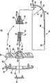
图1图示根据本发明原理的骨内矫正材料传递系统的部件;Figure 1 illustrates components of an intraosseous orthodontic material delivery system in accordance with the principles of the present invention;
图2A是图1的系统的传递套管装置部件的剖示分解图;Figure 2A is a cutaway exploded view of components of the transfer cannula device of the system of Figure 1;
图2B是图2A装置的传递套管和集线器部分的正视图;Figure 2B is a front view of the delivery sleeve and hub portion of the device of Figure 2A;
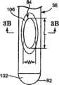
图3A是图2A的传递套管的远端部分的放大平面图;Figure 3A is an enlarged plan view of the distal portion of the delivery sheath of Figure 2A;
图3B是图3A的传递套管的剖视图;Figure 3B is a cross-sectional view of the delivery sleeve of Figure 3A;
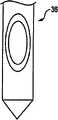
图3C是图2A中的传递套管的远端部分根据本发明另一优选实施例的放大平面图;3C is an enlarged plan view of the distal portion of the delivery sheath in FIG. 2A according to another preferred embodiment of the present invention;
图3D是图2A中的传递套管的远端部分根据本发明另一优选实施例的放大平面图;3D is an enlarged plan view of the distal portion of the delivery sheath in FIG. 2A according to another preferred embodiment of the present invention;
图3E是图2A的传递套管的远端部分根据本发明另一优选实施例的放大平面图;3E is an enlarged plan view of the distal portion of the delivery sheath of FIG. 2A according to another preferred embodiment of the present invention;
图4是图2A的传递套管装置最后组装后的剖视图;Fig. 4 is a cross-sectional view of the transfer cannula device of Fig. 2A after final assembly;
图5是根据本发明原理的可选传递套管装置的侧视图;Figure 5 is a side view of an alternative transfer cannula device in accordance with the principles of the present invention;
图5A是根据本发明原理的可选传递套管装置的侧视图;Figure 5A is a side view of an alternative delivery cannula device in accordance with the principles of the present invention;
图5B是根据本发明原理的可选传递套管装置的侧视图;Figure 5B is a side view of an alternative delivery cannula device in accordance with the principles of the present invention;
图6A根据本发明原理用于姑息骨手术的骨内矫正材料传递系统的简化图;Figure 6A is a simplified diagram of an intraosseous corrective material delivery system for palliative bone surgery in accordance with the principles of the present invention;
图6B是图6A的系统中一部分的剖视图;Figure 6B is a cross-sectional view of a portion of the system of Figure 6A;
图6C图示图6A的系统所进行的手术的最后阶段;Figure 6C illustrates the final stage of the procedure performed by the system of Figure 6A;
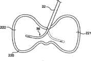
图6D是6A的系统中一部分与脊椎主体的横截面图,其图示矫正材料的注射;Figure 6D is a cross-sectional view of a portion of the system of 6A with a vertebral body illustrating injection of corrective material;
图6E是脊椎主体的横截面图,其图示根据本发明原理可用的各种锥体成形术接近位置;Figure 6E is a cross-sectional view of a vertebral body illustrating various pyramidal plasty access locations that may be used in accordance with the principles of the present invention;
图7A和7B是脊椎主体的简化前位图,其图示根据本发明原理的系统的使用;7A and 7B are simplified anterior views of a vertebral body illustrating use of the system in accordance with the principles of the present invention;
图8A和8B是脊椎主体的简化侧面图,其图示根据本发明原理的系统的使用;8A and 8B are simplified side views of a vertebral body illustrating the use of the system in accordance with the principles of the present invention;
图9是脊椎主体的简化侧面图,其图示根据本发明原理的系统的使用;Figure 9 is a simplified side view of a vertebral body illustrating the use of the system in accordance with the principles of the present invention;
图10是脊椎主体的简化侧面图,其图示根据本发明原理的系统的使用;Figure 10 is a simplified side view of a vertebral body illustrating the use of the system in accordance with the principles of the present invention;
图11A-11C是脊椎主体的简化前位图,其图示根据本发明原理的系统的使用;以及11A-11C are simplified anterior views of the vertebral body illustrating use of the system in accordance with the principles of the present invention; and
图12是骶骨的简化前位图,其图示根据本发明原理的系统的使用。Figure 12 is a simplified anterior view of the sacrum illustrating use of the system in accordance with the principles of the present invention.
具体实施方式Detailed ways
图1图示根据本发明原理的骨内矫正材料传递系统20的部件。系统20包括外导管22和传递套管26(总附图标记)。下面提供各种部件的详细描述。但是,总体而言,传递套管装置26中的一部分的尺寸适于可滑动布置在导管22内,导管22另外适于用来形成和/或定位骨头内部的期望传递部位。一旦定位,使用传递套管装置26将可矫正骨稳固材料注射到传递部位。系统20可以用于许多不同手术,例如包括:锥体成形术或其中矫正材料被传递到骨头内部位以及从骨头内部位取出后抽出材料的其它骨强化手术。FIG. 1 illustrates components of an intraosseous orthodontic material delivery system 20 in accordance with the principles of the present invention. System 20 includes
系统20,具体而言,传递套管装置26对将传递骨接合剂材料形式的矫正材料是非常有用的。在可以由这里描述的本发明系统/装置所传递的物质的环境下,短语“矫正材料”意欲指的是具有流态或可流动状态或相以及硬化、固态或固化状态或相的材料(例如化合物或聚合物等)。矫正材料包括但不限于可注射的聚甲基丙烯酸甲酯(PMMA)骨接合剂,其具有可流动状态,其中其可以被套管传递(例如,注射)到部位并且接着固化成硬化接合剂。可以使用其它材料(诸如,亚磷酸氢钙、骨增长材料、抗生素、蛋白质等),来代替或增加到PMMA(但是不影响具有可流动状态和硬化、固态或固化状态的得到的处方的重叠特性)。基于填充物植入材料,这允许主体再吸收接合剂或改善临床结果。在此情况下以及在一个实施例中,系统20还包括流体耦合到传递套管装置26的矫正材料的源(未示出)。The system 20, and in particular the
在上述情况下下,外导管22一般能够将传递套管装置26通路到感兴趣的骨部位,并且由此可以呈现各种形式。但是,总体而言,导向管22的尺寸适于可滑动接收传递套管装置26的一部分,终止于开口的远端尖部28。远端尖部28还可以适于便利于骨组织的穿刺,诸如当使用导向管22在骨头内形成传递部位。为了促进导向管22和传递套管装置26中在使用过程中可滑动地插入到导向管22内的一部分之间的期望界面,在一个实施例中,导向管22的内径表面非常光滑,达到无光泽或镜面光洁度(例如,约0-16的均方值(RMS)范围)。在另一个优选实施例中,导向管的内径表面或传递套管36的外径表面可以涂覆有特氟隆,以促进导向管22和传递管装置26中在使用过程中可以滑动插入导向管22内的一部分之间的期望光滑界面。在导向管22和传递套管装置26之间也可以使用特氟隆套筒。此外,传递套管36的外径表面可以抛光以非常光滑到无光泽或镜面光洁度(即,约0-16的RMS范围)。无论如何,在一些实施例中,导向管22在其近端可以附装到用于增强外科医生操作系统20的能力的操作柄30。可选地,可以取消操作柄30。In the cases described above, the
传递套管装置26在图2A中更详细地示出,其总体上包括操作柄组件32(总附图标记)、集线器34和传递套管36。在操作柄组件32保持集线器34/传递套管36组合的情况下,集线器端口34形成流体端口并且与传递套管36流体连接。如下更详细地描述,传递套管36的尺寸适于同轴可滑动接收于导向管22(图1)内,并且适于通过集线器34传递注射在其中的矫正材料。The
操作柄组件32在一个实施例中包括操作柄40和保持器42。操作柄40适于接收集线器34,而保持器42将集线器34(由此将传递套管36)固定到操作柄40上。The handle assembly 32 includes a
在一个实施例中,操作柄40包括第一部分44和第二部分46。第一部分44适于将组件滑入配合到第二部分46,诸如通过互补(complimentary)的环形突起48和凹槽50。无论如何,第一部分44形成有从其外表面54向内延伸的中心通道52。In one embodiment, the
第二部分46限定内部孔56,在操作柄40最后组装的情况下,内部孔56于中心通道52对准。孔56可以呈现各种形式,其尺寸适于以嵌套方式接收集线器34。操作柄40和集线器34之间的嵌套界面优选地适于使得集线器34在最后组装情况下不能相对于操作柄40旋转(即,集线器34/操作柄40界面抵抗施加在任一个部件上的扭矩,使得操作柄40的旋转运动导致集线器34/传递套管36的相同旋转,即使在传递套管36插入封闭的外科手术部位内时)。因此,在一个实施例中,孔56和集线器34(如下所述)的横截面具有对应的非对称或非圆形形状。相对于图2A的纵向剖视图,孔56的非圆形形状特征在于,孔56由侧壁58所限定,该侧壁58具有与如下更详细描述的集线器34的形状对应的肩部60。可选地,侧壁58可以呈现各种其它构造。无论如何,在一个实施例中,第二部分46形成有外螺纹62。The
保持器42被构造成将集线器34/传递套管36固定到操作柄40,并且形成有限定近端部分66和远端部分68的中心开口64。近端部分66形成有直径稍微大于集线器34的中心开口64,并且具有尺寸适于和操作柄40的外螺纹62进行螺纹接合的内螺纹70。远端部分68形成有开口64,其直径接近传递套管36的外径,以在操作柄组件32和集线器34/传递套管36之间提供更刚性连接。可选地,操作柄组件32可以呈现各种其它形式,并且在一些实施例中可以完全取消。The
在一个实施例中,集线器34为传统流体端口设计,并且限定流体通道71以及位于其近端部74上的外螺纹72。在一个实施例中,螺纹72是包括5毫米导程的双线右旋鲁尔(Luer)螺纹,但是其它螺纹结构和导程尺寸也是可以接受的。无论如何,如上所述,在一个实施例中,集线器34被构造成在最终组装后的情况下可相对于操作柄组件32旋转“锁死”。因此,在一个实施例中,集线器34的主体形成大致圆柱表面76,该圆柱表面76的一部分在区域78中变平,如图2B所示。变平区域78的尺寸和形状对应于设置于操作柄40(图2A)上的孔侧壁58(图2A)。In one embodiment, the
在一个实施例中,集线器34由可消毒的聚合材料形成。通过示例,集线器34可以由polylac 717C丙烯腈-丁二烯-苯乙烯(ABS)共聚物形成,但是其它可消毒的聚合物和/或共聚物也是可以接受的。In one embodiment,
在另一个优选实施例中,可移除的盖38适于附装到操作柄组件32的第一部分44并且盖住集线器34的流体通道71。当传递套管36插入到导向管22中时,血或其它流体可以在传递套管36内行进并且通过集线器34的流体通道71离开。在传递套管36引入到导向管22时,可移除的盖38可以附装到操作柄组件32。在将传递套管36插入到期望位置后,移除可移除的盖38,以允许到集线器34的通路。In another preferred embodiment, a
返回图2A,传递套管36限定近端部80和远端部82,并且邻近远端部80形成有与内腔86流体连通的一个或多个侧孔84。另外,传递套管36包括限定预设曲形部或弯曲部90的可变形段88(总附图标记)。如下所述,可变形段88,具体而言弯曲部90包括远端部82或者从远端部82延伸,并且具有形状记忆属性,由此可变形段88可以从弯曲形状(图2A中所示)受迫到基本直的形状,并且在移除力的情况下自然恢复到弯曲形状。Returning to FIG. 2A ,
近端部80沿轴向朝腔86开口。相反,远端部82沿轴向密闭腔86(即,材料不能相对于腔86的轴线沿轴向排出远端部)。也就是说,腔86中的材料能够在其远端沿轴向方式推动。此外,远端部82限定或包括钝的尖部100。例如,在一个实施例中,钝的尖部100限定半球形表面,但是其它钝(曲形或曲线)形状或外形也是可以接受的。钝的尖部表面100适于提供非创伤表面,用于接近(accessing)、接触和针探骨头或组织,同时最小化组织的刺破和/或穿刺或对骨头损失的危险。为了增强期望的柔软性,与传递套管36的其它部分相比,钝的尖部100可以具有不同厚度,诸如通过烧结远端部82,以形成钝的尖部100(当传递套管36最初设置为连续管时)。可选地,钝的尖部100可以与传递套管36的其余部分分开形成,并且随后附装到传递套管36,以形成远端部82(例如,传递套管36可以由硬化材料形成的第一管状体以及由较软材料形成的第二固态体,第二固态体附装(例如,焊接)到管状体以形成远端部82/钝的尖部100)。
参照图2A和2B,侧孔84邻近远端部82形成,其延伸通过传递套管36的侧壁厚。在一个实施例中,设置单个孔84,并且孔84定位成与弯曲部90的方向相反。换而言之,相对于图2A的纵向剖视图,弯曲部90的方向用于形成传递套管36,以限定内弯侧102和外弯侧104。在这些标号的情况下,侧孔84沿外弯侧104形成并且相对于外弯侧104开口。已经令人惊讶地发现,通过将侧孔84定位成与弯曲部90“相反”,使用者会感到对将矫正材料从传递套管36分配方向的控制提高。可选地,可以设置更大数量的侧孔84,其可以或者可以不沿圆周对准,并且可以或可以不沿传递套管36的外弯侧104定位。总体而言,侧孔84从远端部82偏移至少距离D1。在一个实施例中,距离D1在0.05英寸和0.5英寸之间,并且优选地,距离D1在0.1英寸和0.25英寸之间。在此构造下,即使当钝的尖部100压靠组织或骨头时,侧孔84为“开口”并且由此可用于分配(或抽吸)材料。此外,侧孔84提供相对于传递套管36的纵向轴线的沿径向的分配或流动方向。Referring to FIGS. 2A and 2B , a
侧孔84可以(相对于传递套管36的外表面)呈现各种形状和尺寸。例如,侧孔84可以是椭圆形、圆形、曲线形等。在一个实施例中,参照图3A,可以围绕侧孔84形成倒角区域106,以沿着传递导管36的外部减少锋利边缘以及促进从侧孔84(经由倒角区域106所实现的扩展孔尺寸)的矫正材料一致流动。在侧孔84为非圆形的实施例中,限定孔长度L和宽度W。在此方面,长度L大于0.050英寸,优选大于0.075英寸,更优选大于0.100英寸。虽然侧孔84的宽度W可以或可以不小于长度L(例如,在一个实施例中的0.042英寸的量级),侧孔84的适当特征在于非常大,尤其是与仅在远端尖部提供轴向孔或开口的传统骨接合剂传递针相比。The side holes 84 can take on various shapes and sizes (relative to the outer surface of the transfer sleeve 36). For example, side holes 84 may be oval, circular, curved, etc. In one embodiment, referring to FIG. 3A , a chamfered
具体而言,另外参照图3B(其图示穿过侧孔84而取的传递套管36的剖视图),传递套管36限定内径ID(即,腔86的直径)。侧孔84与腔86流体连接并且以径向方式延伸。在这些规定的情况下,在一个实施例中,侧孔84的长度L大于传递套管36的内径ID。这样,侧孔84的至少一个线性尺寸大于能够获得的任何孔尺寸,假设在远端部82形成孔(即,轴向延伸孔)。也就是说,形成于传递套管82的远端部82处形成的孔(如在骨接合剂传递针领域中传统使用的)的尺寸被传递套管36的内径ID所限制。相反,根据本发明原理的侧孔84必须很大,这在尝试使用其通过低粘性流体(诸如骨接合剂的矫正材料)时表现出与截然不同的优点。Specifically, with additional reference to FIG. 3B , which illustrates a cross-sectional view of
参照图3C-3E,除了图3A所示的圆形远端部82之外,传递套管36的封闭远端部82可以表现许多不同的构造。封闭远端部82也可以是大致平的尖部(如图3C所示)、锋利“套管针”尖部(如图3D所示)或者锋利“铅笔”尖部(如图3E所示)。平的尖部有利于降低刺穿体组织的危险。相反地,当需要时,锋利尖部构造有利于允许医师使用比钝的尖部更少的力将传递套管36推进体组织。3C-3E, in addition to the rounded
返回图2A,在一个实施例中,传递套管36在近端部80和远端部82之间限定的连续长度,并且可变形段88(具体而言,弯曲部90)从远端部82延伸接近长度的25%(其中,传递套管36的“长度”是在最后组装情况下从集线器34延伸的长度)。在适于其它外科手术的其它实施例中,可变形段88(具体而言,弯曲部90)从远端部82测量延伸传递套管36的长度的10%-50%。Returning to FIG. 2A , in one embodiment, the continuous length of the
为了便于将矫正材料(例如,骨接合剂)传递到骨头内的封闭部位(诸如,椎体成形术手术),可变形段88可以形成以在适于所讨论的手术的预定曲率半径R处限定弯曲部90。在一个实施例中,弯曲部90是J形状(至少接近90度弯曲)并且限定的曲率半径R小于1.5英寸,优选在0.25-1.5英寸的范围中。在一个优选实施例中,弯曲部90将曲率半径R限定为接近1英寸。可选地,如下更详细描述,曲率半径R可以更大或更小,这取决于使用传递套管36的具体手术。To facilitate delivery of corrective material (e.g., bone cement) to a closed site within the bone (such as a vertebroplasty procedure), the
此外,为了便于可变形段88从曲形形状变形到基本直的状态(诸如,当传统套管36插入到外导向管22内时(图1))并且恢复到曲形形状,传递套管36(或至少可变形段88)由形状记忆金属形成。在一个实施例中,传递套管36包括镍钛诺(TM)(一种已知的镍(Ni)和钛(Ti)的形状记忆合金)。在一个实施例中,弯曲部90通过在极热情况下将直的流体传递套管变形预定时间段而形成于在传递套管36中,这样在传递套管36中预设曲形形状。Additionally, to facilitate deformation of the
在另一个实施例中,预设曲形部或弯曲部90通过冷加工直的套管并且施加机械压力而形成于最初为直的套管中。冷加工永久锁定套管中一部分(即,可变形段88)中的晶体结构(例如,局部马氏体晶体结构),同时在马氏体结构中例如保持无应力部分。In another embodiment, the predetermined curvature or bend 90 is formed in an initially straight sleeve by cold working the straight sleeve and applying mechanical pressure. Cold working permanently locks the crystal structure (eg, localized martensitic crystal structure) in a portion of the sleeve (ie, deformable section 88 ) while maintaining, eg, an unstressed portion in the martensitic structure.
除了镍钛诺之外,可以使用表现此形状记忆行为的其它材料,包括超弹性或假弹性铜合金,诸如铜、铝和镍合金、铜、铝和锌合金以及铜和锌合金。无论如何,可变形段88形成为弹性的,并且自然呈现期望的曲率半径R。以此方式,在传递套管36(具体而言,可变形段88)弯曲成基本直的形状(未示出)后,在随后松弛的情况下,可变形段88“记住”预设曲形形状并且恢复性地松弛/返回到弯曲部90,如下详细描述。In addition to Nitinol, other materials that exhibit this shape memory behavior can be used, including superelastic or pseudoelastic copper alloys such as copper, aluminum and nickel alloys, copper, aluminum and zinc alloys, and copper and zinc alloys. Regardless, the
已经令人惊讶地发现,通过一个或多个相对大的侧孔(接近远端部82定位)和钝的尖部100传递的可矫正流体的上述材料选择,允许传递套管36比传统骨接合剂传递针(即,具有接近于0.125英寸的外径,但是也能够为进行需要将矫正材料传递到骨头内部位或从骨头内部位移除材料的期望手术提供足够的结构整体性)。更具体地,最佳如图3B所示,传递套管36限定内径(ID)和外径(OD)。在一个实施例中,内径ID在0.040-0.090英寸的范围中,优选在0.050-0.080英寸的范围中,更优选在0.047-0.067的范围中。选择外径OD以允许传递套管36被外导向管22同轴接收(图1)。在此情况下以及在一个实施例中,外径OD在0.030-0.10英寸的范围中,优选不大于0.090英寸,更优选在0.060-0.090英寸的范围中,更优选在0.072-0.082英寸的范围中。因此,在一个实施例中,与可以购得的骨接合剂传递针(例如,OSTEO-RX(TM)产品线的曲形针具有0.092英寸的外径和0.027英寸的壁厚)相比,传递套管36具有减小的外径和厚度。作为示例但不能作为限制,根据本发明原理所构造的示例性传递导管具有接近0.077英寸的外径和0.015英寸的壁厚,并且发现非常适合进行椎体成形术手术。这对于外科医生来说表现出了至今所没有的显著进步。It has been surprisingly found that the above material selection of the correctable fluid delivered through the one or more relatively large side holes (located proximate to the distal portion 82) and the
图1的平面图中最佳地示出根据一个实施例的传递套管36的另外特征。具体而言,传递套管36包括邻近近端部80的标记110(总附图标记)。标记110表示在将传递套管36插入到导向管22内的情况下远端部82相对于近端部28的位置。例如,标记110可以包括第一、第二和第三深度记号110a、110b、110c。第一深度记号110a相对于远端部82的纵向位置(当传递套管36被压迫成基本直的状态时)与导向管22和操作柄30(当设置有时)的长度相当。也就是说,第一深度记号110a定位与远端部82的线性距离,使得在将传递套管36插入到导向管22内(将传递套管36压迫成基本直的状态)的情况下,当远端部82在导向管22的远端尖部28或与导向管22的远端尖部28一起,第一深度记号110a最邻近于操作柄30的近侧或者与操作柄30的近侧相对准(并且相对于其可见)。因此,使用者可以快速并且容易地从视觉上确认远端部82在导向管22内。第二和第三深度记号110b、110c最接近地与第一深度记号110a间隔以已知增量(例如,0.5cm、1.0cm等),该增量表示远端部82相对于远端尖部28的延伸长度。例如,在第二深度记号110b与第一深度记号110a沿纵向(最接近地)间隔0.5cm的距离,并且第三深度记号110c与第二深度记号110b间隔0.5cm,在使用过程中,当传递套管36插入导向管22内使得第二深度记号110b与操作柄30的近侧对准时,使用者可以(从远离外科手术部位并且在患者外侧的位置)在视觉上确认传递套管36的接近0.5cm长度延伸远离所述导向管22的远端尖部28。类似地,当第三记号110c与操作柄30的远侧对准时,传递套管36的接近1.0cm长度远离该远端尖部28而暴露。标记110可以呈现不同于图1中所示的各种形式,并且在一些实施例中可以取消。Additional features of
参照图4,组装传递套管装置26包括首先将集线器34固定到传递套管36。在一个实施例中,集线器34包覆成形到传递套管36上。为了在集线器34/传递套管36界面处提供增强的抗拉强度,在一个实施例中,支撑体112在形成/包覆成形集线器34之前在邻近于近端部80(总附图标记)处固定到传递套管36。支撑体112优选为刚性材料,其可处理成粘贴于传递套管36材料上(例如,在传递套管36由镍钛诺形成时,支撑体112也可以由镍钛诺形成并且由此容易地焊接到传递套管36上)。支撑体112可以呈现各种形状和尺寸,但是在一个实施例中,为矩形(厚度为0.035英寸的量级,宽度为0.05英寸的量级并且长度为0.2英寸的量级,但是其它尺寸可以等同接受的),使得当应用到其它圆形(横截面)的传递套管36时,支撑体112提供集线器34包覆成形于其上的平坦表面。平坦表面区域界面接着响应于施加在任一个部件上的张力、压力和/或扭转力而明显地阻止集线器34相对于传递套管36的“滑动”,反之亦然。例如,在其中传递套管36插入或射入在外科手术部位处的体材料内(例如,骨头或组织)并且近端拉力施加在集线器34(例如,经由操作柄40)的情况下,传递套管36不会与集线器34分离,即使远端部82“阻止”远端移动(由于射入在体材料内)。类似地,施加在集线器34上的旋转或扭转力始终经由集线器34/支撑件112界面平移传递套管36,无论远端部82使用“阻止”由于外科手术部位相互作用而引起的旋转运动。但是可选地,支撑体112可以省略,并且不是必要元件。Referring to FIG. 4 , assembling the
在将集线器34附装到传递套管36后,集线器34如上所述安装在操作柄组件32内。例如,集线器34嵌套在操作柄40的孔56内,并且保持器42同轴布置在集线器34/传递套管36上并固定(例如,螺纹接合)到操作柄40上。在此方面,在一个实施例中,集线器34相对于传递套管36取向,使得集线器34的变平区域78“面向”弯曲部90的空间方向。操作柄组件32的上述构造由此控制,在将集线器34组装到操作柄40上的情况下,弯曲部90也沿相对于操作柄40的已知空间方向延伸。可选地,弯曲部90相对于操作柄40的空间方向可以在将集线器34安装于其上后在视觉上判定。无论如何,在一个实施例中,如图1最佳所示,操作柄组件32还包括沿着操作柄40的外部的方向标记114(总附图标记),其为使用者提供相对于操作柄40的弯曲部90的方向指示。例如,在一个实施例中,方向标记114包括“指出”弯曲部90的方向的箭头114a。在此构造的情况下,使用者可以容易地在弯曲部90插入到外科手术部位的封闭空间内时确定弯曲部90相对于操作柄40的空间定位(其对于使用者不是可以看到的)。方向标记114可以沿着操作柄40应用在不同位置,诸如其两个主面(图1中科院看出其中一个)以及近端部,并且其可以呈现各种形式。在其它实施例中,可以取消方向标记114。无论如何,在将集线器34安装到操作柄组件32后,传递套管装置26可以用于将矫正材料传递到骨头内。After the
在另一个优选实施例中,本发明包括线形式的探针(未示出),其可以插入到传递套管26中,以去除可能形成于传递套管26内的堵塞物。优选地,探针的直径小于传递套管26的内径,以允许传递套管26内的材料在探针插入到传递套管26中时围绕探针流动。在一个优选实施例中,探针足够柔软,以行进穿过传递套管26的弯曲部,但是也足够刚硬,以去除传递套管26内的阻塞物。In another preferred embodiment, the present invention includes a stylet in the form of a wire (not shown) that can be inserted into the
虽然已经描述传递套管装置26包括形成有一个侧孔84的传递套管36,但是各种其它构造也是可以接受的。例如,可以提供两个沿圆周对准的侧孔。此外,图5图示根据本发明原理的另一个实施例的传递套管装置120。传递套管装置120包括在近端部124和远端部126之间沿长度方向延伸的传递套管122以及耦合到近端部124的集线器128。传递套管122与上述的传递套管36(图2A)相似(具有钝的尖部),但是形成有一系列沿纵向对准的侧孔130,侧孔130沿传递套管122的长度方向间隔开,并且与内腔(未示出)流体连接。此外,传递套管122包括可变形段132,与上述实施例相似,可变形段132形成有预设曲形部134。While the
最远端侧孔130a从远端部116偏移距离D1。另外,在一个实施例中,距离D1在0.05-0.5英寸的范围中,优选在0.1-0.25英寸的范围中。接近最远端侧孔130a的剩余侧孔130之间的纵向间隔可以变化。但是优选地,与最远端侧孔130a相比,第二侧孔130b限定更小尺寸的开口,并且第三侧孔130c小于第二侧孔130b。接近远端部126的侧孔尺寸的减小促进通过传递套管122压入的矫正材料的一致分布。The
虽然示出三个侧孔130,但是其它构造也是可以接受的。例如,多个侧孔(即,多于三个侧孔)可以纵向沿传递套管122的长度方向形成,并且另外,侧孔130可以包括多于一个沿纵向对准的侧孔系列。在一个示例性实施例中,在图5中可以看到的侧孔130与形成在传递套管122的相反侧的另一列沿纵向对准的侧孔(因此在图5中看不到)匹配。本发明的各个方面提供侧孔130,以限定圆形侧孔、非圆形侧孔、或一套圆形和非圆形侧孔。Although three
作为参考,预设曲形部134是从传递套管122的中心轴线C弯曲开来的,使得预设曲形部的曲率小于上述的预设弯曲部90(图2A)的曲率半径R,由此图示了根据本发明原理的另一个实施例。另外,虽然描述侧孔130沿预设曲形部134形成,但是在另一个实施例中,侧孔130中的至少一个形成接近预设曲形部134。For reference, the preset
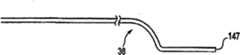
在其它优选实施例中,传递套管36可以包括多个预设曲形部,以允许矫正材料在腔内更好地传递。参照图5A和5B,示出优选的另外传递套管构造。在具有多个预设曲形部的这些构造的每一个中,传递套管可以包括开口端147或封闭端148并且包含一个或多个侧孔149。具有多个预设曲形部的传递套管可以根据这里上述的方向成形并且具有形状记忆特性。In other preferred embodiments, the
无论正确的构造如何,根据本发明原理的组装后的传递套管装置(诸如图4中的传递套管装置26)在进行各种骨稳固手术中作为整个矫正材料传递系统的一部分是非常有用的。在此方面,图6A图示根据本发明一个实施例的用于进行椎体成形术手术的骨内矫正材料传递系统150。该系统150包括外导向管22、传递套管装置26、流体耦合到传递套管装置26的矫正材料源152以及至少耦合到矫正材料源152的控制器154。Regardless of proper configuration, an assembled delivery cannula device according to the principles of the present invention, such as
在一个实施例中,矫正材料源152包括如上所述容纳矫正材料的罐160以及从罐160延伸到传递套管装置26的操作柄组件30的管道164。在此方面,管道164终止于构造成可移除地附装到集线器34的接头配件166。具体而言,接头配件166构造成装配在操作柄40的通道52内并且可移除地耦合到集线器34。在一个实施例中,接头配件166拧到由集线器34所限定的鲁尔螺纹中。在一个实施例中,集线器166包覆成形到传递套管34上。可选地,各种其它附装构造也是可以的。In one embodiment, the source of
控制器154可以呈现本领域中已知的任何形式,并且耦合到矫正材料源152。在一个示例性实施例中,控制器154控制从罐160到传递套管装置26的矫正材料的质流和质流速率(即,流体传递速率)。控制器154可以包括为使用者提供远程控制流入传递套管36的流体的能力的各种致动器(例如,开关、脚踏板等)。可选地,可以使用手动控制,使得可以取消控制器154。The
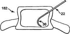
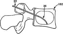
在姑息骨手术过程中,在传递套管36部分缩回在外导向管22内或完全从外导向管22中移除的情况下,外导向管22定位在骨头内的期望传递部位。例如,在椎体成形术手术中,外导向管22引入到脊椎骨180,优选地在蒂182处。在此方面,脊椎骨180包括限定包围体材料(松质骨、血液、骨髓以及其它软组织)188的脊椎壁186的脊椎主体184。蒂182从脊椎主体184延伸并且包围脊椎孔190。具体而言,蒂182在后部附装到脊椎主体184并且它们一起包括椎骨180并形成脊椎孔190的壁。作为参考,骨内系统150适于接近各种骨部位。因此,虽然图示脊椎骨180,但是应当理解,其它骨部位可以被系统150接近(即,股骨、长骨、肋骨、骶骨等)。With the
外导向管22形成到通过蒂182到体材料188中的传递部位192(或形成传递部位192)的接近路径。因此,如图示,外导向管22已经通过经椎弓根接近方法被驱动穿过蒂182。经椎弓根接近方法将外导向管22定位在乳突和蒂182的腰椎副突之间。以此方式,外导向管22在开口远端尖部28处提供到传递部位192的通路。在其它构造的情况下,外导向管22可以类似地进行类穿刺手术,其在骨头内形成扩大开口。在图6A所图示的一个优选实施例中,导向管22的远端尖部28定位成靠近到传递部位192的入口点。如这里更详细解释,远端尖部28进入传递部位192的突出越小,则允许定位在传递部位192内的传递套管36的更大通路,并且允许将矫正材料传递到传递部位192内的期望位置。
一旦形成外导向管22或者其定位在骨头内的期望传递部位192,传递套管36可滑动地插入/远端前进到外导向管22内。如图6A中总体图示,传递套管36的远端部82平衡在外导向管22的远端尖部28处。第一深度记号110a与操作柄30的大致对准在视觉上为使用者提供远端部82相对于外导向管22的远端尖部28定位的确认。在进一步远端运动之前,传递套管36完全在外导向管22内,使得传递套管36的可变形段88(图2A)被强制(即,弯曲)成与外导向管22的形状基本一致的基本直的形状。此关系在图6B中更清楚地示出,由此由于可变形段88在“自然”状态下所限定的曲率半径R(图2A)大于导向管22的内径的原因,通过导向管22将力更有效地施加到可变形段88。这个相互作用基本上“去除”弯曲部90(2A)的预设曲率,强制或造成可变形段88变为基本直的状态(应当理解,因为导向管22的内径大于传递套管36的外径,可变形段88将持续在导向管22内具有稍微弯曲;因此,“基本直的”是指传递套管36为大致但不是完全为直线的)。因此,在与传递部位192(图6A)相互作用之前,传递套管36在外导向管22内弯曲成基本直的、非曲形的取向。Once the
传递套管装置26(具体而言,传递套管36)然后远端前进到导向管22内,如图6C所示。具体而言,传递套管36在远端上被操纵,使得至少一部分可变形段88延伸超过导向管22的开口尖部28并进入传递部位192。现在可变形段88的未受限制部分在离开导向管22的情况下自然侧向变形(从上述的基本直的形状),由于形状记忆特性而恢复到先前描述的弯曲部90的预设曲率。使用者可以通过记号110b或110c(记号110c在图6C中可以看见)相对于操作柄30的纵向定位而在视觉上确认传递导管36从导向管22的远端延伸长度。此外,方向标记114为使用者(在患者外侧的点)指示弯曲部90在传递部位192内相对于操作柄40的空间位置的空间方向。Delivery cannula device 26 (specifically, delivery cannula 36 ) is then advanced distally into
与传递套管36的远端前进相联系,远端部82的钝的尖部100为半球形状(或者为非半球形状或钝的形状)并且由此防止接触组织/骨头的损伤。以此方式,在刺破或穿刺脊椎主体184的很小风险的情况下,钝的尖部100可以接触和/或探测脊椎壁186。因此,钝的尖部100提供优于传统、锋利边缘的骨接合剂传递针的优点,并且,因为使用曲形针的必然性,不需要单独的线来防止穿刺。In connection with distal advancement of the
侧孔84从远端部82偏移,并且因此,可用于将矫正材料传递到传递部位192并从传递部位192移除体材料。具体而言,侧孔84可以容易地从传递套管36注射矫正材料并且从传递套管36抽吸体材料,即使在远端部82压靠在诸如脊椎体184的内壁之类的表面时。
在上述情况下,在一个实施例中,然后(例如,通过控制器154)操作流体源152以将矫正材料(未示出)经由集线器34传递到传递套管36。进入传递套管36的矫正材料被强迫穿过腔86(图2A)朝向侧孔84。如图6D所示,矫正材料然后从传递套管36以从侧孔84的径向方式分配/注射并且以云状图案194进入传递部位192。可选地或除此之外,传递部位192可以通过使用真空源(未示出)代替矫正材料源152(图6A)而被抽吸。With the foregoing in place, in one embodiment,
在另一个实施例中,矫正材料在将传递套管36引入到导向管22中之前被传递到传递套管36。在实践中,操作者可以将矫正材料前进超出传递套管36的侧孔84,以完成填充传递套管36并且然后在插入导向管22之前将侧孔84的多余矫正材料擦除。传递套管36因此在传递套管36与导向管22连接之前预载有矫正材料。一旦传递套管36插入导向管22中,矫正材料立即可以用于传递到植入位置。这个预载步骤有利于减少将矫正材料传递到患者中所需的时间,因为其可以在将导向管22驱动进入传递部位的基本同一时间完成。In another embodiment, the orthotic material is delivered to the
重要的是,通过沿径向从传递套管36的一侧而不是沿轴向从最远端(如使用传统传递针所发生的)注射矫正材料,系统150(图6A)可以避免将矫正材料强迫进入裂缝或其它破损,这接着可能导致矫正材料穿过裂缝的不期望泄漏。作为示例,图6D图示脊椎主体壁186中的裂缝196。椎体成形术是对于这种脊椎裂缝的普通解决方法,使用接受的修复技术使得能够将远端部82定位在裂缝196处或者“面向”裂缝196,以确保矫正材料以非常接近其的方式分配。使用已知的传递针,此优选接近方法导致矫正材料直接朝向裂缝196注射。相反,使用本发明的传递导管36,远端部82也“面向”裂缝196,但是注射的矫正材料云194不是直接强迫朝向裂缝196。作为替代,矫正材料云194以非常小的保持推动力间接到达裂缝196,使得矫正材料云194不可能被迫通过裂缝196而“泄漏”。但是,传递部位192作为整体仍填充有矫正材料云194,以实现期望的修复。Importantly, by injecting the orthotic material radially from one side of the
如图6D所示,全部传递部位192可以被传递套管36所接近。在此方面,虽然导向管22已经通过正确的后部侧向接近方法插入,系统150可以通过左侧后部侧向接近方法或者如图6E中所示的右侧或左侧后部侧向接近方法实现椎体成形术手术。As shown in FIG. 6D , all
在一个实施例中,返回图6C,期望数量的矫正材料完全通过传递套管36传递。在根据本发明原理的其它实施例中,在将第一数量的矫正材料通过传递套管36注射后,传递套管36与矫正材料源152分离并且从导向管22移除。矫正材料源152然后与导向管22流体连接(例如,接头配件166与设置有操作柄30的对应流体端口/集线器流体连接)并且然后操作以将第二数量的矫正材料通过导向管22注射到传递部位192。In one embodiment, returning to FIG. 6C , the desired amount of orthotic material is delivered entirely through
在另一个优选实施例中,供应矫正材料的管道164旋转耦合到传递套管装置26。进一步参照图6C,在一个实施例中,可选的旋转连接器29定位在传递套管26和矫正材料源152之间,以允许传递套管26和矫正材料源152彼此相对旋转。适于矫正材料传递装置的旋转连接器在美国专利申请No.11/526,164中描述,通过参考该专利申请关于旋转连接器的公开而将其结合于此。在此实施例中,旋转连接器29允许医师旋转传递套管26,并且由此在不需要将矫正材料源与传递套管26分离或者相对于传递套管旋转的情况下旋转植入部位内的传递套管26的曲形端。在优选实施例中,旋转连接器29可操作以旋转传递套管26,优选约90度,更优选为约360度。In another preferred embodiment, a
更总体而言,在姑息骨手术过程中,操作骨内系统150的临床医师将预设弯曲部90的一部分延伸进入骨头内所限定的传递部位192。在一个实施例中,传递套管36的后续旋转相对于传递部位192旋转侧孔84的空间位置,由此仅使用外导向管22的一次“刺入”而接近传递部位192的多个平面。因此,通过结合将传递套管36缩进外导向管22内、相对于外导向管22远端前进传递套管36以及通过旋转传递套管36,通过传递套管36使用外导向管22的单次接近方法可以接近感兴趣的骨部位的多个平面和多个区域。因此,例如,经单侧椎体成形术可以使用系统150完成。图7A-8B总体图示(图7A和7B从内部角度;图8A和8B从左侧角度)在传递套管36相对于导向管22的旋转和/或前进(在导向管22保持静止的情况下)可以接近的脊椎主体182的各个平面/区域。注意,在图7A-8B中,传递套管36所限定的弯曲的方向不一定垂直于页面,由此弯曲在每个视图中可能不是非常明显的。More generally, during palliative bone surgery, a clinician operating the
参照图9-10,描述用于传递矫正材料的另一个优选方法。在此优选实施例中,临床医师通过操作传递套管36的弯曲部90而在骨传递部位内的软体组织材料200(例如,松质骨、血液、骨髓和其它软组织)中产生空洞210。空洞210然后用矫正材料填充。已经发现,当产生空洞时,传递到传递部位的矫正材料一般流入空洞210而不是软体材料200中。结果,临床医师可以在相对小的期望区域产生空洞210,并且使用矫正材料而主要填充此区域。Another preferred method for delivering orthotic material is described with reference to Figures 9-10. In this preferred embodiment, the clinician creates a
根据一个优选实施例,可以通过下面方式产生空洞:组合将传递套管36缩进外导向管22以及相对于外导向管22而远端前进传递导管36,由此以往复形式移动弯曲部90。往复动作使得弯曲部90压碎软体组织并在软体组织内产生通道212。另外,通过将传递套管36缩进外导向管22内并且旋转传递套管36使得弯曲部90以不同取向远端前进到传递部位内,弯曲部90可以在软体组织200内产生多个通道212。此外,传递套管36的弯曲部90可以仅部分前进到传递部位并且然后被移除以在期望植入的植入部位内产生较短通道212。According to a preferred embodiment, the cavity may be created by a combination of retracting
根据图10所示的另一个优选实施例,在弯曲部90已经引入植入部位后,传递套管36可以旋转或转动。传递套管36的旋转或转动使得弯曲部90在传递部位内旋转或转动并且迅速移动穿过软体组织200,以在传递部位内在软体组织200中产生锥形空洞214。通过将弯曲部90仅部分插入植入部位并旋转传递套管36,可以产生各种尺寸的锥形空洞214。According to another preferred embodiment shown in Fig. 10, the
软体组织内的各种尺寸和形状的空洞210可以通过组合上述方法来产生。根据一个优选实施例,医师可以在其在植入部位内产生空洞时将矫正材料引入到植入部位内。因此,可以同时产生和填充空洞。
本领域的一般技术人员可以理解,无论首先产生并然后填充空洞还是在不首先产生空洞的情况下以云状图案传递矫正材料,可以操作本发明的传递套管,以将较小沉积的矫正材料传递到腔内的具体期望区域。Those of ordinary skill in the art will appreciate that the delivery sleeve of the present invention can be operated to transfer smaller deposits of remedial material, whether the voids are first created and then filled, or the remedial material is delivered in a cloud-like pattern without first creating the voids. Delivery to specific desired areas within the lumen.
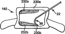
在一个实施例中,矫正材料可以在不同平面中传递,以在腔内形成矫正材料结构,以稳固脊椎主体的终板,如图1A和1B所示。在一个优选实施例中,矫正材料232a和232b接近脊椎主体的终板230a和230b沉积,使得矫正材料与终板230a和230b基本干涉,并且提供结构支撑。根据一个优选实施例,手术在矫正材料沉积232a和232b之间留下基本不包含矫正材料的区域。矫正材料因此可以仅沉积在腔的特定区域中。In one embodiment, the orthotic material may be delivered in different planes to form an orthotic structure within the lumen to stabilize the endplates of the vertebral body, as shown in FIGS. 1A and 1B . In a preferred embodiment, the
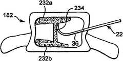
参照图11C,在另一个优选实施例中,矫正材料沉积232a和232b可以通过在矫正材料沉积232a和232b之间放置矫正材料以形成矫正材料稳固柱234而连接。在此实施例中,首先产生矫正材料沉积232a和232b,以稳固脊椎主体的终板。然后在矫正材料沉积232a和232b之间产生稳固矫正材料234,以连接矫正材料沉积并在脊椎主体内形成矫正材料结构。通过首先稳固终板,可以稳固由于压缩裂缝引起的畸形。通过稳固两个终板并然后在终板之间产生柱型结构,脊椎主体硬度可以显著提高,由此最小化脊椎主体的整体强度的问题。已经发现,以将材料沉积在脊椎主体中心的已知方法沉积矫正材料(通常称为椎体后凸成形术手术)或者将材料分散在整个脊椎主体中(通常称为椎体成形术手术)都不能够均质地加固脊椎主体。因为接合剂集中在部位区域,所以终板存在仅最小化的稳固。通过稳固两个终板并然后提供将其固定在一个的结构,当与已知的椎体成形术或椎体后凸成形术手术相比时,修复的脊椎主体硬度更接近非骨折脊椎主体的正常硬度。在另一个实施例中,如果诊断压缩裂缝更可能发生在终板上,则可仅需要稳固一个终板并且接近脊椎终板仅产生一个矫正材料沉积。在此实施例中,可以产生支撑结构,以连接矫正材料和与修复的脊椎终板相对的脊椎终板。Referring to FIG. 11C , in another preferred embodiment,
参照图12,描述用于传递矫正材料的另一个优选方法。在此优选实施例中,传递部位是骶骨220。在此实施例中,矫正材料传递到骶骨220,以修复骶骨中的骨折片或裂缝。根据本发明的一个优选方法,矫正材料通过单一通路点而传递到骶骨内的多个区域。优选地,导向管22大体上插入在骶骨的中间部分。如上所述,曲形针插入导向管22并相对于导向管22前进。传递套管36优选地取向,使得弯曲部90进入接近骶骨220的第一区域221。矫正材料然后传递到骶骨220的第一区域221。在矫正材料传递到第一区域221后,医师然后可以将弯曲部90部分或全部缩回导向管内并且然后重新为传递套管36和弯曲部90取向。因为传递套管36再次相对于导向管22前进,所以弯曲部90进入接近骶骨220的第二区域222。矫正材料然后传递到骶骨220的第二区域222。对于其它区域,可以重复此处理。虽然上述的植入部位是骶骨,通过使用上述方法通过相同通路点将矫正材料传递到多个区域,可以修复其它骨头中的裂缝。Referring to Figure 12, another preferred method for delivering orthotic material is described. In this preferred embodiment, the delivery site is the
虽然这里已经图示和描述了具体实施例,但是本领域的一般技术人员应当理解,在不偏离本发明的范围内,多种可选和/或等同实现方法可以取代示出的和描述的具体实施例。本发明意欲覆盖这里讨论的具体实施例的任何适应性修改或变化。因此,本发明不仅局限于权利要求及其等同方案。例如,虽然具体针对椎体成形术手术,但是根据本发明原理的装置、系统和方法同样可以应用到将矫正材料传递到患者的多个其它骨头内。Although specific embodiments have been illustrated and described herein, those skilled in the art should understand that various alternative and/or equivalent implementation methods may replace the specific embodiments shown and described without departing from the scope of the present invention. Example. This invention is intended to cover any adaptations or variations of the specific embodiments discussed herein. Accordingly, the invention is not to be limited only by the claims and their equivalents. For example, while directed specifically to vertebroplasty procedures, devices, systems and methods in accordance with the principles of the present invention are equally applicable to delivering corrective material into a variety of other bones of a patient.
Claims (8)
Translated fromChineseApplications Claiming Priority (3)
| Application Number | Priority Date | Filing Date | Title |
|---|---|---|---|
| US11/704,139 | 2007-02-08 | ||
| US11/704,139US7799035B2 (en) | 2005-11-18 | 2007-02-08 | Device, system and method for delivering a curable material into bone |
| PCT/US2008/001747WO2008097659A2 (en) | 2007-02-08 | 2008-02-08 | Device, system and method for delivering a curable material into bone |
Related Child Applications (1)
| Application Number | Title | Priority Date | Filing Date |
|---|---|---|---|
| CN2011100495937ADivisionCN102166131A (en) | 2007-02-08 | 2008-02-08 | Devices, systems and methods for delivering orthotic material into bone |
Publications (2)
| Publication Number | Publication Date |
|---|---|
| CN101720207A CN101720207A (en) | 2010-06-02 |
| CN101720207Btrue CN101720207B (en) | 2011-10-05 |
Family
ID=39386129
Family Applications (2)
| Application Number | Title | Priority Date | Filing Date |
|---|---|---|---|
| CN2011100495937APendingCN102166131A (en) | 2007-02-08 | 2008-02-08 | Devices, systems and methods for delivering orthotic material into bone |
| CN2008800114166AExpired - Fee RelatedCN101720207B (en) | 2007-02-08 | 2008-02-08 | Devices, systems and methods for delivering orthotic material into bone |
Family Applications Before (1)
| Application Number | Title | Priority Date | Filing Date |
|---|---|---|---|
| CN2011100495937APendingCN102166131A (en) | 2007-02-08 | 2008-02-08 | Devices, systems and methods for delivering orthotic material into bone |
Country Status (11)
| Country | Link |
|---|---|
| US (3) | US7799035B2 (en) |
| EP (1) | EP2117455A2 (en) |
| JP (1) | JP2010517683A (en) |
| CN (2) | CN102166131A (en) |
| AU (1) | AU2008214200B2 (en) |
| BR (1) | BRPI0807229A2 (en) |
| CA (1) | CA2677644C (en) |
| NZ (1) | NZ579020A (en) |
| RU (1) | RU2009130398A (en) |
| WO (1) | WO2008097659A2 (en) |
| ZA (1) | ZA200905547B (en) |
Families Citing this family (147)
| Publication number | Priority date | Publication date | Assignee | Title |
|---|---|---|---|---|
| US8361067B2 (en) | 2002-09-30 | 2013-01-29 | Relievant Medsystems, Inc. | Methods of therapeutically heating a vertebral body to treat back pain |
| US6907884B2 (en) | 2002-09-30 | 2005-06-21 | Depay Acromed, Inc. | Method of straddling an intraosseous nerve |
| US7258690B2 (en) | 2003-03-28 | 2007-08-21 | Relievant Medsystems, Inc. | Windowed thermal ablation probe |
| ES2545328T3 (en) | 2003-03-14 | 2015-09-10 | Depuy Spine, Inc. | Bone cement hydraulic injection device in percutaneous vertebroplasty |
| US8066713B2 (en) | 2003-03-31 | 2011-11-29 | Depuy Spine, Inc. | Remotely-activated vertebroplasty injection device |
| US8415407B2 (en) | 2004-03-21 | 2013-04-09 | Depuy Spine, Inc. | Methods, materials, and apparatus for treating bone and other tissue |
| US8579908B2 (en) | 2003-09-26 | 2013-11-12 | DePuy Synthes Products, LLC. | Device for delivering viscous material |
| CN101065080B (en) | 2004-07-30 | 2021-10-29 | 德普伊新特斯产品有限责任公司 | Materials and Instruments for Manipulating Bone and Other Tissues |
| US8092464B2 (en)* | 2005-04-30 | 2012-01-10 | Warsaw Orthopedic, Inc. | Syringe devices and methods useful for delivering osteogenic material |
| US9381024B2 (en) | 2005-07-31 | 2016-07-05 | DePuy Synthes Products, Inc. | Marked tools |
| US9918767B2 (en) | 2005-08-01 | 2018-03-20 | DePuy Synthes Products, Inc. | Temperature control system |
| US8366773B2 (en) | 2005-08-16 | 2013-02-05 | Benvenue Medical, Inc. | Apparatus and method for treating bone |
| ES2531134T3 (en)* | 2005-09-07 | 2015-03-11 | Thomas Steffen | Device for injection of high viscosity material |
| DE102005053819A1 (en)* | 2005-11-11 | 2007-05-16 | Khd Humboldt Wedag Gmbh | Rotary kiln burner |
| US7799035B2 (en)* | 2005-11-18 | 2010-09-21 | Carefusion 2200, Inc. | Device, system and method for delivering a curable material into bone |
| US8690884B2 (en) | 2005-11-18 | 2014-04-08 | Carefusion 2200, Inc. | Multistate-curvature device and method for delivering a curable material into bone |
| US8360629B2 (en) | 2005-11-22 | 2013-01-29 | Depuy Spine, Inc. | Mixing apparatus having central and planetary mixing elements |
| US7922690B2 (en)* | 2006-02-22 | 2011-04-12 | Michael Plishka | Curable material delivery device |
| US8361032B2 (en)* | 2006-02-22 | 2013-01-29 | Carefusion 2200 Inc. | Curable material delivery device with a rotatable supply section |
| WO2007122608A2 (en)* | 2006-04-20 | 2007-11-01 | Depuy Spine, Inc. | Instrumentation kit for delivering viscous bone filler material |
| US20070260258A1 (en)* | 2006-05-05 | 2007-11-08 | Robert Sommerich | Access and delivery needle for percutaneous vertebroplasty |
| AU2007297097A1 (en) | 2006-09-14 | 2008-03-20 | Depuy Spine, Inc. | Bone cement and methods of use thereof |
| US8950929B2 (en) | 2006-10-19 | 2015-02-10 | DePuy Synthes Products, LLC | Fluid delivery system |
| US8414587B2 (en)* | 2007-01-26 | 2013-04-09 | Laurimed, Llc | Styli used to position device for carrying out selective discetomy |
| WO2008140519A1 (en)* | 2007-05-10 | 2008-11-20 | Depuy Spine, Inc. | Improved access delivery needle for percutaneous vertebroplasty |
| CN101801445B (en) | 2007-08-14 | 2013-04-17 | 弗雷德哈钦森癌症研究中心 | Needle Array Assembly for Delivery of Therapeutic Drugs |
| US20090088789A1 (en)* | 2007-09-28 | 2009-04-02 | O'neil Michael J | Balloon With Shape Control For Spinal Procedures |
| US9510885B2 (en) | 2007-11-16 | 2016-12-06 | Osseon Llc | Steerable and curvable cavity creation system |
| US20090131867A1 (en) | 2007-11-16 | 2009-05-21 | Liu Y King | Steerable vertebroplasty system with cavity creation element |
| WO2011066465A1 (en)* | 2009-11-25 | 2011-06-03 | Osseon Therapeutics, Inc. | Steerable and curvable vertebroplasty system with clog-resistant exit ports |
| US8540720B2 (en) | 2007-12-06 | 2013-09-24 | Javier Garcia-Bengochea | System, instrumentation and method for spinal fixation using minimally invasive surgical techniques |
| US8282648B2 (en) | 2007-12-19 | 2012-10-09 | Cook Medical Technologies Llc | Bone cement needle |
| US8088163B1 (en) | 2008-02-06 | 2012-01-03 | Kleiner Jeffrey B | Tools and methods for spinal fusion |
| US20090209853A1 (en)* | 2008-02-19 | 2009-08-20 | Parihar Shailendra K | Biopsy site marker applier |
| FR2929099B1 (en)* | 2008-03-28 | 2011-05-06 | Jean Charles Persat | DEVICE FOR THE INJECTION IN THE ORGANISM OF A VISCOUS FLUID |
| WO2009124192A1 (en)* | 2008-04-02 | 2009-10-08 | Laurimed, Llc | Methods and devices for delivering injections |
| US20210378834A1 (en) | 2008-05-22 | 2021-12-09 | Spinal Surgical Strategies, Inc., A Nevada Corporation D/B/A Kleiner Device Labs | Spinal fusion cage system with inserter |
| US8100859B2 (en)* | 2008-06-24 | 2012-01-24 | Cook Medical Technologies Llc | Bent obturator |
| US8277506B2 (en)* | 2008-06-24 | 2012-10-02 | Carefusion 2200, Inc. | Method and structure for stabilizing a vertebral body |
| EP2307075B1 (en)* | 2008-07-15 | 2015-11-11 | Thomas Steffen | Bone cement injection device |
| CA2737374C (en) | 2008-09-26 | 2017-03-28 | Relievant Medsystems, Inc. | Systems and methods for navigating an instrument through bone |
| US10028753B2 (en) | 2008-09-26 | 2018-07-24 | Relievant Medsystems, Inc. | Spine treatment kits |
| USD853560S1 (en) | 2008-10-09 | 2019-07-09 | Nuvasive, Inc. | Spinal implant insertion device |
| US8366748B2 (en) | 2008-12-05 | 2013-02-05 | Kleiner Jeffrey | Apparatus and method of spinal implant and fusion |
| USD656610S1 (en) | 2009-02-06 | 2012-03-27 | Kleiner Jeffrey B | Spinal distraction instrument |
| US9247943B1 (en) | 2009-02-06 | 2016-02-02 | Kleiner Intellectual Property, Llc | Devices and methods for preparing an intervertebral workspace |
| EP2416721B1 (en)* | 2009-04-09 | 2013-07-10 | Synthes GmbH | Minimally invasive spine augmentation and stabilization system |
| US20100298832A1 (en) | 2009-05-20 | 2010-11-25 | Osseon Therapeutics, Inc. | Steerable curvable vertebroplasty drill |
| US9241720B2 (en)* | 2009-07-10 | 2016-01-26 | Peter Forsell | Hip joint instrument and method |
| US9060877B2 (en) | 2009-09-18 | 2015-06-23 | Spinal Surgical Strategies, Llc | Fusion cage with combined biological delivery system |
| US8685031B2 (en) | 2009-09-18 | 2014-04-01 | Spinal Surgical Strategies, Llc | Bone graft delivery system |
| US10245159B1 (en) | 2009-09-18 | 2019-04-02 | Spinal Surgical Strategies, Llc | Bone graft delivery system and method for using same |
| US20170238984A1 (en) | 2009-09-18 | 2017-08-24 | Spinal Surgical Strategies, Llc | Bone graft delivery device with positioning handle |
| USD750249S1 (en) | 2014-10-20 | 2016-02-23 | Spinal Surgical Strategies, Llc | Expandable fusion cage |
| US8906028B2 (en) | 2009-09-18 | 2014-12-09 | Spinal Surgical Strategies, Llc | Bone graft delivery device and method of using the same |
| US10973656B2 (en) | 2009-09-18 | 2021-04-13 | Spinal Surgical Strategies, Inc. | Bone graft delivery system and method for using same |
| US9629729B2 (en) | 2009-09-18 | 2017-04-25 | Spinal Surgical Strategies, Llc | Biological delivery system with adaptable fusion cage interface |
| US9186193B2 (en) | 2009-09-18 | 2015-11-17 | Spinal Surgical Strategies, Llc | Fusion cage with combined biological delivery system |
| US9173694B2 (en) | 2009-09-18 | 2015-11-03 | Spinal Surgical Strategies, Llc | Fusion cage with combined biological delivery system |
| USD723682S1 (en) | 2013-05-03 | 2015-03-03 | Spinal Surgical Strategies, Llc | Bone graft delivery tool |
| US20110071391A1 (en)* | 2009-09-24 | 2011-03-24 | Speeg Trevor W V | Biopsy marker delivery device with positioning component |
| US8529465B2 (en)* | 2009-09-24 | 2013-09-10 | Devicor Medical Products, Inc. | Biopsy marker delivery devices and methods |
| JP5538795B2 (en)* | 2009-09-28 | 2014-07-02 | Ntn株式会社 | Remote control type actuator |
| US20110112507A1 (en)* | 2009-11-10 | 2011-05-12 | Carefusion 207, Inc. | Curable material delivery systems and methods |
| US9095393B2 (en) | 2012-05-30 | 2015-08-04 | Carefusion 2200, Inc. | Method for balloon-aided vertebral augmentation |
| US8226657B2 (en) | 2009-11-10 | 2012-07-24 | Carefusion 207, Inc. | Systems and methods for vertebral or other bone structure height restoration and stabilization |
| US8894658B2 (en)* | 2009-11-10 | 2014-11-25 | Carefusion 2200, Inc. | Apparatus and method for stylet-guided vertebral augmentation |
| WO2011082499A1 (en)* | 2010-01-11 | 2011-07-14 | Ao Technology Ag | Cannula and kit for injection of bone cement |
| US20110184518A1 (en)* | 2010-01-22 | 2011-07-28 | Warsaw Orthopedic, Inc. | Sacro-iliac joint implant |
| US8221428B2 (en)* | 2010-01-26 | 2012-07-17 | Warsaw Orthopedic, Inc. | Sacro-iliac joint implant system, method and instrument |
| US20110184520A1 (en)* | 2010-01-27 | 2011-07-28 | Warsaw Orthopedic, Inc. | Sacro-iliac joint implant, method and apparatus |
| US8945224B2 (en)* | 2010-03-18 | 2015-02-03 | Warsaw, Orthopedic, Inc. | Sacro-iliac implant system, method and apparatus |
| US20110238181A1 (en)* | 2010-03-29 | 2011-09-29 | Warsaw Orthopedic, Inc., A Indiana Corporation | Sacro-iliac joint implant system and method |
| US9125671B2 (en) | 2010-04-29 | 2015-09-08 | Dfine, Inc. | System for use in treatment of vertebral fractures |
| AU2014215982B2 (en)* | 2010-06-30 | 2016-10-20 | Myromed, Llc | Devices and methods for cutting and evacuating tissue |
| US8685052B2 (en) | 2010-06-30 | 2014-04-01 | Laurimed, Llc | Devices and methods for cutting tissue |
| CN103068327B (en) | 2010-06-30 | 2015-08-05 | 劳瑞弥徳有限责任公司 | For excising and withdraw from the apparatus and method of tissue |
| US9144501B1 (en) | 2010-07-16 | 2015-09-29 | Nuvasive, Inc. | Fracture reduction device and methods |
| AU2011305680B2 (en) | 2010-09-20 | 2014-09-11 | Jeffrey Kleiner | Fusion cage with combined biological delivery system |
| US8771276B2 (en) | 2010-12-01 | 2014-07-08 | Carefusion 2200, Inc. | Systems and methods for forming a cavity in, and delivering curable material into, bone |
| US9039765B2 (en) | 2011-01-21 | 2015-05-26 | Warsaw Orhtopedic, Inc. | Implant system and method for stabilization of a sacro-iliac joint |
| US9060878B2 (en) | 2011-03-28 | 2015-06-23 | Ray G. Oktavec | Percutaneous biologic delivery system |
| CA2831057C (en) | 2011-04-19 | 2017-08-15 | Ao Technology Ag | Cannula and kit for evaluation and preparation of bone tissue |
| EP2717808A2 (en)* | 2011-06-09 | 2014-04-16 | Zimmer GmbH | Instruments and devices for subchondral joint repair |
| US8814873B2 (en) | 2011-06-24 | 2014-08-26 | Benvenue Medical, Inc. | Devices and methods for treating bone tissue |
| US20130012951A1 (en)* | 2011-07-08 | 2013-01-10 | Carefusion 207, Inc. | Systems and methods for treating a spine through a single vertebral body insertion point |
| US9119639B2 (en) | 2011-08-09 | 2015-09-01 | DePuy Synthes Products, Inc. | Articulated cavity creator |
| US20130072941A1 (en)* | 2011-09-16 | 2013-03-21 | Francisca Tan-Malecki | Cement Injector and Cement Injector Connectors, and Bone Cement Injector Assembly |
| SG10201508662SA (en) | 2011-10-28 | 2015-11-27 | Presage Biosciences Inc | Methods for drug delivery |
| AU2012362524B2 (en) | 2011-12-30 | 2018-12-13 | Relievant Medsystems, Inc. | Systems and methods for treating back pain |
| CN104168846B (en)* | 2012-02-10 | 2017-11-14 | Dolor科技有限公司 | Beneficial to the system and apparatus of patient's intranasal treatment |
| WO2013119336A1 (en) | 2012-02-10 | 2013-08-15 | Laurimed, Llc | Vacuum powered rotary devices and methods |
| CN102670288B (en)* | 2012-06-05 | 2013-11-27 | 南安新领医疗技术开发有限公司 | Full vertebral body multiple-point bone cement injection needle |
| CN102784434B (en)* | 2012-08-31 | 2013-12-04 | 宁波华科润生物科技有限公司 | Bone filler conveying sleeve |
| WO2014045124A2 (en)* | 2012-09-07 | 2014-03-27 | Zimmer Knee Creations, Inc. | Instruments for controlled delivery of injectable materials into bone |
| US10588691B2 (en) | 2012-09-12 | 2020-03-17 | Relievant Medsystems, Inc. | Radiofrequency ablation of tissue within a vertebral body |
| WO2014071161A1 (en) | 2012-11-05 | 2014-05-08 | Relievant Medsystems, Inc. | System and methods for creating curved paths through bone and modulating nerves within the bone |
| US9439693B2 (en) | 2013-02-01 | 2016-09-13 | DePuy Synthes Products, Inc. | Steerable needle assembly for use in vertebral body augmentation |
| US9717551B2 (en) | 2013-02-21 | 2017-08-01 | Carefusion 2200, Inc. | Intravertebral tissue ablation device and method |
| WO2014134624A1 (en)* | 2013-03-01 | 2014-09-04 | The Arizona Board Of Regents On Behalf Of The University Of Arizona | Modified veress needle for tension pneumothorax decompression |
| US20140276591A1 (en)* | 2013-03-14 | 2014-09-18 | Mi4Spine, Llc | Percutaneous intervertebral annular regeneration |
| US10085783B2 (en) | 2013-03-14 | 2018-10-02 | Izi Medical Products, Llc | Devices and methods for treating bone tissue |
| CN103251445B (en)* | 2013-04-19 | 2015-04-22 | 南京医科大学第一附属医院 | Device for operating vertebroplasty through unilateral vertebral pedicle |
| US9724151B2 (en) | 2013-08-08 | 2017-08-08 | Relievant Medsystems, Inc. | Modulating nerves within bone using bone fasteners |
| US9808237B2 (en)* | 2013-09-26 | 2017-11-07 | Depuy Mitek, Llc | Methods and devices for passing sutures around anatomical structures |
| EP3054879A1 (en) | 2013-10-09 | 2016-08-17 | CareFusion 2200 Inc. | Systems for balloon-aided vertebral augmentation |
| EP3057517B1 (en) | 2013-10-15 | 2020-04-08 | Stryker Corporation | Device for creating a void space in a living tissue, the device including a handle with a control knob that can be set regardless of the orientation of the handle |
| US9351739B2 (en) | 2013-12-31 | 2016-05-31 | Amendia, Inc. | Tunneling device |
| US8815099B1 (en) | 2014-01-21 | 2014-08-26 | Laurimed, Llc | Devices and methods for filtering and/or collecting tissue |
| US9968373B1 (en)* | 2014-02-21 | 2018-05-15 | Surgentec, Llc | Handles for needle assemblies |
| US9393061B2 (en) | 2014-03-17 | 2016-07-19 | Stryker Corporation | Method for balloon-assisted augmentation and fusion of adjacent vertebral bodies |
| EP3142541A4 (en) | 2014-05-13 | 2017-04-26 | Vycor Medical, Inc. | Guidance system mounts for surgical introducers |
| US10350387B2 (en)* | 2014-06-02 | 2019-07-16 | Medtronic, Inc. | Implant tool for substernal or pericardial access |
| US9730707B2 (en) | 2014-08-20 | 2017-08-15 | Kyphon SÀRL | Surgical instrument with graduated markings correlating to angulation |
| US20160310194A1 (en)* | 2015-04-21 | 2016-10-27 | Arthrex, Inc. | Surgical assembly and method for repairing depression fractures |
| USD797290S1 (en) | 2015-10-19 | 2017-09-12 | Spinal Surgical Strategies, Llc | Bone graft delivery tool |
| AU2016388454A1 (en)* | 2016-01-18 | 2018-07-19 | Covidien Lp | Endoscopic surgical clip applier |
| US11364062B2 (en) | 2016-08-18 | 2022-06-21 | Spinal Elements, Inc. | Material delivery surgical device |
| CN106691571A (en)* | 2016-08-29 | 2017-05-24 | 宁波华科润生物科技有限公司 | Transport cannula for skeleton filler |
| EP3528723B1 (en) | 2016-10-27 | 2023-08-16 | C. R. Bard, Inc. | Intraosseous access device |
| JP2019534130A (en) | 2016-10-27 | 2019-11-28 | ディーファイン,インコーポレイティド | Articulated osteotome with cement delivery channel |
| US10080671B2 (en)* | 2016-11-01 | 2018-09-25 | Warsaw Orhtopedic, Inc. | Trial and method for use thereof |
| US11033665B2 (en) | 2016-11-04 | 2021-06-15 | The Arizona Board Of Regents On Behalf Of The University Of Arizona | Modified veress needle assembly for tension pneumothorax decompression |
| US10376258B2 (en)* | 2016-11-07 | 2019-08-13 | Vycor Medical, Inc. | Surgical introducer with guidance system receptacle |
| US10543016B2 (en) | 2016-11-07 | 2020-01-28 | Vycor Medical, Inc. | Surgical introducer with guidance system receptacle |
| US12178469B2 (en) | 2016-11-07 | 2024-12-31 | Vycor Medical Inc. | Surgical introducer with guidance system receptacle |
| CA3041114A1 (en) | 2016-11-28 | 2018-05-31 | Dfine, Inc. | Tumor ablation devices and related methods |
| US10470781B2 (en) | 2016-12-09 | 2019-11-12 | Dfine, Inc. | Medical devices for treating hard tissues and related methods |
| US10660656B2 (en) | 2017-01-06 | 2020-05-26 | Dfine, Inc. | Osteotome with a distal portion for simultaneous advancement and articulation |
| EP3357459A1 (en) | 2017-02-03 | 2018-08-08 | Spinal Surgical Strategies, LLC | Bone graft delivery device with positioning handle |
| US12296133B2 (en)* | 2017-03-14 | 2025-05-13 | Spinal Generations, Llc | Fluid delivery device and bone screw |
| KR102061031B1 (en)* | 2017-11-14 | 2019-12-31 | 주식회사 엔도비전 | Injection device of Bone Wax in body using for Hemostasis |
| US20210212728A1 (en)* | 2018-05-29 | 2021-07-15 | Greening Investments Pty Ltd | Needle for harvesting human eggs |
| US11937864B2 (en) | 2018-11-08 | 2024-03-26 | Dfine, Inc. | Ablation systems with parameter-based modulation and related devices and methods |
| US11849986B2 (en) | 2019-04-24 | 2023-12-26 | Stryker Corporation | Systems and methods for off-axis augmentation of a vertebral body |
| AU2020346827A1 (en) | 2019-09-12 | 2022-03-31 | Relievant Medsystems, Inc. | Systems and methods for tissue modulation |
| US11986229B2 (en) | 2019-09-18 | 2024-05-21 | Merit Medical Systems, Inc. | Osteotome with inflatable portion and multiwire articulation |
| WO2021062215A1 (en)* | 2019-09-27 | 2021-04-01 | Bard Access Systems, Inc. | Step needle for intraosseous access device |
| CN111053606B (en)* | 2019-12-18 | 2025-06-24 | 山东明德生物医学工程有限公司 | Integrated injection method and device for injectable bone substitute in vertebral body shaping |
| CN113317840A (en) | 2020-02-28 | 2021-08-31 | 巴德阿克塞斯系统股份有限公司 | Flexible intra-osseous obturator |
| JP7586520B2 (en) | 2020-06-09 | 2024-11-19 | メディケアテック カンパニー リミテッド | Tube member having locally excellent foldability and manufacturing method thereof |
| CN216167681U (en) | 2020-07-17 | 2022-04-05 | 巴德阿克塞斯系统股份有限公司 | Safety mechanism |
| US12082876B1 (en) | 2020-09-28 | 2024-09-10 | Relievant Medsystems, Inc. | Introducer drill |
| EP4268150A4 (en) | 2020-12-22 | 2024-12-18 | Relievant Medsystems, Inc. | PREDICTION OF CANDIDATES FOR SPINAL NEUROMODULATION |
| US12239492B2 (en) | 2021-01-14 | 2025-03-04 | Medtronic Holding Company Sárl | Devices, systems, and methods facilitating access to and mapping of target tissue |
| US12329430B2 (en)* | 2021-07-19 | 2025-06-17 | Warsaw Orthopedic, Inc. | Bone material dispensing system and methods of use |
| US12433668B1 (en) | 2021-11-08 | 2025-10-07 | Relievant Medsystems, Inc. | Impedance stoppage mitigation during radiofrequency tissue ablation procedures |
Citations (1)
| Publication number | Priority date | Publication date | Assignee | Title |
|---|---|---|---|---|
| EP1059067A1 (en)* | 1999-06-11 | 2000-12-13 | Sherwood Services AG | Ablation treatment of bone metastases |
Family Cites Families (67)
| Publication number | Priority date | Publication date | Assignee | Title |
|---|---|---|---|---|
| US4265231A (en)* | 1979-04-30 | 1981-05-05 | Scheller Jr Arnold D | Curved drill attachment for bone drilling uses |
| DE3327585A1 (en)* | 1982-08-06 | 1984-02-09 | John Martin Oxford Evans | SURGICAL INSTRUMENT FOR EPIDURAL AND SPINAL ANESTHESIA |
| AU1186388A (en)* | 1987-11-16 | 1989-06-14 | Universitet Druzhby Narodov Imeni Patrisa Lumumby | Trocar |
| US5295980A (en)* | 1989-10-30 | 1994-03-22 | Ersek Robert A | Multi-use cannula system |
| ATE361028T1 (en)* | 1994-01-26 | 2007-05-15 | Kyphon Inc | IMPROVED INFLATABLE DEVICE FOR USE IN SURGICAL METHODS OF FIXATION OF BONE |
| US6241734B1 (en)* | 1998-08-14 | 2001-06-05 | Kyphon, Inc. | Systems and methods for placing materials into bone |
| US6248110B1 (en)* | 1994-01-26 | 2001-06-19 | Kyphon, Inc. | Systems and methods for treating fractured or diseased bone using expandable bodies |
| WO1995020345A1 (en)* | 1994-01-28 | 1995-08-03 | Ep Technologies, Inc. | Minimizing blood contact in cardiac tissue measurements |
| US5601561A (en)* | 1995-01-17 | 1997-02-11 | W. L. Gore & Associates, Inc. | Guided bone rasp |
| US5609629A (en)* | 1995-06-07 | 1997-03-11 | Med Institute, Inc. | Coated implantable medical device |
| US5851209A (en)* | 1996-01-16 | 1998-12-22 | Hospital For Joint Diseases | Bone cerclage tool |
| US5741261A (en)* | 1996-06-25 | 1998-04-21 | Sdgi Holdings, Inc. | Minimally invasive spinal surgical methods and instruments |
| DE19637025A1 (en) | 1996-09-12 | 1998-03-19 | Stephan Herrmann | Pre-evaporating and premixing burner for liquid fuels |
| EP1459691A1 (en) | 1996-10-23 | 2004-09-22 | Oratec Interventions, Inc. | Method and apparatus for treating intervertebral discs |
| US5843103A (en)* | 1997-03-06 | 1998-12-01 | Scimed Life Systems, Inc. | Shaped wire rotational atherectomy device |
| NZ513472A (en)* | 1997-06-09 | 2002-12-20 | Kyphon Inc | Apparatus for treating fractured or diseased bone using plastically expandable bodies |
| US5972015A (en)* | 1997-08-15 | 1999-10-26 | Kyphon Inc. | Expandable, asymetric structures for deployment in interior body regions |
| US6048346A (en)* | 1997-08-13 | 2000-04-11 | Kyphon Inc. | Systems and methods for injecting flowable materials into bones |
| US5928239A (en)* | 1998-03-16 | 1999-07-27 | University Of Washington | Percutaneous surgical cavitation device and method |
| US7572263B2 (en)* | 1998-04-01 | 2009-08-11 | Arthrocare Corporation | High pressure applicator |
| WO1999049819A1 (en)* | 1998-04-01 | 1999-10-07 | Parallax Medical, Inc. | Pressure applicator for hard tissue implant placement |
| US6440138B1 (en)* | 1998-04-06 | 2002-08-27 | Kyphon Inc. | Structures and methods for creating cavities in interior body regions |
| US6296639B1 (en)* | 1999-02-12 | 2001-10-02 | Novacept | Apparatuses and methods for interstitial tissue removal |
| ES2228165T3 (en)* | 1998-12-09 | 2005-04-01 | Cook Incorporated | HOLLOW NEEDLE, CURVED, SUPERELASTIC, FOR MEDICAL USE. |
| IL130307A0 (en)* | 1999-06-04 | 2000-06-01 | Influence Med Tech Ltd | Bone suturing device |
| ES2164548B1 (en)* | 1999-08-05 | 2003-03-01 | Probitas Pharma Sa | DEVICE FOR DOSAGE OF FRAGUABLE MASS FOR VERTEBROPLASTIA AND OTHER SIMILAR OSEOS TREATMENTS. |
| US6783515B1 (en)* | 1999-09-30 | 2004-08-31 | Arthrocare Corporation | High pressure delivery system |
| US6383188B2 (en)* | 2000-02-15 | 2002-05-07 | The Spineology Group Llc | Expandable reamer |
| US6740090B1 (en)* | 2000-02-16 | 2004-05-25 | Trans1 Inc. | Methods and apparatus for forming shaped axial bores through spinal vertebrae |
| US6899716B2 (en)* | 2000-02-16 | 2005-05-31 | Trans1, Inc. | Method and apparatus for spinal augmentation |
| US6575979B1 (en)* | 2000-02-16 | 2003-06-10 | Axiamed, Inc. | Method and apparatus for providing posterior or anterior trans-sacral access to spinal vertebrae |
| US6358251B1 (en)* | 2000-03-21 | 2002-03-19 | University Of Washington | Method and apparatus for forming a cavity in soft tissue or bone |
| FR2808208B1 (en)* | 2000-04-27 | 2002-06-28 | Optimex 2000 Ltd | CANNULA SET FOR HUMAN BODY INJECTIONS |
| WO2001093787A2 (en)* | 2000-06-08 | 2001-12-13 | Cook Incorporated | High pressure injection syringe |
| US7144414B2 (en)* | 2000-06-27 | 2006-12-05 | Smith & Nephew, Inc. | Surgical procedures and instruments |
| AU2001271440A1 (en)* | 2000-06-27 | 2002-01-08 | Kyphon Inc. | Systems and methods for injecting flowable materials into bones |
| US7025771B2 (en)* | 2000-06-30 | 2006-04-11 | Spineology, Inc. | Tool to direct bone replacement material |
| DE60136815D1 (en)* | 2000-07-14 | 2009-01-15 | Kyphon Inc | DEVICES FOR TREATING SPINE BODIES |
| US7114501B2 (en)* | 2000-08-14 | 2006-10-03 | Spine Wave, Inc. | Transverse cavity device and method |
| US6679886B2 (en)* | 2000-09-01 | 2004-01-20 | Synthes (Usa) | Tools and methods for creating cavities in bone |
| US7008433B2 (en)* | 2001-02-15 | 2006-03-07 | Depuy Acromed, Inc. | Vertebroplasty injection device |
| US6613018B2 (en)* | 2001-02-20 | 2003-09-02 | Vita Licensing, Inc. | System and kit for delivery of restorative materials |
| US7087040B2 (en)* | 2001-02-28 | 2006-08-08 | Rex Medical, L.P. | Apparatus for delivering ablation fluid to treat lesions |
| US6575978B2 (en)* | 2001-04-05 | 2003-06-10 | Spineology, Inc. | Circumferential resecting reamer tool |
| US6746451B2 (en)* | 2001-06-01 | 2004-06-08 | Lance M. Middleton | Tissue cavitation device and method |
| US6814734B2 (en)* | 2001-06-18 | 2004-11-09 | Sdgi Holdings, Inc, | Surgical instrumentation and method for forming a passage in bone having an enlarged cross-sectional portion |
| US6793660B2 (en)* | 2001-08-20 | 2004-09-21 | Synthes (U.S.A.) | Threaded syringe for delivery of a bone substitute material |
| US7004945B2 (en)* | 2001-11-01 | 2006-02-28 | Spinewave, Inc. | Devices and methods for the restoration of a spinal disc |
| US7066942B2 (en)* | 2002-10-03 | 2006-06-27 | Wright Medical Technology, Inc. | Bendable needle for delivering bone graft material and method of use |
| US6875219B2 (en)* | 2003-02-14 | 2005-04-05 | Yves P. Arramon | Bone access system |
| ES2545328T3 (en)* | 2003-03-14 | 2015-09-10 | Depuy Spine, Inc. | Bone cement hydraulic injection device in percutaneous vertebroplasty |
| CN2606571Y (en)* | 2003-04-08 | 2004-03-17 | 吴爱静 | Multifunctional sleeve device |
| US7473267B2 (en)* | 2003-04-25 | 2009-01-06 | Warsaw Orthopedic, Inc. | System and method for minimally invasive posterior fixation |
| US6923813B2 (en)* | 2003-09-03 | 2005-08-02 | Kyphon Inc. | Devices for creating voids in interior body regions and related methods |
| US7632294B2 (en)* | 2003-09-29 | 2009-12-15 | Promethean Surgical Devices, Llc | Devices and methods for spine repair |
| US20050113843A1 (en)* | 2003-11-25 | 2005-05-26 | Arramon Yves P. | Remotely actuated system for bone cement delivery |
| US20060064101A1 (en)* | 2004-02-12 | 2006-03-23 | Arthrocare Corporation | Bone access system |
| WO2005102433A2 (en)* | 2004-04-23 | 2005-11-03 | Leonard Edward Forrest | Device for treatment or evacuation of intervertebral disc |
| US7789913B2 (en)* | 2004-06-29 | 2010-09-07 | Spine Wave, Inc. | Methods for injecting a curable biomaterial into an intervertebral space |
| US20060195091A1 (en)* | 2005-02-15 | 2006-08-31 | Mcgraw J K | Percutaneous spinal stabilization device and method |
| JP2006263184A (en)* | 2005-03-24 | 2006-10-05 | Gc Corp | Bone cement injection and filling method and leakage prevention bag for injecting and filling bone cement |
| US7972312B2 (en)* | 2005-04-11 | 2011-07-05 | Koopman Robert A | Compac syringe |
| JP2006288864A (en)* | 2005-04-13 | 2006-10-26 | Padoru:Kk | Bone fixture for surgical operation |
| FR2885512B1 (en)* | 2005-05-10 | 2007-08-10 | Biocoral Inc | SYRINGE FOR BIO-MATERIAL |
| US7713273B2 (en)* | 2005-11-18 | 2010-05-11 | Carefusion 2200, Inc. | Device, system and method for delivering a curable material into bone |
| US7799035B2 (en)* | 2005-11-18 | 2010-09-21 | Carefusion 2200, Inc. | Device, system and method for delivering a curable material into bone |
| US7850651B2 (en)* | 2008-09-15 | 2010-12-14 | Biomet Biologics, Llc | Bone marrow aspiration needle |
- 2007
- 2007-02-08USUS11/704,139patent/US7799035B2/enactiveActive
- 2008
- 2008-02-08CNCN2011100495937Apatent/CN102166131A/enactivePending
- 2008-02-08NZNZ579020Apatent/NZ579020A/ennot_activeIP Right Cessation
- 2008-02-08JPJP2009549127Apatent/JP2010517683A/enactivePending
- 2008-02-08BRBRPI0807229-9A2Apatent/BRPI0807229A2/ennot_activeIP Right Cessation
- 2008-02-08EPEP08725388Apatent/EP2117455A2/ennot_activeWithdrawn
- 2008-02-08AUAU2008214200Apatent/AU2008214200B2/ennot_activeExpired - Fee Related
- 2008-02-08CACA2677644Apatent/CA2677644C/ennot_activeExpired - Fee Related
- 2008-02-08WOPCT/US2008/001747patent/WO2008097659A2/enactiveApplication Filing
- 2008-02-08CNCN2008800114166Apatent/CN101720207B/ennot_activeExpired - Fee Related
- 2008-02-08RURU2009130398/14Apatent/RU2009130398A/ennot_activeApplication Discontinuation
- 2009
- 2009-08-07ZAZA2009/05547Apatent/ZA200905547B/enunknown
- 2009-12-08USUS12/633,358patent/US8529576B2/enactiveActive
- 2009-12-09USUS12/634,366patent/US8128633B2/enactiveActive
Patent Citations (1)
| Publication number | Priority date | Publication date | Assignee | Title |
|---|---|---|---|---|
| EP1059067A1 (en)* | 1999-06-11 | 2000-12-13 | Sherwood Services AG | Ablation treatment of bone metastases |
Also Published As
| Publication number | Publication date |
|---|---|
| US8128633B2 (en) | 2012-03-06 |
| ZA200905547B (en) | 2011-04-28 |
| US20100087828A1 (en) | 2010-04-08 |
| WO2008097659A3 (en) | 2008-10-16 |
| US20070142842A1 (en) | 2007-06-21 |
| CN101720207A (en) | 2010-06-02 |
| US20100121336A1 (en) | 2010-05-13 |
| US7799035B2 (en) | 2010-09-21 |
| NZ579020A (en) | 2011-12-22 |
| WO2008097659A2 (en) | 2008-08-14 |
| AU2008214200B2 (en) | 2012-07-26 |
| US8529576B2 (en) | 2013-09-10 |
| JP2010517683A (en) | 2010-05-27 |
| BRPI0807229A2 (en) | 2014-06-03 |
| RU2009130398A (en) | 2011-03-20 |
| CA2677644C (en) | 2012-09-18 |
| CN102166131A (en) | 2011-08-31 |
| AU2008214200A1 (en) | 2008-08-14 |
| CA2677644A1 (en) | 2008-08-14 |
| EP2117455A2 (en) | 2009-11-18 |
Similar Documents
| Publication | Publication Date | Title |
|---|---|---|
| CN101720207B (en) | Devices, systems and methods for delivering orthotic material into bone | |
| US10314633B2 (en) | Shape memory device with temperature-dependent deflectable segment and methods of positioning a shape memory device within a bone structure | |
| CA2568374C (en) | Device, system and method for delivering a curable material into bone | |
| US6613018B2 (en) | System and kit for delivery of restorative materials | |
| JP2009517093A (en) | Cannula | |
| US20100069786A1 (en) | Integrated bone biopsy and therapy apparatus | |
| NZ575533A (en) | Curable material delivery device with a rotatable supply section | |
| AU2002236973B2 (en) | Delivery of Biocompatible Material | |
| AU2002236973A1 (en) | Delivery of Biocompatible Material |
Legal Events
| Date | Code | Title | Description |
|---|---|---|---|
| C06 | Publication | ||
| PB01 | Publication | ||
| C10 | Entry into substantive examination | ||
| SE01 | Entry into force of request for substantive examination | ||
| C14 | Grant of patent or utility model | ||
| GR01 | Patent grant | ||
| CF01 | Termination of patent right due to non-payment of annual fee | ||
| CF01 | Termination of patent right due to non-payment of annual fee | Granted publication date:20111005 Termination date:20170208 |