CN101716545A - Shredder throat safety system - Google Patents
Shredder throat safety systemDownload PDFInfo
- Publication number
- CN101716545A CN101716545ACN200910262263ACN200910262263ACN101716545ACN 101716545 ACN101716545 ACN 101716545ACN 200910262263 ACN200910262263 ACN 200910262263ACN 200910262263 ACN200910262263 ACN 200910262263ACN 101716545 ACN101716545 ACN 101716545A
- Authority
- CN
- China
- Prior art keywords
- pulverizer
- opening
- conducting element
- sensor
- shell
- Prior art date
- Legal status (The legal status is an assumption and is not a legal conclusion. Google has not performed a legal analysis and makes no representation as to the accuracy of the status listed.)
- Granted
Links
Images


Classifications
- B—PERFORMING OPERATIONS; TRANSPORTING
- B02—CRUSHING, PULVERISING, OR DISINTEGRATING; PREPARATORY TREATMENT OF GRAIN FOR MILLING
- B02C—CRUSHING, PULVERISING, OR DISINTEGRATING IN GENERAL; MILLING GRAIN
- B02C18/00—Disintegrating by knives or other cutting or tearing members which chop material into fragments
- B02C18/0007—Disintegrating by knives or other cutting or tearing members which chop material into fragments specially adapted for disintegrating documents
- B—PERFORMING OPERATIONS; TRANSPORTING
- B02—CRUSHING, PULVERISING, OR DISINTEGRATING; PREPARATORY TREATMENT OF GRAIN FOR MILLING
- B02C—CRUSHING, PULVERISING, OR DISINTEGRATING IN GENERAL; MILLING GRAIN
- B02C23/00—Auxiliary methods or auxiliary devices or accessories specially adapted for crushing or disintegrating not provided for in preceding groups or not specially adapted to apparatus covered by a single preceding group
- B02C23/04—Safety devices
- F—MECHANICAL ENGINEERING; LIGHTING; HEATING; WEAPONS; BLASTING
- F16—ENGINEERING ELEMENTS AND UNITS; GENERAL MEASURES FOR PRODUCING AND MAINTAINING EFFECTIVE FUNCTIONING OF MACHINES OR INSTALLATIONS; THERMAL INSULATION IN GENERAL
- F16P—SAFETY DEVICES IN GENERAL; SAFETY DEVICES FOR PRESSES
- F16P3/00—Safety devices acting in conjunction with the control or operation of a machine; Control arrangements requiring the simultaneous use of two or more parts of the body
- F16P3/12—Safety devices acting in conjunction with the control or operation of a machine; Control arrangements requiring the simultaneous use of two or more parts of the body with means, e.g. feelers, which in case of the presence of a body part of a person in or near the danger zone influence the control or operation of the machine
- F16P3/14—Safety devices acting in conjunction with the control or operation of a machine; Control arrangements requiring the simultaneous use of two or more parts of the body with means, e.g. feelers, which in case of the presence of a body part of a person in or near the danger zone influence the control or operation of the machine the means being photocells or other devices sensitive without mechanical contact
- F16P3/141—Safety devices acting in conjunction with the control or operation of a machine; Control arrangements requiring the simultaneous use of two or more parts of the body with means, e.g. feelers, which in case of the presence of a body part of a person in or near the danger zone influence the control or operation of the machine the means being photocells or other devices sensitive without mechanical contact using sound propagation, e.g. sonar
- F—MECHANICAL ENGINEERING; LIGHTING; HEATING; WEAPONS; BLASTING
- F16—ENGINEERING ELEMENTS AND UNITS; GENERAL MEASURES FOR PRODUCING AND MAINTAINING EFFECTIVE FUNCTIONING OF MACHINES OR INSTALLATIONS; THERMAL INSULATION IN GENERAL
- F16P—SAFETY DEVICES IN GENERAL; SAFETY DEVICES FOR PRESSES
- F16P3/00—Safety devices acting in conjunction with the control or operation of a machine; Control arrangements requiring the simultaneous use of two or more parts of the body
- F16P3/12—Safety devices acting in conjunction with the control or operation of a machine; Control arrangements requiring the simultaneous use of two or more parts of the body with means, e.g. feelers, which in case of the presence of a body part of a person in or near the danger zone influence the control or operation of the machine
- F16P3/14—Safety devices acting in conjunction with the control or operation of a machine; Control arrangements requiring the simultaneous use of two or more parts of the body with means, e.g. feelers, which in case of the presence of a body part of a person in or near the danger zone influence the control or operation of the machine the means being photocells or other devices sensitive without mechanical contact
- F16P3/145—Safety devices acting in conjunction with the control or operation of a machine; Control arrangements requiring the simultaneous use of two or more parts of the body with means, e.g. feelers, which in case of the presence of a body part of a person in or near the danger zone influence the control or operation of the machine the means being photocells or other devices sensitive without mechanical contact using magnetic technology
- F—MECHANICAL ENGINEERING; LIGHTING; HEATING; WEAPONS; BLASTING
- F16—ENGINEERING ELEMENTS AND UNITS; GENERAL MEASURES FOR PRODUCING AND MAINTAINING EFFECTIVE FUNCTIONING OF MACHINES OR INSTALLATIONS; THERMAL INSULATION IN GENERAL
- F16P—SAFETY DEVICES IN GENERAL; SAFETY DEVICES FOR PRESSES
- F16P3/00—Safety devices acting in conjunction with the control or operation of a machine; Control arrangements requiring the simultaneous use of two or more parts of the body
- F16P3/12—Safety devices acting in conjunction with the control or operation of a machine; Control arrangements requiring the simultaneous use of two or more parts of the body with means, e.g. feelers, which in case of the presence of a body part of a person in or near the danger zone influence the control or operation of the machine
- F16P3/14—Safety devices acting in conjunction with the control or operation of a machine; Control arrangements requiring the simultaneous use of two or more parts of the body with means, e.g. feelers, which in case of the presence of a body part of a person in or near the danger zone influence the control or operation of the machine the means being photocells or other devices sensitive without mechanical contact
- F16P3/147—Safety devices acting in conjunction with the control or operation of a machine; Control arrangements requiring the simultaneous use of two or more parts of the body with means, e.g. feelers, which in case of the presence of a body part of a person in or near the danger zone influence the control or operation of the machine the means being photocells or other devices sensitive without mechanical contact using electro-magnetic technology, e.g. tags or radar
- F—MECHANICAL ENGINEERING; LIGHTING; HEATING; WEAPONS; BLASTING
- F16—ENGINEERING ELEMENTS AND UNITS; GENERAL MEASURES FOR PRODUCING AND MAINTAINING EFFECTIVE FUNCTIONING OF MACHINES OR INSTALLATIONS; THERMAL INSULATION IN GENERAL
- F16P—SAFETY DEVICES IN GENERAL; SAFETY DEVICES FOR PRESSES
- F16P3/00—Safety devices acting in conjunction with the control or operation of a machine; Control arrangements requiring the simultaneous use of two or more parts of the body
- F16P3/12—Safety devices acting in conjunction with the control or operation of a machine; Control arrangements requiring the simultaneous use of two or more parts of the body with means, e.g. feelers, which in case of the presence of a body part of a person in or near the danger zone influence the control or operation of the machine
- F16P3/14—Safety devices acting in conjunction with the control or operation of a machine; Control arrangements requiring the simultaneous use of two or more parts of the body with means, e.g. feelers, which in case of the presence of a body part of a person in or near the danger zone influence the control or operation of the machine the means being photocells or other devices sensitive without mechanical contact
- F16P3/148—Safety devices acting in conjunction with the control or operation of a machine; Control arrangements requiring the simultaneous use of two or more parts of the body with means, e.g. feelers, which in case of the presence of a body part of a person in or near the danger zone influence the control or operation of the machine the means being photocells or other devices sensitive without mechanical contact using capacitive technology
- B—PERFORMING OPERATIONS; TRANSPORTING
- B02—CRUSHING, PULVERISING, OR DISINTEGRATING; PREPARATORY TREATMENT OF GRAIN FOR MILLING
- B02C—CRUSHING, PULVERISING, OR DISINTEGRATING IN GENERAL; MILLING GRAIN
- B02C18/00—Disintegrating by knives or other cutting or tearing members which chop material into fragments
- B02C18/0007—Disintegrating by knives or other cutting or tearing members which chop material into fragments specially adapted for disintegrating documents
- B02C2018/0015—Disintegrating by knives or other cutting or tearing members which chop material into fragments specially adapted for disintegrating documents for disintegrating CDs, DVDs and/or credit cards
- B—PERFORMING OPERATIONS; TRANSPORTING
- B02—CRUSHING, PULVERISING, OR DISINTEGRATING; PREPARATORY TREATMENT OF GRAIN FOR MILLING
- B02C—CRUSHING, PULVERISING, OR DISINTEGRATING IN GENERAL; MILLING GRAIN
- B02C18/00—Disintegrating by knives or other cutting or tearing members which chop material into fragments
- B02C18/06—Disintegrating by knives or other cutting or tearing members which chop material into fragments with rotating knives
- B02C18/16—Details
- B02C2018/164—Prevention of jamming and/or overload
- B—PERFORMING OPERATIONS; TRANSPORTING
- B02—CRUSHING, PULVERISING, OR DISINTEGRATING; PREPARATORY TREATMENT OF GRAIN FOR MILLING
- B02C—CRUSHING, PULVERISING, OR DISINTEGRATING IN GENERAL; MILLING GRAIN
- B02C18/00—Disintegrating by knives or other cutting or tearing members which chop material into fragments
- B02C18/06—Disintegrating by knives or other cutting or tearing members which chop material into fragments with rotating knives
- B02C18/16—Details
- B02C2018/168—User safety devices or measures in shredders
Landscapes
- Engineering & Computer Science (AREA)
- General Engineering & Computer Science (AREA)
- Mechanical Engineering (AREA)
- Food Science & Technology (AREA)
- Radar, Positioning & Navigation (AREA)
- Remote Sensing (AREA)
- Crushing And Pulverization Processes (AREA)
- Disintegrating Or Milling (AREA)
- Thermotherapy And Cooling Therapy Devices (AREA)
Abstract
Translated fromChineseDescription
The application of this division is based on that application number is 200580034478.5, the applying date is on August 9th, 2005, denomination of invention is divided an application for the Chinese patent application of " shredder throat safety system ".Quote mutually
Current application requires the priority of U. S.application 10/937,304 of U. S. application in September, 11/177,480,2004 application of on July 11st, 2005 application.
Technical field
The present invention relates to be used to destroy article, such as document, the pulverizer of CD etc.
The background of invention
Pulverizer is well-known device, and it is used to destroy article, such as document, and CD, floppy disk etc.Usually, the user buys pulverizer to destroy the article of secret, and the credit card explanation such as having account comprises the document of company's trade secret etc.
Usually the pulverizer of type has the disintegrating mechanism that comprises in the enclosure, and this shell movably is installed on the vessel top.Disintegrating mechanism has many cutting parts usually, and its chopping is supplied with article therein and discharged the chopping article downwards in this container.Usually need prevent that the body of people or animal from contacting these cutting parts at the chopping run duration.
The present invention attempts to provide multiple improvement on known pulverizer.
Summary of the invention
One aspect of the present invention provides a kind of pulverizer, and it comprises shell, comprises the disintegrating mechanism of motor and cutting part, proximity sensor and controller.This disintegrating mechanism can be put into article to be shredded in the cutting part, and motor can operate and drive cutting part, thereby makes the cutting part chopping supply with article therein.
This shell has opening, so that article can enter into the cutting part of disintegrating mechanism by this opening, thereby shreds.Proximity sensor is provided with contiguous this opening, and is configured to show and has the people or an animal of approaching this opening.Controller is exercisable operation (for example, ending the operation of disintegrating mechanism) to implement to be scheduled in response to existing of people or animal.
Another aspect of the present invention provides a kind of pulverizer that has proximity sensor, and this sensor comprises that conducting element and circuit are to detect the state of conducting element.Proximity sensor is configured to be presented at the change of conducting element state aspect, with in response to approached the caused capacitance variations of conducting element by people or animal.The controller of pulverizer is that exercisable the response with the change that the state of conducting element is shown implemented scheduled operation.
Another aspect of the present invention provides a kind of pulverizer, it has shell, disintegrating mechanism, this disintegrating mechanism is contained in the shell and comprises the motor and the cutting part of electric power, this disintegrating mechanism can make article to be shredded put in the cutting part, motor is exercisable to drive cutting part, thereby make the cutting part chopping supply with article therein, shell has moveable part, this moveable part provides at least a portion of opening, its split shed can make article supply with by wherein entering the cutting element of the disintegrating mechanism that is used for shredding, moveable part can move to the second place and be biased into first and be provided with from primary importance, detector, it is configured to detect movable part and assigns to moving of the second place, when the user attempts to act on a thickness greater than the article of predetermined thickness during by opening, moveable part is configured from primary importance and moves to the second place, and controller, it is exercisablely to have moved to the second place and respond operation to implement to be scheduled to detector is detected moveable part.
Another aspect of the present invention provides a kind of pulverizer, and it comprises shell and the disintegrating mechanism that is contained in the shell.Provide the motor and the cutting part of electric power.This disintegrating mechanism can be put into article to be shredded in the cutting part, and motor can operate and drive cutting part, thereby makes the cutting part chopping supply with article therein.This shell has opening, so that article can enter into the cutting part of disintegrating mechanism by this opening, thereby shreds.Resistance switch to small part is arranged adjacent openings, and be configured to the indication exist people or animal to contact with this switch.Controller is exercisable the existence with the indication to people or animal to respond the operation of implementing to be scheduled to.
Be used for another aspect of the device of the present invention that uses with pulverizer, this pulverizer comprises shell, and this shell has can make article enter the opening of cutting part to be used to shred of disintegrating mechanism.This device comprises switch, and this switch can append on the part of pulverizer of adjacent openings, and is configured to indicate and has people or an animal that contacts with this switch.There are electric connection in controller and this switch.This controller has connector and container, and wherein connector structure and layout are to engage power supply, and container structure and layout are to receive the power line of pulverizer.This controller also is configured to provide energy to pulverizer from power supply, and stops energize in pulverizer in response to the indication that has people or animal.
Other purpose of the present invention, feature and advantage will be from the following detailed description book, becomes obvious in accompanying drawing and the additional claim.
The accompanying drawing summary
Fig. 1 is the perspective view according to the pulverizer of embodiments of the invention structure;
Fig. 2 is the decomposition diagram of the pulverizer of Fig. 1;
Fig. 3 is the perspective view according to the pulverizer of embodiments of the invention structure;
Fig. 4-the 7th, according to a plurality of embodiment of the present invention, each shows the pulverizer shell, opening, cutting element and the drawing in side sectional elevation that is used for the conductor structure of sensor;
Fig. 8 and 9 shows the example of the capacity sensor circuit of respective embodiments according to the present invention;
Figure 10 a and 10b are the drawings in side sectional elevation that shows the pulverizer opening with pressure-sensitive switch according to embodiments of the invention;
Figure 11 a and 11b are the drawings in side sectional elevation that shows the pulverizer opening with replaceable pressure-sensitive switch according to embodiments of the invention.
Figure 12 and 12a are the views of the pulverizer of the embodiment structure that adds according to the present invention;
Figure 13 is the schematic diagram of the electronic circuit example of the operation that is used to control pulverizer of the embodiment according to Figure 12;
Figure 14 is the schematic diagram of electrical connection that is used for embodiments of the invention and is configured to improve the pulverizer of existence; With
Figure 15 and 15a are the views of improvement embodiment of the present invention.
The specific embodiment
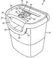
Fig. 1 and 2 shows the perspective view according to the pulverizer of embodiments of the invention structure; Pulverizer usually represents with 10 thatpulverizer 10 is positioned on the waste canister top, and this waste canister is common to be represented and formed by the material of molded plastics or any other with 12.Thepulverizer 10 that illustrates carries out specific design to use withcontainer 12, becausepulverizer shell 14 is positioned on the top periphery ofwaste canister 12 with nest relation.Yetpulverizer 10 also may design so that be positioned on the waste canister top of multiple standards, andpulverizer 10 can not sold with container.Similarly,pulverizer 10 can be the part of big free-standing shell, and waste canister will be enclosed in this shell.Access door will provide container and enter and remove.In general,pulverizer 10 can have any suitable structure or shape, and the embodiment that illustrates is not intended to limit by any way.
Pulverizer 10 comprisesdisintegrating mechanism 16, and it comprisesmotor 18 and a plurality of cutting part (not shown) of electric power." disintegrating mechanism " is general structural term, is used to represent to use the device of cutting part chopping article.This chopping process can adopt any concrete grammar to carry out.Cutting part is installed in (not shown) on the turning cylinder of pair of parallel usually.Motor 18 utilizes electric energy to move with bytraditional transmission device 23 driving shafts and cutting part, thereby makes the cutting part chopping supply with article therein.Disintegrating mechanism 16 also comprises and is used for installation shaft, thesub-frame 21 ofmotor 18 and transmission device 23.The operation of this disintegrating mechanism and structure are well-known, therefore needn't describe in detail at this.Usually, in the prior art or anysuitable disintegrating mechanism 16 of development later on all can use.
Pulverizer 10 also comprises above-mentioned pulverizer shell 14.Pulverizer shell 14 comprises theroof 24 that is positioned oncontainer 12 tops.Thisroof 14 is to be molded by plastic and opening 26 is positioned at itsfront portion.Opening 26 is partly formed by the parts of the common U-shaped of downwarddependence.U-shaped parts 28 have a pair of in thecoupling part 27 that opposite side separates respectively, and with thehandle portion 28 from extending between thecoupling part 27 ofshell 14 difference spaced relationship.The refuse that opening 26 allows to abandon enters in thecontainer 12, and does not passdisintegrating mechanism 16, andparts 28 can serve as the handle that is used to transport the pulverizer of separating fromcontainer 12 10.As optional characteristic, this opening 26 can be equipped with lid, for example rotatable lid, and it can open and close this opening 26.Yet, this opening normally optional and can omit fully.Andpulverizer shell 14 and itsroof 24 can have any suitable structure or shape.
In the illustrated embodiment, switch module connectsmotor 18 to the power supply (not shown).Usually, power supply is the referencepower supply line 44 that has plug 48 in its end, and thisplug 48 inserts in the standard AC socket.By laterally move thispart 46 withingroove 38,switch 42 can move between on-position and open position.Under the on-position situation, the contact of moving in switch module bymanual engagement part 46 and movable part is engaged, thereby electric energy can be sent on the motor 18.Under the situation of open position, the contact in switch module disconnects, and is sent on themotor 18 thereby end electric energy.
As a kind of selection,switch 42 also has backward position, and wherein the contact is engaged, and makes electric energy be transmitted, thereby with reverse manner operation motor 18.Realize by utilizing reversible motor and application to have with respect to the electric current of on-position reversed polarity.Ability with reversemanner operation motor 18 is desirable, thereby blocks reverse mobile cutting part in order to remove.In the illustrated embodiment, under the situation of open position,manual engagement part 46 and moveable part are usually located at the center ofgroove 38, and on backward position the time, they are at the relative transverse side of open position.
Usually, the structure and the operation that are used to control theswitch 42 ofmotor 42 are well-known, and any structure that is used for thisswitch 42 can be used.
Switchlock 52 makesswitch 42 from its on-position or the backward position open position that moves to it by the cam effect, whenswitch lock 52 when the off-position moves to the lock position.Under the situation of off-position, the lock part breaks away from the movable part ofswitch 42, therefore makesswitch 42 connecting, and moves between disconnection and the backward position.Under the situation of lock position, the movable part ofswitch 42 is limited in its open position by the lock part ofswitch lock 52, stops to move in its connection or backward position.
Preferably, yet also optionally, themanual engagement part 54 ofswitch lock 52 has upwardly extendingledge 56, so thatswitch lock 52 moving between locking and off-position.
An advantage ofswitch lock 52 is that at open position, in order to activatedisintegrating mechanism 16,switch lock 52 must at first move on to its off-position by maintainedswitch 42, and switch 42 moves on to its connection or backward position then.This reduces the possibility that disintegrating mechanism is not intended to be activated.
In the illustrated embodiment,pulverizer shell 14 designs particularly using withcontainer 12, and intention is sold them together.The lastcircumferential edges 60 ofcontainer 12 defines towardslast opening 62, and seat 61 is provided, andpulverizer 10 is movably installed on this seat.The a pair ofrotation guiding piece 64 that provides at its relative transverse side is provided seat 61.Rotation guiding piece 64 comprises towardslast groove 66, and it is defined by theupper limb 60 horizontal outward extending walls from container 12.These walls of definition groove 66 form by plastic monoblock ground is molded withcontainer 12, still can provide as separating member and by any other material to form.The bottom of eachgroove 66 provides downward step or ledge, and they provide the surface 68 of common vertical engagement.These are to getting out of a predicament or an embarrassing situation or ledge is produced by two of thegroove 66 that is equipped with different radii parts.
Pulverizer 10 has proximity sensor, to be used to detect the people that approaches opening 36 or the existence of things (for example, animal or lifeless object).When its part outside and approach opening 36, perhaps at least partially within the opening 36 time, then people or things " approaching " opening 36.Proximity sensor can adopt multiple mode to implement, for example below in greater detail.The further example of the pulverizer that uses as proximity sensor, can be to U.S.Patent application 10/828,254 (applications on April 21st, 2004), 10/815,761 (applications on April 2nd, 2004) and 10/347, reference is carried out in 700 (applications on January 22nd, 2003), and each is applied for and is incorporated by reference among the application.Usually, proximity sensor can use with the pulverizer of any kind, and is not intended to limit at this example of determining.
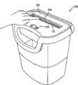
Fig. 3 is the perspective view according to thepulverizer 100 of embodiments of the invention structure.Thispulverizer 100 is in conjunction with capacitance sensor.The capacitance sensor that illustrates is that a kind of people of detection or things exist and do not require the switch of direct contact.Capacitance sensor comprises the conductor/contact plate 112 that is connected on the circuit, for example shown in Fig. 8 and 9.Lead 112 is as first plate of electric capacity, but people to be detected or things are as second polate.When the distance betweenconductor 112 and people or the things reduced, the mutual capacitance between them increased.The electric capacity of these increases causes the signal level that increases in sensor, this level can be used for detecting the degree of approach of people or things.
Be to be understood that capacitance partly relies on the dielectric constant of the second polate of capacitor.Higher dielectric constant is converted into bigger capacitance.Therefore, near the degree of approach that life or abiotic entity arranged of the capacitance sensor ofpulverizer 100 can detecting is if its corresponding dielectric constant is abundant when high.Because people and multiple animal have than higher dielectric constant, they can be detected by capacitance sensor.The lifeless object that has than higher dielectric constant can detect equally.On the contrary, have the object of low or medium dielectric constant, for example paper can not detect.
Pulverizer 100 comprisespulverizer shell 104, and opening 108 and have connection disconnects and thegauge tap 128 of backward position.Disintegrating mechanism, is positioned at below theopening 108, thereby makes document to put in the disintegrating mechanisms by opening 108 by for example above-mentioned one.
Although do not have shown in Figure 3ly,pulverizer 100 can comprise sensor light, the lamp of makeing mistakes, and/or the lamp that runs well of indication.This sensor light can be LED, illuminates when people or things detect.This lamp of makeing mistakes can be LED equally, is illuminated when people or things detect, and selectablely illuminates (for example, shredder container correctly engages withpulverizer 100, and perhaps disintegrating mechanism fills up) in other cases.Yet these lamps are dispensable, only are optional features.
Fig. 4-the 7th, according to a plurality of embodiment of the present invention, each showspulverizer shell 104, opening 108, cuttingelement 132 and the drawing in side sectional elevation that is used for the conductor structure of sensor.Conductor structure can comprise the conductor of zones of different, the capacitance and the signal level that produce during near pulverizer when people or things with finishing.Under the situation that a plurality of conductors use, the distance between them also is designed, to repair the capacitance of capacity coupled quantity and generation.
In Fig. 4,conductor 136 comprises conductive material, its be embedded into the part enter in theopening 108, in the roof of theshell 104 below upper surface.Conductor 136 equally optionally embeds in the wall that definesopening 108 and for a part and extends along it.
In Fig. 5, the upper surface portion of the conductivematerial covering shell 104 ofconductor 140 extends substantially within theopening 108, and centers on the flanges flex ofshell 104, so that the inner surface portion of covering shell 104.For theconductor 140 with significant amount of thickness, the top of the upper surface thatconductor 140 is installed can be by recessed.
Theconductor 144 of Fig. 6 comprises two current-carrying parts of the about surface portion that is respectively fixed to shell 104.The use of this a plurality of parts has increased the surface area of electric capacity, and Capacitance Coupled, capacitance, and the signal level that produces during near current-carrying part when people or things.
Theconductor 148 of Fig. 7 is included in the conductive material on the inner surface portion of shell 104.For example shown in Figure 4, being used for coveringconductor 148 and not increasing embedded conductor is desirable at the manufacturing step of shell wall.The conductor that it will be appreciated that Fig. 4-7 can have any suitable structure, and the example that illustrates never is intended to limit.
About Fig. 3-7, aforesaid conductor or conductive material are typically connected on the circuit on the circuit board.Fig. 8 and 9 shows the capacity sensor circuit according to the example of corresponding embodiment of the present invention.The circuit of example can be incorporated in total circuit design of pulverizer, and never intention limits.
In Fig. 8, capacity sensor circuit 260 comprises conductor 300, and it can have aforesaid structure or another suitable structure.Conductor 300 is connected on the pad P8, and it is connected to subsequently and comprisescapacitor C 8 and C9, and resistor R 31 is on the circuit loop on R32 and R36 and the high speed double diode D8.This loop is connected to voltage supply source Vcc, on circuit ground and the resistance R 33.Voltage supply source Vcc is connected on the alternating current circuit voltage of pulverizer, and the voltage-stabilized power supply of negative electrode can produce-5 volts that are used for circuit ground.Capacitance sensor output 320 is connected on the controller 330 as an input subsequently, for example microprocessor or discrete circuit elements (for example, comparison circuit, transistor), and it takes suitable action with the signal level in response to output 320 subsequently.Sort controller 330 can also be relay switch, and it is opened to end energy and is transported on the parts (for example, the motor of disintegrating mechanism), and closes to allow the conveying of energy.It will be appreciated that " controller " is a common structural term, the one or more modules of its expression control, the member of device and/or circuit block.
The operation principle of circuit 260 can be drawn easily by those skilled in the art.When people or things moved closer in conductor 300, the electric capacity that increases between them caused increasing by the sine-shaped amplitude of voltage at output 320 places, thereby fully represented the existence of people or things.Based on the signal level that increases, controller 330 can, for example, end the cutting part of pulverizer, illuminate sensor or error light, and/or activate the alarm that can hear.
Fig. 9 illustratescapacity sensor circuit 360, and control and lighting circuit 365.Capacity sensor circuit 360 comprisesconductor 400, and it has aforesaid structure or other suitable structure.Conductor 400 is connected to pad P1, and it is connected to series resistance R19 and R20 subsequently.Resistance R 19 is connected to and comprises capacitor C 4, on the circuit loop ofresistance R 16 and high speed double diode D1.This loop is connected to voltage supply source Vcc, on circuit ground and the resistance R 17.Voltage supply source Vcc is connected on the alternating current circuit voltage of pulverizer, and the voltage-stabilized power supply of negative electrode can produce-5 volts that are used for circuit ground.Capacitance sensor output 420 is connected on thecontroller 430 as input, its can for, for example, simple analog circuit or by Atmel company (San Jose, the ATtiny118 8-digit microcontroller that California) provides.
The operation principle of the circuit of Fig. 9 can be drawn by those skilled in the art easily.When people or things moved closer inconductor 400, the electric capacity that increases between them caused increasing by the sine-shaped amplitude of voltage atoutput 420 places, thereby fully represented the existence of people or things.Based on the signal level of this increase,controller 430 sends appropriate control signals.For example,controller 430 490 power supply (for example providing) that removes to be cut to motor, the wherein cutting parts of this Motor Drive pulverizer that transmit control signal by bilateral triode switch.And transmitcontrol signal 435 to illuminate sensor LED450 or the error LED440 that is connected on thecomparison circuit 460.
Embodiments of the invention can be combined in, for example, and in pulverizer, such as Fellowes company (Itasca, pulverizer PS80C-2 Illinois).If required, existing mill structure can be made amendment, and can not carry out main modification to existing module, with in conjunction with near testing circuit.
In another embodiment of the present invention, pulverizer can be provided near the two or more sensitivity devices that detect.These devices can be by the selectable use of user, and adapts to and detect, for example, and baby or pet.Adopt capacitance sensor in the embodiment of example, object is distinguished based on load time.Littler capacitive load causes the load time shorter than big electric capacity.Therefore, by measuring the difference of the load time that (for example, adopting microprocessor) caused by the capacitive load of proximity transducer, many objects can be distinguished.
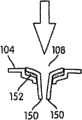
In yet another embodiment of the present invention, the detector of mechanical switch or other type is used for detecting the insertion of exotic.When mechanical switch activated, grinder blade was stopped, and stoped chopping operation (perhaps other operation is implemented).In general, the object that is suitable for shredding be approach with smooth, for example, paper, CD, the dish, credit card or the like.On the other hand, the humans and animals body portion is thicker usually.Therefore, body partly is inserted into the pressure that will cause in the pulverizer opening with respect to the side of opening.For the opening with angled side, this pressure will comprise two parts, and a direction that a part is supplied with by opening at article (vertical usually) and a part are perpendicular to this direction of the supply (common level).By allowing some relative motions of throat sheet, this pressure can be used to activate mechanical switch.The suitable selection of the size by opening and the casting distance of switch (perhaps, when the detector such as the other type of optical switch or deformeter uses, the suitable selection of sensitivity or active detection region), pulverizer can design and not allow any any object greater than preliminary dimension (for example to enter into shredder throat, the size of finger, the size of excessive stack paper for the pulverizer operation), can not activate this switch.Document heap or other the article that can stop up disintegrating mechanism that this structure can also be used to stoping the user to insert excessive thickness.
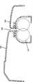
Figure 10 a and 10b illustrate first embodiment of the mechanical switch of use in pulverizer.Shown in Figure 10 a,pulverizer shell 104 comprises opening 108.Thewall 150 ofopening 108 is moveable portion, and it has formed with respect topulverizer shell 104 throat sheet movably.Each of thesewalls 150 has the top of installing against pressuresensitive switch 152, this switch can for, for example, diaphragm switch.Mechanical switch can have, for example, open mode and closed condition, it thinks on-position or off position in addition.
In specific embodiment, diaphragm switch comprises the upwards parts of bias voltage (independently not illustrating), and it helps maintained switch in open mode, and thewall 150 ofbias voltage opening 108 is at their upper position.As shown in the figure, eachwall 150 be independent movably and each have associatedswitch 152, yet, be to be understood that, balanced configuration be not need and one or two wall can have related switch or detector.Similarly, these walls needn't be independently movably, and can move together.
When Figure 10 a illustrated the open position of switch, Figure 10 b illustrates when big relatively object inserts opening 108, and what can take place.When being inserted in theopening 108, it is pressed against on thewall 150, and moves down them when object (with illustrating of arrow signal), compression diaphragm switch 152.The flow process of blocking-up cutting tip is finished in these actions.This system can further reduce because part is blocked in opening, applies the infringement of the pulverizer that the oversize object of a tension force on the cutting motor cause.
Figure 11 a illustrates other alternate embodiments of the present invention.In this embodiment, thewall 150 of opening comprises plunger part 154.Plunger part 154 is applied in thehole 156 in the pulverizer shell 104.This plunger part 154 is passed through upwards bias voltage ofcorresponding spring 158, keeps the upper position ofwall 150 at them.
When big object was inserted in theopening 108, shown in Figure 11 b,wall 150 downward extruding and plunger parts 154 contacted mechanical switch 160.In diagram,switch 160 is lever switch, yet for those of ordinary skills clearly, diaphragm switch or other mechanical switch can replace.Similarly, the deformeter that is used to measure the deflection of member can be used, and the optical pickocff that perhaps is used to detect the position ofwall 150 or other member can be used.Usually, can use the detector of any adequate types.
Figure 10 a, 10b, the embodiment of 11a and 11b each rely on the downward pressure of throat sheet to activate the switch that finishes the chopping operation usually.As mentioned above, the pressure of the big object in the angled wall of insertion opening will help to have horizontal component.Therefore, the pressure plare to the outside motion sensitive of the wall of throat sheet also is suitable for use in the embodiments of the invention.Similarly, though Figure 10 a, 10b, the embodiment of 11a and 11b are described above the cutting tip stopping automatically, and in a selectable structure, activator switch will cause warning indicator, for example activate lamp or sound.Can adopt any this predetermined safe operation.
As selectable in addition, but the bottom of one or twowalls 150 is elastic deflections.This can pass through, and for example, pivotally connects the relative stiffness member and realizes, thereby make its pushing spring, perhaps by adopting the deflectable material of elasticity to make the bar part.Detector can be used for determining when that such as mechanical switch or any other suitabledetector corresponding wall 150 has curved outwardly into to a certain extent.This shows that the article greater than predetermined thickness insert in the opening.Then, implement predetermined operation (for example, cut off disintegrating mechanism, signal gives the alarm).
Figure 12 illustrates the additional embodiments according to switch of the present invention, and Figure 12 a is the zoomed-in view that separates this switch sections.The member of the embodiment of Figure 12 is similar to the member among the embodiment of Fig. 3.Switch 502 can be fixed on theshell 104near opening 108 places.The change that this switch is configured to by resistance detects the contact situation, for example the result who contacts with switch as people's hand.
In an example, switch comprises the grid of conduction, is divided into two contiguous mutually conductors, and this embodiment is communicated with illustrating of control circuit signal in Figure 13.In concrete enforcement, VHi is provided with the 20V less than the nominal of Vcc.Pad P 1 and P2 are provided to the connectedness of the remainder of circuit.Resistance R 3-R6 is selected to have big resistance, thus the electric current by circuit when restriction activates.When user's hand touched grid, this circuit was finished and electric current flows.The aanalogvoltage that expander U1A (its can for, for example, LM358 can be from the semiconductor of country obtains in the heart) buffering produces, and it is sent in the analog input of microprocessor 504.Resistance R 8, R9, R10 can change, so that optionally change the sensitivity of system.
Microprocessor can select to control pulverizer, with the signal that comes in response to expander U1A.Particularly, microprocessor can be provided with and control, bilateral triode switch for example, it controls to the energy of shredder motor subsequently, thus whenswitch 502 contacts blades stop.And as mentioned above, emergency warning lamp or LED can be activated, and why motor is stopped using to notify the user.
Because the all-in resistance ofswitch lattice 502 can change, for example because dirt causes, this signal level can change.Similarly, the user with moist finger will provide the resistance still less than the user with dry fingers.Therefore, in one embodiment, the control software of pulverizer comprises the program along with the time monitoring nominal resistance, and correspondingly regulates threshold value.Similarly, one embodiment of the present of invention allow the change of monitoring aspect signal, rather than the intensity of signal, thereby distinguish between the slow accumulation of dirt and instantaneous contact.At last, in one embodiment, when the measurement nominal resistance is lower than predeterminated level, indicator, for example, LED can be used for notifying this grid of user to clear up.
In another alternate embodiments, switch can be retrofit device.Schematically illustrate as Figure 14, retrofit device is inserted between pulverizer and the power supply.The pulverizer plug is inserted in the controller, rather than directly enters in the power supply of wall.At normal operation period, retrofit device as from the wall outlet to the pulverizer be used for power supply pass through part the time, and when normally inserting in the wall, pulverizer will move basically.Yet, when switch activator, controller, it for example can be, be similar among Figure 13 shown in, can be cut to the indication of the energy and/or the failure condition of pulverizer.
Shown in Figure 15 and 15a,retrofit switch 512 itself is a resistance sensitive switch, and capacitance sensitive switch is perhaps such as the pressure sensitive switch of diaphragm or diaphragm switch.This switch can utilize binding agent or securing member forever or movably to be fixed to the position of adjacent openings 108.It is connected electrically on the controller 514, and this controller 514 separates fully, perhaps only for being fixed to the little packing container on the pulverizer shell.As mentioned above, controller comprises the container 516 of the power line 518 that is used for pulverizer, and generally includes its its own power source line 520 that is used to engage wall outlet 522 or other power supply.
Though the many embodiment that illustrate at this adopt concrete sensor, the approach that should be noted that other can adopt and detect near the people of pulverizer or the existence of things, such as, utilize eddy current, inductance, photoelectricity, ultrasonic wave, the approach of Hall effect or infrared proximity sensor technologies.
The above-mentioned embodiment that illustrates provides and has been provided to show structure of the present invention and principle function, and is not intended to limit.On the contrary, the invention is intended to is to be enclosed in modifications all within the spirit and scope of accessory claim, changes and displacement.
Claims (29)
1. pulverizer, it comprises:
Shell;
Disintegrating mechanism, it is contained in the shell, and comprises the motor and the cutting part of electric power, and this disintegrating mechanism allows article to be shredded to send in the cutting part, and motor is exercisable with the driving cutting part, thereby makes the cutting part chopping supply with article therein;
This shell has elongated, narrow opening, the cutting part of the disintegrating mechanism that makes article enter into to be used for shredding by this opening;
Sensor, it comprises the conducting element that is provided with to contiguous this opening of small part, and be configured to based on the detection of conducting element to the intrinsic electrical characteristics of people or animal, indicate the people that approaches this opening or the existence of animal, wherein, described conducting element is located at relatively vertically between the end and at the longitudinal extension of described opening of this opening, so that the sensor detection range on the whole length of this opening to be provided; With
Controller, it is exercisable, ends disintegrating mechanism with the indication that exists in response to people or animal.
2. pulverizer as claimed in claim 1, wherein said controller is exercisable, to end disintegrating mechanism by stopping to transmit electric power to motor.
3. pulverizer as claimed in claim 1, wherein the scheduled operation existence that is in response to people or animal is indicated and is illuminated an indicator.
4. pulverizer as claimed in claim 1, wherein this controller comprises microcontroller.
5. pulverizer as claimed in claim 1, wherein this sensor is a capacitance sensor.
6. pulverizer as claimed in claim 5, wherein:
This sensor be configured for response since people or animal near the caused capacitance variations of conducting element, the change of indication conducting element state and
Controller is exercisable, changes with the indication in response to the conducting element state and implements described scheduled operation.
7. pulverizer as claimed in claim 6, wherein this conducting element is the thin metal parts that extends along the part of the shell of adjacent openings.
8. pulverizer as claimed in claim 7, wherein this metal parts is arranged on the inner surface of shell.
9. pulverizer as claimed in claim 8, wherein this metal parts only is arranged on the inner surface of shell, rather than on the outer surface.
10. pulverizer as claimed in claim 8, wherein this metal parts also is arranged on the outer surface of shell.
11. pulverizer as claimed in claim 10, this part that the shell of metal parts wherein is set has the edge of a part that limits opening, and on wherein metal parts extends to outer surface on the described edge from the inner surface of shell.
12. pulverizer as claimed in claim 7, wherein this disintegrating mechanism is embedded within the shell.
13. pulverizer as claimed in claim 7, wherein this metal parts is fixed on the described part of shell of adjacent openings at least in part.
14. pulverizer as claimed in claim 13, wherein this metal parts comprises metal tape.
15. pulverizer as claimed in claim 7, wherein this metal parts to small part is covered by non-conductive parts.
16. pulverizer as claimed in claim 15, wherein this non-conductive parts to small part is covered by conductive component.
17. pulverizer as claimed in claim 6, wherein this conducting element to small part comprises on the part that is applied to shell or is applied to metallic paint on the parts relevant with shell.
18. pulverizer as claimed in claim 6, wherein this conducting element comprises at least two metal parts, and each metal parts all extends along the part of the shell of adjacent openings.
19. pulverizer as claimed in claim 1, wherein this controller to small part comprises a microprocessor.
20. pulverizer as claimed in claim 1, wherein this controller to small part comprises discrete circuit elements.
21. pulverizer as claimed in claim 1, wherein this controller to small part comprises an analog circuit.
22. pulverizer as claimed in claim 1, wherein said conducting element extends along the contiguous described opening of the whole length of described opening.
23. pulverizer as claimed in claim 1, wherein said sensor arrangement one-tenth detects human or animal's intrinsic electrical characteristics based on human or animal and contacting of described conducting element.
24. pulverizer as claimed in claim 1, wherein said sensor arrangement become to need not the human or animal to contact the intrinsic electrical characteristics that detect the human or animal with described conducting element.
25. pulverizer as claimed in claim 23, wherein said sensor is an electric resistance sensor.
26. pulverizer as claimed in claim 1, wherein said conducting element are electrodes of capacitor, and described sensor arrangement becomes to detect the mutual capacitance between described conducting element and the human or animal.
27. pulverizer as claimed in claim 1, wherein, the conducting element of sensor elongated open vertically on be elongated.
28. pulverizer as claimed in claim 1, wherein, the conducting element of sensor is along the whole elongate length of elongated open and contiguous this opening extends.
29. pulverizer as claimed in claim 1, wherein,
This elongated, narrow opening is limited by a pair of relative wall;
The conducting element of sensor is linked at least one wall;
The conducting element of sensor extends along at least one wall, and elongation is the whole length of opening basically;
The conducting element of sensor is located on the outer surface of at least one wall, thereby defines described opening at least in part;
The conducting element of sensor is an electrode of capacitor;
Sensor arrangement becomes to detect the mutual capacitance between described conducting element and the human or animal; And
Along with the conducting element of this at least one wall and sensor extends towards cutting part in opening, the conducting element of this at least one wall and sensor is towards the cutting part bending.
Applications Claiming Priority (4)
| Application Number | Priority Date | Filing Date | Title |
|---|---|---|---|
| US10/937,304 | 2004-09-10 | ||
| US10/937,304US7311276B2 (en) | 2004-09-10 | 2004-09-10 | Shredder with proximity sensing system |
| US11/177,480US7661614B2 (en) | 2004-09-10 | 2005-07-11 | Shredder throat safety system |
| US11/177,480 | 2005-07-11 |
Related Parent Applications (1)
| Application Number | Title | Priority Date | Filing Date |
|---|---|---|---|
| CN2005800344785ADivisionCN101180130B (en) | 2004-09-10 | 2005-08-09 | Shredder with throat safety system |
Publications (2)
| Publication Number | Publication Date |
|---|---|
| CN101716545Atrue CN101716545A (en) | 2010-06-02 |
| CN101716545B CN101716545B (en) | 2012-06-27 |
Family
ID=35169695
Family Applications (2)
| Application Number | Title | Priority Date | Filing Date |
|---|---|---|---|
| CN2009102622639AExpired - LifetimeCN101716545B (en) | 2004-09-10 | 2005-08-09 | Shredder throat safety system |
| CN2009102523243AExpired - LifetimeCN101850288B (en) | 2004-09-10 | 2005-08-09 | Pulverizer Throat Safety System |
Family Applications After (1)
| Application Number | Title | Priority Date | Filing Date |
|---|---|---|---|
| CN2009102523243AExpired - LifetimeCN101850288B (en) | 2004-09-10 | 2005-08-09 | Pulverizer Throat Safety System |
Country Status (10)
| Country | Link |
|---|---|
| US (2) | US7661614B2 (en) |
| EP (2) | EP1935497B1 (en) |
| JP (3) | JP2006075831A (en) |
| CN (2) | CN101716545B (en) |
| AU (4) | AU2005285398B2 (en) |
| CA (2) | CA2579137C (en) |
| DE (3) | DE202005021604U1 (en) |
| PL (1) | PL1819442T3 (en) |
| RU (1) | RU2446891C2 (en) |
| WO (1) | WO2006031324A1 (en) |
Families Citing this family (87)
| Publication number | Priority date | Publication date | Assignee | Title |
|---|---|---|---|---|
| WO2004058168A2 (en)* | 2002-12-20 | 2004-07-15 | Dynogen Pharmaceuticals, Inc. | METHODS OF TREATING NON-PAINFUL BLADDER DISORDERS USING α2δ SUBUNIT CALCIUM CHANNEL MODULATORS |
| US8109455B2 (en)* | 2003-10-23 | 2012-02-07 | Buttercup Legacy, Llc | Delivery of agents to the cutting mechanism of paper shredders |
| US7902129B2 (en)* | 2003-10-23 | 2011-03-08 | Buttercup Legacy, Llc | Delivery of agents to the cutting mechanism of paper shredders |
| US7025293B2 (en)* | 2004-04-21 | 2006-04-11 | Fellows Inc. | Shredder with pivoting housing for the shredder mechanism |
| US7631822B2 (en)* | 2004-09-10 | 2009-12-15 | Fellowes Inc. | Shredder with thickness detector |
| US7954737B2 (en) | 2007-10-04 | 2011-06-07 | Fellowes, Inc. | Shredder thickness with anti-jitter feature |
| US7661614B2 (en)* | 2004-09-10 | 2010-02-16 | Fellowes Inc. | Shredder throat safety system |
| US8870106B2 (en)* | 2004-09-10 | 2014-10-28 | Fellowes, Inc. | Shredder with thickness detector |
| US7798435B2 (en)* | 2006-03-22 | 2010-09-21 | Fellowes, Inc. | Shredder with oiling mechanism |
| US7263953B2 (en)* | 2005-03-30 | 2007-09-04 | Krishnamurthy Sundararajan | Automatic pet trainer |
| US8672247B2 (en) | 2005-07-11 | 2014-03-18 | Fellowes, Inc. | Shredder with thickness detector |
| US7303158B1 (en)* | 2006-03-29 | 2007-12-04 | Aron Abramson | Shredder head having shredder blades and an associated safety feature for protecting a portion of a person's body |
| GB2437594B (en)* | 2006-04-24 | 2010-08-11 | Acco Uk Ltd | A shredding machine |
| WO2007137761A1 (en)* | 2006-06-01 | 2007-12-06 | Dahle Bürotechnik Gmbh | Document shredder |
| USD547366S1 (en) | 2006-06-15 | 2007-07-24 | Staples The Office Superstore, Llc | Shredder device |
| CN2915259Y (en)* | 2006-07-14 | 2007-06-27 | 上海震旦办公设备有限公司 | Paper shredder touch safety device |
| US8008812B2 (en) | 2006-07-14 | 2011-08-30 | Aurora Office Equipment Co., Ltd. | Paper shredder control system responsive to touch-sensitive element |
| USD611089S1 (en) | 2006-07-25 | 2010-03-02 | Fellowes, Inc. | Top surface of a shredder |
| DE102006036136A1 (en)* | 2006-07-28 | 2008-01-31 | Martin Yale International Gmbh | Paper shredder i.e. document annihilator, for cutting e.g. paper, has thickness measuring device arranged in area of inlet for measuring thickness of flat material and designed in contactless working manner as capacitive measuring device |
| USD546872S1 (en) | 2006-08-09 | 2007-07-17 | Staples The Office Superstore, Llc | Shredder device |
| JP2008062167A (en)* | 2006-09-06 | 2008-03-21 | Twinbird Corp | Paper shredder and spacer used for this paper shredder |
| JP4925425B2 (en)* | 2006-09-13 | 2012-04-25 | カール事務器株式会社 | Cutting device slot structure |
| US7757982B2 (en)* | 2006-09-28 | 2010-07-20 | Fellowes, Inc. | Shredder with intelligent activation switch |
| JP5149501B2 (en)* | 2006-10-12 | 2013-02-20 | アイリスオーヤマ株式会社 | Shredda |
| CN200957366Y (en) | 2006-10-18 | 2007-10-10 | 东莞市邦泽电子有限公司 | Paper-cutter with multiple inductors |
| US20080093488A1 (en)* | 2006-10-19 | 2008-04-24 | Staples The Office Superstore, Llc | Shredder |
| TWI302479B (en)* | 2006-10-20 | 2008-11-01 | Primax Electronics Ltd | Shredder |
| US20080135655A1 (en)* | 2006-10-25 | 2008-06-12 | Tie Chun Wang | Shutoff mechanism for shredder |
| USD556250S1 (en) | 2006-10-30 | 2007-11-27 | Staples The Office Superstore, Llc | Shredder |
| JP5030539B2 (en)* | 2006-11-07 | 2012-09-19 | カール事務器株式会社 | Shredder slot structure |
| JP2008132407A (en)* | 2006-11-27 | 2008-06-12 | Honda Elesys Co Ltd | Shredder apparatus |
| WO2008094596A2 (en)* | 2007-01-30 | 2008-08-07 | Staples The Office Superstore, Llc | A shredder |
| US7673825B2 (en)* | 2007-03-08 | 2010-03-09 | Gordon Bud Jeansonne | Machine for shredding/collecting drugs and drug packaging incident to permanent disposal |
| US7673822B2 (en)* | 2007-03-12 | 2010-03-09 | Aron Abramson | Shredder head having motor driven shredder blades and an associated safety feature and/or a method of shredding material |
| DE212008000024U1 (en)* | 2007-03-22 | 2009-11-26 | Schwelling, Hermann | Shredder with a safety device at the intake opening |
| DE102007020222B4 (en)* | 2007-04-28 | 2014-03-06 | Hermann Schwelling | paper shredder |
| DE102007020221B4 (en)* | 2007-04-28 | 2014-02-20 | Hermann Schwelling | paper shredder |
| CN201055797Y (en)* | 2007-06-11 | 2008-05-07 | 周小兴 | Circuit apparatus of paper crusher |
| US7757985B2 (en) | 2007-06-27 | 2010-07-20 | Aurora Office Equipment Co., Ltd. | Safety shredder |
| KR100883958B1 (en)* | 2007-06-29 | 2009-02-18 | (주)대진코스탈 | Safety document shredder |
| GB2450932B (en)* | 2007-07-13 | 2009-06-03 | Sean Thomas Hallard | An apparatus, system and method for shredding plasterboard |
| GB2451513B (en) | 2007-08-02 | 2012-04-18 | Acco Uk Ltd | A shredding machine |
| USD586846S1 (en) | 2007-08-31 | 2009-02-17 | Staples The Office Superstore, Llc | Shredder |
| USD587297S1 (en) | 2007-08-31 | 2009-02-24 | Staples The Office Superstore, Llc | Shredder |
| CA2640979C (en) | 2007-10-30 | 2011-03-29 | Liangneng Chen | Safety shredder |
| US20090134253A1 (en)* | 2007-11-28 | 2009-05-28 | Simon Huang | Shredder safety throat |
| USD611088S1 (en) | 2008-02-20 | 2010-03-02 | Staples The Office Superstore, Llc | Shredder |
| CN201239643Y (en) | 2008-08-06 | 2009-05-20 | 上海震旦办公设备有限公司 | Full automatic paper crusher without selecting paper |
| CN201244502Y (en) | 2008-08-19 | 2009-05-27 | 上海震旦办公设备有限公司 | Structure capable of removing nail of automatic paper crusher |
| US8430347B2 (en)* | 2009-01-05 | 2013-04-30 | Fellowes, Inc. | Thickness adjusted motor controller |
| US8201761B2 (en) | 2009-01-05 | 2012-06-19 | Fellowes, Inc. | Thickness sensor based motor controller |
| US8777138B2 (en) | 2009-01-18 | 2014-07-15 | Techtronic Floor Care Technology Limited | Overload fault condition detection system for article destruction device |
| WO2010098599A2 (en)* | 2009-02-25 | 2010-09-02 | 로얄소브린 주식회사 | Automatic paper feed-sensing apparatus for a paper shredder, paper-feeding apparatus comprising same, and paper shredder comprising the automatic paper feed-sensing apparatus and the paper-feeding apparatus |
| CN201380106Y (en) | 2009-02-25 | 2010-01-13 | 青岛皇冠电子有限公司 | Automatic induction device of paper shredder |
| US8091809B2 (en) | 2009-03-24 | 2012-01-10 | Fellowes, Inc. | Shredder with jam proof system |
| CN101543800A (en) | 2009-05-07 | 2009-09-30 | 上海震旦办公设备有限公司 | Paper jamming prevention protective device of paper shredder |
| US8205815B2 (en)* | 2009-05-15 | 2012-06-26 | Fellowes, Inc. | Paper alignment sensor arrangement |
| US8678305B2 (en) | 2009-06-18 | 2014-03-25 | Fellowes, Inc. | Restrictive throat mechanism for paper shredders |
| US8550387B2 (en)* | 2009-06-18 | 2013-10-08 | Tai Hoon K. Matlin | Restrictive throat mechanism for paper shredders |
| US20100327091A1 (en)* | 2009-06-24 | 2010-12-30 | Techko, Inc. | Safety systems and methods for controlling operation of office equipment |
| CN101623664B (en) | 2009-07-31 | 2013-03-20 | 上海震旦办公设备有限公司 | Safety protection device of paper inlet of paper shredder |
| KR101676821B1 (en)* | 2010-03-18 | 2016-11-17 | 삼성전자주식회사 | Magnetic memory device and method of forming the same |
| US8382019B2 (en) | 2010-05-03 | 2013-02-26 | Fellowes, Inc. | In-rush current jam proof sensor control |
| US8511593B2 (en) | 2010-05-28 | 2013-08-20 | Fellowes, Inc. | Differential jam proof sensor for a shredder |
| US8413916B2 (en) | 2010-08-02 | 2013-04-09 | Techtronic Floor Care Technology Limited | Force responsive shredder |
| US9044760B2 (en) | 2010-12-17 | 2015-06-02 | Jeff Buchanan | Wearable safety device for cutting machine |
| US8708260B2 (en) | 2011-08-08 | 2014-04-29 | Aurora Office Equipment Co., Ltd. | Depowered standby paper shredder and method |
| US20130214072A1 (en)* | 2012-02-20 | 2013-08-22 | Tex Year Industries Inc. | Rotary cutter door device for paper shredders |
| US8967510B2 (en) | 2012-09-27 | 2015-03-03 | Aurora Office Equipment Co., Ltd. | Safety shredder |
| US9643190B2 (en) | 2013-03-26 | 2017-05-09 | Aurora Office Equipment Co., Ltd. Shanghai | Safety shredder with bin-full device and time delay |
| EP2759346B1 (en) | 2013-01-26 | 2019-03-13 | Hermann Schwelling | Shredder |
| US10792667B2 (en)* | 2013-09-04 | 2020-10-06 | Herman Chang | Disposable waste system for paper shredder |
| US9827570B2 (en)* | 2015-03-19 | 2017-11-28 | Aurora Office Equipment Co., Ltd. Shanghai | Shredder jam clear apparatus |
| US9687854B2 (en)* | 2015-03-19 | 2017-06-27 | Aurora Office Equipment Co., Ltd. Shanghai | Shredder jam clear apparatus |
| US10639642B2 (en)* | 2015-03-19 | 2020-05-05 | Aurora Office Equipment Co., Ltd. Shanghai | Shredder jam clear apparatus |
| US10537898B1 (en)* | 2015-04-20 | 2020-01-21 | SMT Medical Technologies, LLC | Device and method for processing solid waste material |
| JP2017104884A (en)* | 2015-12-09 | 2017-06-15 | 株式会社Tds | Volume reduction machine |
| US10480962B2 (en)* | 2017-04-21 | 2019-11-19 | Capsule Technologies, Inc. | Electronic device including a capacitive sensor in a housing |
| WO2019077392A1 (en)* | 2017-10-19 | 2019-04-25 | TOMS, Shaun Ivanhoe | Sensing means and method |
| US10842080B2 (en)* | 2017-10-27 | 2020-11-24 | Eteros Technologies Inc. | Plant trimming apparatus and methods |
| US12058964B2 (en) | 2017-10-27 | 2024-08-13 | Eteros Technologies Inc. | Plant trimming apparatus and methods |
| CN110170360B (en)* | 2019-05-31 | 2021-04-13 | 浙江理工大学 | A kind of paper shredder and its shredding method |
| CN110180644B (en)* | 2019-05-31 | 2021-04-27 | 浙江理工大学 | A kind of paper shredder and its shredding method |
| DE102019126978A1 (en)* | 2019-10-08 | 2021-04-08 | Kleemann Gmbh | Rock processing machine with improved control panel |
| CN112371280A (en)* | 2020-10-23 | 2021-02-19 | 章苏燕 | Recovery unit is smashed to express delivery carton |
| CN113351328A (en)* | 2021-05-20 | 2021-09-07 | 广东邦泽创科电器股份有限公司 | Paper shredder with dual protection function |
| US20230278042A1 (en) | 2022-03-02 | 2023-09-07 | Fellowes, Inc. | Lubricant sheet for a shredder |
Family Cites Families (180)
| Publication number | Priority date | Publication date | Assignee | Title |
|---|---|---|---|---|
| US268244A (en)* | 1882-11-28 | Stove-pipe shelf | ||
| US562076A (en)* | 1896-06-16 | Molder s screen | ||
| US1177832A (en)* | 1915-03-22 | 1916-04-04 | Harold Sage Truscott | Method of handling sugar-cane juices. |
| US1199903A (en)* | 1916-02-19 | 1916-10-03 | Arthur Neal Kerr | Refining method and apparatus. |
| US2022566A (en)* | 1935-03-27 | 1935-11-26 | Inman Mfg Company Inc | Fruit basket |
| US2171029A (en)* | 1937-02-02 | 1939-08-29 | Geldhof Silver | Pneumatic tool |
| US2221516A (en) | 1937-04-01 | 1940-11-12 | Gen Electric | Continuous thickness gauge |
| US2209963A (en)* | 1938-06-18 | 1940-08-06 | California Inst Of Techn | X-ray generating device |
| US2451513A (en)* | 1938-08-17 | 1948-10-19 | Salomon Francois Marie Bernard | Oscillation reducing device |
| US2442942A (en)* | 1941-09-11 | 1948-06-08 | Distillers Co Yeast Ltd | Recovery of acetaldehyde from gaseous mixtures containing the same |
| US2440651A (en)* | 1943-09-18 | 1948-04-27 | Continental Oil Co | Tool joint |
| GB1199903A (en) | 1969-01-10 | 1970-07-22 | Acral Ltd | Shredding Machine |
| JPS5311911Y1 (en)* | 1970-05-25 | 1978-03-31 | ||
| US3619537A (en) | 1970-10-12 | 1971-11-09 | Matsushita Electric Industrial Co Ltd | High-frequency heating device |
| CH548698A (en)* | 1971-03-16 | 1974-04-30 | Mueller Harro | CIRCUIT ARRANGEMENT FOR EMISSION OF AN APPROXIMATION SIGNAL WHEN APPROACHING A HUMAN BODY PART. |
| US3724766A (en) | 1971-05-14 | 1973-04-03 | Ketcham & Mcdougall | Shredder |
| US3829850A (en)* | 1971-12-17 | 1974-08-13 | Tyco Laboratories Inc | Proximity detector |
| US3829580A (en)* | 1972-04-24 | 1974-08-13 | Rohm & Haas | Fungicidal dithiomalonamides and their congeners |
| US3785230A (en)* | 1972-11-08 | 1974-01-15 | Lokey Tool Inc | Automatic safety brake for rotary blade equipment |
| US3947734A (en)* | 1974-09-06 | 1976-03-30 | The Stanley Works | Electronic personnel safety sensor |
| JPS5211691U (en)* | 1975-07-14 | 1977-01-27 | ||
| JPS6039165B2 (en)* | 1976-06-24 | 1985-09-04 | ミノルタ株式会社 | Exposure information setting circuit |
| JPS55140982A (en)* | 1979-04-20 | 1980-11-04 | Laurel Bank Mach Co Ltd | Soundproof device for paper counting machine |
| JPS5814992Y2 (en)* | 1980-10-23 | 1983-03-25 | 株式会社岡村製作所 | Shredder safety device |
| DE3234746A1 (en)* | 1982-09-20 | 1984-03-22 | Agfa-Gevaert Ag, 5090 Leverkusen | SORTING COPY TRAY |
| US4495456A (en) | 1982-09-23 | 1985-01-22 | General Binding Corporation | Automatic reversing system for shredder |
| US5186398A (en)* | 1982-09-30 | 1993-02-16 | Paul E. Vigneaux, Jr. | Paper shredder |
| JPS59150554A (en)* | 1983-02-18 | 1984-08-28 | 富士ゼロックス株式会社 | Paper shredding apparatus |
| US4489897A (en) | 1983-03-02 | 1984-12-25 | General Binding Corporation | Apparatus for shredding documents |
| DE3312991C2 (en)* | 1983-04-12 | 1987-04-23 | Feinwerktechnik Schleicher & Co, 7778 Markdorf | Device for shredding materials such as documents etc. |
| DE3313232A1 (en) | 1983-04-13 | 1984-10-18 | Geha-Werke Gmbh, 3000 Hannover | Cover flap for the paper inlet of an office machine |
| US4757949A (en)* | 1983-08-04 | 1988-07-19 | Horton Norman P | Apparatus for shredding rubber tires |
| FR2553299A1 (en)* | 1983-10-14 | 1985-04-19 | Bonnet Ets | APPARATUS FOR FOOD INDUSTRIES WITH ACCESS CONTROLLED BY A DEVICE CREATING A VARIATION IN ELECTRIC IMPEDANCE |
| JPS61702A (en)* | 1984-06-14 | 1986-01-06 | Sumitomo Electric Ind Ltd | Plane contact sensor |
| DE3505074C2 (en) | 1985-02-14 | 1987-04-16 | Alois Zettler Elektrotechnische Fabrik GmbH, 8000 München | Housing for device for destroying sheet material |
| US4707704A (en) | 1986-05-09 | 1987-11-17 | Advanced Color Technology, Inc. | Control system and method for handling sheet materials |
| JPS62183555U (en)* | 1986-05-13 | 1987-11-21 | ||
| DE8619856U1 (en)* | 1986-07-24 | 1988-09-08 | Feinwerktechnik Schleicher & Co, 7778 Markdorf | Safety device on waste disposal machines |
| EP0299541B1 (en)* | 1986-11-20 | 1991-05-08 | Ernst Peiniger GmbH Unternehmen für Bautenschutz | Safety device for an operator-controlled apparatus |
| DE3780024T2 (en) | 1987-01-13 | 1992-12-24 | Sharp Kk | TORNING MACHINE. |
| US5320335A (en)* | 1987-08-07 | 1994-06-14 | Canon Kabushiki Kaisha | Control method for sheet discharger with stapler method of stapling a group a discharged sheets into sub-groups having up to n sheets |
| GB8722063D0 (en) | 1987-09-18 | 1987-10-28 | De La Rue Syst | Shredding sheets |
| SU1756148A1 (en)* | 1990-03-30 | 1992-08-23 | Научно-Производственная Организация Внедрения Перспективных Разработок И Патентно-Информационных Исследований "Инновация" | Control device of feeding sheet blanks |
| US5017972A (en)* | 1990-05-30 | 1991-05-21 | Xerox Corporation | Elevator tray position control apparatus |
| US5081406A (en)* | 1990-06-26 | 1992-01-14 | Saf-T-Margin, Inc. | Proximity responsive capacitance sensitive method, system, and associated electrical circuitry for use in controlling mechanical and electro-mechanical equipment |
| JP2610542B2 (en)* | 1990-07-16 | 1997-05-14 | 日本信号株式会社 | Work safety system configuration method |
| JPH0568907A (en)* | 1991-03-13 | 1993-03-23 | Riso Kagaku Corp | Paper sheet data disposal treatment apparatus |
| US5166679A (en) | 1991-06-06 | 1992-11-24 | The United States Of America As Represented By The Administrator Of The National Aeronautics & Space Administration | Driven shielding capacitive proximity sensor |
| DE4121330A1 (en) | 1991-06-28 | 1993-01-14 | Schleicher & Co Int | Document shredding machine - has intake side and conveyor with openings to accept goods with limiting gap and safety device to protect against damage. |
| DE69211647T2 (en)* | 1991-10-17 | 1997-01-02 | Philips Electronics Nv | Remote control circuit with a capacitive sensor for a hose handle |
| GB2258922A (en)* | 1991-10-17 | 1993-02-24 | Philips Nv | Power supply circuit for personal-care apparatus. |
| US5397890A (en)* | 1991-12-20 | 1995-03-14 | Schueler; Robert A. | Non-contact switch for detecting the presence of operator on power machinery |
| JP2531011Y2 (en)* | 1991-12-25 | 1997-04-02 | 松下電器産業株式会社 | Cutting machine |
| DE4212151A1 (en)* | 1992-04-10 | 1993-10-14 | Gao Ges Automation Org | Process for monitoring the function of mechanical paper shredders |
| DE4408470C2 (en)* | 1993-03-22 | 1995-07-20 | Hermann Schwelling | Document shredder with cabinet-like base and hood-like attachment |
| JPH06277548A (en)* | 1993-03-23 | 1994-10-04 | Ricoh Elemex Corp | Paper feed device of shredder |
| CA2095398C (en)* | 1993-05-03 | 2001-06-12 | Kalyan Ghosh | System for detecting human presence in hazardous situations |
| JP3303448B2 (en)* | 1993-08-02 | 2002-07-22 | 松下電器産業株式会社 | Shredder |
| JP3202482B2 (en)* | 1994-05-10 | 2001-08-27 | リコーエレメックス株式会社 | Shredder paper feeder |
| US5494229A (en)* | 1994-08-19 | 1996-02-27 | Cummins-Allison Corp. | Paper shredder with an improved lubrication system and method of lubricating |
| JP3095114B2 (en) | 1994-08-31 | 2000-10-03 | リコーエレメックス株式会社 | Paper feeder for shredder and paper feed method using the same |
| JPH0975763A (en)* | 1995-09-14 | 1997-03-25 | Matsushita Electric Ind Co Ltd | Document shredder |
| EP0850385B1 (en)* | 1995-09-25 | 2002-10-02 | Jorn Sorensen | A method and a device for sensing the distance between a first object and a second object |
| US5823529A (en)* | 1995-10-05 | 1998-10-20 | Xerox Corporation | Single stack height sensor for plural sheet stacking bins system |
| JPH1048344A (en)* | 1996-08-05 | 1998-02-20 | Sumitomo Chem Co Ltd | Sensors and safety devices |
| US5850342A (en) | 1996-09-24 | 1998-12-15 | Nakamura; Kaoru | Machine tool control system |
| US5924637A (en) | 1997-04-16 | 1999-07-20 | Niederholtmeyer; Werner | Oversize tire and rubber debris shredder |
| TW320997U (en) | 1997-04-09 | 1997-11-21 | Shao-Nong Tsai | Switch of shredder |
| DE19717918C2 (en)* | 1997-04-28 | 2000-04-27 | Hermann Schwelling | Safety switch for shredders |
| DE19835093A1 (en) | 1997-07-25 | 1999-02-25 | Fellowes Mfg Co | Paper shredder with DC motor |
| JPH11132396A (en)* | 1997-10-31 | 1999-05-21 | Sumitomo Chem Co Ltd | Sensors and safety devices |
| US5988542A (en) | 1998-05-18 | 1999-11-23 | General Binding Corporation | Document shredding devices |
| USD414198S (en)* | 1998-05-29 | 1999-09-21 | Iwataryo Co., Ltd. | Manual shredder |
| USD412716S (en)* | 1998-06-30 | 1999-08-10 | Fellowes Manufacturing Company | Paper shredder |
| US6079645A (en)* | 1998-09-15 | 2000-06-27 | General Binding Corporation | Desktop shredders |
| USD426805S (en)* | 1998-09-30 | 2000-06-20 | Iwataryo Co., Ltd. | Manual shredder |
| KR100292502B1 (en)* | 1998-11-07 | 2001-07-12 | 구자홍 | Touch switch and method for fabricating electrified layer therof |
| AUPP743998A0 (en)* | 1998-12-02 | 1998-12-24 | Gust, Mark William | Wood chipper safety system |
| TW424582U (en)* | 1998-12-31 | 2001-03-01 | Tsai Shau Nung | Paper shredder with dual functions |
| KR100640033B1 (en) | 1999-02-16 | 2006-10-31 | 가부시키가이샤메이코쇼카이 | Shredder drive control device and drive control method |
| JP3972064B2 (en)* | 1999-04-02 | 2007-09-05 | 独立行政法人労働安全衛生総合研究所 | Sensor device and safety device |
| US6536536B1 (en)* | 1999-04-29 | 2003-03-25 | Stephen F. Gass | Power tools |
| JP2001065789A (en)* | 1999-08-25 | 2001-03-16 | Sumitomo Chem Co Ltd | Sensors and safety devices |
| MXPA02003291A (en) | 1999-09-30 | 2004-09-10 | Gregory J Peterson | Artificial firelog and firestarter chip producing apparatus and method and products produced therefrom. |
| US7536238B2 (en)* | 2003-12-31 | 2009-05-19 | Sd3, Llc | Detection systems for power equipment |
| US7308843B2 (en)* | 2000-08-14 | 2007-12-18 | Sd3, Llc | Spring-biased brake mechanism for power equipment |
| US7171879B2 (en)* | 2001-07-02 | 2007-02-06 | Sd3, Llc | Discrete proximity detection system |
| US6877410B2 (en)* | 2000-09-29 | 2005-04-12 | Sd3, Llc | Miter saw with improved safety system |
| US7712403B2 (en)* | 2001-07-03 | 2010-05-11 | Sd3, Llc | Actuators for use in fast-acting safety systems |
| US20020017179A1 (en)* | 2000-08-14 | 2002-02-14 | Gass Stephen F. | Miter saw with improved safety system |
| US7000514B2 (en)* | 2001-07-27 | 2006-02-21 | Sd3, Llc | Safety systems for band saws |
| US7231856B2 (en) | 2001-06-13 | 2007-06-19 | Sd3, Llc | Apparatus and method for detecting dangerous conditions in power equipment |
| US6957601B2 (en)* | 2000-08-14 | 2005-10-25 | Sd3, Llc | Translation stop for use in power equipment |
| US6994004B2 (en)* | 2000-09-29 | 2006-02-07 | Sd3, Llc | Table saw with improved safety system |
| US20050139459A1 (en)* | 2003-12-31 | 2005-06-30 | Gass Stephen F. | Switch box for power tools with safety systems |
| US20020056349A1 (en)* | 2000-09-29 | 2002-05-16 | Gass Stephen F. | Miter saw with improved safety system |
| US7024975B2 (en)* | 2000-08-14 | 2006-04-11 | Sd3, Llc | Brake mechanism for power equipment |
| US7350445B2 (en)* | 2003-08-20 | 2008-04-01 | Sd3, Llc | Brake cartridge for power equipment |
| US6880440B2 (en)* | 2000-09-29 | 2005-04-19 | Sd3, Llc | Miter saw with improved safety system |
| US7225712B2 (en)* | 2000-08-14 | 2007-06-05 | Sd3, Llc | Motion detecting system for use in a safety system for power equipment |
| US7600455B2 (en)* | 2000-08-14 | 2009-10-13 | Sd3, Llc | Logic control for fast-acting safety system |
| US9927796B2 (en) | 2001-05-17 | 2018-03-27 | Sawstop Holding Llc | Band saw with improved safety system |
| US8061245B2 (en)* | 2000-09-29 | 2011-11-22 | Sd3, Llc | Safety methods for use in power equipment |
| US7098800B2 (en)* | 2003-03-05 | 2006-08-29 | Sd3, Llc | Retraction system and motor position for use with safety systems for power equipment |
| US9724840B2 (en) | 1999-10-01 | 2017-08-08 | Sd3, Llc | Safety systems for power equipment |
| US7509899B2 (en)* | 2000-08-14 | 2009-03-31 | Sd3, Llc | Retraction system for use in power equipment |
| US7827890B2 (en)* | 2004-01-29 | 2010-11-09 | Sd3, Llc | Table saws with safety systems and systems to mount and index attachments |
| US6857345B2 (en)* | 2000-08-14 | 2005-02-22 | Sd3, Llc | Brake positioning system |
| US7707920B2 (en)* | 2003-12-31 | 2010-05-04 | Sd3, Llc | Table saws with safety systems |
| US20030037651A1 (en)* | 2001-08-13 | 2003-02-27 | Gass Stephen F. | Safety systems for power equipment |
| US7284467B2 (en)* | 2000-08-14 | 2007-10-23 | Sd3, Llc | Apparatus and method for detecting dangerous conditions in power equipment |
| US20030140749A1 (en) | 2002-01-25 | 2003-07-31 | Gass Stephen F. | Brake Pawls for power equipment |
| US6945149B2 (en)* | 2001-07-25 | 2005-09-20 | Sd3, Llc | Actuators for use in fast-acting safety systems |
| US20030056853A1 (en)* | 2001-09-21 | 2003-03-27 | Gass Stephen F. | Router with improved safety system |
| US20040040426A1 (en)* | 2002-08-27 | 2004-03-04 | Gass Stephen F. | Miter saw with improved safety system |
| US20030131703A1 (en)* | 2002-01-16 | 2003-07-17 | Gass Stephen F. | Apparatus and method for detecting dangerous conditions in power equipment |
| US7472634B2 (en)* | 2003-08-20 | 2009-01-06 | Sd3, Llc | Woodworking machines with overmolded arbors |
| US20030015253A1 (en)* | 2001-07-18 | 2003-01-23 | Gass Stephen F. | Router with improved safety system |
| US20050139056A1 (en)* | 2003-12-31 | 2005-06-30 | Gass Stephen F. | Fences for table saws |
| US6920814B2 (en)* | 2000-08-14 | 2005-07-26 | Sd3, Llc | Cutting tool safety system |
| US7610836B2 (en)* | 2000-08-14 | 2009-11-03 | Sd3, Llc | Replaceable brake mechanism for power equipment |
| US20050041359A1 (en)* | 2003-08-20 | 2005-02-24 | Gass Stephen F. | Motion detecting system for use in a safety system for power equipment |
| US7350444B2 (en) | 2000-08-14 | 2008-04-01 | Sd3, Llc | Table saw with improved safety system |
| US7077039B2 (en)* | 2001-11-13 | 2006-07-18 | Sd3, Llc | Detection system for power equipment |
| US7197969B2 (en)* | 2001-09-24 | 2007-04-03 | Sd3, Llc | Logic control with test mode for fast-acting safety system |
| US7137326B2 (en) | 2000-08-14 | 2006-11-21 | Sd3, Llc | Translation stop for use in power equipment |
| US8459157B2 (en)* | 2003-12-31 | 2013-06-11 | Sd3, Llc | Brake cartridges and mounting systems for brake cartridges |
| US7377199B2 (en)* | 2000-09-29 | 2008-05-27 | Sd3, Llc | Contact detection system for power equipment |
| US7100483B2 (en)* | 2000-08-14 | 2006-09-05 | Sd3, Llc | Firing subsystem for use in a fast-acting safety system |
| US6945148B2 (en) | 2000-09-29 | 2005-09-20 | Sd3, Llc | Miter saw with improved safety system |
| US7210383B2 (en)* | 2000-08-14 | 2007-05-01 | Sd3, Llc | Detection system for power equipment |
| JP2001137730A (en)* | 1999-11-17 | 2001-05-22 | Meiko Shokai Co Ltd | Shredder having door lock means |
| JP4644973B2 (en)* | 2000-06-01 | 2011-03-09 | マックス株式会社 | Electric stapler |
| US6724324B1 (en)* | 2000-08-21 | 2004-04-20 | Delphi Technologies, Inc. | Capacitive proximity sensor |
| JP2002066978A (en)* | 2000-08-24 | 2002-03-05 | Sharp Corp | Human-friendly robot |
| US6601787B1 (en) | 2000-08-31 | 2003-08-05 | Bertwin Langenecker | Method and an apparatus for managing contaminated material |
| US6813983B2 (en)* | 2000-09-29 | 2004-11-09 | Sd3, Llc | Power saw with improved safety system |
| US6826988B2 (en)* | 2000-09-29 | 2004-12-07 | Sd3, Llc | Miter saw with improved safety system |
| US6819242B2 (en)* | 2000-10-02 | 2004-11-16 | Invisa, Inc. | Apparatus for use with capacitive presence detection systems |
| US6550701B1 (en) | 2000-10-10 | 2003-04-22 | Frank Chang | Dual-functional medium shredding machine structure |
| JP4836332B2 (en) | 2001-01-16 | 2011-12-14 | 三菱電機株式会社 | Motor control circuit for document shredder |
| JP2002239405A (en) | 2001-02-22 | 2002-08-27 | Nakabayashi Co Ltd | Charging port for material to be shredded in shredder |
| US6676460B1 (en)* | 2001-07-05 | 2004-01-13 | Maruta Electric Boatworks Llc | Electronic propeller guard |
| US6979813B2 (en)* | 2001-11-21 | 2005-12-27 | Avril John G | Safety-shutoff device for a manually fed processing machine |
| US7607598B2 (en) | 2001-12-26 | 2009-10-27 | Castronovo Charles A | Self-healing cutting apparatus and other self-healing machinery |
| JP2004141854A (en)* | 2002-08-28 | 2004-05-20 | Fuji Xerox Co Ltd | Shredder apparatus and shredding method |
| US6983903B2 (en) | 2003-01-22 | 2006-01-10 | Fellowes, Inc. | Multi-functional shredder |
| US7698975B2 (en)* | 2003-01-31 | 2010-04-20 | Techtronic Power Tools Technology Limited | Table saw with cutting tool retraction system |
| US20040194594A1 (en)* | 2003-01-31 | 2004-10-07 | Dils Jeffrey M. | Machine safety protection system |
| JP2004321993A (en) | 2003-04-25 | 2004-11-18 | Ishizawa Seisakusho:Kk | Feeding port for document to be shredded in document shredder |
| US6922153B2 (en) | 2003-05-13 | 2005-07-26 | Credo Technology Corporation | Safety detection and protection system for power tools |
| US8109455B2 (en)* | 2003-10-23 | 2012-02-07 | Buttercup Legacy, Llc | Delivery of agents to the cutting mechanism of paper shredders |
| US7166561B2 (en)* | 2003-10-23 | 2007-01-23 | Buttercup Legacy, Llc | Lubricant-carrying substrate for maintenance of paper shredders |
| US7902129B2 (en)* | 2003-10-23 | 2011-03-08 | Buttercup Legacy, Llc | Delivery of agents to the cutting mechanism of paper shredders |
| DE202004000907U1 (en) | 2004-01-22 | 2005-05-25 | Krug & Priester Gmbh & Co. Kg. | Crushing device, in particular shredder |
| US7040559B2 (en)* | 2004-04-02 | 2006-05-09 | Fellowes Inc. | Shredder with lock for on/off switch |
| US7025293B2 (en) | 2004-04-21 | 2006-04-11 | Fellows Inc. | Shredder with pivoting housing for the shredder mechanism |
| US7600705B2 (en)* | 2004-07-26 | 2009-10-13 | Castronovo Charles A | Feeding mechanism auto-adjusting to load for use in automatic high-security destruction of a mixed load, and other feeding systems |
| US7954737B2 (en) | 2007-10-04 | 2011-06-07 | Fellowes, Inc. | Shredder thickness with anti-jitter feature |
| US7798435B2 (en) | 2006-03-22 | 2010-09-21 | Fellowes, Inc. | Shredder with oiling mechanism |
| US7631822B2 (en) | 2004-09-10 | 2009-12-15 | Fellowes Inc. | Shredder with thickness detector |
| US7661614B2 (en) | 2004-09-10 | 2010-02-16 | Fellowes Inc. | Shredder throat safety system |
| US7311276B2 (en) | 2004-09-10 | 2007-12-25 | Fellowes Inc. | Shredder with proximity sensing system |
| WO2006036370A2 (en) | 2004-09-27 | 2006-04-06 | David Pierce | Lubricating system for shredders |
| US7195185B2 (en)* | 2004-11-02 | 2007-03-27 | Fellowes, Inc. | Shredder with separate waste opening |
| WO2006074122A1 (en) | 2005-01-04 | 2006-07-13 | Fellowes, Inc. | Shredder with stack thickness gauge |
| US20060243631A1 (en) | 2005-04-20 | 2006-11-02 | Duke Derek A | Method and apparatus for lubricating a shredding device |
| US7483424B2 (en) | 2005-07-28 | 2009-01-27 | International Business Machines Corporation | Method, for securely maintaining communications network connection data |
| US20070080252A1 (en)* | 2005-08-19 | 2007-04-12 | Seanet Development, Inc. | Shredder maintenance material delivery system |
| CN100389883C (en) | 2006-01-17 | 2008-05-28 | 钟奋强 | Intelligent shift shredding mechanism and its automatic shift method |
| GB2437594B (en) | 2006-04-24 | 2010-08-11 | Acco Uk Ltd | A shredding machine |
| DE102007020159A1 (en) | 2006-04-27 | 2007-12-27 | Hirschmann Automotive Gmbh | Hall-based sensor assembly designed to measure linear motion |
| DE102006036136A1 (en) | 2006-07-28 | 2008-01-31 | Martin Yale International Gmbh | Paper shredder i.e. document annihilator, for cutting e.g. paper, has thickness measuring device arranged in area of inlet for measuring thickness of flat material and designed in contactless working manner as capacitive measuring device |
| TWI302479B (en) | 2006-10-20 | 2008-11-01 | Primax Electronics Ltd | Shredder |
| TWI325790B (en) | 2007-07-27 | 2010-06-11 | Primax Electronics Ltd | Floating detection device for measuring the thickness of a sheet-like article |
| GB2451513B (en) | 2007-08-02 | 2012-04-18 | Acco Uk Ltd | A shredding machine |
| US7663769B2 (en) | 2007-09-27 | 2010-02-16 | Kabushiki Kaisha Toshiba | Sheet thickness measuring device and image forming apparatus |
| TWI346002B (en) | 2008-12-01 | 2011-08-01 | Primax Electronics Ltd | Shredder with detecting mechanism for width and thickness of shredded object |
| US8201761B2 (en) | 2009-01-05 | 2012-06-19 | Fellowes, Inc. | Thickness sensor based motor controller |
| US8430347B2 (en) | 2009-01-05 | 2013-04-30 | Fellowes, Inc. | Thickness adjusted motor controller |
- 2005
- 2005-07-11USUS11/177,480patent/US7661614B2/enactiveActive
- 2005-08-09WOPCT/US2005/028290patent/WO2006031324A1/enactiveSearch and Examination
- 2005-08-09DEDE202005021604Upatent/DE202005021604U1/ennot_activeExpired - Lifetime
- 2005-08-09PLPL05784240Tpatent/PL1819442T3/enunknown
- 2005-08-09AUAU2005285398Apatent/AU2005285398B2/ennot_activeExpired
- 2005-08-09CACA2579137Apatent/CA2579137C/ennot_activeExpired - Lifetime
- 2005-08-09CACA2683280Apatent/CA2683280C/ennot_activeExpired - Lifetime
- 2005-08-09EPEP08102126.3Apatent/EP1935497B1/ennot_activeExpired - Lifetime
- 2005-08-09CNCN2009102622639Apatent/CN101716545B/ennot_activeExpired - Lifetime
- 2005-08-09DEDE202005021676Upatent/DE202005021676U1/ennot_activeExpired - Lifetime
- 2005-08-09DEDE202005021450Upatent/DE202005021450U1/ennot_activeExpired - Lifetime
- 2005-08-09CNCN2009102523243Apatent/CN101850288B/ennot_activeExpired - Lifetime
- 2005-08-09EPEP05784240.3Apatent/EP1819442B1/ennot_activeExpired - Lifetime
- 2005-09-09JPJP2005261612Apatent/JP2006075831A/enactivePending
- 2006
- 2006-12-25JPJP2006347558Apatent/JP4653066B2/ennot_activeExpired - Lifetime
- 2008
- 2008-02-27AUAU2008100182Apatent/AU2008100182B4/ennot_activeExpired
- 2008-06-05AUAU2008202504Apatent/AU2008202504B2/ennot_activeExpired
- 2009
- 2009-09-11RURU2009134476/13Apatent/RU2446891C2/enactiveIP Right Revival
- 2009-12-03USUS12/630,488patent/US7946515B2/ennot_activeExpired - Lifetime
- 2009-12-28JPJP2009298593Apatent/JP5330987B2/ennot_activeExpired - Lifetime
- 2010
- 2010-01-19AUAU2010100056Apatent/AU2010100056B4/ennot_activeExpired
Also Published As
Similar Documents
| Publication | Publication Date | Title |
|---|---|---|
| CN101716545A (en) | Shredder throat safety system | |
| CN101180130B (en) | Shredder with throat safety system | |
| US7475837B2 (en) | Shredder head having shredder blades and an associated safety feature for protecting a portion of a person's body | |
| US7757982B2 (en) | Shredder with intelligent activation switch | |
| US8754552B2 (en) | Permittivity-based paper shredder control system | |
| US7309840B1 (en) | Emergency stopping safety device of paper shredder | |
| RU2379111C2 (en) | Shredder with safe mouth | |
| CN1887428A (en) | Safe shredder | |
| CN2928244Y (en) | Safety paper shredder | |
| KR900003428Y1 (en) | Top lid opening and closing detection device of document shredder | |
| WO2008116350A1 (en) | A safety paper-shredder and its paper-inlet tactile sensing device | |
| US20100176228A1 (en) | Safety switch of a shredder |
Legal Events
| Date | Code | Title | Description |
|---|---|---|---|
| C06 | Publication | ||
| PB01 | Publication | ||
| C10 | Entry into substantive examination | ||
| SE01 | Entry into force of request for substantive examination | ||
| ASS | Succession or assignment of patent right | Owner name:BANK SAFETY DEPOSIT BOX COMPANY Free format text:FORMER OWNER: FELLOWES INC. Effective date:20101213 | |
| C41 | Transfer of patent application or patent right or utility model | ||
| COR | Change of bibliographic data | Free format text:CORRECT: ADDRESS; FROM: ILLINOIS, UNITED STATES TO: ILLINOIS STATE, UNITED STATES | |
| TA01 | Transfer of patent application right | Effective date of registration:20101213 Address after:Illinois, USA Applicant after:FELLOWES, Inc. Address before:Illinois Instrunment Applicant before:Fila Corp. | |
| C14 | Grant of patent or utility model | ||
| GR01 | Patent grant | ||
| CX01 | Expiry of patent term | ||
| CX01 | Expiry of patent term | Granted publication date:20120627 |