CN101714898A - Illumination light communication device - Google Patents
Illumination light communication deviceDownload PDFInfo
- Publication number
- CN101714898A CN101714898ACN200910179120ACN200910179120ACN101714898ACN 101714898 ACN101714898 ACN 101714898ACN 200910179120 ACN200910179120 ACN 200910179120ACN 200910179120 ACN200910179120 ACN 200910179120ACN 101714898 ACN101714898 ACN 101714898A
- Authority
- CN
- China
- Prior art keywords
- light
- information
- communication
- illumination
- lighting
- Prior art date
- Legal status (The legal status is an assumption and is not a legal conclusion. Google has not performed a legal analysis and makes no representation as to the accuracy of the status listed.)
- Pending
Links
Images


Classifications
- H—ELECTRICITY
- H04—ELECTRIC COMMUNICATION TECHNIQUE
- H04B—TRANSMISSION
- H04B10/00—Transmission systems employing electromagnetic waves other than radio-waves, e.g. infrared, visible or ultraviolet light, or employing corpuscular radiation, e.g. quantum communication
- H04B10/11—Arrangements specific to free-space transmission, i.e. transmission through air or vacuum
- H04B10/114—Indoor or close-range type systems
- H04B10/116—Visible light communication
- F—MECHANICAL ENGINEERING; LIGHTING; HEATING; WEAPONS; BLASTING
- F21—LIGHTING
- F21S—NON-PORTABLE LIGHTING DEVICES; SYSTEMS THEREOF; VEHICLE LIGHTING DEVICES SPECIALLY ADAPTED FOR VEHICLE EXTERIORS
- F21S8/00—Lighting devices intended for fixed installation
- F21S8/08—Lighting devices intended for fixed installation with a standard
- G—PHYSICS
- G08—SIGNALLING
- G08B—SIGNALLING OR CALLING SYSTEMS; ORDER TELEGRAPHS; ALARM SYSTEMS
- G08B27/00—Alarm systems in which the alarm condition is signalled from a central station to a plurality of substations
- G—PHYSICS
- G09—EDUCATION; CRYPTOGRAPHY; DISPLAY; ADVERTISING; SEALS
- G09F—DISPLAYING; ADVERTISING; SIGNS; LABELS OR NAME-PLATES; SEALS
- G09F9/00—Indicating arrangements for variable information in which the information is built-up on a support by selection or combination of individual elements
- G09F9/30—Indicating arrangements for variable information in which the information is built-up on a support by selection or combination of individual elements in which the desired character or characters are formed by combining individual elements
- G09F9/33—Indicating arrangements for variable information in which the information is built-up on a support by selection or combination of individual elements in which the desired character or characters are formed by combining individual elements being semiconductor devices, e.g. diodes
- H—ELECTRICITY
- H04—ELECTRIC COMMUNICATION TECHNIQUE
- H04B—TRANSMISSION
- H04B10/00—Transmission systems employing electromagnetic waves other than radio-waves, e.g. infrared, visible or ultraviolet light, or employing corpuscular radiation, e.g. quantum communication
- H04B10/11—Arrangements specific to free-space transmission, i.e. transmission through air or vacuum
- H04B10/114—Indoor or close-range type systems
- H04B10/1141—One-way transmission
- H—ELECTRICITY
- H04—ELECTRIC COMMUNICATION TECHNIQUE
- H04B—TRANSMISSION
- H04B10/00—Transmission systems employing electromagnetic waves other than radio-waves, e.g. infrared, visible or ultraviolet light, or employing corpuscular radiation, e.g. quantum communication
- H04B10/11—Arrangements specific to free-space transmission, i.e. transmission through air or vacuum
- H04B10/114—Indoor or close-range type systems
- H04B10/1149—Arrangements for indoor wireless networking of information
- H—ELECTRICITY
- H04—ELECTRIC COMMUNICATION TECHNIQUE
- H04B—TRANSMISSION
- H04B3/00—Line transmission systems
- H04B3/54—Systems for transmission via power distribution lines
- H—ELECTRICITY
- H05—ELECTRIC TECHNIQUES NOT OTHERWISE PROVIDED FOR
- H05B—ELECTRIC HEATING; ELECTRIC LIGHT SOURCES NOT OTHERWISE PROVIDED FOR; CIRCUIT ARRANGEMENTS FOR ELECTRIC LIGHT SOURCES, IN GENERAL
- H05B47/00—Circuit arrangements for operating light sources in general, i.e. where the type of light source is not relevant
- H05B47/10—Controlling the light source
- H05B47/175—Controlling the light source by remote control
- H05B47/185—Controlling the light source by remote control via power line carrier transmission
- H—ELECTRICITY
- H05—ELECTRIC TECHNIQUES NOT OTHERWISE PROVIDED FOR
- H05B—ELECTRIC HEATING; ELECTRIC LIGHT SOURCES NOT OTHERWISE PROVIDED FOR; CIRCUIT ARRANGEMENTS FOR ELECTRIC LIGHT SOURCES, IN GENERAL
- H05B47/00—Circuit arrangements for operating light sources in general, i.e. where the type of light source is not relevant
- H05B47/10—Controlling the light source
- H05B47/175—Controlling the light source by remote control
- H05B47/19—Controlling the light source by remote control via wireless transmission
- H05B47/195—Controlling the light source by remote control via wireless transmission the transmission using visible or infrared light
- H—ELECTRICITY
- H05—ELECTRIC TECHNIQUES NOT OTHERWISE PROVIDED FOR
- H05B—ELECTRIC HEATING; ELECTRIC LIGHT SOURCES NOT OTHERWISE PROVIDED FOR; CIRCUIT ARRANGEMENTS FOR ELECTRIC LIGHT SOURCES, IN GENERAL
- H05B47/00—Circuit arrangements for operating light sources in general, i.e. where the type of light source is not relevant
- H05B47/10—Controlling the light source
- H05B47/175—Controlling the light source by remote control
- H05B47/196—Controlling the light source by remote control characterised by user interface arrangements
- H05B47/1965—Controlling the light source by remote control characterised by user interface arrangements using handheld communication devices
- F—MECHANICAL ENGINEERING; LIGHTING; HEATING; WEAPONS; BLASTING
- F21—LIGHTING
- F21K—NON-ELECTRIC LIGHT SOURCES USING LUMINESCENCE; LIGHT SOURCES USING ELECTROCHEMILUMINESCENCE; LIGHT SOURCES USING CHARGES OF COMBUSTIBLE MATERIAL; LIGHT SOURCES USING SEMICONDUCTOR DEVICES AS LIGHT-GENERATING ELEMENTS; LIGHT SOURCES NOT OTHERWISE PROVIDED FOR
- F21K9/00—Light sources using semiconductor devices as light-generating elements, e.g. using light-emitting diodes [LED] or lasers
- F21K9/20—Light sources comprising attachment means
- F—MECHANICAL ENGINEERING; LIGHTING; HEATING; WEAPONS; BLASTING
- F21—LIGHTING
- F21K—NON-ELECTRIC LIGHT SOURCES USING LUMINESCENCE; LIGHT SOURCES USING ELECTROCHEMILUMINESCENCE; LIGHT SOURCES USING CHARGES OF COMBUSTIBLE MATERIAL; LIGHT SOURCES USING SEMICONDUCTOR DEVICES AS LIGHT-GENERATING ELEMENTS; LIGHT SOURCES NOT OTHERWISE PROVIDED FOR
- F21K9/00—Light sources using semiconductor devices as light-generating elements, e.g. using light-emitting diodes [LED] or lasers
- F21K9/60—Optical arrangements integrated in the light source, e.g. for improving the colour rendering index or the light extraction
- F21K9/65—Optical arrangements integrated in the light source, e.g. for improving the colour rendering index or the light extraction specially adapted for changing the characteristics or the distribution of the light, e.g. by adjustment of parts
- F—MECHANICAL ENGINEERING; LIGHTING; HEATING; WEAPONS; BLASTING
- F21—LIGHTING
- F21V—FUNCTIONAL FEATURES OR DETAILS OF LIGHTING DEVICES OR SYSTEMS THEREOF; STRUCTURAL COMBINATIONS OF LIGHTING DEVICES WITH OTHER ARTICLES, NOT OTHERWISE PROVIDED FOR
- F21V33/00—Structural combinations of lighting devices with other articles, not otherwise provided for
- F21V33/0004—Personal or domestic articles
- F21V33/0052—Audio or video equipment, e.g. televisions, telephones, cameras or computers; Remote control devices therefor
- F—MECHANICAL ENGINEERING; LIGHTING; HEATING; WEAPONS; BLASTING
- F21—LIGHTING
- F21Y—INDEXING SCHEME ASSOCIATED WITH SUBCLASSES F21K, F21L, F21S and F21V, RELATING TO THE FORM OR THE KIND OF THE LIGHT SOURCES OR OF THE COLOUR OF THE LIGHT EMITTED
- F21Y2115/00—Light-generating elements of semiconductor light sources
- F21Y2115/10—Light-emitting diodes [LED]
- H—ELECTRICITY
- H01—ELECTRIC ELEMENTS
- H01L—SEMICONDUCTOR DEVICES NOT COVERED BY CLASS H10
- H01L2224/00—Indexing scheme for arrangements for connecting or disconnecting semiconductor or solid-state bodies and methods related thereto as covered by H01L24/00
- H01L2224/01—Means for bonding being attached to, or being formed on, the surface to be connected, e.g. chip-to-package, die-attach, "first-level" interconnects; Manufacturing methods related thereto
- H01L2224/42—Wire connectors; Manufacturing methods related thereto
- H01L2224/47—Structure, shape, material or disposition of the wire connectors after the connecting process
- H01L2224/48—Structure, shape, material or disposition of the wire connectors after the connecting process of an individual wire connector
- H01L2224/4805—Shape
- H01L2224/4809—Loop shape
- H01L2224/48091—Arched
- H—ELECTRICITY
- H01—ELECTRIC ELEMENTS
- H01L—SEMICONDUCTOR DEVICES NOT COVERED BY CLASS H10
- H01L2224/00—Indexing scheme for arrangements for connecting or disconnecting semiconductor or solid-state bodies and methods related thereto as covered by H01L24/00
- H01L2224/01—Means for bonding being attached to, or being formed on, the surface to be connected, e.g. chip-to-package, die-attach, "first-level" interconnects; Manufacturing methods related thereto
- H01L2224/42—Wire connectors; Manufacturing methods related thereto
- H01L2224/47—Structure, shape, material or disposition of the wire connectors after the connecting process
- H01L2224/48—Structure, shape, material or disposition of the wire connectors after the connecting process of an individual wire connector
- H01L2224/481—Disposition
- H01L2224/48151—Connecting between a semiconductor or solid-state body and an item not being a semiconductor or solid-state body, e.g. chip-to-substrate, chip-to-passive
- H01L2224/48221—Connecting between a semiconductor or solid-state body and an item not being a semiconductor or solid-state body, e.g. chip-to-substrate, chip-to-passive the body and the item being stacked
- H01L2224/48245—Connecting between a semiconductor or solid-state body and an item not being a semiconductor or solid-state body, e.g. chip-to-substrate, chip-to-passive the body and the item being stacked the item being metallic
- H01L2224/48247—Connecting between a semiconductor or solid-state body and an item not being a semiconductor or solid-state body, e.g. chip-to-substrate, chip-to-passive the body and the item being stacked the item being metallic connecting the wire to a bond pad of the item
- H—ELECTRICITY
- H01—ELECTRIC ELEMENTS
- H01L—SEMICONDUCTOR DEVICES NOT COVERED BY CLASS H10
- H01L25/00—Assemblies consisting of a plurality of semiconductor or other solid state devices
- H01L25/03—Assemblies consisting of a plurality of semiconductor or other solid state devices all the devices being of a type provided for in a single subclass of subclasses H10B, H10D, H10F, H10H, H10K or H10N, e.g. assemblies of rectifier diodes
- H01L25/04—Assemblies consisting of a plurality of semiconductor or other solid state devices all the devices being of a type provided for in a single subclass of subclasses H10B, H10D, H10F, H10H, H10K or H10N, e.g. assemblies of rectifier diodes the devices not having separate containers
- H01L25/075—Assemblies consisting of a plurality of semiconductor or other solid state devices all the devices being of a type provided for in a single subclass of subclasses H10B, H10D, H10F, H10H, H10K or H10N, e.g. assemblies of rectifier diodes the devices not having separate containers the devices being of a type provided for in group H10H20/00
- H01L25/0753—Assemblies consisting of a plurality of semiconductor or other solid state devices all the devices being of a type provided for in a single subclass of subclasses H10B, H10D, H10F, H10H, H10K or H10N, e.g. assemblies of rectifier diodes the devices not having separate containers the devices being of a type provided for in group H10H20/00 the devices being arranged next to each other
- H—ELECTRICITY
- H01—ELECTRIC ELEMENTS
- H01L—SEMICONDUCTOR DEVICES NOT COVERED BY CLASS H10
- H01L2924/00—Indexing scheme for arrangements or methods for connecting or disconnecting semiconductor or solid-state bodies as covered by H01L24/00
- H01L2924/30—Technical effects
- H01L2924/301—Electrical effects
- H01L2924/3025—Electromagnetic shielding
- H—ELECTRICITY
- H04—ELECTRIC COMMUNICATION TECHNIQUE
- H04B—TRANSMISSION
- H04B2203/00—Indexing scheme relating to line transmission systems
- H04B2203/54—Aspects of powerline communications not already covered by H04B3/54 and its subgroups
- H04B2203/5404—Methods of transmitting or receiving signals via power distribution lines
- H04B2203/5412—Methods of transmitting or receiving signals via power distribution lines by modofying wave form of the power source
- H—ELECTRICITY
- H04—ELECTRIC COMMUNICATION TECHNIQUE
- H04B—TRANSMISSION
- H04B2203/00—Indexing scheme relating to line transmission systems
- H04B2203/54—Aspects of powerline communications not already covered by H04B3/54 and its subgroups
- H04B2203/5429—Applications for powerline communications
- H04B2203/5458—Monitor sensor; Alarm systems
- H—ELECTRICITY
- H05—ELECTRIC TECHNIQUES NOT OTHERWISE PROVIDED FOR
- H05B—ELECTRIC HEATING; ELECTRIC LIGHT SOURCES NOT OTHERWISE PROVIDED FOR; CIRCUIT ARRANGEMENTS FOR ELECTRIC LIGHT SOURCES, IN GENERAL
- H05B47/00—Circuit arrangements for operating light sources in general, i.e. where the type of light source is not relevant
- H05B47/10—Controlling the light source
- H05B47/175—Controlling the light source by remote control
- H05B47/198—Grouping of control procedures or address assignation to light sources
- H05B47/199—Commissioning of light sources
Landscapes
- Engineering & Computer Science (AREA)
- Computer Networks & Wireless Communication (AREA)
- Signal Processing (AREA)
- Physics & Mathematics (AREA)
- Electromagnetism (AREA)
- General Physics & Mathematics (AREA)
- Power Engineering (AREA)
- Computing Systems (AREA)
- Theoretical Computer Science (AREA)
- Business, Economics & Management (AREA)
- Emergency Management (AREA)
- General Engineering & Computer Science (AREA)
- Optical Communication System (AREA)
- Circuit Arrangement For Electric Light Sources In General (AREA)
- Selective Calling Equipment (AREA)
Abstract
Translated fromChineseDescription
Translated fromChinese本申请是申请号为200380104093.2、申请日为2003年10月23日、发明名称为“照明光通信装置”的发明专利申请的分案申请。This application is a divisional application of the invention patent application with the application number 200380104093.2, the application date is October 23, 2003, and the invention title is "Illumination Optical Communication Device".
技术领域technical field
本发明涉及利用照明光进行通信的技术。The present invention relates to a technique for communicating using illuminating light.
背景技术Background technique
近些年,随着便携终端等的普及利用了电波的通信系统已成为身边之物。最近随着频率的枯竭,进而波长较短的红外线等的利用也得以盛行。但是,除了频率的枯竭以外电波对医疗设备或各种精密设备的影响也得到确认,另外关于红外线还担心其对人体的影响(例如眼睛安全等)。为此,作为可安全地进行通信的办法利用光的通信就为人所关注。In recent years, with the popularization of portable terminals and the like, communication systems using radio waves have become commonplace. Recently, with the depletion of frequencies, the use of infrared rays with shorter wavelengths has become popular. However, in addition to frequency exhaustion, the influence of radio waves on medical equipment and various precision equipment has also been confirmed, and there are also concerns about the influence of infrared rays on the human body (such as eye safety, etc.). For this reason, communication using light has been attracting attention as a means for safely performing communication.
另一方面,通过蓝色LED的开发而实现了白色LED。白色LED与以往的白热电灯或荧光灯等相比具有电力消耗格外少,另外小型且长寿命之类的特征。为此,就考虑将该白色LED作为照明光源进行利用。白色LED进而还具有对于所输入的电力应答速度快之类的特征。着眼于此特征,通过以电气方式控制亮灭或者光量而使之具有信号传输功能的研究已经进行。On the other hand, white LEDs have been realized through the development of blue LEDs. Compared with conventional incandescent lamps, fluorescent lamps, etc., white LEDs have the characteristics of extremely low power consumption, small size, and long life. For this reason, it is considered to use the white LED as a lighting source. Furthermore, the white LED has characteristics such as fast response to input electric power. Focusing on this feature, studies have been conducted to give it a signal transmission function by electrically controlling on-off or light quantity.
使利用了这种白色LED的借助于光的信号传输功能,与如上述那样的电力线通信系统融合的研究也已进行。例如在电子信息通信学会技术研究报告,社团法人电子信息通信学会,2002年3月12日,Vol.101,No.726,pp.99-104等中发明者小峯敏彦,田中裕一,中川正雄提出了「白色LED照明信号传输与电力线信号传输的融合系统」。在这种系统中,由于使用了光所以可对人体没有影响地、安全地进行通信。而且,还期待着其进一步的应用。Studies have also been made to integrate the signal transmission function by light using such white LEDs with the above-mentioned power line communication system. For example, the inventors Toshihiko Komine, Yuichi Tanaka, and Masao Nakagawa proposed in the Technical Research Report of the Society of Electronics and Information Communications, Society of Electronics and Information and Communications, March 12, 2002, Vol.101, No.726, pp.99-104, etc. "The fusion system of white LED lighting signal transmission and power line signal transmission". In such a system, since light is used, communication can be performed safely without affecting the human body. Moreover, its further application is also expected.
发明内容Contents of the invention
本发明就是鉴于上述情形而完成的,其目的是提供实现利用了照明光的通信的各种构成及应用例。The present invention has been made in view of the above circumstances, and an object of the present invention is to provide various configurations and application examples for realizing communication using illumination light.
第1发明的目的是提供一种通过电力线信号传输和利用了LED的照明光信号传输,来配送多数信息的广播系统,并且提供一种在这样的广播系统中所用的照明用的电灯泡。An object of the first invention is to provide a broadcasting system for distributing a lot of information through power line signal transmission and illumination light signal transmission using LEDs, and to provide a light bulb for lighting used in such a broadcasting system.
在广播系统中,其特征是作为其构成具有:用于照明的LED光源;用于向该LED光源供给电力的电力线;对多个信息进行调制和多路化后使之与电力波形重叠并送出到该电力线的信息调制装置;以及从电力线上经过调制后的多个信息有选择性地分离一个或多个并控制上述LED光源的光量或者亮灭的滤波器装置,其中,根据上述LED光源的光量的变化或者亮灭来发送信息。In the broadcasting system, it is characterized in that its composition includes: an LED light source for lighting; a power line for supplying power to the LED light source; modulates and multiplexes a plurality of information, superimposes it on the power waveform and sends it out an information modulation device to the power line; and a filter device that selectively separates one or more of the modulated information from the power line and controls the light quantity or on and off of the above-mentioned LED light source, wherein, according to the above-mentioned LED light source Changes in the amount of light or on and off to send information.
这样在第1发明中,使多个信息乘载在电力线上进行传输。而且,例如作为滤波器装置,设置用于选择信息的选择装置,如果根据所选择的信息来控制LED光源的光量或者亮灭,就那个从该LED光源有选择性地通过光来广播信息。信息的选择除了通过物理上的滤波器等来进行以外,还能够构成为按照电力线上的指示信息进行选择,或者在接收侧装置进行信息的选择。In this way, in the first invention, a plurality of pieces of information are carried on the electric power line and transmitted. Furthermore, for example, a selection means for selecting information is provided as a filter means, and if the light quantity or lighting of the LED light source is controlled according to the selected information, the information is broadcasted selectively through light from the LED light source. In addition to the selection of information by a physical filter or the like, selection can also be made in accordance with instruction information on the power line, or selection of information can be performed by a receiving-side device.
更具体地讲,能够构成为在信息调制装置中通过频率分割将多个信息多路化后送出到电力线,在滤波器装置中设置频带各自不同的多个带通滤波器,并选择其一来分离信息。或者,能够构成为在信息调制装置中通过时间分割将多个信息多路化并且在经过分割的信息上附加标记信息后送出到电力线,在滤波器装置中根据标记信息来识别信息并有选择性地分离信息。More specifically, the information modulation device can be configured to multiplex a plurality of pieces of information by frequency division and send them to the power line, and to provide a plurality of bandpass filters with different frequency bands in the filter device, and to select one of them. Separate information. Alternatively, the information modulation device can be configured to multiplex a plurality of pieces of information by time division, add label information to the divided information, and send it to the power line, and the filter device can identify the information based on the label information and selectively to separate information.
另外,提供一种在这样的广播系统中所用的、利用所供给的电力来发光并进行照明的电灯泡,其特征在于,具有:用于照明的LED光源;以及从重叠于所供给的电力的经过调制后的多个信息有选择性地分离一个或多个并控制LED光源的光量或者亮灭的滤波器装置。一般而言所利用的电力是交流,在以交流电力进行使用的情况下采用以下构成为好,即,设置将交流变换成直流的AC/DC变换装置,将用滤波器装置所分离的信息成分重叠于由AC/DC变换装置所变换的直流的电力来驱动LED光源。仅通过取代一般所用的电灯泡而使用这种电灯泡,就能够将电力线上的信息通过光来进行发送。从而,就能够使用原来的照明器具来实现借助于光的信息的配送,而不用进行照明器具的变更等施工。In addition, there is provided an electric light bulb used in such a broadcasting system that emits light and illuminates with supplied electric power, and is characterized in that it has: an LED light source for illuminating; A plurality of modulated information selectively separates one or more filter devices to control the amount of light of the LED light source or turn it on and off. Generally speaking, the power used is AC. When using AC power, it is better to adopt the following configuration, that is, an AC/DC conversion device for converting AC to DC is provided, and the information components separated by the filter device The LED light source is driven by being superimposed on the DC power converted by the AC/DC converter. Simply by using such a light bulb instead of a generally used light bulb, information on a power line can be transmitted by light. Therefore, it is possible to realize distribution of information by light using the original lighting fixture without performing construction such as changing the lighting fixture.
第2发明的目的是提供一种在利用了照明光的通信中,利用照明光进行下行链路,并且对于上行链路也通过光(包含红外光等)来进行通信,而实现借助于光的双向通信的照明光通信装置。The object of the second invention is to provide a method for communication using illuminating light, which uses illuminating light for downlink and uplink also for communication by light (including infrared light, etc.), so as to realize communication by light. An illuminating light communication device for two-way communication.
在作为用于其的下行链路的发送侧,另外成为上行链路的接收侧的照明光通信装置中,其特征在于,具有:发光并进行照明的照明装置;依照数据来控制上述照明装置的闪烁或者光量并对照明光进行调制的调制装置;以及对从外部所送来的调制光进行接受的受光装置,其中,根据上述照明装置所发出的照明光来发送数据,并通过上述受光装置来接收数据。根据这种构成,就能够与利用照明光的下行链路一起,通过受光装置上行链路也通过光来进行,而实现借助于光的双向通信。In the illuminating light communication device which is used as the transmitting side of the downlink and also serves as the receiving side of the uplink, it is characterized in that it includes: a lighting device that emits light and illuminates; and controls the lighting device according to data. A modulation device that modulates illumination light by flickering or light quantity; and a light receiving device that receives modulated light sent from outside, wherein data is transmitted based on the illumination light emitted by the above-mentioned lighting device, and is received by the above-mentioned light-receiving device Receive data. According to this structure, along with the downlink using the illumination light, the uplink can also be performed by the light through the light receiving device, and bidirectional communication by light can be realized.
此外,作为照明装置能够由一个或多个LED构成,能够借助于活用了LED的特性的照明光来进行下行链路。另外,受光装置能够接受红外光或者可见光作为调制光。进而,作为受光装置能够用二维传感器构成。由此,就能够通过利用接受调制光的部分和其他部分的信号效率良好地除去扰乱光等噪声成分。另外,通过利用透镜等光学系统,就能够分离并接受来自多个位置的调制光,接收来自多个发光源的上行链路。In addition, the illuminating device can be composed of one or a plurality of LEDs, and downlink can be performed by illuminating light utilizing the characteristics of LEDs. In addition, the light receiving device can receive infrared light or visible light as modulated light. Furthermore, a two-dimensional sensor can be used as the light receiving device. This makes it possible to efficiently remove noise components such as disturbing light by using signals from the portion receiving modulated light and other portions. In addition, by using an optical system such as a lens, it is possible to separate and receive modulated light from a plurality of positions, and receive uplinks from a plurality of light emitting sources.
另外,在作为下行链路的接收侧,另外成为上行链路的发送侧的照明光通信装置中,其特征在于,具有:接受根据数据经过调制后的照明光以取得上述数据的受光装置;以及发出按照待发送的数据经过调制后的光的发光装置。根据这种构成,就能够在受光装置接受借助于照明光的下行链路,通过发光装置来实现借助于光的上行链路。由此,就能够实现借助于光的双向通信。例如在移动终端等也可进行双向通信。In addition, in the illuminating light communication device that is the receiving side of the downlink and also serves as the transmitting side of the uplink, it is characterized in that it has: a light receiving device that receives the illuminating light modulated according to the data to obtain the above-mentioned data; and Light emitting device that emits light modulated according to the data to be transmitted. According to such a configuration, the downlink by illumination light can be received by the light receiving device, and the uplink by light can be realized by the light emitting device. Thereby, bidirectional communication by means of light can be realized. For example, two-way communication is also possible with mobile terminals and the like.
能够将发光装置发出的光设为红外光或可见光。另外通过采用发光装置具有将发光光朝向外部的受光装置的跟踪装置的构成,就能够实现更为可靠的上行链路。The light emitted by the light emitting device can be infrared light or visible light. In addition, a more reliable uplink can be realized by adopting a configuration in which the light-emitting device includes a tracking device of a light-receiving device that directs emitted light to the outside.
进而,一种作为下行链路的接收侧,另外成为上行链路的发送侧的其他照明光通信装置,其特征在于,具有:接受根据数据经过调制后的照明光以取得上述数据的受光装置;以及反射上述照明光并且送出按照待发送的数据经过调制后的反射光的反射调制装置。以这种构成,也能够进行借助于照明光的下行链路,并且利用该照明光的反射光来进行上行链路,双向均实现借助于光的通信。进而,如上述那样照明光为非常大的电力,通过将其用于上行链路就能够更为可靠地进行通信。另外,由于不需要新的发光装置等,所以就能够将电力消耗抑制到调制所要的电力程度,还能够非常有助于省电力化。Furthermore, another illuminating light communication device serving as the receiving side of the downlink and also the transmitting side of the uplink is characterized in that it has: a light receiving device that receives the illuminating light modulated according to the data to obtain the above-mentioned data; And a reflective modulation device that reflects the illuminating light and sends out the reflected light modulated according to the data to be transmitted. With such a configuration as well, it is possible to perform downlink by illuminating light and perform uplink by using reflected light of the illuminating light, thereby realizing communication by light in both directions. Furthermore, as described above, illumination light is very large electric power, and by using it for uplink, more reliable communication can be performed. In addition, since a new light-emitting device and the like are not required, power consumption can be suppressed to the level required for modulation, and it can also greatly contribute to power saving.
作为这种反射调制装置,能够采用包含一个或多个角隅反射器(以下,简称为CCR)的构成。CCR具有将光反射到光的入射方向的性质,能够朝向下行链路中所用的照明光的光源送出反射光。利用此反射光来实现上行链路。在这种构成中,不需要用于将上行链路中所用的光朝向受光装置的跟踪机构。另外,由于能够将从多个光源入射的光朝向各自的光源进行反射,所以在通过来自多个光源的照明光接受下行链路的情况下就能够对各自的光源返回用于上行链路的反射光,能够减轻通信错误等,而使通信品质得以改善。As such a reflection modulation device, a configuration including one or a plurality of corner reflectors (hereinafter, abbreviated as CCR) can be employed. The CCR has a property of reflecting light in an incident direction of light, and can send the reflected light toward a light source of illumination light used in downlink. This reflected light is used to realize the uplink. In such a configuration, a tracking mechanism for directing the light used in the uplink toward the light receiving device is unnecessary. In addition, since the light incident from a plurality of light sources can be reflected toward each light source, when the downlink is received by illumination light from a plurality of light sources, it is possible to return to each light source for uplink reflection. Light can reduce communication errors, etc., and improve communication quality.
此外,作为用于进行调制的装置,能够利用光闸根据数据对反射光的透过及遮断进行控制,以进行调制。或者能够通过使CCR的反射面变化,使CCR的反射特性变化来进行调制。In addition, as means for performing modulation, it is possible to perform modulation by controlling transmission and blocking of reflected light in accordance with data using a shutter. Alternatively, the modulation can be performed by changing the reflection surface of the CCR to change the reflection characteristics of the CCR.
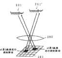
另外反射调制装置能够采用具有排列了多个CCR的角隅调制阵列;进行配置以成像于上述角隅调制阵列的透镜;和对上述角隅调制阵列中的一个或多个CCR逐个控制反射光的调制的调制装置的构成。如上述那样由于CCR具有朝光的入射方向反射光的性质,所以成像了照明光的光源的CCR朝向其光源返回反射光。如果存在多个光源,则各自的光源已成像的CCR就对相对应的光源返回反射光。利用此,通过按对应于各自的光源的一个或多个CCR逐个进行反射光的调制,就可进行并列传输。In addition, the reflection modulation device can adopt a corner modulation array with a plurality of CCRs arranged therein; a lens configured to form an image on the above-mentioned corner modulation array; The composition of the modulation device. Since the CCR has the property of reflecting light toward the incident direction of light as described above, the CCR of the light source on which the illumination light is imaged returns the reflected light toward the light source. If there are multiple light sources, the CCRs on which the respective light sources have been imaged return reflected light to the corresponding light source. By utilizing this, the parallel transmission can be performed by individually modulating the reflected light by one or more CCRs corresponding to the respective light sources.
此外在此情况下作为对一个或多个CCR逐个进行反射光的调制的装置,还能够构成为利用光闸,或者通过使CCR的反射面变化来进行调制。In addition, in this case, as means for individually modulating the reflected light of one or more CCRs, it is also possible to configure the modulation by using a shutter or by changing the reflection surface of the CCR.
因为照明有时会被熄灭,故第3发明的目的提供一种在灭灯时也可进行通信,另外谋求红外光通信的有效利用的照明光通信装置,和适合用于这种照明光通信装置的照明元件。Since the lighting is sometimes turned off, the object of the third invention is to provide an illuminating light communication device that can communicate even when the light is off, and that can effectively utilize infrared light communication, and an illuminating light communication device suitable for use in such an illuminating light communication device. lighting elements.
在照明光通信装置中,作为用于它的构成,其特征在于,具有:发光并进行照明的照明装置;依照数据来控制上述照明装置的闪烁或者光量并对照明光进行调制的调制装置;通过照明光以外的光通信方式来发送上述数据的通信装置;以及依照上述照明装置的亮灯及灭灯来切换上述调制装置及上述通信装置的动作的切换装置,其中,上述切换装置进行切换以在上述照明装置灭灯时上述通信装置进行动作。作为通信装置能够构成为利用红外光通信来发送数据The illumination light communication device is characterized by comprising: an illumination device that emits light and illuminates; a modulation device that modulates the illumination light by controlling flicker or light quantity of the illumination device according to data; a communication device for transmitting the data by means of optical communication other than illumination light; and a switching device for switching the operations of the modulation device and the communication device according to the lighting and extinguishing of the lighting device, wherein the switching device performs switching to The communication device operates when the lighting device is turned off. Can be configured as a communication device to transmit data using infrared light communication
这样,由照明装置发出通过调制装置进行了调制后的照明光,进行照明光通信,并且组合如红外光通信那样历来所进行的通信装置,在将照明装置亮灯时进行照明光通信,在灭灯时进行利用红外光通信等的通信装置的通信。由此,在照明被熄灭时也能够继续进行通信。In this way, the illuminating light modulated by the modulating means is emitted from the illuminating device to carry out illuminating light communication, and by combining conventional communication devices such as infrared light communication, the illuminating light communication is performed when the illuminating device is turned on, and when the illuminating light is turned off. Communication using a communication device such as infrared light communication is performed while the light is on. Accordingly, communication can be continued even when the lighting is turned off.
此外,作为通信装置能够在进行红外光通信的情况下在设置于照明装置的多个LED元件上内置可选择性地发出红外光的红外光发光元件部而构成。由此,就不需要另行设置在灭灯时所用的通信装置,并且能够在室内利用不会出现影子这样所配置的照明装置来进行红外光通信,能够降低阴影的影响进行稳定的红外光通信。In addition, as a communication device, when infrared light communication is performed, an infrared light emitting element unit capable of selectively emitting infrared light can be built into a plurality of LED elements provided in a lighting device. Therefore, it is not necessary to separately install a communication device for turning off the lights, and infrared light communication can be performed indoors using a lighting device arranged so that no shadows appear, and stable infrared light communication can be performed while reducing the influence of shadows.
另外,在照明光通信装置中,其特征在于,具有:发光并进行照明的照明装置;依照数据来控制上述照明装置的闪烁或者光量并对照明光进行调制的调制装置,其中,上述调制装置依照亮灯及灭灯的切换指示在亮灯时为了进行照明对上述照明装置一边供给充分的电力一边进行与上述数据相应的调制控制,在灭灯时进行与上述数据相应的调制控制并使上述照明装置进行仅通信所必需的闪烁。In addition, the illuminating light communication device is characterized by comprising: an illuminating device that emits light for illuminating; and a modulating device that modulates the illuminating light by controlling flickering or light quantity of the illuminating device according to data, wherein the modulating device conforms to The switch instruction of turning on and turning off the light is to perform modulation control according to the above-mentioned data while supplying sufficient power to the above-mentioned lighting device for lighting when the light is on, and to perform modulation control according to the above-mentioned data when the light is off to make the above-mentioned lighting Blinks necessary for the device to communicate only.
在这种构成中,也能够进行作为照明具有充分的光量的亮灯时的通信,和在光量不需要时通过仅通信所需要的发光来进行灭灯时的通信。从而,用户能够进行照明的亮灯及灭灯,并且在灭灯时也可进行借助于光的通信。Also in such a configuration, it is possible to perform communication when the light is turned on with sufficient light quantity as illumination, and to perform communication when the light is off by only emitting light necessary for communication when the light quantity is unnecessary. Accordingly, the user can turn on and turn off the lighting, and can perform optical communication even when the lighting is turned off.
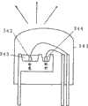
进而,作为发出照明光的照明元件,其特征在于,包括:发出用于照明的白色光的照明发光元件部;以及发出用于红外线通信的红外光的红外光发光元件部。能够构成为通过上述照明发光元件部与上述红外光发光元件部区别进行调制驱动可进行利用了照明光的通信,如上述那样能够进行作为照明在亮灯时借助于照明发光元件部的照明光通信,另外在照明的灭灯时进行借助于红外光发光元件部的红外光通信。由此,在以往的照明光通信中无法进行通信的灭灯时也可进行通信。另外,不需要为了红外光通信而另行设置通信装置,并且能够进行降低了阴影的影响的稳定的红外光通信,能够提高红外光通信的可能性。Furthermore, the lighting element emitting illumination light is characterized by comprising: an illumination light emitting element section emitting white light for illumination; and an infrared light emitting element section emitting infrared light for infrared communication. It can be configured so that communication using illumination light can be performed by separately performing modulation driving of the illumination light-emitting element part and the above-mentioned infrared light-emitting element part, and as described above, it is possible to perform illumination light communication by means of the illumination light-emitting element part when the illumination is turned on. , In addition, when the lighting is turned off, the infrared light communication by the infrared light emitting element part is performed. As a result, communication can be performed even when the light is off when communication cannot be performed in the conventional illumination light communication. In addition, it is not necessary to provide a separate communication device for infrared light communication, stable infrared light communication with reduced influence of shadows can be performed, and the possibility of infrared light communication can be improved.
此外,作为照明元件的构成,能够适用将红、蓝、绿的发光元件部与红外光发光元件部并列进行了配置的构成,或者将由蓝或紫外光的发光元件部和设置于该发光元件部的周围的荧光剂所构成的照明发光元件部与红外光发光元件部进行了并列配置的构成等。In addition, as the structure of the lighting element, it is possible to apply a configuration in which red, blue, and green light-emitting element parts and an infrared light-emitting element part are arranged in parallel, or a light-emitting element part made of blue or ultraviolet light and a light-emitting element part arranged on the light-emitting element part can be applied. A configuration in which the illumination light-emitting element part and the infrared light-emitting element part composed of the surrounding fluorescent agent are arranged side by side.
第4发明的目的是提供一种利用使用了光纤的照明装置,能够进行高速、高品质的通信的照明光通信方式。An object of the fourth invention is to provide an illumination light communication system capable of high-speed and high-quality communication using an illumination device using an optical fiber.
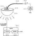
作为用于它的构成,在利用照明光来传送信息的照明光通信方式中,其特征在于,具有:放射照明用的光的光源;通过根据待发送的信息控制光源的亮灭或者光量使调制光进行放射的光源控制装置;对从光源所放射的调制光进行导通的光纤;以及设置在光纤的端部对导通于光纤的调制光进行散射后放射的光散射体,其中,将从光散射体所放射的散射光用于照明并且通过该散射光来发送信息。As its structure, in the illuminating light communication method that transmits information using illuminating light, it is characterized in that: a light source that radiates illuminating light is provided; A light source control device that radiates light; an optical fiber that conducts the modulated light emitted from the light source; The scattered light emitted by the light-scattering body is used for illumination and information is transmitted by the scattered light.
光纤及上述光散射体能够用塑料材料构成。另外,光纤和光散射体能够一体化构成。The optical fiber and the above-mentioned light scatterer can be made of plastic material. In addition, the optical fiber and the light scatterer can be configured integrally.
另外光源能够使用放射紫外线或者蓝色光的光源,此时,能够构成为在光散射体中混入荧光体通过荧光光来进行照明及通信。或者,能够设置发出各自不同颜色的光的多个光源。此时能够构成为光源控制装置对多个光源之中的至少一个进行亮灭或者光量的控制。In addition, a light source that emits ultraviolet light or blue light can be used as the light source, and in this case, it can be configured to perform illumination and communication by mixing fluorescent material into the light scattering body and using fluorescent light. Alternatively, a plurality of light sources emitting lights of different colors can be provided. In this case, the light source control device can be configured to control the on/off or light quantity of at least one of the plurality of light sources.
第5发明的目的是提供一种不需要电缆或光纤的敷设施工,且不会如利用电灯线的通信那样产生频带的限制或电波辐射、噪声的重叠等问题的照明光通信系统,和在这种照明光通信系统中所用的照明装置及照明光源。The object of the fifth invention is to provide an illumination optical communication system that does not require laying construction of cables or optical fibers, and does not cause problems such as frequency band limitation, radio wave radiation, and noise overlap as in communication using lamp wires, and here An illumination device and an illumination light source used in an illumination optical communication system.
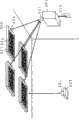
作为用于它的构成,在利用照明光进行通信的照明光通信系统中,其特征在于,具有:发出照明光的多个照明装置,以及对上述照明装置在空间中通过光来发送信息的光通信装置,其中,上述照明装置接受来自上述光通信装置的光以取得信息,并按照上述信息对照明光进行调制。另外本发明,在相同的照明光通信系统中,其特征在于,具有:发出照明光的多个照明装置;以及对一个或多个上述照明装置在空间中通过光来发送信息的光通信装置,其中,一个或多个上述照明装置接受来自上述光通信装置的光以取得信息,对其他照明装置在空间中通过光来进行通信以发送上述信息,在各照明装置中,按照从上述光通信装置或者其他照明装置接收到的上述信息对照明光进行调制并通过照明光来发送信息。As its configuration, the illumination light communication system for communicating using illumination light is characterized by comprising: a plurality of illumination devices emitting illumination light; A communication device, wherein the illumination device receives light from the optical communication device to obtain information, and modulates the illumination light according to the information. In addition, the present invention is characterized in that, in the same illuminating light communication system, there are: a plurality of illuminating devices that emit illuminating light; Wherein, one or more of the above-mentioned lighting devices receive light from the above-mentioned optical communication device to obtain information, and communicate with other lighting devices through light in space to transmit the above-mentioned information. Or the above information received by other lighting devices modulates the lighting light and sends information through the lighting light.
根据这种构成,对于具有调制照明光进行通信的功能的照明装置,将发送的信息从光通信装置或者周围的其他照明装置在空间中通过光被送来。即使是利用相同的光的通信,在利用光纤的情况下,也需要敷设该光纤,但如果在空间中通过光进行通信则不需要。为此,可非常简单地构筑照明光通信系统。另外,如利用电力线的情况那样的频带的限制或电波辐射等之类的问题也不会发生。According to such a configuration, the information to be transmitted is sent from the optical communication device or other lighting devices around to the lighting device having the function of modulating the lighting light for communication through light in space. Even for communication using the same light, it is necessary to lay the optical fiber in the case of using an optical fiber, but it is not necessary to perform communication by light in space. Therefore, an illuminating light communication system can be constructed very simply. In addition, problems such as frequency band limitation and radio wave radiation do not occur as in the case of using electric power lines.
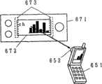
此外,光通信装置能够构成为在光通信装置或其他照明装置之间进行双向通信。进而,通过设置从接受照明光以接收信息的终端装置接受调制光的受光装置,还能够进行与终端装置之间的双向通信。另外照明装置,能够将LED等的半导体发光元件作为照明光源来利用。作为照明装置例如既可以是室内的照明灯,也可以是路灯等。In addition, the optical communication device can be configured to perform two-way communication between the optical communication device or other lighting devices. Furthermore, by providing a light receiving device that receives modulated light from a terminal device that receives illumination light to receive information, bidirectional communication with the terminal device can also be performed. In addition, the illuminating device can utilize a semiconductor light emitting element such as an LED as an illuminating light source. The illuminating device may be, for example, an indoor illuminating lamp or a street lamp or the like.
另外,一种在如上述那样的照明光通信系统中所用的照明装置,其特征在于,具有:发出照明光的一个或多个照明发光装置;用于在与设置于其他装置的发光装置之间的空间通过光来进行通信的光收发装置;以及基于由上述光收发装置所接收到的信息来控制上述照明发光装置,并进行控制以根据上述信息对来自上述照明发光装置的照明光进行调制使上述信息发送的控制装置。In addition, an illuminating device used in the above-mentioned illuminating light communication system is characterized in that it has: one or more illuminating light emitting devices emitting illuminating light; an optical transceiver device for communicating through light in a space; and based on the information received by the optical transceiver device, the above-mentioned illumination light-emitting device is controlled, and the illumination light from the above-mentioned illumination light-emitting device is modulated according to the above-mentioned information. Control means for sending the above information.
根据这种构成,由于如上述那样不需要电缆或光纤等的敷设,所以通过例如仅仅将原有的照明装置更换成本发明的照明装置这样的简单施工,就可构筑照明光通信系统。According to this structure, since the laying of cables, optical fibers, etc. is not required as described above, an illuminating light communication system can be constructed by simple construction such as merely replacing an existing illuminating device with the illuminating device of the present invention.
此外,能够构成为将光收发装置配置在通信方向不同的多个位置,将由某光收发装置所接收到的信息从其他光收发装置对其他装置在空间中通过光来进行发送。据此,就可对照明装置的配置赋予自由度,并且不管照明装置的配置如何都可进行信息的传输。另外,能够构成为光收发装置可与其他装置之间进行双向通信。进而,通过设置从接受照明光以接收信息的终端装置接受调制光的受光装置,还能够进行与终端装置之间的双向通信。另外照明发光装置能够将LED等的半导体发光元件作为照明光源来利用。作为照明装置例如既可以是室内的照明灯,也可以是路灯等。In addition, the optical transceivers can be arranged at a plurality of positions with different communication directions, and information received by a certain optical transceiver can be optically transmitted from other optical transceivers to other devices in space. Accordingly, a degree of freedom can be given to the arrangement of the lighting device, and information can be transmitted regardless of the arrangement of the lighting device. In addition, it is possible to configure the optical transceiver device to be capable of bidirectional communication with other devices. Furthermore, by providing a light receiving device that receives modulated light from a terminal device that receives illumination light to receive information, bidirectional communication with the terminal device can also be performed. In addition, the lighting light-emitting device can use a semiconductor light-emitting element such as an LED as a light source for lighting. The illuminating device may be, for example, an indoor illuminating lamp or a street lamp or the like.
进而,在安装于照明装置所用的照明光源中,其特征在于,具有:出照明光的一个或多个照明发光元件;用于在与设置于其他装置的发光装置之间的空间通过光来进行通信的光收发装置;以及基于由上述光收发装置所接收到的信息来控制上述照明发光元件,并进行控制以根据上述信息对来自上述照明发光元件的照明光进行调制使上述信息发送的控制装置。Furthermore, in the illumination light source installed in the illumination device, it is characterized in that it has: one or more illumination light-emitting elements that emit illumination light; An optical transceiver for communication; and a control device for controlling the above-mentioned illumination light-emitting element based on the information received by the above-mentioned optical transceiver, and controlling to modulate the illumination light from the above-mentioned illumination light-emitting element according to the above-mentioned information to transmit the above-mentioned information .
通过这样在照明光源上设置光收发装置或控制装置,就能够原封不动地利用原有的照明装置,仅通过例如将荧光灯或电灯泡与本发明的照明光源进行更换这样的简单的施工就可构筑照明光通信系统。By arranging the light transmitting and receiving device or the control device on the lighting source in this way, the existing lighting device can be used as it is, and it can be constructed by simple construction such as replacing a fluorescent lamp or an electric bulb with the lighting source of the present invention. Illumination light communication system.
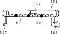
能够构成为在通信方向不同的多个位置上配置光收发装置,将由某光收发装置所接收到的信息从其他光收发装置对其他装置在空间中通过光来进行发送。另外,通过可变更光收发装置的光的收发方向地进行构成,就在被安装于怎样的配置的照明装置的情况下都可进行对应。进而,例如像利用荧光灯的照明装置那样,为了对应配列多个照明光源的情况,作为光收发装置设置用于在与邻接的其他照明光源之间的空间通过光进行通信的装置,和在与安装于其他照明装置的其他照明光源之间的空间通过光进行通信的装置为好。The optical transceivers can be arranged at a plurality of positions with different communication directions, and information received by a certain optical transceiver can be optically transmitted from other optical transceivers to other devices in space. In addition, by configuring the transmission and reception direction of the light of the optical transmission and reception device to be changeable, it is possible to cope with any lighting device installed in any arrangement. Furthermore, for example, like a lighting device using a fluorescent lamp, in order to cope with the situation of arranging a plurality of lighting light sources, a device for communicating by light in the space between other adjacent lighting light sources is provided as an optical transceiver device, and when installed A device that communicates with the space between other lighting sources of other lighting devices through light is preferred.
在此照明光源中,也能够构成为光收发装置可与其他装置之间进行双向通信。进而,通过设置从接受照明光以接收信息的终端装置接受调制光的受光装置,还能够进行与终端装置之间的双向通信。作为照明发光元件,使用LED等的半导体发光元件为好。此外,该照明光源除了室内照明用光源以外,还可以是路灯等室外用光源。In this illumination light source, it is also possible to configure the light transmitting and receiving device to be capable of bidirectional communication with other devices. Furthermore, by providing a light receiving device that receives modulated light from a terminal device that receives illumination light to receive information, bidirectional communication with the terminal device can also be performed. As the lighting light emitting element, it is preferable to use a semiconductor light emitting element such as LED. In addition, the illumination light source may be an outdoor light source such as a street lamp in addition to the light source for indoor illumination.
第6发明,作为第1应用例,其目的是将用于对于人们使光直接可见的显示装置中所用的LED等的半导体发光元件,利用于装置间的通信。The sixth invention, as the first application example, aims to utilize semiconductor light-emitting elements such as LEDs used in display devices for making light directly visible to human beings for communication between devices.
作为用于它的构成,在具有显示用的半导体发光元件的电气设备中,其特征在于,具有:按照信息来控制上述半导体发光元件的亮灭或者发光量的控制装置,并利用显示用的上述半导体发光元件来发送信息。例如,用于显示装置的状态的LED光源或、显示装置的照明用的LED光源等历来根据各自的显示目的来进行设置,通过将该半导体发光元件利用于设备间的通信,就可进行信息的传输而不用设置新的通信装置。另外,即使在具有用于装饰的LED光源的装置中,也能够使诸如该装饰的本来的功能持有信息的传输之类的新功能。另外,在外观上部件也不会增加,且不会损害与以往同样的设计。As a structure for it, in an electrical device having a semiconductor light emitting element for display, it is characterized in that it has a control device for controlling the on-off or light emission of the semiconductor light emitting element according to information, and the above-mentioned light emitting element for display is used. Semiconductor light-emitting elements to transmit information. For example, an LED light source used to display the state of a device or an LED light source for illuminating a display device has been installed according to the respective display purposes. By using this semiconductor light emitting element for communication between devices, information can be exchanged. transfer without setting up a new communication device. In addition, even in a device having an LED light source for decoration, a new function such as transmission of information can be given to the original function of the decoration. In addition, the number of parts does not increase in appearance, and the same design as the conventional one is not damaged.
利用了显示用的半导体发光元件的信息传输,可从本机向其他设备进行信息发送,作为用于接收信息的构成,能够原封不动地利用例如在电视接收机或盒式录像磁带等中广泛得以利用的使用了红外线的接收装置。或者,还能够构成为设置接受来自外部的光的受光装置,从其他装置接收通过对光进行调制所送来的信息,发送接收均能够利用光来进行通信。Information transmission using semiconductor light-emitting elements for display can transmit information from this machine to other equipment. As a structure for receiving information, it can be used intact, such as widely used in television receivers or video cassettes. A receiving device that uses infrared rays is utilized. Alternatively, a light receiving device for receiving light from the outside may be provided, and information transmitted by modulating light may be received from another device, and both transmission and reception may be performed using light for communication.
另外,在具有利用上述的红外线的接收装置的用于对电气设备进行指示的控制器中,其特征在于,具有:接受根据来自电气设备的发送信息经过调制而发出的光以接收发送信息的受光装置;以及用于对电气设备发送指示信息的红外光通信装置。根据这种构成,就能够如上述那样通过用设置于电气设备的显示用的半导体发光元件所发出的光来接收信息,另外通过红外线对电气设备发送信息,并进行对于电气设备的指示。In addition, in the controller for instructing electrical equipment having the above-mentioned receiving device using infrared rays, it is characterized by including a light receiving unit for receiving light modulated according to transmission information from the electrical equipment to receive the transmission information. device; and an infrared light communication device for sending instruction information to electrical equipment. According to this structure, as described above, it is possible to receive information by light emitted by the semiconductor light-emitting element for display provided in the electric device, and to transmit information to the electric device by infrared rays, and to perform instructions to the electric device.
进而,在具有上述的受光装置的用于对电气设备进行指示的控制器中,其特征在于,具有:半导体发光元件;以及按照对上述电气设备发送的指示信息来控制上述半导体发光元件的亮灭或者光量的调制装置。特别是,若设置用于对从半导体发光元件发射的光进行聚光的光学系统,则用于传输信息的光就作为聚光光到达电气设备。如同遮住手电筒那样,能够对欲发送信息的电气设备朝向聚光光,就能可靠地、而且有选择性地、对电气设备通过光来发送信息。Furthermore, in the controller for instructing electric equipment having the above-mentioned light-receiving device, it is characterized by comprising: a semiconductor light-emitting element; Or modulating means of light quantity. In particular, if an optical system for condensing light emitted from the semiconductor light emitting element is provided, the light for transmitting information reaches the electric device as condensed light. Like covering a flashlight, it is possible to reliably and selectively send information to an electrical device through light by directing the focused light toward the electrical device to be transmitted.
此外,在此情况下,通过设置接受自上述电气设备发出并根据发送信息经过调制后的光以接收上述发送信息的受光装置,发送接收均可进行借助于光的通信。Also, in this case, by providing a light receiving device that receives light emitted from the electric device and modulated according to the transmission information to receive the transmission information, communication by light can be performed both for transmission and reception.
另外,能够在设置了受光装置的控制器的构成中,设置用于对受光装置进行聚光的光学系统。根据这种构成,即使在外部的发光源存在多个的情况下,也能够通过光学系统来选择发光源,并能够有选择性地接收发送信息。In addition, an optical system for collecting light from the light receiving device can be provided in the configuration of the controller provided with the light receiving device. According to this configuration, even when there are a plurality of external light emitting sources, the light emitting source can be selected by the optical system, and transmission information can be selectively received.
第7发明,作为第2应用例,其目的是提供一种具有电力效率良好、长寿命的光源的应急灯,并且提供一种将这种应急灯作为异常时的数据发送源进行利用的应急灯无线数据传输系统和在该系统中所利用的应急灯。The object of the seventh invention, as a second application example, is to provide an emergency light having a light source with good power efficiency and a long life, and to provide an emergency light that utilizes such an emergency light as a data transmission source at the time of an abnormality A wireless data transmission system and emergency lights utilized in the system.
作为用于它的构成,在搭载蓄电池,在异常时没有外部电源而使光源亮灯的应急灯中,其特征在于:作为光源使用了LED。由于作为LED的特征即较高的电力效率,就能够抑制蓄电池的消耗、实现因蓄电池的小型化带来的装置的小型化或者发光时间的长期化。另外,由于是长寿命,所以能够将光源的更换等的维护间隔变长,并能够削减维修费用。进而,LED在耐撞击性上也出色,能够提供可在剧烈灾害时不会破损地进行利用的应急灯。As a structure used for it, the emergency light which mounts a battery and turns on a light source without an external power supply at the time of an abnormality is characterized by using LED as a light source. Due to the high power efficiency which is a characteristic of LEDs, it is possible to suppress the consumption of the storage battery and realize the miniaturization of the device due to the miniaturization of the storage battery or the prolongation of the light emitting time. In addition, since it has a long life, maintenance intervals such as replacement of light sources can be lengthened, and maintenance costs can be reduced. Furthermore, LED is also excellent in impact resistance, and can provide the emergency light which can be used without being damaged at the time of a severe disaster.
进而,能够构成为在这种应急灯上设置存储着在异常时进行传输的数据的存储装置;以及基于存储装置所存储的数据来控制向LED供给的电力并控制LED的发光量或者亮灭的光调制装置,通过光来传输数据。如上述那样由于LED其应答特性较好,所以可进行基于这样的数据的调制,能够将用于进行显示的光原封不动地用于数据传输。根据这种构成,就能够将在以往仅仅在紧急出口或紧急楼梯等显示的应急灯作为异常时的信息源进行活用。此时,由于原封不动地利用作为应急灯的光源,所以几乎以光源中的电力消耗程度即可解决而不会如声音输出等那样与光源不同消耗很大功率。从而不需要为了这种数据传输功能而重新搭载大容量的蓄电池,可以显示用所搭载的蓄电池程度进行作为信息源的动作。Furthermore, it can be configured such that such an emergency light is provided with a storage device that stores data transmitted during an abnormality; and based on the data stored in the storage device, it can be configured to control the power supplied to the LED and control the amount of light emitted by the LED or turn on and off. A light modulating device that transmits data by light. As described above, since LEDs have good response characteristics, modulation based on such data can be performed, and light used for display can be used for data transmission as it is. According to such a configuration, it is possible to utilize the emergency lights that have been displayed only at emergency exits, emergency stairs, etc., as an information source at the time of abnormality. At this time, since the light source as the emergency light is used as it is, it can be solved almost at the power consumption level of the light source and does not consume a large power unlike the light source such as sound output. Therefore, there is no need to newly install a large-capacity storage battery for such a data transmission function, and it is possible to display the degree of operation as an information source with the installed storage battery.
进而,还能够构成为设置在异常时以外的时候通过外部电源来驱动的状态下将重叠于外部电源的电压所送来的数据进行分离并解调的解调装置,使通过该解调装置所得到的数据存储在存储装置中。根据这种构成,就能够将在异常时传输的数据在异常时以外的时候通过电源线对各自的应急灯进行配送。由此,就能够容易地进行在异常时发送的数据的设定或更新等。Furthermore, it can also be configured as a demodulation device that separates and demodulates data sent by the voltage superimposed on the external power supply in a state driven by the external power supply at times other than abnormal times, so that the data obtained by the demodulation device The obtained data is stored in the storage device. According to such a configuration, the data transmitted at the time of abnormality can be distributed to the respective emergency lights through the power supply line at times other than the time of abnormality. This makes it possible to easily perform setting or updating of data to be transmitted at the time of abnormality.
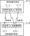
另外本发明,在利用在异常时没有外部电源而使光源亮灯的应急灯将数据传输到终端装置的应急灯无线数据传输系统中,其特征在于,应急灯具有:蓄电池;作为光源的LED;存储着在异常时进行传输的数据的存储装置;以及基于存储装置所存储的数据来控制向LED供给的电力并控制LED的发光量或者亮灭的光调制装置,终端装置具有:接受从应急灯的LED放射的光并变换成电气信号的受光装置;以及对从该受光装置输出的电气信号进行解调以取得数据的解调装置。根据这种构成,就能够在异常时从应急灯通过光将数据传输到终端装置。例如,能够使避难路线或通报目标等各种各样的信息与楼层的地图或文章等一起显示在终端装置,能够在异常时顺利地进行利用者的避难引导。In addition, in the present invention, in the emergency light wireless data transmission system that uses the emergency light that does not have an external power source to turn on the light source to transmit data to the terminal device when there is an abnormality, it is characterized in that the emergency light has: a battery; an LED as a light source; A storage device that stores data transmitted during an abnormality; and a light modulation device that controls the power supplied to the LED and controls the amount of light emitted by the LED or turns on and off based on the data stored in the storage device. The terminal device has: A light-receiving device that converts the light emitted by the LED into an electrical signal; and a demodulator that demodulates the electrical signal output from the light-receiving device to obtain data. According to this configuration, data can be transmitted from the emergency light to the terminal device by light at the time of abnormality. For example, various information such as evacuation routes and notification destinations can be displayed on the terminal device together with floor maps or articles, and evacuation guidance for users can be smoothly performed in the event of an abnormality.
第8发明,作为第3应用例,其目的是提供一种将在路上多数设置的照明装置利用于照明以外的用途,实现顺利的交通,并且对道路的利用者提供种种信息。The object of the eighth invention, as the third application example, is to provide a road user with various types of information to realize smooth traffic by using many lighting devices installed on the road for purposes other than lighting.
作为用于它的构成,在用于通过路上所设置的多个照明装置对路上进行照明的道路照明控制系统及道路照明控制方法中,其特征在于:将照明装置以一个或多个设为照明组,按照明组逐个进行例如亮灭或者光量、或者发光光的颜色等的照明的控制。As its configuration, in the road lighting control system and road lighting control method for illuminating the road with a plurality of lighting devices installed on the road, it is characterized in that one or more lighting devices are used as lighting For each group, control of lighting such as lighting on and off, light quantity, or color of emitted light is performed one by one.
例如能够在路上发生了事故等异常时,利用者进行异常发生的操作或者自动地感知异常来检测异常,按照该异常检测确定进行照明的控制的照明组,就所确定的照明组控制亮灭或光量、颜色等,以报知路上的异常发生。由于路上的照明装置每隔数10米进行配置,所以能够将异常的发生细致地传给道路利用者。另外,由于照明装置设置于较高的位置所以可见性也高,可广泛地通知异常的发生。For example, when an abnormality such as an accident occurs on the road, the user performs an abnormal operation or automatically senses the abnormality to detect the abnormality, determines the lighting group for lighting control according to the abnormality detection, and controls the lighting on or off for the determined lighting group. The amount of light, color, etc., to report abnormal occurrences on the road. Since the lighting devices on the road are arranged at intervals of several tens of meters, the occurrence of abnormalities can be communicated to road users in detail. In addition, since the lighting device is installed at a high position, the visibility is also high, and the occurrence of an abnormality can be widely notified.
另外,在照明装置用半导体发光元件构成的情况下,由于一般而言半导体发光元件具有高速的应答特性,所以通过按照信息使半导体发光元件发出调制光,就能够通过照明光来发送信息。照明光为非常大的电力,通过利用它来发送信息就能够进行可靠的通信。另外,照明装置一般被配置成使路上变得不暗,所以如果从许多照明装置发送相同的信息,即使移动通信也不会中断。反之由于一个照明装置照明的区域不那么宽广,所以通过按一处或数处的照明装置逐个变更将要发送的信息,还可对比较狭窄的区域逐个进行通信。In addition, when the lighting device is composed of semiconductor light emitting elements, since semiconductor light emitting elements generally have high-speed response characteristics, information can be transmitted by illuminating light by causing the semiconductor light emitting elements to emit modulated light according to information. Illumination light is a very large amount of electricity, and by using it to send information, reliable communication can be performed. In addition, lighting devices are generally configured so that the road does not become dark, so if the same information is sent from many lighting devices, communication will not be interrupted even if it is mobile. Conversely, since the area illuminated by one lighting device is not so wide, by changing the information to be transmitted for one or several lighting devices one by one, it is also possible to communicate in a relatively narrow area one by one.
进而,在如上述那样利用从半导体发光元件从照明装置发送信息的情况下,在弯曲的基板上设置多个上述半导体发光元件为好。根据这种构成,就能够使从路上的照明装置离开的地方的明亮度稍微改善,而维持高品质的通信。特别是,通过在照明装置的弯曲的基板的端部使指向性变窄,以进行远距离的照明,就能够进一步发挥该效果。Furthermore, in the case of transmitting information from the lighting device using the secondary semiconductor light emitting element as described above, it is preferable to provide a plurality of the above semiconductor light emitting elements on a curved substrate. According to such a configuration, it is possible to slightly improve the brightness of the place away from the lighting device on the road, and maintain high-quality communication. In particular, this effect can be further exhibited by narrowing the directivity at the end of the curved substrate of the lighting device to perform long-distance lighting.
第9发明,作为第4应用例,其目的是提供一种可高速且高品质地进行移动体通信的移动体光通信系统及移动体光通信方法。As a fourth application example of the ninth invention, it is an object to provide a mobile optical communication system and a mobile optical communication method capable of performing high-speed and high-quality mobile communication.
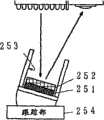
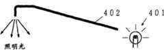
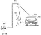
作为用于它的构成,在对移动体发送信息的移动体光通信系统中,其特征在于:对根据信息经过调制后的光信号进行导通并且自表面将光信号泄漏的泄漏光纤沿上述移动体的移动路径进行敷设,上述移动体具有,大致相对着上述泄漏光纤设置并接受从上述泄漏光纤泄漏的光信号的受光装置;以及对由上述受光装置所接受的光信号进行解调以取得信息的解调装置,通过上述泄漏光纤借助于光将信息发送到上述移动体。As its configuration, in the mobile optical communication system that transmits information to the mobile body, it is characterized in that the leaky optical fiber that conducts the optical signal modulated according to the information and leaks the optical signal from the surface moves along the above-mentioned The moving path of the moving body is laid, and the moving body has a light receiving device arranged approximately opposite to the leaky optical fiber and receiving an optical signal leaked from the leaky optical fiber; and demodulating the optical signal received by the light receiving device to obtain information The demodulation device transmits information to the above-mentioned moving body by means of light through the above-mentioned leaky optical fiber.
另外,在对移动体发送信息的移动体光通信方法中,其特征在于:将自表面泄漏光信号的泄漏光纤沿上述移动体的移动路径进行敷设,另外在上述移动体上使接受从上述泄漏光纤泄漏的光信号的受光装置大致相对着上述泄漏光纤进行设置,并且设置对用上述受光装置所接受的光信号进行解调以取得信息的解调装置,使上述泄漏光纤导通根据信息经过调制后的光信号并使光信号从上述泄漏光纤的表面泄漏,通过设置于上述移动体的上述受光装置接受从上述泄漏光纤的表面泄漏的光信号后用上述解调装置进行解调,而取得信息,由此通过上述泄漏光纤借助于光将信息发送到上述移动体。In addition, in the mobile optical communication method for transmitting information to a mobile body, it is characterized in that: a leaky optical fiber that leaks an optical signal from the surface is laid along the moving path of the mobile body, and the mobile body receives light from the leak The light-receiving device for the optical signal leaked from the optical fiber is arranged roughly opposite to the above-mentioned leaky optical fiber, and a demodulation device for demodulating the optical signal received by the above-mentioned light-receiving device to obtain information is provided, so that the above-mentioned leaky optical fiber conduction is modulated according to the information After receiving the light signal leaked from the surface of the above-mentioned leaky optical fiber by the above-mentioned light receiving device installed on the above-mentioned moving body, the optical signal is demodulated by the above-mentioned demodulation device to obtain information , whereby information is transmitted to the above-mentioned moving body by means of light through the above-mentioned leaky optical fiber.
在这样对移动体发送信息的情况下,使光信号从敷设在移动体的路径的泄漏光纤泄漏,通过设置于移动体的受光装置来接受所泄漏的光信号。在敷设有连续的泄漏光纤的区间,由于从泄漏光纤泄漏相同的光信号,所以如果在该区间内即使移动体移动也能够接受相同的光信号。此时,由于是用移动体接受沿移动路径泄漏的光而不是来自固定的点的光,所以能够大致保持泄漏光纤与移动体的距离并且成为近距离的收发光。从而就可进行高品质的通信。另外由于使用光所以难以受到如电波那样的多通路衰落的影响,即使在隧道内等也能够保持通信品质,另外还可实现高速的通信。When transmitting information to a moving object in this way, an optical signal is leaked from a leaky optical fiber laid in a path of the moving object, and the leaked optical signal is received by a light receiving device provided on the moving object. In the section where the continuous leaky optical fiber is laid, since the same optical signal leaks from the leaky optical fiber, the same optical signal can be received even if the moving object moves in this section. At this time, since the light leaked along the moving path is received by the moving body instead of the light from a fixed point, the distance between the leaky fiber and the moving body can be kept substantially and the light can be transmitted and received at a short distance. Thus, high-quality communication can be performed. In addition, since light is used, it is difficult to be affected by multi-path fading such as radio waves, and communication quality can be maintained even in tunnels, etc., and high-speed communication can also be realized.
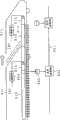
进而,在从移动体发送信息的移动体光通信系统中,其特征在于:上述移动体具有,对信息进行调制的调制装置;将经过调制后的信息作为光信号进行放射的发光装置;以及对从上述发光装置放射的光信号进行导通并且自表面将光信号泄漏的泄漏光纤,另外大致相对着上述移动体的上述泄漏光纤设置,接受从上述泄漏光纤泄漏的光信号并变换成电气信号的受光装置沿上述移动体的移动路径以规定的间隔配置多个,通过设置于上述移动体的上述泄漏光纤借助于光将信息从上述移动体发送。Furthermore, in the mobile optical communication system for transmitting information from the mobile body, the mobile body has modulation means for modulating the information; light emitting means for emitting the modulated information as an optical signal; and A leaky optical fiber that conducts the optical signal radiated from the light-emitting device and leaks the optical signal from the surface, and is installed approximately opposite to the leaky optical fiber of the above-mentioned moving body, and receives the optical signal leaked from the leaky optical fiber and converts it into an electrical signal. A plurality of light receiving devices are arranged at predetermined intervals along a moving path of the moving body, and information is transmitted from the moving body by light through the leaky optical fiber provided on the moving body.
进而,另外在从移动体发送信息的移动体光通信方法中,其特征在于:在上述移动体上设置对信息进行调制的调制装置;将经过调制后的信息作为光信号进行放射的发光装置;以及对从上述发光装置放射的光信号进行导通并且自表面将光信号泄漏的泄漏光纤,将接受从上述移动体的上述泄漏光纤泄漏的光信号并变换成电气信号的受光装置大致相对着上述泄漏光纤、沿上述移动体的移动路径以规定的间隔配置多个,在上述移动体中将信息用上述调制装置进行调制并用上述发光装置作为光信号发射至上述泄漏光纤,通过上述受光装置接受从上述泄漏光纤的表面泄漏的光信号并变换成电气信号,由此进行来自上述移动体的信息的发送。Furthermore, in the mobile optical communication method for transmitting information from a mobile body, it is characterized in that: a modulation device for modulating information is provided on the mobile body; a light emitting device for emitting modulated information as an optical signal; And the leaky optical fiber that conducts the optical signal radiated from the above-mentioned light emitting device and leaks the optical signal from the surface, and the light receiving device that receives the optical signal leaked from the above-mentioned leaky optical fiber of the above-mentioned moving body and converts it into an electrical signal is approximately opposite to the above-mentioned A plurality of leaky optical fibers are arranged at predetermined intervals along the moving path of the moving body. In the moving body, information is modulated by the modulation device and transmitted to the leaky optical fiber by the light emitting device as an optical signal, and received by the light receiving device. The optical signal leaked from the surface of the leaky optical fiber is converted into an electrical signal, whereby information from the moving body is transmitted.
在这样从移动体发送信息的情况下,也是使光信号从设置于移动体的泄漏光纤泄漏,通过沿移动体的移动路径以规定的间隔所配置的受光装置来接受所泄漏的光信号。即使移动体移动、泄漏光纤移动,光信号在相当于泄漏光纤的长的区间泄漏。从而,如果多个配置的受光装置的至少一个接受从移动体的泄漏光纤所泄漏的光信号,就能够接收来自移动体的信息。另外,由于移动体上的泄漏光纤与受光装置的距离大致保持恒定,所以可进行高品质的通信。另外由于使用光所以难以受到如电波那样的多通路衰落的影响,即使在隧道内等也能够保持通信品质,另外还可实现高速的通信。Even when information is transmitted from the moving object in this way, optical signals are leaked from leaky optical fibers provided on the moving object, and the leaked optical signals are received by light receiving devices arranged at predetermined intervals along the moving path of the moving object. Even if the moving body moves and the leaky fiber moves, the optical signal leaks over a long section corresponding to the leaky fiber. Therefore, when at least one of the plurality of arranged light receiving devices receives the light signal leaked from the leaky optical fiber of the moving body, information from the moving body can be received. In addition, since the distance between the leaky optical fiber on the moving object and the light receiving device is kept substantially constant, high-quality communication can be performed. In addition, since light is used, it is difficult to be affected by multi-path fading such as radio waves, and communication quality can be maintained even in tunnels, etc., and high-speed communication can also be realized.
根据这些第9发明,就能够进行向移动体的信息的发送或者来自移动体的信息的发送。在此情况下,移动体侧的泄漏光纤或受光装置能够设置在移动体的地板里,能够将地上侧的泄漏光纤或受光装置设置在轨道内。由于在进行通信之际移动体覆盖轨道,所以能够在黑暗中进行借助于光的通信,所以能够降低太阳光等扰乱光的影响进行高品质且高速的通信。According to these ninth inventions, it is possible to transmit information to or from a mobile body. In this case, the leaky optical fiber or the light receiving device on the moving body side can be installed in the floor of the moving body, and the leaky optical fiber or the light receiving device on the ground side can be installed in the rail. Since the mobile body covers the track during communication, communication by light can be performed in the dark, so that high-quality and high-speed communication can be performed while reducing the influence of disturbing light such as sunlight.
附图说明Description of drawings
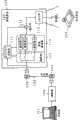
图1是表示本申请第1发明的广播系统的第1实施方式的框图。FIG. 1 is a block diagram showing a first embodiment of a broadcasting system according to the first invention of the present application.
图2(A)是电线上的信号波形的一例的说明图,图2(B)是其部分放大图。FIG. 2(A) is an explanatory diagram of an example of a signal waveform on an electric wire, and FIG. 2(B) is a partially enlarged view thereof.
图3是表示本申请第1发明的广播系统的第2实施方式的框图。Fig. 3 is a block diagram showing a second embodiment of the broadcasting system according to the first invention of the present application.
图4(A)是表示可适用于本申请第1发明的广播系统的电灯泡的一实施方式的概念图,图4(B)是电灯泡的装卸形态的说明图。FIG. 4(A) is a conceptual diagram showing one embodiment of a light bulb applicable to the broadcasting system of the first invention of the present application, and FIG. 4(B) is an explanatory diagram of an attachment and detachment form of the light bulb.
图5是本申请第1发明的第1应用例的说明图。Fig. 5 is an explanatory diagram of a first application example of the first invention of the present application.
图6是本申请第1发明的第2应用例的说明图。Fig. 6 is an explanatory diagram of a second application example of the first invention of the present application.
图7是表示本申请第2发明第1实施方式的概略构成图。Fig. 7 is a schematic configuration diagram showing a first embodiment of the second invention of the present application.
图8是照明侧通信装置1的受光部13中的变形例的说明图。FIG. 8 is an explanatory diagram of a modified example of the
图9是终端侧通信装置2的发光部22中的变形例的说明图。FIG. 9 is an explanatory diagram of a modified example of the light emitting unit 22 of the terminal-side communication device 2 .
图10是表示本申请第2发明的第2实施方式的概略构成图。Fig. 10 is a schematic configuration diagram showing a second embodiment of the second invention of the present application.
图11是利用镜子作为反射调制部24的一构成例的说明图。FIG. 11 is an explanatory diagram of a configuration example using a mirror as the reflection modulation unit 24 .
图12是CCR的概要的说明图。FIG. 12 is an explanatory diagram of an outline of a CCR.
图13是利用了CCR的情况下的调制方法的一例的说明图,图13(A)是使用了光闸的形态的说明图、图13(B)是使用了电介质的形态的说明图、图13(C)是使用了调节器的形态的说明图。FIG. 13 is an explanatory diagram of an example of a modulation method when using a CCR, FIG. 13(A) is an explanatory diagram of a form using a shutter, and FIG. 13(B) is an explanatory diagram of a form using a dielectric. 13(C) is explanatory drawing of the form which used the regulator.
图14是至反射调制部24的入射光和经过调制后的反射光的一例的说明图,图14(A)是表示下行链路的数据传输速度与上行链路的数据传输速度相比高速时的一例的波形图,图14(B)是表示下行链路的数据传输速度与上行链路的数据传输速度程度相当或者在其以下时的一例的波形图。FIG. 14 is an explanatory diagram of an example of incident light to the reflection modulator 24 and modulated reflected light. FIG. 14(A) shows when the data transmission rate of the downlink is higher than that of the uplink. 14(B) is a waveform diagram showing an example when the data transmission rate of the downlink is approximately equal to or lower than the data transmission rate of the uplink.
图15是将CCR作为反射调制部24进行了搭载的照明光通信装置的利用形态的一例的说明图。FIG. 15 is an explanatory diagram of an example of a usage form of an illuminating light communication device in which a CCR is mounted as the reflection modulation unit 24 .
图16是在将CCR作为反射调制部24进行了搭载的照明光通信装置的利用形态的一例中设置了多个照明侧通信装置的情况下的接收信号的合成方法的一例的说明图。FIG. 16 is an explanatory diagram of an example of a method of synthesizing received signals when a plurality of illumination-side communication devices are installed in an example of a usage form of an illumination light communication device equipped with a CCR as the reflection modulation unit 24 .
图17是终端侧通信装置2的反射调制部24中的可并列发送的构成例的说明图。FIG. 17 is an explanatory diagram of a configuration example in which parallel transmission is possible in the reflection modulation unit 24 of the terminal-side communication device 2 .
图18是表示本申请第3发明的照明光通信装置的第1实施方式的框图。Fig. 18 is a block diagram showing a first embodiment of an illuminating light communication device according to the third invention of the present application.
图19是利用开关12~14的接通切断的动作的一例的说明图。FIG. 19 is an explanatory diagram of an example of an operation by turning on and off the
图20是表示适合用于本申请第3发明的照明光通信装置的本申请第3发明的照明元件的一例的模式图。FIG. 20 is a schematic view showing an example of the lighting element of the third invention of the present application which is suitable for the illuminating light communication device of the third invention of the present application.
图21是本申请第3发明的照明元件的一例的对本申请第3发明的照明光通信装置的适用例的说明图。Fig. 21 is an explanatory diagram of an application example of an illuminating element of the third invention of the present application to an illumination light communication device of the third invention of the present application.
图22是表示适合用于本申请第3发明的照明光通信装置的本申请第3发明的照明元件的其他例子的模式图。FIG. 22 is a schematic view showing another example of the lighting element of the third invention of the present application which is suitable for the illuminating light communication device of the third invention of the present application.
图23是本申请第3发明的照明元件的其他例子的对本申请第3发明的照明光通信装置的适用例的说明图。Fig. 23 is an explanatory diagram of an application example of another example of the lighting element of the third invention of the present application to the illuminating light communication device of the third invention of the present application.
图24是表示本申请第3发明的照明光通信装置的第2实施方式的框图。Fig. 24 is a block diagram showing a second embodiment of the illuminating light communication device according to the third invention of the present application.
图25是一般的白色LED的一例的构成图,图25(A)表示设置3色的发光元件的例子,图25(B)表示利用了荧光材料的例子。FIG. 25 is a configuration diagram of an example of a general white LED, FIG. 25(A) shows an example in which three-color light-emitting elements are provided, and FIG. 25(B) shows an example in which a fluorescent material is used.
图26是表示本申请第4发明的第1实施方式的概念图。FIG. 26 is a conceptual diagram showing a first embodiment of the fourth invention of the present application.
图27是表示本申请第4发明的第1实施方式中的第1变形例的概念图。FIG. 27 is a conceptual diagram showing a first modified example in the first embodiment of the fourth invention of the present application.
图28是表示本申请第4发明的第1实施方式中的第2变形例的概念图。FIG. 28 is a conceptual diagram showing a second modified example in the first embodiment of the fourth invention of the present application.
图29是表示本申请第4发明的第2实施方式的概念图。Fig. 29 is a conceptual diagram showing a second embodiment of the fourth invention of the present application.
图30是表示本申请第4发明的第2实施方式的变形例的概略构成图。FIG. 30 is a schematic configuration diagram showing a modified example of the second embodiment of the fourth invention of the present application.
图31是本申请第4发明的应用例的说明图。Fig. 31 is an explanatory diagram of an application example of the fourth invention of the present application.
图32是以往的利用了光纤的照明装置的一例的说明图。FIG. 32 is an explanatory diagram of an example of a conventional lighting device using an optical fiber.
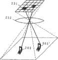
图33是表示本申请第5发明的照明光通信系统的第1实施方式的概念图。Fig. 33 is a conceptual diagram showing a first embodiment of an illumination light communication system according to a fifth invention of the present application.
图34是表示本申请第5发明的照明光通信系统的第2实施方式的概念图。Fig. 34 is a conceptual diagram showing a second embodiment of the illumination light communication system according to the fifth invention of the present application.
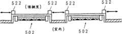
图35是表示本申请第5发明的照明光通信系统的第2实施方式中的照明器具的一例的平面图。35 is a plan view showing an example of a lighting fixture in a second embodiment of the illumination light communication system according to the fifth invention of the present application.
图36是表示本申请第5发明的照明光通信系统的第2实施方式的第1变形例的概念图,图36(A)是截面图,图36(B)是斜视图。36 is a conceptual diagram showing a first modified example of the second embodiment of the illumination light communication system according to the fifth invention of the present application, FIG. 36(A) is a cross-sectional view, and FIG. 36(B) is a perspective view.
图37是表示本申请第5发明的照明光通信系统的第2实施方式的第2变形例的概念图。37 is a conceptual diagram showing a second modified example of the second embodiment of the illumination light communication system according to the fifth invention of the present application.
图38是表示本申请第5发明的照明光通信系统的第2实施方式的第3变形例的概念图。38 is a conceptual diagram showing a third modified example of the second embodiment of the illumination light communication system according to the fifth invention of the present application.
图39是表示本申请第5发明的照明光通信系统的第3实施方式的概念图。Fig. 39 is a conceptual diagram showing a third embodiment of the illumination light communication system according to the fifth invention of the present application.
图40是表示本申请第5发明的照明光通信系统的第3实施方式的其他概念图。Fig. 40 is another conceptual diagram showing a third embodiment of the illumination light communication system according to the fifth invention of the present application.
图41是本申请第5发明的照明光通信系统的第3实施方式中的照明光源的一例的说明图。41 is an explanatory diagram of an example of an illumination light source in a third embodiment of the illumination light communication system according to the fifth invention of the present application.
图42是表示本申请第5发明的照明光通信系统的第4实施方式的概念图。Fig. 42 is a conceptual diagram showing a fourth embodiment of the illumination light communication system according to the fifth invention of the present application.
图43是本申请第5发明的照明光通信系统的第4实施方式中的照明光源的一例的说明图。43 is an explanatory diagram of an example of an illumination light source in a fourth embodiment of an illumination light communication system according to the fifth invention of the present application.
图44是表示本申请第5发明的照明光通信系统的第5实施方式的概念图。Fig. 44 is a conceptual diagram showing a fifth embodiment of the illumination light communication system according to the fifth invention of the present application.
图45是表示本申请第6发明的电气设备的一实施方式的框图。Fig. 45 is a block diagram showing an embodiment of an electric device according to the sixth invention of the present application.
图46是表示本申请第6发明的电气设备的一实施方式中的第1应用例的概略图。Fig. 46 is a schematic diagram showing a first application example in one embodiment of an electric device according to the sixth invention of the present application.
图47是表示本申请第6发明的电气设备的一实施方式中的第1应用例的变形例的概略图。Fig. 47 is a schematic diagram showing a modified example of the first application example in one embodiment of the electric device according to the sixth invention of the present application.
图48是表示本申请第6发明的电气设备的一实施方式中的第2应用例的概略图。Fig. 48 is a schematic diagram showing a second application example in one embodiment of the electric device according to the sixth invention of the present application.
图49是表示本申请第6发明的电气设备的一实施方式中的第2应用例的变形例的概略图。Fig. 49 is a schematic diagram showing a modified example of the second application example in one embodiment of the electric device according to the sixth invention of the present application.
图50是表示本申请第6发明的电气设备的一实施方式中的第3应用例的概略图。Fig. 50 is a schematic diagram showing a third application example in one embodiment of the electric device according to the sixth invention of the present application.
图51是表示本申请第6发明的电气设备的一实施方式中的第4应用例的概略图。Fig. 51 is a schematic diagram showing a fourth application example in one embodiment of an electric device according to the sixth invention of the present application.
图52是表示本申请第6发明的电气设备的一实施方式中的第5应用例的概略图。Fig. 52 is a schematic diagram showing a fifth application example in one embodiment of the electric device according to the sixth invention of the present application.
图53是在电气设备中将LED作为显示用进行利用的形态的一例的说明图,图53(A)表示电视接收机的例子,图53(B)中表示音频设备的例子,图53(C)表示计测器等的仪表的例子。Fig. 53 is an explanatory diagram of an example of a form in which LEDs are used for display in electrical equipment, Fig. 53(A) shows an example of a television receiver, Fig. 53(B) shows an example of audio equipment, and Fig. 53(C ) represents an example of a meter such as a measuring instrument.
图54是在电气设备中将LED作为显示用进行利用的形态的其他例子的说明图,图54(A)表示设置了液晶面板的设备的例,图54(B)表示节点个人计算机的例子,图54(C)表示利用于圣诞树的灯饰的例子。FIG. 54 is an explanatory diagram of another example of a form in which LEDs are used for display in electrical equipment. FIG. 54(A) shows an example of equipment equipped with a liquid crystal panel, and FIG. 54(B) shows an example of a node personal computer. Fig. 54(C) shows an example of illuminations used for Christmas trees.
图55是表示本申请第7发明的应急灯以及应急灯无线数据传输系统的一实施方式的框图。Fig. 55 is a block diagram showing an embodiment of an emergency light and an emergency light wireless data transmission system according to the seventh invention of the present application.
图56是作为光源的LED阵列的一例的说明图,图56(A)表示拆掉应急灯的灯罩的外观,图56(B)表示所用的LED阵列的一例,图56(C)表示设置于灯罩的图画显示的其他例子。Fig. 56 is an explanatory diagram of an example of an LED array as a light source. Fig. 56(A) shows the appearance of the lampshade of the emergency light removed, Fig. 56(B) shows an example of the LED array used, and Fig. 56(C) shows an Drawings of lampshades show other examples.
图57是表示本申请第7发明的应急灯及应急灯无线数据传输系统的其他实施方式的框图。Fig. 57 is a block diagram showing another embodiment of the emergency light and the emergency light wireless data transmission system according to the seventh invention of the present application.
图58是表示本申请第8发明的道路照明控制系统的第1实施方式的框图。Fig. 58 is a block diagram showing the first embodiment of the road lighting control system according to the eighth invention of the present application.
图59是异常发生时的照明灯的照明的形态的一例的说明图。FIG. 59 is an explanatory diagram of an example of a lighting form of a lighting lamp when an abnormality occurs.
图60是表示本申请第8发明的道路照明控制系统的第2实施方式的概略构成图。Fig. 60 is a schematic configuration diagram showing a second embodiment of a road lighting control system according to the eighth invention of the present application.
图61是表示照明灯的发光部分的基板形状的一例的概略截面图。Fig. 61 is a schematic cross-sectional view showing an example of a substrate shape of a light-emitting portion of an illuminating lamp.
图62是表示本申请第9发明的一实施方式的概略构成图。Fig. 62 is a schematic configuration diagram showing an embodiment of the ninth invention of the present application.
图63是向本申请第9发明的一实施方式中的移动体11发送信息时(下行链路)的动作的一例的说明图。FIG. 63 is an explanatory diagram of an example of operations when transmitting information to the mobile body 11 (downlink) in one embodiment of the ninth invention of the present application.
图64是从本申请第9发明的一实施方式中的移动体11发送信息时(上行链路)的动作的一例的说明图。FIG. 64 is an explanatory diagram of an example of operations when information is transmitted (uplink) from the
具体实施方式Detailed ways
<第1发明><the first invention>
首先,就本申请第1发明进行说明。第1发明涉及通过光来配送信息的广播系统、和适合用于这种广播系统的电灯泡。First, the first invention of the present application will be described. The first invention relates to a broadcasting system for distributing information by light, and a light bulb suitable for use in such a broadcasting system.
作为通信系统之一,电力线通信系统得以研究。此电力线通信系统是将敷设于房屋或大楼、供给电力的电力线原封不动用作信号传输介质来传输信息的。电力线是普及率非常高的基本设施,基本上可在用电力线所连结的设备间进行通信。但是,在例如像便携终端等那样未用电力线所连结的设备之间则无法进行通信。本发明提供以下广播系统对未用该电力线所连结的设备,特别是对多数的设备配送信息。As one of the communication systems, the power line communication system is studied. In this power line communication system, the power lines installed in houses or buildings to supply power are used as signal transmission media to transmit information. Power lines are basic facilities with a very high penetration rate, and it is basically possible to communicate between devices connected by power lines. However, communication cannot be performed between devices that are not connected by power lines, such as portable terminals, for example. The present invention provides the following broadcasting system to distribute information to devices not connected with the power line, especially to a large number of devices.
图1是表示本申请第1发明的广播系统的第1实施方式的框图。图中,101是信息源,102是电力线调制器,103是电力线,104、105是万能插口,106是LED照明器具,107是受光终端,111是AC/DC变换部,112是带通滤波器,113是选择部,114是叠加部,115是LED组。信息源101除了计算机以外,还能够由TV或CATV,无线电收音机、有线广播等的调谐器或接收机等、输出各种各样的信息的设备构成。从而,作为进行广播的信息,还可以是映像或音乐、声音、图像、文字数据等各种各样的信息。进行广播的信息还可以为一个或多个,在这里设多个信息被输出。FIG. 1 is a block diagram showing a first embodiment of a broadcasting system according to the first invention of the present application. In the figure, 101 is an information source, 102 is a power line modulator, 103 is a power line, 104 and 105 are universal sockets, 106 is an LED lighting appliance, 107 is a light receiving terminal, 111 is an AC/DC conversion unit, and 112 is a bandpass filter , 113 is a selection part, 114 is a superposition part, 115 is an LED group. The
电力线调制器102对从信息源101输出的一个或多个信息进行调制和多路化,并重叠于电力波形后送出到电力线103。此外,在通常的电力线通信中,为了实现双向通信还具有解调装置的情况较多,但由于在广播系统中是单向的通信所以不需要解调装置。另外,在此例子中作为信息的多路化方法的一例通过频率分割来进行多路化。The
电力线103一般是敷设于室内、室外的电线。该电力线103能够使用原有的电线。另外,为了从电力线103接受电力的供给,在墙面等上设置万能插口104,105等。此万能插口104,105也能够使用原有的插座。在图1所示的例子中,设将电力线调制器102插入万能插口104,另外,将LED照明器具106插入万能插口105来使用。当然,电力线103以及万能插口104,105均重新进行设置也无妨。此外,在此例子中设作为电力供给被用作一般的商用电力的交流电力。The
LED照明器具106是连接到电力线103用于照明附近的照明器具。例如若在室内则设置于顶棚等。除此以外还可以是聚光照明等、种种用途的照明器具。在此例子中,LED照明器具106包含AC/DC变换部111、带通滤波器112、选择部113、叠加部114、LED组115等而构成。The
由于为了使LED组115发光需要通过直流电力来进行驱动,所以AC/DC变换部111是将从电力线103供给的交流电力变换成直流。作为AC/DC变换部111能够使用已有的技术。另外,还结合LED组115的动作电压来进行电压的调整。进而,在带通滤波器112中还进行动作所需要的电力的供给。此外,如上述那样由于在电力线103上重叠着经过调制后的信息的波形,所以希望例如通过平滑化电路等使得信息的波形尽量不出现在直流波形上。Since the
带通滤波器112是为了抽取在电力线103上所重叠的信息的信号而设置的。如上述那样,在该例子中由于各自的信息通过频率分割被多路化,所以可以由仅仅使特定频率通过的带通滤波器112从多个信息之中有选择性地分离一个信息。在图1所示的例子中表示出分别并列设置使通过的频率不同的多个带通滤波器的例子。或者、还能够由可以变更使通过的频带的带通滤波器构成。此外,关于经过分离后的信息的波形,还可以外加偏压、或者实施整形或放大等。The
选择部113选择在设置于带通滤波器112的多个滤波器之中将使用的一个或多个滤波器,由此来选择用光来进行配送的信息。选择除了用手动进行以外,还可以有选择性地解调作为某特定频率所送来的控制信号,并根据该控制信号来进行滤波器的选择这样来构成等、也可以是通过其他方法来进行选择这样的构成。或者,也可以是采用可以变更带通滤波器112使之通过的频率的构成,选择部113对带通滤波器112设定与配送的信息相应的频率这样的构成。虽然在图1中将选择部113设置在带通滤波器112的前级,但也可以设置于其后级。另外,在可以变更带通滤波器112使之通过的频带的构成的情况下也可以是作为选择部113按照特定频率的控制信号对带通滤波器112设定频带这样的构成。进而,在作为该LED照明器具106仅仅配送以固定的频率所送来的信息的情况下则不设置选择部113、作为带通滤波器112具备使固定的频带通过的滤波器即可。The
叠加部114使由带通滤波器112抽取出的信息的信号重叠在用AC/DC变换部111变换成直流的电力波形上。由此就能够根据信息的信号使外加于LED组115的电压变化,并能够控制LED组115的光量或者亮灭。还可以是例如在使LED组115亮灭的情况下根据来自带通滤波器112的信号对来自AC/DC变换部111的电力进行ON/OFF控制这样的构成。The superimposing
LED组115基本上是用于进行照明的LED光源,例如能够用多数白色LED等构成。当然,采用汇集红、蓝、绿的LED的构成也同样如此。该LED组115由从叠加部114给与的电力进行驱动后发光。由于LED应答特性较好,所以能够通过根据信息的信号使光量变化,或者进行亮灭利用光来配送信息。此时,即便使光量高速变化或使其亮灭,由于人们的眼睛不会有知觉所以也能够作为照明原封不动进行利用。The
受光终端107是具有受光装置,接受从LED照明器具106照射的光并抽取信息的信号,进行解调以接收信息的终端。受光终端107只要具有受光装置的话就可以是任意的装置,除了个人计算机或便携终端、便携电话等以外,还可以是设置有受光装置的音频设备、电视机等的显示设备等、各种各样的设备。The
其次,就本申请第1发明的广播系统的第1实施方式中的动作的一例简单地进行说明。作为信息源101,准备进行广播的各种各样的内容。例如除了来自计算机的数据以外,依照用途准备好TV或CATV、无线电收音机、有线广播等、各种各样的信息。Next, an example of operation in the first embodiment of the broadcasting system according to the first invention of the present application will be briefly described. Various contents to be broadcast are prepared as the
从信息源101输出的一个或多个信息在电力线调制器102中经过调制、多路化后被重叠于电力波形、并送出到电力线103。图2是电线上的信号波形的一例的说明图。在该例子中,表示利用商用的交流电源(50Hz/60Hz),使信息的信号波形重叠在电波形上的例子。为了避免对其他设备的影响,重叠信息的信号波形比电力波形小的波形。在图2(B)所示的放大图中,表示以BPSK等方式对信息进行调制后与电力波形进行重叠的例子。此外,电力线103能够利用原有的电线。另外,如果从万能插口取得电力同时分离信息进行使用,则能够进行与一般所利用的电力线通信同样的信息提供。One or more pieces of information output from the
通过电力线103、将电力及信息从万能插口105发送到LED照明器具106。在LED照明器具106中,从万能插口105获得载有信号波形的电力。然后,一方面用AC/DC变换部111将其整流成用于驱动LED组115的直流电力、发送到叠加部114。另一方面用由选择部113所选择的带通滤波器112内的滤波器仅取出规定的频率成分。此时,根据需要外加偏压或者进行波形的整形或放大等为好。Power and information are sent from the
将这样用AC/DC变换部111变换成直流的电力波形和用带通滤波器112抽取出的信息的信号用叠加部114进行合成后外加给LED组115。在LED组115上所印加的电压按照经合成后的信息的信号波形进行变化。由此LED组115的发光量就按照信息的信号波形进行变化,从而能够发送信息。In this way, the power waveform converted to DC by the AC/
从该LED组115发射的光由设置于受光终端107侧的受光元件进行感光。然后,通过抽取所接受的光量的变化并进行解调就能够在受光终端107取得信息。这样,从信息源101提供的信息之中,在LED照明器具106中所选择的信息就与照明光一起被送出,并在受光终端107中进行接收。此时,即使受光终端107的受光部也可以不与LED照明器具106(LED组115)正确地相对,只要在某种程度上能够接受照明光就能够通过良好的通信品质来取得信息的信号。这是根据因LED照明光是为了照明而使用故表观上的发送电力非常大。在通过历来所用的红外线以同样的信号强度发送信号的情况下,对人体(例如眼睛)的影响未加回避,即使在该意义上利用光的信息的传输也是有利的。The light emitted from the
此外,虽然在这里仅仅表示一个LED照明器具106,但是例如在附近配置个LED照明器具106的情况下,通过选择相同的信息进行广播,就能够对于阴影就变得很强,另外对于移动也变得能够对应。反之即使在附近存在选择其他信息进行广播的LED照明器具106,如果在一个LED照明器具106的附近进行接收,由于来自其他LED照明器具106的光衰减所以影响变小。另外,在诸如这样与其他LED照明器具的干扰成为问题的情况下在对来自信息源101的信息进行调制之际,采用擅长于干扰的调制方式,例如OOK-RZ(On-Off Keying,Return-to-Zero)或OFDM(Orthogonal Frequency Division Multiplexing)等进行调制即可。In addition, although only one
另外,在图1所示的例子中设在LED照明器具106内设置AC/DC变换部111或带通滤波器112等进行了说明。但是并不限于此,也可以构成为例如在照明的接通切断用的墙面开关等上设置这些电路,在从墙面开关到LED照明器具106的电力线部分供给重叠了信息的波形的直流。在此情况下,作为选择部113的开关也能够与照明接通切断用的开关一起设置于墙面。当然,关于各部件的配置并不限于这些例子可以是任意的。In addition, in the example shown in FIG. 1, the AC/
图3是表示本申请第1发明的广播系统的第2实施方式的框图。图中,对与图1相同的部分附加相同符号并省略说明。116是带通滤波器,117是判定部,118是选择部。在该例子中,按LED照明器具106或者信息逐个分配固定的识别信息(IP、PN代码等),通过识别信息的比较仅仅选择特定的信息来进行广播。Fig. 3 is a block diagram showing a second embodiment of the broadcasting system according to the first invention of the present application. In the figure, the same reference numerals are assigned to the same parts as those in FIG. 1 , and description thereof will be omitted. 116 is a bandpass filter, 117 is a determination unit, and 118 is a selection unit. In this example, fixed identification information (IP, PN code, etc.) is assigned to each
电力线调制器102,在这里将来自信息源101的多个信息如分组那样进行分割,在开头附加报头通过时间分割多路复用使其重叠于电力波形。在报头中含有识别信息。Here, the
在LED照明器具106中与LED组115及AC/DC变换部111一起包含带通滤波器116,判定部117,选择部118等而构成。带通滤波器116除去电力的交流成分以分离信息的信号成分。在该例子中,关于多个信息全部的信号通过带通滤波器116。The
判定部117从由带通滤波器116分离后的信息的信号中抽取出报头部分,与预先设定的识别信息进行比较,来判定被送来的信息是否应通过光来进行发送。然后,在是应进行发送的信息的情况下对选择部118选择信息部分的信号使其输出到叠加部114。通过选择部118的信号在叠加部114中与用AC/DC变换部111变换成直流的电力波形进行重叠并供给LED组115。以后与上述的第1实施方式同样,LED组115根据信息的信号使光量变、或者控制亮灭、以进行利用光的信息的传输。另外,通过LED组115的发光来进行照明。The judging unit 117 extracts a header part from the information signal separated by the bandpass filter 116, compares it with preset identification information, and judges whether or not the sent information should be transmitted by light. Then, when it is information to be transmitted, the selection unit 118 selects a signal of the information portion and outputs it to the
在该第2实施方式中,如果例如按LED照明器具106逐个分配识别信息,就能够在将信息送出到电力线103的一侧按LED照明器具106逐个控制进行广播的信息。另外,通过可设定识别信息地进行构成,就能够选择从各自的LED照明器具106进行广播的信息。在此情况下,还可以构成为可设定多个识别信息,选择多个信息通过光来送出。In the second embodiment, for example, if the identification information is distributed for each
在此第2实施方式中也与上述第1实施方式同样能够采取各种形态。另外,关于其优点也与上述第1实施同样。In this second embodiment as well, it is possible to take various forms similarly to the above-mentioned first embodiment. In addition, its advantages are also the same as those of the first embodiment described above.
除了这些实施方式以外,还可以构成为对于用照明光进行配送的信息不进行选择,而是将通过电力线103所送来的信息全部利用光来进行配送,在进行接收的终端侧对信息进行选择。In addition to these embodiments, it is also possible to configure that information delivered by illuminating light is not selected, but all information sent through the
图4是表示可适用于本申请第1发明的广播系统的电灯泡的一实施方式的概念图。图中,121是电灯泡,122是灯头,123是灯座。图4所示的例子,能够作为上述广播系统的各实施方式中的LED照明器具106的一部分进行适用。作为照明器具历来一般的用法是安装白热电灯泡进行利用。在顶棚等预先设置灯座123,如图4(B)所示在灯座123上拧进电灯泡121的灯头122以实现电气连接。在此例子中关于直到电力线103或灯座123的配线部分原封不动利用原有的设备,如图4(A)所示,在电灯泡121内容纳在上述第1或者第2实施方式所示的LED照明器具106内的构成。例如能够收容于电灯泡121的灯头122的部分。另外,与以往的白热电灯泡那样的使用灯丝的点光源不同,由于呈面状地配置多数LED,所以可在其里面容纳电路部分。FIG. 4 is a conceptual diagram showing an embodiment of a light bulb applicable to the broadcasting system of the first invention of the present application. Among the figure, 121 is an electric bulb, 122 is a lamp holder, and 123 is a lamp holder. The example shown in FIG. 4 can be applied as a part of the
通过使用这种电灯泡121,就能够仅仅将一般的白热电灯泡更换成本申请第1发明的电灯泡121,将电灯泡121作为借助于光的信息的发送源来使用。By using such a
当然,自以往所用的各种电灯泡的形状除了如图4所示的形状以外,还使用各种形状的灯泡。关于本申请第1发明的电灯泡121的形状也并不限于图4所示那样的形状,能够以任意的形状进行构成。例如还可以如荧光灯那样构成呈直线状地排列了LED的形状的电灯泡121。As a matter of course, bulbs of various shapes other than those shown in FIG. 4 have been used in the past. The shape of the
其次,就本申请第1发明的广播系统的应用例进行若干说明。图5是本申请第1发明的第1应用例的说明图。图中,131是LED照明器具,132是作品,133是受光终端。图5所示的例子,表示将本申请第1发明的广播系统适用于美术馆或博物馆等的一例。在美术馆或博物馆等中对作品或展示物(以下,称为作品132)逐个实施诸如聚光灯那样的照明,另外还附着作品132的说明。作为照明该作品132的照明器具,使用本申请第1发明的LED照明器具131。另一方面,在向LED照明器具131供给电力的电力线103上重叠作品132的说明信息进行送出。此时重叠在电力线103的说明信息对多数作品132事先进行重叠。然后,在对各作品132逐个设置的LED照明器具131中,有选择性地抽取出关于各自作品的说明信息,如上述那样通过控制照明光的光量或者亮灭利用光将说明信息送出。Next, some application examples of the broadcasting system of the first invention of the present application will be described. Fig. 5 is an explanatory diagram of a first application example of the first invention of the present application. In the figure, 131 is an LED lighting device, 132 is a work, and 133 is a light receiving terminal. The example shown in FIG. 5 shows an example in which the broadcasting system of the first invention of the present application is applied to an art gallery, a museum, or the like. In art museums, museums, etc., lighting such as spotlights is given to works or exhibits (hereinafter referred to as works 132 ) one by one, and descriptions of
鉴赏者如果在作品132之前将受光终端133取出则光被照射到受光终端133,通过取出其光量变化或者亮灭进行解调就能够参照该作品132的说明信息。另外,若鉴赏者移动到下一作品之前,则该作品的说明信息通过照明该作品的光得以传输,如果参照受光终端133就能够参照该作品的说明信息。When the appreciator takes out the
这样,在使每个各作品132的说明信息重叠于电力波形送出到电力线103,对各作品进行照明的LED照明器具131中,通过选择对应的作品132的说明信息利用光进行送出,就能够与作品132的照明一起将各作品132的说明信息提示给鉴赏者。In this way, in the
各作品每个的说明信息并不限于一个。例如在对各作品逐个提供依据多个语言的说明信息的情况下在LED照明器具131中选择对应于进行照明的作品132的多个说明信息通过光来送出。然后,在受光终端133侧对通过光所送出的多个说明信息分别进行分离和解调,从其中选择依据鉴赏者所指定的语言的说明信息提示给鉴赏者即可。或者还可以构成为将成人用的说明信息与少儿用的说明信息等、对一个作品132将多个说明信息从同一LED照明器具131通过光来送出。此外,说明信息并不限于文字信息,例如既可以是声音信息也可以是图像或动画等。另外,还可以是将它们进行适宜组合的信息。The explanatory information for each of the works is not limited to one. For example, when providing explanatory information in a plurality of languages for each work one by one, the
图6是本申请第1发明的第2应用例的说明图。图中,141是LED照明器具,142、143是座位,144是受光终端。该第2应用例,表示对航空机或电车、公交车等适用本申请第1发明的广播系统的例子。在图6所示的例子中,对各座位逐个设置LED照明器具141,并进行各自的座位的照明。与其同时,将通过电力线103所送来的信息利用光进行送出。另外,在前方的座位142的背面设置着受光终端144,就座于座位143的乘客能够参照受光终端144的画面。从LED照明器具141照射的光由受光终端144接受,利用该光所送出的信息由受光终端144取得。乘客能够通过操作受光终端144选择所希望的信息进行视听。Fig. 6 is an explanatory diagram of a second application example of the first invention of the present application. In the figure, 141 is an LED lighting fixture, 142 and 143 are seats, and 144 is a light receiving terminal. This second application example shows an example of applying the broadcasting system of the first invention of the present application to an aircraft, a train, a bus, and the like. In the example shown in FIG. 6, the
特别是,在包含宇宙飞船等的航空机中,由于担心对仪器等的影响所以必须避免在机内使用电波。但是如果是光,则不会有对仪器等的影响,另外也没有对人体的影响。为此,如图6所示就能够通过无线来进行信息的配送。此外,信息的选择除了用LED照明器具141进行以外还可以在受光终端144一侧进行。In particular, in an aircraft including a spacecraft, it is necessary to avoid the use of radio waves inside the aircraft due to concerns about the influence on instruments and the like. However, if it is light, there will be no influence on instruments, etc., and there will be no influence on the human body. Therefore, as shown in FIG. 6, information can be distributed wirelessly. In addition, selection of information may be performed on the side of the
此外,在航空机或电车、公交车等中作为用于照明的电力大多使用直流。从而,在图1或图3所示的构成中,就不需要设置AC/DC变换部111。例如在利用光将通过电力线103所送来的全部信息进行送出的情况下带通滤波器112或叠加部114等也不需要,只要通过从电力线103供给的重叠了信息的波形的电力原封不动驱动LED组就能够利用光来送出信息。In addition, direct current is often used as electric power for lighting in airplanes, trains, buses, and the like. Therefore, in the configuration shown in FIG. 1 or FIG. 3 , it is not necessary to provide the AC/
以上,在这里就本申请第1发明的广播系统表示了两个应用例。但是并不限于这些应用例,可以适用于通过光来配送信息的一切用途。例如除了在一般的办公室等中还用作对桌面上的个人计算机的配送系统以外,也可以在工厂内用于向各工程的信息传输等。进而,还可以进行家庭内的电视机或无线电收音机广播的配送,还可通过便携式的显示器在任意的房间进行视听。在此情况下,还可构成为将相当于调谐器的选择部设置在LED照明器具内,通过用电视机控制器等对LED照明器具内的选择部进行控制来进行选台。另外,还能够构成为例如在进行运动的运动场或节目会场等,将有关正在进行的运动或节目的各种信息或其他会场的信息等重叠于照明光进行送出,用观众具有的便携终端等进行接受以取得信息。As above, two application examples of the broadcasting system of the first invention of the present application have been shown here. However, it is not limited to these application examples, and it can be applied to all uses in which information is distributed by light. For example, in addition to being used as a delivery system to personal computers on desktops in general offices, etc., it can also be used in factories for information transmission to various processes. Furthermore, it is also possible to distribute television or radio broadcasts in the home, and to view and listen to them in any room through a portable display. In this case, it is also possible to configure a selection unit corresponding to a tuner in the LED lighting fixture, and to perform channel selection by controlling the selection unit in the LED lighting fixture with a TV controller or the like. In addition, it can also be configured such that, for example, in a sports field or a program venue where sports are played, various information about ongoing sports or programs or information of other venues are superimposed on the illumination light and sent, and the audience can carry out the monitoring with a portable terminal or the like. Accept for information.
这样,根据本申请第1发明,就能够原封不动地利用用于照明的设备,通过光来配送多数信息。此时,不需要如以往那样另行设置发送装置,也不需要重新敷设通信电缆等。从而,就可以低成本进行广播系统的构筑。另外,也没有如红外线那样眼睛安全等对人体的影响,另外也不会如电波那样针对航空机等的应用受到限制,而能够构筑安全的广播系统。In this way, according to the first invention of the present application, it is possible to use the lighting equipment as it is, and distribute a lot of information by light. In this case, there is no need to separately install a transmission device as in the past, and it is not necessary to re-lay communication cables or the like. Therefore, it is possible to construct a broadcasting system at low cost. In addition, there is no influence on the human body such as eye safety like infrared rays, and there is no restriction on application to aircrafts like radio waves, and a safe broadcasting system can be constructed.
<第2发明><Second Invention>
其次,就本申请第2发明进行说明。第2发明是用于通过光来实现双向通信,至少是在其单向(下行链路)上利用照明光。Next, the second invention of the present application will be described. The second invention is for realizing two-way communication by light, and utilizes illuminating light in at least one direction (downlink).
如在上述第1发明中曾说明过那样,利用照明光的通信,在从照明装置至移动终端的信号传输(以下,称之为下行链路)中,由于能够将庞大的电力利用于通信,所以具有优良的特性。但是,以往的照明光通信仅仅是下行链路的单向,关于从移动终端至照明装置的信号传输(以下,称之为上行链路)则尚未得以研讨。在进行除广播外的一般的通信的情况下,需要在通信设备间进行以用于进行ACK或NACK等交接的控制信号的交换为首的种种数据交换。为此、上行链路非常重要。As described in the above-mentioned first invention, in the communication using illumination light, in the signal transmission (hereinafter referred to as downlink) from the illumination device to the mobile terminal, since a huge amount of power can be used for communication, Therefore, it has excellent characteristics. However, conventional illumination light communication is only a one-way downlink, and signal transmission from a mobile terminal to a lighting device (hereinafter referred to as uplink) has not yet been considered. When performing general communication other than broadcasting, it is necessary to perform various data exchanges between communication devices, including the exchange of control signals for handover such as ACK or NACK. For this, the uplink is very important.
图7是表示本申请第2发明的第1实施方式的概略构成图。图中,201是照明侧通信装置、202是终端侧通信装置、211是调制部、212是照明用光源、213是受光部、214是滤波器、221是受光部、222是发光部、223是处理部。照明侧通信装置201作为照明器具被用于周围的照明,具有发光并进行照明的照明用光源212。虽然在这里设光源为LED,但当然并不限于此,也可以利用LD或其他应答速度较快的发光元件。FIG. 7 is a schematic configuration diagram showing a first embodiment of the second invention of the present application. In the figure, 201 is an illumination side communication device, 202 is a terminal side communication device, 211 is a modulation unit, 212 is a light source for illumination, 213 is a light receiving unit, 214 is a filter, 221 is a light receiving unit, 222 is a light emitting unit, 223 is a processing department. The lighting-
进而在照明侧通信装置201中作为用于进行照明光通信的构成具有调制部211以及受光部213。调制部211是为了实现下行链路而设置的,基于待发送的数据来控制用于驱动照明用光源212的电力。由此,对照明用光源212的光量或者亮灭进行控制,并使基于数据经过调制后的光进行发射。通过在后述的终端侧通信装置202中接受此经过调制后的照明光,就能够进行从照明侧通信装置201至终端侧通信装置202的数据传输(下行链路)。Furthermore, the illumination
调制方式能够利用OOK(ON-OFF Keying)或BPSK等、任意的调制方式。另外,对光量或者亮灭进行控制的LED既可以是为了进行照明所配置的照明用光源212的全部,或者也可以仅仅利用一部分。此外,如上述那样由于LED具有高速的应答特性,所以光量的变化或亮灭不会被人们的眼睛感知,而感觉到是连续进行发光。从而即使进行数据传输,照明用光源212也另外担负照明的任务。As the modulation method, any modulation method such as OOK (ON-OFF Keying) or BPSK can be used. In addition, the LEDs for controlling the light quantity or turning on and off may be all of the
受光部213是为了接受从终端侧通信装置202发出的调制光(红外线或者可见光、紫外光等)而设置的,例如包含光电二极管等受光元件而构成。另外,为了有选择性地接受从终端侧通信装置202发出的调制光,而在此例子中设置有滤波器214。例如在接受红外线的情况下设置使红外线透过的滤波器214即可。当然也可以不设置滤波器214来构成。将接受到的光变换成电气信号,从终端侧通信装置202对数据进行解调后输出。The
此外,通过照明光进行发送的数据也可以是从外部接收到的数据或者在照明侧通信装置201内保持或者生成的数据。另外,关于由受光部213接收到的数据,除了输出到外部以外也可以是在照明侧通信装置201内进行处理的构成。In addition, the data transmitted by the illumination light may be data received from the outside or data held or generated in the illumination-
终端侧通信装置202既可以是任意的终端装置,也可以作为用于进行照明光通信的构成而包含受光部221、发光部222、以及进行终端装置中的各种处理的处理部223等。受光部221接受从照明侧通信装置201发射的经过调制后的发光光,进行解调后传给处理部223。由此就能够接收从照明侧通信装置201借助于照明光所送来的数据,下行链路就成为可能。The terminal
发光部222包含例如LED或LD等光源以及对光源进行驱动控制的控制电路等,接收来自处理部223的待发送的数据,并基于数据对光源的光量或者亮灭进行控制后发射经过调制后的光。调制方式为任意。另外发光光能够利用红外线或者可见光、紫外光等。该调制光通过上述的照明侧通信装置201的受光部213进行受光由此实现上行链路。The light emitting unit 222 includes a light source such as LED or LD and a control circuit for driving and controlling the light source, etc., receives the data to be sent from the processing unit 223, controls the light quantity or on and off of the light source based on the data, and emits modulated light. Light. The modulation method is arbitrary. In addition, infrared light, visible light, ultraviolet light, or the like can be used for the emitted light. This modulated light is received by the
如以上那样,在照明侧通信装置201中,由照明用光源212对周围进行照明,同时基于数据来调制该照明光,由此通过照明光来发送数据。由终端侧通信装置202的受光部221来接收该照明光,由此就能够接收从照明侧通信装置201发送的数据。这样来进行下行链路。另外,在终端侧通信装置202中,基于数据从发光部222发出调制光以发送数据。通过由照明侧通信装置201的受光部213接受该调制光,从终端侧通信装置202发送的数据就在照明侧通信装置201中得以接收。这样来进行上行链路。这样一来,下行链路、上行链路均能够通过光来进行通信,就能够实现利用光的双向通信。As described above, in the illumination-
例如终端侧通信装置202为可移动的终端装置,例如节点个人计算机或PDA、便携电话等、可携带的终端装置,不需要连接电缆等。特别是在带照相机的PDA或便携电话等中可将该照相机作为受光部221进行利用。另外,在利用电波的通信受到限制的利用环境,例如,医院或列车内、航空机、宇宙飞船、领导人的利用者居住的环境等中也可进行利用,也不需要许可等。当然,可在一般的办公室或店铺、家庭、公共设施等、各种各样的环境下进行利用。另外,并不限于室内,例如还可用于霓虹灯广告牌或广告照明,或者在交通系统中用于车与车之间的通信或路上的设施与车之间的通信等,各种各样的用途下的利用。For example, the terminal-
进而,由于光的波长较短,所以能够进行在电波以上的非常高速的通信。进而,一般而言照明器具被广泛设置,另外在利用终端装置的环境中当然也可进行照明。由于能够利用该照明器具来设置照明侧通信装置201进行通信,所以设置成本也可非常降低。Furthermore, since the wavelength of light is relatively short, very high-speed communication over radio waves is possible. Furthermore, lighting fixtures are generally installed widely, and of course lighting can also be performed in an environment where terminal devices are used. Since the lighting fixture can be used to install and communicate with the lighting
此外,在如办公室等那样配置有多个照明器具的环境下可将各自的照明器具作为照明侧通信装置201,以配置多个照明侧通信装置201。在此情况下,可在多个照明侧通信装置201中接受来自1台终端侧通信装置202的发光光。通过这样在多个照明侧通信装置201中进行受光就能够使通信品质得以改善。另外,即使在例如因人通过等而发生阴影,无法用1台照明侧通信装置201进行受光的情况下也能够通过在其他照明侧通信装置201中进行受光将阴影的问题解决。In addition, in an environment such as an office where a plurality of lighting fixtures are arranged, each lighting fixture can be used as the lighting-
其次,就该第1实施方式中的若干主要变形例进行说明。图8是照明侧通信装置201的受光部213中的变形例的说明图。图中,231是二维传感器,232是透镜。能够构成为使用二维传感器231作为照明侧通信装置201的受光部213,通过透镜232使其在受光面上大致成像。在这种构成中,例如来自终端侧通信装置202的发光光在二维传感器231的受光面进行成像,通过设置于二维传感器231的多数受光单元之中的一部分受光单元来接受来自终端侧通信装置202的发光光。此时,由于其他受光单元接受环境光,所以通过使用它就能够除去背景噪声等,可进行高品质的通信。Next, some main modification examples in the first embodiment will be described. FIG. 8 is an explanatory diagram of a modified example of the
另外,例如在受光区域内存在多个终端侧通信装置202、202’的情况下,如图8所示那样在二维传感器231中来自各自的终端侧通信装置202、202’的发光光成像于不同的位置。为此,就可并列地接收来自各自的终端侧通信装置202、202’的数据。当然,对于存在3台以上的终端侧通信装置的情况也同样如此。In addition, for example, when a plurality of terminal-
进而,在设置多台照明侧通信装置201的环境中,能够通过设置于各自的照明侧通信装置201的二维传感器231来接受来自各自的终端侧通信装置202,202’的发光光。在此情况下,可通过二维传感器231上的受光位置与照明侧通信装置201的设置位置等进行各自的二维传感器231中的受光点的同定而使通信品质得到改善。Furthermore, in an environment where a plurality of lighting-
图9是终端侧通信装置202的发光部222中的变形例的说明图。图中,241是跟踪部,242是LED光源,243是镜面,244是透镜。在图7所示的基本构成中,在使用LED光源242作为终端侧通信装置202的发光部222的光源的情况下,发光光将会发散、在照明侧通信装置201中能够受光的光量就会变少。在图9所示的例子中,表示为了防止这种发光光的发散、收拢光束,而设置镜面243及透镜244的例子。通过设置这种光学系统就能够将LED光源242的发光光效率良好地朝向照明侧通信装置201,可进行良好的通信。当然,在使用指向性尖锐的LD等作为光源的情况下镜面243或透镜244等就不需要。FIG. 9 is an explanatory diagram of a modified example of the light emitting unit 222 of the terminal-
另外,在这样收拢光束或者使用LD作为光源的情况下,若发光光没有正确地照射到照明侧通信装置201的受光部213就会发生通信品质低下,或者无法通信之类的事态。为此在图9所示的例子中,设置着用于将光束朝向照明侧通信装置201的受光部213的跟踪部241。跟踪部241除了设置可用手动变更光束的方向的可动机构的构成以外,还可以采用利用照明光等自动地或者根据来自终端装置本体的控制进行动作的构成,或者利用下行链路从照明侧通信装置201进行控制的构成等种种构成。In addition, when the light beam is narrowed in this way or LD is used as the light source, if the emitted light is not properly irradiated to the
以上,就照明侧通信装置201的受光部213中的变形例与终端侧通信装置202的发光部222中的变形例各一个进行了说明。本申请第2发明并不限于这些例子。例如图8所示的构成也能够适用于终端侧通信装置202的受光部。由此,就能够从多个照明侧通信装置通过照明光并列地发送不同的数据,在终端侧通信装置202中将它们进行分离并接收。In the above, the modified examples of the
另外,从照明侧通信装置201发送的数据以及所接收的数据除了使用专用的数据线进行传输以外还可以利用供给用于照明的电力的电力线,使数据重叠于电力波形来进行传输。当然,无需赘言除了它们以外还可进行种种变形。In addition, the data transmitted and received from the lighting-
图10是表示本申请第2发明的第2实施方式的概略构成图。图中,对与图7相同的部分附加相同的符号并省略重复的说明。224是反射调制部。在上述的第1实施方式中,表示为了上行链路而在终端侧通信装置202上设置发光部222,在终端侧通信装置202中进行发光的例子。相对于此,在该第2实施方式中,表示原封不动使用在下行链路中所用的照明光,在上行链路使用反射光的构成。如上述那样照明光为非常大的电力,通过将其用于上行链路,就能够更为可靠地进行通信。另外,由于不需要在终端侧通信装置202设置发光部222,所以能够较大地抑制终端侧通信装置202的电力消耗,也能够大大有助于省电力化。此外,由于照明侧通信装置201的构成与上述的第1实施方式及其变形例同样,所以在这里省略说明,同时调制部211的图示也省略。另外,关于终端侧通信装置202的受光部221也与上述第1实施方式及其变形例等同样。Fig. 10 is a schematic configuration diagram showing a second embodiment of the second invention of the present application. In the figure, the same reference numerals are assigned to the same parts as those in FIG. 7 , and overlapping descriptions will be omitted. 224 is a reflection modulator. In the first embodiment described above, an example was shown in which the light emitting unit 222 is provided in the terminal
作为用于在上行链路上使用照明光的构成,在终端侧通信装置202中设置有反射调制部224。反射调制部224对照明光进行反射,同时送出根据通过上行链路发送的数据经过调制后的反射光。As a configuration for using illumination light on the uplink, the
图11是作为反射调制部224利用了镜子的一构成例的说明图。图中,251是镜子,252是光闸,253是遮蔽壁,254是跟踪部。作为反射照明光的装置,单纯使用镜子251,设置与图9所示的变形例中的跟踪部241同样的跟踪部254对反射方向进行控制即可。另外,作为调制方法在这里使用光闸252,能够通过对至镜子251的入射光以及自镜子251的反射光进行透过/遮断来进行。作为光闸252例如使用液晶光闸,能够通过基于数据对液晶的取向进行控制来进行反射光的开关控制以进行调制。当然也可以是其他调制方法,例如还能够仅仅基于数据使镜面的反射方向变化来进行调制。即,由于通过使镜面的反射方向改变,入射到照明侧通信装置201的受光部213的光量发生变化,所以如果检测该变化就能够将数据取出。在此情况下,还可以例如将跟踪部254兼用作调制装置。FIG. 11 is an explanatory diagram of a configuration example using a mirror as the
另外在图11所示的例子中,在镜251的周围配置有遮蔽壁253。这是为了防止来自进行通信的照明侧通信装置201以外的光源的光通过镜子251进行反射,进入到用户的眼睛变得晃眼而设置。在照明侧通信装置201的照明用光源212及受光部213接近而得以配置的情况下,仅仅对来自照明用光源212的光进行反射以使其返回受光部213即可,所以其他的光的反射就不需要。为了防止这样的不需要的反射而设置有遮蔽壁253。也能够通过将该遮蔽壁253的内面也设为镜面来使反射光量增加。当然,也可以不设置遮蔽壁253来构成。In addition, in the example shown in FIG. 11 , a shielding
此外,除了将这种图11所示的单元单独使用以外,还能够配置多个来构成。In addition, besides using such a unit shown in FIG. 11 alone, it is also possible to arrange a plurality of units and configure it.
在反射调制部224中作为反射照明光的装置,能够利用CCR(Corner Cube Reflector)。图12是CCR概要的说明图。CCR具有使3面反射面向内相互垂直的形状。例如图12所示那样,通过将形成立方体或者直方体的1顶点的相互垂直的3个内面设为反射面而得到。A CCR (Corner Cube Reflector) can be used as means for reflecting the illumination light in the
作为该CCR的特征,具有朝光的入射方向发射光的特性。从而,如果照明光被入射就朝向该照明光的光源来反射照明光。虽然在本申请第2发明中将照明光用于下行链路,但通过反射在该下行链路中所用的照明光,就可原封不动也利用于上行链路。特别是由于朝向照明光源进行反射,所以只要接近照明侧通信装置201的照明光源设置受光部213就能够接受反射光。另外,由于指向性较好、较强的反射光入射到照明侧通信装置201的受光部213,所以还有难以受到因周边光造成的影响的优点。此外,照明侧通信装置201被设置于任意的位置即可,反之即使终端侧通信装置202存在于任意的位置,反射光也朝向照明侧通信装置201进行反射。As a feature of this CCR, it has a characteristic of emitting light in a light incident direction. Therefore, when the illumination light is incident, the illumination light is reflected toward the light source of the illumination light. In the second invention of the present application, the illuminating light is used for the downlink, but by reflecting the illuminating light used for the downlink, it can also be used for the uplink as it is. In particular, since the light is reflected toward the illumination light source, the reflected light can be received by providing the
图13是利用了CCR的情况下调制方法的一例说明图。图中,261是CCR,262是光闸,263是电介质,264是调节器。如上述那样能够通过CCR将照明光朝向照明侧通信装置201进行反射,表示用于将该反射光根据数据进行了调制的若干方法。在图13(A)中表示将光闸262配置在CCR前面进行调制的例子。作为光闸262能够用例如使用了液晶显示装置的液晶光闸进行构成。液晶光闸根据电压的外加使液晶的取向变化,以切换光的透过和遮断。使用该液晶光闸,例如若控制液晶光闸以使光透过,则如上述那样来自照明侧通信装置201的照明光入射至CCR261,反射光就朝向照明侧通信装置201。反之若控制液晶光闸以使光遮断,则至CCR261的入射光以及反射光均被遮断、照明侧通信装置201的受光部213就变得无法接受反射光。这样就能够通过控制液晶光闸的液晶取向来进行反射光的开关控制。通过按照数据进行该开关控制就能够将经过调制后的反射光送至照明侧通信装置201。当然作为液晶存在各种各样,可适宜使用这些种种液晶。例如还可以对光的透过和反射进行切换。另外,虽然在此例子中使用了液晶光闸作为光闸262,但除此以外只要是能够控制至CCR261的照明光以及反射光的入出光的光闸机构,则怎样构成光闸都能够进行利用。FIG. 13 is an explanatory diagram of an example of a modulation method when CCR is used. In the figure, 261 is a CCR, 262 is a shutter, 263 is a dielectric, and 264 is a regulator. As described above, the illumination light can be reflected toward the illumination-
在图13(B)所示的例子中,通过在构成CCR261的镜面的部分或全部将电介质263接近(λ/3)配置,使内面的全反射的量衰减。能够通过依照数据使电介质的位置变化,来控制CCR261中的反射光量,并能够将由此经过调制后反射光送至照明侧通信装置201。此外,此方式利用了光的相干性,限于利用LD作为照明侧通信装置201的光源的情况等。In the example shown in FIG. 13(B), the amount of total reflection on the inner surface is attenuated by arranging the dielectric 263 close to (λ/3) part or all of the mirror surface constituting the
图13(C)所示的例子,在构成CCR261的镜面的1面安装调节器264,依照数据使镜面变化。例如通过改变镜面的角度、或者使镜面歪斜来使CCR261中的各镜面间的光的反射角度变化,能够破坏反射光返回到入射光的方向这样的关系。可通过按照数据来进行这种控制将经过调制后的反射光送到照明侧通信装置201。作为调节器264除了借助于机械的微型机等的驱动以外,还能够适用利用借助于压电元件等的变形等种种构成。In the example shown in FIG. 13(C), the
图14是至反射调制部224的入射光与经过调制后的反射光的一例的说明图。如上述那样入射到反射调制部224的光是从照明侧通信装置201发射的经过调制后的照明光。从而,按照通过下行链路所发送的数据来控制光量或者亮灭。若原样用CCR261进行反射则在反射光上也重叠了下行链路时的数据保持不变。但是,在与利用下行链路的数据传输速度相比上行链路的数据传输速度较慢的情况下几乎没有问题。例如图14(A)所示在照明光的光量高速变化的情况下如果上行链路的数据传输速度慢则在1数据传输中照明光的光量就要变化好几回。例如在像图13中所说明那样进行调制,用CCR261对入射光进行了反射时,在1数据传输中存在的变亮的部分及变暗的部分的平均光量就在照明侧通信装置201的受光部213进行受光。相对于此在未用CCR261朝向光源进行反射的情况下,就连平均光量都无法在照明侧通信装置201的受光部213进行受光。从而,即使将下行链路的数据剩余不变的照明光用于上行链路也可良好地传输数据。FIG. 14 is an explanatory diagram of an example of incident light to the
反之在利用下行链路的数据传输速度与上行链路的数据传输速度程度相当或者在其以下时,在不存在照明光被完全遮断的时间的情况下能够将照明光的反射光用于上行链路。在图14(B)中表示下行链路与上行链路的数据传输速度相同的情况。在该例子中,作为下行链路的数据调制方式,利用副载波BPSK。在此情况下,由于在1数据的传输时间中、照明光量不会连续为0,所以即使进行用于上行链路的利用开关的调制也能够在照明侧通信装置201的受光部213根据受光量的变化来接收上行链路的数据。Conversely, when the data transmission speed of the downlink is equivalent to or lower than the data transmission speed of the uplink, the reflected light of the illumination light can be used for the uplink without the time when the illumination light is completely blocked. road. FIG. 14(B) shows a case where the data transmission speeds of the downlink and the uplink are the same. In this example, subcarrier BPSK is used as a downlink data modulation scheme. In this case, since the amount of illumination light does not continuously become 0 during the transmission time of 1 data, even if the modulation using the switch for the uplink is performed, the
这样,即使照明光已被调制,通过反射该经过调制后的照明光,并按照上行链路的数据进行调制也能够实现从终端侧通信装置202至照明侧通信装置201的上行链路。照明光为大功率,关于其反射光也具有较大的电力。从而关于上行链路也能够进行高品质的通信。另外,在利用CCR261的构成中,由于反射光返回到入射光的光源,所以完全不需要进行跟踪能够以简易的构成来实现上行链路。进而,还有不需要与下行链路取得同步这样的优点。进而,在利用CCR261的情况下,因乱反射等而使光进入用户的眼睛的情况稀少,还有几乎不会感到晃眼这样的优点。In this way, even if the illumination light is modulated, the uplink from the terminal
图15是将CCR作为反射调制部224进行了搭载的照明光通信装置的利用形态的一例说明图,图16是相同的多个照明侧通信装置中的接收信号的合成方法的一例的说明图。图中,271是受光元件,272是延迟修正部,273是合成部,274是解调部。如上述那样CCR有将反射光朝向光源返回的特性,这种特性在光从多个方向入射的情况下也同样如此。例如像图15所示那样在多个照明侧通信装置201、201’、201”分别发出照明光,入射到终端侧通信装置202时,通过设置于终端侧通信装置202的CCR,来自照明侧通信装置201的照明光朝向照明侧通信装置201进行反射,同样来自照明侧通信装置201’的照明光朝向照明侧通信装置201’进行反射、来自照明侧通信装置201”的照明光朝向照明侧通信装置201”进行反射。由此,来自终端侧通信装置202的上行链路的数据就在多个照明侧通信装置201、201’201”中得以接收。FIG. 15 is an explanatory diagram of an example of a usage form of an illumination light communication device equipped with a CCR as the
在多个照明侧通信装置201、201’、201”中,通过合成各自受光而得到的电气信号就能够可靠地接收数据。在图16中示出此时的电路构成的一例。设置于各自的照明侧通信装置201、201’、201”的受光部213中的受光元件271,将所接受的光变换成电气信号。在将来自此受光元件271的电气信号以对各自的照明侧通信装置201、201’、201”逐个设定的延迟量在延迟修正部272进行修正后,在合成部273进行合成。合成除了例如单纯地进行加法运算以外,还能够取得平均电力或者进行加权后合成。信号强度越强权重就设为越大的权重即可。通过将合成后的电气信号在解调部进行解调就能够取得从终端侧通信装置202送来的数据。In a plurality of lighting-
这样,由于能够对多个照明侧通信装置发送上行链路的数据,所以即使例如因人通过等而使光没有到达一个照明侧通信装置的阴影发生,在其他照明侧通信装置中得以受光因此就能够没有问题地进行通信。此时,跟踪CCR的机构等就不需要,能够以简单的构成来解决作为光通信的障害的阴影。此外,虽然在图15中示出了3台照明侧通信装置,但并不限于此即使在2或者4台以上也同样如此。In this way, since uplink data can be transmitted to a plurality of lighting-side communication devices, even if a shadow occurs where light does not reach one lighting-side communication device due to, for example, people passing by, the other lighting-side communication devices can receive light. Able to communicate without problems. In this case, there is no need for a mechanism to track the CCR, etc., and the shadow that is an obstacle to optical communication can be resolved with a simple configuration. In addition, although three illumination side communication apparatuses are shown in FIG. 15, it is not limited to this, Even if it is two or four or more, it is the same.
虽然在上述的说明中就一个CCR进行了说明,但在配置了多个CCR来构成的情况下也同样如此,例如能够2维状进行配置来构成。在配置了多个CCR的情况下,只要如图13所示那样的用于调制的构成设置在各自的CCR261,全部同样地进行控制就能够使其与CCR为一个的情况同样地进行动作。在例如图13(A)所示的通过光闸262进行调制的构成的情况下还能够构成为在多个CCR上设置共通的光闸262。In the above description, one CCR has been described, but the same is true when a plurality of CCRs are arranged, for example, they can be arranged two-dimensionally. When a plurality of CCRs are arranged, as shown in FIG. 13 , as long as the configuration for modulation is provided in each
在这样配置多个CCR的情况下,还可以对一个或多个的CCR逐个进行调制控制。若利用这样的构成,进行来自终端侧通信装置202的并列的数据发送就成为可能。图17是终端侧通信装置202的反射调制部224中的可并列发送的构成例的说明图。图中,281是CCR阵列,282是透镜。CCR阵列281配置了多个CCR,可按一个或多个的CCR逐个进行调制控制地构成。关于CCR阵列281中的各个CCR,若是进行例如图13(A)所示的利用了光闸262的调制控制,则对一个或多个CCR逐个配置可控制的光闸262即可。另外,若是例如图13(C)所示那样使CCR的镜面变化的构成,则能够对各自的CCR设置同样的构成,其控制对一个或多个CCR逐个来进行。When a plurality of CCRs are arranged in this way, it is also possible to individually perform modulation control on one or more CCRs. With such a configuration, parallel data transmission from the terminal-
在CCR阵列281的入射(出射)侧设置有透镜282,进行调整以使的来自照明侧通信装置201,201’的照明光大致成像于CCR的镜面或者其附近。在这种构成中,例如来自照明侧通信装置201,201’的发光光只入射到CCR阵列281之中各自的一部分CCR。然后,根据CCR的特性来自照明侧通信装置201的照明光所入射的一部分CCR就对照明侧通信装置201返回反射光,来自照明侧通信装置201’的照明光所入射的一部分CCR就对照明侧通信装置201’返回反射光。此时,关于各自的照明光所入射的CCR,只要同样地进行调制控制就能够如上述的图15所说明那样将相同的数据发送至多个照明侧通信装置201,201’。A
这里,关于各自的照明光所入射的CCR,还可以分别基于不同的数据进行调制控制。即,能够进行控制以使得关于来自照明侧通信装置201的照明光被入射,对照明侧通信装置201返回反射光的CCR基于第1数据进行调制控制,关于来自照明侧通信装置201’的照明光被入射、对照明侧通信装置201’返回反射光的CCR则基于与第1数据不同的第2数据进行调制控制。由此,就能够对照明侧通信装置201发送第1数据,对照明侧通信装置201’发送第2数据。这些数据可以并行进行发送,并能够进行并列传输。Here, the CCRs on which the respective illumination lights are incident may be modulated and controlled based on different data. That is, it can be controlled such that the illumination light from the illumination-
此外,关于入射照明光的CCR的确定,除了预先决定以外,还能够构成为与CCR一起配置简单的受光元件,或者在CCR的镜面上组合受光元件,或者作为终端侧通信装置202的受光部221用二维传感器及透镜系统等进行构成,以确定照明侧通信装置的位置。当然,采用其他方法也无妨。In addition, the determination of the CCR of the incident illumination light can be configured by disposing a simple light-receiving element together with the CCR, combining a light-receiving element on the mirror surface of the CCR, or serving as the light-receiving
以上,作为第2实施方式表示了反射照明光用于上行链路的例子。在此第2实施方式中,也与上述第1实施方式同样,照明侧通信装置201能够与一般所利用的照明器具同样地进行设置,关于终端侧通信装置202节点个人计算机或PDA、便携电话等可携带的终端装置为好。另外,关于用途在一般的办公室或店铺、家庭、公共设施、进而利用电波的通信受到限制的利用环境、例如,医院或列车内、航空机、宇宙飞船、领导人的利用者居住的环境等也可以利用,进而并不限于室内,例如还可用于霓虹灯广告牌或广告照明,或者在交通系统中用于车车间通信或路车间通信等、各种各样的用途下的利用。An example in which reflected illumination light is used for an uplink has been described as the second embodiment. Also in this second embodiment, similarly to the above-mentioned first embodiment, the lighting-
另外,在此第2实施方式中也可进行与上述第1实施方式同样的各种变形。能够适用图8所示的照明侧通信装置201中的受光部213的构成、及图9所示的终端侧通信装置202中的发光部222的构成,关于从照明侧通信装置201发送的数据以及所接收的数据也可以利用电力线通信。当然,无需赘言除了这些以外还可以进行种种变形。In addition, in this second embodiment, various modifications similar to those of the above-mentioned first embodiment can be performed. The configuration of the
这样,虽然在以往的照明光通信中仅仅下行链路用光进行,但根据本申请第2发明,上行链路也能够通过光来进行,利用光的双向通信就成为可能。In this way, in the conventional illumination light communication, only the downlink is performed by light, but according to the second invention of the present application, the uplink can also be performed by light, and bidirectional communication by light becomes possible.
另外,还能够反射照明光以用于上行链路,在此情况下,能够利用大功率的照明光来进行高品质的通信。进而通过利用CCR能够不需要跟踪而以简单的构成实现利用光的上行链路。In addition, illuminating light can also be reflected for uplink, and in this case, high-quality communication can be performed using high-power illuminating light. Furthermore, by using the CCR, it is possible to realize optical uplink with a simple configuration without tracking.
<第3发明><the third invention>
其次,就本申请第3发明进行说明。在使用照明光的通信的情况下,存在若照明被熄灭则无法进行通信之类的问题。在该第3发明中,表示并用红外线通信以使即使在灭灯时也能够进行通信的构成。首先,关于在该本申请第3发明中所用的照明用的发光二极管(LED:Light Emitting Diode),表示一般的构成。Next, the third invention of the present application will be described. In the case of communication using illumination light, there is a problem that communication cannot be performed if the illumination is turned off. In this third invention, a configuration is shown in which infrared communication is used in combination so that communication can be performed even when the light is off. First, a general configuration of a light emitting diode (LED: Light Emitting Diode) for illumination used in the third invention of the present application will be shown.
图25是一般的白色LED的一例的构成图。图中,331、341是LED元件,332是红发光元件部,333是绿发光元件部,334是蓝发光元件部,342是发光元件部,343是荧光剂。图25(A)所示的白色LED的一例表示在LED元件331中并列配置了发出红色光的红发光元件部332、发出绿色光的绿发光元件部333、发出蓝色光的蓝发光元件部334的构成。从各自的发光元件部发出的红、绿、蓝的光被混合后作为白色光而得以视认。FIG. 25 is a configuration diagram of an example of a general white LED. In the figure, 331 and 341 are LED elements, 332 is a red light-emitting element part, 333 is a green light-emitting element part, 334 is a blue light-emitting element part, 342 is a light-emitting element part, and 343 is a phosphor. An example of the white LED shown in FIG. 25(A) shows that a red light-emitting
另外在图25(B)所示的白色LED的一例,在LED元件341中设置有蓝或紫外用的发光元件部342,并在该发光元件部342的周围设置有荧光剂343。该LED元件341与荧光灯同样,若发光元件部342所放射的蓝色光或紫外光照射到荧光剂343则荧光剂343发出白色光。由此白色光就得以发射。In addition, in an example of a white LED shown in FIG. 25(B), a blue or ultraviolet light emitting
在这样的一个LED元件中,现在为了用于照明发光量较少所以通常作为汇集了多个的LED阵列进行利用。在以后的说明中有时也将LED阵列称之为LED。这种LED阵列被利用于例如一部分的交通信号或、汽车的后部灯、台灯、脚灯等。LED与白热电灯泡或荧光灯等以往的照明光源相比较,具有长寿命、小型、低电力消耗之类的优良特征,有望被视为将来的照明光源。Currently, such a single LED element is generally used as an array of LEDs in which a plurality of LEDs are assembled because the amount of light emitted for illumination is small. The LED array may also be referred to as LED in the following description. Such LED arrays are used, for example, in some traffic signals, rear lamps of automobiles, desk lamps, footlights, and the like. Compared with conventional lighting sources such as incandescent light bulbs and fluorescent lamps, LEDs have excellent features such as long life, small size, and low power consumption, and are expected to be considered as future lighting sources.
另外,由于LED等发光元件具有不需要预热时间所以应答速度非常快之类的特性。着眼于此快速的应答速度,以及能够电气控制,在利用了LED的照明光上重叠信号使之具有信号传输功能的研究现在已经进行。In addition, since light-emitting elements such as LEDs do not require a warm-up time, the response speed is very fast. Focusing on this fast response speed and electrical control, research has been carried out to superimpose signals on illumination light using LEDs to have a signal transmission function.
在进行照明情况下,在顶棚或墙面等上广泛设置照明器具,或者通过建造电杆等从较高的位置照射光,遍及某区域不会出现影子的情况较多。一般在包含光的无线通信中,在物体的阴影中信号强度降低在通信上引起故障的阴影就成为问题。但是,如上述那样由于照明被配置成不会出现影子的情况较多,所以将照明利用于通信就意味着能够不产生阴影地进行通信。另外,由于能够利用较大的照明电力,所以还具有通信的品质也变高这样的优点。In the case of lighting, lighting fixtures are widely installed on the ceiling or wall, or light is irradiated from a high position by constructing electric poles, etc., and there are many cases where no shadows appear throughout a certain area. In general, in wireless communication involving light, the shadow of an object that lowers signal strength and causes trouble in communication becomes a problem. However, since lighting is often arranged so that no shadows appear as described above, using lighting for communication means that communication can be performed without shadows. In addition, since a large amount of lighting power can be used, there is also an advantage that the quality of communication is also improved.
但是,由于该照明光通信使用了照明光,故存在若使照明熄灭则无法利用之类的问题。当然,虽然在照明不需要时也进行亮灯即可,但从省能量的观点出发在不需要时进行亮灯不取得到用户的理解的情况也存在,例如在夜间等不亮灯的情况也较多。而存在若灭灯就不能进行通信,在不在时或夜间、或者在使用投影器时等不能进行通信之类的问题。However, since this illumination light communication uses illumination light, there is a problem that it cannot be used if the illumination is turned off. Of course, it is sufficient to turn on the light when it is not needed, but from the viewpoint of energy saving, there are cases where the user does not understand that the light is turned on when it is not needed. For example, it is not necessary to turn on the light at night more. On the other hand, there is a problem that communication cannot be performed when the light is turned off, and communication cannot be performed when absent or at night, or when a projector is used.
另一方面,自以往红外光通信被广泛利用,IrDA等的标准化已进行。在红外光通信中,由于担心眼睛安全等对人体的影响所以不能进行大功率的通信。另外,因光的特性而具有若存在用户等的障碍物则通信品质降低的易于受到阴影的影响之类的特征。由于这样的理由,而存在利用范围狭隘不能稳定利用的情况。On the other hand, since infrared optical communication has been widely used in the past, standardization of IrDA and the like has been progressed. In infrared light communication, high-power communication cannot be performed due to concerns about eye safety and other effects on the human body. In addition, due to the characteristics of light, if there is an obstacle such as a user, communication quality is lowered, and it is easy to be affected by shadows. For such reasons, there are cases where the range of utilization is narrow and cannot be stably utilized.
针对这样的问题,通过如以下那样的构成并用照明光与红外光而实现即使在灭灯时等也可利用的通信装置。To solve such a problem, a communication device that can be used even when the light is turned off is realized by using illumination light and infrared light in combination as follows.
图18是表示本申请第3发明的照明光通信装置的第1实施方式的框图。图中,311是光调制部,312~314是开关,315是功率分配器,316是照明部,317是通信部,321是信息终端,322是受光部。在照明部316中设置着用于通过发光来进行照明的光源。作为光源如白色LED元件等那样利用具有高速应答特性的半导体发光元件,可通过亮灭或者光量的控制来进行照明光通信。另外通信部317能够通过照明光以外的光通信方式、例如红外光通信来发送数据。此外,如后述那样照明部316与通信部317能够构成于相同的元件内。当然,也可以作为不同的装置进行构成。Fig. 18 is a block diagram showing a first embodiment of an illuminating light communication device according to the third invention of the present application. In the figure, 311 is a light modulation unit, 312 to 314 are switches, 315 is a power splitter, 316 is an illumination unit, 317 is a communication unit, 321 is an information terminal, and 322 is a light receiving unit. A light source for illuminating by emitting light is provided in the illuminating
光调制部311及功率分配器315对应于本申请第3发明的调制装置,依照数据对照明部316的闪烁或者光量进行控制以调制照明光。在该例子中,光调制部311按照规定的调制方式来调制所输入的数据,将经过调制后的数据重叠于电力波形经由开关313输入至功率分配器315,另外经由开关314输入到通信部317。由此,进行对于照明部316以及通信部317的ON/OFF(接通/切断)控制或光量控制。The
功率分配器315主要进行对于照明部316的电力供给。此时,在供给从光调制部311经由开关313传来的经过调制后的数据被重叠的电力的情况下将该电力对照明部316进行供给。The
开关312~314构成本申请第3发明的切换装置,按照对于照明装置的亮灯及灭灯的指示等来自外部的指示切换各自的开关的ON/OFF(接通/切断)。开关312切换对于功率分配器315的电力供给的ON/OFF,对照明的亮灯及灭灯进行切换。开关313切换是否对功率分配器315供给经过调制后的数据,在照明部316中进行照明时,切换是否利用该照明光来发送数据(照明光通信)。开关314切换是否对通信部317供给经过调制后的数据。此外,开关312与开关313某一个为ON,或者双方都成为OFF。The
图19是利用开关312~314的接通切断的动作的一例的说明图。在通过上述的开关312~314的接通切断,开关312接通,开关313切断的情况下,如果开关314接通则如图19①所示一边用照明部316进行照明一边进行利用通信部317的通信。此外虽然在图19中,作为利用通信部317的通信进行红外光通信被记载为「红外光通信」,但利用通信部317的通信并不限于此。在开关312、313的设定相同的情况下如果开关切断,则如图19②所示仅仅进行照明不进行通信。此情况下的照明光不用于通信。在开关312切断,开关313接通的情况下,如果开关314接通,则如图19③所示一边进行利用照明部316的照明一边通过该照明光进行通信,同时在通信部317中也进行相同数据的通信。在相同情况下如果开关314切断,则如图19④所示进行利用照明部316的照明和利用该照明光的通信。在开关312,开关313均切断的情况下则不使用照明部316,如果开关314接通则如图19⑤所示进行利用通信部317的通信,如果开关314切断则如图19⑥所示照明以及通信均不进行。FIG. 19 is an explanatory diagram of an example of an operation by turning on and off the
例如在需要照明时进行通信的情况下若如图19①所示那样接通开关312,切断开关313,接通开关314,或如图19③、④那样所示切断开关312,接通开关313,接通或切断开关314则能够进行借助于通信部317的通信或使用了借助于照明部316的照明光的通信。另外,在照明不需要的情况,通过如图19⑤所示那样使开关312,开关313均切断、使开关314接通就能够进行借助于通信部317的通信。For example, in the case of communication when lighting is needed, if the
这样,在利用照明之际就可进行利用照明光的通信,同时即使在将照明熄灭的情况下也可进行通信。如上述那样在采用红外光通信作为通信部317的通信方式的情况下,由于红外光不会被眼睛看见所以即使进行通信对人们来说也不会感知到明亮,因而在照明被熄灭的状态下能够进行通信。In this way, communication using the illumination light can be performed while the illumination is being used, and at the same time, communication can be performed even when the illumination is turned off. As mentioned above, when infrared light communication is adopted as the communication method of the
图20是表示适合用于本申请第3发明的照明光通信装置的本申请第3发明的照明元件的一例的模式图,图21是本申请第3发明的照明元件的一例的对本申请第3发明的照明光通信装置的适用例的说明图。图中,对与图25相同的部分附加相同的符号并省略重复的说明。335是红外光发光元件部。如图25所示那样一般的照明用LED当然也仅仅发出可见光,而不发出红外光。为此,在如上述那样用通信部317进行红外光通信的情况下,作为通信部317需要另行设置红外光的LED。当然,还可以分别设置照明部316与通信部317所用的LED,但两者也可具有类似的构造,一体地构成。图20中示出其一个例子。Fig. 20 is a schematic view showing an example of the lighting element of the third invention of the present application suitable for use in the illuminating light communication device of the third invention of the present application, and Fig. 21 is a schematic view of an example of the lighting element of the third invention of the present application. An explanatory diagram of an application example of the illuminating light communication device of the invention. In the figure, the same reference numerals are assigned to the same parts as those in FIG. 25 , and repeated descriptions will be omitted. 335 is an infrared light emitting element part. As shown in FIG. 25 , a general lighting LED emits only visible light and does not emit infrared light, of course. Therefore, when infrared light communication is performed by the
图20所示的例子,如图25(A)所示那样在发出红、绿、蓝3色光而作为白色光的LED上设置了红外光发光元件部335。即使这样设置红外光发光元件部335封装的大小几乎跟一般的LED没有变化,宽度为数mm、高度也为数mm程度。In the example shown in FIG. 20, as shown in FIG. 25(A), an infrared light emitting
在将这样的照明元件适用于照明光通信装置的情况下,如图21所示将红发光元件部332、绿发光元件部333、将发光元件部334的配线连接到功率分配器315在照明时的电力供给以及照明光通信时接受经过调制后的电力供给。另外,红外光发光元件部335,能够构成为经由开关314连接到光调制部311,在开关314关闭着的情况下由光调制部311进行调制驱动。另外,共通的电极与光调制部311或功率分配器315等一起被接地即可。In the case of applying such an illuminating element to an illuminating optical communication device, as shown in FIG. During the power supply and illumination light communication, the modulated power supply is accepted. In addition, the infrared light emitting
在通常的照明中使红发光元件部332、绿发光元件部333、蓝发光元件部334发光,通过3色的光在视觉上发出白色的照明光。通过高速地调制该照明光就可进行照明光通信。另外,虽然即便使红外光发光元件部335发光在视觉上也看不见,但通过对发光光高速地进行调制就可进行利用红外光的无线通信。In normal lighting, the red light-emitting
通过如上述那样切换开关312~314就能够适宜切换对红发光元件部332、绿发光元件部333、蓝发光元件部334高速地进行了调制的照明光通信,和对红外光发光元件部335高速地进行调制的红外光通信来进行利用。例如在需要照明且通信也需要的情况下使红发光元件部332、绿发光元件部333、蓝发光元件部334发光同时高速地进行调制以发送信息。由此,由于能够将照明所要求的光功率也利用于通信,所以可进行高速高品质的通信。另外,在照明不需要但通信需要的情况下则通过调制驱动红外光发光元件部335使其发出红外光来进行通信。在此情况下由于红外光在视觉上看不见所以能够在灭灯的状态下进行通信。另外,通常在灭灯时没有人的情况较多,眼睛安全等对人体的影响也能够减轻。By switching the
当然,也可以在进行照明时也对红外光发光元件部335进行调制驱动,进行利用了红外光的通信。在此情况下,在接收侧常常仅接收红外光即可,由于不对应多个波长就可解决所以能够使构成简化。Of course, it is also possible to modulate and drive the infrared light emitting
或者,还能够在进行照明之际对红发光元件部332、绿发光元件部333、蓝发光元件部334进行调制驱动,并且红外光发光元件部335也进行调制驱动,与照明光一起利用红外光进行通信。在此情况下,由于能够利用全部的功率所以可进行比上述的各方式还高速、高品质的通信。Alternatively, it is also possible to modulate and drive the red light-emitting
此外,在图20所示的构成中,由于红发光元件部332、绿发光元件部333、蓝发光元件部334、红外光发光元件部335可分别独立进行驱动,所以如果区分波长就能够同时发送多个信息。In addition, in the structure shown in FIG. 20, since the red light-emitting
图22是表示适合用于本申请第3发明的照明光通信装置的本申请第3发明的照明元件的其他例子的模式图。图23是本申请第3发明的照明元件的其他例子的对本申请第3发明的照明光通信装置的适用例的说明图。图中,对与图25相同的部分附加相同的符号并省略重复的说明。344是红外光发光元件部。图22所示的例子,在图25(B)所示的构成的LED元件341中设置了红外光发光元件部344。FIG. 22 is a schematic view showing another example of the lighting element of the third invention of the present application which is suitable for the illuminating light communication device of the third invention of the present application. Fig. 23 is an explanatory diagram of an application example of another example of the lighting element of the third invention of the present application to the illuminating light communication device of the third invention of the present application. In the figure, the same reference numerals are assigned to the same parts as those in FIG. 25 , and repeated descriptions will be omitted. 344 is an infrared light emitting element part. In the example shown in FIG. 22, an infrared light emitting
在将这样的照明元件适用于照明光通信装置的情况下,如图23所示将发光元件部342的配线连接到功率分配器315在照明时的电力供给、以及照明光通信时接受经过调制后的电力供给。另外,红外光发光元件部335能够构成为经由开关314连接到光调制部311、在开关314关闭着的情况下由光调制部311进行调制驱动。另外,共通的电极与光调制部311或功率分配器315等一起被接地即可。In the case of applying such an illuminating element to an illuminating light communication device, as shown in FIG. subsequent power supply. In addition, the infrared light emitting
在通常的照明时,发光元件部342放射的蓝色光或紫外光被照射到荧光剂343由此发出白色光。此时,通过对发光元件部342高速地进行调制驱动就能够将照明光用于通信。另外,通过对红外光发光元件部344进行调制驱动,虽然在视觉上看不见但可进行借助于红外光的无线通信。During normal lighting, blue light or ultraviolet light emitted from the light emitting
与图20所示的例子同样,例如在照明需要且通信也需要的情况下对发光元件部342进行调制驱动来发送信息。由此,由于能够将照明所要求的光功率也利用于通信,所以可进行高速高品质的通信。另外,在不需要照明但通信需要的情况下通过对红外光发光元件部344进行调制驱动使其发出红外光来进行通信。在此情况下由于红外光在视觉上看不见所以能够在灭灯的状态下进行通信。另外,通常在灭灯时没有人的情况较多,眼睛安全等对人体的影响也能够减轻。Similar to the example shown in FIG. 20 , for example, when lighting is necessary and communication is also necessary, the light emitting
当然,与图20所示的例子同样,也可以在进行照明时对红外光发光元件部344进行调制驱动,进行使用了红外光的通信,或者对发光元件部342与红外光发光元件部344双方进行调制驱动。此外,虽然在图22所示的构成中,可分别驱动发光元件部342和红外光发光元件部344并行发送不同的数据,但不能按照明光的红、绿、蓝的波长逐个发送不同的数据。Of course, similar to the example shown in FIG. 20 , it is also possible to modulate and drive the infrared light emitting
图24是表示本申请第3发明的照明光通信装置的第2实施方式的框图。图中的符号与图18相同。在上述第1实施方式中,当在熄灭照明的状态进行通信的情况下,通过另行设置的通信部317来进行。在此第2实施方式中,表示不设置通信部317在灭灯时也用照明部316进行通信的例子。Fig. 24 is a block diagram showing a second embodiment of the illuminating light communication device according to the third invention of the present application. The symbols in the figure are the same as in Fig. 18 . In the first embodiment described above, when communication is performed with the lighting off, it is performed by the separately provided
在该例子中,为了切换照明的亮灯及灭灯而使用开关312,另外为了切换是否进行通信而使用开关313。In this example, the
功率分配器315按照开关312及开关313的接通切断来驱动照明部316,在进行通信之际,在亮灯时一边对照明部316供给用于进行照明的充分的电力一边进行与待发送的信息相应的调制控制,在灭灯时进行与待发送的信息相应的调制控制,使照明部316进行仅通信所需要的程度的闪烁。The
例如在开关312及开关313被关闭的情况下将照明部316以照明状态进行调制,来实现照明光通信。另外,在开关312被开放、开关313被关闭的情况下按照利用光调制部311的调制信号对照明部316进行驱动,并按照将要发送的信息使照明部316在极短时间发光来进行通信。若使极短时间的发光则在视觉上不会感知。为此,由于即使在实际上使其发光但对人们的眼睛来说可看成灭灯,所以在灭灯时也能够进行通信。此外,在开关312被关闭、开关313被开放的情况下进行通常的照明,在开关312,313均被开放的情况下则灭灯并且通信也不进行。For example, when the
这样,通过进行控制以在灭灯时不使照明部316连续亮灯而是依照信息使其极短时间发光,就能够以对人们的眼睛而言灭灯的状态,利用照明部316进行借助于可见光的通信。In this way, by controlling the
如上述那样,除了利用极短时间的发光的通信以外,还能够以可通信的程度的较弱的光强度使照明部316发光来进行通信。在此情况下,虽然并不是完全被灭灯,但例如若是保护灯程度的光量则即使在灭灯时也被允许的情况下也较多考虑。As described above, in addition to the communication using light emission for an extremely short time, it is also possible to perform communication by lighting the illuminating
这样,根据本申请第3发明,就能够提供一种在灭灯时也可进行通信的照明光通信装置,并且提供一种适合用于这样的照明光通信装置的照明元件。Thus, according to the third invention of the present application, it is possible to provide an illuminating light communication device capable of communicating even when the light is turned off, and to provide an illuminating element suitable for use in such an illuminating light communication device.
在照明设备的情况下,也有24小时经常利用的情况,根据情况的不同,在不在时或在周围有太阳光的情况下或者在利用投影器时等有时进行灭灯。在这样的情况下若仅仅用照明光来进行信息传输则在由于在信息流动时照明也必须亮灯所以有问题。在本申请第3发明中,通过在灭灯时利用红外光通信,或者进行利用短时间或较弱的光强度的通信即使在灭灯时也可以进行通信。In the case of lighting equipment, it is often used 24 hours a day, and depending on the situation, the light may be turned off when you are away, when there is sunlight around, or when using a projector. In such a case, if the information is transmitted only by the illumination light, there is a problem because the illumination must also be turned on when the information flows. In the third invention of the present application, communication can be performed even when the light is off by using infrared light communication when the light is off, or by performing communication using a short time or weak light intensity.
另外,在利用红外光通信的情况下通过提供将照明用的发光元件和红外光的发光元件汇集成一个的发光元件,就能够如上述那样可在灭灯时进行利用了红外光的通信。进而,能够通过将从可见光到红外线的光一体化的元件来进行发光,可使装置构成小型化。即,可构筑利用被一体化的照明元件的新的紧凑的系统而不是照明为照明、红外线通信为红外线通信不同的系统。如果改变视点,则虽然自以往就知道利用了红外光的无线信息传输但却与照明无关地构筑了系统。即,与照明相区别在顶棚等设置有收发机。为此,难以在顶棚宽广的范围进行设置,因阴影的影响等而在利用上存在妨碍的情况较多,但是通过利用本申请第3发明的照明元件,就能够容易地将红外光通信系统与照明系统一体化。由于照明在顶棚等以宽广的范围进行设置所以在信息传输中也容易设置于宽广范围,阴影的影响也减少,就能够稳定利用借助于红外光的无线通信。Also, in the case of communication using infrared light, by providing a light emitting element that integrates a light emitting element for illumination and an infrared light emitting element, communication using infrared light can be performed while the light is off as described above. Furthermore, light can be emitted by an element integrating light from visible light to infrared light, and the device configuration can be reduced in size. That is, a new compact system using integrated lighting elements can be constructed instead of a system in which lighting is different from lighting and infrared communication from infrared communication. If the point of view is changed, wireless information transmission using infrared light is conventionally known, but a system is constructed regardless of illumination. That is, a transceiver is provided on a ceiling or the like differently from lighting. For this reason, it is difficult to install in a wide area of the ceiling, and there are many cases where the use is hindered by the influence of shadows. Integrated lighting system. Since lighting is installed in a wide area such as a ceiling, it is easy to install in a wide area during information transmission, and the influence of shadows is also reduced, so that wireless communication using infrared light can be stably used.
<第4发明><4th invention>
首先,就本申请第4发明进行说明。在上述第1至第3发明中,表示了使用从照明器具直接发出的照明光来进行通信的例子。在本申请第4发明中,表示构成为直至使用光纤进行照明以及通信的场所,使根据信息经过调制后的照明光到达的例子。First, the fourth invention of the present application will be described. In the above-mentioned first to third inventions, an example in which communication is performed using illumination light directly emitted from a lighting fixture is shown. In the fourth invention of the present application, an example is shown in which the illumination light modulated according to the information reaches up to the place where the optical fiber is used for illumination and communication.
图32是以往的使用了光纤的照明装置的一例的说明图。图中,401是光源,402是光纤。以往的使用了光纤402的照明器具如图32所示从光纤402的一端入射从卤素灯、LED、激光等光源401所放射的光,使光从另一端发射到空间。将此该所发射的光利用作照明。FIG. 32 is an explanatory diagram of an example of a conventional lighting device using an optical fiber. In the figure, 401 is a light source, and 402 is an optical fiber. As shown in FIG. 32 , a conventional lighting fixture using an
在此方式中,由于光从光纤402的一端之类的点光源发出、另外直线传播性较好的光被放射,所以在狭窄的视场角发射大量的光。为此,在用眼睛直视光纤402的端部的情况下就相当晃眼。另外,还有无法照明宽广范围之类的缺点。为此,在光纤402的出射端设置扩散板使从光纤402的端部放射的光扩散、在某种程度宽的范围将光进行放射并且降低晃眼的处理也得以进行。In this method, since light is emitted from a point light source such as one end of the
另一方面,伴随着高速通信技术的进展,使用了光的室内无线通信技术已经得以利用。特别是利用了红外线的LAN并不限于办公室等,在家庭等也变得普及起来。但是红外线LAN为了利用它就需要特意在顶棚设置作为接入点的收发机。另外若在从该接入点到终端之间有障碍物则一般而言就不能进行发送接收。进而,因眼睛安全等对人体的影响而需要抑制功率,存在无法进行高速高品质的通信之类的问题。On the other hand, with the progress of high-speed communication technology, indoor wireless communication technology using light has been utilized. In particular, LANs using infrared rays are not limited to offices and the like, but are becoming widespread in homes and the like. However, in order to use infrared LAN, it is necessary to install a transceiver as an access point on the ceiling. Also, if there is an obstacle between the access point and the terminal, generally speaking, transmission and reception cannot be performed. Furthermore, there is a problem that it is impossible to perform high-speed and high-quality communication because of the influence on the human body such as eye safety and the need to suppress power.
作为解决这样的问题通信方式,考虑了使用照明光的通信方式,在此本申请第4发明中就使用光纤进行照明以及通信的构成进行了表示。As a communication method for solving such a problem, a communication method using illumination light is considered, and in the fourth invention of the present application, a configuration for performing illumination and communication using an optical fiber is shown.
图26是表示本申请第4发明的第1实施方式的概念图。图中,411是光源控制部,412是光源,413是光纤,414是光散射体,415是反射板,421是接收机,422是受光部,423是解调部。光源412放射照明用的光,例如使用了LED或激光二极管等具有高速应答特性的元件。FIG. 26 is a conceptual diagram showing a first embodiment of the fourth invention of the present application. In the figure, 411 is a light source control unit, 412 is a light source, 413 is an optical fiber, 414 is a light scatterer, 415 is a reflector, 421 is a receiver, 422 is a light receiving unit, and 423 is a demodulation unit. The
光源控制部411根据待发送的信息来控制光源412的亮灭或者光量。由此使调制光从光源412放射出。The light
光纤413使来自光源412的光从一端导通至另一端。作为光纤413的种类能够利用玻璃纤维和塑料光纤(POF)双方。在对两者进行了比较的情况下由于POF一方较轻,一般而言能够加大纤维直径,所以POF的单位截面积的光的能量密度与玻璃纤维相比较要低。从而,能够发送较高功率的光能量。另外,POF与玻璃纤维相比较连接容易且具有柔软性。
光散射体414设置于光纤413的端部,将导通于光纤413的光进行散射放射。作为光散射体414能够使用高亮度光散射聚合导光体。高亮度光散射聚合导光体例如能够用在光学子聚合物中使精密级的不均一构造形成的、高亮度光散射导光体(HSOT)聚合物进行构成,作为照明器具而成为高效率的可见光的散射体。在作为光纤413使用了POF的情况下,由于光散射体414和光纤413用塑料构成,故还能够进行两者的一体化。例如除了将两者分别进行制造一体化以外,还可以通过调整制造时的添加剂或制造条件等而一体地进行制造。光散射体414的形状为任意、例如在图26中设为半球形的形状在其中心连接着光纤413的端部。The
反射板415,与光散射体414相对的面由镜面构成,将来自光散射体414的上部的散射光再次返回光散射体414,使来自光散射体414的下部的散射光增加。该反射板415除了用别的部材进行设置以外,还可以通过在使其反射的面上涂敷反射材料或者使其蒸镀等来形成反射面。此外,在该例子中设想使用如图26所示的半球形状的光散射体414例如从室内的顶棚等进行照明的情况。在这种情况下,由于半球的平面部分为顶棚侧,不需要来自此面的散射光的放射,所以在光散射体414的平面部分设置反射板415以使照明效率改善。但是,在不需要使照明的形态或照明光率改善等情况下,也能够不设置此反射板415来进行构成。
接收机421接受如上述那样通过光纤413从光散射体414放射的,经过调制后的散射光,以接收所送来的信息。作为用于它的构成,包含受光部422以及解调部423等而构成。受光部422接受通过光纤413从光散射体414放射的、经过调制后的散射光并变换成电气信号,送往解调部423。在解调部423中,对与受光部422所接受的光量相应的电气信号进行解调,以取出原来的信息。由此,就能够接收所送来的信息。The
就上述本申请第4发明的第1实施方式中的动作的一例进行说明。在本申请第4发明中,在不发送信息的情况下能够原封不动作为照明装置进行利用。即,使从光源412所放射的光入射到光纤413,在光纤413导通后入射至光散射体414。在光散射体414中,使从光纤413入射的光进行散射以放射散射光。此外,从半球形状的上部平面放射的光由反射板415进行反射后再次入射到光散射体414进行散射放射。将这样由光散射体414进行散射、放射后的放射光用作照明光即可。An example of the operation in the first embodiment of the fourth invention of the present application will be described. In the fourth invention of the present application, it can be used as a lighting device as it is without transmitting information. That is, the light emitted from the
在这样用作照明装置的情况下也在光纤413的出射端设置光散射体414,通过光纤413的光作为散射光进行放射。为此,单位面积的亮度与从光纤413端直接照射的方法等相比就变低。从而,即使直视也不会感到那么晃眼。另外,能够通过光散射体414对广泛的范围进行照明。When used as an illuminating device in this way, the
进而,在将光散射体414与光纤413一体化进行构成的情况下仅仅在室内设置光散射体414即可,而不需要如以往的照明器具那样设置大型的器具。另外,由于光源412到处存在,光用光纤413来发送即可,所以还可以不是如以往的照明器具那样在室内设置光源。从而,例如在电气短路等成为问题的场所中进行利用的情况下还可以在其他房间设置光源412并将光纤413敷设到该场所,作为照明进行利用。由此,就能够不发生漏电或短路等问题安全地进行照明。Furthermore, when the light-scattering
在发送信息之际将该待发送的信息给予光源控制部411。光源控制部411根据接收到的待发送的信息对光源412的亮灭或者光量进行控制,据此按照待发送的信息经过调制后的光从光源412进行放射。与上述的照明的情况同样、从光源412放射的调制光被入射光纤413、在光纤413导通后被入射至光散射体414。在光散射体414中,对从光纤413入射的调制光进行散射,并放射散射光。即便在光散射体414产生散射,如果调制时的频率比光的频率低就不会受到影响。从而经过调制后的散射光就从光散射体414进行放射。When transmitting information, the information to be transmitted is given to the light
另外,如上述那样由于作为光源412使用具有高速应答特性的元件所以可以进行利用光源控制部411的高速的亮灭或者光量控制,从光散射体414放射的经过调制后的散射光也高速地进行亮灭或者光量变动。但是,即使进行亮灭或者光量变动,若其为高速则亮灭或光量的变动不会被人的眼睛所感知,而看成以大致一定的光量发光。从而,从光散射体414所放射的散射光,即使进行了调制也能够原封不动地作为照明光来进行利用。In addition, since an element having high-speed response characteristics is used as the
在接收信息的情况下,从光散射体414放射的经过调制的散射光由接收机421的受光部422进行受光即可。由受光部422所接受的光被变换成电气信号并传给解调部423。然后通过在解调部423进行解调就能够取得信息。When receiving information, the modulated scattered light radiated from the
这样一来,就能够在进行照明的同时进行信息的传输。在以往的利用光纤的通信中,需要将光纤拉线直到接收机,使接收机移动比较困难。但是在本申请第4发明中,只要使能够接受照明光的场所则在哪里都能够接受信息。另外由于不需要与光纤直接连接,所以接收机可以移动。例如还能够使接收机421组合在便携终端上来进行利用。另外,在原有的红外线通信或无线通信等情况下,需要与照明器具区别设置专用的发送机。但是在本申请第4发明中,通常,作为设置于室内的照明器具设置光散射体414,并取代电线而敷设光纤413,由此就能够与照明一起进行通信。In this way, it is possible to transmit information while performing lighting. In the conventional communication using optical fiber, the optical fiber needs to be pulled up to the receiver, making it difficult to move the receiver. However, in the fourth invention of the present application, information can be received anywhere as long as it is a place where illumination light can be received. In addition, since no direct connection to optical fiber is required, the receiver can be moved. For example, the
另外,通过光散射体414发射散射光,故能够使照明范围变宽,所以可通信的范围也能够变宽。进而,为了进行照明需要数瓦特到数十瓦特这样高的功率,由于能够在通信上利用该功率,所以可进行高速、高品质的通信。In addition, since the scattered light is emitted by the
图27是本申请第4发明的第1实施方式中的第1变形例的概念图。图中的符号与图26同样,并省略重复的说明。由于在如上述那样的构成中,只要接收机421能够接受照明光就能够进行通信,所以光散射体414的形状等为任意,能够利用种种形状的。在该第1变形例中,作为一例表示利用了平板状的光散射体414的例子。此外,除光散射体414为平板状外,构成及动作均与上述相同。FIG. 27 is a conceptual diagram of a first modified example in the first embodiment of the fourth invention of the present application. The symbols in the figure are the same as those in Fig. 26, and repeated explanations will be omitted. In the configuration as described above, communication can be performed as long as the
通过利用这种平板状的光散射体414,从光纤413入射到光散射体414的光向水平方向进行散射,同时向垂直方向散射的光就从平面进行放射。通过将从该平面放射的散射光作为照明光进行利用就可作为二维状的照明光源进行利用。由此,就能够实现光散射体414的厚度程度这样的、非常薄型的照明装置。By using such a
此外,在有不需要散射光的放射的面的情况下也可以在该面上形成相当于图26所示的反射板415或者反射板415的反射面。在图27所示的例子中,表示在平板状的光散射体414的上面设置了反射板415的例子。通过该反射板415,就能够将从光散射体414的上面放射的散射光再次返回光散射体414,使照明效率改善。In addition, when there is a surface that does not require radiation of scattered light, it is also possible to form a reflective surface corresponding to the
另外,通过光纤413的光具有直线传播性,存在仅仅用1片光散射体414不能进行充分散射的情况。在这种情况下重叠使用多片光散射体414为好。由此,就能够使散射角增加,在更宽广的角度范围内放射更均一的散射光。另外,还能够在光散射体414的与光纤413的连接面相对的面上设置反射板,对直线传播来的光进行反射而改变方向,使其进行充分的散射。或者通过从散射体414的多个方向借助于多个光纤来入射光也能够获得充分的散射。In addition, the light passing through the
图28是表示本申请第4发明的第1实施方式中的第2变形例的概念图。图中的符号与图26同样,并省略重复的说明。416是荧光体。在该第2变形例中,使用紫外线或蓝色的LED或者激光二极管作为光源412。另外,在光散射体414上事先混入荧光体416。FIG. 28 is a conceptual diagram showing a second modified example in the first embodiment of the fourth invention of the present application. The symbols in the figure are the same as those in Fig. 26, and repeated explanations will be omitted. 416 is a phosphor. In this second modified example, an ultraviolet or blue LED or laser diode is used as the
从光源412放射的紫外线或蓝色光通过光纤413入射到光散射体414。于是,与荧光灯等同样借助于所入射的紫外线或蓝色光使光散射体414内的荧光体416激励而发射白色光。该白色光从光散射体414放射出来。能够将从该光散射体414所放射的光用作照明光来进行照明。另外,通过按照待发送的信息对光源412进行亮灭或者光量控制,如果使经过调制后的紫外线或蓝色光从光源412放射,就从光散射体414放射经过调制后的白色光,所以只要用接收机421的受光部422进行受光就能够进行信息的传输。Ultraviolet light or blue light emitted from the
此外,该情况下的光散射体414并不限于如图28所示的半球形状还可以是如图27所示的平板状等、种种形态。In addition, the light-scattering
图29是表示本申请第4发明的第2实施方式的概念图。图中的符号与图26同样,并省略重复的说明。在此第2实施方式中,表示将多条光纤413连接到一个光散射体414,对各自的光纤413分别使不同波长的光导通的例子。在图29所示的例子中,作为光源412使用红、绿、蓝的光源,在3条光纤413上分别入射从各光源412放射的颜色的光。Fig. 29 is a conceptual diagram showing a second embodiment of the fourth invention of the present application. The symbols in the figure are the same as those in Fig. 26, and repeated explanations will be omitted. In this second embodiment, an example is shown in which a plurality of
被入射到各自的光纤413的红、绿、蓝的光通过各自的光纤413入射到光散射体414。被入射到光散射体414的各自颜色的光通过在光散射体414中进行散射被混合、成为白色光进行放射。从而,在将从光散射体414所放射的光用作照明光的情况下,就能够作为白色光源进行利用。当然,除了作为白色光源使用以外,还能够通过对各自颜色的光的强度进行调整来造出任意颜色的照明光。The red, green, and blue lights incident on the respective
在进行通信之际,除了对这些多个光源412同时进行驱动控制以外,还可以通过仅仅对一部分进行驱动控制来实现。在图29所示的例子中,表示仅仅对发出红色光的LED或激光二极管进行驱动控制,对其他的绿、蓝的LED或激光二极管不进行驱动控制的例子。如果这样进行处理,则仅红色的光被调制、其他颜色的光就未进行调制。例如在接收机421的受光部422的感度对红色或红外具有峰值等情况下这样的构成就有效。When performing communication, in addition to simultaneously driving and controlling these plurality of
在这样对一部分颜色的光进行了调制的情况下,希望在接收机421中接受该经过调制后的光成分并进行解调。例如像图29所示的例子那样在对红色光实施了调制的情况下能够如果通过设置透过红色光的滤波器,或者使用对红色光具有高受光感度的受光部422,或者使用棱镜对红色光进行分光等种种公知的方法有选择性地接受红色光,并用解调部423进行解调就能够更为可靠地接收信息。When light of some colors is modulated in this way, it is desirable that the
此外,送往通过多条光纤413的光是任意的,并不限于如上述那样的红、绿、蓝的光,其光的强度也可自由地进行变更。例如还可以设全部为同颜色的光使光量增加。另外,如上述那样利用红、绿、蓝的光源412的情况下,还可以构成为使3色的光入射到1条光纤413。另外,在发送信息之际进行调制的光的颜色并不限于红色,对于其他1色以上的光进行调制即可。In addition, the light sent to pass through the plurality of
另外,在图29所示的构成中,还能够按照各自不同的信息个别驱动控制各自的光源412,以发送多个信息。即,可以通过红色光来发送信息1,通过绿色光来发送信息2,通过蓝色光来发送信息3。在此情况下只要在接收机421一侧选择将受光的光的颜色,就能够接收由所选择的颜色的光发送来的信息。In addition, in the structure shown in FIG. 29, it is also possible to individually drive and control each
进而,除了例如对照明用的光进行送通的一条或多条光纤413以外,还能够构成为设置信息发送用的光纤,控制对应于该光纤的光源来发送信息。在此情况下,能够通过使用例如白色光源不改变照明光的颜色地发送信息。另外,还可以通过利用例如红外光来进行借助于红外线的信息的发送。Furthermore, in addition to one or a plurality of
图30是表示本申请第4发明的第2实施方式的变形例的概略构成图。在仅仅对一部分颜色的光实施了调制的情况下还可以是例如图30所示,仅仅对于由驱动控制部411进行驱动控制的光源412通过光纤413将调制光供给光散射体414,对于发出其他颜色的光源412使发光光直接入射光散射体414的构成。此情况下也能够在光散射体414内混入所入射的颜色的光进行合成,作为照明光进行使用。与此同时,对特定色的光进行调制,能够通过将该光成分用接收机421的受光部422进行受光用解调部423进行解调来接收信息。虽然在图30中表示对红色光实施调制的例子,但并不限于此,既可以对蓝、绿的光实施调制另外也可以对3色之中的任意2色实施调制。FIG. 30 is a schematic configuration diagram showing a modified example of the second embodiment of the fourth invention of the present application. In the case where only part of the color light is modulated, for example, as shown in FIG. 30, only the
图31是本申请第4发明的应用例的说明图。在该例子中表示在多个室内配送信息的例子。如上述那样在本申请第4发明中还能够用作照明器具。为此,表示在室内的顶棚上设置了光散射体414的例子。在通过照明光进行通信的情况下,若出现影子则通信品质就降低。在这样将光散射体414设置于顶棚的情况下,由于因人或物等引起的影子难以出现所以能够极力回避阴影的问题。Fig. 31 is an explanatory diagram of an application example of the fourth invention of the present application. In this example, an example of distributing information in a plurality of rooms is shown. As mentioned above, it can also be used as a lighting fixture in the 4th invention of this application. Therefore, an example in which the
另外,表示在A室中设置了多个光散射体414的例子。通过这样设置多个光散射体414就可进一步减轻影子的影响。在这样设置多个光散射体414情况下,能够通过光纤413从相同光源向多个光散射体414发送调制光。为此,不需要对照明装置逐个设置光源控制部411或光源,能够使发送机的设置成本大幅降低。当然,也可以构成为从多个光散射体414发送不同的信息,在此情况下通过在接收机421侧选择将要受光的照明光就能够选择将要接收的信息。Moreover, the example which provided the some light-scattering
进而在B室也同样设置着光散射体414。此时,能够从与A室相同的光源将调制光也送到B室。从而,即使房间不同也可以配送相同的信息。在此情况下,即使房间不同也能够使光源控制部411共通化,进而对于光源412也能够共通化。Furthermore, the
此外,在上述第1以及第2实施方式中,设进行单向信息的传输进行了说明。但是,由于光纤413是双向来导通光,所以也可以进行双向通信。即,存在于光散射体414的外部的光源发出的光从光散射体414通过光纤413从光源412的端部出射。利用此,对存在于光散射体414的外部的光源进行驱动控制,使其发出调制光。该调制光通过光纤413从光源412侧的端部出射。在光源412与光纤413的端部之间设置例如半透半反镜等光分离装置,使从光纤413的光源412侧的端部出射的光进行分离并受光,只要进行解调就能够接收所送来的信息。由此,可进行双向通信。此外,虽然通过光散射体414入射到光纤413的光量由于光散射体414的散射而变得非常微弱,但通过受光感度的提高或信号识别技术的提高就可充分实现。In addition, in the above-mentioned first and second embodiments, it has been described assuming that transmission of one-way information is performed. However, since the
这样根据本申请第4发明,如果设置光纤及光散射体,就能够在照明的同时利用该照明光进行通信,就不需要如以往那样将照明器具与通信装置分别设置于顶棚等。另外,由于使用照明光来进行通信,所以能够以大功率进行通信。为此,能够进行高速、高品质的通信。另外,在大功率的同时,通常照明被配置成产生影子的场所尽量不出现,例如用红外线LAN成为问题这样的阴影、也就是因障碍物而使通信中断的现象就能够大幅减轻。进而,虽然从光源放射的光通过光纤从光散射体出射,但由于其中间不使用电气电路而仅使用光,所以系统变得简单,另外漏电或短路等问题也不会发生。Thus, according to the fourth invention of the present application, if an optical fiber and a light scatterer are provided, it is possible to perform communication using the illumination light while illuminating, and there is no need to separately install the lighting fixture and the communication device on the ceiling or the like as in the past. In addition, since the communication is performed using illumination light, it is possible to perform communication with high power. Therefore, high-speed, high-quality communication can be performed. In addition, at the same time as the high power, the lighting is usually arranged so that shadows are avoided as much as possible. For example, the shadow that is a problem with infrared LAN, that is, the phenomenon that communication is interrupted by obstacles can be greatly reduced. Furthermore, although the light radiated from the light source exits the light scatterer through the optical fiber, since only light is used without an electrical circuit in between, the system becomes simple, and problems such as electric leakage or short circuit do not occur.
<第5发明><the fifth invention>
其次,就本申请第5发明进行说明。在本申请第5发明中,表示关于各照明器具间的信息的传达也通过光来进行的构成。Next, the fifth invention of the present application will be described. In the 5th invention of this application, the structure which also transmits the information about each lighting fixture by light is shown.
照明器具在顶棚等广泛设置,或者建造电杆从较高的位置照射光以遍及某区域不会出现影子,来进行照明。将该照明光利用于通信由于不会引起阴影且能够利用较大的照明电力,所以有能够进行高品质的通信之类的优点。Lighting fixtures are widely installed on ceilings, etc., or electric poles are built to irradiate light from a high position so that no shadows appear throughout a certain area for lighting. Utilizing this illumination light for communication has the advantage of being able to perform high-quality communication because no shadows are caused and a large amount of illumination power can be used.
但是,在如上述那样照明由于器具被设置于顶棚等高处,所以有施工等困难之类的问题。例如在像上述那样通过照明光进行通信的情况下,需要将借助于通信来发送的信息送往照明器具。作为将信息送往照明器具的方法,例如考虑敷设用于网络的电缆或光纤等的方法。但是,由于必须进行用于敷设电缆或光纤的新施工,所以无法简单地利用照明光通信,另外还需要高额的费用。However, since the lighting equipment is installed at a high place such as a ceiling as described above, there is a problem that construction and the like are difficult. For example, in the case of performing communication using illumination light as described above, it is necessary to send information transmitted by communication to a lighting fixture. As a method of sending information to a lighting fixture, for example, a method of laying a cable or an optical fiber for use in a network is conceivable. However, since new construction for laying cables and optical fibers is required, it is not possible to simply communicate using illumination light, and a high cost is also required.
作为不需要进行新电缆或光纤的敷设的方法,例如像在本申请第1发明中也进行那样,还考虑也使信号重叠在用于照明的电力线上、传输给照明器具的方法。但是,在使信号重叠在电力线来传输信息的情况像下,若信号的频率较高则引起电波放射等的情况也较多、还有对无线通信成为干扰的情况。另外,还有因电动机噪声或逆变器噪声等而使信号易于受到影响之类的问题。As a method that does not require laying of new cables or optical fibers, for example, as in the first invention of the present application, a method of superimposing a signal on a power line for lighting and transmitting it to a lighting fixture is also conceivable. However, when the signal is superimposed on the power line to transmit information, if the frequency of the signal is high, radio wave emission or the like is often caused, and it may interfere with wireless communication. In addition, there is a problem that the signal is easily affected by motor noise, inverter noise, and the like.
这样,作为为了进行照明光通信向照明器具传输信息用的装置,以往不存在最佳的装置,而成为用于进行照明光通信的障碍。在本申请第5发明中,提供为了进行向各照明器具的信息传达而最佳的装置。As described above, conventionally, there is no optimal device for transmitting information to lighting fixtures for illuminating light communication, which is an obstacle for illuminating light communication. In the fifth invention of the present application, an optimal device for transmitting information to each lighting fixture is provided.
图33是表示本申请第5发明的照明光通信系统的第1实施方式的概念图。图中,501是光通信装置,502是照明器具,503是终端装置,511、522、531是光收发部,512是通信电缆,521是发光元件,523是受光元件。在图33所示的例子中,表示使用为了室内照明而设置的照明器具来实现照明光通信系统的情况的例子。Fig. 33 is a conceptual diagram showing a first embodiment of an illumination light communication system according to a fifth invention of the present application. In the figure, 501 is an optical communication device, 502 is a lighting fixture, 503 is a terminal device, 511, 522, and 531 are optical transceivers, 512 is a communication cable, 521 is a light emitting element, and 523 is a light receiving element. In the example shown in FIG. 33 , an example of a case where an illuminating light communication system is realized using a lighting fixture provided for indoor lighting is shown.
在室内设置有用于将照明器具502通过照明光通信来进行传输用的信息传输给照明器具502的光通信装置501。该光通信装置501连接到网络,通过网络来进行信息的收发。网络是设置于办公室或学校、工厂、家庭等的有线网络,由光纤或同轴电缆、绞线等构成,大多还连接到外部的电话网或因特网等。这样的网络的端子如图33所示那样设置于墙壁等的情况也较多、在这样的情况下利用通信电缆512将墙面端子与光通信装置501以电气方式连接起来。An
光通信装置501这样通过网络来进行通信,同时通过光收发部511与照明器具502之间在空间中进行利用光的通信。在本申请第5发明中,虽然利用光来进行通信,但由于在通信之际使其通过空间中,所以不需要光纤的敷设等。当然不需要将通信电缆512敷设到各自的照明器具502。由于照明器具502被设置于顶棚等的较高位置所以该光通信装置501设置于进行通信的照明器具502不成为影子程度的较低位置为好。In this way, the
在光收发部511中设置有发光元件与受光元件,通过依照信息来进行调制驱动使发光元件发出调制光,对照明器具502传输信息。借助于发光元件的发光光,在此例子中希望能够在多个照明器具502中进行受光。为此,指向性不太尖锐为好。或者、还可以将可确定各照明器具502的、指向性尖锐的发光光朝向各自的照明器具502来进行照射。A light-emitting element and a light-receiving element are provided in the light-receiving
受光元件接受从照明器具502的光收发部522发出的光,以接收从照明器具502送来的信息。此外,由于接受从照明器具502放射的照明光,所以需要分离并取得从由照明器具502的光收发部522发出的光所获得的信息。在不接收来自照明器具502的信息的情况下也可以不设置受光元件。The light receiving element receives light emitted from the light transmitting and receiving
根据这种构成,光通信装置501作为进行利用有线的通信电缆512的通信和利用光的通信的变换的网关发挥功能。另外,由于进行对于多个照明器具502的通信所以还完成作为无线(光)通信的基站的功能。此外,在光收发部511用于通信的光并不限于可见光也可以是红外光。According to such a configuration, the
照明器具502是本申请第5发明的照明装置,例如设置于顶棚等通过发光元件521的发光对室内进行照明。在照明器具502中设置着包含发光元件与受光元件的光收发部522,在该例子中与光通信装置501之间在空间中通过光来进行通信。在受光元件中设置例如透镜系统等,能够用针尖(pinpoint)来接受来自光通信装置501的光收发部511的光这样来构成为好。当然,能够考虑光的入射方向等适宜变更方向为好。在从照明器具502向光通信装置501发送信息的情况下设置发光元件,仍然能够用针尖向光通信装置501的光收发部511进行发送为好。例如若用LD(LAser Diode)等进行构成则直线传播性较好、另外能够通过相干光使光通信装置501中的识别性改善。能够通过该光收发部522实现照明器具502与光通信装置501之间的双向通信。The
在照明器具502的内部设置有未图示的控制部,用光收发部522接受并经过解调后的信息被传给控制部。控制部按照接收到的信息对发光元件521的驱动进行控制,使按照该信息经过调制后照明光放射出来。由此,进行从利用了照明光的照明器具502至终端装置503的信息的传送。A control unit (not shown) is provided inside the
在图33所示的例子中,用○来表示发光元件521,在其中间配置有用●所示的受光元件523。虽然发光元件521是如上述那样进行照明的元件,但由于是依照信息来发出调制光所以使用应答特性高速的元件。例如LED或LD等半导体发光元件为最佳。In the example shown in FIG. 33 , a light-emitting
受光元件523用于接受来自终端装置503的光的元件。能够接受在终端装置503发出的调制光进行解调,从终端装置503所送来的信息由控制部取得。能够通过光将所取得的信息从光收发部522向光通信装置501进行传输,将信息发送至网络。通过设置该受光元件523就能够实现照明器具502与终端装置503之间的双向通信。此外,该受光元件523也可以接受例如红外光而不是可见光。另外,也可以是取代受光元件523而设置天线,通过电波接收来自终端装置503的信息的构成。只要是广播型的系统受光元件523就不需要。The
终端装置503是具有光收发部531的信息终端。由光收发部531接受照明光进行解调,由此就能够取得信息。另外,使光收发部531发光并发射与信息相应的调制光,由此就能够将信息从终端装置503发送至照明器具502。只要是由照明器具502所照明的区域则终端装置503的位置为任意。从而,即使终端装置503可以移动也能够进行通信。另外,照明器具一般被尽量配置成不出现阴影,另外照明光为大功率,所以能够进行高品质而且高速的通信。进而,只要是照明光则可如红外线等那样安全地进行使用也不会有眼睛安全等对人体的影响。The
在上述第1实施方式中,从网络所送来的信息在光通信装置501中对光收发部511的发光进行控制,由此在空间中通过光进行发送。从该光通信装置501的光收发部511发射的光用各自的照明器具502的光收发部522接受以接收信息。然后,在各自的照明器具502中,按照在光收发部522接受所得到的信息来驱动发光元件521,使经过调制后的照明光放射出来。在终端装置503接受该经过调制后的照明光并进行解调,由此信息到达终端装置503。In the above-mentioned first embodiment, the information sent from the network is transmitted in space by light by controlling the light emission of the
反之终端装置503的信息则是从终端装置503的光收发部531发出调制光,并用照明器具502的受光元件523接受它以接收信息,在照明器具502的光收发部522发出根据信息经过调制后的光向光通信装置501发送信息。在光通信装置501用光收发部511接受来自照明器具502的调制光并变换成电气信号,发送至网络。由此,就能够将来自终端装置503的信息送出至网络。On the contrary, the information of the
图34是表示本申请第5发明的照明光通信系统的第2实施方式的概念图。图35是表示相同照明器具的一例的平面图。图中的符号与图33同样并省略重复的说明。502-1~4是照明器具,541是灯座,542是棒状照明光源。在上述第1实施方式中,表示了照明器具502分别接受来自光通信装置501的调制光的例子,在该第2实施方式中,表示在照明器具502-1~4间进行信息交接的例子。另外,作为照明器具502-1~4与图33所示的例子不同,表示按与一般所利用的直管荧光灯同样的形状排列了发光元件521的例子。此外,照明器具502-1~4是同样的照明器具,在不加区别时作为照明器具502进行说明。Fig. 34 is a conceptual diagram showing a second embodiment of the illumination light communication system according to the fifth invention of the present application. Fig. 35 is a plan view showing an example of the same lighting fixture. The symbols in the figure are the same as those in FIG. 33 and repeated explanations are omitted. 502-1 to 4 are lighting fixtures, 541 is a lamp holder, and 542 is a rod-shaped lighting source. In the above-mentioned first embodiment, an example was shown in which the
在此第2实施方式中,如图35所示那样在照明器具502的四面配置光收发部522,光收发部522也与照明器具502之间进行通信。另外,多个照明器具502之中、仅仅某一个或多个照明器具502的光收发部522与光通信装置501进行通信,不与光通信装置501直接进行通信的照明器具502通过与其他照明器具502的通信来进行信息的交接。In this second embodiment, as shown in FIG. 35 , light transmitting and receiving
在图34所示的例子中,通过照明器具502-1与光通信装置501直接进行通信,照明器具502-2以及照明器具502-3与照明器具502-1进行通信,另外通过照明器具502-4与照明器具502-2或照明器具502-3进行通信,由此取得来自光通信装置501的信息,或将信息传输至光通信装置501。例如,来自光通信装置501的信息被送到照明器具502-1,被送到照明器具502-1的信息被送往照明器具502-2、照明器具502-3。然后从照明器具502-2或照明器具502-3向照明器具502-4传达信息。由此,对照明器具502-1~4传达来自光通信装置501的信息,各自的照明器具502-1~4分别通过照明光来发送信息,信息被送到终端装置503。反之若用照明器具502-4接受来自终端装置503的调制光则其信息被传给照明器具502-2或照明器具502-3,进而从照明器具502-2或照明器具502-3传达给照明器具502-1,信息从照明器具502-1传至光通信装置501,信息就被送至网络。In the example shown in FIG. 34 , the lighting fixture 502-1 communicates directly with the
各自的照明器具502间的通信通过光收发部522在空间中利用光来进行。由此,就可不敷设通信电缆或光纤等地从光通信装置501进行各自的照明器具502间的通信。另外,在第1实施方式还考虑在距光通信装置501较远的照明器具502中,进行光通信装置501与照明器具502之间的通信的光量的衰减量变大,但在该第2实施方式中由于各自的照明器具502以大致一定的间隔进行设置所以因照明器具502的设置位置造成的通信品质的降低等不会发生。进而,由于在照明器具502间进行通信来传输信息,所以对于不在自光通信装置501的视野区域内的照明器具502也通过与其他照明器具502的通信而间接地与光通信装置501进行通信由此能够在照明光通信上进行利用。The communication between the
这样通过光收发部522实现照明器具502间以及照明器具502与光通信装置501间的双向通信。此外,在如广播型那样以单向通信为好的情况下,作为光收发部522用发光元件或受光元件中某个进行构成,在交接信息的照明器具502间使发光元件与受光元件相对这样来设置即可。In this way, bidirectional communication between the
在此第2实施方式中,表示如图35所示那样使用了与直管荧光管同样形状的棒状照明光源542的例子。在该棒状照明光源542上配置1乃至数列发光元件521,在其中间分散存在受光元件523。在设置新照明器具的情况下照明光源的形状为任意,依照照明光源及设计等来决定照明器具的形状等。但是在利用原有的照明器具的情况下,则希望利用与直管荧光管同样形状的棒状照明光源542。能够通过将棒状照明光源542安装于荧光间的灯座541对棒状照明光源542供给电力来进行照明。此时,在棒状照明光源542内事先组装未图示的控制部。另外,光收发部522在原有的照明器具的周围进行配置,与棒状照明光源542电气连接即可。这样一来,就能够利用原有的照明器具来实现本申请第5发明的照明器具。通过利用原有的照明器具就能够比更换成新照明器具的情况以更低成本实现照明光通信。In this second embodiment, an example using a rod-shaped illumination
当然,照明光源的形状并不限于如直管荧光管那样的棒状,与圆管荧光管(环形)同样的圆环状等也同样如此。另外也可以如后述那样为电灯泡状的照明光源。Of course, the shape of the illumination light source is not limited to a rod shape like a straight fluorescent tube, but also a ring shape like a round fluorescent tube (ring shape). In addition, as will be described later, it may be a light bulb-shaped illumination light source.
图36是表示本申请第5发明的照明光通信系统的第2实施方式的第1变形例的概念图。在图34所示的例子中,表示将照明器具设置于顶棚面的例子,例如还有如图36所示那样照明器具502被嵌入顶棚面的情况。在此情况下,例如能够如图36所示那样使光收发部522比顶棚面还要突出到下部,由此就可进行照明器具502间的利用光的通信。36 is a conceptual diagram showing a first modified example of the second embodiment of the illumination light communication system according to the fifth invention of the present application. In the example shown in FIG. 34, the example which installed the lighting fixture on the ceiling surface was shown, For example, as shown in FIG. 36, the
图37是表示本申请第5发明的照明光通信系统的第2实施方式的第2变形例的概念图。该图37所示的例子也表示将照明器具502嵌入顶棚进行设置的例子。在将照明器具502嵌入顶棚的情况下在顶棚里嵌入照明器具502的以上的空间空着。还能够构成为利用该顶棚里的空间将光收发部522设置在顶棚里在照明器具502间以及与光通信装置501进行通信。37 is a conceptual diagram showing a second modified example of the second embodiment of the illumination light communication system according to the fifth invention of the present application. The example shown in this FIG. 37 also shows the example which installed the
图38是表示本申请第5发明的照明光通信系统的第2实施方式的第3变形例的概念图。该图38所示的例子,表示作为照明器具502利用悬挂灯罩的情况下的例子。在悬挂式的情况下作为光源大多利用电灯泡,在本申请第5发明中也使用与电灯泡同样形状的照明光源。另外,光收发部522设置在照明器具502的灯伞的里侧上部。当然,设置光收发部522的位置只要是可以与其他照明器具502或光通信装置501等进行通信的位置则为任意。38 is a conceptual diagram showing a third modified example of the second embodiment of the illumination light communication system according to the fifth invention of the present application. The example shown in FIG. 38 shows an example in the case where a hanging shade is used as the
例如在店铺等中在各客席上设置悬挂式的照明器具502的情况较多、在这样的用途中图38所示的构成就较为有用。例如在开设因特网咖啡等之际就能够仅仅通过利用光进行照明器具502间及照明器具502与光通信装置501的通信来提供宽带通信而不需要在店内敷设电缆等。For example, in shops etc., hanging
图39、图40是表示本申请第5发明的照明光通信系统的第3实施方式的概念图。图41是相同照明光源的一例的说明图。图中,551是照明光源,552是邻接光源间光收发部,553是照明器具间光收发部。在上述的图35等所示的例子中,即使在利用原有的照明器具的情况下还需要与照明光源一起安装光收发部522。在此第3实施方式中,表示将照明光源与光收发部522一体地进行构成的例子。39 and 40 are conceptual diagrams showing a third embodiment of the illumination light communication system according to the fifth invention of the present application. Fig. 41 is an explanatory diagram of an example of the same illumination light source. In the figure, 551 is an illumination light source, 552 is a light transmission and reception part between adjacent light sources, and 553 is a light transmission and reception part between lighting fixtures. In the example shown in FIG. 35 etc. mentioned above, even when using the existing lighting fixture, it is necessary to attach the light transmission/
本申请第5发明的照明光源551,例如在图41所示的例子中,与图35等同样表示与直管荧光管与同样的棒状形状。在照明光源551上设置有发光元件521及受光元件523,同时在内部还设置有未图示的控制部。另外,在腹部设置有邻接光源间光收发部552,在并列设置多个荧光管这样来配置照明光源551的情况下有用于与邻接的照明光源551之间进行通信的光收发部。此外,还设想设置3个以上的照明光源551的情况,事先在腹部的两侧设置邻接光源间光收发部552为好。The
另外,设置有用于与邻接的照明光源551以外的照明光源551或光通信装置501进行通信的照明器具间光收发部553。由于照明器具间光收发部553对应各种照明器具,所以长度或方向等可调节地进行构成为好。此外,虽然在图41中将照明器具间光收发部553分别设置在两端部,但也可以仅仅在某一方。In addition, an inter-lighting fixture
将这种照明光源551与原有的照明器具的荧光管更换后进行安装。此时,事先在保持着荧光管的灯座上原封不动安装照明光源551为好。由此照明光源551的电力就能够从照明器具的灯座接受供给。然后只要对照明器具间光收发部553的长度或方向进行调节就可进行使用了照明光的信息的传输。Such an
图39所示的例子,表示适用于图33所示的本申请第5发明的第1实施方式的构成的情况。在此情况下,将设置在各自的照明光源551的照明器具间光收发部553朝向光通信装置501即可。在此情况下,照明器具间光收发部553设置于各自的照明器具中的一个照明光源551,关于其他照明光源551还可以不设置照明器具间光收发部553地使用邻接光源间光收发部552来进行信息的传输。The example shown in FIG. 39 shows a case where the configuration of the first embodiment of the fifth invention of the present application shown in FIG. 33 is applied. In this case, it is only necessary to direct the inter-luminaire light transmitting and receiving
图40所示的例子表示适用于图34所示的本申请第5发明的第2实施方式的构成的例子。在此情况下,光通信装置501与设置于某照明光源551的照明器具间光收发部553之间进行通信,关于其他照明光源551则通过邻接光源间光收发部552或照明器具间光收发部553来进行通信。若如至少一笔划那样设置通信路线,就可在全部照明光源551中进行照明光通信。当然也可以事先设定多个通信路线。The example shown in FIG. 40 shows an example of the configuration applied to the second embodiment of the fifth invention of the present application shown in FIG. 34 . In this case, the
此外,图39、图40中表示在被嵌入顶棚的照明器具上安装照明光源551的情况,在这种情况下照明器具间光收发部553如图示那样突出到下部较为有效。同样,根据安装照明光源551的照明器具的不同,还有周围的灯罩比照明光源551还要延伸到下部的情况。在这样的情况下也同样使照明器具间光收发部553突出到下部较为有效。39 and 40 show the case where the
图42是表示本申请第5发明的照明光通信系统的第4实施方式的概念图。图43是相同照明光源的一例的说明图。在该第4实施方式中,表示在照明光源551或者照明器具502上不设置光收发部522,由发光元件521及受光元件523进行代用的例子。在这里表示使用如图43所示那样配备了发光元件521及受光元件523的照明光源551,在原有的照明器具上安装照明光源551由此来构筑照明光通信系统的例子。如与图41所示的照明光源551进行比较可知那样,在图43所示的照明光源551的例子中,未设置邻接光源间光收发部552及照明器具间光收发部553。Fig. 42 is a conceptual diagram showing a fourth embodiment of the illumination light communication system according to the fifth invention of the present application. Fig. 43 is an explanatory diagram of an example of the same illumination light source. In this fourth embodiment, an example is shown in which the light transmitting and receiving
受光元件523接受由光通信装置501的光收发部511所发出的光(可见光或红外光等),以接收来自光通信装置501的信息。根据该接收到的信息来调制发光元件521的发光光,并发射出经过调制后的照明光。如果在终端装置503中对其进行受光并解调,就能够在终端装置503中接收信息。The
另外,在从终端装置503发送信息的情况下,从终端装置503发出的调制光由照明光源551的受光元件523接受并进行解调,来自终端装置503的信息到达照明光源551。然后根据接收到的信息对发光元件521的发光光进行调制,发射经过调制后的照明光。如果在光通信装置501的光收发部511接受它并进行解调,则来自终端装置503的信息就到达光通信装置501。In addition, when information is transmitted from the
这样,在此第4实施方式中,不论光通信装置501还是终端装置503就都是对照明光源551发光,或者接受照明光源551发出的照明光。与光通信装置501和终端装置503通过光进行直接通信的情况相比,就能够利用照明光的大功率,同时由于照明器具被设置于顶棚等难以出现影子的场所,所以阴影的影响能够减轻,而能够实现良好的通信。当然,也不需要向照明器具502的通信电缆或光电缆等的敷设。Thus, in the fourth embodiment, both the
此外,虽然在图42所示的例子中,表示利用如图43那样的专用照明光源551的例子,但是在例如利用如图33所示那样的专用照明器具的情况下也同样如此,能够不设置照明器具502中的光收发部522来进行构成。In addition, although in the example shown in FIG. 42, the example of using the
图44是表示本申请第5发明的照明光通信系统的第5实施方式的概念图。图中,561是路灯。设置在路上的路灯561现在以水银灯或钠蒸气灯、荧光灯等为主流,但也考虑LED等半导体发光元件的应用。在作为路灯561的照明光源使用了半导体发光元件的情况下,能够通过照明光将各种各样的信息对通行中的车辆或步行者进行发送。此时,为了将待发送的信息对各自的路灯561进行传输而敷设通信电缆或光纤等,这将会花费成本。Fig. 44 is a conceptual diagram showing a fifth embodiment of the illumination light communication system according to the fifth invention of the present application. In the figure, 561 is a street lamp. Mercury lamps, sodium vapor lamps, and fluorescent lamps are currently the mainstream of street lamps 561 installed on roads, but semiconductor light-emitting elements such as LEDs are also considered. When a semiconductor light emitting element is used as the illumination light source of the street lamp 561, various information can be transmitted to passing vehicles or pedestrians by the illumination light. In this case, laying a communication cable, an optical fiber, etc. in order to transmit the information to be transmitted to each street lamp 561 will cost a lot.
在本申请第5发明中,在路灯561上设置光收发部522,与上述第2实施方式同样,在路灯561间的空间通过光来进行信息的交接。由此,就可对各自的路灯561传输信息并通过路灯561的照明光来发送信息。在这样构成之际,由于仅仅进行各自的路灯561中的施工就可而不用敷设通信电缆或光纤等所以较为经济。In the fifth invention of the present application, the light transmitting and receiving
此外,路灯561的间隔比起上述室内的情况要宽,尽管如此在高速路上是30m程度,为可充分进行利用光的通信的范围。另外,尽管因地形或道路的构造等而需要进行调整以使光收发部522的方向朝向邻接的路灯,但只要是通常的路灯的间隔则不会有那么困难。进而,虽然还设想发生雾将视野遮住之类的问题,但由于间隔为30m程度所以这也不会成为很大的问题。In addition, the distance between the street lamps 561 is wider than that in the above-mentioned room, but it is about 30 m on the expressway, which is a sufficient range for communication using light. Also, although it is necessary to adjust the direction of the light transmitting and receiving
在这里作为室外的网络的例子,关于设置在路上的路灯,表示了通过光来进行路灯间的通信的例子,但本申请第5发明的应用例并不限于此。例如还可以利用于航空机的引导灯或节目会场的照明灯等各种各样的用途。Here, as an example of an outdoor network, an example in which communication between streetlights is performed by light is shown with respect to streetlights installed on the road, but the application example of the fifth invention of the present application is not limited to this. For example, it can also be used in various applications such as guidance lights of aircraft and lighting lights of program venues.
以上,就本申请第5发明说明了若干实施方式及其变形例。在上述说明中,将来自光通信装置501的信息传输给照明器具502或者照明光源551、路灯561等(在这里称之为照明器具等),但没有必要在各自的照明器具等中将接收到的信息原封不动地通过照明光进行送出。例如也可以构成为在传输来的信息的报头等上附加地址或ID等,以此为基础照明器具等对信息进行取舍选择后通过照明光来进行传输。另外,也可以存在不进行利用照明光的信息的传输,而是作为一种中继器或路由器发挥功能的照明器具等。As mentioned above, some embodiment and its modification example were demonstrated about the 5th invention of this application. In the above description, the information from the
如以上那样,根据本申请第5发明,各照明器具或照明光源等在空间中通过光来进行通信,由此对进行照明光通信的各照明器具或照明光源等传达信息,所以可低价地构筑照明光通信系统而不需要通信电缆或光纤的敷设施工。此时、还可以利用原有的照明器具来进行构筑,能够进而降低成本。另外,在利用光的通信中,就可按高的通信品质来进行信息的传输而不会如利用电灯线的通信那样发生频带的限制或电波辐射、噪声的重叠等问题。As described above, according to the fifth invention of the present application, each lighting fixture or lighting light source communicates with light in space, thereby transmitting information to each lighting fixture, lighting light source, etc. that perform lighting light communication, so it is possible to reduce costs at low cost. The construction of an illumination optical communication system does not require laying construction of communication cables or optical fibers. In this case, it is also possible to construct using existing lighting fixtures, which can further reduce costs. In addition, in the communication using light, it is possible to transmit information with high communication quality without problems such as frequency band limitation, radio wave radiation, and noise overlapping as in communication using light wires.
<第6发明><The sixth invention>
以下,就利用这种照明光的通信的应用例表示若干发明。就本申请第6发明进行说明。第6发明表示在通信中利用家电制品或电饰等、各种各样的照明的例子。Hereinafter, application examples of such communication using illumination light will be described. The sixth invention of the present application will be described. The sixth invention shows an example in which various lightings such as home electric appliances and electric accessories are used for communication.
以往在各种各样的电气设备中,LED(Light Emitting Diode)等半导体发光元件作为显示用而得以使用。图53、图54是在电气设备中将LED作为显示用加以利用的形态的一例的说明图。图53(A)表示电视接收机的例子,设置有用于显示电源的接通切断或显示时及待机时的区别、或者输入端子的区别等的LED。另外在图53(B)中表示音频设备的例子,但在此情况下仍然设置有表示电源的接通切断的LED。进而图53(C)所示的例子,在设置于计测器等的仪表上分别设置LED,显示着各自的仪表的动作状态或仪表所示的值的状态等。Conventionally, semiconductor light-emitting elements such as LEDs (Light Emitting Diodes) have been used for displays in various electrical devices. 53 and 54 are explanatory views of an example of a form in which LEDs are used for display in electrical equipment. FIG. 53(A) shows an example of a television receiver, which is provided with LEDs for displaying the power on and off, the distinction between display and standby, or the distinction between input terminals. In addition, an example of an audio device is shown in FIG. 53(B), but in this case, an LED indicating on and off of the power supply is also provided. Furthermore, in the example shown in FIG. 53(C), LEDs are respectively provided on meters installed in a measuring instrument, etc., and the operating states of the respective meters or the state of values displayed by the meters are displayed.
不仅是以这样单纯的发光对用户传达显示内容,而且还在用于显示字符或图画等的显示装置上也利用LED等半导体发光元件。例如在图54(A)中表示设置了液晶面板的设备的例子。在这种液晶面板中,作为背景光LED被广泛得到利用。同样在图54(B)中表示节点个人计算机的例子,但在该情况下也作为显示装置在许多时候利用带背景光的液晶面板。作为该情况下的背景光也利用LED。另外,排列了多数LED的电光告示牌等的显示装置也得以开发和利用。Not only is this simple light emission used to convey display content to users, but semiconductor light emitting elements such as LEDs are also used in display devices for displaying characters and pictures. For example, FIG. 54(A) shows an example of a device provided with a liquid crystal panel. In such liquid crystal panels, LEDs are widely used as backlights. Similarly, an example of a node personal computer is shown in FIG. 54(B), but in this case also, a liquid crystal panel with a backlight is often used as a display device. LEDs are also used as the backlight in this case. In addition, display devices such as electro-optical signboards in which many LEDs are arranged have also been developed and utilized.
进而除了通过辨识如上述那样的发光使用户获得信息这样的用途以外,例如在装饰用上也广泛利用了LED等半导体发光元件。在图54(C)所示的例子中,表示利用于圣诞树的灯饰的例子。另外同样,被利用于商店的广告牌或室内装饰等的装饰。除此以外还在各种各样的电气设备上利用有LED等半导体发光元件。Furthermore, in addition to applications such as allowing users to obtain information by recognizing the above-mentioned light emission, for example, semiconductor light emitting elements such as LEDs are also widely used for decoration. In the example shown in FIG. 54(C), an example of illuminations used for a Christmas tree is shown. In addition, similarly, it is used for decorations such as billboards and interior decorations of shops. In addition, semiconductor light-emitting elements such as LEDs are used in various electrical equipment.
设置于这样的电气设备的LED等半导体发光元件使光对于人们直接看见,而引起信息的传输或美的感觉。以往就有仅仅用于该用途的情况但却没有被用于其他用途。Semiconductor light-emitting elements such as LEDs installed in such electric equipment make light directly visible to people, thereby giving rise to information transmission and aesthetic feeling. In the past there have been cases where it was used for this purpose but not for other purposes.
图45是表示本申请第6发明的电气设备的一实施方式的框图。图中,601是电气设备,602是接收机,611是LED,612是控制部,621是受光部,622是光学系统,623是解调部。在这里作为半导体发光元件的一例表示使用了LED611的例子。除此以外激光二极管或EL元件及等离子体显示元件等、其他半导体发光元件也同样如此。Fig. 45 is a block diagram showing an embodiment of an electric device according to the sixth invention of the present application. In the figure, 601 is an electrical device, 602 is a receiver, 611 is an LED, 612 is a control unit, 621 is a light receiving unit, 622 is an optical system, and 623 is a demodulation unit. Here, an example using LED611 is shown as an example of a semiconductor light emitting element. The same applies to other semiconductor light emitting elements such as laser diodes, EL elements, and plasma display elements.
LED611是在电气设备上历来所设置的用于显示的LED光源,在这里用于显示例如电源等的装置的状态。此外,LED611有的用单一元件所构成有的用多个元件所构成。另外,在单一的件内具有多色的发光区域等、元件构成还有各种各样。The LED 611 is an LED light source conventionally installed on electrical equipment for display, and is used here to display the status of a device such as a power supply. In addition, some LED611 is comprised with a single element, and some are comprised with several elements. In addition, there are various device configurations such as having multi-color light-emitting regions in a single package.
控制部612按照信息对LED611的亮灭或者发光量进行控制,并对LED611的发光光进行调制以发送信息。LED611如上述那样具有应答速度非常快之类的性质,能够通过按照信息高速地控制亮灭或者发光量来发送信息。另外,即使进行高速的亮灭或者发光量的控制,这样的亮灭或发光量的变化也无法为人们所看出,而是如同连续亮灯那样被看见。从而,能够保持以往的LED611的亮灯状态不变来进行信息的发送。此外,调制方式为任意能够适用各种数字或模拟的调制方式。The control part 612 controls ON/OFF or the amount of light emission of LED611 according to information, and modulates the light emission of LED611, and transmits information. As mentioned above, LED611 has the property of a very fast response speed, and can transmit information by controlling blinking or light emission amount at high speed according to information. In addition, even if high-speed on-off or light-emitting amount control is performed, such a change in on-off or light-emitting amount cannot be seen by people, but is seen as continuous lighting. Therefore, it is possible to transmit information while maintaining the lighting state of the conventional LED 611 . In addition, the modulation method is any suitable digital or analog modulation method.
根据这种构成,就能够利用历来在电气设备上作为显示用所设置的LED611,保持其显示功能不变来进行信息的发送。电气设备要求许多功能但需要在有限的面积上且简单的设计之中使功能增加。为此,通过利用以往所设置的LED611,就可追加信息的发送功能而不会使装置大型化。According to such a configuration, it is possible to transmit information by using the LED 611 conventionally provided for display in an electric device while maintaining its display function. Electrical equipment requires many functions but it is necessary to increase the functions in a limited area and in a simple design. For this reason, by utilizing the conventionally provided LED 611, it is possible to add an information transmission function without enlarging the device.
接收机602,接受电气设备601的LED611发出的、经过调制后的光,以接收信息。作为用于它的构成,包含接受光变换成电气信号的受光部621和对电气信号进行解调以取出信息的解调部623而构成。来自上述的电气设备601的光用受光部621接受,用解调部623取出信息,由此实现从电气设备601向接收机602的信息传输。The receiver 602 receives the modulated light emitted by the LED 611 of the electrical device 601 to receive information. Its configuration includes a light receiving unit 621 that receives light and converts it into an electrical signal, and a demodulator 623 that demodulates the electrical signal to extract information. The light from the electric device 601 described above is received by the light receiving unit 621 and information is extracted by the demodulation unit 623 , whereby information transmission from the electric device 601 to the receiver 602 is realized.
另外还能够在受光部621设置透镜等光学系统622。通过设置该光学系统622就可以对进行受光的光的光源进行限定,并能够用针尖来接收信息。为此,即使在类似的电气设备排列着的情况下也能够接收来自特定的电气设备的信息而不会受到来自其他电气设备的信息传输的干扰。In addition, an optical system 622 such as a lens may be provided on the light receiving unit 621 . By providing the optical system 622, the light source for receiving light can be limited, and information can be received by the needle tip. For this reason, even when similar electric devices are lined up, it is possible to receive information from a specific electric device without being disturbed by transmission of information from other electric devices.
图46是表示本申请第6发明电气设备的一实施方式中的第1应用例的概略图。图中,631是电视接收机,632是LED,633是红外线受光部,641是遥控器,642是受光部,643是红外光发送部,644是显示部,651是便携终端,652是照相机。在图46所示的例子中,表示将本申请第6发明适用于电视接收机的例子。Fig. 46 is a schematic diagram showing a first application example in one embodiment of an electric device according to the sixth invention of the present application. In the figure, 631 is a television receiver, 632 is an LED, 633 is an infrared light receiving unit, 641 is a remote controller, 642 is a light receiving unit, 643 is an infrared light transmitting unit, 644 is a display unit, 651 is a portable terminal, and 652 is a camera. In the example shown in FIG. 46, an example in which the sixth invention of the present application is applied to a television receiver is shown.
在电视接收机631中,历来来进行利用遥控器641的远距离操作。从遥控器641向电视接收机631的通信一般是利用红外线。在图46所示的例子中,作为用于它的构成,在遥控器641上设置红外光发送部643,另外在电视接收机631侧设置红外线受光部633。根据这种构成,若在遥控器641用户进行操作则对应于该操作的信息就通过红外线被发送到电视接收机631。例如若用遥控器641进行频道的选择操作,则所选择的频道的信息就通过红外线从红外光发送部643送到电视接收机631,电视接收机631的红外线受光部633进行接收,切换成所选择的频道。此外,在一般的电视接收机631中,只进行从遥控器641向电视接收机631的单向通信。In the
在电视接收机631上通常设置有用于显示电源的接通切断以及是显示状态还是待机状态的一个或多个LED632。在本申请第6发明中,将该LED632用作图45所示的LED611来进行信息的发送。即,LED632具有历来所进行的电源的接通切断或状态显示等功能,同时还具有进行与信息相应的调制驱动并发射可视的调制光来发送信息的功能。The
在遥控器641上设置有用于接受从电视接收机631发射的调制光的受光部642。通过此受光部642来接受从电视接收机631发射的可视的调制光,在内部进行解调由此就能够接收从电视接收机631送来的信息。The
由此,就能够实现从电视接收机631向遥控器641的信息传输。以往作为单向通信的电视接收机631与遥控器641之间的通信,就可成为双向通信,就能够在遥控器641侧接收电视接收机631的状态并传输给用户。利用它就可将例如电视接收机631的操纵方法或节目预约状态等从电视接收机631发送至遥控器641,在遥控器641侧进行接收并显示在显示部644上进行确认。另外还可以一边在遥控器641的显示部644确认电视接收机631的状态一边进行各种操作。Thus, transmission of information from the
在图46中,表示进一步设置了照相机652的便携终端651的例子。使用电视接收机631的LED632发送的信息可以不是用如遥控器641等那样的专用装置,而是在可接受可见光的各种装置上进行信息的接收。近年,带照相机的便携电话或PDA已经盛行利用,能够将它们作为便携终端651进行利用,以接收从电视接收机631送来的信息。另外,还可以使例如数字照相机或数字摄像机等那样原本具有撮像功能的设备持有通信功能。In FIG. 46 , an example of a
在遥控器641及便携终端651任何一个都同样如此,例如能够将用电视接收机631接收的节目内容从电视接收机631发送,显示在便携终端651的显示部,还从扬声器进行声音再生。例如还能够使与电视接收机631不同的节目(里节目)显示来检查,或者例如不使文字广播等显示在电视接收机631的画面而是在遥控器641以及便携终端651侧进行显示来观看。The same applies to both the
由于这种利用了可见光的信息的传输只要在LED632亮灯的状态下就可进行,所以例如在不进行视听的待机状态的情况下也可进行通信。另外,由于在遥控器641的受光部642设置了透镜等光学系统的情况或在便携终端651的照相机652等中,能够有选择性地接受来自光源的光,所以即便在例如并列设置多台电视接收机的情况下也可有选择性地接收来自特定的电视接收机的信息。Since such transmission of information using visible light can be performed only when
图47是表示本申请第6发明电气设备的一实施方式中的第1应用例的变形例的概略图。图中,对与图46相同的部分附加相同的符号并省略重复的说明。34是受光部,45是发光部。在图46所示的例子中,从遥控器641向电视接收机631的信息传输通过红外线来进行,但在图47所示的变形例中,表示关于从遥控器641向电视接收机631的信息传输也通过可见光来进行的例子。此外,关于从电视接收机631向遥控器641的利用可见光的信息传输也与上述的例同样。Fig. 47 is a schematic diagram showing a modified example of the first application example in one embodiment of the electric device according to the sixth invention of the present application. In the figure, the same reference numerals are assigned to the same parts as those in FIG. 46 , and repeated descriptions will be omitted. 34 is a light receiving part, and 45 is a light emitting part. In the example shown in FIG. 46, information transmission from the
为了实现从遥控器641向电视接收机631的利用可见光的信息传输,在遥控器641侧设置有发光部45同时在电视接收机631侧设置有受光部34。它们对应于图46所示的红外光发送部643以及红外线受光部633。In order to realize information transmission from the
在从遥控器641侧发送信息的情况下,使发光部45根据依照信息进行了调制的信号进行发光即可。经过调制后的光在电视接收机631侧的受光部34中进行受光并解调由此就能够接收从遥控器641所送来的信息。When information is transmitted from the
在设置于遥控器641的发光部45上设置反射镜或透镜等光学系统,以收拢从发光部45发射的调制光的光束这样来构成为好。由此,对电视接收机631就可效率良好地使经过调制后的光到达。与此同时,由于在此通信上所利用的光是可见光,所以若被收拢的光束到达电视接收机631则例如与手电筒等同样,如图47所示那样将电视接收机631的面明亮地照明。由此,能够辨识由从遥控器641发射的光所照射的区域。例如即使在多台电视接收机631存在的情况下也能够可靠地确定成为信息的发送目标的电视接收机并进行确认来发送信息。It is preferable to provide an optical system such as a mirror or a lens on the light emitting unit 45 provided in the
由于红外光不能被眼睛看见,所以无法确定信息的发送目标,另外在多台电视接收机存在的情况下就需要在控制器侧进行变更ID等的设定操作。但是,在本申请第6发明中不需要这样的设定,用眼睛确认光被照射到想进行操作的电视接收机来进行遥控器操作即可,能够简单地进行可靠的操作。Since infrared light cannot be seen by the eyes, it is impossible to determine the destination of the information. In addition, when there are multiple TV receivers, it is necessary to perform setting operations such as changing the ID on the controller side. However, in the sixth invention of the present application, such setting is unnecessary, and it is only necessary to perform remote control operation by confirming with the eyes that light is irradiated to the television receiver to be operated, and reliable operation can be easily performed.
此外,遥控器641并不限于电视接收机,例如在摄像机或DVD、音频设备、空调机、其他的各种各样的设备中也可得以利用,在这些设备中上述第1应用例可同样适用。In addition, the
进而,在存在通过LED等半导体发光元件来显示电源状态或设备状态的功的一切设备中都可以适用本申请发明,接着表示应用于测定装置等的例子。图48是表示本申请第6发明电气设备的一实施方式中的第2应用例的概略图。图中,661是仪器,662是LED显示器。此外,便携终端651与图46所示的同样,设置了照相机652。Furthermore, the invention of the present application can be applied to any device that has functions of displaying the power state or device state by semiconductor light-emitting elements such as LEDs, and an example of application to a measuring device and the like will be described next. Fig. 48 is a schematic diagram showing a second application example in one embodiment of an electric device according to the sixth invention of the present application. In the figure, 661 is an instrument, and 662 is an LED display. In addition, the
如图48所示,在飞行机的飞机座舱、工厂等的控制板等中排列着各种各样的仪器661。与此同时在各自的仪器661上通过LED显示器662来显示对应于该仪器661的设备是否动作或者其状态等的情况较多。将此LED显示器662用作图45所示的LED611来进行信息的发送。即,LED显示器662具有以往进行的显示设备的动作状态等的功能,同时还持有进行与信息相应的调制驱动,发射可视的调制光以发送信息的功能。例如,能够发送各自的仪器661负责的装置的状态或仪器661所表示的值,设置有仪器661的测定装置或控制装置的手册等各种各样的信息。As shown in FIG. 48,
这样从设置于仪器661的LED显示器662发射的调制光就可在设置了例如照相机652的便携终端651等中进行接收。特别是在如图48所示那样设置多个仪器661的情况下通过由照相机652有选择性地拍摄仪器661的LED显示器662,由此就能够接收来自特定的仪器661的LED显示器662的信息。例如在想知道从左起第4个仪器661的详细的状态或手册的情况下仅仅拍摄第4个仪器661的LED显示器662即可。由此,就能够有选择性地仅仅接收从左起第4个仪器661的LED显示器662发送的信息。此时,只要用户一边观看用照相机652所拍摄的映像一边捕捉LED显示器662的位置就能够可靠地取得所希望的信息而不会出错。In this way, the modulated light emitted from the
如果将这样的信息用电波等进行通信则由于电波在周围传播所以有时无法由针尖捕捉,而接收到其他仪器的信息。另外,还需要使频率、时间、代码等不同来进行发送,在接收侧必须进行选择来自特定的仪器的电波等,麻烦的操作及确认。这样在狭窄的场所有多个装置,能够从其中没有错误地直接选出一个,这就是利用可见光的通信的优点。If such information is communicated by radio waves, the radio waves may not be picked up by the tip of the needle because the radio waves propagate around, and information from other devices may be received. In addition, it is necessary to transmit with a different frequency, time, code, etc., and it is necessary to select a radio wave from a specific device on the receiving side, which is cumbersome to operate and confirm. In this way, there are multiple devices in a narrow place, and one of them can be directly selected without error, which is the advantage of communication using visible light.
通过依次进行如上述那样的与仪器661的通信,来自仪器661的信息就被储存在便携终端651中。可以将该被储存的信息传输到便携终端651或者其他终端或主机来进行处理。例如还可以应用于电表或水表、煤气表等中的检查用量。Information from the
图49是表示本申请第6发明电气设备的一实施方式中的第2应用例的变形例的概略图。图中,653是发光部,663是受光部。与上述图46、图47所示的例子同样,对于仪器661也设置接受可见光或者红外光的受光部663,另外在便携终端651上设置发出可见光或者红外光的发光部653,也能够构成为可进行从便携终端651向仪器661的通信以进行双向通信。通过可这样进行双向通信,就可以进行例如从便携终端651对仪器661进行仪器661的确认或信息的传输请求,或者将信息传输后的确认返回到仪器661等可靠的通信。Fig. 49 is a schematic diagram showing a modified example of the second application example in one embodiment of the electric device according to the sixth invention of the present application. In the figure, 653 is a light emitting part, and 663 is a light receiving part. 46 and 47 above, the
另外,在这样的仪器661与便携终端651之间进行信号交换的情况下,例如通过使仪器661的LED显示器662进行用户可看见程度的亮灭或颜色的变更等,就还可以用同一LED显示器662来显示可通信或者通信中等状态。由此,对用户而言也就能够其可靠地选择通信对象的仪器661来进行通信而不会与其他仪器弄错。In addition, in the case of exchanging signals between such an
此外,如在图47曾说明过那样,在便携终端651侧的发光部653设置光学系统,对光的光束进行收拢,由此就可进行向特定的仪器661的针尖的信息传输,另外还能够通过照射到仪器661的聚光光来判断向哪个仪器661发送信息,在视觉上进行确认。In addition, as described in FIG. 47, an optical system is provided on the
如上述那样,本申请第6发明不仅可应用于家电制品而且可应用于计测器或工厂的控制板等的产业用设备。除此以外,还可以广泛适用于事务设备、汽车或航空机等运输用设备等各种各样的用途。As described above, the sixth invention of the present application can be applied not only to home electric appliances but also to industrial equipment such as measuring instruments and factory control panels. In addition, it can be widely used in various applications such as business equipment, transportation equipment such as automobiles and aircrafts.
图50是表示本申请第6发明电气设备的一实施方式中的第3应用例的概略图。图中,671是音频设备,672是液晶面板,673是背景光用LED。在上述第1、第2应用例中,表示LED单独通过LED来显示装置的电源状况或装置状态等的例子,但本申请第6发明并不限于此。在该第3应用例中,表示将组装在显示装置中的LED等半导体发光元件利用于通信的例子。此外,便携终端651与图46或图48、图49所示的相同,至少设置了照相机652。Fig. 50 is a schematic diagram showing a third application example in one embodiment of an electric device according to the sixth invention of the present application. In the figure, 671 is an audio device, 672 is a liquid crystal panel, and 673 is an LED for backlight. In the above-mentioned first and second application examples, an example is shown in which the LED alone displays the power supply status of the device, the device status, etc., but the sixth invention of the present application is not limited thereto. In this third application example, an example in which a semiconductor light emitting element such as an LED incorporated in a display device is used for communication is shown. In addition, the
在这里将音频设备671作为具体例来表示。在最近的音频设备671上为了显示各种信息而设置有液晶面板672。在此液晶面板672上作为背景光大多利用LED。将此背景光用LED673用作图45所示的LED611来进行信息的发送。即,在液晶面板672上显示有信息,用户能够参照在液晶面板672所映出的图像,与此不同通过按照将要发送的信息来调制驱动背景光用LED673,就能够利用背景光的光来发送信息。通过例如在便携终端651等中接受背景光的光并进行解调,就能够接收信息。Here, the
另外,如上述第1应用例及其变形例或第2应用例的变形例那样,在进行双向通信的情况下在液晶面板672的背景光用LED673的旁边或在液晶面板672的液晶层的背面设置受光元件或者受光层,以接受可见光或红外光这样来进行构成为好。在背景光用LED673的光通过液晶层的状态下,由于来自外部的光也能够通过液晶层所以可采用这样在液晶面板672的内部设置受光部的构成。然后,在便携终端651上设置可见光或者红外光的发光元件,发出根据将要发送的信息进行了调制的可见光或者红外光,通过液晶面板672中的受光部接受并进行解调即可。由此,关于从便携终端651向音频设备671的信息传输也能够进行,可进行双向通信。In addition, as in the above-mentioned first application example and its modification, or the modification of the second application example, in the case of bidirectional communication, the
当然,如果音频设备671是可通过遥控器来进行操作的设备,则对于如上述第1应用例那样使用遥控器的情况也能够同样地进行借助于利用了背景光用LED673的可见光的通信。另外,虽然在这里以音频设备671作为具体例进行了表示但并不限于此,对于搭载了将LED用作光源的各种各样的显示装置的设备也能够进行应用。例如可在家电制品的显示部或、无线机、节点式个人计算机、液晶显示器、液晶电视机、自动车等的内面板的液晶显示、汽车导航等、利用将LED用作背景光的液晶显示装置的一切设备中进行利用。另外,在上述的便携终端等中也可以在显示部上利用照明用的LED同样地进行通信。Of course, if the
进而,还可以适用在将LED以外的半导体发光元件作为光源进行利用的各种各样的显示装置中,并不限于液晶显示装置,只要是应答特性非常高速的元件即使是其他方式的显示装置也可同样地进行利用可见光的通信。Furthermore, it can also be applied to various display devices using semiconductor light emitting elements other than LEDs as light sources, not limited to liquid crystal display devices, as long as it is an element with a very high response characteristic, it can also be used in other types of display devices. Communication using visible light can be similarly performed.
图51是表示本申请第6发明电气设备的一实施方式中的第4应用例的概略图。图中,681是圣诞树,682是装饰灯,683是LED,684是受光元件。在此第4应用例中,对于作为装饰用利用了LED的情况进行了表示,作为其一例表示圣诞树681的情况。此外,便携终端651与图46或图48、图49、图50所示的同样,至少设置了照相机652。Fig. 51 is a schematic diagram showing a fourth application example in one embodiment of an electric device according to the sixth invention of the present application. In the figure, 681 is a Christmas tree, 682 is a decorative light, 683 is an LED, and 684 is a light receiving element. In this fourth application example, a case where LEDs are used for decoration is shown, and a case of a
在圣诞树681上实施各种各样的装饰,作为其一使用了装饰灯682。装饰灯682是在电线上以恰当的间隔来配置光源,通过将其挂在圣诞树681等上使光源亮灭来进行借助于光的装饰。Various decorations are given to the
近年,已开发出在装饰灯682上也利用LED683的灯。能够将此LED683用作图45所示的LED611来进行信息的发送。即,能够在LED683亮灯时使通过依照信息进行调制驱动而经过调制后的可见光进行发光。能够通过在例如便携终端651等中接受该调制光进行解调来接收信息。这样一来,例如若行人等在观看圣诞树681时遮住便携终端651就能够接收从圣诞树681送来的消息或图像、声音等种种信息。In recent years, a lamp using LED683 also for the
另外,由于在装饰灯682中还有许多未配置LED683的部分,所以能够在此部分设置接受可见光或红外光的受光元件684。然后,在便携终端651设置可见光或者红外光的发光元件,发出根据将要发送的信息进行了调制的可见光或者红外光,通过受光元件684受光并进行解调即可。由此,关于从便携终端651向圣诞树681的信息传输也能够进行,可进行双向通信。当然,受光元件684也可以与装饰灯682分开与其他装饰品一起配置于圣诞树681。In addition, since there are many parts where the
虽然在该第4应用例中表示了圣诞树的装饰灯的例子,但除此以外还能够将利用于各种装饰用的LED等半导体发光元件利用于借助于可见光的通信。例如能够将实施了电饰的衣装或,在游行等中出现的山车的灯饰、室内装饰家具等的装饰、店头或建筑物的电饰等、各种各样的装饰中所利用的LED等半导体发光元件用于可见光的通信。In this fourth application example, an example of a Christmas tree decoration light is shown, but in addition to this, semiconductor light emitting elements such as LEDs used for various decorations can also be used for communication by visible light. For example, LEDs can be used in various decorations such as clothing with electric decorations, illuminations of floats that appear in parades, decorations such as interior furniture, and electric decorations for storefronts or buildings. And other semiconductor light emitting elements are used for visible light communication.
图52是表示本申请第6发明电气设备的一实施方式中的第5应用例的概略图。图中,691是电光告示牌。近年,配置了多数光源的电光告示牌691已广泛得以利用,作为其光源大多利用LED。另外,在电光告示牌691中有除进行信息显示的部分以外还配置用于装饰的LED的情况。能够将这些用于进行信息显示的LED或用于装饰的LED等用作图45所示的LED611来进行信息的发送。例如若行人等在电光告示牌691上遮住带照相机的便携终端651等就能够接收从电光告示牌691送来的消息或图像、声音等种种信息。Fig. 52 is a schematic diagram showing a fifth application example in one embodiment of an electric device according to the sixth invention of the present application. In the figure, 691 is an electro-optic notice board. In recent years, the
当然,如果在电光告示牌691上设置接受可见光或红外光的受光元件,就可以与设置了可见光或者红外光的发光元件的便携终端651之间进行双向通信。Certainly, if a light-receiving element for receiving visible light or infrared light is provided on the electro-
电光告示牌691除了在街头显示新闻等以外,还在店头作为广告牌得以利用,或者被利用于列车或公交车等的前往目的地显示或种别显示、费用显示等各种各样的用途中的显示。在这样的种种用途中所用的电光告示牌上可大大适用本申请第6发明。除此以外,关于施工中的指示灯或引导员所持的引导灯、路上或路面所设置的标识灯等,利用半导体发光元件的种种用途,可将该半导体发光元件作为通信用来使用,以进行借助于可见光的通信。In addition to displaying news on the street, the
这样,根据本申请第6发明,将用于使光对于人们直接看到来传输信息或者使人想起美感的显示装置中所用的LED等半导体发光元件使作用显示装置的功能原封不动,通过按照信息进行调制驱动就能够利用于借助于可见光的通信。通过这样利用原有的半导体发光元件就可进行通信而不用重新设置发送装置,装置的大型化或进行设计的变更就不再需要。In this way, according to the sixth invention of the present application, semiconductor light-emitting elements such as LEDs used in display devices that transmit information or remind people of aesthetics by making light directly visible to people have the function of the display device intact. Modulation driving can be used for communication by visible light. In this way, communication can be performed using existing semiconductor light-emitting elements without reinstalling the transmission device, and there is no need to increase the size of the device or change the design.
另外,在以往使用遥控器的电气设备中,通过其遥控器上搭载受光装置就能够接收从电气设备送来的信息。即使在遥控器以外也可用带照相机的便携终端等进行信息的接收。在此情况下,若如照相机等那样具有光学系统并能够收拢受光束,就能够确定作为信息发送源的光源,并可用针尖进行接收。In addition, in conventional electrical equipment using a remote controller, information sent from the electrical equipment can be received by mounting a light receiving device on the remote controller. Information can also be received by a portable terminal with a camera or the like other than the remote controller. In this case, if it has an optical system such as a camera and can narrow the received light beam, it is possible to specify the light source as the source of the information and receive it with the needle point.
进而,只要具有可见光或红外线等的发送功能就可在电气设备之间进行双向通信。此外,在遥控器侧具有借助于可见光的发送功能的情况下,通过发送所用的光的光束来照明作为发送目标的区域,由此就能够可靠地辨识发送目标的设备进行确定,容易地确定信息的发送目标的通信就成为可能。Furthermore, two-way communication between electrical devices is possible as long as it has a transmission function such as visible light or infrared rays. In addition, in the case where the remote controller side has a transmission function by means of visible light, the area as the transmission target is illuminated by the beam of light used for transmission, thereby making it possible to reliably identify the device of the transmission target, and to easily determine information. The communication of the sending destination becomes possible.
<第7发明><the seventh invention>
接着作为第2应用例,就本申请第7发明进行说明。本申请第7发明是针对应急灯的应用例。Next, the seventh invention of the present application will be described as a second application example. The seventh invention of the present application is an application example to an emergency light.
应急灯即便在显示中也较少是若一旦亮灯则半永久性地照明灭灯的情况。这是因为必须预备火灾、灾害等事故,在大楼、剧场、电影院、医院、飞机场、车站等、引人注目的场所设置多个应急灯。现在的应急灯大多利用荧光灯作为光源。由于在应急灯中设想在灾害时外部的电力被切断,在异常时使用内部的蓄电池来进行显示。为了有效地利用有限的电力而使用比起白热电灯泡电力效率较好的荧光灯。但是,期待因电力效率较好的光源的利用、长寿命的光源的采用而带来的维护费用的进一步降低。虽然如上述那样LED电力效率良好且寿命长,但却没有考虑对应急灯的适用。如在日本专利公开特开平9-19084号公报中所记载那样,仅有在充电中的显示等、次要的显示上利用LED的例子,却没有作为应急灯的主要光源来利用LED的情况。Even when an emergency light is displayed, it is rare that once it is turned on, it is turned on and off semi-permanently. This is because it is necessary to prepare for accidents such as fires and disasters, and multiple emergency lights are installed in eye-catching places such as buildings, theaters, movie theaters, hospitals, airports, and stations. Most of the emergency lights now use fluorescent lamps as the light source. In emergency lights, it is assumed that external power is cut off during a disaster, and an internal battery is used to display an abnormality. Fluorescent lamps with better power efficiency than incandescent bulbs are used to effectively use limited power. However, further reductions in maintenance costs due to the use of light sources with high power efficiency and the adoption of long-life light sources are expected. As mentioned above, LED has good electric power efficiency and long life, but application to emergency lights is not considered. As described in Japanese Patent Application Laid-Open No. 9-19084, there are only examples of using LEDs for secondary displays such as charging, but there is no case of using LEDs as a main light source for emergency lights.
另外,一般设置的应急灯仅仅在视觉上显示哪里有紧急出口或非常楼梯。作为除此以外的信息,例如在日本专利公开特开平8-299475号公报中所记载那样设置利用声音的引导机构,或者在日本专利公开特开平8-67203号公报所记载那样进行无线电收音机广播等已为人所知。但是,声音输出非常消耗电力。为此,与作为应急灯的根本意义的紧急出口等的视觉上的显示一起,为了进行这样的声音输出而需要搭载大容量的蓄电池,在价格变高的同时还有设备也大型化之类的问题。In addition, the emergency lights that are generally provided only visually show where there are emergency exits or emergency stairs. As other information, for example, a guidance mechanism using sound is provided as described in Japanese Patent Laid-Open No. 8-299475, or a radio broadcast is performed as described in Japanese Patent Laid-Open No. 8-67203. already known. However, sound output is very power hungry. For this reason, together with the visual display of emergency exits, which are the fundamental meaning of emergency lights, it is necessary to mount a large-capacity battery for such sound output, which increases the price and increases the size of the equipment. question.
另一方面,利用LED的高速应答特性可进行高速调制,所以还进行了将LED利用于光数据传输的研究。利用这一点,同时进行照明与通信的想法也为人所知。但是,通常的照明器具若在灾害等中使电力供给停止则熄灭。为此,在异常时无法进行任何利用,另外,设想异常时的传输系统尚未构筑。On the other hand, high-speed modulation can be performed by utilizing the high-speed response characteristics of LEDs, so studies on using LEDs for optical data transmission have also been conducted. Taking advantage of this, the idea of simultaneous lighting and communication is also known. However, normal lighting fixtures are turned off when power supply is stopped due to a disaster or the like. For this reason, no use can be made during an abnormality, and a transmission system that assumes an abnormality has not yet been constructed.
对于这样的问题,在此本申请第7发明中,表示将应急灯发出的光利用于通信的例子。With regard to such a problem, in the seventh invention of the present application, an example in which light emitted from an emergency light is used for communication is shown.
图55是表示本申请第7发明的应急灯以及应急灯无线数据传输系统的一实施方式的框图。图56是作为光源的LED阵列的一例的说明图。图中,701是应急灯,702是便携终端,711是蓄电池,712是切换部,713是LED阵列,714是调制解调部,715是数据存储器,716是光调制部,721是受光部,722是解调部,723是显示部,731是灯罩。应急灯701与一般的现有应急灯同样作为电源与外部电源一起具有蓄电池711,另外具有用于在来自外部电源的电力供给停止的情况下切换到来自蓄电池711的电力供给的切换部712。Fig. 55 is a block diagram showing an embodiment of an emergency light and an emergency light wireless data transmission system according to the seventh invention of the present application. FIG. 56 is an explanatory diagram of an example of an LED array as a light source. In the figure, 701 is an emergency light, 702 is a portable terminal, 711 is a storage battery, 712 is a switching unit, 713 is an LED array, 714 is a modulation and demodulation unit, 715 is a data memory, 716 is a light modulation unit, 721 is a light receiving unit, 722 is a demodulation part, 723 is a display part, and 731 is a lampshade. The
在本申请第7发明中,作为照明用的光源取代以往的荧光灯而使用了LED阵列713。图56中表示LED阵列713的形状的一例。在图56(A)所示的例子中,与一般的应急灯同样,在表记了图形文字等的灯罩731中设置有LED阵列713。在以这样的形态进行使用的情况下,如图56(B)所示,利用与荧光灯同样的棒状LED阵列713。例如将一个或多个LED元件呈列状进行配置即可。另外,如果是这样的LED阵列713,则能够作为直流亮灯的荧光灯的替代来进行利用,仅将一般所利用的应急灯内的荧光灯替换成如图56(B)所示那样LED阵列713也能够构成本申请第7发明的应急灯。此时,在从电力线供给交流电力的情况下用AC/DC变换器变换成直流进行驱动即可。另外,在利用交流亮灯的荧光灯的应急灯中,使DC/AC变换器内置在LED阵列713内,在利用蓄电池711的驱动时进行使用即可。此外,通过利用作为这种荧光灯的替代的形状的LED阵列713,就能够在外观上与以往的应急灯没有任何变化。In the seventh invention of the present application, an
除了作为这种以往的照明管的替代进行构成以外,还可以例如图56(C)所示那样,构成为将在灯罩731上所形成的图形文字等的显示通过LED阵列713进行直接显示。如果是表示紧急出口等的图形文字,一般是用白色和绿色来形成图形文字,所以能够将白色LED和绿色LED适宜配置使图形文字显现出来。当然,也可以构成为与彩色显示装置同样配置LED,使图形文字等进行显示。此外,在此情况下作为灯罩731使用透明的为好。In addition to being configured as an alternative to such a conventional lighting tube, for example, as shown in FIG. In the case of graphic characters indicating emergency exits, etc., the graphic characters are generally formed with white and green, so white LEDs and green LEDs can be properly arranged to make the graphic characters appear. Of course, it is also possible to arrange LEDs in the same manner as the color display device to display pictograms and the like. In addition, in this case, it is better to use a transparent one as the
通过这样使用LED阵列作为应急灯701的光源,因LED具有低电力消耗之类的特征,所以即使是较少的蓄电池容量也能够实现与以往同样的亮灯时间,并实现蓄电池711的小型化、进而能够实现应急灯701的小型化以及轻量化、低价格化。反之,如果是相同的蓄电池容量就能够遍及长时间持续亮灯,可在灾害时长时间显示避难引导的显示。另外,由于LED为长寿命所以能够延长更换光源之类的维护间隔,或者能够使维护作业的工数减少,就可降低维护费用。当然,希望去进行污渍或蓄电池寿命、灾害时的亮灯检查等、用于性能维持的维护。进而LED具有较高的耐撞击性,能够期待在剧烈灾害时也避免光源的破损而持续进行亮灯。By using the LED array as the light source of the
在图55所示的本申请第7发明的应急灯701中,进而内置有调制解调部714、数据存储器715、光调制部716。在这里,利用使用了供给外部电源的电力线的通信方式来对应急灯701传输数据。调制解调部714将重叠在外部电源的电压上送来的经过调制的数据进行分离,解调后保存在数据存储器715中。例如,通过从计算机等利用电力线发送在异常时应从应急灯701传输的数据,就能够对应急灯701在异常时以外的时候经由外部电源来配送数据,并能够容易地将数据保存到数据存储器715。另外,还能够对数据存储器715中所保存的数据或、应急灯701的状态等种种信息进行调制后通过电力线进行发送。由此,即便在远方也能够进行数据的改写确认或应急灯701的动作确认等。此外,在不进行双向通信的情况下调制解调部714还能够仅仅作为解调功能来进行构成。另外,在数据存储器715中预先保存着在异常时传输的数据的情况下,该调制解调部714就不需要。In the
能够在数据存储器715中事先保存在异常时送出的数据。希望该数据存储器715尽量为低电力消耗,另外,还需要在电源切换之际存储着的数据不会被消除。例如用可改写的ROM、非易失性的RAM等进行构成为好。Data sent at the time of abnormality can be stored in the
光调制部716若检测到在切换部712中将电源从外部电源切换到蓄电池711等异常时,就读出保存在数据存储器715的异常时的数据进行调制,并使其重叠于被供给LED阵列713的电力波形。由此LED阵列713的发光光就能够根据由光调制部716调制后的数据对亮灭或者光量进行控制。由此进行利用光的数据传输。当然,还可以在异常时以外也对数据存储器715中所保存的数据进行调制并供给LED阵列713来进行数据传输。在此情况下,也可以与异常时应传输的数据不同。If the
便携终端702是例如带照相机的PDA或便携电话等为好,包含受光部721、解调部722、显示部723等而构成。受光部721接受从应急灯701的LED阵列713放射的光并变换成电气信号,能够用照相机或光电二极管等进行构成。The
解调部722抽取根据从受光部721输出的电气信号进行了调制的数据信号进行解调以取得数据。所取得的数据可以有种种活用,在这里是显示在显示部723上。由此,在异常时从应急灯701通过光所传输的数据就被显示在显示部723。例如能够使有关设置于楼层的紧急出口或避难路线的地图等、文字或图像显示在显示部723中。另外,还能够传输声音信息,只要如便携电话那样内置扬声器声音信息也能够简单地取得。The demodulation unit 722 extracts and demodulates the data signal modulated based on the electrical signal output from the light receiving unit 721 to obtain data. The acquired data can be used in various ways, and is displayed on the display unit 723 here. Thereby, data transmitted by light from the
就本申请第7发明的应急灯及应急灯无线数据传输系统的一实施方式中的动作以及利用的一例进行说明。在应急灯701中预先对数据存储器715进行异常时将要送出的数据的保存。作为方法之一,如上述那样利用电力线通信在外部电源的波形上重叠经过调制后的数据来发送,在应急灯701中通过取得从外部电源送来的经过调制的数据进行解调而得到。或者,也可以构成为在外部预先将数据保存于ROM等后在应急灯701上将ROM作为数据存储器715进行安装。例如也可以上安装存储卡等之类的构成。An example of operation and utilization in one embodiment of the emergency light and the emergency light wireless data transmission system according to the seventh invention of the present application will be described. In the
在异常时光调制部716从数据存储器715读出数据进行调制,并在被供给LED阵列713的电源波形上进行重叠。通过根据重叠了经过调制的数据的电力来驱动LED阵列713,就能够在LED阵列713发光的同时对其发光量或者亮灭进行控制,通过光将数据送出。In an abnormal state, the
另外便携终端702的持有者在异常时通过将所持的便携终端702朝向应急灯701就能够接收从应急灯701通过光送来的数据。例如在异常时自分不知道位于何处的情况也较多,例如即使按照应急灯进行避难也不知道还有多少才能够避难而感到不安。但是,在本申请第7发明中能够从应急灯701在视觉上(或者进而也可用声音等)取得建筑物的名称或层数、楼层的地图或避难路线的图示、后面多少m程度有紧急出口等、仅仅用以往的应急灯无法得到的、更详细的各种各样的信息。为此,就能够在某种程度上减轻不安,更为快速地进行避难。In addition, the owner of the
通常,由于便携终端702多为电池驱动,所以即使在异常时也能够有效地活用。从而,通过在异常时使用没有外部电源发光的应急灯和不需要外部电源的便携终端702,就能够在异常时、特别是在外部电源切断的情况下也能够顺利地进行避难引导等。Usually, since the
另外,虽然在本申请第7发明的应急灯701内需要用于光调制部716等动作的电力,但与用于使其发光的电力相比,为了使它们的电子电路部分动作所需要的电力非常少。为此,即使具有这种利用光的数据传输功能也几乎不需要使应急灯701的蓄电池711增强,与例如除光以外送出电波或声音等这样的构成相比,就可显著抑制电力消费、另外也不需要另行设置用于送出数据的装置。例如即使用红外线也同样不能避免电力消费,另外还需要另行设置发送机。从这种电力消耗减低及装置简易化的观点出发利用借助于LED光源的光的数据传输较为有利。In addition, although the
当然,应急灯701通过LED阵列713的发光与通常的应急灯同样地进行照明,进行紧急出口或避难路线的显示,即使对不具有便携终端702的人们而言在异常时也有效这一点没有变化。即便为了数据传输而控制发光量或亮灭,这样的光量的变化人们的眼睛也完全不会感知,就不会损害作为应急灯的功能。在此以上还能够如上述那样活用LED的特性,所以能够完成超过以往的作为应急灯的功能。Of course, the
另外,利用这种应急灯701的数据传输,并不限于异常时。还可以将数据存储器715中所保存的信息经常通过光来进行发送。另外,如果将非常用的数据以外的数据也保存在数据存储器715中,用光调制部716在异常时与其以外所时候变更读出数据,就能够将例如周围的店铺信息或新闻等也传输给便携终端702。应急灯701若一旦亮灯就不会熄灭,不管昼夜经常亮灯。为此,便携终端702的利用者就能够经常从应急灯701获得信息。另外,如上述那样由于能够利用电力线通信随时改写数据存储器的内容,并能够经常更新内容,所以能够在异常时以外的时候实时地将数据配送到便携终端702。In addition, data transmission using such an
在上述的例子中就通过电力线通信取得数据的例子、以及在数据存储器715中预先保存好数据的情况等进行了说明。但是并不限于这些,作为将数据送入应急灯701的方法,还能够利用种种方法。图57是表示本申请第7发明的应急灯以及应急灯无线数据传输系统的其他实施方式的框图。图中,741是天线,742是调制解调部。在图57所示的例子中,表示自外部通过电波来发送数据,用应急灯701接收后保存在数据存储器715中的例子。由天线741接收到的数据用调制解调部742进行解调,数据被保存在数据存储器715中。这种数据的接收在异常时以外的时候进行即可。由于在异常时以外的时候,能够接受来自外部电源的电力供给,所以还可进行这样的利用电波的数据接收。当然,在进行广播型的数据配送的情况下调制解调部742仅为解调功能就可。In the above-mentioned example, an example in which data is obtained through power line communication, a case in which data is stored in advance in the
进而,在如图57所示的那样电波以外,也能够利用光电缆或通信电缆等、电力线以外的通信线来预先接受数据的配送。此外,通过利用图55所示的电力线通信就具有能够接受数据的配送而不用另行设置天线或其他电缆等之类的优点。Furthermore, in addition to radio waves as shown in FIG. 57 , it is also possible to receive distribution of data in advance using communication lines other than electric power lines such as optical cables and communication cables. In addition, by utilizing the power line communication shown in FIG. 55, there is an advantage that it is possible to receive distribution of data without installing an antenna or other cables separately.
这样,根据本申请第7发明,通过将LED用作光源,根据作为LED的特征的高电力效率就能够抑制蓄电池的消费,并实现由蓄电池的小型化带来的装置的小型化或者发光时间的长期化。另外,由于是长寿命所以能够将光源的更换等的维修的间隔延长,并能够削减维护费用。进而,LED在耐撞击性上也表现出色,就能够提供在剧烈灾害之际也不会破损地可以利用的应急灯。In this way, according to the seventh invention of the present application, by using the LED as the light source, the consumption of the storage battery can be suppressed due to the high power efficiency which is a feature of the LED, and the miniaturization of the device brought about by the miniaturization of the storage battery or the improvement of the light emission time can be realized. long-term. In addition, since it has a long life, it is possible to extend maintenance intervals such as replacement of light sources, and to reduce maintenance costs. Furthermore, LED is also excellent in impact resistance, and it is possible to provide an emergency light that can be used without being damaged even at the time of a severe disaster.
另外,由于LED的应答特性较好,所以能够通过控制亮灭或者光量来作为利用光的数据的发送源加以利用。应急灯在内部搭载蓄电池,即使在因灾害等电力切断的情况下也持续发光。利用此发光光就能够在异常时发送预先保存的紧急出口或避难楼梯的位置的显示或至紧急出口的避难路线等、种种异常时的信息。关于这种发送数据的功能,与另行设置电波或红外线等的发送设备的情况相比也不花费成本,并不会伴有太大的电力消费,所以不会损害在异常时发光之类的作为应急灯的功能。In addition, since the LED has a good response characteristic, it can be used as a transmission source of data using light by controlling on-off or light intensity. Emergency lights are equipped with batteries inside, so they continue to emit light even in the event of a power cut due to a disaster or the like. Utilizing this luminous light, it is possible to transmit various abnormality information such as indications of the positions of emergency exits and evacuation stairs stored in advance, evacuation routes to emergency exits, etc. in the event of an abnormality. This function of transmitting data is less costly than the case of separately installing a transmission device such as radio waves or infrared rays, and is not accompanied by a large power consumption, so it does not impair functions such as emitting light when an abnormality occurs. Function of the emergency light.
进而,应急灯一旦亮灯就不会半永久地灭灯,因此不会受到天气或季节影响,设置在引人注目的场所。为此,不仅是非常用的信息也可以发送周围的广告或指南等一般的信息,能够期待在异常时以外频繁地进行利用,并提高应急灯的附加价值。Furthermore, once the emergency light is turned on, it will not be turned off semi-permanently, so it will not be affected by the weather or the season, and it is installed in a place that attracts people's attention. For this reason, not only very useful information but also general information such as surrounding advertisements and guides can be transmitted, and it can be expected to be frequently used except during abnormal times, and the added value of emergency lights can be increased.
<第8发明><The eighth invention>
接着作为第3应用例,就本申请第8发明进行说明。虽然在上述发明中也作为应用例多少有所记载,但在此本申请第8发明中,表示设置于路上的照明灯的控制和利用该照明灯进行通信的例子。Next, the eighth invention of the present application will be described as a third application example. Although the above-mentioned inventions are also described to some extent as application examples, the eighth invention of this application shows an example of control of lighting lamps installed on roads and communication using the lighting lamps.
道路照明的目的在于通过使道路上变得明亮,确保车辆或行人的安全且舒适的通行,进而还用于防犯。路上的照明一般使用荧光灯、卤素灯、钠蒸气灯等。另外,最近还研究了使用寿命更长的LED(Light Emitting Diode)等半导体发光元件的照明并在实际上进行了设置。它们从光的电力效率、明亮度、易于看见、寿命等观点出发而得以采用,依照各自的照明的特性从一般道路到高速路广泛得以利用,在道路上每隔数10米进行配置。The purpose of road lighting is to ensure safe and comfortable passage of vehicles and pedestrians by brightening the road, and also to prevent crime. The lighting on the road generally uses fluorescent lamps, halogen lamps, sodium vapor lamps, etc. In addition, the lighting of semiconductor light-emitting elements such as LED (Light Emitting Diode) with a longer service life has been studied and actually installed. They are adopted from the viewpoints of light power efficiency, brightness, ease of visibility, and lifespan, and are widely used from general roads to expressways according to the characteristics of each lighting, and are arranged every few 10 meters on the road.
一般而言,像这样的照明大多是若一旦亮灯则长时间继续使用,不会频繁进行亮灭。例如若变暗则亮灯若变明则灭灯。另外,在如隧道那样的场所不分昼夜长时间得以使用。Generally speaking, once such lighting is turned on, it is often used continuously for a long time, and it is not frequently turned on and off. For example, if it becomes dark, turn on the light, and if it becomes bright, turn off the light. In addition, it can be used for a long time regardless of day and night in a place such as a tunnel.
另一方面,交通信号已与道路照明无关地开发出来。其目的是为了对道路上的车辆或人们的交通进行整顿。由于固定设置在十字路口或人行横道等所以就有道路施工用的移动型等。它们与道路照明不同、从红到蓝、黄色这样改变颜色或者进行亮灭。为此、以往是利用白热电灯泡,在最近还利用LED。在作为交通信号的利用上要求容易亮灭、且电力效率好、寿命也长。作为光源的白热电灯泡虽然在电力效率上比其他光源要差,但由于其亮灭性而得以利用。最近以来,亮灭性、电力效率、进而长寿命的LED要将其置换。Traffic signals, on the other hand, have been developed independently of road lighting. Its purpose is to straighten the traffic of vehicles or people on the road. Since they are fixedly installed at crossroads or crosswalks, there are mobile types for road construction. Unlike road lighting, they change color from red to blue to yellow or turn on and off. For this purpose, incandescent light bulbs have been used in the past, and LEDs have been used recently. In terms of utilization as a traffic signal, it is required to be easy to turn on and off, and to have high power efficiency and long life. The incandescent light bulb used as a light source is inferior in power efficiency compared to other light sources, but it can be used because of its flickering property. Recently, it has been replaced by LEDs with flickering properties, power efficiency, and long life.
以往作为道路照明用所用的荧光灯、卤素灯、钠蒸气灯等与交通信号所用的白热电灯泡等分别依照光源的特性区分使用。另外由于这样区分使用故将道路照明与交通信号兼用之类的想法以往不存在。In the past, fluorescent lamps, halogen lamps, sodium vapor lamps, etc. used for road lighting and incandescent light bulbs used for traffic signals were used according to the characteristics of the light source. In addition, the idea of using both road lighting and traffic signals did not exist in the past because of this distinction.
道路上的事故每年都有许多数目被报告,但事故发生以后的处理也很重要。这是为了防止进一步的事故、不引起交通阻塞。如上述那样交通信号被设置在十字路口或人行横道等,进行所设置的场所的交通整顿,但在路上发生了事故等异常的情况下却没有对该异常进行交通整顿的功能。因此在以往就是在事故刚刚发生之后只是后续的车辆自行进行注意的现状。如果有事故通报不久警察赶到现场来进行交通整顿。但是,由于在此之前的安全不得不依赖于个人的注意,所以例如引起碰到事故车、在伴随事故的阻塞的最末尾追尾之类的事故的再次发生的可能性很高。A large number of accidents on the road are reported every year, but the treatment after the accident is also very important. This is to prevent further accidents and not cause traffic jams. As mentioned above, traffic signals are installed at crossroads or crosswalks, etc., and traffic adjustments are carried out at the places where they are installed. However, when an abnormality such as an accident occurs on the road, there is no function for performing traffic adjustments on the abnormality. Therefore be exactly the present situation that only follow-up vehicle carries out attention voluntarily after the accident just took place in the past. If there is an accident report, the police will arrive at the scene soon to carry out traffic rectification. However, since the previous safety has to depend on personal attention, there is a high possibility of reoccurrence of accidents such as bumping into an accident car or rear-end collision at the end of a traffic jam accompanied by an accident.
一般而言有在发生了事故的情况下当事者等烧起发烟筒,告知后续车辆等事故发生唤起注意方法。但是,实际情况是发烟筒不轻易利用。另外,由于发烟筒冒起火或烟,在可燃性物的附近就较危险,还有烟妨碍视线的情况。进而,由于是较低的位置所以无法从远方进行注意。另外,还有无法进行远距离操纵等之类的缺点。Generally speaking, there is a method of calling attention to the occurrence of an accident by informing the following vehicles, etc., of the occurrence of the accident by burning the chimney, etc., in the event of an accident. However, the actual situation is that the chimney is not easy to use. In addition, since the chimney emits fire or smoke, it is more dangerous near combustible objects, and there are cases where the smoke obstructs the line of sight. Furthermore, since it is a low position, it cannot be noticed from a distance. In addition, there are disadvantages such as being unable to perform remote control.
不是利用发烟筒而是在事故车等的后方设置反射板的情况也较多。但是,由于放置于事故车的近处的情况较多、被置于较低的位置,就有无法从远方看见,若不接近到跟前就不能了解事故之类的问题。另外,由于反射板是人进行设置所以还有无法进行远距离操纵之类的问题。Instead of using a smoke pipe, there are many cases where a reflector is installed behind an accident vehicle or the like. However, since it is often placed near the accident vehicle and placed in a low position, there is a problem that it cannot be seen from a distance, and the accident cannot be understood unless it is close to the front. In addition, since the reflector is installed by a person, there is a problem that it cannot be operated remotely.
作为针对后续车的事故发生或注意唤起的方法汽车的危险灯是简单的方法。但是,有时车辆自身因事故等而无法利用灯。另外,由于设置在汽车的车体范围内,所以虽然从后续及周边的数台汽车等可以辨识,但从远方或大型车的背后等无法辨识的情况较多。另外在此情况下由于在各自的汽车等由人进行操作所以无法进行远距离操纵。The hazard light of the car is a simple method as a method for the accident occurrence of the following car or for calling attention. However, the vehicle itself may not be able to use the lamp due to an accident or the like. In addition, since it is installed within the range of the car body, it can be recognized from several subsequent and surrounding cars, etc., but it is often not recognized from a distance or from the back of a large vehicle. In addition, in this case, remote control cannot be performed because the respective vehicles or the like are operated by human beings.
另外,如果警察赶到现场则设置手信号或简易式的信号装置来进行交通整顿。但是,简易式的信号装置需要在事故发生后从警察局等搬运,对于事故没有适应性。另外,由于简易式而无法进行远距离操纵。In addition, if the police arrive at the scene, hand signals or simple signal devices are set up to carry out traffic rectification. However, the simple signal device needs to be transported from the police station etc. after the accident, and is not adaptable to the accident. In addition, remote control cannot be performed due to the simple formula.
在高速道路或干线道等上,设置信息显示板来显示事故信息或阻塞信息等,利用者能够在视觉上取得信息。进行显示的信息大多通过远距离操纵发送给信息显示板。但是,由于该信息显示板与上述的照明或交通信号等分开进行设置,所以花费成本,另外其设置数与照明或交通信号等相比也不可比较地少。为此,利用信息显示板的信息的取得就有非常受限制之类的问题。On expressways, arterial roads, etc., information display boards are installed to display accident information, congestion information, etc., and users can obtain information visually. Most of the information to be displayed is sent to the information display panel by remote control. However, since this information display board is installed separately from the above-mentioned lighting, traffic signals, etc., it costs money, and the number of installations is incomparably small compared with lighting, traffic signals, and the like. For this reason, there is a problem that the acquisition of information using the information display board is very limited.
照明光通信,以往没有考虑对如上述那样的交通系统的应用,在本申请第8发明中,表示其适用例。The application of the illumination light communication to the traffic system as mentioned above has not been considered conventionally, but an example of its application is shown in the eighth invention of the present application.
图58是表示本申请第8发明的道路照明控制系统的第1实施方式的框图。图中,801是异常检测部,802是照明控制部,803是照明灯。异常检测部801对道路上的异常进行检测。例如能够在高速道路上设置紧急电话,该紧急电话的由利用者的使用作为异常发生而检测出,或者在对应于该电话的监视中心由操作员指示异常发生。同样还有将向警察等的通报作为契机来指示异常发生的情况。或者,也可以构成为通过对道路进行监视的监视装置来检测异常。Fig. 58 is a block diagram showing the first embodiment of the road lighting control system according to the eighth invention of the present application. In the figure, 801 is an abnormality detection part, 802 is a lighting control part, and 803 is a lighting lamp. The abnormality detection unit 801 detects abnormalities on the road. For example, an emergency telephone can be installed on an expressway, and the use of the emergency telephone by a user can be detected as an abnormal occurrence, or an operator can instruct an abnormal occurrence at a monitoring center corresponding to the telephone. Similarly, the occurrence of an abnormality may be indicated by notifying the police or the like as an opportunity. Alternatively, an abnormality may be detected by a monitoring device that monitors the road.
照明控制部802将多个照明灯803作为一个或多个照明组,进行与异常检测部801中的异常检测结果相应的进行照明控制的照明组的选择,和针对所选择的照明组的照明控制。照明的控制例如能够对照明灯803控制亮灭,或者控制照明灯803的光量。另外,如果照明灯803可变更发光光就能够对其发光光的颜色进行控制。构成照明组的照明灯803为任意,例如如果将一个照明灯803设为照明组就对一个照明灯803逐个控制照明。另外也可以不是连续的照明灯803,而是每隔一个来构成照明组。当然,构成照明组的照明灯803的个数或位置在各自的照明组中也可以不同,例如还可以依照异常发生的位置或发生异常的规模等进行变更。此外,在对全部照明灯803同样进行控制的情况下(即照明组只存在一个的情况下),照明组的选择处理就不需要。The
照明灯803与一般所设置的照明灯同样在路上设置多个,在黑暗时对道路进行照明。与此同时,可按照来自照明控制部802的指示进行亮灭控制或光量控制、或者光颜色的控制等照明控制这样来构成。光源与以往的水银灯等不同,使用对亮灭或者光量的变更的应答在数秒以下的光源。作为这样的光源例如希望是LED或LD(LAser Diode)等半导体发光元件。在例如使用混合3色光使其发出白色光的方式的LED作为光源的情况下,就可容易地变更发光色。The illuminating
图59是异常发生时的照明灯的照明形态的一例的说明图。811是事故现场,812是紧急电话装置,813~818是照明灯。在图59所示的例子中表示在高速道路上发生了事故的情况下的例子,用×来表示事故现场811。在此例子中被设置于路侧带的紧急电话装置812实现异常检测部801的功能,若事故当事者或其他的第3者用紧急电话装置812将事故的发生传给中心等,则从该紧急电话装置将事故发生传给照明控制部802。FIG. 59 is an explanatory diagram of an example of an illumination form of an illuminating lamp when an abnormality occurs. 811 is the scene of the accident, 812 is the emergency telephone device, and 813-818 are lighting lamps. In the example shown in FIG. 59 , an example in which an accident has occurred on an expressway is shown, and an accident scene 811 is indicated by a ×. In this example, the emergency telephone device 812 installed on the side of the road realizes the function of the abnormality detection unit 801. If the party involved in the accident or other third parties use the emergency telephone device 812 to transmit the occurrence of the accident to the center, etc., the emergency telephone The telephone device notifies the
照明控制部802就自进行了通报的紧急电话装置812的位置起设置于其跟前的照明灯813~818(对应于图58的照明灯803),选择进行照明控制的照明组,并对所选择的照明组进行照明控制。例如在将2个照明灯作为照明组时,就距事故现场811最近的照明灯813,814的照明组和距事故现场811其次近的照明灯815,816作为进行照明控制的照明组来选择。然后,就这些照明组进行照明控制。The
作为照明控制,例如能够对于距事故现场811最近的照明灯813,814进行快闪烁将事故现场811就在附近的情况传给驾驶者,对于照明灯815,816进行慢亮灭将事故现场811就在前面的情况传给驾驶者这样来进行控制。或者,如果照明灯可进行照明色的控制,则还能够例如对于距事故现场811最近的照明灯813,814使照明色变更成红色将事故现场811就在附近的情况传给驾驶者,对于照明灯815,816则是照明色变更成黄色以唤起驾驶者注意这样来进行控制。As lighting control, for example, the lighting lamps 813 and 814 closest to the accident scene 811 can be quickly flashed to inform the driver that the accident scene 811 is nearby; The situation in front is passed on to the driver so that the control is carried out. Or, if the lighting lamps can control the lighting color, then for example, for the lighting lamps 813, 814 closest to the accident scene 811, the lighting color can be changed into red to convey to the driver that the accident scene 811 is nearby. The lights 815 and 816 are controlled by changing the lighting color to yellow to call the driver's attention.
通过进行这样的照明灯的照明控制,就能够催促从这里接近事故现场的车辆的驾驶者进行注意,能够作为一种交通信号使其发挥功能。特别是由于照明灯被设置在路上较高的位置,所以即使从远方也可以良好地辨识。由于这样的照明控制能够在事故发生后立即进行,所以能够通过唤起注意来防止二次事故而不用等待警察的到达。另外,由于照明灯每隔数10米进行配置所以能够将异的发生细致地传给驾驶者等道路利用者。由于照明灯一般被设置在道路上,所以能够有效利用已建成的基础设施而不需要另行设置用于将事故发生等告知给驾驶者的显示装置等。By performing such illumination control of the illuminating lamp, the driver of the vehicle approaching the accident scene from here can be urged to pay attention, and it can be made to function as a kind of traffic signal. In particular, since the lighting is installed at a high position on the road, it can be seen well even from a distance. Since such lighting control can be performed immediately after an accident occurs, secondary accidents can be prevented by calling attention without waiting for the arrival of the police. In addition, since the lighting lamps are arranged at intervals of several tens of meters, it is possible to convey the occurrence of differences in detail to road users such as drivers. Since lights are generally installed on roads, it is possible to effectively utilize existing infrastructure without separately installing a display device or the like for notifying a driver of an accident or the like.
此外,照明控制并不限于上述的例子。例如构成照明组的照明灯的个数或位置均是任意,除了亮灭以外还可以组合对光量进行变更或者与亮灭或光量的变更一起改变照明色等、种种照明方法。特别是,由于在夜间将照明灯熄灭所以就不能保证路上的照度格外危险。在这样的情况下例如每隔一个对照明灯进行照明控制,或者交互进行亮灭控制以确保路上的照度为好。In addition, lighting control is not limited to the above examples. For example, the number and position of the lights constituting the lighting group are arbitrary, and various lighting methods such as changing the light quantity or changing the lighting color together with turning on and off or changing the light quantity can be combined in addition to turning on and off. In particular, since the lights are turned off at night, it cannot be ensured that the illuminance on the road is extremely dangerous. In such a case, for example, it is better to perform lighting control on every other lighting lamp, or alternately perform on-off control to ensure the illuminance on the road.
另外,虽然在上述的例子中说明了通过紧急电话装置812的操作来进行照明灯的照明控制,但也可以构成为例如在通过紧急电话装置812对中心等进行了通报后,从中心来指示照明控制。另外,除了紧急电话装置812以外,在用监视照相机等对事故等进行识别或者由操作员进行判断的情况下也同样如此。进而,还可以按照例如来自通报者的信息或来自监视照相机的信息来判断事故的规模等,如果是轻微事故或故障车等则仅仅指示唤起注意的照明控制。In addition, in the above-mentioned example, the lighting control of the lighting lamps is performed by the operation of the emergency telephone device 812, but it may also be configured such that, for example, after the emergency telephone device 812 notifies the center, etc., the lighting is instructed from the center. control. In addition, the same applies to the case where an accident or the like is recognized by a monitoring camera or the like or judged by an operator other than the emergency telephone device 812 . Furthermore, it is also possible to judge the scale of the accident based on the information from the informer or the information from the monitoring camera, etc., and only instruct the lighting control to call attention if it is a minor accident or a broken down car.
另外,除了如上述那样事故发生以外,例如在阻塞的最后部近旁事故也较多,还能够在此近处进行照明灯的照明控制以唤起驾驶者进行注意。同样还能够取代在施工区间另行设置注意灯,或者与注意灯等并用,通过照明灯的照明控制来唤起注意。In addition, in addition to accidents occurring as described above, for example, there are many accidents near the rearmost part of the traffic jam, and it is possible to control the lighting of the lights in this vicinity to call the driver's attention. Similarly, instead of separately installing a warning light in a construction area, or using it in combination with a warning light, etc., it is also possible to call attention by lighting control of the lighting lamp.
进而,还可以在犯罪的发生或急病人的发生、火事等灾害的发生等情况下,以引导紧急车辆的目的来进行照明灯的照明控制。在此情况下,除了与事故时同样在发生场所周边进行照明控制以外,还能够对紧急车辆的行驶前方的照明灯进行照明控制,对一般车辆告知紧急车辆的接近这样来构成。例如按照来自紧急车辆的电波或来自中心的引导等选择进行照明控制的照明组,进行照明控制即可。Furthermore, the lighting control of the illuminating lamps may be performed for the purpose of guiding emergency vehicles when a crime occurs, an emergency patient occurs, or a disaster such as a fire occurs. In this case, in addition to lighting control around the occurrence site as in the case of an accident, it is possible to control the lighting of the lights ahead of the emergency vehicle and notify general vehicles of the approach of the emergency vehicle. For example, it is sufficient to select a lighting group for lighting control according to radio waves from emergency vehicles or guidance from a center, and perform lighting control.
图60是表示本申请第8发明的道路照明控制系统的第2实施方式的概略构成图。图中,对与图58相同的部分附加相同的符号并省略重复的说明。821是车辆,822是受光部,831是行人,832是便携终端。如上述第1实施方式那样通过进行照明灯803的照明控制就能够对驾驶者等传达唤起注意等信息。如果高速地进行这样的照明控制就能够将借助于照明灯803的照明光利用于信息的通信。照明光是非常大的功率,通过使用它来发送信息就能够进行可靠的通信。Fig. 60 is a schematic configuration diagram showing a second embodiment of a road lighting control system according to the eighth invention of the present application. In the figure, the same reference numerals are assigned to the same parts as those in FIG. 58, and repeated descriptions will be omitted. 821 is a vehicle, 822 is a light receiving unit, 831 is a pedestrian, and 832 is a portable terminal. By performing illumination control of the illuminating
若作为照明灯803的发光装置使用LED或LD等半导体发光元件就能够非常高速地进行亮灭或者光量的控制。在以某种程度的速度以上的速度进行亮灭或者光量的控制的情况下,由于人们的眼睛无法感知亮灭或光量的变动所以感觉到照明灯803是连续亮灯,就能够实现作为道路照明的功能。此外,由于使用光,所以就通信速度能够以从人们的眼睛看清楚的程度(数Hz以下)到数100MHz以上的通信速度进行通信。If semiconductor light-emitting elements such as LEDs and LDs are used as the light-emitting device of the illuminating
在该第2实施方式中,对照明控制部802给予待发送的信息。然后,按照该发送信息,照明控制部802对照明灯803的亮灭或者光量或颜色等进行控制,使照明部3发出根据发送信息经过调制后的照明光。In this second embodiment, information to be transmitted is given to the
另一方面,能够在正通行于道路中的车辆821上设置受光部822,接受从照明灯803发射的光,在变换成电气信号后,通过进行解调来取得从照明灯803发送来的信息。由于一般而言照明灯803是使路上变得不黑暗这样来配置,所以如果在多个照明灯803中通过照明光发送相同信息,即使车辆821在行驶中也能够通过来自不同照明灯803的照明光取得信息。例如能够进行交通信息、新闻、音乐等节目信息的配送。On the other hand, the
另外同样,在行人831携带着具有照相机等受光部的便携终端832的情况下,通过用该便携终端832接受来自照明灯803的照明光就能够取得从照明灯803送来的信息。在发送面向行人831的信息的情况下,由于一个照明灯803照明的区域不那样宽广,所以还可通过按一个乃至数个照明灯803的照明组逐个变更将要发送的信息,对比较狭窄的区域逐个进行通信。即使行人831在移动中,由于从某照明灯803之下到下一照明灯803之下进行移动要花费时间,所以只要不是传输大量信息的情况就能够进行通信而不会在途中被中断。例如考虑对照明灯803的位置信息或周围的地图信息等进行配送,或者对其附近的商店或公共机关等的信息进行配送等。当然,从照明灯803发送的信息是任意的,并不限定于这些例子。Similarly, when the pedestrian 831 is carrying a
此外,还可以通过在照明灯803中设置受光部,例如像日本专利申请特愿2003-4560号中所记载那样进行利用光的双向通信。通过可进行双向通信由车辆821在行驶中利用因特网就成为可能。另外,由于能够取得来自车辆821的应答,所以还可进行与交通控制或交通监视系统的联动。In addition, by providing the light receiving unit in the illuminating
另外,还可以同时进行如在上述第1实施方式中所说明那样的用于对驾驶者等的唤起注意的照明控制和在第2实施方式中所说明的用于信息传输的照明控制,能够更为有效地活用照明灯803。In addition, the lighting control for calling the driver's attention as described in the first embodiment and the lighting control for information transmission described in the second embodiment can be performed simultaneously, and more In order to effectively utilize the illuminating
一般而言从照明灯803照射的光随着从照明灯803离开其光量就降低。如果是通常的道路照明则只要对步行或车辆的驾驶等没有障碍某种程度的光量降低就被容忍。但是,在如上述第2实施方式中所说明那样利用照明光进行通信情况下,就担心因光量的降低而造成的通信品质的劣化。为此,就希望即使从照明灯803离开也尽量防止光量降低这样的构成。In general, the amount of light irradiated from the illuminating
图61是表示照明灯的发光部分的基板形状的一例的概略截面图。图中,841是基板,842是半导体发光元件。虽然一般在进行照明的情况下使用多数半导体发光元件842,但在这里将这些多数半导体发光元件842安装在基板841上以组装进照明灯803。此时,若设基板841为平面则从半导体发光元件842放射的光就大体上朝向与基板841垂直的方向。为此,虽然在照明灯803之下明亮但若从照明灯803离开光量就降低。Fig. 61 is a schematic cross-sectional view showing an example of a substrate shape of a light-emitting portion of an illuminating lamp. In the figure, 841 is a substrate, and 842 is a semiconductor light emitting element. Generally, many semiconductor light emitting elements 842 are used for lighting, but here, these many semiconductor light emitting elements 842 are mounted on the substrate 841 to be incorporated into the
为此在本申请第8发明中,如图61所示那样使基板841弯曲。特别是在道路等的延伸的方向上使其弯曲为好。若这样使基板841弯曲则安装在基板841上的半导体发光元件842就呈放射状朝向不同的方向。为此,不仅在照明灯803之下,在其周围的方向来自半导体发光元件842的光也直接照射,就能够抑制从照明灯803离开的情况下的光量降低。Therefore, in the eighth invention of the present application, the substrate 841 is bent as shown in FIG. 61 . In particular, it is preferable to curve in the direction in which roads and the like extend. When the substrate 841 is bent in this way, the semiconductor light emitting elements 842 mounted on the substrate 841 are oriented radially in different directions. Therefore, the light from the semiconductor light emitting element 842 is directly irradiated not only under the illuminating
进而,若从照明灯803离开则从作为光源的半导体发光元件842到路面的距离也变长,光量降低。为了防止因这种距离造成的光量降低,例如越靠近基板的端部使指向性越狭窄,使从半导体发光元件842放射的光的扩散变少即使是远距离也尽量使光到达这样来构成为好。简单地讲,对于例如从自照明灯803正下方起的角度超过±δ度的基板841的部分上所配置的半导体发光元件842放射的光,使其指向性变得狭窄这样来构成为好。当然,也可以构成为随着自正下方起的角度变大,缓慢地使指向性变得狭窄。Furthermore, if the distance from the illuminating
根据这种构成,即便是从照明灯803离开的位置,由于使指向性狭窄后的光到达所以能够抑制光量降低。从而,即使从照明灯803离开也可以通过来自照明灯803的光进行高品质的通信。According to such a configuration, even at a position away from the illuminating
此外,这种指向性的控制例如考虑对各自的半导体发光元件842的封装进行变更,或者使路灯3的透明灯罩具有透镜功能等。In addition, such directivity control considers, for example, changing the package of each semiconductor light emitting element 842, or giving the transparent cover of the street lamp 3 a lens function, and the like.
这样,根据本申请第8发明,将在路上多数设置的照明装置利用于照明以外的用途,例如进行照明灯的亮灭或光量控制、或者照明的颜色控制等,由此就能够在事故发生或阻塞、施工区间等,迅速地对正在通行的人或车辆唤起注意,预防事故同时实现顺利的交通。另外,可通过进行照明灯的亮灭或光量控制、或者照明的颜色控制等来进行信息的传输,由此就能够对道路的利用者提供种种信息。In this way, according to the eighth invention of the present application, many lighting devices installed on the road are used for purposes other than lighting, such as turning on and off of lighting lamps, controlling the amount of light, or controlling the color of lighting. Congestion, construction sections, etc., quickly call attention to people or vehicles passing by, prevent accidents and achieve smooth traffic. In addition, information can be transmitted by turning on and off of lighting lamps, controlling the amount of light, or controlling the color of lighting, thereby providing various information to road users.
另外,在作为照明灯的光源使用多数半导体发光元件的情况下,通过使安装该半导体发光元件的基板弯曲,即便在从照明灯离开的情况下也能够抑制光量降低并维持高品质的通信。Also, when many semiconductor light emitting elements are used as the light source of the illuminating lamp, by bending the substrate on which the semiconductor light emitting elements are mounted, it is possible to maintain high-quality communication while suppressing reduction in light intensity even when separated from the illuminating lamp.
<第9发明><9th invention>
接着作为第4应用例,就本申请第9发明进行说明。在该本申请第9发明中,表示在列车等移动体与地上之间进行利用光的通信的例子。Next, the ninth invention of the present application will be described as a fourth application example. In the ninth invention of the present application, an example in which optical communication is performed between a mobile body such as a train and the ground is shown.
作为连结列车等移动体与地上的通信装置,以往使用无线方式。一般在便携电话等所用的方法中,设置基站,并在该基站与移动站之间进行通信。但是,由于在隧道内等电波被遮断所以无法进行通信。为此,例如在电话等中有通话被中断或者在进行数据通信的情况下会话切断之类的问题。另外,由于电波依照与基站的距离衰减所以不能很大地提高传输速度。进而,还受到衰减等的影响、通信品质不那么好。Conventionally, a wireless system has been used as a communication device for connecting a mobile body such as a train with the ground. Generally, in a method used in a mobile phone or the like, a base station is installed, and communication is performed between the base station and a mobile station. However, communication is not possible because radio waves are blocked in tunnels, etc. For this reason, for example, in a telephone or the like, there is a problem that a call is interrupted or a session is cut off in the case of data communication. In addition, since radio waves are attenuated according to the distance from the base station, the transmission speed cannot be greatly improved. Furthermore, it is affected by attenuation etc., and communication quality is not so good.
在新干线等中在线路上或者线路旁边敷设泄漏同轴电缆(LCX:Leaky Coaxial Cable),利用于公众电话的通信。该泄漏同轴电缆利用了在电缆上流过高频电流和在周围辐射电磁波的性质。由于此泄漏同轴电缆接近行驶的新干线等列车进行敷设,所以因距离造成的衰减量不那样变动,可进行高品质的通信。另外如果在隧道内等也敷设泄漏同轴电缆就能够进行通信。但是,由于在隧道内发生因墙面而造成的电波的反射所以受多通路衰落的影响较强,具有通信特性显著劣化之类的缺点。另外,关于通信速度也是2.6MBps程度,希望进一步的高速化。Leaky coaxial cable (LCX: Leaky Coaxial Cable) is laid on or next to the line on the Shinkansen, etc., and is used for communication with public telephones. The leaky coaxial cable utilizes the properties of flowing high-frequency current through the cable and radiating electromagnetic waves around it. Since this leaky coaxial cable is laid close to trains such as the Shinkansen running, the amount of attenuation due to distance does not vary so much, and high-quality communication can be performed. In addition, if a leaky coaxial cable is also laid in a tunnel or the like, communication can be performed. However, since radio waves are reflected by walls in the tunnel, it is strongly affected by multipath fading, and has a disadvantage of significantly degrading communication characteristics. In addition, the communication speed is also about 2.6MBps, and further speeding up is desired.
随着近些年的网络技术的改善,提倡构筑可在任何地方任何时候进行通信的无处不在网络社会。作为担负这样的无处不在网络社会的通信装置,在如上述那样以往的通信装置中通信速度、通信品质均不够,人们期待着能够以进一步高速、高品质进行通信的通信技术。With the improvement of network technology in recent years, construction of a ubiquitous network society in which communication can be performed at any place and at any time is advocated. As a communication device responsible for such a ubiquitous network society, the communication speed and communication quality of conventional communication devices are insufficient as described above, and communication technologies capable of performing communication at a higher speed and higher quality are expected.
另一方面,为了进行固定电台间的高速大容量的通信而利用光纤。在一般的光纤中光纤的技术是用于抑制传输损失的技术,人们尽力使光纤所出射的光尽量到达受光侧。为此,在通信用光纤中,构成为极力抑制光的泄漏。On the other hand, optical fibers are used for high-speed and large-capacity communication between fixed stations. Among ordinary optical fibers, optical fiber technology is used to suppress transmission loss. People try their best to make the light emitted by the optical fiber reach the light receiving side as much as possible. For this reason, optical fibers for communication are configured to suppress light leakage as much as possible.
作为与这种一般的通信用光纤不同的光纤,例如像在日本专利公开特开2001-133652号公报所记载那样的、使光从光纤的表面进行泄漏的泄漏光纤已经开发出来,在开发途上有种种方式。在日本专利公开特开2001-133652号公报中记载了将这种泄漏光纤用于引导用,或者装饰用、用作光制导的意旨,进而,还记载有可作为通信用进行利用的意旨。但是,虽然作为通信用进行利用,但关于怎样利用泄漏光纤却完全没有记载。如上述那样光纤在固定电台间得以利用,但在以这种利用形态使用泄漏光纤的情况下,光的泄漏就成为传输损失,就招致通信品质的劣化。为此,不仅无法将泄漏光纤利用于以往的固定电台间的通信,实际上就没有使用泄漏光纤进行通信的事例。As an optical fiber different from such a general optical fiber for communication, for example, a leaky optical fiber that allows light to leak from the surface of the optical fiber as described in Japanese Patent Laid-Open No. 2001-133652 has been developed, and there are many developments in various ways. Japanese Patent Application Laid-Open No. 2001-133652 discloses that such a leaky optical fiber is used for guidance, decoration, or light guidance, and furthermore, it is also described that it can be used for communication. However, although it is used for communication, it does not describe at all how to use the leaky optical fiber. Optical fibers are used between fixed stations as described above, but when leaky optical fibers are used in this form of use, light leakage becomes transmission loss, leading to degradation of communication quality. For this reason, not only cannot the leaky optical fiber be used for communication between conventional fixed stations, but there is actually no case where the leaky optical fiber is used for communication.
图62是表示本申请第9发明的一实施方式的概略构成图。图中,911是移动体,912是受光部,913是解调部,914是调制部,915是发光部,916是泄漏光纤,921是网络,922是信号控制部,923是发光部,924是泄漏光纤,925是受光部。移动体911在一定的路径上移动,例如考虑列车或搬运车等,本申请第9发明并不限于这些。在这里作为一例设移动体911为列车来进行说明。Fig. 62 is a schematic configuration diagram showing an embodiment of the ninth invention of the present application. In the figure, 911 is a moving body, 912 is a light receiving part, 913 is a demodulation part, 914 is a modulation part, 915 is a light emitting part, 916 is a leaky optical fiber, 921 is a network, 922 is a signal control part, 923 is a light emitting part, 924
在移动体911移动的路径上,恰当长度的泄漏光纤924沿移动体911的路径进行敷设。例如在作为列车的轨道的线路内进行敷设,或者还能够在线路旁边、或防音壁等的侧壁、或者如果是电车则与架线一起进行敷设。On the moving path of the moving
泄漏光纤924能够使用上述日本专利公开特开2001-133652号公报中所记载的光纤、或者除此以外的具有泄漏光的特性的一切光纤。1条泄漏光纤924,例如若移动体911是列车则数十m以上的长度为好。考虑因光的泄漏而造成的衰减等来决定每1条的敷设长度即可。此外,泄漏光纤924除了敷设成一列以外,还可敷设成使发光区间一部分重复使其不出现裂缝。As the leaky
在泄漏光纤924的一端设置用于将光信号送到泄漏光纤924的发光部923,通过信号控制部922来进行驱动控制。作为发光部923能够使用例如激光二极管(LD:Laser Diode)或LED(Light Emitting Diode)等。特别是LD具有尖锐的指向性为优选。在任一情况下都具有高速应答特性,通过由信号控制部922高速地进行ON/OFF或者光量的控制来进行调制,能够对泄漏光纤924出射光信号。A
信号控制部922依照从网络921发送至移动体911的信息来驱动控制发光部923,使光信号从发光部923送出至泄漏光纤924。另外,对由受光部925所接受的光信号进行解调后将信息送至网络921。此外,还可以具有在向移动体911发送信息的情况下进行动作控制以在移动体911进入利用泄漏光纤924的泄漏光的照射范围时进行动作的功能。另外,还能够构成为在信号控制部922间进行通信,或者通过利用别的控制装置的控制,进行按照移动体911的移动的泄漏光纤924的切换控制。The
此外,网络921能够由任意的信道构成,是有线的通信电缆等。当然,也可以通过该通信电缆连接到因特网等的骨干网络。In addition, the
受光部925被设置成与设置于移动体911的泄漏光纤916大致相对,接受从泄漏光纤916泄漏的光并变换成电气信号,传给信号控制部922。作为受光部925能够使用光电二极管(PD:Photo Diode)等受光元件。The
另一方面,在移动体911上作为用于接收信息的构成设置有受光部912和解调部913,另外作为用于发送信息的构成设置有调制部914及发光部915、泄漏光纤916。受光部912被设置成大致相对着沿移动路径敷设的泄漏光纤924,接受从泄漏光纤924泄漏的光信号并变换成电气信号。此受光部912也与上述的受光部925同样能够使用PD等受光元件。On the other hand, the
解调部913对由受光部925接受并变换成电气信号的信号进行解调,以取得所送来的信息。经过解调后的信息被送往移动体911内的计算机或者网络。The
从移动体911发送的信息被传给调制部914,调制部914按照将要发送的信息进行驱动控制以使发光部915的ON/OFF或者光量发生变化。发光部915与上述的发光部923同样能够用LD或LED等进行构成,按照利用调制部914的驱动控制将光信号送出到泄漏光纤916。The information transmitted from the
泄漏光纤916与上述的泄漏光纤924同样,沿移动体911的移动方向进行设置。然后,将从发光部915送出的光信号从其表面进行泄漏。The leaky
图63是向本申请第9发明一实施方式中的移动体911发送信息(下行链路)时的动作的一例的说明图。若移动体911来到泄漏光纤924上则信号控制部922按照预先从网络921接收到的待发送给移动体911的信息对发光部923进行驱动控制,使经过调制后的光信号从发光部923送出至泄漏光纤924。FIG. 63 is an explanatory diagram of an example of an operation when transmitting information (downlink) to the
从发光部923放射的光信号在泄漏光纤924中行进,一部分从泄漏光纤924的表面漏出。如图63(A)所示若移动体911的受光部912来到泄漏光纤924之上,则受光部912接受从泄漏光纤924泄漏的光信号并变换成电气信号。然后,能够将在受光部912变换成电气信号的光信号用解调部913进行解调以取得信息。The optical signal radiated from the
例如在泄漏光纤924被敷设于线路等的轨道的情况下,受光部912被设置于移动体911的地板下。一般而言由于在轨道上照射太阳光或街灯等周围的光,所以从泄漏光纤924泄漏的光信号易于受到这些干扰光的影响。但是,在存在列车等移动体911的情况下移动体911覆盖轨道。因此,泄漏光纤924与移动体911的受光部912进入移动体911的阴影,形成非常暗的状态。因而能够显著减轻太阳光或街灯等的干扰光等的影响,可进行高品质的通信,还能够将通信速度提高。当然,即使在泄漏光纤924被敷设于轨道以外的情况下,例如将光信号与周围光一起用受光部912进行受光,在以后的信号处理中采取例如对与周围光的差分等进行检测等、通常的针对干扰光的对策由此就可检测出光信号。另外,移动体911为电车等,虽然由于闪光等而频繁地发生电磁噪声,但光信号能够不受这种电磁噪声的影响地进行通信。进而,即使在隧道内等也不会受到衰减的影响,与以往的利用电波的情况相比就能够格外进行高品质的通信,另外还可进行高速通信。For example, when the leaky
移动体911原样在轨道上进行行驶过来。例如从图63中的(A)行驶到(B)。其间,虽然在移动体911的移动的同时受光部912也进行移动,但是与在移动体911的移动方向上延伸的泄漏光纤924的距离不会很大改变。另外,由于泄漏光纤924使所入射的光大致一样地进行漏出,所以即使移动体911移动,移动体911的受光部912接受的光信号的强度也不那样变化。从而,即使移动体911移动也可原样继续维持高品质、高速通信。The
若移动体911进一步继续移动就超过1条泄漏光纤924的一端进行移动,但在此情况下通过接受来自下一敷设着的泄漏光纤924的泄漏光就能够继续进行信息的接收。此时,例如若使泄漏光纤924的光的泄漏范围重复则通信就不会中断。If the moving
这样一来,就能够进行向移动体911的信息发送(下行链路)。此外,在如图62所示敷设着多个泄漏光纤924的情况下,能够任意地进行控制对哪个发光部923进行驱动控制。例如若是列车则与道口等的控制系统联动或者同样探测列车靠近开始发光部923的驱动控制即可。另外,在移动体911之间进行双向通信的情况下也可以探测用图62所示一个或多个跟前的受光部925接受来自移动体911的光信号的情况,开始该发光部923的驱动控制。当然,也可以经常按照信息对发光部923进行驱动控制。This enables information transmission to the mobile body 911 (downlink). In addition, in the case where a plurality of leaky
图64是从本申请第9发明的一实施方式中的移动体911发送信息(上行链路)时的动作的一例说明图。在从移动体911发送信息的上行链路的情况下也能够与上述的下行链路情况同样地进行通信。在移动体911中用调制部914调制待发送的信息,通过经过调制后的信息来进行发光部915的驱动控制,使光信号出射到泄漏光纤916中。从发光部915出射的光信号在泄漏光纤916中行进,一部分从泄漏光纤916的表面漏出。FIG. 64 is an explanatory diagram showing an example of operations when information is transmitted (uplink) from the
如图64(A)所示那样若移动体911的泄漏光纤916的光漏出的区域来到外部的受光部925,则受光部925接受从泄漏光纤916泄漏的光信号并变换成电气信号。然后,就能够在信号控制部922对已变换成电气信号的光信号进行解调以取得信息。As shown in FIG. 64(A) , when the region where light leaks from the
在这种来自移动体911的信息发送(上行链路)情况下也与上述下行链路的情况相同,例如在泄漏光纤924被敷设在线路等轨道的情况下能够在移动体911自身的阴影中进行通信,能够减轻干扰光的影响。另外,由于电磁噪声或衰减等的影响较少所以可进行高品质、高速通信。In the case of such information transmission (uplink) from the
移动体911原样在轨道上行驶过来。例如从图64中的(A)行驶到(B)。在此情况下,与上述的下行链路的情况相反,在移动体911的移动的同时泄漏光纤916进行移动。但是,移动体911的泄漏光纤916与设置于外部的受光部925的距离不会很大变化。另外,由于泄漏光纤916使所入射的光大致一样地进行漏出,所以即使移动体911移动与受光部925相对的泄漏光纤916的位置发生变化,外部的受光部925接受的光信号的强度也不那样变化。从而,即使移动体911移动也可原样继续维持高品质、高速通信。The
这样,就能够从移动体911进行信息的发送(上行链路)。此外,进而在移动体911移动的情况下只要由以规定间隔所配置的下一别的受光部925接受从移动体911的泄漏光纤916泄漏的光信号即可。受光部925以设置于移动体911的泄漏光纤916的长度以内的间隔进行配置即可。In this way, information can be transmitted from the mobile body 911 (uplink). Furthermore, when the moving
通过组合上述下行链路及上行链路的通信进行利用,就能够与移动体911之间进行双向通信。除了列车的运行管理等业务用途以外,例如可对移动体911由乘车中的利用者从终端装置利用因特网等网络921。当然也可以是通过仅仅单向的构成来实现单向通信的构成。例如还可以是构筑将信息送至移动体911的仅仅下行链路的广播型系统,将映像信息配送至各移动体911等之类的利用。Two-way communication with the
如上述那样,在本申请第9发明中移动体911与地上侧的构成大致同样。即,作为发送侧的构成具有泄漏光纤以及发光部和对发光部进行驱动控制的构成,作为接收侧的构成具有受光部与解调部即可。由于构成相同所以能够使向移动体911的信息发送与自移动体911的信息发送之际的通信速度大致相同。通过对泄漏光纤动脑筋通信速度在上行链路以及下行链路均在1GBp s以上也是可能的。例如在如上述那样移动体911的乘客利用外部的网络921的情况下即便乘客100人以10MBps同时进行通信也能够确保充分的通信速度。As described above, in the ninth invention of the present application, the structure of the
这样,根据本申请第9发明,作为无线通信的媒体利用光,因它的特性而能够排除衰减的影响或电磁噪声的影响,并实现高品质、高速的移动体通信。另外,向移动体的信息的发送(下行链路)以及自移动体的信息的发送(上行链路)均能够通过同样的构成来进行通信,双向都可以相同的通信速度来进行通信。进而,例如在列车的地板里和线路上进行通信等情况下在列车的阴影中能够以暗的状态进行通信,就可将干扰光的影响格外降低而进行高品质的通信。根据本申请第9发明,如上述那样就取得诸如在以往的利用电波的移动体通信中无法实现的种种效果。Thus, according to the ninth invention of the present application, light is used as a medium of wireless communication, and due to its characteristics, the influence of attenuation and the influence of electromagnetic noise can be eliminated, and high-quality, high-speed mobile communication can be realized. In addition, both the transmission of information to the mobile body (downlink) and the transmission of information from the mobile body (uplink) can be communicated with the same configuration, and both directions can communicate at the same communication speed. Furthermore, for example, in the case of communicating on the floor of the train or on the line, it is possible to communicate in a dark state in the shadow of the train, so that the influence of disturbing light can be significantly reduced and high-quality communication can be performed. According to the ninth invention of the present application, as described above, various effects that cannot be achieved in conventional mobile communication using radio waves can be obtained.
以上,就本申请第1至第9发明进行了说明。但是无需赘言本发明并不限定于它们所记述的范围,还可进行各种变形。As mentioned above, the 1st - 9th invention of this application was demonstrated. However, it is needless to say that the present invention is not limited to the scope described above, and various modifications can be made.
Claims (6)
Translated fromChineseApplications Claiming Priority (20)
| Application Number | Priority Date | Filing Date | Title |
|---|---|---|---|
| JP2002-309557 | 2002-10-24 | ||
| JP2002309557AJP3827082B2 (en) | 2002-10-24 | 2002-10-24 | Broadcast system, light bulb, lighting device |
| JP2002-352075 | 2002-12-04 | ||
| JP2002352075AJP3922560B2 (en) | 2002-12-04 | 2002-12-04 | Emergency light and emergency light wireless data transmission system |
| JP2003004560AJP2004221747A (en) | 2003-01-10 | 2003-01-10 | Illuminating light communication system |
| JP2003-4560 | 2003-01-10 | ||
| JP2003-37746 | 2003-02-17 | ||
| JP2003037746AJP2004248128A (en) | 2003-02-17 | 2003-02-17 | Electric appliance and controller |
| JP2003070673AJP4450303B2 (en) | 2003-03-14 | 2003-03-14 | Illumination light communication device and illumination element |
| JP2003-70673 | 2003-03-14 | ||
| JP2003082278 | 2003-03-25 | ||
| JP2003-82278 | 2003-03-25 | ||
| JP2003-84819 | 2003-03-26 | ||
| JP2003084819AJP2004297295A (en) | 2003-03-26 | 2003-03-26 | Illumination light communication system and illumination device, illumination light source |
| JP2003161859AJP2004282685A (en) | 2003-06-06 | 2003-06-06 | Mobile optical communication system and mobile optical communication method |
| JP2003-161859 | 2003-06-06 | ||
| JP2003177816AJP2004259248A (en) | 2003-03-25 | 2003-06-23 | Road lighting control system and method |
| JP2003-177816 | 2003-06-23 | ||
| JP2003323052AJP2004229273A (en) | 2003-09-16 | 2003-09-16 | Communication method using illumination light |
| JP2003-323052 | 2003-09-16 |
Related Parent Applications (1)
| Application Number | Title | Priority Date | Filing Date |
|---|---|---|---|
| CN200380104093.2ADivisionCN100563130C (en) | 2002-10-24 | 2003-10-23 | Illuminating light communication device |
Publications (1)
| Publication Number | Publication Date |
|---|---|
| CN101714898Atrue CN101714898A (en) | 2010-05-26 |
Family
ID=32180882
Family Applications (1)
| Application Number | Title | Priority Date | Filing Date |
|---|---|---|---|
| CN200910179120APendingCN101714898A (en) | 2002-10-24 | 2003-10-23 | Illumination light communication device |
Country Status (8)
| Country | Link |
|---|---|
| US (6) | US7583901B2 (en) |
| EP (8) | EP1865631B1 (en) |
| KR (1) | KR100970034B1 (en) |
| CN (1) | CN101714898A (en) |
| AT (1) | ATE372614T1 (en) |
| AU (1) | AU2003275606A1 (en) |
| DE (3) | DE60336770D1 (en) |
| WO (1) | WO2004038962A1 (en) |
Cited By (9)
| Publication number | Priority date | Publication date | Assignee | Title |
|---|---|---|---|---|
| CN102957481A (en)* | 2011-08-31 | 2013-03-06 | 深圳光启高等理工研究院 | Method and system for converting signals of photo-communication sending end |
| CN103561525A (en)* | 2013-11-18 | 2014-02-05 | 北京格林曼光电科技有限公司 | Optical communication device based on white light LED illumination |
| CN103684595A (en)* | 2012-09-18 | 2014-03-26 | 中兴通讯股份有限公司 | Visible light communication system |
| CN103684529A (en)* | 2012-09-20 | 2014-03-26 | 中兴通讯股份有限公司 | Signal transmission method and device |
| CN108242954A (en)* | 2017-12-14 | 2018-07-03 | 中国空间技术研究院 | A visible light communication system and method applied to data transmission in spacecraft cabin |
| CN109067472A (en)* | 2018-08-23 | 2018-12-21 | 东南大学 | A kind of polychromatic optical signal method of reseptance based on overlapping covering filter set |
| CN110649971A (en)* | 2019-09-29 | 2020-01-03 | 福州京东方光电科技有限公司 | Visible light generation, communication method and device, and visible light communication system |
| CN110658707A (en)* | 2018-06-28 | 2020-01-07 | 柯尼卡美能达株式会社 | Image forming apparatus with a toner supply device |
| CN111756444A (en)* | 2020-06-28 | 2020-10-09 | 新疆大学 | Visible light communication transmitter and communication method based on switchable optical beam |
Families Citing this family (507)
| Publication number | Priority date | Publication date | Assignee | Title |
|---|---|---|---|---|
| US20050169643A1 (en)* | 1997-01-02 | 2005-08-04 | Franklin Philip G. | Method and apparatus for the zonal transmission of data using building lighting fixtures |
| US20130243425A1 (en)* | 1996-12-24 | 2013-09-19 | Convergence Wireless, Inc. | Method and apparatus for the zonal transmission of data using building lighting fixtures |
| US8188878B2 (en) | 2000-11-15 | 2012-05-29 | Federal Law Enforcement Development Services, Inc. | LED light communication system |
| US8536985B1 (en)* | 2001-07-30 | 2013-09-17 | Imaging Systems Technology, Inc. | Data isolation |
| FR2852168B1 (en) | 2003-03-06 | 2005-04-29 | Excem | DIGITAL METHOD AND DEVICE FOR TRANSMISSION WITH LOW CROSSTALK |
| FR2852467B1 (en) | 2003-03-13 | 2005-07-15 | Excem | METHOD AND DEVICE FOR TRANSMISSION WITHOUT CROSSTALK |
| JP2005218066A (en)* | 2004-02-02 | 2005-08-11 | Nakagawa Kenkyusho:Kk | Positional information communication device |
| WO2011143510A1 (en) | 2010-05-12 | 2011-11-17 | Lynk Labs, Inc. | Led lighting system |
| US10575376B2 (en) | 2004-02-25 | 2020-02-25 | Lynk Labs, Inc. | AC light emitting diode and AC LED drive methods and apparatus |
| US10499465B2 (en) | 2004-02-25 | 2019-12-03 | Lynk Labs, Inc. | High frequency multi-voltage and multi-brightness LED lighting devices and systems and methods of using same |
| WO2010138211A1 (en) | 2009-05-28 | 2010-12-02 | Lynk Labs, Inc. | Multi-voltage and multi-brightness led lighting devices and methods of using same |
| US8280398B2 (en)* | 2004-03-03 | 2012-10-02 | Nec Corporation | Positioning system, positioning method, and program thereof |
| US10886979B2 (en) | 2004-04-02 | 2021-01-05 | Rearden, Llc | System and method for link adaptation in DIDO multicarrier systems |
| US9312929B2 (en) | 2004-04-02 | 2016-04-12 | Rearden, Llc | System and methods to compensate for Doppler effects in multi-user (MU) multiple antenna systems (MAS) |
| US10425134B2 (en) | 2004-04-02 | 2019-09-24 | Rearden, Llc | System and methods for planned evolution and obsolescence of multiuser spectrum |
| US11394436B2 (en) | 2004-04-02 | 2022-07-19 | Rearden, Llc | System and method for distributed antenna wireless communications |
| US11309943B2 (en) | 2004-04-02 | 2022-04-19 | Rearden, Llc | System and methods for planned evolution and obsolescence of multiuser spectrum |
| US10985811B2 (en) | 2004-04-02 | 2021-04-20 | Rearden, Llc | System and method for distributed antenna wireless communications |
| US11451275B2 (en) | 2004-04-02 | 2022-09-20 | Rearden, Llc | System and method for distributed antenna wireless communications |
| US10749582B2 (en) | 2004-04-02 | 2020-08-18 | Rearden, Llc | Systems and methods to coordinate transmissions in distributed wireless systems via user clustering |
| KR100818392B1 (en)* | 2004-05-31 | 2008-04-02 | 가시오게산키 가부시키가이샤 | Information reception device, information transmission system, and information reception method |
| EP1760013A4 (en) | 2004-06-25 | 2011-05-04 | Nec Corp | Article position management system, article position management method, terminal device, server, and article position management program |
| US9685997B2 (en) | 2007-08-20 | 2017-06-20 | Rearden, Llc | Systems and methods to enhance spatial diversity in distributed-input distributed-output wireless systems |
| JP2006085594A (en)* | 2004-09-17 | 2006-03-30 | Nec Corp | Visible light information providing device and system, visible light information reader, visible light information providing method, its program and computer readable information recording medium with the program recorded |
| FR2875653B1 (en)* | 2004-09-20 | 2006-10-20 | Excem Sa | TRANSMISSION DEVICE FOR OPTICAL TRANSMISSION IN FREE SPACE |
| US8254791B2 (en) | 2004-09-22 | 2012-08-28 | Kyocera Corporation | Optical transmitting apparatus and optical communication system |
| US7689175B2 (en)* | 2005-01-21 | 2010-03-30 | Sony Corporation | Configurable frequency band elimination for powerline network |
| JP4797415B2 (en)* | 2005-03-25 | 2011-10-19 | 株式会社ニコン | Illumination device, photographing device, and photographing system |
| GB2424777A (en)* | 2005-04-01 | 2006-10-04 | Agilent Technologies Inc | Transmitting a wake-up instruction to a receiving device by modulating data on illumination light, such as that provided by an electroluminescent room light. |
| JP5030943B2 (en) | 2005-04-22 | 2012-09-19 | コーニンクレッカ フィリップス エレクトロニクス エヌ ヴィ | Lighting device control method and control system |
| KR100614518B1 (en)* | 2005-07-29 | 2006-08-22 | (주)포스트미디어 | Infrared tag device including light emitting means for providing infrared light |
| US7570246B2 (en)* | 2005-08-01 | 2009-08-04 | Avago Technologies Ecbu Ip (Singapore) Pte. Ltd. | Method and apparatus for communication using pulse-width-modulated visible light |
| JP4643403B2 (en)* | 2005-09-13 | 2011-03-02 | 株式会社東芝 | Visible light communication system and method |
| JP4325604B2 (en)* | 2005-09-30 | 2009-09-02 | 日本電気株式会社 | Visible light control device, visible light communication device, visible light control method and program |
| JP4849872B2 (en)* | 2005-11-04 | 2012-01-11 | パナソニック株式会社 | Electrical device, visible light communication method, and circuit module |
| US7977942B2 (en)* | 2005-11-16 | 2011-07-12 | Board Of Regents, The University Of Texas System | Apparatus and method for tracking movement of a target |
| KR100725945B1 (en)* | 2006-01-03 | 2007-06-11 | 삼성전자주식회사 | Broadcast signal retransmission system and method using illumination light communication |
| DE102006003846A1 (en)* | 2006-01-26 | 2007-08-09 | Siemens Ag | Device and method for transmitting at least one secret parameter within a room and an arrangement with at least one transmitter and one room |
| CN101026413B (en)* | 2006-02-17 | 2012-01-04 | 华为技术有限公司 | Lighting light wireless communication system |
| US8150269B2 (en)* | 2006-03-02 | 2012-04-03 | Koninklijke Philips Electronics N.V. | Lighting device |
| FR2898226B1 (en)* | 2006-03-06 | 2009-03-06 | Excem Soc Par Actions Simplifi | ELECTROLUMINESCENT TRANSMISSION DEVICE FOR OPTICAL TRANSMISSION IN FREE SPACE |
| JP2007274566A (en)* | 2006-03-31 | 2007-10-18 | Nakagawa Kenkyusho:Kk | Illumination light communication device |
| KR100790181B1 (en)* | 2006-04-24 | 2008-01-02 | 삼성전자주식회사 | Illuminated light communication system and method |
| DE602007013754D1 (en)* | 2006-06-23 | 2011-05-19 | Koninkl Philips Electronics Nv | METHOD AND DEVICE FOR CONTROLLING AN ARRANGEMENT OF LIGHT SOURCES |
| EP2039029B1 (en)* | 2006-06-28 | 2010-03-31 | Koninklijke Philips Electronics N.V. | Method and device for modulating the light emission of a lighting device |
| TW200642316A (en)* | 2006-06-29 | 2006-12-01 | Formolight Technologies Inc | Light-illumination communication method |
| KR101271293B1 (en)* | 2006-09-06 | 2013-06-04 | 삼성전자주식회사 | Hand over system of illumination light communication and method therefor |
| RU2437184C2 (en)* | 2006-09-28 | 2011-12-20 | Конинклейке Филипс Электроникс Н.В. | Solid-state light source with colour feedback and composite communication apparatus |
| DE102006046489B4 (en)* | 2006-09-29 | 2020-08-13 | Tridonic Gmbh & Co Kg | Method and system for wireless communication between several operating devices for lamps |
| KR101272440B1 (en)* | 2006-10-18 | 2013-06-07 | 삼성전자주식회사 | Video signal output device for providing data signal using back light unit and method thereof |
| KR100770918B1 (en)* | 2006-10-20 | 2007-10-26 | 삼성전자주식회사 | Apparatus and method for controlling visible light emitted according to the current state in a visible light communication device |
| JP4885234B2 (en)* | 2006-10-23 | 2012-02-29 | パナソニック株式会社 | Optical space transmission system using visible light and infrared light |
| KR100810297B1 (en)* | 2006-10-31 | 2008-03-06 | 삼성전자주식회사 | Wireless communication interface of portable wireless terminal |
| KR100834621B1 (en) | 2006-11-22 | 2008-06-02 | 삼성전자주식회사 | Optical receiver for visible light communication and optical communication system using same |
| US20080122994A1 (en)* | 2006-11-28 | 2008-05-29 | Honeywell International Inc. | LCD based communicator system |
| DE102007006097A1 (en)* | 2007-02-02 | 2008-08-07 | Kwasny Gmbh | Two-component pressure box with sealed release mechanism |
| US8059972B2 (en)* | 2007-03-01 | 2011-11-15 | Taiyo Yuden Co., Ltd. | Optical receiver and visible light communication system |
| JP2008219773A (en)* | 2007-03-07 | 2008-09-18 | Toshiba Corp | Transmitting device, receiving device, and optical communication method |
| KR100875925B1 (en)* | 2007-03-22 | 2008-12-26 | 한국전자통신연구원 | High Power Efficiency Optical-Wireless Senders |
| US7917034B2 (en)* | 2007-04-13 | 2011-03-29 | Motorola Mobility, Inc. | Synchronization and processing of secure information via optically transmitted data |
| US20080253202A1 (en)* | 2007-04-13 | 2008-10-16 | Motorola, Inc. | Communicating Information Using an Existing Light Source of an Electronic Device |
| KR101355302B1 (en)* | 2007-05-11 | 2014-02-05 | 삼성전자주식회사 | Navigation system and method using visible light communication |
| US9414458B2 (en) | 2007-05-24 | 2016-08-09 | Federal Law Enforcement Development Services, Inc. | LED light control assembly and system |
| US11265082B2 (en) | 2007-05-24 | 2022-03-01 | Federal Law Enforcement Development Services, Inc. | LED light control assembly and system |
| US9258864B2 (en) | 2007-05-24 | 2016-02-09 | Federal Law Enforcement Development Services, Inc. | LED light control and management system |
| US9294198B2 (en)* | 2007-05-24 | 2016-03-22 | Federal Law Enforcement Development Services, Inc. | Pulsed light communication key |
| US20080317475A1 (en) | 2007-05-24 | 2008-12-25 | Federal Law Enforcement Development Services, Inc. | Led light interior room and building communication system |
| US9455783B2 (en) | 2013-05-06 | 2016-09-27 | Federal Law Enforcement Development Services, Inc. | Network security and variable pulse wave form with continuous communication |
| US9100124B2 (en) | 2007-05-24 | 2015-08-04 | Federal Law Enforcement Development Services, Inc. | LED Light Fixture |
| JP4859761B2 (en)* | 2007-06-13 | 2012-01-25 | パナソニック株式会社 | Optical space transmission equipment |
| US8319440B2 (en)* | 2007-06-18 | 2012-11-27 | Koninklijke Philips Electronics N.V. | Direction controllable lighting unit |
| KR101375015B1 (en)* | 2007-07-06 | 2014-03-14 | 삼성전자주식회사 | Apparatus and method for communication link keeping visibility using visible light communication |
| CN101378613B (en)* | 2007-08-27 | 2012-07-04 | 佶益投资股份有限公司 | Light-emitting diode light source and light-emitting diode lamp body |
| US7974536B2 (en)* | 2007-09-06 | 2011-07-05 | Motorola Mobility, Inc. | System and method for pre-configuring and authenticating data communication links |
| DE102007043255B4 (en)* | 2007-09-11 | 2016-09-22 | Siemens Aktiengesellschaft | Method and arrangement for the transmission of data |
| US11297705B2 (en) | 2007-10-06 | 2022-04-05 | Lynk Labs, Inc. | Multi-voltage and multi-brightness LED lighting devices and methods of using same |
| US10986714B2 (en) | 2007-10-06 | 2021-04-20 | Lynk Labs, Inc. | Lighting system having two or more LED packages having a specified separation distance |
| US11317495B2 (en) | 2007-10-06 | 2022-04-26 | Lynk Labs, Inc. | LED circuits and assemblies |
| US20090122045A1 (en)* | 2007-11-09 | 2009-05-14 | Kabushiki Kaisha Toshiba | Power Source Display Apparatus, Power Source Display Method, and Electronic Apparatus |
| US8118447B2 (en) | 2007-12-20 | 2012-02-21 | Altair Engineering, Inc. | LED lighting apparatus with swivel connection |
| KR101508976B1 (en)* | 2007-12-31 | 2015-04-10 | 삼성전자주식회사 | Navigation system and method using visible light communication |
| KR101442836B1 (en) | 2008-01-07 | 2014-11-04 | 삼성전자주식회사 | METHOD AND APPARATUS FOR PROVIDING IMAGE SUPPLEMENT INFORMATION USING VISIBLE LIGHT COMM |
| DE102008062674B3 (en) | 2008-12-17 | 2010-06-17 | Osram Gesellschaft mit beschränkter Haftung | Method for controlling the radiation behavior of luminaires in an arrangement of a plurality of luminaires and arrangement of a plurality of luminaires |
| JP2009186203A (en)* | 2008-02-04 | 2009-08-20 | B-Core Inc | Optical recognition data display method and marking method by light-emitting object with a plurality of colors, light-emitting device, and data and position detection method |
| JP2009222579A (en)* | 2008-03-17 | 2009-10-01 | Kyocera Corp | Navigation apparatus and navigation method |
| JP2009225196A (en)* | 2008-03-17 | 2009-10-01 | Tamura Seisakusho Co Ltd | Visible light communication system and optical wireless lan device |
| US9163518B2 (en)* | 2008-03-18 | 2015-10-20 | United Technologies Corporation | Full coverage trailing edge microcircuit with alternating converging exits |
| JP5374202B2 (en) | 2008-03-28 | 2013-12-25 | 株式会社プランナーズランド | Visible light communication device |
| JP4654264B2 (en)* | 2008-04-10 | 2011-03-16 | シャープ株式会社 | Optical communication device and electronic equipment |
| US8390291B2 (en)* | 2008-05-19 | 2013-03-05 | The Board Of Regents, The University Of Texas System | Apparatus and method for tracking movement of a target |
| US8360599B2 (en) | 2008-05-23 | 2013-01-29 | Ilumisys, Inc. | Electric shock resistant L.E.D. based light |
| US8294483B2 (en) | 2008-05-30 | 2012-10-23 | Freescale Semiconductor, Inc. | Testing of multiple integrated circuits |
| US8032030B2 (en) | 2008-05-30 | 2011-10-04 | Freescale Semiconductor, Inc. | Multiple core system |
| BRPI0909955A2 (en)* | 2008-06-11 | 2015-10-06 | Konink Philps Electronics Nv | '' optical receiver and lighting system |
| GB2460721A (en)* | 2008-06-13 | 2009-12-16 | Red Dot Technologies Ltd | Electrical apparatus having operation status indicator which cn transmit parameter values |
| DE102008041337A1 (en)* | 2008-08-19 | 2010-02-25 | Robert Bosch Gmbh | IR optics for audio transmission |
| US8441216B2 (en)* | 2008-09-03 | 2013-05-14 | ALVA Systems, Inc. | Power supply system for a building |
| US20110063214A1 (en)* | 2008-09-05 | 2011-03-17 | Knapp David J | Display and optical pointer systems and related methods |
| USRE50468E1 (en)* | 2008-09-05 | 2025-06-24 | Lutron Technology Company Llc | Intelligent illumination device |
| US8471496B2 (en)* | 2008-09-05 | 2013-06-25 | Ketra, Inc. | LED calibration systems and related methods |
| US8886047B2 (en) | 2008-09-05 | 2014-11-11 | Ketra, Inc. | Optical communication device, method and system |
| US8456092B2 (en)* | 2008-09-05 | 2013-06-04 | Ketra, Inc. | Broad spectrum light source calibration systems and related methods |
| US10210750B2 (en) | 2011-09-13 | 2019-02-19 | Lutron Electronics Co., Inc. | System and method of extending the communication range in a visible light communication system |
| US9509525B2 (en) | 2008-09-05 | 2016-11-29 | Ketra, Inc. | Intelligent illumination device |
| US9276766B2 (en) | 2008-09-05 | 2016-03-01 | Ketra, Inc. | Display calibration systems and related methods |
| US8773336B2 (en)* | 2008-09-05 | 2014-07-08 | Ketra, Inc. | Illumination devices and related systems and methods |
| US8521035B2 (en)* | 2008-09-05 | 2013-08-27 | Ketra, Inc. | Systems and methods for visible light communication |
| US8674913B2 (en) | 2008-09-05 | 2014-03-18 | Ketra, Inc. | LED transceiver front end circuitry and related methods |
| JP4653828B2 (en)* | 2008-09-12 | 2011-03-16 | 株式会社東芝 | Visible light communication system and visible light communication apparatus |
| DE102009041623A1 (en) | 2008-09-18 | 2010-03-25 | Sennheiser Electronic Gmbh & Co. Kg | Reading lamp for use on seat of e.g. vehicle, has illumination unit with illuminating diode for emitting visible and/or infrared light, and modulation unit modulating light emission of illuminating diode depending on input signal |
| US8653984B2 (en) | 2008-10-24 | 2014-02-18 | Ilumisys, Inc. | Integration of LED lighting control with emergency notification systems |
| US8214084B2 (en) | 2008-10-24 | 2012-07-03 | Ilumisys, Inc. | Integration of LED lighting with building controls |
| US8324817B2 (en) | 2008-10-24 | 2012-12-04 | Ilumisys, Inc. | Light and light sensor |
| US8901823B2 (en) | 2008-10-24 | 2014-12-02 | Ilumisys, Inc. | Light and light sensor |
| US7938562B2 (en) | 2008-10-24 | 2011-05-10 | Altair Engineering, Inc. | Lighting including integral communication apparatus |
| JP5475798B2 (en) | 2008-12-04 | 2014-04-16 | コーニンクレッカ フィリップス エヌ ヴェ | Illumination apparatus and method for embedding a data signal in a luminance output using an AC drive light source |
| KR200453114Y1 (en)* | 2009-01-30 | 2011-04-13 | 주식회사 메자인 | Indoor Monitored Cigarette Billboard |
| KR100921954B1 (en) | 2009-01-30 | 2009-10-23 | 주식회사 아이디로 | Visible light multiple communication system |
| KR101042772B1 (en) | 2009-02-13 | 2011-06-20 | 삼성전자주식회사 | Color lamp driving method and device |
| KR20100094910A (en)* | 2009-02-19 | 2010-08-27 | 삼성전자주식회사 | Apparatus for controlling lighting equipment for lighting communication |
| KR20110131226A (en) | 2009-02-26 | 2011-12-06 | 코닌클리즈케 필립스 일렉트로닉스 엔.브이. | Routing of messages through a network of interconnecting devices in a network control system |
| MX2011009172A (en)* | 2009-03-03 | 2011-12-16 | Gregory A Piccionelli | APPARATUS, SYSTEM AND ORNAMENT METHOD. |
| US8890773B1 (en) | 2009-04-01 | 2014-11-18 | Federal Law Enforcement Development Services, Inc. | Visible light transceiver glasses |
| KR101614000B1 (en)* | 2009-04-08 | 2016-04-21 | 코닌클리케 필립스 엔.브이. | Efficient address assignment in coded lighting systems |
| JP5272863B2 (en)* | 2009-04-14 | 2013-08-28 | ソニー株式会社 | Transmission apparatus, imaging apparatus, and transmission method |
| US9800017B1 (en) | 2009-05-29 | 2017-10-24 | Soraa Laser Diode, Inc. | Laser device and method for a vehicle |
| US20100322635A1 (en)* | 2009-06-18 | 2010-12-23 | Sony Ericsson Mobile Communications Ab | Using ambient led light for broadcasting info and navigation |
| WO2011008251A2 (en)* | 2009-07-12 | 2011-01-20 | Firefly Green Technologies Inc. | Intelligent illumination device |
| KR101596471B1 (en)* | 2009-08-24 | 2016-02-23 | 삼성디스플레이 주식회사 | Visible light communications system |
| GB0915163D0 (en)* | 2009-09-01 | 2009-10-07 | Board | A communication system |
| KR101101889B1 (en)* | 2009-09-03 | 2012-01-05 | 유영호 | Plant cultivation lighting system |
| EP2478653B1 (en)* | 2009-09-17 | 2014-07-23 | Universität Duisburg-Essen | Transmitter and receiver for transceiving optical signals |
| US8639124B2 (en) | 2009-09-18 | 2014-01-28 | Interdigital Patent Holdings, Inc. | Method and apparatus for dimming with rate control for visible light communications (VLC) |
| US8792790B2 (en)* | 2009-09-19 | 2014-07-29 | Samsung Electronics Co., Ltd | Apparatus and method for supporting mobility of a mobile terminal that performs visible light communication |
| KR101269211B1 (en) | 2009-09-24 | 2013-05-30 | 한국전자통신연구원 | Textile-type interface devices for optical communication in wearable computing system |
| KR20110037229A (en)* | 2009-10-06 | 2011-04-13 | 삼성전자주식회사 | Display device, system and data output method |
| KR101654934B1 (en)* | 2009-10-31 | 2016-09-23 | 삼성전자주식회사 | Visible communication method and apparatus |
| FR2953080B1 (en)* | 2009-11-24 | 2012-01-13 | Hmi Innovation | LED LIGHTING DEVICE INCORPORATING IMPROVED ORDER |
| US12279345B2 (en) | 2009-12-28 | 2025-04-15 | Lynk Labs, Inc. | Light emitting diode and LED drive apparatus |
| KR101656525B1 (en) | 2010-01-08 | 2016-09-12 | 삼성전자주식회사 | Apparatus and method for transmitting synchronized data using visible light communication |
| KR20110083961A (en)* | 2010-01-15 | 2011-07-21 | 삼성전자주식회사 | Indoor positioning system and method using LED lighting |
| US10977965B2 (en) | 2010-01-29 | 2021-04-13 | Avery Dennison Retail Information Services, Llc | Smart sign box using electronic interactions |
| EP3133579B1 (en) | 2010-01-29 | 2020-03-04 | Avery Dennison Corporation | Smart sign box using electronic interactions |
| KR100991062B1 (en)* | 2010-03-12 | 2010-10-29 | 한상규 | Transmission device for visible light communication and power control method of visible light in transmission device |
| US8540401B2 (en) | 2010-03-26 | 2013-09-24 | Ilumisys, Inc. | LED bulb with internal heat dissipating structures |
| CA2792940A1 (en) | 2010-03-26 | 2011-09-19 | Ilumisys, Inc. | Led light with thermoelectric generator |
| WO2011137100A1 (en)* | 2010-04-27 | 2011-11-03 | Interdigital Patent Holdings, Inc. | Inter-device communications using visible light |
| WO2011150054A1 (en)* | 2010-05-25 | 2011-12-01 | Rf Code, Inc. | Asset tracking system for rack-based enclosures |
| US20110293286A1 (en)* | 2010-05-25 | 2011-12-01 | Leddynamics, Inc. | Method for optical data transmission using existing indicator or illumination lamp |
| JP5499905B2 (en) | 2010-05-28 | 2014-05-21 | 三菱電機株式会社 | Display / lighting device |
| JP2011254285A (en)* | 2010-06-02 | 2011-12-15 | Jamco Corp | Visible light radio communication apparatus for aircraft cabin amusement system |
| JP2011254317A (en)* | 2010-06-02 | 2011-12-15 | Sony Corp | Transmission device, transmission method, reception device, reception method, communication system and communication method |
| US8494374B2 (en)* | 2010-06-14 | 2013-07-23 | Streamlight, Inc. | Portable light providing illumination and data |
| US8261971B2 (en) | 2010-06-30 | 2012-09-11 | Hong Kong Applied Science And Technology Research | Self-powered electronic label |
| CN101909389A (en)* | 2010-07-07 | 2010-12-08 | 四川电力试验研究院 | Energy-saving monitoring system of wireless communication street lamp |
| JP5842090B2 (en)* | 2010-08-25 | 2016-01-13 | パナソニックIpマネジメント株式会社 | Illumination light communication device |
| US9386668B2 (en) | 2010-09-30 | 2016-07-05 | Ketra, Inc. | Lighting control system |
| USRE49454E1 (en)* | 2010-09-30 | 2023-03-07 | Lutron Technology Company Llc | Lighting control system |
| US20120093517A1 (en)* | 2010-10-15 | 2012-04-19 | Samsung Electronics Co., Ltd. | Cell design and mobility support for visible light communication |
| EP2633227B1 (en) | 2010-10-29 | 2018-08-29 | iLumisys, Inc. | Mechanisms for reducing risk of shock during installation of light tube |
| EP2455840A1 (en)* | 2010-11-02 | 2012-05-23 | Sony Ericsson Mobile Communications AB | Communication device and method |
| RU2437167C1 (en)* | 2010-12-13 | 2011-12-20 | Закрытое акционерное общество Промышленная группа "Метран" | Display module |
| JP5959150B2 (en)* | 2011-01-12 | 2016-08-02 | オリンパス株式会社 | Endoscope system |
| WO2012097291A1 (en) | 2011-01-14 | 2012-07-19 | Federal Law Enforcement Development Services, Inc. | Method of providing lumens and tracking of lumen consumption |
| JP5752945B2 (en)* | 2011-01-24 | 2015-07-22 | オリンパス株式会社 | Endoscope system |
| DE102011003516A1 (en)* | 2011-02-02 | 2012-08-02 | Osram Ag | Emergency power box has semiconductor light source that is utilized for displaying usage data and for optically transmitting the usage data |
| JP5847205B2 (en) | 2011-02-25 | 2016-01-20 | トライライト テクノロジーズ ゲゼルシャフト ミット ベシュレンクテル ハフツングTriLite Technologies GmbH | Display device with movable elements for high resolution and / or 3D effect |
| KR101850815B1 (en)* | 2011-03-08 | 2018-04-20 | 삼성전자주식회사 | Wireless network system, wireless device and registering method of the wireless device |
| KR101247901B1 (en)* | 2011-04-19 | 2013-03-26 | 영남대학교 산학협력단 | Visible light transmitter, visible light receiver, visible light communication system |
| US8666254B2 (en)* | 2011-04-26 | 2014-03-04 | The Boeing Company | System and method of wireless optical communication |
| WO2011113385A2 (en)* | 2011-04-26 | 2011-09-22 | 华为技术有限公司 | Method, base station and system for wireless communication |
| US20120320627A1 (en) | 2011-05-17 | 2012-12-20 | Pixi Lighting Llc | Flat panel lighting device and driving circuitry |
| US20140085642A1 (en)* | 2011-05-17 | 2014-03-27 | Industry-University Cooperation Foundation Hanyang University | Lighting apparatus for measuring the position of a mobile terminal, and position measuring system using same |
| KR101797946B1 (en)* | 2011-05-25 | 2017-12-12 | 삼성전자주식회사 | Self diagnostic system of home appliance and operating method the same |
| US20120321321A1 (en)* | 2011-06-14 | 2012-12-20 | Scott Riesebosch | Methods of communication utilizing an led lamp |
| US8928735B2 (en)* | 2011-06-14 | 2015-01-06 | Microsoft Corporation | Combined lighting, projection, and image capture without video feedback |
| US8749172B2 (en) | 2011-07-08 | 2014-06-10 | Ketra, Inc. | Luminance control for illumination devices |
| KR20130008422A (en)* | 2011-07-12 | 2013-01-22 | 삼성전자주식회사 | Visible light communication method using illuminance sensor and mobile communication terminal therefor |
| US8416290B2 (en) | 2011-07-26 | 2013-04-09 | ByteLight, Inc. | Method and system for digital pulse recognition demodulation |
| US8436896B2 (en) | 2011-07-26 | 2013-05-07 | ByteLight, Inc. | Method and system for demodulating a digital pulse recognition signal in a light based positioning system using a Fourier transform |
| US9287976B2 (en) | 2011-07-26 | 2016-03-15 | Abl Ip Holding Llc | Independent beacon based light position system |
| EP3119164B8 (en)* | 2011-07-26 | 2019-12-11 | ABL IP Holding LLC | Self identifying modulated light source |
| US8432438B2 (en) | 2011-07-26 | 2013-04-30 | ByteLight, Inc. | Device for dimming a beacon light source used in a light based positioning system |
| US8866391B2 (en) | 2011-07-26 | 2014-10-21 | ByteLight, Inc. | Self identifying modulated light source |
| US9418115B2 (en) | 2011-07-26 | 2016-08-16 | Abl Ip Holding Llc | Location-based mobile services and applications |
| US9787397B2 (en) | 2011-07-26 | 2017-10-10 | Abl Ip Holding Llc | Self identifying modulated light source |
| US9723676B2 (en) | 2011-07-26 | 2017-08-01 | Abl Ip Holding Llc | Method and system for modifying a beacon light source for use in a light based positioning system |
| US8334898B1 (en) | 2011-07-26 | 2012-12-18 | ByteLight, Inc. | Method and system for configuring an imaging device for the reception of digital pulse recognition information |
| US8994799B2 (en) | 2011-07-26 | 2015-03-31 | ByteLight, Inc. | Method and system for determining the position of a device in a light based positioning system using locally stored maps |
| US8457502B2 (en) | 2011-07-26 | 2013-06-04 | ByteLight, Inc. | Method and system for modulating a beacon light source in a light based positioning system |
| US8520065B2 (en) | 2011-07-26 | 2013-08-27 | ByteLight, Inc. | Method and system for video processing to determine digital pulse recognition tones |
| US9444547B2 (en) | 2011-07-26 | 2016-09-13 | Abl Ip Holding Llc | Self-identifying one-way authentication method using optical signals |
| US8334901B1 (en) | 2011-07-26 | 2012-12-18 | ByteLight, Inc. | Method and system for modulating a light source in a light based positioning system using a DC bias |
| EP2745634B1 (en) | 2011-08-17 | 2016-01-20 | Koninklijke Philips N.V. | Method and system for localisation on a dc lighting and power grid |
| US20140239809A1 (en) | 2011-08-18 | 2014-08-28 | Lynk Labs, Inc. | Devices and systems having ac led circuits and methods of driving the same |
| US9072171B2 (en) | 2011-08-24 | 2015-06-30 | Ilumisys, Inc. | Circuit board mount for LED light |
| CN104025556B (en) | 2011-09-01 | 2018-08-10 | 艾利丹尼森公司 | Equipment, system and method for consumer's tracking |
| DE102011082490A1 (en) | 2011-09-12 | 2013-03-14 | Siemens Aktiengesellschaft | Light profile hose |
| KR20130037997A (en)* | 2011-10-07 | 2013-04-17 | 한국전자통신연구원 | System and method for wireless communication using directive communication |
| US8492995B2 (en) | 2011-10-07 | 2013-07-23 | Environmental Light Technologies Corp. | Wavelength sensing lighting system and associated methods |
| US8515289B2 (en)* | 2011-11-21 | 2013-08-20 | Environmental Light Technologies Corp. | Wavelength sensing lighting system and associated methods for national security application |
| US8630908B2 (en) | 2011-11-02 | 2014-01-14 | Avery Dennison Corporation | Distributed point of sale, electronic article surveillance, and product information system, apparatus and method |
| US8547036B2 (en)* | 2011-11-20 | 2013-10-01 | Available For Licensing | Solid state light system with broadband optical communication capability |
| WO2013082609A1 (en) | 2011-12-02 | 2013-06-06 | Lynk Labs, Inc. | Color temperature controlled and low thd led lighting devices and systems and methods of driving the same |
| US8842009B2 (en) | 2012-06-07 | 2014-09-23 | Mojo Labs, Inc. | Multiple light sensor multiple light fixture control |
| US8749146B2 (en) | 2011-12-05 | 2014-06-10 | Mojo Labs, Inc. | Auto commissioning of light fixture using optical bursts |
| US8749145B2 (en) | 2011-12-05 | 2014-06-10 | Mojo Labs, Inc. | Determination of lighting contributions for light fixtures using optical bursts |
| BR112014013391A8 (en)* | 2011-12-06 | 2017-07-11 | Koninklijke Philips Nv | LIGHTING DEVICE FOR RECEIVING AND EMISSION OF CODED LIGHT, CODED LIGHT SYSTEM, AND METHOD FOR LIGHTING DEVICE FOR RECEIVING AND EMISSION OF CODED LIGHT |
| KR20130093699A (en)* | 2011-12-23 | 2013-08-23 | 삼성전자주식회사 | Apparatus for receiving and transmitting optical information |
| US9385808B2 (en) | 2011-12-31 | 2016-07-05 | Moon Key Lee | Flicker-free color visible light communication system |
| CN104041190B (en)* | 2012-01-17 | 2017-01-18 | 皇家飞利浦有限公司 | Lighting device and Lighting System using plurality of different modulation periods |
| DE102012001398B4 (en)* | 2012-01-26 | 2015-09-24 | Airbus Defence and Space GmbH | Transmission device for free-space optical data communication based on discrete power levels and use |
| US9184518B2 (en) | 2012-03-02 | 2015-11-10 | Ilumisys, Inc. | Electrical connector header for an LED-based light |
| TWI467935B (en)* | 2012-03-06 | 2015-01-01 | Ind Tech Res Inst | Visible light communication transceiver and system |
| JP2013188844A (en)* | 2012-03-14 | 2013-09-26 | Hitachi Koki Co Ltd | Electric tool and method of transmitting data |
| US8873965B2 (en)* | 2012-04-10 | 2014-10-28 | Disney Enterprises, Inc. | Visible light communication with flickering prevention |
| JP5936902B2 (en)* | 2012-04-13 | 2016-06-22 | 株式会社東芝 | Transmission system, transmission device and reception device |
| DE102012206691A1 (en) | 2012-04-24 | 2013-10-24 | Zumtobel Lighting Gmbh | Road and path lighting system |
| US8680457B2 (en) | 2012-05-07 | 2014-03-25 | Lighting Science Group Corporation | Motion detection system and associated methods having at least one LED of second set of LEDs to vary its voltage |
| CN107317625B (en) | 2012-05-24 | 2019-10-18 | 松下电器(美国)知识产权公司 | Information communication method, information communication device, recording medium |
| JP2013257212A (en)* | 2012-06-12 | 2013-12-26 | Ricoh Co Ltd | Light device, communication device and positional information management system |
| EP2675084B1 (en)* | 2012-06-15 | 2019-01-23 | VLC Co., Ltd. | Content supplying system which uses spatial light |
| US8958700B2 (en) | 2012-06-15 | 2015-02-17 | Vlc Co., Ltd. | Spatial light communication device |
| DE102012012362B3 (en)* | 2012-06-22 | 2013-08-01 | Bundesrepublik Deutschland, vertreten durch das Bundesministerium der Verteidigung, dieses vertreten durch das Bundesamt für Ausrüstung, Informationstechnik und Nutzung der Bundeswehr | Device for establishing communication between military vehicles, has radio station to which message received back over second radio device is sent such that radio station is paged with same message from radio devices |
| JP6019442B2 (en) | 2012-06-22 | 2016-11-02 | 株式会社アウトスタンディングテクノロジー | Content provision system using spatial light transmission |
| US9872367B2 (en)* | 2012-07-01 | 2018-01-16 | Cree, Inc. | Handheld device for grouping a plurality of lighting fixtures |
| US20180048178A1 (en)* | 2013-06-25 | 2018-02-15 | Energous Corporation | System and methods of using electromagnetic waves to wirelessly deliver power to electronic devices |
| US11502551B2 (en) | 2012-07-06 | 2022-11-15 | Energous Corporation | Wirelessly charging multiple wireless-power receivers using different subsets of an antenna array to focus energy at different locations |
| US12057715B2 (en) | 2012-07-06 | 2024-08-06 | Energous Corporation | Systems and methods of wirelessly delivering power to a wireless-power receiver device in response to a change of orientation of the wireless-power receiver device |
| US9163794B2 (en) | 2012-07-06 | 2015-10-20 | Ilumisys, Inc. | Power supply assembly for LED-based light tube |
| US10992185B2 (en) | 2012-07-06 | 2021-04-27 | Energous Corporation | Systems and methods of using electromagnetic waves to wirelessly deliver power to game controllers |
| US10965164B2 (en) | 2012-07-06 | 2021-03-30 | Energous Corporation | Systems and methods of wirelessly delivering power to a receiver device |
| US9271367B2 (en) | 2012-07-09 | 2016-02-23 | Ilumisys, Inc. | System and method for controlling operation of an LED-based light |
| JP5994486B2 (en)* | 2012-08-27 | 2016-09-21 | 富士通株式会社 | Optical transmission system, optical transmission method, and optical module |
| CN102868449A (en)* | 2012-09-05 | 2013-01-09 | 华中科技大学 | Visible light communication-based underground radio communication system |
| NL2009458C2 (en) | 2012-09-13 | 2014-03-18 | Eldolab Holding Bv | Led fixture and led lighting arrangement comprising such led fixture. |
| US9734365B2 (en) | 2012-09-10 | 2017-08-15 | Avery Dennison Retail Information Services, Llc | Method for preventing unauthorized diversion of NFC tags |
| EP2713229B1 (en) | 2012-09-26 | 2017-11-08 | Siemens Aktiengesellschaft | Method for transmission of address, diagnosis and/or configuration information, infrastructure apparatus and diagnostic apparatus |
| US9917644B2 (en)* | 2012-10-09 | 2018-03-13 | Booz Allen Hamilton Inc. | Method and system for data transmission and communication using imperceptible differences in visible light |
| BR112014017152B8 (en) | 2012-10-18 | 2022-08-30 | Avery Dennison Corp | METHOD AND SYSTEM FOR NFC SECURITY |
| EP2910019A4 (en)* | 2012-10-19 | 2016-08-24 | Daniel Ryan | Self-identifying one-way authentication method using optical signals |
| JP2014094624A (en)* | 2012-11-08 | 2014-05-22 | Honda Motor Co Ltd | Vehicle display device |
| US9767329B2 (en) | 2012-11-19 | 2017-09-19 | Avery Dennison Retail Information Services, Llc | NFC tags with proximity detection |
| US20140143034A1 (en)* | 2012-11-19 | 2014-05-22 | Axlen, Inc. | Optical communications via illumination light of led lighting system |
| US11189917B2 (en) | 2014-04-16 | 2021-11-30 | Rearden, Llc | Systems and methods for distributing radioheads |
| US11050468B2 (en) | 2014-04-16 | 2021-06-29 | Rearden, Llc | Systems and methods for mitigating interference within actively used spectrum |
| US10194346B2 (en) | 2012-11-26 | 2019-01-29 | Rearden, Llc | Systems and methods for exploiting inter-cell multiplexing gain in wireless cellular systems via distributed input distributed output technology |
| US11190947B2 (en) | 2014-04-16 | 2021-11-30 | Rearden, Llc | Systems and methods for concurrent spectrum usage within actively used spectrum |
| WO2014082646A1 (en)* | 2012-11-29 | 2014-06-05 | Sabry Abdo El-Alfy | An intelligent energy saving lighting device |
| CN103034193B (en)* | 2012-11-30 | 2016-08-24 | 广州广日电气设备有限公司 | City intelligent terminal |
| US8988574B2 (en) | 2012-12-27 | 2015-03-24 | Panasonic Intellectual Property Corporation Of America | Information communication method for obtaining information using bright line image |
| US10530486B2 (en) | 2012-12-27 | 2020-01-07 | Panasonic Intellectual Property Corporation Of America | Transmitting method, transmitting apparatus, and program |
| US8913144B2 (en) | 2012-12-27 | 2014-12-16 | Panasonic Intellectual Property Corporation Of America | Information communication method |
| US9608727B2 (en) | 2012-12-27 | 2017-03-28 | Panasonic Intellectual Property Corporation Of America | Switched pixel visible light transmitting method, apparatus and program |
| EP2940896B1 (en) | 2012-12-27 | 2020-04-08 | Panasonic Intellectual Property Corporation of America | Information communication method |
| US9247180B2 (en) | 2012-12-27 | 2016-01-26 | Panasonic Intellectual Property Corporation Of America | Video display method using visible light communication image including stripe patterns having different pitches |
| WO2014103329A1 (en)* | 2012-12-27 | 2014-07-03 | パナソニック株式会社 | Visible-light-communication-signal display method and display device |
| US9087349B2 (en) | 2012-12-27 | 2015-07-21 | Panasonic Intellectual Property Corporation Of America | Information communication method |
| US9088360B2 (en) | 2012-12-27 | 2015-07-21 | Panasonic Intellectual Property Corporation Of America | Information communication method |
| US9608725B2 (en) | 2012-12-27 | 2017-03-28 | Panasonic Intellectual Property Corporation Of America | Information processing program, reception program, and information processing apparatus |
| US8922666B2 (en) | 2012-12-27 | 2014-12-30 | Panasonic Intellectual Property Corporation Of America | Information communication method |
| CN104871452B (en) | 2012-12-27 | 2018-04-27 | 松下电器(美国)知识产权公司 | Visual optical communication method and visual optical communication apparatus |
| US10303945B2 (en) | 2012-12-27 | 2019-05-28 | Panasonic Intellectual Property Corporation Of America | Display method and display apparatus |
| US9560284B2 (en) | 2012-12-27 | 2017-01-31 | Panasonic Intellectual Property Corporation Of America | Information communication method for obtaining information specified by striped pattern of bright lines |
| US10523876B2 (en) | 2012-12-27 | 2019-12-31 | Panasonic Intellectual Property Corporation Of America | Information communication method |
| US10951310B2 (en) | 2012-12-27 | 2021-03-16 | Panasonic Intellectual Property Corporation Of America | Communication method, communication device, and transmitter |
| CN107508633B (en)* | 2012-12-27 | 2019-12-03 | 松下电器(美国)知识产权公司 | Visual optical communication method and visual optical communication apparatus |
| AU2013367893B2 (en) | 2012-12-27 | 2017-06-29 | Panasonic Intellectual Property Corporation Of America | Information communication method |
| US9166683B2 (en) | 2013-02-14 | 2015-10-20 | Qualcomm Incorporated | Methods and apparatus for efficient joint power line and visible light communication |
| US9245443B2 (en) | 2013-02-21 | 2016-01-26 | The Boeing Company | Passenger services system for an aircraft |
| US9118415B2 (en)* | 2013-02-26 | 2015-08-25 | Cooper Technologies Company | Visible light communication with increased signal-to-noise ratio |
| US10164698B2 (en) | 2013-03-12 | 2018-12-25 | Rearden, Llc | Systems and methods for exploiting inter-cell multiplexing gain in wireless cellular systems via distributed input distributed output technology |
| CN105027170A (en) | 2013-03-12 | 2015-11-04 | 皇家飞利浦有限公司 | An emergency manager for a lighting device |
| WO2014160096A1 (en) | 2013-03-13 | 2014-10-02 | Federal Law Enforcement Development Services, Inc. | Led light control and management system |
| US9804024B2 (en) | 2013-03-14 | 2017-10-31 | Mojo Labs, Inc. | Light measurement and/or control translation for daylighting |
| US9285084B2 (en) | 2013-03-14 | 2016-03-15 | Ilumisys, Inc. | Diffusers for LED-based lights |
| US9705594B2 (en)* | 2013-03-15 | 2017-07-11 | Cree, Inc. | Optical communication for solid-state light sources |
| US8971715B2 (en)* | 2013-03-15 | 2015-03-03 | Jingxi Zhang | Apparatus and methods of displaying messages for electronic devices |
| RU2767777C2 (en) | 2013-03-15 | 2022-03-21 | Риарден, Ллк | Systems and methods of radio frequency calibration using the principle of reciprocity of channels in wireless communication with distributed input - distributed output |
| US9310064B2 (en)* | 2013-03-17 | 2016-04-12 | Bao Tran | Liquid cooled light bulb |
| CN103235536B (en)* | 2013-04-12 | 2015-09-02 | 青岛海尔空调电子有限公司 | A kind of alternating current-direct current communication self-reacting device and method |
| US9476552B2 (en) | 2013-04-17 | 2016-10-25 | Pixi Lighting, Inc. | LED light fixture and assembly method therefor |
| US9546781B2 (en) | 2013-04-17 | 2017-01-17 | Ever Venture Solutions, Inc. | Field-serviceable flat panel lighting device |
| US9500328B2 (en) | 2013-04-17 | 2016-11-22 | Pixi Lighting, Inc. | Lighting assembly |
| US9407367B2 (en)* | 2013-04-25 | 2016-08-02 | Beijing Guo Cheng Wan Tong Information Co. Ltd | Methods and devices for transmitting/obtaining information by visible light signals |
| US9264138B2 (en) | 2013-05-16 | 2016-02-16 | Disney Enterprises, Inc. | Reliable visibile light communication with dark light synchronization |
| US9753137B2 (en) | 2013-05-26 | 2017-09-05 | Intel Corporation | Apparatus, system and method of communicating positioning information |
| US9705600B1 (en) | 2013-06-05 | 2017-07-11 | Abl Ip Holding Llc | Method and system for optical communication |
| MX349197B (en)* | 2013-07-04 | 2017-07-18 | Philips Lighting Holding Bv | DETERMINATION OF DISTANCE OR POSITION. |
| JP6184776B2 (en)* | 2013-07-04 | 2017-08-23 | ローム株式会社 | Visible light communication system |
| US9432115B2 (en)* | 2013-07-10 | 2016-08-30 | Intel Corporation | Apparatus, system and method of communicating positioning transmissions |
| CA2856896A1 (en)* | 2013-07-18 | 2015-01-18 | Spo Systems Inc. Limited | Virtual video patrol system and components therefor |
| US9360174B2 (en) | 2013-12-05 | 2016-06-07 | Ketra, Inc. | Linear LED illumination device with improved color mixing |
| US9345097B1 (en) | 2013-08-20 | 2016-05-17 | Ketra, Inc. | Interference-resistant compensation for illumination devices using multiple series of measurement intervals |
| US9247605B1 (en) | 2013-08-20 | 2016-01-26 | Ketra, Inc. | Interference-resistant compensation for illumination devices |
| US9651632B1 (en) | 2013-08-20 | 2017-05-16 | Ketra, Inc. | Illumination device and temperature calibration method |
| US9155155B1 (en) | 2013-08-20 | 2015-10-06 | Ketra, Inc. | Overlapping measurement sequences for interference-resistant compensation in light emitting diode devices |
| USRE48955E1 (en) | 2013-08-20 | 2022-03-01 | Lutron Technology Company Llc | Interference-resistant compensation for illumination devices having multiple emitter modules |
| US9332598B1 (en) | 2013-08-20 | 2016-05-03 | Ketra, Inc. | Interference-resistant compensation for illumination devices having multiple emitter modules |
| US9769899B2 (en) | 2014-06-25 | 2017-09-19 | Ketra, Inc. | Illumination device and age compensation method |
| US9237620B1 (en) | 2013-08-20 | 2016-01-12 | Ketra, Inc. | Illumination device and temperature compensation method |
| US9578724B1 (en) | 2013-08-20 | 2017-02-21 | Ketra, Inc. | Illumination device and method for avoiding flicker |
| USRE48956E1 (en) | 2013-08-20 | 2022-03-01 | Lutron Technology Company Llc | Interference-resistant compensation for illumination devices using multiple series of measurement intervals |
| DE102013109085A1 (en)* | 2013-08-22 | 2015-02-26 | Inotec Sicherheitstechnik Gmbh | Method for providing luminaire parameters at an interface of a luminaire, luminaire with an interface for reading luminaire parameters and device for reading out the luminaire parameters |
| JP6092049B2 (en)* | 2013-08-28 | 2017-03-08 | 東芝ライフスタイル株式会社 | Imaging system and imaging apparatus |
| EP2846611B1 (en)* | 2013-09-06 | 2015-12-23 | Tridonic GmbH & Co. KG | Driver circuit for a light source and method of transmitting data over a power line |
| US9496955B2 (en) | 2013-09-19 | 2016-11-15 | eocys, LLC | Devices and methods to produce and receive an encoded light signature |
| US9736895B1 (en) | 2013-10-03 | 2017-08-15 | Ketra, Inc. | Color mixing optics for LED illumination device |
| US9267650B2 (en) | 2013-10-09 | 2016-02-23 | Ilumisys, Inc. | Lens for an LED-based light |
| DE102013018363B4 (en)* | 2013-11-02 | 2019-12-05 | Audi Ag | Method and system for data transmission in motor vehicle production |
| EP2871708B1 (en) | 2013-11-07 | 2021-06-16 | Swisscom AG | Communication cable with illumination |
| JP5839018B2 (en)* | 2013-11-07 | 2016-01-06 | カシオ計算機株式会社 | Information terminal, communication system, server, communication method and program |
| JP6371158B2 (en)* | 2013-11-14 | 2018-08-08 | ルネサスエレクトロニクス株式会社 | LED lamp, projector, data processing method, and collision prevention apparatus |
| KR101505650B1 (en)* | 2013-11-15 | 2015-03-25 | 한국광기술원 | wireless energy and data transmission system using light for mobile phone |
| US9622323B2 (en) | 2013-11-21 | 2017-04-11 | General Electric Company | Luminaire associate |
| US10509101B2 (en) | 2013-11-21 | 2019-12-17 | General Electric Company | Street lighting communications, control, and special services |
| US9621265B2 (en) | 2013-11-21 | 2017-04-11 | General Electric Company | Street lighting control, monitoring, and data transportation system and method |
| US9646495B2 (en) | 2013-11-21 | 2017-05-09 | General Electric Company | Method and system for traffic flow reporting, forecasting, and planning |
| US9420674B2 (en) | 2013-11-21 | 2016-08-16 | General Electric Company | System and method for monitoring street lighting luminaires |
| WO2015077767A1 (en) | 2013-11-25 | 2015-05-28 | Daniel Ryan | System and method for communication with a mobile device via a positioning system including rf communication devices and modulated beacon light sources |
| US9146028B2 (en) | 2013-12-05 | 2015-09-29 | Ketra, Inc. | Linear LED illumination device with improved rotational hinge |
| DE102013226378A1 (en)* | 2013-12-18 | 2015-06-18 | BSH Hausgeräte GmbH | System with a household appliance and a functional module, household appliance, functional module and corresponding method |
| CN106464366A (en)* | 2014-01-10 | 2017-02-22 | 八河流资产有限责任公司 | Diverging Beam Communication System |
| US20150198941A1 (en) | 2014-01-15 | 2015-07-16 | John C. Pederson | Cyber Life Electronic Networking and Commerce Operating Exchange |
| CN106063381A (en) | 2014-01-22 | 2016-10-26 | 伊卢米斯公司 | LED-based light with addressed LEDs |
| FR3017691B1 (en)* | 2014-02-14 | 2019-06-28 | Zedel | PORTABLE ELECTRIC LAMP WITH WIRELESS COMMUNICATION SYSTEM |
| JP6429288B2 (en) | 2014-02-19 | 2018-11-28 | パナソニック インテレクチュアル プロパティ コーポレーション オブ アメリカPanasonic Intellectual Property Corporation of America | Transmitter, transmission method and program |
| CN103812230B (en)* | 2014-02-21 | 2016-02-24 | 北京智谷睿拓技术服务有限公司 | Wireless energy transfer method and apparatus |
| KR101680128B1 (en)* | 2014-03-11 | 2016-11-28 | 한국전자통신연구원 | Apparatus and method for managing shop using lighting network and visible light communication |
| CH709355A1 (en)* | 2014-03-13 | 2015-09-15 | Alessandro Pasquali | Method and systems for connections using light beams. |
| DE102014004170A1 (en) | 2014-03-21 | 2015-09-24 | Ceag Notlichtsysteme Gmbh | Emergency lighting system and corresponding procedure |
| US20150280820A1 (en)* | 2014-03-25 | 2015-10-01 | Osram Sylvania Inc. | Techniques for adaptive light modulation in light-based communication |
| WO2015148561A2 (en)* | 2014-03-25 | 2015-10-01 | Osram Sylvania Inc. | Techniques for indoor navigation with occupancy tracking and location tracking via light-based communication |
| US9780873B2 (en)* | 2014-03-25 | 2017-10-03 | Osram Sylvania Inc. | Light-based communication transmission protocol |
| US10256905B2 (en) | 2014-03-25 | 2019-04-09 | Osram Sylvania Inc. | Commissioning a luminaire with location information |
| US9756706B2 (en)* | 2014-03-25 | 2017-09-05 | Osram Sylvania Inc. | Controlling a system that includes light-based communication (LCom)-enabled luminaires |
| US9979476B2 (en) | 2014-03-25 | 2018-05-22 | Osram Sylvania Inc. | Techniques for indoor navigation with hazard avoidance via light-based communication |
| KR101586938B1 (en) | 2014-03-27 | 2016-01-29 | 국민대학교산학협력단 | Color independent visual-mimo communication system and method using the color-space-based image processing |
| US11290162B2 (en) | 2014-04-16 | 2022-03-29 | Rearden, Llc | Systems and methods for mitigating interference within actively used spectrum |
| US9510400B2 (en) | 2014-05-13 | 2016-11-29 | Ilumisys, Inc. | User input systems for an LED-based light |
| US20150341113A1 (en)* | 2014-05-20 | 2015-11-26 | The Boeing Company | Lighting and data communication system using a remotely located lighting array |
| US20150349882A1 (en)* | 2014-05-27 | 2015-12-03 | Honeywell International Inc. | Wireless data communication using airborne lighting and ground support systems |
| US9635506B1 (en) | 2014-06-05 | 2017-04-25 | ProSports Technologies, LLC | Zone based wireless player communications |
| US9648452B1 (en) | 2014-06-05 | 2017-05-09 | ProSports Technologies, LLC | Wireless communication driven by object tracking |
| US10290067B1 (en) | 2014-06-05 | 2019-05-14 | ProSports Technologies, LLC | Wireless concession delivery |
| US10592924B1 (en) | 2014-06-05 | 2020-03-17 | ProSports Technologies, LLC | Managing third party interactions with venue communications |
| US10161786B2 (en) | 2014-06-25 | 2018-12-25 | Lutron Ketra, Llc | Emitter module for an LED illumination device |
| US9736903B2 (en) | 2014-06-25 | 2017-08-15 | Ketra, Inc. | Illumination device and method for calibrating and controlling an illumination device comprising a phosphor converted LED |
| US9392663B2 (en) | 2014-06-25 | 2016-07-12 | Ketra, Inc. | Illumination device and method for controlling an illumination device over changes in drive current and temperature |
| US9557214B2 (en) | 2014-06-25 | 2017-01-31 | Ketra, Inc. | Illumination device and method for calibrating an illumination device over changes in temperature, drive current, and time |
| JP6434724B2 (en)* | 2014-07-01 | 2018-12-05 | パナソニック インテレクチュアル プロパティ コーポレーション オブ アメリカPanasonic Intellectual Property Corporation of America | Information communication method |
| WO2016000768A1 (en)* | 2014-07-02 | 2016-01-07 | Arcelik Anonim Sirketi | Electrical household appliance network communication method |
| US9760572B1 (en) | 2014-07-11 | 2017-09-12 | ProSports Technologies, LLC | Event-based content collection for network-based distribution |
| US9965938B1 (en) | 2014-07-11 | 2018-05-08 | ProSports Technologies, LLC | Restroom queue management |
| US9591336B2 (en) | 2014-07-11 | 2017-03-07 | ProSports Technologies, LLC | Camera feed distribution from event venue virtual seat cameras |
| US9498678B2 (en) | 2014-07-11 | 2016-11-22 | ProSports Technologies, LLC | Ball tracker camera |
| WO2016007967A1 (en) | 2014-07-11 | 2016-01-14 | ProSports Technologies, LLC | Ball tracker snippets |
| US9655027B1 (en) | 2014-07-11 | 2017-05-16 | ProSports Technologies, LLC | Event data transmission to eventgoer devices |
| US9892371B1 (en) | 2014-07-28 | 2018-02-13 | ProSports Technologies, LLC | Queue information transmission |
| US9729644B1 (en) | 2014-07-28 | 2017-08-08 | ProSports Technologies, LLC | Event and fantasy league data transmission to eventgoer devices |
| JP6379811B2 (en)* | 2014-07-30 | 2018-08-29 | カシオ計算機株式会社 | Display device, display control method, and display control program |
| US9607497B1 (en) | 2014-08-25 | 2017-03-28 | ProSports Technologies, LLC | Wireless communication security system |
| WO2016032714A1 (en) | 2014-08-25 | 2016-03-03 | ProSports Technologies, LLC | Disposable connectable wireless communication receiver |
| US9392660B2 (en) | 2014-08-28 | 2016-07-12 | Ketra, Inc. | LED illumination device and calibration method for accurately characterizing the emission LEDs and photodetector(s) included within the LED illumination device |
| US9510416B2 (en) | 2014-08-28 | 2016-11-29 | Ketra, Inc. | LED illumination device and method for accurately controlling the intensity and color point of the illumination device over time |
| US9699523B1 (en) | 2014-09-08 | 2017-07-04 | ProSports Technologies, LLC | Automated clip creation |
| CN105490756A (en) | 2014-09-17 | 2016-04-13 | 施耐德电器工业公司 | Device, system and method for utilizing display backlight to realize wireless data transmission |
| JP6405820B2 (en) | 2014-09-17 | 2018-10-17 | 富士通株式会社 | Signal transmission device, signal transmission method, and signal transmission program |
| TWI539763B (en)* | 2014-09-26 | 2016-06-21 | 財團法人工業技術研究院 | Optical communication device and control method of the same |
| US10289213B2 (en)* | 2014-09-29 | 2019-05-14 | Koninklijke Philips N.V. | Remote control device, user device and system thereof, and method , computer program product and identification signal |
| KR102477470B1 (en) | 2014-11-21 | 2022-12-13 | 씽크 써지컬, 인크. | Visible light communication system for transmitting data between visual tracking systems and tracking markers |
| EP3029380A1 (en)* | 2014-12-03 | 2016-06-08 | Electrolux Appliances Aktiebolag | Method for performing a treatment by a domestic appliance and for processing information of said treatment by a mobile computer device |
| FR3030161B1 (en)* | 2014-12-16 | 2018-04-27 | Airbus Operations (S.A.S.) | AIRCRAFT COMMUNICATION SYSTEM |
| US9432117B2 (en) | 2014-12-29 | 2016-08-30 | Industrial Technology Research Institute | Visible light communication apparatus and method of visible light communication |
| US9485813B1 (en) | 2015-01-26 | 2016-11-01 | Ketra, Inc. | Illumination device and method for avoiding an over-power or over-current condition in a power converter |
| US9237623B1 (en) | 2015-01-26 | 2016-01-12 | Ketra, Inc. | Illumination device and method for determining a maximum lumens that can be safely produced by the illumination device to achieve a target chromaticity |
| US9237612B1 (en) | 2015-01-26 | 2016-01-12 | Ketra, Inc. | Illumination device and method for determining a target lumens that can be safely produced by an illumination device at a present temperature |
| US9806810B2 (en)* | 2015-01-28 | 2017-10-31 | Abl Ip Holding Llc | Auto-discovery of neighbor relationships and lighting installation self-mapping via visual light communication |
| JP6800858B2 (en) | 2015-02-10 | 2020-12-16 | ブライトコーデス テクノロジーズ リミテッド | Systems and methods for providing optically encoded information |
| WO2016131605A1 (en)* | 2015-02-20 | 2016-08-25 | Siemens Aktiengesellschaft | Brightness control for a light signal system |
| US9564027B2 (en) | 2015-03-24 | 2017-02-07 | Lenovo Enterprise Solutions (Singapore) Pte. Ltd. | Modulating brightness of optical element conveying human-discernible information to also convey machine-discernible information |
| US9883351B2 (en)* | 2015-03-25 | 2018-01-30 | Shenzhen Institutes Of Advanced Technology Chinese Academy Of Sciences | Indoor positioning device and indoor positioning method |
| FR3034270A1 (en)* | 2015-03-27 | 2016-09-30 | Orange | COMBINED OPTICAL LIGHTING AND COMMUNICATION DEVICE |
| US10070496B2 (en) | 2015-03-30 | 2018-09-04 | Mojo Labs, Inc. | Task to wall color control |
| JP6447920B2 (en)* | 2015-04-10 | 2019-01-09 | パナソニックIpマネジメント株式会社 | Lighting fixture, lighting system, and control method thereof |
| CN107535037B (en)* | 2015-04-20 | 2019-05-28 | 约翰·阿姆斯特朗 | RFID reader with software radio powered by existing electrical system |
| US9557022B2 (en) | 2015-04-30 | 2017-01-31 | Ever Venture Solutions, Inc. | Non-round retrofit recessed LED lighting fixture |
| WO2016182606A1 (en) | 2015-05-11 | 2016-11-17 | University Of South Florida | Information beamforming for visible light communication |
| US10161568B2 (en) | 2015-06-01 | 2018-12-25 | Ilumisys, Inc. | LED-based light with canted outer walls |
| CN105049117A (en)* | 2015-07-06 | 2015-11-11 | 成都弘毅天承科技有限公司 | Intelligent traffic system based on visible light communication |
| US9642216B1 (en)* | 2015-08-11 | 2017-05-02 | Stack Labs, Inc. | Systems and methods for synchronizing lighting devices |
| US20170048953A1 (en)* | 2015-08-11 | 2017-02-16 | Federal Law Enforcement Development Services, Inc. | Programmable switch and system |
| US11437774B2 (en)* | 2015-08-19 | 2022-09-06 | Kyocera Sld Laser, Inc. | High-luminous flux laser-based white light source |
| US11437775B2 (en) | 2015-08-19 | 2022-09-06 | Kyocera Sld Laser, Inc. | Integrated light source using a laser diode |
| US10938182B2 (en) | 2015-08-19 | 2021-03-02 | Soraa Laser Diode, Inc. | Specialized integrated light source using a laser diode |
| US10879673B2 (en) | 2015-08-19 | 2020-12-29 | Soraa Laser Diode, Inc. | Integrated white light source using a laser diode and a phosphor in a surface mount device package |
| JP6655810B2 (en)* | 2015-08-21 | 2020-02-26 | パナソニックIpマネジメント株式会社 | Lighting control system and lighting control device used therein |
| US9559773B1 (en)* | 2015-09-01 | 2017-01-31 | Aleddra Inc. | Add-on VLC controller for LED lighting device |
| JP6551785B2 (en) | 2015-09-10 | 2019-07-31 | パナソニックIpマネジメント株式会社 | Information presentation method, server, and information presentation system |
| KR101708210B1 (en) | 2015-09-22 | 2017-02-27 | 한국해양대학교 산학협력단 | Lighting Communication System Based Power Line Communication |
| US9698908B2 (en)* | 2015-09-30 | 2017-07-04 | Osram Sylvania Inc. | Sub-sampling raster lines in rolling shutter mode for light-based communication |
| EP3163160A1 (en) | 2015-10-28 | 2017-05-03 | Sebastian Mayer | Image presentation device |
| KR101683472B1 (en)* | 2015-12-08 | 2016-12-07 | 파워실리콘 (주) | Color lighting device for controlling color |
| CN108367708B (en)* | 2015-12-22 | 2021-03-12 | 株式会社小糸制作所 | Lighting device for vehicle, and lighting control system |
| US9747503B2 (en) | 2015-12-30 | 2017-08-29 | Surefire Llc | Optical narrowcasting augmented reality |
| CL2015003778A1 (en)* | 2015-12-30 | 2017-10-13 | Univ Santiago Chile | System and method of communication through visible light for underground tunnels. |
| FR3046512B1 (en)* | 2015-12-31 | 2019-02-01 | Sunpartner Technologies | PHOTOVOLTAIC RECEPTOR OPTIMIZED FOR CODED LIGHT COMMUNICATION |
| WO2017121453A1 (en)* | 2016-01-14 | 2017-07-20 | Sew-Eurodrive Gmbh & Co. Kg | System comprising a first part and a second part |
| DE102016102858A1 (en)* | 2016-02-18 | 2017-08-24 | Abb Ag | Arrangement for wireless data transmission in a house or building installation system |
| JP6978442B2 (en)* | 2016-06-10 | 2021-12-08 | マジック リープ, インコーポレイテッドMagic Leap, Inc. | Integral point source for textured projection bulbs |
| US10027410B2 (en) | 2016-06-23 | 2018-07-17 | Abl Ip Holding Llc | System and method using a gated retro-reflector for visible light uplink communication |
| US10601516B2 (en)* | 2016-06-27 | 2020-03-24 | Signify Holding B.V. | Emitting coded light from a multi-lamp luminaire |
| DE102016111971A1 (en)* | 2016-06-30 | 2018-01-04 | Fresenius Medical Care Deutschland Gmbh | Dedicated remote control of several dialysis machines |
| CN106211508B (en)* | 2016-07-20 | 2018-05-29 | 合肥联信电源有限公司 | Emergence lighting lamp control system based on DC circuit |
| CN106230677A (en)* | 2016-07-27 | 2016-12-14 | 深圳前海弘稼科技有限公司 | Communication system under greenhouse and communication means |
| DE102016117523A1 (en)* | 2016-09-16 | 2018-03-22 | Osram Opto Semiconductors Gmbh | Optoelectronic component and method for operating an optoelectronic component |
| US20180375576A1 (en)* | 2016-09-23 | 2018-12-27 | Osram Sylvania Inc. | Techniques for indoor navigation with emergency assistance via light-based communication |
| JP6449830B2 (en)* | 2016-10-11 | 2019-01-09 | 日機装株式会社 | Test apparatus and light emitting device manufacturing method |
| TWI756284B (en)* | 2016-10-27 | 2022-03-01 | 美商李爾登公司 | Systems and methods for distributing radioheads |
| US10923954B2 (en) | 2016-11-03 | 2021-02-16 | Energous Corporation | Wireless power receiver with a synchronous rectifier |
| US10539711B2 (en)* | 2016-11-10 | 2020-01-21 | Z Image, Llc | Laser beam detector including a light source for use in a laser attraction |
| FR3059500A1 (en)* | 2016-11-29 | 2018-06-01 | Orange | LIGHTING AND OPTICAL COMMUNICATION DEVICE COMBINED WITH VISUALIZATION OF THE FIELD OF COMMUNICATION |
| US10225013B2 (en) | 2016-12-01 | 2019-03-05 | Arris Enterprises Llc | Channel management to provide narrowcast data services using visible light communication |
| EP3552325A4 (en) | 2016-12-06 | 2020-07-29 | LensVector Inc. | Liquid crystal beam control |
| DE102016224613A1 (en)* | 2016-12-09 | 2018-06-14 | Siemens Aktiengesellschaft | Network connection of vehicles |
| RU2645654C1 (en)* | 2017-01-11 | 2018-02-26 | Алексей Викторович Шторм | Device of led lamel with wireless data transmission |
| GB201701209D0 (en)* | 2017-01-24 | 2017-03-08 | Purelifi Ltd | Optical wireless communication system |
| DE102017102136A1 (en) | 2017-02-03 | 2018-08-09 | Osram Opto Semiconductors Gmbh | Optoelectronic lighting device and method for operating an optoelectronic lighting device |
| KR101990372B1 (en)* | 2017-02-16 | 2019-06-20 | 빛생활연구소 주식회사 | Lighting system using wireless optical communication |
| FR3064150B1 (en)* | 2017-03-20 | 2021-07-09 | Continental Automotive France | COMMUNICATION PROCESS BY LUMINOUS FLUX OF INFORMATION BETWEEN AT LEAST TWO STREET LAMPS AND NETWORK OF A CENTRAL CONTROL UNIT AND TWO STREET LAMPS |
| US9866325B1 (en)* | 2017-03-28 | 2018-01-09 | Les Industries Show Canada Inc | System and method for bidirectional exchange of data with a mobile apparatus through at least one leaky optical fiber |
| US11011942B2 (en) | 2017-03-30 | 2021-05-18 | Energous Corporation | Flat antennas having two or more resonant frequencies for use in wireless power transmission systems |
| GB201706127D0 (en)* | 2017-04-18 | 2017-05-31 | Purelifi Ltd | Luminaire system for optical wireless communication |
| RU2662384C1 (en)* | 2017-04-26 | 2018-07-25 | Алексей Викторович Шторм | Led screen with wireless data transfer bus (options) |
| US12074460B2 (en) | 2017-05-16 | 2024-08-27 | Wireless Electrical Grid Lan, Wigl Inc. | Rechargeable wireless power bank and method of using |
| US12074452B2 (en) | 2017-05-16 | 2024-08-27 | Wireless Electrical Grid Lan, Wigl Inc. | Networked wireless charging system |
| US11462949B2 (en) | 2017-05-16 | 2022-10-04 | Wireless electrical Grid LAN, WiGL Inc | Wireless charging method and system |
| WO2018216106A1 (en)* | 2017-05-23 | 2018-11-29 | 三菱電機株式会社 | Base station apparatus, terrestrial station device and terrestrial antenna device |
| DE102017209094A1 (en)* | 2017-05-31 | 2018-12-06 | Osram Gmbh | WIRELESS TRANSMISSION OF DATA BETWEEN A COMMUNICATION TERMINAL POSITIONED IN A PRESENT AREA AND A COMMUNICATION OBJECT |
| DE102017209103A1 (en)* | 2017-05-31 | 2018-12-06 | Osram Gmbh | PROVIDING A WIRELESS COMMUNICATION CONNECTION BETWEEN AT LEAST ONE COMMUNICATION TERMINAL POSITIONED IN A PREFERABABLE ROOM AREA AND A COMMUNICATION NETWORK |
| US9917652B1 (en) | 2017-06-06 | 2018-03-13 | Surefire Llc | Adaptive communications focal plane array |
| CN110741735B (en)* | 2017-06-13 | 2021-10-29 | 昕诺飞控股有限公司 | LED module for signaling |
| GB201710545D0 (en)* | 2017-06-30 | 2017-08-16 | Purelifi Ltd | Optical wireless communication system and method |
| US11171724B2 (en)* | 2017-07-03 | 2021-11-09 | Marsupial Holdinds, Inc. | Light-based communications system |
| JP6854964B2 (en)* | 2017-07-19 | 2021-04-07 | シグニファイ ホールディング ビー ヴィSignify Holding B.V. | Light irradiation system for communicating data |
| US20190065789A1 (en)* | 2017-08-29 | 2019-02-28 | Motorola Solutions, Inc. | Device and method for power source based device authentication |
| US11079077B2 (en) | 2017-08-31 | 2021-08-03 | Lynk Labs, Inc. | LED lighting system and installation methods |
| FR3068849A1 (en)* | 2017-09-05 | 2019-01-11 | Orange | METHOD AND DEVICE FOR OPTICAL TRANSMISSION FOR BANK TRANSACTION |
| CN110999130B (en)* | 2017-09-07 | 2022-10-28 | 村田机械株式会社 | Optical communication system for rail vehicle |
| EP3729689A1 (en)* | 2017-09-08 | 2020-10-28 | Slux Sagl | System for transmitting data by means of optical radiation by means of diffusion by power lines and associated method |
| KR102039083B1 (en)* | 2017-09-08 | 2019-10-31 | 주식회사 블랙라벨 | Internet of things hub communicating system using illumination device and internet of things hub communicating method |
| IT201700101065A1 (en)* | 2017-09-08 | 2019-03-08 | Slux Sagl | DATA TRANSMISSION SYSTEM USING OPTICAL RADIATION USING DIFFUSION THROUGH CONVOGULATED WAVES AND ASSOCIATED METHOD |
| DE102017123715A1 (en)* | 2017-10-12 | 2019-04-18 | HELLA GmbH & Co. KGaA | Lighting device for a motor vehicle |
| DE102017123720A1 (en)* | 2017-10-12 | 2019-04-18 | HELLA GmbH & Co. KGaA | Communication system for a motor vehicle |
| DE102017124321A1 (en)* | 2017-10-18 | 2019-04-18 | Osram Opto Semiconductors Gmbh | Semiconductor device |
| US11342798B2 (en) | 2017-10-30 | 2022-05-24 | Energous Corporation | Systems and methods for managing coexistence of wireless-power signals and data signals operating in a same frequency band |
| WO2019114952A1 (en)* | 2017-12-13 | 2019-06-20 | Osram Opto Semiconductors Gmbh | Luminaire and method for wireless data transfer using such a luminaire |
| US10250948B1 (en) | 2018-01-05 | 2019-04-02 | Aron Surefire, Llc | Social media with optical narrowcasting |
| US10236986B1 (en) | 2018-01-05 | 2019-03-19 | Aron Surefire, Llc | Systems and methods for tiling free space optical transmissions |
| US10473439B2 (en) | 2018-01-05 | 2019-11-12 | Aron Surefire, Llc | Gaming systems and methods using optical narrowcasting |
| WO2019164780A1 (en) | 2018-02-26 | 2019-08-29 | Lumeova, Inc. | A free space optical communication apparatus |
| WO2019173543A1 (en)* | 2018-03-06 | 2019-09-12 | Quarkstar Llc | Luminaire and lighting system providing directional light output |
| EP3785380A1 (en)* | 2018-04-24 | 2021-03-03 | Signify Holding B.V. | Systems and methods for free space optical communication using active beam steering |
| KR102762370B1 (en)* | 2018-06-11 | 2025-02-05 | 바스프 에스이 | Optical data communication system comprising para-phenylenevinylene and specific para-phenylenevinylene |
| FR3082687B1 (en) | 2018-06-18 | 2021-10-01 | Safran Nacelles | DEVICE AND METHOD FOR COMMUNICATION OF DATA IN AN AIRCRAFT SUB-ASSEMBLY |
| US11272599B1 (en) | 2018-06-22 | 2022-03-08 | Lutron Technology Company Llc | Calibration procedure for a light-emitting diode light source |
| US11191138B1 (en)* | 2018-09-19 | 2021-11-30 | Lumitec, Llc | Light control systems, methods, devices, and uses thereof |
| US20200107422A1 (en)* | 2018-09-27 | 2020-04-02 | Lumileds Llc | Programmable light-emitting diode (led) lighting system and methods of operation |
| WO2020109158A1 (en)* | 2018-11-29 | 2020-06-04 | Signify Holding B.V. | Power line communication power adaptor |
| JP6836573B2 (en)* | 2018-11-29 | 2021-03-03 | コイト電工株式会社 | In-car communication system |
| US11239637B2 (en) | 2018-12-21 | 2022-02-01 | Kyocera Sld Laser, Inc. | Fiber delivered laser induced white light system |
| US11421843B2 (en) | 2018-12-21 | 2022-08-23 | Kyocera Sld Laser, Inc. | Fiber-delivered laser-induced dynamic light system |
| US12152742B2 (en) | 2019-01-18 | 2024-11-26 | Kyocera Sld Laser, Inc. | Laser-based light guide-coupled wide-spectrum light system |
| US12000552B2 (en) | 2019-01-18 | 2024-06-04 | Kyocera Sld Laser, Inc. | Laser-based fiber-coupled white light system for a vehicle |
| US11884202B2 (en) | 2019-01-18 | 2024-01-30 | Kyocera Sld Laser, Inc. | Laser-based fiber-coupled white light system |
| EP3911122B1 (en)* | 2019-01-25 | 2024-03-20 | Opple Lighting Co., Ltd. | Method and system for adjusting beam angle of lamp, and lamp having adjustable beam angle |
| US11539243B2 (en) | 2019-01-28 | 2022-12-27 | Energous Corporation | Systems and methods for miniaturized antenna for wireless power transmissions |
| EP3921945A1 (en) | 2019-02-06 | 2021-12-15 | Energous Corporation | Systems and methods of estimating optimal phases to use for individual antennas in an antenna array |
| EP3928442A4 (en)* | 2019-02-21 | 2022-12-07 | Dialight Corporation | LIFI NETWORK AND RELATED PROCEDURE |
| US11128376B1 (en)* | 2019-02-22 | 2021-09-21 | Securus Technologies, Llc | Data communication with light in controlled environment facilities |
| KR102031513B1 (en)* | 2019-02-22 | 2019-10-11 | 정원식 | The Amplifier Protection Apparatus of Broadcasting Line for Fire Hydrant |
| FR3094501B1 (en)* | 2019-03-29 | 2021-04-02 | Oledcomm | Lighting and communication system comprising a transmitter and a receiver of modulated light signals |
| CN110261823B (en)* | 2019-05-24 | 2022-08-05 | 南京航空航天大学 | Visible light indoor communication positioning method and system based on single LED lamp |
| EP3977644B1 (en)* | 2019-05-29 | 2024-12-04 | Sew-Eurodrive GmbH & Co. KG | System, in particular installation, having a mobile part and a holding part, which holds a screen |
| WO2020257505A1 (en)* | 2019-06-21 | 2020-12-24 | Soraa Laser Diode, Inc. | High-luminous flux laser based white light source |
| US11177880B2 (en)* | 2019-08-30 | 2021-11-16 | Textron Innovations Inc. | Cockpit and cabin LiFi power and data |
| DE202019104854U1 (en) | 2019-09-03 | 2020-12-07 | Zumtobel Lighting Gmbh | Continuous-row lighting system with data transmission function |
| KR102325302B1 (en)* | 2019-09-04 | 2021-11-11 | 주식회사 에스아이웨어 | Explosion-proof LED Lamp |
| RU197045U1 (en)* | 2019-09-06 | 2020-03-26 | федеральное государственное бюджетное образовательное учреждение высшего образования "Московский политехнический университет" (Московский Политех) | LIGHT-TRANSFER MODULE OF VLC TECHNOLOGY WIRELESS COMMUNICATION SYSTEM |
| GB201912938D0 (en)* | 2019-09-09 | 2019-10-23 | Purelifi Ltd | an optical wireless communication system and method |
| EP3800792B1 (en)* | 2019-10-02 | 2022-08-03 | Zumtobel Lighting GmbH | Communication adaptor for a light trunking system, light trunking system comprising at least two such communication adaptors, and method for communicating data over such a light trunking system |
| CN112804025B (en)* | 2019-11-14 | 2024-02-20 | Oppo广东移动通信有限公司 | Electromagnetic shielding room and communication system |
| CN111140795B (en)* | 2020-01-13 | 2023-12-05 | 中铁第四勘察设计院集团有限公司 | Intelligent adjustment street lamp and street lamp system |
| CN114902583A (en)* | 2020-01-13 | 2022-08-12 | 昕诺飞控股有限公司 | LiFi Power Management |
| US11956012B2 (en)* | 2020-01-27 | 2024-04-09 | Shimadzu Corporation | Fiber branch structure for spatial optical communication and optical communication system equipped with same |
| EP4099582A4 (en)* | 2020-01-27 | 2023-10-25 | Shimadzu Corporation | OPTICAL COMMUNICATION DEVICE |
| WO2021164016A1 (en)* | 2020-02-21 | 2021-08-26 | Oppo广东移动通信有限公司 | Visible light communication network |
| US11005531B1 (en)* | 2020-04-13 | 2021-05-11 | Nxp B.V. | System and method for communicating over a single-wire transmission line |
| US11133864B1 (en)* | 2020-04-24 | 2021-09-28 | Ciena Corporation | Measurement of crosstalk |
| EP3911125A1 (en)* | 2020-05-13 | 2021-11-17 | DIN-Dietmar Nocker Facilitymanagement GmbH | Emergency and / or safety lighting installation |
| CN112822360B (en)* | 2020-12-30 | 2022-05-13 | 西安电子科技大学 | A deep-sea video shooting and wireless transmission integrated system |
| CN113037379A (en)* | 2021-02-24 | 2021-06-25 | 中航光电科技股份有限公司 | Big wide angle wireless optical communication subassembly under water based on fisheye lens |
| US11928501B2 (en)* | 2021-04-20 | 2024-03-12 | Bank Of America Corporation | LiFi-powered content-aware large-scale data processing factory |
| KR102866468B1 (en)* | 2022-11-04 | 2025-09-30 | (주)유니룩스 | Address setting system for lighting using visible light communication |
| US11956021B1 (en) | 2023-04-24 | 2024-04-09 | Wireless Photonics Llc | Communication system and method for cloud-assisted free-space optical backhaul |
| US20250271602A1 (en)* | 2024-02-26 | 2025-08-28 | Htc Corporation | Optical tracking device |
| EP4611486A1 (en)* | 2024-02-29 | 2025-09-03 | Valeo Vision | Automotive luminous device |
Family Cites Families (75)
| Publication number | Priority date | Publication date | Assignee | Title |
|---|---|---|---|---|
| JPS5640334A (en)* | 1979-09-11 | 1981-04-16 | Komatsu Ltd | Indoor information transmission system |
| JPS5938253A (en) | 1982-08-27 | 1984-03-02 | Mitsubishi Rayon Co Ltd | Light-diffusing acrylic resin molding |
| JPS5958406A (en) | 1982-09-29 | 1984-04-04 | Toshiba Electric Equip Corp | fiber optic equipment |
| JPS5986971A (en)* | 1982-11-10 | 1984-05-19 | Canon Inc | Optical remote control method and its receiving device |
| GB2186457A (en) | 1984-10-18 | 1987-08-12 | Gec Avionics | Optical communications |
| GB2169464B (en)* | 1985-01-09 | 1988-09-21 | Stc Plc | Optical fibre transmission systems |
| JPS6248129A (en) | 1985-08-27 | 1987-03-02 | Osaki Electric Co Ltd | Signal carrying method |
| JPS6248139A (en) | 1985-08-27 | 1987-03-02 | Casio Comput Co Ltd | data communication equipment |
| JPS62173895A (en)* | 1986-01-27 | 1987-07-30 | Pioneer Electronic Corp | Two-way remote control system |
| JPS63187102A (en) | 1987-01-30 | 1988-08-02 | Nikon Corp | pattern detection device |
| JPH087284B2 (en) | 1987-02-16 | 1996-01-29 | 株式会社フジクラ | Leaked optical fiber and its manufacturing method |
| JPS63269106A (en) | 1987-04-28 | 1988-11-07 | Mitsubishi Rayon Co Ltd | plastic optics |
| JPS63187102U (en) | 1987-05-18 | 1988-11-30 | ||
| JPH01122220A (en) | 1987-11-05 | 1989-05-15 | Seiko Instr & Electron Ltd | Ceiling information transmission system |
| JPH01176127A (en)* | 1987-12-28 | 1989-07-12 | Ncr Corp | Optical space communication system |
| JPH02284533A (en) | 1989-04-25 | 1990-11-21 | Mitsubishi Electric Corp | Infrared remote controller |
| US5239295A (en)* | 1990-04-16 | 1993-08-24 | Motorola, Inc. | Serial light interface which also functions as an ambient light detector |
| JPH04131000A (en) | 1990-09-21 | 1992-05-01 | Komatsu Ltd | Traffic information system |
| JP2848981B2 (en)* | 1991-03-27 | 1999-01-20 | 日本ビクター株式会社 | Relay device and relay system |
| JPH05302006A (en) | 1991-07-04 | 1993-11-16 | Mitsubishi Rayon Co Ltd | Light-diffusing methacrylic resin |
| JPH0562505A (en) | 1991-09-03 | 1993-03-12 | Stanley Electric Co Ltd | Indicator light |
| DE4137032A1 (en)* | 1991-11-11 | 1993-05-13 | Siemens Ag | DEVICE FOR OPTICAL DATA TRANSFER |
| JP3119524B2 (en)* | 1992-04-02 | 2000-12-25 | 株式会社東芝 | Mobile monitoring device |
| AU4717393A (en)* | 1992-07-28 | 1994-02-14 | British Telecommunications Public Limited Company | Free space optical communication system |
| US5424859A (en)* | 1992-09-24 | 1995-06-13 | Nippon Telegraph And Telephone Corp. | Transceiver for wireless in-building communication sytem |
| JPH06325264A (en)* | 1993-05-12 | 1994-11-25 | Toshiba Corp | Refuge guidance supporting system |
| JP2556259B2 (en) | 1993-06-08 | 1996-11-20 | 村田機械株式会社 | Light receiving signal processor |
| JPH07169572A (en) | 1993-08-11 | 1995-07-04 | Hitachi Lighting Ltd | Guide light lighting device |
| JP3448088B2 (en) | 1993-12-24 | 2003-09-16 | 東日本旅客鉄道株式会社 | Obstacle detection system |
| JPH0867203A (en) | 1994-08-29 | 1996-03-12 | Ono Denki Kk | Emergency lamp |
| US5602668A (en)* | 1994-11-30 | 1997-02-11 | International Business Machines Corporation | Data communications and illuminated light on the same optical fiber |
| US5633629A (en)* | 1995-02-08 | 1997-05-27 | Hochstein; Peter A. | Traffic information system using light emitting diodes |
| JPH08330077A (en) | 1995-03-31 | 1996-12-13 | Toshiba Lighting & Technol Corp | Emergency lighting device and disaster prevention lighting device |
| JPH08299475A (en) | 1995-04-27 | 1996-11-19 | Toyo Commun Equip Co Ltd | Emergency exit guide system |
| JPH0919084A (en) | 1995-06-30 | 1997-01-17 | Toshiba Lighting & Technol Corp | Emergency light lighting circuit and emergency light lighting device |
| JPH0944627A (en)* | 1995-07-25 | 1997-02-14 | Toshiba Corp | Tunnel lighting control device |
| JP3690852B2 (en)* | 1995-12-27 | 2005-08-31 | シャープ株式会社 | Surface-emitting display device |
| JPH1066167A (en) | 1996-08-15 | 1998-03-06 | Sony Corp | Remote controller |
| JPH10157621A (en) | 1996-11-27 | 1998-06-16 | Hitachi Ltd | Train wireless operation support system |
| US6441943B1 (en)* | 1997-04-02 | 2002-08-27 | Gentex Corporation | Indicators and illuminators using a semiconductor radiation emitter package |
| US6548967B1 (en)* | 1997-08-26 | 2003-04-15 | Color Kinetics, Inc. | Universal lighting network methods and systems |
| JP3661912B2 (en) | 1997-09-12 | 2005-06-22 | 株式会社リコー | Optical access station and terminal device |
| JPH11127170A (en) | 1997-10-23 | 1999-05-11 | Horiba Ltd | Communication method using fluorescent light and its communication equipment |
| JPH11234210A (en)* | 1997-12-11 | 1999-08-27 | Nippon Telegr & Teleph Corp <Ntt> | Optical distribution system |
| JP2000081516A (en) | 1998-02-18 | 2000-03-21 | Hikariya Lighting:Kk | Optical fiber with light diffusion part and its production |
| JPH11266190A (en) | 1998-03-17 | 1999-09-28 | Sekisui Chem Co Ltd | Electrical lamp communication transmitting and receiving device, and electrical lamp line communication device and method |
| ATE387702T1 (en)* | 1998-03-20 | 2008-03-15 | Versitech Ltd | THREE-COLOR LED DISPLAY SYSTEM WHICH HAS AN AUDIO OUTPUT |
| US6400482B1 (en)* | 1998-04-15 | 2002-06-04 | Talking Lights, Llc | Communication system |
| EP0967590A1 (en) | 1998-06-25 | 1999-12-29 | Hewlett-Packard Company | Optical display device using LEDs and its operating method |
| JP2000067377A (en) | 1998-08-25 | 2000-03-03 | Nippon Signal Co Ltd:The | Information transmitter-receiver |
| JP2001052501A (en) | 1999-05-17 | 2001-02-23 | Sadao Momiyama | Bulb base type led electric decorative sign |
| JP2001036592A (en) | 1999-07-21 | 2001-02-09 | Mitsubishi Electric Corp | Distribution line carrier and its terminal |
| JP2001176678A (en)* | 1999-12-21 | 2001-06-29 | Japan Storage Battery Co Ltd | Lighting equipment |
| CA2299559A1 (en)* | 2000-02-23 | 2001-08-23 | Oneline Ag | A power line communications system |
| JP2001243807A (en) | 2000-02-28 | 2001-09-07 | Mitsubishi Electric Lighting Corp | Led electric bulb |
| JP2001292107A (en)* | 2000-04-06 | 2001-10-19 | Sony Corp | Receiving device, transmitting device, and communication system |
| JP4770058B2 (en) | 2000-05-17 | 2011-09-07 | 日亜化学工業株式会社 | LIGHT EMITTING ELEMENT AND DEVICE |
| US6995657B2 (en)* | 2000-08-14 | 2006-02-07 | Main.Net Communications Ltd. | Power line communication system |
| JP2002148442A (en) | 2000-11-14 | 2002-05-22 | Nichia Chem Ind Ltd | Light emitting device |
| JP2002144984A (en) | 2000-11-17 | 2002-05-22 | Matsushita Electric Ind Co Ltd | Automotive electronics |
| JP2002190776A (en)* | 2000-12-20 | 2002-07-05 | Showa Electric Wire & Cable Co Ltd | Optical data transmission system |
| JP4574878B2 (en) | 2001-03-12 | 2010-11-04 | オリンパス株式会社 | Light scattering glass material |
| JP2002290335A (en) | 2001-03-28 | 2002-10-04 | Sony Corp | Optical space transmitter |
| JP2002344478A (en) | 2001-05-18 | 2002-11-29 | Mitsubishi Electric Corp | Train network connection system |
| US20030043972A1 (en)* | 2001-08-29 | 2003-03-06 | Burnham Robert J. | Wireless entertainment system for a vehicle |
| JP3465017B2 (en) | 2002-04-23 | 2003-11-10 | 学校法人慶應義塾 | Illumination light transmitting device, illumination light receiving device, and phosphor type illumination light communication system |
| JP2004221747A (en) | 2003-01-10 | 2004-08-05 | Global Com:Kk | Illuminating light communication system |
| JP2004229273A (en) | 2003-09-16 | 2004-08-12 | Global Com:Kk | Communication method using illumination light |
| JP3922560B2 (en) | 2002-12-04 | 2007-05-30 | 株式会社中川研究所 | Emergency light and emergency light wireless data transmission system |
| JP2004297295A (en) | 2003-03-26 | 2004-10-21 | Global Com:Kk | Illumination light communication system and illumination device, illumination light source |
| JP4450303B2 (en) | 2003-03-14 | 2010-04-14 | 株式会社中川研究所 | Illumination light communication device and illumination element |
| JP4007159B2 (en) | 2002-10-30 | 2007-11-14 | 株式会社ジェイテクト | Electric power steering device and joint |
| JP2004265774A (en) | 2003-03-03 | 2004-09-24 | Matsushita Electric Works Ltd | Illumination system |
| JP4057468B2 (en) | 2003-06-03 | 2008-03-05 | シャープ株式会社 | Illumination device with light transmission mechanism |
| JP4885234B2 (en)* | 2006-10-23 | 2012-02-29 | パナソニック株式会社 | Optical space transmission system using visible light and infrared light |
- 2003
- 2003-10-23EPEP07017123Apatent/EP1865631B1/ennot_activeExpired - Lifetime
- 2003-10-23WOPCT/JP2003/013539patent/WO2004038962A1/enactiveIP Right Grant
- 2003-10-23DEDE60336770Tpatent/DE60336770D1/ennot_activeExpired - Lifetime
- 2003-10-23DEDE60331271Tpatent/DE60331271D1/ennot_activeExpired - Lifetime
- 2003-10-23DEDE60316178Tpatent/DE60316178T2/ennot_activeExpired - Lifetime
- 2003-10-23ATAT03758809Tpatent/ATE372614T1/ennot_activeIP Right Cessation
- 2003-10-23EPEP07017124Apatent/EP1863203A1/ennot_activeWithdrawn
- 2003-10-23EPEP03758809Apatent/EP1564914B1/ennot_activeExpired - Lifetime
- 2003-10-23EPEP07017127Apatent/EP1858179A1/ennot_activeWithdrawn
- 2003-10-23KRKR1020057007071Apatent/KR100970034B1/ennot_activeExpired - Fee Related
- 2003-10-23EPEP07017122Apatent/EP1860799A1/ennot_activeWithdrawn
- 2003-10-23USUS10/532,250patent/US7583901B2/ennot_activeExpired - Fee Related
- 2003-10-23AUAU2003275606Apatent/AU2003275606A1/ennot_activeAbandoned
- 2003-10-23EPEP07017125Apatent/EP1860800A1/ennot_activeWithdrawn
- 2003-10-23EPEP07016825Apatent/EP1855398B1/ennot_activeExpired - Lifetime
- 2003-10-23CNCN200910179120Apatent/CN101714898A/enactivePending
- 2003-10-23EPEP07017126Apatent/EP1860801A1/ennot_activeWithdrawn
- 2009
- 2009-08-05USUS12/461,225patent/US20090310976A1/ennot_activeAbandoned
- 2009-08-05USUS12/461,223patent/US20090297167A1/ennot_activeAbandoned
- 2009-08-05USUS12/461,229patent/US7929867B2/ennot_activeExpired - Fee Related
- 2009-08-05USUS12/461,227patent/US20090297166A1/ennot_activeAbandoned
- 2009-08-05USUS12/461,226patent/US20090297156A1/ennot_activeAbandoned
Cited By (12)
| Publication number | Priority date | Publication date | Assignee | Title |
|---|---|---|---|---|
| CN102957481A (en)* | 2011-08-31 | 2013-03-06 | 深圳光启高等理工研究院 | Method and system for converting signals of photo-communication sending end |
| CN103684595A (en)* | 2012-09-18 | 2014-03-26 | 中兴通讯股份有限公司 | Visible light communication system |
| CN103684595B (en)* | 2012-09-18 | 2019-07-09 | 中兴通讯股份有限公司 | Visible light communication system |
| CN103684529A (en)* | 2012-09-20 | 2014-03-26 | 中兴通讯股份有限公司 | Signal transmission method and device |
| CN103561525A (en)* | 2013-11-18 | 2014-02-05 | 北京格林曼光电科技有限公司 | Optical communication device based on white light LED illumination |
| CN108242954A (en)* | 2017-12-14 | 2018-07-03 | 中国空间技术研究院 | A visible light communication system and method applied to data transmission in spacecraft cabin |
| CN110658707A (en)* | 2018-06-28 | 2020-01-07 | 柯尼卡美能达株式会社 | Image forming apparatus with a toner supply device |
| CN109067472A (en)* | 2018-08-23 | 2018-12-21 | 东南大学 | A kind of polychromatic optical signal method of reseptance based on overlapping covering filter set |
| CN109067472B (en)* | 2018-08-23 | 2021-09-07 | 东南大学 | A multicolor optical signal receiving method based on overlapping cover filter set |
| CN110649971A (en)* | 2019-09-29 | 2020-01-03 | 福州京东方光电科技有限公司 | Visible light generation, communication method and device, and visible light communication system |
| CN111756444A (en)* | 2020-06-28 | 2020-10-09 | 新疆大学 | Visible light communication transmitter and communication method based on switchable optical beam |
| CN111756444B (en)* | 2020-06-28 | 2023-03-24 | 新疆大学 | Communication method of visible light communication transmitter based on switchable light beams |
Also Published As
| Publication number | Publication date |
|---|---|
| US20090297166A1 (en) | 2009-12-03 |
| WO2004038962A1 (en) | 2004-05-06 |
| US7929867B2 (en) | 2011-04-19 |
| EP1564914A1 (en) | 2005-08-17 |
| US20060056855A1 (en) | 2006-03-16 |
| KR20050071617A (en) | 2005-07-07 |
| DE60316178D1 (en) | 2007-10-18 |
| EP1855398A1 (en) | 2007-11-14 |
| EP1855398B1 (en) | 2010-02-10 |
| AU2003275606A1 (en) | 2004-05-13 |
| EP1564914A4 (en) | 2006-01-25 |
| EP1860801A1 (en) | 2007-11-28 |
| US7583901B2 (en) | 2009-09-01 |
| HK1129164A1 (en) | 2009-11-20 |
| EP1860800A1 (en) | 2007-11-28 |
| EP1865631B1 (en) | 2011-04-13 |
| EP1858179A1 (en) | 2007-11-21 |
| DE60331271D1 (en) | 2010-03-25 |
| EP1860799A1 (en) | 2007-11-28 |
| HK1087848A1 (en) | 2006-10-20 |
| EP1564914B1 (en) | 2007-09-05 |
| DE60336770D1 (en) | 2011-05-26 |
| DE60316178T2 (en) | 2008-06-05 |
| KR100970034B1 (en) | 2010-07-16 |
| US20090297157A1 (en) | 2009-12-03 |
| US20090297156A1 (en) | 2009-12-03 |
| US20090297167A1 (en) | 2009-12-03 |
| EP1865631A1 (en) | 2007-12-12 |
| US20090310976A1 (en) | 2009-12-17 |
| EP1863203A1 (en) | 2007-12-05 |
| ATE372614T1 (en) | 2007-09-15 |
Similar Documents
| Publication | Publication Date | Title |
|---|---|---|
| CN100563130C (en) | Illuminating light communication device | |
| KR100970034B1 (en) | Illumination optical communication device | |
| Haruyama | Visible light communication using sustainable LED lights | |
| JP2004248128A (en) | Electric appliance and controller | |
| JP2004221747A (en) | Illuminating light communication system | |
| KR101283375B1 (en) | Information collect expression and crime prevtion using duplex communication display lights system | |
| JP2004229273A (en) | Communication method using illumination light | |
| JP3922560B2 (en) | Emergency light and emergency light wireless data transmission system | |
| HK1129164B (en) | Illumination light communication device | |
| HK1143669A (en) | Illumination light communication device | |
| KR20130020166A (en) | Multi-purposes for laser light | |
| HK1129167A (en) | Illumination light communication device | |
| HK1129166A (en) | Illumination light communication device | |
| HK1129165A (en) | Illumination light communication device | |
| HK1087848B (en) | Illumination light communication device | |
| JP2007004203A (en) | Light transmission body | |
| KR102170822B1 (en) | An internet of things based integrated control device for DMX-512 lightings and a method thereof | |
| KR20040086785A (en) | Guide ramp and guiding system for refuge | |
| JP2008234134A (en) | LED pedestrian signal lamp | |
| KR20200000444U (en) | Illumination Device for public transportation platforms | |
| ITRM20130086A1 (en) | DEVICE AND SYSTEM FOR LIGHTING AND ROAD AND ENVIRONMENTAL SAFETY |
Legal Events
| Date | Code | Title | Description |
|---|---|---|---|
| C06 | Publication | ||
| PB01 | Publication | ||
| C10 | Entry into substantive examination | ||
| SE01 | Entry into force of request for substantive examination | ||
| REG | Reference to a national code | Ref country code:HK Ref legal event code:DE Ref document number:1143669 Country of ref document:HK | |
| C02 | Deemed withdrawal of patent application after publication (patent law 2001) | ||
| WD01 | Invention patent application deemed withdrawn after publication | Application publication date:20100526 | |
| REG | Reference to a national code | Ref country code:HK Ref legal event code:WD Ref document number:1143669 Country of ref document:HK |