CN101706287B - Rotating strapdown system on-site proving method based on digital high-passing filtering - Google Patents
Rotating strapdown system on-site proving method based on digital high-passing filteringDownload PDFInfo
- Publication number
- CN101706287B CN101706287BCN2009100732422ACN200910073242ACN101706287BCN 101706287 BCN101706287 BCN 101706287BCN 2009100732422 ACN2009100732422 ACN 2009100732422ACN 200910073242 ACN200910073242 ACN 200910073242ACN 101706287 BCN101706287 BCN 101706287B
- Authority
- CN
- China
- Prior art keywords
- imu
- time
- point
- order
- matrix
- Prior art date
- Legal status (The legal status is an assumption and is not a legal conclusion. Google has not performed a legal analysis and makes no representation as to the accuracy of the status listed.)
- Expired - Fee Related
Links
- 238000000034methodMethods0.000titleclaimsabstractdescription36
- 238000001914filtrationMethods0.000titleclaimsabstractdescription15
- 230000003595spectral effectEffects0.000claimsabstractdescription11
- 238000012545processingMethods0.000claimsabstractdescription3
- 239000011159matrix materialSubstances0.000claimsdescription31
- 238000005516engineering processMethods0.000claimsdescription12
- 239000000835fiberSubstances0.000claimsdescription9
- 238000005070samplingMethods0.000claimsdescription5
- 238000013461designMethods0.000claimsdescription3
- 239000010453quartzSubstances0.000claimsdescription3
- VYPSYNLAJGMNEJ-UHFFFAOYSA-Nsilicon dioxideInorganic materialsO=[Si]=OVYPSYNLAJGMNEJ-UHFFFAOYSA-N0.000claimsdescription3
- 230000017105transpositionEffects0.000claims2
- NJPPVKZQTLUDBO-UHFFFAOYSA-NnovaluronChemical compoundC1=C(Cl)C(OC(F)(F)C(OC(F)(F)F)F)=CC=C1NC(=O)NC(=O)C1=C(F)C=CC=C1FNJPPVKZQTLUDBO-UHFFFAOYSA-N0.000claims1
- 238000005259measurementMethods0.000abstractdescription18
- 230000001133accelerationEffects0.000abstractdescription6
- 238000004873anchoringMethods0.000abstract1
- 239000013307optical fiberSubstances0.000abstract1
- 238000013178mathematical modelMethods0.000description4
- 230000007704transitionEffects0.000description4
- 238000004088simulationMethods0.000description3
- 230000001629suppressionEffects0.000description3
- 230000009286beneficial effectEffects0.000description1
- 238000002474experimental methodMethods0.000description1
- 230000005693optoelectronicsEffects0.000description1
- 238000005295random walkMethods0.000description1
- 238000011160researchMethods0.000description1
- 230000035939shockEffects0.000description1
- 238000001228spectrumMethods0.000description1
- 238000009827uniform distributionMethods0.000description1
- 230000000007visual effectEffects0.000description1
Images


Landscapes
- Navigation (AREA)
Abstract
Description
Translated fromChinese技术领域technical field
本发明涉及的是一种旋转捷联系统现场标定方法,尤其涉及的是一种基于数字高通滤波的旋转捷联系统现场标定方法。The invention relates to a method for on-site calibration of a rotary strapdown system, in particular to a method for on-site calibration of a rotary strapdown system based on digital high-pass filtering.
背景技术Background technique
捷联惯性导航系统(SINS)是将陀螺仪、加速度计等惯性元件固连在载体上,根据牛顿力学定律,通过对这些惯性元件采集的信息进行处理,得到载体的姿态、速度、位置、加速度、角速度和角加速度等全导航信息的完全自主导航设备。由于SINS完全依靠自身的惯性元件,不依靠任何外界信息测量导航参数,因此,它具有隐蔽性好,不受气候条件限制,不受干扰等优点,是一种完全自主式、全天候的导航系统,已广泛应用于航空、航天、航海等领域。根据SINS的基本原理,SINS在导航过程中惯性器件常值偏差的存在是导致惯导系统导航精度难以提高的主要因素。如何有效限制惯性导航误差发散、提高惯性导航系统精度是惯性导航领域一项非常重要的课题。Strapdown Inertial Navigation System (SINS) is to connect inertial components such as gyroscopes and accelerometers to the carrier. According to Newton’s laws of mechanics, the attitude, velocity, position and acceleration of the carrier can be obtained by processing the information collected by these inertial components. , angular velocity and angular acceleration and other full navigation information of fully autonomous navigation equipment. Since SINS completely relies on its own inertial components and does not rely on any external information to measure navigation parameters, it has the advantages of good concealment, no limitation of weather conditions, and no interference. It is a completely autonomous and all-weather navigation system. Has been widely used in aviation, aerospace, navigation and other fields. According to the basic principle of SINS, the existence of the constant value deviation of the inertial device in the navigation process of SINS is the main factor that makes it difficult to improve the navigation accuracy of the inertial navigation system. How to effectively limit the divergence of inertial navigation errors and improve the accuracy of inertial navigation systems is a very important topic in the field of inertial navigation.
惯导系统的误差抑制,不是依赖于外部辅助对误差状态进行估计,而是研究惯性导航误差在特定运动条件下的传播规律,并依据此规律限制误差发散,提高导航精度的方法。转动抑制是最典型的误差抑制方法:通过绕一个轴或多个轴转动惯性测量单元(IMU),对导航误差进行调制,达到控制导航误差发散、提高导航精度的目的。The error suppression of the inertial navigation system does not rely on external assistance to estimate the error state, but to study the propagation law of inertial navigation errors under specific motion conditions, and based on this law to limit the error divergence and improve navigation accuracy. Rotation suppression is the most typical error suppression method: by rotating the inertial measurement unit (IMU) around one or more axes, the navigation error is modulated to control the divergence of navigation errors and improve navigation accuracy.
标定技术就是一种从软件方面来提高惯导实际使用精度的方法。标定技术本质上也是一种误差补偿技术。所谓误差补偿技术就是建立惯性元件和惯导系统的误差数学模型,通过一定的试验来确定模型系数,进而通过软件算法来消除误差。惯性元件和惯导系统在出厂之前,必须通过标定来确定基本的误差数学模型参数,以保证元件和系统的正常工作。而且惯性元件高阶误差项的研究、惯导系统恶劣动态环境下的误差补偿都是在标定的基础上进行的,可以说标定工作是整个误差补偿技术的基础。惯性测量单元逐次开机误差(惯性元件的漂移与刻度因数误差)是不同的,且随着时间增加IMU输出误差随时间发生漂移,实现现场在线标定对于提高系统精度具有重大意义。Calibration technology is a method to improve the accuracy of inertial navigation from the aspect of software. Calibration technology is essentially an error compensation technology. The so-called error compensation technology is to establish the error mathematical model of the inertial components and the inertial navigation system, determine the model coefficients through certain experiments, and then eliminate the errors through software algorithms. Before leaving the factory, inertial components and inertial navigation systems must be calibrated to determine the basic error mathematical model parameters to ensure the normal operation of components and systems. Moreover, the research on the high-order error terms of the inertial components and the error compensation of the inertial navigation system in the harsh dynamic environment are all carried out on the basis of calibration. It can be said that the calibration work is the basis of the entire error compensation technology. The successive start-up errors of the inertial measurement unit (the drift of the inertial element and the scale factor error) are different, and the IMU output error drifts with time as time increases. Realizing on-site calibration is of great significance for improving the system accuracy.
在CNKI库中与本发明相关的公开报道有:1、《水平初始对准误差对旋转IMU导航系统的精度影响》(刘峰,徐策,尚克军,王子静;中国惯性技术学报;2008年第6期),该文章主要讲述了水平不对准对旋转捷联惯导系统的影响,其中文中讲述了IMU单轴单向旋转,但是并没有提及现场标定的内容。2、《旋转IMU在光纤捷联航姿系统中的应用》(王其、徐晓苏;中国惯性技术学报;2007年第3期),该文章主要介绍了单轴、双轴旋转方式,并在理论上给予证明。3、《光纤陀螺IMU的六位置旋转现场标定新方法》(刘百奇,房建成;光电工程;2008年第1期),该文章主要介绍了在使用现场将光纤陀螺IMU在六个位置上进行十二次旋转,然后根据光纤陀螺IMU的误差模型建立42个非线性输入输出方程,通过旋转积分和对称位置误差相消,消除方程中的非线性项,最终求解出陀螺标度因数、陀螺常值漂移、陀螺安装误差和加速度计常值偏置等15个误差系数。Public reports relevant to the present invention in the CNKI library include: 1. "Initial Horizontal Alignment Errors Impact on the Accuracy of the Rotating IMU Navigation System" (Liu Feng, Xu Ce, Shang Kejun, Wang Zijing; Chinese Journal of Inertial Technology; 2008 No. 6 of 2009), the article mainly described the influence of horizontal misalignment on the rotating strapdown inertial navigation system. It described the single-axis and one-way rotation of the IMU, but did not mention the content of on-site calibration. 2. "Application of Rotating IMU in Fiber Optic Strapdown Heading and Attitude System" (Wang Qi, Xu Xiaosu; Chinese Journal of Inertial Technology;
发明内容Contents of the invention
本发明的目的在于提供一种当载体处于系泊状态下,可以获得较高现场标定精度的一种基于数字高通滤波的旋转捷联系统现场标定方法。The purpose of the present invention is to provide an on-site calibration method for a rotating strapdown system based on a digital high-pass filter that can obtain higher on-site calibration accuracy when the carrier is in a mooring state.
本发明的目的是这样实现的:包括以下步骤:The object of the present invention is achieved like this: comprise the following steps:
(1)利用全球定位系统GPS确定载体的初始位置参数,将它们装订至导航计算机中;(1) Utilize the global positioning system GPS to determine the initial position parameters of the carrier, and bind them into the navigation computer;
(2)光纤陀螺捷联惯性导航系统进行预热后采集光纤陀螺仪和石英加速度计输出的数据;(2) After preheating, the fiber optic gyroscope strapdown inertial navigation system collects the data output by the fiber optic gyroscope and the quartz accelerometer;
(3)IMU采用8个转停次序为一个旋转周期的转位方案;(3) The IMU adopts an indexing scheme in which 8 rotation-stop sequences are one rotation cycle;
(4)利用谱条件数法求取IMU四位置转停过程中惯性器件偏差的可观测度;(4) Use the spectral condition number method to obtain the observability of the inertial device deviation during the four-position rotation and stop of the IMU;
(5)设计无限冲击响应数字高通滤波器,将导航系下解算出的载体水平速度进行高通滤波处理,滤除导航系下载体速度中的舒勒周期,保留载体由于摇摆和荡运动产生的速度偏差;(5) Design an infinite shock response digital high-pass filter, and perform high-pass filtering on the horizontal velocity of the carrier calculated by the solution under the navigation system, filter out the Schuler period in the velocity of the carrier under the navigation system, and retain the velocity of the carrier due to swaying and oscillating motion deviation;
(6)根据惯导系统动基座误差方程建立载体系泊状态时的估漂模型,以高通滤波后得到的速度直接作为观测量,利用卡尔曼滤波技术实现旋转捷联惯导系统的现场标定。(6) According to the error equation of the inertial navigation system's moving base, the drift estimation model is established when the vehicle is in mooring state, and the velocity obtained after high-pass filtering is directly used as the observation quantity, and the on-site calibration of the rotating strapdown inertial navigation system is realized by using the Kalman filter technology .
本发明还可以包括:The present invention may also include:
1、所述IMU采用8个转停次序为一个旋转周期的转位方案为:1. The IMU adopts 8 rotation-stop sequences as a rotation cycle rotation scheme as follows:
次序1,IMU从A点出发顺时针转动180°到达位置C,停止时间Tt;次序2,IMU从C点出发顺时针转动90°到达位置D,停止时间Tt;次序3,IMU从D点出发逆时针转动180°到达位置B,停止时间Tt;次序4,IMU从B点出发逆时针转动90°到达位置A,停止时间Tt;次序5,IMU从A点出发逆时针转动180°到达位置C,停止时间Tt;次序6,IMU从C点出发逆时针转动90°到达位置B,停止时间Tt;次序7,IMU从B点出发顺时针转动180°到达位置D,停止时间Tt;次序8,IMU从D点出发顺时针转动90°到达位置A,停止时间Tt;IMU按照此转动顺序循环进行;水平东向轴上的IMU停顿点p3、p8与p4、p7对称于转轴中心;北向轴上的停顿点p1、p5与p2、p6对称于转轴中心;四位置转停方案仍然是转动角度为180°或90°间隔进行。Sequence 1, IMU starts from point A and rotates 180° clockwise to position C, stop time Tt ;
2、所述利用谱条件数法求取IMU四位置转停过程中惯性器件偏差的可观测度的方法为:2. The method of using the spectrum condition number method to obtain the observability of the inertial device deviation during the IMU four-position rotation and stop process is:
求解线性方程组Solve system of linear equations
AX=b,b∈CnAX=b, b∈Cn
设A∈Cn×n,||·||是一种算子范数,Suppose A∈Cn×n , ||·|| is a kind of operator norm,
称cond(A)为矩阵A的关于算子范数||·||的条件数,常用的是关于p-范数||·||p的条件数,记作condp(A),cond2(A)为谱条件数,Call cond(A) the condition number of the matrix A about the operator norm ||·||, and the condition number about the p-norm ||·||p is commonly used, denoted as condp (A), cond2 (A) is the spectral condition number,
针对离散时变系统:For discrete time-varying systems:
将系统状态方程带入观测方程得到一组方程:Bring the system state equation into the observation equation to get a set of equations:
记remember
则but
OkX0=ZOk X0 = Z
对于定常系统Fk为常数,Ok就是可观性矩阵,时变系统在采样点上进行观测得到离散时变系统,Fk就是采样周期内的状态转移矩阵Φ(tk+T,tk),For a steady system Fk is a constant, Ok is the observability matrix, and the time-varying system is observed at the sampling point to obtain a discrete time-varying system, and Fk is the state transition matrix Φ(tk +T, tk ) within the sampling period ,
Ok=[HHΦ(t1,t0)…HΦ(tk,t0)]TOk =[HHΦ(t1 ,t0 )...HΦ(tk ,t0 )]T
状态是n维的,一次观测量Zk是r维的(r<n),观测阵H的秩为r,至少进行k次观测(kr≥n),求出X0,根据最小二乘法求解状态X0,The state is n-dimensional, an observation quantity Zk is r-dimensional (r<n), the rank of the observation array H is r, and at least k observations are made (kr≥n), and X0 is obtained, and the solution is obtained by the least square method state X0 ,


式中,λ为矩阵M的特征值,进一步分析矩阵M的特征值和特征向量,以便确定究竟哪些状态的可观测度较好,哪些状态的可观测度差,将M可酉对角化,记UTMU=Λ,其中Λ=diag(λ1,λ2,...λn),则状态X的可观测度S:In the formula, λ is the eigenvalue of the matrix M, further analyzing the eigenvalues and eigenvectors of the matrix M, in order to determine which states have better observability and which states have poor observability, and M can be unitary diagonalized, Denote UT MU = Λ, where Λ = diag(λ1 , λ2 ,...λn ), then the observability S of state X:
S=abs(U[λ1,λ2,...,λn]T)S=abs(U[λ1 ,λ2 ,...,λn ]T )
计算出系统可观测性矩阵M的特征值和特征向量,确定出各个状态的可观测度。Calculate the eigenvalues and eigenvectors of the system observability matrix M, and determine the observability of each state.
3、所述利用卡尔曼滤波技术实现旋转捷联惯导系统的现场标定的方法为:3. The method for realizing the on-site calibration of the rotary strapdown inertial navigation system by using the Kalman filter technology is:
1)建立卡尔曼滤波的状态方程:1) Establish the state equation of the Kalman filter:
用一阶线性微分方程来描述旋转捷联惯导系统的状态误差:The state error of the rotating strapdown inertial navigation system is described by a first-order linear differential equation:
其中X(t)为t时刻系统的状态向量;A(t)和B(t)分别为系统的状态矩阵和噪声矩阵;W(t)为系统噪声向量;Where X(t) is the state vector of the system at time t; A(t) and B(t) are the state matrix and noise matrix of the system respectively; W(t) is the system noise vector;
系统的状态向量为:The state vector of the system is:

系统的白噪声向量为:The white noise vector of the system is:
W=[ax ay ωx ωy ωz 0 0 0 0 0 0 0 0]TW=[ax ay ωx ωy ωz 0 0 0 0 0 0 0 0]T
其中δVe、δVn分别表示东向、北向的速度误差;分别为IMU坐标系oxs、oys轴加速度计零偏;εx、εy、εz分别为IMU坐标系oxs、oys、ozs轴陀螺的常值漂移;ax、ay分别为IMU坐标系oxs、oys轴加速度计的白噪声误差;δKgx、δKgy、δKgz分别为IMU坐标系oxs、oys、ozs轴陀螺的标度因数误差;ωx、ωy、ωz分别为IMU坐标系oxs、oys、ozs轴陀螺的白噪声误差;Among them, δVe and δVn represent the speed errors in the east direction and north direction respectively; are the zero bias of the IMU coordinate system oxs , oys axis accelerometer; εx , εy , εz are the constant drift of the IMU coordinate system oxs , oys , ozs axis gyroscope respectively; ax , ay are respectively is the white noise error of the IMU coordinate system oxs , oys axis accelerometer; δKgx , δKgy , δKgz are the scale factor errors of the IMU coordinate system oxs , oys , ozs axis gyroscope respectively; ωx , ωy and ωz are the white noise errors of the IMU coordinate system oxs , oys , and ozs- axis gyro, respectively;
系统的状态转移矩阵为:The state transition matrix of the system is:
VE、VN分别表示东向、北向的速度;ωx、ωy、ωz分别表示陀螺的三个输入角速度;ωie表示地球自转角速度;Rm、Rn分别表示地球子午、卯酉曲率半径;L表示当地纬度;fE、fN、fU分别表示为导航坐标系下东向、北向、天向的比力;VE , VN represent the eastward and northward velocities respectively; ωx , ωy , ωz represent the three input angular velocities of the gyroscope; ωie represent the earth's rotation angular velocity; Rm , Rn represent the earth's meridian, Radius of curvature; L represents the local latitude; fE , fN , and fU represent the relative forces in the eastward, northward, and celestial directions of the navigation coordinate system, respectively;
2)建立卡尔曼滤波的量测方程:2) Establish the measurement equation of the Kalman filter:
用一阶线性微分方程来描述旋转捷联惯导系统的量测方程如下:The measurement equation of the rotating strapdown inertial navigation system is described by the first-order linear differential equation as follows:
Z(t)=H(t)X(t)+V(t)Z(t)=H(t)X(t)+V(t)
其中:Z(t)表示t时刻系统的量测向量;H(t)表示系统的量测矩阵;V(t)表示系统的量测噪声;Among them: Z(t) represents the measurement vector of the system at time t; H(t) represents the measurement matrix of the system; V(t) represents the measurement noise of the system;
系统量测矩阵为:The system measurement matrix is:
量测量为高通滤波后得到的速度:Quantitative measurement as velocity obtained after high-pass filtering:
本发明将惯性测量单元相对载体方位轴固定的四个位置转停,利用IMU的转停运动提高系统参数的可观测度,设计卡尔曼滤波器引入高精度外部信息源分别激励IMU的各个标定误差项,估计并补偿IMU输出误差,完成系统的现场标定。In the present invention, the inertial measurement unit is rotated and stopped at four fixed positions relative to the azimuth axis of the carrier, and the observability of system parameters is improved by using the rotation and stop movement of the IMU, and the Kalman filter is designed to introduce high-precision external information sources to respectively stimulate each calibration error of the IMU. item, estimate and compensate the IMU output error, and complete the on-site calibration of the system.
本发明与现有技术相比的优点在于:本发明打破了传统标定方法不适用于系统的现场标定,提出一种利用IMU转停提高系统参数可观测度并采用卡尔曼滤波技术对惯性器件偏差进行在线标定的方案,该方法可以将惯性器件常值偏差和陀螺仪标度因数误差进行现场估计并补偿,可以有效地提高系统对准及导航精度。Compared with the prior art, the present invention has the advantages that: the present invention breaks the traditional calibration method which is not applicable to the on-site calibration of the system, and proposes a method of improving the observability of system parameters by using IMU rotation and stopping, and using Kalman filter technology to correct the deviation of inertial devices. The scheme of online calibration, this method can estimate and compensate the constant value deviation of the inertial device and the scale factor error of the gyroscope on site, and can effectively improve the system alignment and navigation accuracy.
对本发明有益的效果说明如下:The beneficial effects of the present invention are described as follows:
在Visual C++仿真条件下,对该方法进行仿真实验:Under Visual C++ simulation conditions, the simulation experiment of this method is carried out:
设定陀螺仪常值漂移为0.01°/h,加速度计零位偏差为10-4g;系统初始对准误差为0.1°、0.1°、0.5°;载体以正弦规律绕纵摇轴、横摇轴和航向轴作三轴摇摆运动,其数学模型为:Set the constant drift of the gyroscope to 0.01°/h, the zero position deviation of the accelerometer to 10-4 g; the initial alignment error of the system to be 0.1°, 0.1°, 0.5°; Axis and yaw axis do three-axis rocking motion, and its mathematical model is:
其中:θ、γ、ψ分别表示纵摇角、横摇角和航向角的摇摆角度变量;θm、γm、ψm分别表示相应的摇摆角度幅值;ωθ、ωγ、ωψ分别表示相应的摇摆角频率;φθ、φγ、φψ分别表示相应的初始相位;ωi=2π/Ti,i=θ、γ、ψ,Ti表示相应的摇摆周期,k为初始航向角。仿真时取:θm=6°,γm=12°,ψm=10°,Tθ=8s,Tγ=10s,Tψ=6s,k=0°。Among them: θ, γ, ψ represent the roll angle variables of pitch angle, roll angle and heading angle respectively;θm ,γm ,ψm represent the corresponding swing angle amplitudes; Indicates the corresponding swing angle frequency; φθ , φγ , φψ respectively represent the corresponding initial phase; ωi = 2π/Ti , i = θ, γ, ψ, Ti represents the corresponding swing period, and k is the initial heading horn. During simulation, take: θm = 6°, γm = 12°, ψm = 10°, Tθ = 8s, Tγ = 10s, Tψ = 6s, k = 0°.
载体的横荡、纵荡和垂荡引起的加速度为:The acceleration caused by the sway, surge and heave of the carrier is:

式中,i=x,y,z为地理坐标系的东向、北向、天向。

载体初始位置:北纬45.7796°,东经126.6705°;The initial position of the carrier: 45.7796° north latitude, 126.6705° east longitude;
初始姿态误差角:三个初始姿态误差角均为零;Initial attitude error angle: the three initial attitude error angles are all zero;
赤道半径:Re=6378393.0m;Equatorial radius: Re = 6378393.0m;
椭球度:e=3.367e-3;Ellipsoid: e=3.367e-3;
由万有引力可得的地球表面重力加速度:g0=9.78049;The gravitational acceleration on the earth's surface obtained from the universal gravitation: g0 =9.78049;
地球自转角速度(弧度/秒):7.2921158e-5;Earth rotation angular velocity (rad/s): 7.2921158e-5;
陀螺仪常值漂移:0.01度/小时;Gyroscope constant value drift: 0.01 degrees/hour;
陀螺仪随机游走:0.001度/Gyroscope random walk: 0.001 degrees/
陀螺仪标度因数误差:1000ppm;Gyroscope scale factor error: 1000ppm;
加速度计零偏:10-4g0;Accelerometer zero bias: 10-4 g0 ;
加速度计噪声:10-6g0;Accelerometer noise: 10-6 g0 ;
常数:π=3.1415926;Constant: π=3.1415926;
IMU四位置转停方案的数学模型参数:Mathematical model parameters of IMU four-position turn-stop scheme:
四个位置的停顿时间:Tt=5min;Dwell time at four positions: Tt = 5min;
转动180°和90°时消耗的时间:Tz=12s;Time consumed when turning 180° and 90°: Tz =12s;
转动180°和90°的过程中,每一个转位中的加减速时间各为4s。In the process of turning 180° and 90°, the acceleration and deceleration time in each index is 4s.
附图说明Description of drawings
图1为本发明的一种基于数字高通滤波的旋转捷联系统现场标定方法流程图;Fig. 1 is a kind of flow chart of on-the-spot calibration method of rotating strapdown system based on digital high-pass filter of the present invention;
图2为本发明的IMU四位置转停过程中,IMU坐标系与载体坐标系的相对位置关系;Fig. 2 is the relative positional relationship between the IMU coordinate system and the carrier coordinate system during the IMU four-position rotation stop process of the present invention;
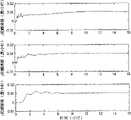
图3为本发明的估计的陀螺仪常值漂移;Fig. 3 is the estimated gyroscope constant value drift of the present invention;
图4为本发明的估计的水平方向上的加速度计零偏;Fig. 4 is the accelerometer zero bias on the estimated horizontal direction of the present invention;
图5为本发明的估计的陀螺仪标度因数误差。Figure 5 is the estimated gyroscope scale factor error of the present invention.
具体实施方式Detailed ways
下面结合附图举例对本发明做更详细地描述:The present invention is described in more detail below in conjunction with accompanying drawing example:
(1)利用全球定位系统GPS确定载体的初始位置参数,将它们装订至导航计算机中;(1) Utilize the global positioning system GPS to determine the initial position parameters of the carrier, and bind them into the navigation computer;
(2)光纤陀螺捷联惯性导航系统进行预热后采集光纤陀螺仪和石英加速度计输出的数据;(2) After preheating, the fiber optic gyroscope strapdown inertial navigation system collects the data output by the fiber optic gyroscope and the quartz accelerometer;
(3)IMU采用8个转停次序为一个旋转周期的转位方案;(3) The IMU adopts an indexing scheme in which 8 rotation-stop sequences are one rotation cycle;
次序1,IMU从A点出发顺时针转动180°到达位置C,停止时间Tt;次序2,IMU从C点出发顺时针转动90°到达位置D,停止时间Tt;次序3,IMU从D点出发逆时针转动180°到达位置B,停止时间Tt;次序4,IMU从B点出发逆时针转动90°到达位置A,停止时间Tt;次序5,IMU从A点出发逆时针转动180°到达位置C,停止时间Tt;次序6,IMU从C点出发逆时针转动90°到达位置B,停止时间Tt;次序7,IMU从B点出发顺时针转动180°到达位置D,停止时间Tt;次序8,IMU从D点出发顺时针转动90°到达位置A,停止时间Tt;IMU按照此转动顺序循环进行。为了有效地对水平方向上的惯性器件偏差在对称位置上进行正负平均,定义水平东向轴上的IMU停顿点p3、p8与p4、p7对称于转轴中心;北向轴上的停顿点p1、p5与p2、p6对称于转轴中心。改进的四位置转停方案仍然是转动角度为180°或90°间隔进行。Sequence 1, IMU starts from point A and rotates 180° clockwise to position C, stop time Tt ;
(4)利用谱条件数法求取IMU四位置转停过程中惯性器件偏差的可观测度;(4) Use the spectral condition number method to obtain the observability of the inertial device deviation during the four-position rotation and stop of the IMU;
考虑求解线性方程组Consider solving a system of linear equations
AX=b,b∈Cn (1)AX=b, b∈Cn (1)
设A∈Cn×n,||·||是一种算子范数,Suppose A∈Cn×n , ||·|| is a kind of operator norm,
称cond(A)为矩阵A(关于求逆或求解线性方程组)的关于算子范数||·||的条件数。常用的是关于p-范数||·||p的条件数,可记作condp(A)。特别,称cond2(A)为谱条件数。We call cond(A) the condition number of the operator norm ||·|| of the matrix A (about inverting or solving linear equations). Commonly used is the condition number of the p-norm ||·||p , which can be denoted as condp (A). In particular, cond2 (A) is called the spectral condition number.
针对离散时变系统:For discrete time-varying systems:
能否由一组观测值Z=[Z0,Z1,....Zk]T求出初始状态X0是系统可观的实质。将系统状态方程带入观测方程得到一组方程:Whether the initial state X0 can be obtained from a set of observed values Z=[Z0 , Z1 , ... Zk ]T is the substantial essence of the system. Bring the system state equation into the observation equation to get a set of equations:
记
则有then there is
OkX0=Z (6)Ok X0 = Z (6)
对于定常系统Fk为常数,Ok就是可观性矩阵。时变系统在采样点上进行观测得到离散时变系统,Fk就是采样周期内的状态转移矩阵Φ(tk+T,tk),因此有For a steady system Fk is a constant, Ok is the observability matrix. The time-varying system is observed at the sampling point to obtain a discrete time-varying system, Fk is the state transition matrix Φ(tk +T, tk ) in the sampling period, so there is
Ok=[HHΦ(t1,t0)…HΦ(tk,t0)]T (7)Ok =[HHΦ(t1 ,t0 )...HΦ(tk ,t0 )]T (7)
设状态是n维的,一次观测量Zk是r维的(r<n),观测阵H的秩为r,至少进行k次观测(kr≥n),才可以求出X0。根据最小二乘法求解状态X0。Assuming that the state is n-dimensional, one observation quantity Zk is r-dimensional (r<n), the rank of the observation array H is r, and X0 can only be obtained by making at least k observations (kr≥n). The state X0 is solved according to the method of least squares.
记

式中,λ为矩阵M的特征值。进一步分析矩阵M的特征值和特征向量,以便确定究竟哪些状态的可观测度较好,哪些状态的可观测度差。将M可酉对角化,记UTMU=Λ,其中Λ=diag(λ1,λ2,...λn),则状态X的可观测度S:In the formula, λ is the eigenvalue of matrix M. Further analyze the eigenvalues and eigenvectors of the matrix M in order to determine which states have better observability and which states have poor observability. M can be unitary diagonalized, write UT MU = Λ, where Λ = diag(λ1 , λ2 ,...λn ), then the observability S of state X:
S=abs(U[λ1,λ2,...,λn]T) (10)S=abs(U[λ1 ,λ2 ,...,λn ]T ) (10)
计算出系统可观测性矩阵M的特征值和特征向量,就可以确定出各个状态的可观测度。By calculating the eigenvalues and eigenvectors of the system observability matrix M, the observability of each state can be determined.
(5)设计无限冲击响应数字高通滤波器(IIR),将导航系下解算出的载体水平速度进行高通滤波处理,滤除导航系下载体速度中的舒勒周期,保留载体由于摇摆和荡运动产生的速度偏差;(5) Design an infinite impulse response digital high-pass filter (IIR), perform high-pass filtering on the horizontal velocity of the carrier calculated by the solution in the navigation system, filter out the Schuler period in the carrier velocity in the navigation system, and retain the carrier due to swaying and swinging motion resulting speed deviation;
(6)根据惯导系统动基座误差方程建立载体系泊状态时的估漂模型,以高通滤波后得到的速度直接作为观测量。利用卡尔曼滤波技术实现旋转捷联惯导系统的现场标定;(6) According to the error equation of the inertial navigation system's moving base, the drift estimation model in the mooring state of the carrier is established, and the velocity obtained after high-pass filtering is used as the observation directly. Using Kalman filter technology to realize the on-site calibration of the rotating strapdown inertial navigation system;
建立以经过高通滤波后的导航系下的水平速度为观测量的卡尔曼滤波模型;Establish a Kalman filter model with the horizontal velocity in the navigation system after high-pass filtering as the observed quantity;
1)建立卡尔曼滤波的状态方程:1) Establish the state equation of the Kalman filter:
用一阶线性微分方程来描述旋转捷联惯导系统的状态误差:The state error of the rotating strapdown inertial navigation system is described by a first-order linear differential equation:
其中X(t)为t时刻系统的状态向量;A(t)和B(t)分别为系统的状态矩阵和噪声矩阵;W(t)为系统噪声向量;Where X(t) is the state vector of the system at time t; A(t) and B(t) are the state matrix and noise matrix of the system respectively; W(t) is the system noise vector;
系统的状态向量为:The state vector of the system is:

系统的白噪声向量为:The white noise vector of the system is:
W=[ax ay ωx ωy ωz 0 0 0 0 0 0 0 0]T (13)W=[ax ay ωx ωy ωz 0 0 0 0 0 0 0 0]T (13)
其中δVe、δVn分别表示东向、北向的速度误差;
系统的状态转移矩阵为:The state transition matrix of the system is:
VE、VN分别表示东向、北向的速度;ωx、ωy、ωz分别表示陀螺的三个输入角速度;ωie表示地球自转角速度;Rm、Rn分别表示地球子午、卯酉曲率半径;L表示当地纬度;fE、fN、fU分别表示为导航坐标系下东向、北向、天向的比力。VE , VN represent the eastward and northward velocities respectively; ωx , ωy , ωz represent the three input angular velocities of the gyroscope; ωie represent the earth's rotation angular velocity; Rm , Rn represent the earth's meridian, Radius of curvature; L represents the local latitude; fE , fN , and fU represent the relative forces in the east, north, and sky directions of the navigation coordinate system, respectively.
2)建立卡尔曼滤波的量测方程:2) Establish the measurement equation of the Kalman filter:
用一阶线性微分方程来描述旋转捷联惯导系统的量测方程如下:The measurement equation of the rotating strapdown inertial navigation system is described by the first-order linear differential equation as follows:
Z(t)=H(t)X(t)+V(t) (21)Z(t)=H(t)X(t)+V(t) (21)
其中:Z(t)表示t时刻系统的量测向量;H(t)表示系统的量测矩阵;V(t)表示系统的量测噪声;Among them: Z(t) represents the measurement vector of the system at time t; H(t) represents the measurement matrix of the system; V(t) represents the measurement noise of the system;
系统量测矩阵为:The system measurement matrix is:
量测量为高通滤波后得到的速度:Quantitative measurement as velocity obtained after high-pass filtering:
Claims (1)


Priority Applications (1)
| Application Number | Priority Date | Filing Date | Title |
|---|---|---|---|
| CN2009100732422ACN101706287B (en) | 2009-11-20 | 2009-11-20 | Rotating strapdown system on-site proving method based on digital high-passing filtering |
Applications Claiming Priority (1)
| Application Number | Priority Date | Filing Date | Title |
|---|---|---|---|
| CN2009100732422ACN101706287B (en) | 2009-11-20 | 2009-11-20 | Rotating strapdown system on-site proving method based on digital high-passing filtering |
Publications (2)
| Publication Number | Publication Date |
|---|---|
| CN101706287A CN101706287A (en) | 2010-05-12 |
| CN101706287Btrue CN101706287B (en) | 2012-01-04 |
Family
ID=42376524
Family Applications (1)
| Application Number | Title | Priority Date | Filing Date |
|---|---|---|---|
| CN2009100732422AExpired - Fee RelatedCN101706287B (en) | 2009-11-20 | 2009-11-20 | Rotating strapdown system on-site proving method based on digital high-passing filtering |
Country Status (1)
| Country | Link |
|---|---|
| CN (1) | CN101706287B (en) |
Families Citing this family (16)
| Publication number | Priority date | Publication date | Assignee | Title |
|---|---|---|---|---|
| CN101893445B (en)* | 2010-07-09 | 2012-02-01 | 哈尔滨工程大学 | Fast Initial Alignment Method for Low Precision Strapdown Inertial Navigation System in Swing State |
| CN102175095B (en)* | 2011-03-02 | 2013-06-19 | 浙江大学 | Strap-down inertial navigation transfer alignment algorithm parallel implementation method |
| CN102435193B (en)* | 2011-12-07 | 2014-01-08 | 浙江大学 | A High Precision Initial Alignment Method for Strapdown Inertial Navigation System |
| CN102538789B (en)* | 2011-12-09 | 2014-07-02 | 北京理工大学 | Rotating method of modulation type inertial navigation system with double-axis rotating continuously |
| CN102865881B (en)* | 2012-03-06 | 2014-12-31 | 武汉大学 | Quick calibration method for inertial measurement unit |
| CN102620735B (en)* | 2012-04-17 | 2013-12-25 | 华中科技大学 | Transposition method of double-shaft rotating type strapdown inertial navigation system for ship |
| CN102788596B (en)* | 2012-08-16 | 2015-04-01 | 辽宁工程技术大学 | Spot calibration method of rotary strap-down inertial navigation system with unknown carrier attitude |
| CN103453917A (en)* | 2013-09-04 | 2013-12-18 | 哈尔滨工程大学 | Initial alignment and self-calibration method of double-shaft rotation type strapdown inertial navigation system |
| CN103604442A (en)* | 2013-11-14 | 2014-02-26 | 哈尔滨工程大学 | Observability analysis method applied to online calibration of strapdown inertial navitation system |
| CN103852085B (en)* | 2014-03-26 | 2016-09-21 | 北京航空航天大学 | A kind of fiber strapdown inertial navigation system system for field scaling method based on least square fitting |
| CN103852086B (en)* | 2014-03-26 | 2016-11-23 | 北京航空航天大学 | A kind of fiber strapdown inertial navigation system system for field scaling method based on Kalman filtering |
| CN104483064A (en)* | 2014-12-29 | 2015-04-01 | 中国海洋石油总公司 | In-situ calibration method for soft steel arm type mooring system stress monitoring device |
| CN104634364B (en)* | 2015-01-29 | 2017-10-03 | 哈尔滨工程大学 | A kind of self-calibrating method of the optic fiber gyroscope graduation factor based on Staircase wave |
| CN106017507B (en)* | 2016-05-13 | 2019-01-08 | 北京航空航天大学 | A kind of used group quick calibrating method of the optical fiber of precision low used in |
| CN110501027B (en)* | 2019-09-16 | 2022-11-18 | 哈尔滨工程大学 | Optimal rotation and stop time distribution method for double-shaft rotating MEMS-SINS |
| CN114689081B (en)* | 2020-12-29 | 2024-12-13 | 北京原子机器人科技有限公司 | GNSS-assisted MINS automatic calibration system and method |
Citations (7)
| Publication number | Priority date | Publication date | Assignee | Title |
|---|---|---|---|---|
| US5719772A (en)* | 1994-09-28 | 1998-02-17 | Aerospatiale Societe Nationale Industrielle | Process and device for minimizing in an inertial measurement system the error due to a perturbing motion in the retrieval of the velocity |
| CN101246022A (en)* | 2008-03-21 | 2008-08-20 | 哈尔滨工程大学 | Two-position Initial Alignment Method for Fiber Optic Gyro Strapdown Inertial Navigation System Based on Filtering |
| CN101377422A (en)* | 2008-09-22 | 2009-03-04 | 北京航空航天大学 | Method for calibrating optimum 24 positions of flexible gyroscope static drift error model |
| CN101514900A (en)* | 2009-04-08 | 2009-08-26 | 哈尔滨工程大学 | Method for initial alignment of a single-axis rotation strap-down inertial navigation system (SINS) |
| CN101514899A (en)* | 2009-04-08 | 2009-08-26 | 哈尔滨工程大学 | Optical fibre gyro strapdown inertial navigation system error inhibiting method based on single-shaft rotation |
| CN100554884C (en)* | 2008-02-28 | 2009-10-28 | 北京航空航天大学 | Optimal eight-position calibration method for flexible gyroscopes |
| CN101571394A (en)* | 2009-05-22 | 2009-11-04 | 哈尔滨工程大学 | Method for determining initial attitude of fiber strapdown inertial navigation system based on rotating mechanism |
- 2009
- 2009-11-20CNCN2009100732422Apatent/CN101706287B/ennot_activeExpired - Fee Related
Patent Citations (7)
| Publication number | Priority date | Publication date | Assignee | Title |
|---|---|---|---|---|
| US5719772A (en)* | 1994-09-28 | 1998-02-17 | Aerospatiale Societe Nationale Industrielle | Process and device for minimizing in an inertial measurement system the error due to a perturbing motion in the retrieval of the velocity |
| CN100554884C (en)* | 2008-02-28 | 2009-10-28 | 北京航空航天大学 | Optimal eight-position calibration method for flexible gyroscopes |
| CN101246022A (en)* | 2008-03-21 | 2008-08-20 | 哈尔滨工程大学 | Two-position Initial Alignment Method for Fiber Optic Gyro Strapdown Inertial Navigation System Based on Filtering |
| CN101377422A (en)* | 2008-09-22 | 2009-03-04 | 北京航空航天大学 | Method for calibrating optimum 24 positions of flexible gyroscope static drift error model |
| CN101514900A (en)* | 2009-04-08 | 2009-08-26 | 哈尔滨工程大学 | Method for initial alignment of a single-axis rotation strap-down inertial navigation system (SINS) |
| CN101514899A (en)* | 2009-04-08 | 2009-08-26 | 哈尔滨工程大学 | Optical fibre gyro strapdown inertial navigation system error inhibiting method based on single-shaft rotation |
| CN101571394A (en)* | 2009-05-22 | 2009-11-04 | 哈尔滨工程大学 | Method for determining initial attitude of fiber strapdown inertial navigation system based on rotating mechanism |
Non-Patent Citations (7)
| Title |
|---|
| JP特开2000-321070A 2000.11.24 |
| 刘峰等.水平初始对准误差对旋转IMU导航系统的精度影响.《中国惯性技术学报》.2008,第16卷(第6期),全文.* |
| 刘百奇等.光纤陀螺IMU的六位置旋转现场标定新方法.《光电工程》.2008,第35卷(第1期),全文.* |
| 王其等.旋转IMU在光纤捷联航姿系统中的应用.《中国惯性技术学报》.2007,第15卷(第3期),全文.* |
| 胡宏灿等.卡尔曼滤波器在导航系统初始对准中的应用.《微电子学与计算机》.2006,第23卷(第2期),全文.* |
| 郭美凤等.激光陀螺惯性导航系统静态校准方法的研究.《中国惯性技术学报》.1997,第5卷(第4期),全文.* |
| 高钟毓.惯性导航系统初始对准与标定最优化方法.《中国惯性技术学报》.2009,第17卷(第1期),全文.* |
Also Published As
| Publication number | Publication date |
|---|---|
| CN101706287A (en) | 2010-05-12 |
Similar Documents
| Publication | Publication Date | Title |
|---|---|---|
| CN101706287B (en) | Rotating strapdown system on-site proving method based on digital high-passing filtering | |
| CN103245360B (en) | Carrier-borne aircraft rotation type strapdown inertial navigation system Alignment Method under swaying base | |
| CN101514899B (en) | Error Suppression Method of Fiber Optic Gyro Strapdown Inertial Navigation System Based on Single-axis Rotation | |
| CN101514900B (en) | A single-axis rotation strapdown inertial navigation system initial alignment method | |
| CN101713666B (en) | Single-shaft rotation-stop scheme-based mooring and drift estimating method | |
| CN103090867B (en) | Error restraining method for fiber-optic gyroscope strapdown inertial navigation system rotating relative to geocentric inertial system | |
| CN100541132C (en) | Mooring fine alignment method for marine fiber optic gyro strapdown attitude system under large misalignment angle | |
| CN101881619B (en) | Ship's inertial navigation and astronomical positioning method based on attitude measurement | |
| CN101672649B (en) | A mooring alignment method for marine optical fiber strapdown system based on digital low-pass filtering | |
| CN103900608B (en) | A kind of low precision inertial alignment method based on quaternary number CKF | |
| CN103090866B (en) | Method for restraining speed errors of single-shaft rotation optical fiber gyro strapdown inertial navigation system | |
| CN106441357B (en) | An Axial Gyro Drift Correction Method for Single-axis Rotating SINS Based on Damping Network | |
| CN105021192A (en) | Realization method of combined navigation system based on zero-speed correction | |
| CN101629826A (en) | Coarse alignment method for fiber optic gyro strapdown inertial navigation system based on single axis rotation | |
| CN101571394A (en) | Method for determining initial attitude of fiber strapdown inertial navigation system based on rotating mechanism | |
| CN102589546B (en) | Optical-fiber strap-down inertial measurement unit reciprocating-type two-position north finding method for inhibiting slope error influence of devices | |
| CN103743413B (en) | Heeling condition modulated is sought northern instrument alignment error On-line Estimation and is sought northern error compensating method | |
| CN107655493A (en) | A kind of position system level scaling methods of optical fibre gyro SINS six | |
| CN102788598B (en) | Error suppressing method of fiber strap-down inertial navigation system based on three-axis rotation | |
| CN104374388A (en) | Flight attitude determining method based on polarized light sensor | |
| CN102768043A (en) | Integrated attitude determination method without external observed quantity for modulated strapdown system | |
| CN106052686A (en) | Full-autonomous strapdown inertial navigation system based on DSPTMS 320F28335 | |
| CN108195400A (en) | The moving alignment method of strapdown micro electro mechanical inertia navigation system | |
| CN106940193A (en) | A kind of ship self adaptation based on Kalman filter waves scaling method | |
| CN102798399A (en) | SINS error inhibiting method based on biaxial rotation scheme |
Legal Events
| Date | Code | Title | Description |
|---|---|---|---|
| C06 | Publication | ||
| PB01 | Publication | ||
| C10 | Entry into substantive examination | ||
| SE01 | Entry into force of request for substantive examination | ||
| C14 | Grant of patent or utility model | ||
| GR01 | Patent grant | ||
| CF01 | Termination of patent right due to non-payment of annual fee | ||
| CF01 | Termination of patent right due to non-payment of annual fee | Granted publication date:20120104 Termination date:20171120 |