CN101697473A - Soft switching-based excitation control system and soft switching-based excitation control method - Google Patents
Soft switching-based excitation control system and soft switching-based excitation control methodDownload PDFInfo
- Publication number
- CN101697473A CN101697473ACN200910188238ACN200910188238ACN101697473ACN 101697473 ACN101697473 ACN 101697473ACN 200910188238 ACN200910188238 ACN 200910188238ACN 200910188238 ACN200910188238 ACN 200910188238ACN 101697473 ACN101697473 ACN 101697473A
- Authority
- CN
- China
- Prior art keywords
- voltage
- links
- switch
- unit
- soft
- Prior art date
- Legal status (The legal status is an assumption and is not a legal conclusion. Google has not performed a legal analysis and makes no representation as to the accuracy of the status listed.)
- Granted
Links
Images


Landscapes
- Inverter Devices (AREA)
- Dc-Dc Converters (AREA)
Abstract
Translated fromChinese
Description
Translated fromChinese技术领域technical field
本发明属于电力电子及其自动化领域,特别涉及一种基于软开关的励磁控制系统及方法。The invention belongs to the field of power electronics and automation thereof, and in particular relates to an excitation control system and method based on a soft switch.
背景技术Background technique
随着自动控制理论、电力电子方法、电子计算机、微电子学等的发展已经进入了一个新的时代,其应用也相应地进入了一个新的高潮。With the development of automatic control theory, power electronic method, electronic computer, microelectronics, etc., it has entered a new era, and its application has also entered a new climax.
目前,励磁控制系统大概出现过以下几种。开始有三相全控桥式整流电路励磁控制系统,这种控制系统其实是一个负反馈的控制系统,系统的稳定运行是工作的首要条件。当发电机并人电网以后,就与电力系统中所有发电机组并联运行。因此,要求发电机的励磁控制系统能对电力系统稳定运行产生有益的影响。但是由于有外界的种种干扰,因此效果不是很好。接着又产生了一种反馈和前馈迭代学习控制算法引入发电机的励磁控制,设计了一种新型的励磁控制器,以调节发电机的功角和机端电压至稳态运行点的极小领域。该控制器采用迭代学习前馈和PID反馈相结合的控制方法,综合了二者的优点,具有在有限时间内迅速精确跟踪期望轨迹,鲁棒性强的特点,虽然控制效果比上一种好,解决了干扰的问题,但是器件以及器件之间存在很大的能量损耗,因此不利于节能。At present, the excitation control system has probably appeared in the following categories. At the beginning, there was a three-phase fully-controlled bridge rectifier circuit excitation control system. This control system is actually a negative feedback control system. The stable operation of the system is the first condition for work. When the generator is connected to the grid, it runs in parallel with all generator sets in the power system. Therefore, the excitation control system of the generator is required to have a beneficial effect on the stable operation of the power system. However, due to various external interferences, the effect is not very good. Then a feedback and feedforward iterative learning control algorithm was introduced into the excitation control of the generator, and a new type of excitation controller was designed to adjust the power angle of the generator and the machine terminal voltage to the minimum of the steady-state operating point field. The controller adopts a control method combining iterative learning feedforward and PID feedback, which combines the advantages of the two, and has the characteristics of rapid and accurate tracking of the desired trajectory within a limited time and strong robustness, although the control effect is better than the previous one. , which solves the problem of interference, but there is a large energy loss between devices and devices, which is not conducive to energy saving.
从60年代开始得到发展和应用的DC-DC PWM功率变换方法是一种硬开关方法。为了使开关电源在高频状态下也能高效率地运行,国内外电力电子界和电源方法界自70年代以来,不断研究开发高频软开关方法。软开关的特点是功率器件在零电压条件下导通(或关断),在零电流条件下关断(或导通)。与硬开关相比,软开关的功率器件在零电压、零电流条件下工作,功率器件开关损耗小。软开关电源的开关器件在开通或关断的过程中,或是加于其上的电压为零,即零电压开关,或是通过开关器件的电流为零,即零电流开关。这种开关方式显著地减小了开关损耗的开关过程中激起的振荡,可以大幅度地提高开关频率,为开关电源小型化、高效率创造了条件。但是,目前的软开关技术,还存在材料和空间浪费,能量损耗过大的问题。The DC-DC PWM power conversion method that has been developed and applied since the 1960s is a hard switching method. In order to make the switching power supply operate efficiently at high frequency, the power electronics and power supply method circles at home and abroad have been researching and developing high-frequency soft switching methods since the 1970s. The characteristic of soft switching is that power devices are turned on (or turned off) under zero voltage conditions and turned off (or turned on) under zero current conditions. Compared with hard switching, soft switching power devices work under zero voltage and zero current conditions, and the switching loss of power devices is small. In the process of turning on or off the switching device of the soft switching power supply, either the voltage applied to it is zero, that is, zero voltage switching, or the current passing through the switching device is zero, that is, zero current switching. This switching method significantly reduces the oscillation caused by the switching loss of the switching process, can greatly increase the switching frequency, and creates conditions for the miniaturization and high efficiency of the switching power supply. However, the current soft switching technology still has the problems of waste of materials and space, and excessive energy loss.
发明内容Contents of the invention
为解决上述技术问题,本发明提供一种基于软开关的励磁控制系统及方法。In order to solve the above technical problems, the present invention provides an excitation control system and method based on soft switching.
本发明系统包括三相电压整流单元,前馈补偿单元、软开关单元、主励磁机、发电机组和占空比控制单元。三相电压整流单元分别与前馈补偿单元和软开关单元相连,软开关单元分别与占空比单元和主励磁机相连,主励磁机分别与前馈补偿单元和发电机组相连,发电机组与占空比控制单元相连。The system of the invention includes a three-phase voltage rectification unit, a feedforward compensation unit, a soft switch unit, a main exciter, a generator set and a duty ratio control unit. The three-phase voltage rectification unit is respectively connected with the feedforward compensation unit and the soft switch unit, the soft switch unit is connected with the duty ratio unit and the main exciter, the main exciter is connected with the feedforward compensation unit and the generator set, and the generator set is connected with the duty ratio unit and the main exciter respectively. The air ratio control unit is connected.
其中,三相电压整流单元包括采集电压端和整流部分,整流部分由6个二极管反并联组成,三相电压经6个二极管不控整流之后变为直流。Among them, the three-phase voltage rectification unit includes a collection voltage terminal and a rectification part, and the rectification part is composed of 6 diodes connected in antiparallel, and the three-phase voltage becomes DC after uncontrolled rectification by 6 diodes.
前馈补偿单元包括开关管VT4、比例器、加法器、电阻和电容。比例器由电容,电阻和第1放大器组成,具体连接关系如下:第7比例电阻的一端作为比例器的输入端,另一端与第1放大器的正端、第6电阻的一端、第8电容的一端相连,第1放大器的输出端与第6电阻的另一端、第8电容的另一端相连,第1放大器的负端接地。前馈补偿单元具体连接关系如下:整流电压与第4开关管的源级相连,比例器的输入端与第4开关管的漏级相连,比例器的输出端即第1放大器的输出端与第3电阻一端相连,第3电阻的另一端与第2放大器的正端、第4电阻的一端、第7电容的一端相连,第2放大器的输出端与第4电阻的另一端、第7电容的另一端相连,第2放大器的输出端与直接控制励磁的电压相连,主电路的电压经过第5电阻的一端与第2放大器的正端相连,第2放大器的负端接地。The feed-forward compensation unit includes a switch tube VT4, a proportioner, an adder, resistors and capacitors. The proportioner is composed of capacitors, resistors and the first amplifier, and the specific connection relationship is as follows: one end of the seventh proportional resistor is used as the input end of the scaler, and the other end is connected to the positive end of the first amplifier, one end of the sixth resistor, and the eighth capacitor. One end is connected, the output end of the first amplifier is connected with the other end of the sixth resistor and the other end of the eighth capacitor, and the negative end of the first amplifier is grounded. The specific connection relationship of the feed-forward compensation unit is as follows: the rectified voltage is connected to the source stage of the fourth switching tube, the input terminal of the scaler is connected to the drain stage of the fourth switching tube, and the output terminal of the scaler is the output terminal of the first amplifier. One end of the 3 resistors is connected, the other end of the third resistor is connected to the positive end of the second amplifier, one end of the fourth resistor, and one end of the seventh capacitor, and the output end of the second amplifier is connected to the other end of the fourth resistor and the end of the seventh capacitor. The other end is connected, the output end of the second amplifier is connected to the voltage that directly controls the excitation, the voltage of the main circuit is connected to the positive end of the second amplifier through one end of the fifth resistor, and the negative end of the second amplifier is grounded.
软开关电路包括主开关管,副开关管、谐振电感和谐振电容。具体连接方式:整流电压Ui正极与第1主开关管的源极相连,第1主开关管反并联第1续流二极管,第1主开关管的漏极与谐振电感Lr一端相连,谐振电感Lr的另一端与第2副开关管的源极相连,第2副开关管的漏极与谐振电容Cr一端相连,谐振电容Cr的另一端连接整流电压负极,在第2副开关管的两端反并联一个第2续流二极管,在第2副开关管与谐振电容Cr串联电路的两端反并联一个续流二极管VD,并且作为励磁电压的输出端,用来控制励磁电流If。The soft switching circuit includes a main switching tube, an auxiliary switching tube, a resonant inductor and a resonant capacitor. Specific connection method: the positive pole of the rectified voltage Ui is connected to the source of the first main switching tube, the first main switching tube is connected in antiparallel to the first freewheeling diode, the drain of the first main switching tube is connected to one end of the resonant inductor Lr, and the resonant inductor Lr The other end of the second switching tube is connected to the source of the second switching tube, the drain of the second switching tube is connected to one end of the resonant capacitor Cr, and the other end of the resonant capacitor Cr is connected to the negative pole of the rectified voltage. A second freewheeling diode is connected in parallel, and a freewheeling diode VD is connected in antiparallel to both ends of the series circuit of the second secondary switch tube and the resonant capacitor Cr, and it is used as the output terminal of the excitation voltage to control the excitation current If.
占空比控制单元包括电压调理电路,倍频电路,供电电路,绝缘栅双极晶体管IGBT驱动电路。其中,占空比单元中的倍频电路、供电电路、电压调理电路和IGBT驱动电路分别与DSP相连。The duty cycle control unit includes a voltage regulation circuit, a frequency multiplication circuit, a power supply circuit, and an IGBT drive circuit of an insulated gate bipolar transistor. Wherein, the frequency multiplying circuit, the power supply circuit, the voltage regulating circuit and the IGBT driving circuit in the duty ratio unit are respectively connected with the DSP.
基于软开关的励磁控制系统的控制方法如下:三相电压接入三相电压整流单元,采集三相电压并对采集到的电压进行整流;经整流单元的电压作为前馈补偿单元的输入信号,经前馈补偿单元输出端将电路损耗补偿给主回路;整流后的交流电压进入软开关单元,经滤波电路滤除整流后的电压波动和电压“毛刺”;滤波之后的电压经主励磁机进发电机组,再进入占空比单元,经电压调理电路进入DSP,DSP运用PID控制算法计算出占空比,通过IGBT驱动电路传递给软开关单元中软开关电路,控制主开关管和副开关管的开通与关断,实现零电流开关、零电压开关。The control method of the excitation control system based on soft switching is as follows: the three-phase voltage is connected to the three-phase voltage rectification unit, the three-phase voltage is collected and the collected voltage is rectified; the voltage of the rectification unit is used as the input signal of the feedforward compensation unit, The circuit loss is compensated to the main circuit through the output terminal of the feed-forward compensation unit; the rectified AC voltage enters the soft switching unit, and the rectified voltage fluctuation and voltage "glitch" are filtered out by the filter circuit; the filtered voltage enters the main circuit through the main exciter. The generator set enters the duty cycle unit, enters the DSP through the voltage conditioning circuit, and the DSP uses the PID control algorithm to calculate the duty cycle, and transmits it to the soft switch circuit in the soft switch unit through the IGBT drive circuit to control the main switch tube and the auxiliary switch tube. Turn on and turn off to realize zero current switching and zero voltage switching.
电路损耗的处理。由于IGBT运行后,在几个IGBT同时导通时,将会产生电能的损耗,在输出端的数值并不能达到要求,因此需要前馈补偿单元加以补偿。由于开关管开关导通其实是几个二极管的同时导通,因此可以通过二极管的导通电压计算损耗。前馈补偿单元输出端将电路损耗补偿给主回路的具体步骤如下:Handling of circuit loss. After the IGBT is running, when several IGBTs are turned on at the same time, there will be a loss of electric energy, and the value at the output end cannot meet the requirements, so a feedforward compensation unit is required to compensate. Since the conduction of the switch tube is actually the simultaneous conduction of several diodes, the loss can be calculated through the conduction voltage of the diodes. The specific steps for compensating the circuit loss to the main circuit at the output of the feedforward compensation unit are as follows:
(1)从三相整流单元采集整流直流电压作为前馈补偿单元的输入;(1) collecting the rectified DC voltage from the three-phase rectification unit as the input of the feedforward compensation unit;
(2)通过二极管的导通电压计算损耗,每个二极管大约0.7V,补偿系数K取值为0.01,通过IGBT(附图4中的VT4)与主回路保持一致;(2) The loss is calculated by the conduction voltage of the diode, each diode is about 0.7V, the compensation coefficient K is 0.01, and the IGBT (VT4 in Figure 4) is consistent with the main circuit;
(3)经过比例器放大一定的倍数;(3) Amplify by a certain multiple through the proportional device;
(4)经过加法器,将数据与输出值相加,补偿到主回路中。(4) After the adder, the data and the output value are added, and compensated to the main loop.
软开关控制方法的原理为通过控制主开关管VT1和副开关管VT2的开通与关断时序来达到PWM控制,零电流开关,零电压开关的目的。The principle of the soft switching control method is to achieve the purpose of PWM control, zero-current switching, and zero-voltage switching by controlling the turn-on and turn-off timing of the main switch tube VT1 and the auxiliary switch tube VT2.
附图2为图1的时序图。将每一阶段的起始时刻定义为该阶段的零时刻,软开关电路在一个周期的工作过程如下:Accompanying drawing 2 is the sequence diagram of Fig. 1. The initial moment of each stage is defined as the zero moment of this stage, and the working process of the soft switching circuit in one cycle is as follows:
(1)t0~t1,谐振电感电流上升阶段(VT1零电流开启)(1) t0~t1, the rising phase of the resonant inductor current (VT1 is turned on with zero current)
在上一周期的结束时刻,主开关管与副开关管均处于关断状态,谐振电感Lr中的电流为0,由续流二极管VD续流,如果不考虑二极管管压降,则VD两端电压为零。在t0时刻开通主开关管VT1,由于谐振电感Lr中的电流不能突变,则VT1实现了零电流开启,而且在开通瞬间,VD处于续流状态,可以认为输入电压完全加在Lr两端,VD自然关断,VT1与VD实现换流。At the end of the previous cycle, both the main switch and the auxiliary switch are in the off state, the current in the resonant inductor Lr is 0, and the freewheeling diode VD continues to flow. If the diode voltage drop is not considered, the two ends of VD The voltage is zero. Turn on the main switch VT1 at time t0 , because the current in the resonant inductor Lr cannot change abruptly, VT1 realizes zero-current turn-on, and at the moment of turn-on, VD is in the continuous flow state, it can be considered that the input voltage is completely added to both ends of Lr, VD is turned off naturally, and VT1 and VD realize commutation.
(2)t1~t2,准谐振阶段(VD零电压关断)(2) t1 ~ t2, quasi-resonance stage (VD zero voltage shutdown)
在t1时刻,VD关断,使VD2与Cr支路开始导通。Lr与Cr谐振,VD2、Cr支路电流下降为零,使VD2关断。从t1~t2,Lr与Cr恰好谐振半个周期。由于VD2与Cr的存在,在VD关断时,其端电压是逐渐升高的,所以VD为零电压关断。At timet1 , VD is turned off, so that the VD2 and Cr branches start to conduct. Lr and Cr resonate, VD2, Cr branch current drops to zero, so that VD2 is turned off. From t1 to t2 , Lr and Cr resonate exactly half a period. Due to the existence of VD2 and Cr, when VD is turned off, its terminal voltage gradually increases, so VD is turned off with zero voltage.
(3)t2~t3,恒流阶段(脉冲调宽PWM工作方式)(3) t2~t3, constant current stage (pulse width modulation PWM working mode)
VD2关断以后,使VD2与Cr支路断开,电路进入PWM工作方式。After VD2 is turned off, disconnect VD2 from the Cr branch, and the circuit enters the PWM working mode.
(4)t3~t4,零电流开关ZCS过渡阶段1(VD1自然导通)(4) t3~t4, zero-current switching ZCS transition stage 1 (VD1 is naturally turned on)
为了给VT1创造零电流关断的条件,在t3时刻使VT2导通,则Lr与Cr再次谐振,Cr放电,VD1自然导通。In order to create a zero-current shutdown condition for VT1, VT2 is turned on at t3, then Lr and Cr resonate again, Cr discharges, and VD1 is naturally turned on.
(5)t4~t6,零电流开关ZCS过渡阶段2(VT1零电流关断)(5) t4~t6, zero-current switch ZCS transition stage 2 (VT1 zero-current shutdown)
VD1一直导通,在这段时间内关断VT1,则实现了主开关的零电流关断,t6时刻,VD1关断。VD1 is turned on all the time, and VT1 is turned off during this period, then the zero-current shutdown of the main switch is realized, and at time t6 , VD1 is turned off.
(6)t6~t7,恒流放电阶段(VD零电压开启)(6) t6~t7, constant current discharge stage (VD zero voltage open)
t6时刻以后,VT1和VD1均关断,Cr独立向负载放电,到t7时刻,续流二极管VD从零电压开始导通。Aftert6 , both VT1 and VD1 are turned off, and Cr independently discharges to the load. Att7 , the freewheeling diode VD starts to conduct from zero voltage.
(7)t7~t9,二极管续流阶段(PWM工作方式)(7) t7~t9, diode freewheeling stage (PWM working mode)
这一阶段与普通的PWM工作方式下的续流阶段相同,VD两端电压为零,在此阶段内关断VT2,则实现了VT2的零电流关断。t9时刻之后,电路进入新的工作周期。This stage is the same as the freewheeling stage in the common PWM working mode, the voltage across VD is zero, and turning off VT2 in this stage realizes the zero-current shutdown of VT2. After timet9 , the circuit enters a new working cycle.
占空比单元实现控制主开关管开关时间,在DSP中完成控制,具体步骤如下:The duty ratio unit controls the switching time of the main switching tube, and the control is completed in the DSP. The specific steps are as follows:
步骤1、DSP各部分进行初始化;
步骤2、对三相电压进行采集,并且通过倍频电路设定采样频率,通过电压调理电路采集电压到AD采样寄存器;
步骤3、然后进入PID控制算法阶段,首先对三相电压进行相序检测;
步骤4、根据电压调理电路的原理将电压还原至实际电压;
步骤5、根据PID控制器方程式,根据我们多次调试的经验,设计出PID参数kp,ki,kd,设定电压稳定值。kp为比例系数,ki为微分系数,kd为积分系数。根据控制算法有:
a=kp+ki+kd;a=kp+ki+kd;
b=-(kp+2*kd);b=-(kp+2*kd);
c=kd;c = kd;
duk=a*ek+b*ek1+c*ek2;duk=a*ek+b*ek1+c*ek2;
ek为第一个周期电压和的平均值与稳定值的差值,ek1为第二个周期电压和的平均值与稳定值的差值,ek2为第三个周期电压和的平均值与稳定值的差值,duk为计算出的总差值。ek is the difference between the average and stable value of the voltage sum in the first cycle, ek1 is the difference between the average and stable value of the voltage sum in the second cycle, and ek2 is the average and stable value of the voltage sum in the third cycle difference, duk is the calculated total difference.
步骤6、利用这个差值作为控制占空比的数值,来控制主开关管的开通与关断;
步骤7、利用软开关电路计算出的主开关管与副开关管的开关相差时间,通过DSP的定时器控制副开关管的开通与关断;
步骤8、此过程为一个动态平衡过程,循环进行。
占空比单元实现控制主开关管开关时间步骤7中所述的通过DSP的定时器控制副开关管的开通与关断,要满足如下条件:使VT1能零电流软关断,必须在VT1关断之前,开通VT2,使电路出现谐振。VT2在t3时刻开通,为保证VT1可靠软关断,需要把VT2的开通时间稍微提前一点,让VT1的关断时刻出现在电流小于0的时候,这时VT1在电流最低点的时候关断。为了使VT2可靠软关断,要确保VT2在C3完全放电之后再关断,因此要在t7的基础上增加一个值,延长VT2的导通时间,将其关断时刻推迟。因此可以算出副开关管开通时刻超前于主开关管的关断时刻和副开关管关断时刻滞后于主开关管的关断时刻,这样就可以根据PID控制器计算出来的主开关管占空比,以主开关管的开通时刻为基准,来决定副开关管的开通和关断时刻以及主开关管的关断时刻。The duty ratio unit realizes the control of the switch time of the main switch tube, as described in
有益效果:Beneficial effect:
本发明研究了一种适合于电机励磁控制的软开关技术。通过控制IGBT的开关时间和CLR的谐振来达到零电流和电压的开关状态,较其他方法,节省了材料与空间,并且有前馈补偿的作用,使得损耗进一步降低。The invention researches a soft switch technology suitable for motor excitation control. By controlling the switching time of the IGBT and the resonance of the CLR to achieve the switching state of zero current and voltage, compared with other methods, it saves materials and space, and has the function of feedforward compensation, which further reduces the loss.
附图说明Description of drawings
图1、为本发明软开关原理图;Fig. 1, is the schematic diagram of soft switch of the present invention;
图2、为本发明软开关原理图的时序图;Fig. 2, is the sequence diagram of soft switch schematic diagram of the present invention;
图3、为本发明实施例系统总体结构框图;Fig. 3 is a block diagram of the overall structure of the system of the embodiment of the present invention;
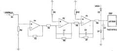
图4、为本发明实施例总电路原理图;Fig. 4, is the general circuit schematic diagram of the embodiment of the present invention;
图中,1、三相电压整流单元;2、滤波电路;3、前馈补偿单元;4、软开关电路;5、软开关单元;6、占空比控制单元;In the figure, 1. Three-phase voltage rectification unit; 2. Filter circuit; 3. Feedforward compensation unit; 4. Soft switching circuit; 5. Soft switching unit; 6. Duty ratio control unit;
图5、为本发明实施例占空比控制单元结构原理图;Fig. 5 is a schematic structural diagram of a duty cycle control unit according to an embodiment of the present invention;
图6、为本发明实施例电压调理电路与DSP芯片电路连接图;Fig. 6 is the connection diagram of the voltage conditioning circuit and the DSP chip circuit of the embodiment of the present invention;
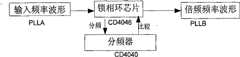
图7(a)、为本发明实施例倍频电路原理图;Fig. 7 (a), is the schematic diagram of the frequency multiplication circuit of the embodiment of the present invention;
图7(b)、为本发明实施例倍频电路与DSP芯片电路连接图;Fig. 7 (b), is the connection diagram of frequency multiplication circuit and DSP chip circuit of the embodiment of the present invention;
图8、为本发明实施例IGBT与DSP芯片电路连接图;Fig. 8 is a circuit connection diagram of an IGBT and a DSP chip according to an embodiment of the present invention;
图9(a)、为本发明实施例供电电路原理图;Figure 9(a) is a schematic diagram of a power supply circuit according to an embodiment of the present invention;
图9(b)、为本发明实施例供电电路与DSP芯片电路连接图;Fig. 9 (b) is the connection diagram of the power supply circuit and the DSP chip circuit of the embodiment of the present invention;
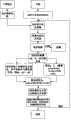
图10、为本发明实施例PID算法流程图;Fig. 10, is the flow chart of PID algorithm of the embodiment of the present invention;
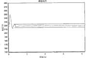
图11、为本发明励磁控制系统波形图。Fig. 11 is a waveform diagram of the excitation control system of the present invention.
具体实施方式Detailed ways
一种基于软开关的励磁控制系统构成如图3所示。三相电压整流单元分别与前馈补偿单元和软开关单元相连,软开关单元分别与前馈补偿单元和主励磁机相连,主励磁机与发电机组相连,发电机组与占空比控制单元相连。其中,占空比单元中的倍频电路、供电电路、电压调理电路和IGBT驱动电路分别与DSP相连。An excitation control system based on soft switching is shown in Figure 3. The three-phase voltage rectification unit is respectively connected with the feedforward compensation unit and the soft switch unit, the soft switch unit is respectively connected with the feedforward compensation unit and the main exciter, the main exciter is connected with the generating set, and the generating set is connected with the duty cycle control unit. Wherein, the frequency multiplying circuit, the power supply circuit, the voltage regulating circuit and the IGBT driving circuit in the duty ratio unit are respectively connected with the DSP.
三相电压整流单元包括采集电压端和整流部分。整流部分由6个二极管反并联组成,用来整流三相电压,作为软开关单元的输入,如附图4中标号1的部分。The three-phase voltage rectification unit includes a collection voltage terminal and a rectification part. The rectification part is composed of 6 diodes in antiparallel connection, used to rectify the three-phase voltage, as the input of the soft switching unit, as shown in the part labeled 1 in Figure 4.
前馈补偿单元如附图4中标号3所示,从主电路采集来的整流后的电压经过比例器,加法器补偿到主电路的输出端,K为补偿的比例系数,一般取值为0.01左右。然后进入一个加法器,将数据与输出的值相加,起到补偿的作用。一般R1=R2=R3=5.1欧。电容C1取值0.01uf,用于滤波作用。在附图2中,R3=R4=R5=5.1千欧,C7=0.01uf。The feed-forward compensation unit is shown as
软开关单元为附图4中标号5的部分,由滤波电路和软开关电路组成。The soft switch unit is the part labeled 5 in the accompanying drawing 4, which is composed of a filter circuit and a soft switch circuit.
滤波电路如附图4中标号2的部分所示,极性电解电容C1用来滤除整流之后大的电压波动,无极性电容C6用来滤除整流之后小的电压“毛刺”,C2和R1构成阻容滤波器。The filter circuit is shown in the part labeled 2 in attached
软开关电路如附图4中标号4的部分所示,包括一个主开关管,一个副开关管、电感和电容。通过控制主开关管和副开关管的开通与关断时序来达到pwm控制,零电流开关,零电压开关的目的。The soft switching circuit, as shown in the part labeled 4 in the accompanying drawing 4, includes a main switching tube, an auxiliary switching tube, an inductor and a capacitor. By controlling the turn-on and turn-off timing of the main switch tube and the auxiliary switch tube, the purpose of pwm control, zero-current switching, and zero-voltage switching is achieved.
占空比控制单元从发电机组采集三相电压,经过电压调理电路进入DSP;倍频电路来设定采样频率,并将结果送给DSP;DSP运用PID控制算法计算出占空比,来控制软开关单元的主开关管;通过主开关管与副开关管的关系,DSP运用自身定时器控制副开关管的时序,如图5所示。The duty cycle control unit collects the three-phase voltage from the generator set, and enters the DSP through the voltage conditioning circuit; the frequency multiplication circuit sets the sampling frequency and sends the result to the DSP; the DSP uses the PID control algorithm to calculate the duty cycle to control the software. The main switching tube of the switching unit; through the relationship between the main switching tube and the secondary switching tube, the DSP uses its own timer to control the timing of the secondary switching tube, as shown in Figure 5.
本实施例中DSP采用TMS320F2812芯片。三相采样电压进入电压调理电路后,输出端与TMS320F2812芯片的ADCINB0端口相连,如图6所示。DSP adopts TMS320F2812 chip in this embodiment. After the three-phase sampling voltage enters the voltage conditioning circuit, the output terminal is connected to the ADCINB0 port of the TMS320F2812 chip, as shown in Figure 6.
如图7(a)和7(b)所示,倍频电路的输入端与A相电压相连,倍频电路的输出端与TMS320F2812芯片的XINT2_ADCSOC(1)引脚相连。As shown in Figure 7(a) and 7(b), the input terminal of the frequency multiplier circuit is connected to the A-phase voltage, and the output terminal of the frequency multiplier circuit is connected to the XINT2_ADCSOC(1) pin of the TMS320F2812 chip.
如图8所示,IGBT驱动电路中的74AC240FC的OE1端口与DSP的TDIRA端口相连,IGBT驱动电路中的74AC240FC的A1端口与DSP的T3PWM_T3CMP端口相连,IGBT驱动电路中的74AC240FC的A2端口与DSP的T4PWM_T3CM端口相连。As shown in Figure 8, the OE1 port of the 74AC240FC in the IGBT drive circuit is connected to the TDIRA port of the DSP, the A1 port of the 74AC240FC in the IGBT drive circuit is connected to the T3PWM_T3CMP port of the DSP, and the A2 port of the 74AC240FC in the IGBT drive circuit is connected to the DSP’s The T4PWM_T3CM port is connected.
如图9(a)和9(b)所示,供电电路与TMS320F2812芯片的电路连接。供电电路与DSP的VDDIO端口、VDD端口相连。As shown in Figure 9(a) and 9(b), the power supply circuit is connected to the circuit of the TMS320F2812 chip. The power supply circuit is connected with the VDDIO port and the VDD port of the DSP.
图10为DSP中PID算法流程图。Fig. 10 is the flow chart of PID algorithm in DSP.
在与某航天集团合作的过程下,利用这个基于软开关技术的励磁控制系统达到了较好的效果。根据附图2中的时序对系统各部件参数作以下设计:In the process of cooperating with an aerospace group, the excitation control system based on soft switching technology has achieved good results. According to the sequence in accompanying drawing 2, the parameters of each component of the system are designed as follows:
为了能够在任何负载情况下都能实现主开关管的零电流开关,谐振电感电流必须能够回零。为了减小谐振电感和谐振电容在谐振工作时对PWM控制产生的影响,应缩短谐振工作时间,即减少附图2中t1~t2和t3~t6的时间,为此必须减小谐振周期Tr,提高谐振频率fs。In order to realize zero-current switching of the main switching tube under any load condition, the resonant inductor current must be able to return to zero. In order to reduce the influence of resonant inductance and resonant capacitor on PWM control during resonant operation, the resonant working time should be shortened, that is, the time of t1~t2 and t3~t6 in Figure 2 should be reduced, so the resonant period Tr must be reduced , increase the resonant frequency fs .
根据本系统发电机额定励磁电流和最大强励倍数来设最大负载电流为Iomak,输入整流电压Ui。副励磁机三相电经整流后,平均电压为Ui。T1最大电流应大于2Iomax,它所承受的最大正向电压为输入电压Ui。开关管反并联二极管VD1的最大电流为最大负载电流4Iomax,所承受的最大反向电压为Ui。如果考虑2倍安全裕量的话,选择电流4Iomax,电压2.5Ui以上的IGBT就能满足要求。续流二极管VD的最大电流为最大负载电流Iomax,最大反向电压为2Ui,同样考虑2倍安全裕量,应选择电流2Iomax,反向电压200V以上的快速二极管。谐振电感最大电流应大于最大负载电流的两倍,因此要选择最大电流大于4Iomax的高频电感。谐振电容上的最大电压为两倍的输入电压,因此要选择最大耐压大于200V的高频无感电容。副开关管VT2所承受的最大正向电压为两倍的输入电压,其反并联二极管所承受的最大反向电压也是两倍的输入电压,以此可以选择合适的IGBT。为了减少器件种类,以方便驱动电路的设计和维护,主IGBT和副IGBT可以用同样的型号。Set the maximum load current asIomak according to the rated excitation current of the system generator and the maximum forced excitation multiple, and input the rectified voltage Ui . The average voltage of the three-phase power of the auxiliary exciter after rectification is Ui . The maximum current of T1 should be greater than 2Iomax , and the maximum forward voltage it bears is the input voltage Ui. The maximum current of the anti-parallel diode VD1 of the switching tube is the maximum load current 4Iomax , and the maximum reverse voltage it bears is Ui. If two times the safety margin is considered, the IGBT with a current of 4Iomax and a voltage of 2.5Ui or more can meet the requirements. The maximum current of the freewheeling diode VD is the maximum load current Iomax , and the maximum reverse voltage is 2Ui. Also considering the double safety margin, a fast diode with a current of 2Iomax and a reverse voltage of 200V or more should be selected. The maximum current of the resonant inductor should be greater than twice the maximum load current, so a high-frequency inductor with a maximum current greater than 4Iomax should be selected. The maximum voltage on the resonant capacitor is twice the input voltage, so it is necessary to select a high-frequency non-inductive capacitor with a maximum withstand voltage greater than 200V. The maximum forward voltage borne by the auxiliary switching tube VT2 is twice the input voltage, and the maximum reverse voltage borne by its anti-parallel diode is also twice the input voltage, so that an appropriate IGBT can be selected. In order to reduce the types of devices and facilitate the design and maintenance of the drive circuit, the same model can be used for the main IGBT and the auxiliary IGBT.
根据本发明的系统和方法进行设计,主电路图附图4中各器件参数为:C1=1000uf,C2=10uf,C3=0.36uf,C4=0.01uf,C5=0.1~0.5uf,C6=0.1uf,C7=0.01uf,C8=0.1uf和R1=R2=R3=R4=R5=5.1千欧,K=0.01,L1=0.0012mH。经综合考虑,本系统中选择的是东芝公司生产的单管IGBT,型号为GT50J325,它的最大电流为50A,耐压600V。要保证软开关的实现,具体效果如图11所示,在有超调的情况下,电压快速的趋于一个稳定值208V,主开关管和副开关管也达到了零电流开关和零电压开关的要求,最大限度的降低电能的损耗,节省了系统的体积。Design according to the system and method of the present invention, the parameters of each device in the accompanying drawing 4 of the main circuit diagram are: C1=1000uf, C2=10uf, C3=0.36uf, C4=0.01uf, C5=0.1~0.5uf, C6=0.1uf , C7=0.01uf, C8=0.1uf and R1=R2=R3=R4=R5=5.1kΩ, K=0.01, L1=0.0012mH. After comprehensive consideration, the single-tube IGBT produced by Toshiba is selected in this system, the model is GT50J325, its maximum current is 50A, and its withstand voltage is 600V. To ensure the realization of soft switching, the specific effect is shown in Figure 11. In the case of overshoot, the voltage quickly tends to a stable value of 208V, and the main switch and the auxiliary switch also achieve zero-current switching and zero-voltage switching. Requirements, minimize the loss of electric energy, save the volume of the system.
Claims (6)
Priority Applications (1)
| Application Number | Priority Date | Filing Date | Title |
|---|---|---|---|
| CN2009101882380ACN101697473B (en) | 2009-10-28 | 2009-10-28 | Soft switching-based excitation control system and soft switching-based excitation control method |
Applications Claiming Priority (1)
| Application Number | Priority Date | Filing Date | Title |
|---|---|---|---|
| CN2009101882380ACN101697473B (en) | 2009-10-28 | 2009-10-28 | Soft switching-based excitation control system and soft switching-based excitation control method |
Publications (2)
| Publication Number | Publication Date |
|---|---|
| CN101697473Atrue CN101697473A (en) | 2010-04-21 |
| CN101697473B CN101697473B (en) | 2011-12-21 |
Family
ID=42142559
Family Applications (1)
| Application Number | Title | Priority Date | Filing Date |
|---|---|---|---|
| CN2009101882380AExpired - Fee RelatedCN101697473B (en) | 2009-10-28 | 2009-10-28 | Soft switching-based excitation control system and soft switching-based excitation control method |
Country Status (1)
| Country | Link |
|---|---|
| CN (1) | CN101697473B (en) |
Cited By (3)
| Publication number | Priority date | Publication date | Assignee | Title |
|---|---|---|---|---|
| CN103457290A (en)* | 2013-08-30 | 2013-12-18 | 山西合创电力科技有限公司 | Intelligent transmission power angle compensation device based on IGBT switch microgrid and large power grid |
| CN104682802A (en)* | 2013-11-28 | 2015-06-03 | 北车大连电力牵引研发中心有限公司 | Excitation control method and excitation control device |
| CN116094374A (en)* | 2021-11-05 | 2023-05-09 | 宁波方太厨具有限公司 | A driving method of a low-noise switched reluctance motor and a cooking machine using the method |
- 2009
- 2009-10-28CNCN2009101882380Apatent/CN101697473B/ennot_activeExpired - Fee Related
Cited By (6)
| Publication number | Priority date | Publication date | Assignee | Title |
|---|---|---|---|---|
| CN103457290A (en)* | 2013-08-30 | 2013-12-18 | 山西合创电力科技有限公司 | Intelligent transmission power angle compensation device based on IGBT switch microgrid and large power grid |
| CN103457290B (en)* | 2013-08-30 | 2015-09-16 | 山西合创电力科技有限公司 | Based on IGBT switch microgrid and bulk power grid intelligent transportation merit angle compensation device |
| CN104682802A (en)* | 2013-11-28 | 2015-06-03 | 北车大连电力牵引研发中心有限公司 | Excitation control method and excitation control device |
| CN104682802B (en)* | 2013-11-28 | 2017-10-13 | 中车大连电力牵引研发中心有限公司 | Excitation control method and device |
| CN116094374A (en)* | 2021-11-05 | 2023-05-09 | 宁波方太厨具有限公司 | A driving method of a low-noise switched reluctance motor and a cooking machine using the method |
| CN116094374B (en)* | 2021-11-05 | 2025-07-08 | 宁波方太厨具有限公司 | Driving method of low-noise switch reluctance motor and food processor adopting same |
Also Published As
| Publication number | Publication date |
|---|---|
| CN101697473B (en) | 2011-12-21 |
Similar Documents
| Publication | Publication Date | Title |
|---|---|---|
| Caracas et al. | Implementation of a high-efficiency, high-lifetime, and low-cost converter for an autonomous photovoltaic water pumping system | |
| CN110365205B (en) | High-efficiency totem-pole bridgeless PFC rectifier control method | |
| CN202034903U (en) | Soft switching pressure rising direct current to direct current (DC-DC) convertor | |
| CN101841165B (en) | Soft switching control method for flyback single-stage photovoltaic grid-connected inverter | |
| CN102403776A (en) | Hybrid power supply system and hybrid power supply method for air conditioner | |
| Hu et al. | Natural boundary transition and inherent dynamic control of a hybrid-mode-modulated dual-active-bridge converter | |
| CN101312330A (en) | High voltage power source of resonant transformer | |
| Li et al. | Working principle analysis and control algorithm for bidirectional DC/DC converter. | |
| Zhou et al. | Impedance editing based second harmonic current reduction for new energy access system | |
| CN113783418A (en) | Low-input-current-ripple high-gain soft-switching direct-current converter | |
| CN112311222A (en) | An improved bridgeless DBPFC converter and control method based on composite predictive current control | |
| CN103595257B (en) | A kind of isolated soft switching step down DC converter and control method thereof | |
| Rajakumari et al. | Comparative analysis of DC-DC converters | |
| CN114785144A (en) | LLC resonant converter parameter optimization method, PI control method and device | |
| Jabbari | Unified analysis of switched-resonator converters | |
| CN110445387A (en) | A kind of topological structure and control method of forming and capacity dividing power supply | |
| CN101697473B (en) | Soft switching-based excitation control system and soft switching-based excitation control method | |
| CN209375466U (en) | A Wide Gain LLC Resonant Converter | |
| CN111525828A (en) | Control method of bidirectional isolation type resonant power converter based on virtual synchronous motor | |
| CN106655862B (en) | A kind of non-isolation type inverter and its control method inhibiting ripple | |
| Chen et al. | Analysis and design of LLC converter based on SiC MOSFET | |
| CN112542978B (en) | Motor driving system based on bidirectional staggered parallel DC-DC inverter | |
| CN103956903B (en) | LC parallel resonances are depressured the control method of DC/DC conversion device | |
| CN101264546A (en) | A main power system of high frequency inverter arc welding power supply | |
| CN105226986A (en) | A kind of inverter and control method thereof eliminating the pulsation of input side secondary power |
Legal Events
| Date | Code | Title | Description |
|---|---|---|---|
| C06 | Publication | ||
| PB01 | Publication | ||
| C10 | Entry into substantive examination | ||
| SE01 | Entry into force of request for substantive examination | ||
| C14 | Grant of patent or utility model | ||
| GR01 | Patent grant | ||
| CF01 | Termination of patent right due to non-payment of annual fee | Granted publication date:20111221 Termination date:20151028 | |
| EXPY | Termination of patent right or utility model |