CN101693347A - Rotating cutter on-line measurement method based on image processing - Google Patents
Rotating cutter on-line measurement method based on image processingDownload PDFInfo
- Publication number
- CN101693347A CN101693347ACN200910188042ACN200910188042ACN101693347ACN 101693347 ACN101693347 ACN 101693347ACN 200910188042 ACN200910188042 ACN 200910188042ACN 200910188042 ACN200910188042 ACN 200910188042ACN 101693347 ACN101693347 ACN 101693347A
- Authority
- CN
- China
- Prior art keywords
- cutter
- profile
- point
- tool
- image
- Prior art date
- Legal status (The legal status is an assumption and is not a legal conclusion. Google has not performed a legal analysis and makes no representation as to the accuracy of the status listed.)
- Granted
Links
- 238000000691measurement methodMethods0.000titleclaimsabstractdescription7
- 238000012545processingMethods0.000titleabstractdescription7
- 239000000284extractSubstances0.000claimsabstractdescription4
- 238000001514detection methodMethods0.000claimsdescription7
- 238000000034methodMethods0.000claimsdescription5
- 238000000605extractionMethods0.000claimsdescription3
- 239000007787solidSubstances0.000claimsdescription2
- 238000003860storageMethods0.000claimsdescription2
- 238000005259measurementMethods0.000abstractdescription6
- 238000003708edge detectionMethods0.000abstract1
- 238000003754machiningMethods0.000abstract1
- 238000005516engineering processMethods0.000description5
- 238000005520cutting processMethods0.000description2
- 238000011161developmentMethods0.000description2
- 230000000694effectsEffects0.000description2
- 238000004519manufacturing processMethods0.000description2
- 238000011160researchMethods0.000description2
- 238000010586diagramMethods0.000description1
- 238000003801millingMethods0.000description1
- 230000003068static effectEffects0.000description1
Images

Landscapes
- Length Measuring Devices By Optical Means (AREA)
Abstract
Translated fromChinese
Description
Technical field:
The present invention relates to the Computerized Numerical Control processing technology field, exactly it is a kind of revolution class cutter on-machine measurement method of handling based on image.
Background technology:
Numeric Control Technology is called for short " numerical control ".Application of numerical control technology has brought revolutionary variation not only for traditional manufacturing industry, make manufacturing industry become industrialized symbol, and along with the continuous development of Numeric Control Technology and the expansion of application, he is to the important effect of development play more and more of some important industries (IT, automobile, light industry, medical treatment etc.) of national economy.
In digital control processing, need compensate cutter parameters, be necessary to develop high accuracy, high efficiency cutter parameters on-machine measurement system.In numerous measuring methods, be more intuitively based on the detection of image, and have real-time, accuracy, plurality of advantages such as widely applicable.Cutter generally can be divided into square contour cutter (as lathe tool, boring cutter) and revolution class cutter (as milling cutter, drill bit) according to its profile, in the present cutter image detecting system of studying, is the research to lathe tool mostly.Revolution class cutter is because cutting edge mostly is helical form, shaft section profile at the circumferencial direction diverse location changes, and single cutter image can not react the envelope profile of revolution class cutter, and adds man-hour, revolution class cutter is done to rotate continuously, and its processing result is determined by cutter real work profile.At present, the research of turning round class cutter on-machine measurement is also relatively lagged behind, the effect of Ying Yonging also is not very desirable in practice, and can not on-machine measurement.As China Patent No. " 200420034226.5 ", name is called the utility model of " a kind of precision cutting tool measurement mechanism of the CCD of employing digital camera ", China Patent No. " 200410022253.5 ", name is called the patent of invention of " a kind of precision measurement method of static cutter image ", all can not on-machine measurement revolution class cutter.
Summary of the invention:
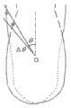
The objective of the invention is: a kind of revolution class cutter on-machine measurement method of handling based on image is provided.The high resolution CCD camera absorbs the shaft section image of diverse location cutter continuously, again each image is carried out rim detection, and extracts profile point, is stored in the array.Then a plurality of profiles are superposeed, obtain turning round the work profile of class cutter.Calculate the actual geometric parameter of cutter at last and carry out the sub-pix spline-fit.Adding the TP point of cutter in man-hour, is in all images profile point, in this direction from center cutter point farthest.Because profile is the combination of discrete point, so the stack of image outline, ask exactly in the minute angle excursion, with the maximum point of the distance at center.In the accompanying drawing 2, the profile that dotted outline and dotted outline are respectively ball endmills in phase angle [alpha]=0 and α=π/3 o'clock, round dot and side's point are respectively the points on two profiles.In minute angle excursion [θ, θ+Δ θ], round dot analogy point distance center point is far away, and therefore the profile point after the stack is a round dot.Solid outline is represented the profile that two cutter instantaneous axis cross section profile stack backs form among the figure.In cutter rotated a circle, n profile stack formed the envelope profile of revolution class cutter.
The present invention can directly measure the parameter of the cutter of processing on Digit Control Machine Tool, and specially at revolution class cutter, cutter picture by several outs of phase that superpose, try to achieve the envelope profile and the tool geometrical parameter of revolution class cutter, can be widely used in cutter compensation, based on the fields such as digital control processing of cutter real work profile.
Description of drawings:
Fig. 1 is a ball endmill diverse location profile of the present invention.
Fig. 2 is a profile stacking method of the present invention.
Fig. 3 is a workflow diagram of the present invention.
The specific embodiment:
The present invention adopts following technical scheme to realize:
Step 1, revolution class cutter are done to slowly run on machine tool chief axis, and the high resolution CCD camera absorbs the shaft section image of diverse location cutter continuously, is input to computer by USB interface.As shown in Figure 1.
Step 2, each image that step 1 is obtained carry out rim detection, and the extraction profile point, calculate the line of each marginal point-centre of form and the sine and the cosine value of symmetrical center line angle theta, then all marginal points are sorted from small to large according to angle, can obtain an array [r, c]T, according to profile order, the pixel coordinate of storage profile point, this array length is the number of marginal point.
Step 3, the image outline that step 2 is obtained superpose.Ask exactly in the minute angle excursion, with the set apart from maximum point at center, as shown in Figure 2.In cutter rotated a circle, n profile stack formed the envelope profile of revolution class cutter.
In the formula, n is the picture number that obtains in cutter rotates a circle, and R is a tool radius, and σ is the discontinuous caused error of taking pictures.
The actual geometric parameter of step 4, calculating cutter.When measuring radius, on circular arc, choose some points, utilize least square fitting to go out the circular arc equation, draw arc radius.When measuring length, on the straightway of profile, get a little, utilize least square fitting to go out linear equation, obtain the distance from the point of a knife to the chuck on rectilinear direction then.Repeatedly measure, average.
Step 5, the profile point that extracts through rim detection can navigate to the Pixel-level precision, and the edge of actual cutter may be positioned between pixel and the pixel.Adopt B spline-fit method, simulate sub-pixel cutter real work profile.Each pixel dimension 3.3 μ m * 3.3 μ m in the image, the sub-pixel positioning precision can reach 0.2~0.5 pixel.
Claims (1)
1. revolution class cutter on-machine measurement method of handling based on image, it is characterized in that: measuring method is as follows:
Step 1, revolution class cutter are done to slowly run on machine tool chief axis, the high resolution CCD camera absorbs the shaft section image of diverse location cutter continuously, again each image is carried out rim detection, and extraction profile point, be stored in the array, then a plurality of profiles superposeed, obtain turning round the envelope profile of class cutter, the actual geometric parameter that will calculate cutter at last carries out the sub-pix spline-fit, is input to computer by USB interface;
Step 2, each image that step 1 is obtained carry out rim detection, and the extraction profile point, calculate the line of each marginal point-centre of form and the sine and the cosine value of symmetrical center line angle theta, then all marginal points are sorted from small to large according to angle, can obtain an array [r, c]T, according to profile order, the pixel coordinate of storage profile point, this array length is the number of marginal point;
Step 3, the image outline that step 2 is obtained superpose, and ask exactly in the minute angle excursion, and with the set apart from maximum point at center, in cutter rotated a circle, n profile stack formed the envelope profile of revolution class cutter,
The actual geometric parameter of step 4, calculating cutter, when measuring radius, on circular arc, choose some points, utilize least square fitting to go out the circular arc equation, draw arc radius, when measuring length, on the straightway of profile, get a little, utilize least square fitting to go out linear equation, obtain the distance from the point of a knife to the chuck on rectilinear direction then, repeatedly measure, average;
Step 5, the profile point that extracts through rim detection can navigate to the Pixel-level precision, and the edge of actual cutter may be positioned between pixel and the pixel.Adopt B spline-fit method, simulate sub-pixel cutter TP.Each pixel dimension 3.3 μ m * 3.3 μ m in the image, the sub-pixel positioning precision can reach 0.2~0.5 pixel;
The TP point that adds the cutter in man-hour, be in all images profile point, in this direction from center cutter point farthest, because profile is the combination of discrete point, therefore the stack of image outline, ask exactly in the minute angle excursion, with the maximum point of the distance at center, the profile that dotted outline and dotted outline are respectively ball endmills in phase angle [alpha]=0 and α=π/3 o'clock, round dot and side's point are respectively the points on two profiles, in minute angle excursion [θ, θ+Δ θ], round dot analogy point distance center point is far away, therefore the profile point after the stack is a round dot, solid outline is represented the profile that two cutter instantaneous axis cross section profile stack backs form, and in cutter rotated a circle, n profile stack formed the envelope profile of revolution class cutter.
Priority Applications (1)
| Application Number | Priority Date | Filing Date | Title |
|---|---|---|---|
| CN 200910188042CN101693347B (en) | 2009-10-23 | 2009-10-23 | An image processing-based on-machine measurement method for rotary tools |
Applications Claiming Priority (1)
| Application Number | Priority Date | Filing Date | Title |
|---|---|---|---|
| CN 200910188042CN101693347B (en) | 2009-10-23 | 2009-10-23 | An image processing-based on-machine measurement method for rotary tools |
Publications (2)
| Publication Number | Publication Date |
|---|---|
| CN101693347Atrue CN101693347A (en) | 2010-04-14 |
| CN101693347B CN101693347B (en) | 2013-05-15 |
Family
ID=42092371
Family Applications (1)
| Application Number | Title | Priority Date | Filing Date |
|---|---|---|---|
| CN 200910188042Expired - Fee RelatedCN101693347B (en) | 2009-10-23 | 2009-10-23 | An image processing-based on-machine measurement method for rotary tools |
Country Status (1)
| Country | Link |
|---|---|
| CN (1) | CN101693347B (en) |
Cited By (14)
| Publication number | Priority date | Publication date | Assignee | Title |
|---|---|---|---|---|
| CN102091974A (en)* | 2010-11-11 | 2011-06-15 | 西安交通大学苏州研究院 | Installing and adjusting method for high-speed lathe machining property on-machine measuring device |
| CN102538696A (en)* | 2010-12-17 | 2012-07-04 | 尖点科技股份有限公司 | Detection method of machining tool |
| CN103175848A (en)* | 2013-02-05 | 2013-06-26 | 厦门大学 | Relative centrifugal force (RCF) type online milling cutter blade breakage detection method |
| CN103180094A (en)* | 2010-10-22 | 2013-06-26 | 株式会社牧野铣床制作所 | Tool dimension measuring method and measuring device |
| CN103737428A (en)* | 2014-01-22 | 2014-04-23 | 南京工程学院 | System and method for measuring dynamic deformation of high-speed numerically-controlled machine tool |
| CN105241389A (en)* | 2015-10-12 | 2016-01-13 | 贵州大学 | Machine visual sense based detection system for blunt round radius of cutting edge of milling cutter |
| CN106907995A (en)* | 2017-03-20 | 2017-06-30 | 深圳市美思美科智能科技股份有限公司 | A kind of cutter automatic detection system |
| CN108943086A (en)* | 2018-07-18 | 2018-12-07 | 南通超达装备股份有限公司 | A kind of automobile slush moulding epidermis reduction special equipment |
| CN109345500A (en)* | 2018-08-02 | 2019-02-15 | 西安交通大学 | A method for calculating the position of the tool nose point of a machine tool based on machine vision |
| CN110332897A (en)* | 2019-08-08 | 2019-10-15 | 珠海博明视觉科技有限公司 | A kind of compensation model of raising system to roundlet measurement accuracy |
| CN112269352A (en)* | 2020-10-23 | 2021-01-26 | 新代科技(苏州)有限公司 | Cutting machine control system and control method thereof |
| CN115847187A (en)* | 2023-02-27 | 2023-03-28 | 成都大金航太科技股份有限公司 | Real-time monitoring system for deep and narrow groove turning |
| CN115930823A (en)* | 2022-11-23 | 2023-04-07 | 苏州小孔成像光电科技有限公司 | Cutter section detection and fitting method and system |
| CN116079138A (en)* | 2023-03-14 | 2023-05-09 | 广东盈通纸业有限公司 | Automatic control method of cylinder punching machine |
Citations (3)
| Publication number | Priority date | Publication date | Assignee | Title |
|---|---|---|---|---|
| US20010017699A1 (en)* | 2000-01-08 | 2001-08-30 | Joachim Egelhof | Method and measuring device for measuring a rotary tool |
| CN1680072A (en)* | 2004-04-08 | 2005-10-12 | 电子科技大学 | A Precise Measuring Method of Static Tool Image |
| CN101549468A (en)* | 2009-04-24 | 2009-10-07 | 北京邮电大学 | Image-based on-line detection and compensation system and method for cutting tools |
- 2009
- 2009-10-23CNCN 200910188042patent/CN101693347B/ennot_activeExpired - Fee Related
Patent Citations (3)
| Publication number | Priority date | Publication date | Assignee | Title |
|---|---|---|---|---|
| US20010017699A1 (en)* | 2000-01-08 | 2001-08-30 | Joachim Egelhof | Method and measuring device for measuring a rotary tool |
| CN1680072A (en)* | 2004-04-08 | 2005-10-12 | 电子科技大学 | A Precise Measuring Method of Static Tool Image |
| CN101549468A (en)* | 2009-04-24 | 2009-10-07 | 北京邮电大学 | Image-based on-line detection and compensation system and method for cutting tools |
Cited By (22)
| Publication number | Priority date | Publication date | Assignee | Title |
|---|---|---|---|---|
| CN103180094A (en)* | 2010-10-22 | 2013-06-26 | 株式会社牧野铣床制作所 | Tool dimension measuring method and measuring device |
| CN103180094B (en)* | 2010-10-22 | 2015-10-21 | 株式会社牧野铣床制作所 | The assay method of tool sizes and determinator |
| US9453716B2 (en) | 2010-10-22 | 2016-09-27 | Makino Milling Machine Co., Ltd. | Method of measurement and apparatus for measurement of tool dimensions |
| CN102091974A (en)* | 2010-11-11 | 2011-06-15 | 西安交通大学苏州研究院 | Installing and adjusting method for high-speed lathe machining property on-machine measuring device |
| CN102091974B (en)* | 2010-11-11 | 2012-11-28 | 西安交通大学苏州研究院 | Installing and adjusting method for high-speed lathe machining property on-machine measuring device |
| CN102538696A (en)* | 2010-12-17 | 2012-07-04 | 尖点科技股份有限公司 | Detection method of machining tool |
| CN103175848A (en)* | 2013-02-05 | 2013-06-26 | 厦门大学 | Relative centrifugal force (RCF) type online milling cutter blade breakage detection method |
| CN103737428A (en)* | 2014-01-22 | 2014-04-23 | 南京工程学院 | System and method for measuring dynamic deformation of high-speed numerically-controlled machine tool |
| CN103737428B (en)* | 2014-01-22 | 2016-03-02 | 南京工程学院 | A kind of High Speed NC Machine Tools dynamic deformation measuring system and measuring method |
| CN105241389A (en)* | 2015-10-12 | 2016-01-13 | 贵州大学 | Machine visual sense based detection system for blunt round radius of cutting edge of milling cutter |
| CN106907995A (en)* | 2017-03-20 | 2017-06-30 | 深圳市美思美科智能科技股份有限公司 | A kind of cutter automatic detection system |
| CN108943086A (en)* | 2018-07-18 | 2018-12-07 | 南通超达装备股份有限公司 | A kind of automobile slush moulding epidermis reduction special equipment |
| CN108943086B (en)* | 2018-07-18 | 2024-05-03 | 南通超达装备股份有限公司 | Special equipment for weakening automobile slush molding epidermis |
| CN109345500A (en)* | 2018-08-02 | 2019-02-15 | 西安交通大学 | A method for calculating the position of the tool nose point of a machine tool based on machine vision |
| CN110332897A (en)* | 2019-08-08 | 2019-10-15 | 珠海博明视觉科技有限公司 | A kind of compensation model of raising system to roundlet measurement accuracy |
| CN112269352A (en)* | 2020-10-23 | 2021-01-26 | 新代科技(苏州)有限公司 | Cutting machine control system and control method thereof |
| CN112269352B (en)* | 2020-10-23 | 2022-03-01 | 新代科技(苏州)有限公司 | Cutting machine control system and control method thereof |
| CN115930823A (en)* | 2022-11-23 | 2023-04-07 | 苏州小孔成像光电科技有限公司 | Cutter section detection and fitting method and system |
| CN115847187A (en)* | 2023-02-27 | 2023-03-28 | 成都大金航太科技股份有限公司 | Real-time monitoring system for deep and narrow groove turning |
| CN115847187B (en)* | 2023-02-27 | 2023-05-05 | 成都大金航太科技股份有限公司 | Real-time monitoring system for deep and narrow groove turning |
| CN116079138A (en)* | 2023-03-14 | 2023-05-09 | 广东盈通纸业有限公司 | Automatic control method of cylinder punching machine |
| CN116079138B (en)* | 2023-03-14 | 2023-10-20 | 广东盈通纸业有限公司 | Automatic control method of cylinder punching machine |
Also Published As
| Publication number | Publication date |
|---|---|
| CN101693347B (en) | 2013-05-15 |
Similar Documents
| Publication | Publication Date | Title |
|---|---|---|
| CN101693347B (en) | An image processing-based on-machine measurement method for rotary tools | |
| CN105159228B (en) | 5-shaft linkage numerical control lathe realizes five axle scaling methods of RTCP functions | |
| CN103148827B (en) | A kind of gear wheel measuring method based on joint arm measuring machine | |
| CN101992407B (en) | Error identifying method and error identifying program of machine | |
| CN103105152B (en) | A kind of Gear Processing Analysis of Surface Topography method based on simulation of gear machining model | |
| CN102049731B (en) | Method for precisely measuring and processing profile of disc cam | |
| CN103028909B (en) | The method of processing thin-walled semi-circular part | |
| CN104990487B (en) | A kind of nonopiate gyroaxis axle center bias measurement method based on linkage error analysis | |
| CN103273379A (en) | Method for detecting linkage accuracy of C-shaft of multi-shaft linkage double-pendulum numerical control milling machine | |
| CN101424512A (en) | Method for detecting radial motion error of high speed principal axis by multi-ring coincidence three-point method | |
| CN111536876B (en) | A method for in-situ measurement of sealing surface of triple eccentric butterfly valve | |
| CN112100810B (en) | A method for predicting the multi-axis milling force of a flat-bottom milling cutter | |
| CN102252617A (en) | Morphology registration analysis-based method for detecting precision of precise main shaft rotation | |
| CN102744648A (en) | Error measurement and separation method of rotating table of numerically-controlled machine tool | |
| CN103639842A (en) | Intelligent machining positioning system and method for radial drilling machine | |
| CN104985483A (en) | Method for improving on-machine measuring precision of pitch deviation of large-sized gears | |
| CN110794766A (en) | Quick identification method for measuring perpendicularity error of numerical control machine tool based on ball arm instrument | |
| CN105522183A (en) | Method for processing dynamic inclined hole | |
| CN103759939B (en) | Large speed ratio high-accuracy speed reduction unit drive error testing experiment table and method of testing thereof | |
| CN103438844B (en) | Based on the complex curved surface part localization method of particle cluster algorithm | |
| CN104266570A (en) | Station axis precision measuring and adjusting method for disc type multi-station machine tool | |
| CN105783845A (en) | Tooth profile measuring method of numerical control gear grinding machine on-machine measuring system | |
| Pham et al. | A manufacturing model of an end mill using a five-axis CNC grinding machine | |
| CN104889516A (en) | Electrical discharge machining method of three-dimensional space hole | |
| CN106944680A (en) | A kind of disc type gear is molded roll flute adaptive machining method |
Legal Events
| Date | Code | Title | Description |
|---|---|---|---|
| C06 | Publication | ||
| PB01 | Publication | ||
| C10 | Entry into substantive examination | ||
| SE01 | Entry into force of request for substantive examination | ||
| C14 | Grant of patent or utility model | ||
| GR01 | Patent grant | ||
| CF01 | Termination of patent right due to non-payment of annual fee | Granted publication date:20130515 Termination date:20141023 | |
| EXPY | Termination of patent right or utility model |