CN101690677B - Focused Ultrasound Therapy Combined Array Element Phased Array and Multi-focus Shear Wave Imaging System - Google Patents
Focused Ultrasound Therapy Combined Array Element Phased Array and Multi-focus Shear Wave Imaging SystemDownload PDFInfo
- Publication number
- CN101690677B CN101690677BCN2009100242847ACN200910024284ACN101690677BCN 101690677 BCN101690677 BCN 101690677BCN 2009100242847 ACN2009100242847 ACN 2009100242847ACN 200910024284 ACN200910024284 ACN 200910024284ACN 101690677 BCN101690677 BCN 101690677B
- Authority
- CN
- China
- Prior art keywords
- array
- array element
- focus
- combined
- transducer
- Prior art date
- Legal status (The legal status is an assumption and is not a legal conclusion. Google has not performed a legal analysis and makes no representation as to the accuracy of the status listed.)
- Expired - Fee Related
Links
- 238000003384imaging methodMethods0.000titleclaimsabstractdescription39
- 238000002560therapeutic procedureMethods0.000titleabstractdescription12
- 238000002604ultrasonographyMethods0.000titledescription29
- 230000005284excitationEffects0.000claimsabstractdescription25
- 239000011159matrix materialSubstances0.000claimsabstractdescription7
- 238000009826distributionMethods0.000claimsdescription41
- 238000010008shearingMethods0.000claimsdescription11
- 239000000523sampleSubstances0.000claimsdescription8
- 230000001225therapeutic effectEffects0.000claimsdescription7
- 238000006073displacement reactionMethods0.000claimsdescription4
- 238000012544monitoring processMethods0.000claimsdescription4
- 238000005086pumpingMethods0.000claims1
- 238000012163sequencing techniqueMethods0.000claims1
- 238000000034methodMethods0.000description35
- 230000005855radiationEffects0.000description27
- 238000010586diagramMethods0.000description12
- 210000001519tissueAnatomy0.000description12
- 238000003491arrayMethods0.000description9
- 238000001356surgical procedureMethods0.000description6
- 206010028980NeoplasmDiseases0.000description3
- 230000008901benefitEffects0.000description3
- 238000004364calculation methodMethods0.000description3
- 230000002068genetic effectEffects0.000description3
- 230000003902lesionEffects0.000description3
- 238000005457optimizationMethods0.000description3
- 238000011160researchMethods0.000description3
- 230000015572biosynthetic processEffects0.000description2
- 230000006378damageEffects0.000description2
- 238000001514detection methodMethods0.000description2
- 238000002091elastographyMethods0.000description2
- 238000005516engineering processMethods0.000description2
- 230000008569processEffects0.000description2
- 230000004044responseEffects0.000description2
- 238000002099shear wave elastographyMethods0.000description2
- 230000000451tissue damageEffects0.000description2
- 231100000827tissue damageToxicity0.000description2
- 238000012285ultrasound imagingMethods0.000description2
- 229920001817AgarPolymers0.000description1
- 239000008272agarSubstances0.000description1
- 230000009286beneficial effectEffects0.000description1
- 230000004071biological effectEffects0.000description1
- 230000005540biological transmissionEffects0.000description1
- 210000004204blood vesselAnatomy0.000description1
- 210000000988bone and boneAnatomy0.000description1
- 239000002131composite materialSubstances0.000description1
- 230000007547defectEffects0.000description1
- 230000007850degenerationEffects0.000description1
- 238000013461designMethods0.000description1
- 238000010336energy treatmentMethods0.000description1
- 238000001415gene therapyMethods0.000description1
- 238000010438heat treatmentMethods0.000description1
- 230000006872improvementEffects0.000description1
- 238000009434installationMethods0.000description1
- 238000004519manufacturing processMethods0.000description1
- 238000013507mappingMethods0.000description1
- 239000000463materialSubstances0.000description1
- 239000000203mixtureSubstances0.000description1
- 230000017074necrotic cell deathEffects0.000description1
- 210000005036nerveAnatomy0.000description1
- 238000013021overheatingMethods0.000description1
- 238000012545processingMethods0.000description1
- 230000008439repair processEffects0.000description1
- 210000004872soft tissueAnatomy0.000description1
- 238000001308synthesis methodMethods0.000description1
- 238000009210therapy by ultrasoundMethods0.000description1
- 230000003685thermal hair damageEffects0.000description1
- 239000013598vectorSubstances0.000description1
Images


Landscapes
- Surgical Instruments (AREA)
- Ultra Sonic Daignosis Equipment (AREA)
Abstract
Description
Translated fromChinese技术领域technical field
本发明属于生物医学仪器技术领域,涉及一种聚焦超声非侵入性外科手术治疗的设备,具体涉及一种组合阵元相控阵换能器,应用于多焦点聚焦超声治疗和辐射力成像激励;以及采用该组合阵元相控阵换能器的多焦点平面剪切波成像系统。The invention belongs to the technical field of biomedical instruments, and relates to equipment for focused ultrasound non-invasive surgical treatment, in particular to a combined array element phased array transducer, which is applied to multi-focus focused ultrasound treatment and radiation force imaging excitation; And a multi-focus planar shear wave imaging system using the combined array element phased array transducer.
背景技术Background technique
聚焦超声手术(Focused ultrasound surgery,FUS)是将超声能量聚焦在人体深部目标组织,以达到精确选定热损伤目标组织而丝毫不伤害临近正常组织的治疗方式,目前主要应用于肿瘤的非侵入性治疗。聚焦超声手术属于治疗超声(Therapeutic ultrasound)的高能量治疗,治疗超声中较低能量的治疗,如骨修复、超声波导入(Sonophoresis)、声致穿孔(Sonoporation)和基因治疗(Gene therapy)等的聚焦治疗和生物效应也是目前的国际前沿研究。Focused ultrasound surgery (FUS) is a treatment method that focuses ultrasonic energy on the deep target tissue of the human body to precisely select the target tissue for thermal damage without harming the adjacent normal tissue. It is currently mainly used in non-invasive tumor treatment. treat. Focused ultrasound surgery belongs to the high-energy treatment of therapeutic ultrasound (Therapeutic ultrasound), and the treatment of lower energy in therapeutic ultrasound, such as focusing on bone repair, sonophoresis, sonoporation and gene therapy. Treatment and biological effects are also current international frontier research.
在聚焦超声治疗的研究中,相控阵换能器作为治疗的主要技术手段已得到基本认可。相控阵比起单阵元有诸多优势,如:(a)相控阵不仅能达到单阵元的焦点声强,更重要的是它具有电子控制焦点扫描;(b)相控阵适合灵活、多变的单焦点治疗,以及同时多点的聚焦模式同单阵元单焦点相比可增大单次治疗的聚焦区体积,大大减少治疗时间,加快了聚焦超声手术的治疗速度;(c)相控阵可采用子阵方式有效避开一些声传播障碍物进行无创治疗,如避开肋骨的治疗等;(d)相控阵可以校正由于超声穿越颅骨时带来的焦点偏移和栅瓣。In the research of focused ultrasound therapy, phased array transducer has been basically recognized as the main technical means of treatment. Compared with single array elements, phased array has many advantages, such as: (a) phased array can not only achieve the focal sound intensity of single array element, but more importantly, it has electronically controlled focus scanning; (b) phased array is suitable for flexible , changeable single-focus treatment, and multi-point focus mode at the same time can increase the volume of the focus area of a single treatment compared with the single focus of a single array unit, greatly reduce the treatment time, and speed up the treatment speed of focused ultrasound surgery; (c ) The phased array can effectively avoid some sound propagation obstacles by using the sub-array method for non-invasive treatment, such as avoiding the treatment of ribs; (d) the phased array can correct the focus shift and grid valve.
为了获得大的声强增益,一般采用具有几何焦区的球冠(凹球面)作为相控阵治疗换能器的外形,阵元排布在球面上;阵元的形式有环形、圆形、矩形和扇蜗形等形式。发明人Umemura、发明名称为“Ultrasonic irradiationsystem”的美国专利US4,865,042较早于1989年披露了球冠相控阵换能器,也就是球面环形相控阵和球面扇蜗形相控阵;其控制驱动方式能够产生焦平面上环形对称分布的多焦点,而驱动方法只做相位控制,即相角调制,而各阵元的幅度保持一样。In order to obtain a large sound intensity gain, a spherical crown (concave spherical surface) with a geometric focal area is generally used as the shape of the phased array therapeutic transducer, and the array elements are arranged on the spherical surface; the array elements are in the form of ring, circle, Rectangular and fan-shaped and other forms. Inventor Umemura, U.S. Patent No. 4,865,042 named "Ultrasonic irradiation system" disclosed the spherical crown phased array transducer earlier in 1989, that is, the spherical annular phased array and the spherical fan spiral phased array; its control The driving method can produce multi-focal points with circular symmetrical distribution on the focal plane, while the driving method only performs phase control, that is, phase angle modulation, and the amplitude of each array element remains the same.
在相控阵聚焦方法方面有以色列InSightec-TxSonics.Ltd.公司申请的专利名称为“System and method for creating longer necrosed volumes using a phasedarray focused ultrasound”的美国专利US 6,613,004B1以及专利名称为“利用相控阵聚焦超声系统增加坏死体积的系统和方法”的相应的中国发明专利01813606.0,其中采用了全阵等幅和变迹的聚焦方式交替工作,增大了相控阵聚焦超声手术中组织损伤的治疗体积,克服了仅用变迹所生成的组织损伤体积易造成焦前区过热的现象。以色列InSightec-TxSonics.Ltd.公司的专利名称是“减少相控阵聚焦系统中次热点的系统和方法”的另一中国发明专利01808265.3,以及专利名称是“Systems and methods for controlling a phasedarray focused ultrasound system”的美国专利US 6,506,171B1和专利名称是“用于控制相控阵聚焦超声系统的系统方法”的相应的中国发明专利01819664.0,披露了在聚焦超声发射时周期性地变动发射频率,实际上是增加驱动信号的带宽,来有效地抑制聚焦超声相控阵所产生的次焦点;还披露了在系统幅度和相位控制上采用数字电位器和数字合成法产生的正弦波矢量作为相控阵的驱动信号的方法。In terms of the phased array focusing method, there is the US patent US 6,613,004B1 and the patent title "Using Phase Control The corresponding Chinese invention patent 01813606.0 of "system and method for increasing necrosis volume by array focused ultrasound system", which adopts full-array equal-amplitude and apodization focusing methods to work alternately, which increases the treatment of tissue damage in phased-array focused ultrasound surgery The volume overcomes the phenomenon that the tissue damage volume generated only by apodization is likely to cause overheating of the front focal area. Israel InSightec-TxSonics.Ltd.'s patent name is another Chinese invention patent 01808265.3, "Systems and methods for controlling a phased array focused ultrasound system" and the patent name is "Systems and methods for controlling a phased array focused ultrasound system "U.S. Patent US 6,506,171B1 and the corresponding Chinese invention patent 01819664.0 whose patent title is "System Method for Controlling Phased Array Focused Ultrasound System" discloses that the transmission frequency is periodically changed when the focused ultrasound is emitted, which is actually Increase the bandwidth of the driving signal to effectively suppress the subfocus produced by the focused ultrasonic phased array; also discloses the use of digital potentiometers and digital synthesis methods to generate sine wave vectors as the drive for the phased array in the system amplitude and phase control Signal method.
国内相控阵的发明专利情况为:上海交通大学申请的发明专利2007100451792、专利名称为“相控阵聚焦超声多模式热场形成方法”和发明专利ZL200610023637.8、专利名称为“相控阵聚焦超声的大焦域形成方法”;两发明专利中披露了采用圆形108阵元安装于球冠面的相控阵,工作方式采用旋转交替焦点方式来均匀加热和增加热场治疗体积,焦点的控制是采用矩阵伪逆和热场代价函数优化的。陈亚珠等2006年公开的发明专利,申请号2005101111028.3“加热深部肿瘤病灶的大焦域相控聚焦系统”中披露相控阵系统通道相位和幅度控制方法和系统构造。中国科学院申请的发明专利200610114747.5,专利名称为“一种相控聚焦超声波源装置”中披露了采用圆形阵元安装于球冠中的相控阵阵元结构。西安交通大学的发明专利ZL200610096069.x、专利名称为“球面相控阵聚焦超声换能器的声场焦点模式驱动控制方法”,其中披露了常规的球面换能器阵元中心对齐的矩形阵元分布方式,还披露了球面矩形阵元的声场计算并结合多焦点的遗传算法优化的模式控制方法进行3维多焦点的控制;另一发明专利ZL200610096068.5、专利名称为“上百阵元复合材料球面相控阵高强度聚焦超声治疗系统”,其中披露了适合驱动大于100阵元的分层分布结构的各对应阵元通道相位和幅度独立控制的系统构架和B超图像引导的治疗系统组成;该系统可实施相控阵的各3维焦点模式的控制和手术过程的引导及治疗规划等。Domestic phased array invention patents are as follows: the invention patent 2007100451792 applied by Shanghai Jiaotong University, the patent name is "phased array focused ultrasonic multi-mode thermal field formation method" and the invention patent ZL200610023637.8, the patent name is "phased array focusing Ultrasonic large focal region formation method”; the two invention patents disclose a phased array with circular 108 array elements installed on the spherical crown surface, and the working method adopts the rotating and alternating focal point method to uniformly heat and increase the thermal field treatment volume. Control is optimized using a matrix pseudoinverse and a thermal field cost function. Invention patent published by Chen Yazhu et al. in 2006, application number 2005101111028.3 "Large focal domain phased focusing system for heating deep tumor lesions", discloses phase and amplitude control method and system structure of phased array system channel. The invention patent 200610114747.5 applied by the Chinese Academy of Sciences, the patent name is "a phased focusing ultrasonic source device", discloses a phased array element structure using a circular array element installed in a spherical crown. Xi'an Jiaotong University's invention patent ZL200610096069.x, the patent name is "Sound Field Focus Mode Drive Control Method for Spherical Phased Array Focused Ultrasonic Transducer", which discloses the distribution of rectangular array elements aligned with the centers of conventional spherical transducer array elements method, and also disclosed the sound field calculation of spherical rectangular array elements combined with the multi-focus genetic algorithm optimization mode control method for 3-dimensional multi-focus control; another invention patent ZL200610096068. "Spherical Phased Array High-Intensity Focused Ultrasound Therapy System", which discloses a system architecture suitable for driving a layered distribution structure of more than 100 array elements, independently controlling the phase and amplitude of each corresponding array element channel, and a B-ultrasound image-guided treatment system composition; The system can implement the control of each 3-dimensional focus mode of the phased array, the guidance of the operation process and the treatment planning, etc.
目前,治疗换能器的探头尺寸一般较大,直径约在3-20cm之间,为的是获得大的声强增益;然而对相控阵换能器理论上要完全不产生栅瓣,则阵元中心间距(或阵元尺寸)要等于或小于半个超声波波长。由此推得对于大增益的治疗换能器,就会要求阵元数大于10000,因而随之而来的驱动通道数也应大于10000。对现有技术做上万阵元相控阵在技术上是可行的,但要上万通道的驱动控制会开销太大且过于复杂,是不可行的。一般治疗相控阵换能器的阵元尺寸都大于1个波长,矩形阵元尺寸约几个波长,因此,焦点扫描仅在几何焦点的一个较小区域内不会产生栅瓣,并且声强符合治疗要求,我们把这个区域叫做焦点扫描区域(或叫焦区)。对于相同直径参数的换能器,阵元尺寸越小则焦点扫描区域越大。对当前的高强度聚焦超声(HIFU)治疗和低强度聚焦超声治疗应用需求来说,希望有大的焦点扫描区、尽量少的驱动通道数,这样可得到焦点电子扫描更大的三维区域而无需附加机械扫描装置。而常规的阵元中心对齐的换能器焦点扫描区域就有限。At present, the probe size of the therapeutic transducer is generally large, with a diameter of about 3-20cm, in order to obtain a large sound intensity gain; The distance between the centers of the array elements (or the size of the array elements) must be equal to or less than half the ultrasonic wavelength. From this, it can be deduced that for a large-gain therapeutic transducer, the number of array elements is required to be greater than 10,000, and thus the number of driving channels should also be greater than 10,000. It is technically feasible to make a phased array with tens of thousands of array elements for the existing technology, but the drive control of tens of thousands of channels will be too expensive and too complicated, and it is not feasible. Generally, the size of the array element of the phased array transducer for treatment is larger than 1 wavelength, and the size of the rectangular array element is about several wavelengths. Therefore, the focus scanning only does not produce grating lobes in a small area of the geometric focus, and the sound intensity In line with the treatment requirements, we call this area the focus scanning area (or focal area). For transducers with the same diameter parameters, the smaller the array element size, the larger the focal scanning area. For the current application requirements of high-intensity focused ultrasound (HIFU) therapy and low-intensity focused ultrasound therapy, it is desirable to have a large focus scanning area and as few drive channels as possible, so that a larger three-dimensional area can be obtained by focusing electronically scanning without Additional mechanical scanning device. However, the focus scanning area of the conventional array element center-aligned transducer is limited.
发明内容Contents of the invention
本发明的一个目的就是提供一种组合阵元相控阵换能器,在不改变常规相控阵换能器驱动通道数的情况下,通过新的组合阵元分布和相关驱动方式实现显著扩大焦点扫描区体积,以克服现有常规阵元中心对齐的换能器的焦点扫描区有限的不足。One object of the present invention is to provide a phased array transducer with combined array elements, which can achieve significant expansion through new distribution of combined array elements and related driving methods without changing the number of driving channels of conventional phased array transducers. The volume of the focus scanning area is used to overcome the limitation of the focus scanning area of the conventional array element center-aligned transducer.
本发明的另一个目的就是提供一种多焦点平面剪切波成像系统,将组合阵元相控阵换能器扩大焦点扫描区体积的特性应用于新的弹性成像中的声辐射力激励成像方式中。Another object of the present invention is to provide a multi-focus plane shear wave imaging system, which applies the feature of expanding the volume of the focal scanning area of the combined array element phased array transducer to the acoustic radiation force excitation imaging method in the new elastography middle.
为了达到上述目的,本发明采用以下技术方案予以实现。In order to achieve the above object, the present invention adopts the following technical solutions to achieve.
(1)一种组合阵元相控阵换能器,应用于多焦点聚焦超声治疗和辐射力成像激励,其特征在于:组合阵元是2×2或3×3基阵阵元以球面矩形形式分行紧凑布置而成,每个组合阵元中的所有基阵阵元在电气上并联,共用一个功率驱动通道;相邻组合阵元的中心至少在一个方向上相互错开一个基阵阵元距离,每一组合阵元对应一个功率驱动通道的相位和幅值,在不增加有效工作阵元面积和不增加功率驱动通道的情况下,获得无栅瓣的多焦点分布在比常规相控阵更大的半径圆上,其中常规相控阵在外径112mm时多焦点分布在半径R=2.7mm的圆上。(1) A combined array element phased array transducer, which is applied to multi-focus focused ultrasound therapy and radiation force imaging excitation, is characterized in that: the combined array element is a 2×2 or 3×3 basic array element with a spherical rectangle The form is compactly arranged in rows, and all the basic array elements in each combined array element are electrically connected in parallel and share a power drive channel; the centers of adjacent combined array elements are staggered by a basic array element distance in at least one direction , each combined array element corresponds to the phase and amplitude of a power drive channel, without increasing the effective working area of the array element and without increasing the power drive channel, the multi-focus distribution without grating lobes can be obtained in a much smaller area than the conventional phased array On a circle with a large radius, the conventional phased array multi-focus is distributed on a circle with a radius R=2.7mm when the outer diameter is 112mm.
技术方案(1)的进一步改进和特点在于:换能器的球面中心有用于安装治疗时进行图像引导监控的B超探头孔;组合阵元对称分布于球面上。这种组合阵元分布与驱动方式在不增加有效工作阵元面积和不增加功率驱动通道的情况下,显著扩大焦点扫描区域;获得比常规相控阵扩大约10倍的无栅瓣焦点扫描区域体积。The further improvement and features of the technical solution (1) are: the center of the spherical surface of the transducer has a B-ultrasound probe hole for image-guided monitoring during installation and treatment; the combined array elements are symmetrically distributed on the spherical surface. This combination of array element distribution and driving method significantly expands the focus scanning area without increasing the effective working array element area and power drive channel; obtains a grating-lobe-free focus scanning area that is about 10 times larger than conventional phased arrays volume.
对于驱动阵元尺寸大于半波长的相控阵要达到扩展无栅瓣焦点扫描区的目的,可采用阵元中心错开的阵元分布方式,它不仅对球面矩形相控阵适用,而且对其它阵元和曲面的如扇蜗形和圆形等相控阵的分布同样适用,这时错开的方式不是行间,而是圆环间。For phased arrays whose driving element size is larger than half wavelength, to achieve the purpose of expanding the focal scanning area without grating lobes, the array element distribution method with the center of the array element staggered can be adopted, which is not only suitable for spherical rectangular phased arrays, but also for other arrays. The distribution of phased arrays such as fan-shaped and circular arrays of elements and curved surfaces is also applicable. At this time, the way of staggering is not between rows, but between rings.
(2)一种多焦点平面剪切波成像系统,该系统分为两路:一路是采用技术方案(1)所述组合阵元相控阵换能器的多焦点辐射力剪切波激励子系统,另一路是剪切波B超射频图像获取和剪切波弹性成像子系统;主控计算机控制激励子系统与成像子系统的时序控制,先将激励信号按每个功率驱动通道所需的相位和幅值发送到分层分布控制器,通过控制256通道功率驱动器驱动256组合阵元的各基阵阵元生成沿声轴的多焦点的辐射力剪切波;然后激励子系统与成像子系统按发出的时序控制信号触发剪切波振动的射频数据及图像采集:B超成像探头将辐射力平面剪切波的振动位移通过全数字化B超,再通过射频数据得到剪切波振动的射频序列图像送到主控计算机,然后经过实时处理剪切波振动的射频序列图像得到组织剪切波传播速度CT、剪切波弹性模量μ和剪切粘性系数μ2进行成像。(2) A multi-focus planar shear wave imaging system, the system is divided into two paths: one path is the multi-focus radiation force shear wave exciter using the combined array element phased array transducer described in the technical solution (1) system, the other is the shear wave B-ultrasound radio frequency image acquisition and shear wave elastography subsystem; the main control computer controls the timing control of the excitation subsystem and the imaging subsystem, and first drives the excitation signal according to the required power of each power channel. The phase and amplitude are sent to the layered distribution controller, which drives each of the 256 combined array elements by controlling the 256-channel power driver to generate multi-focal radiation force shear waves along the acoustic axis; then the excitation subsystem and the imaging subsystem The system triggers the RF data and image acquisition of shear wave vibration according to the timing control signal sent out: the B-ultrasound imaging probe passes the vibration displacement of the plane shear wave of the radiation force through the fully digital B-ultrasound, and then obtains the RF data of the shear wave vibration through the RF data. The sequence images are sent to the main control computer, and then the radio frequency sequence images of shear wave vibration are processed in real time to obtain tissue shear wave propagation velocity CT , shear wave elastic modulus μ and shear viscosity coefficient μ2 for imaging.
附图说明Description of drawings
下面结合附图和具体实施方式对本发明做进一步详细说明。The present invention will be described in further detail below in conjunction with the accompanying drawings and specific embodiments.
图1作为参考,图示为常规球面矩形阵元相控阵治疗换能器的阵元结构原理图,各阵元中心为对齐的排布,换能器外径112mm、中心孔径38mm、方形阵元宽6.9mm、曲率半径125mm、工作频率1.3MHz;As a reference, Figure 1 shows the principle diagram of the array element structure of a conventional spherical rectangular array element phased array therapy transducer. The center of each array element is aligned. Element width 6.9mm, radius of curvature 125mm, working frequency 1.3MHz;
图2是本发明组合阵元球面相控阵阵元排布结构原理图,图示为1284-组合阵元相控阵((a)为主视图,(b)为俯视图,换能器外径112mm、中心孔径38mm、曲率半径125mm、工作频率1.3MHz,612基阵,基阵阵元宽3.4mm);Fig. 2 is a schematic diagram of the array element arrangement structure of the combined array element spherical phased array of the present invention. 112mm, central aperture 38mm, curvature radius 125mm, operating frequency 1.3MHz, 612 arrays, array element width 3.4mm);
图3是本发明组合阵元球面相控阵阵元排布结构原理图,图示为1289-组合阵元相控阵(换能器外径112mm、中心孔径38mm、曲率半径125mm、工作频率1.3MHz,1516基阵,基阵阵元宽2.2mm);Figure 3 is a schematic diagram of the array element arrangement structure of the combined array element spherical phased array of the present invention, shown as a 1289-combined array element phased array (transducer outer diameter 112mm, central aperture 38mm, radius of curvature 125mm, operating frequency 1.3 MHz, 1516 base array, array element width 2.2mm);
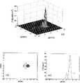
图4是图1常规球面相控阵在焦点(0,4.2,125)mm处的声强分布图,(a)焦平面声强分布,(b)x-y平面声强等高图,(c)y投影面声强分布;Fig. 4 is the sound intensity distribution map of the conventional spherical phased array in Fig. 1 at the focal point (0, 4.2, 125) mm, (a) sound intensity distribution in the focal plane, (b) sound intensity contour map in the x-y plane, (c) y projection surface sound intensity distribution;
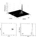
图5是本发明1284-组合阵元相控阵在焦点(0,9,125)mm处的声强分布图,(a)焦平面声强分布,(b)x-y平面声强等高图,(c)y投影面声强分布;Fig. 5 is the sound intensity distribution diagram of the 1284-combined array element phased array of the present invention at the focal point (0,9,125) mm, (a) focal plane sound intensity distribution, (b) x-y plane sound intensity contour map, (c) Sound intensity distribution on the y projection surface;
图6是本发明1289-组合阵元相控阵在焦点(0,9,125)mm处的声强分布图,(a)焦平面声强分布,(b)x-y平面声强等高图,(c)y投影面声强分布;Fig. 6 is the sound intensity distribution diagram of the 1289-combined array element phased array of the present invention at the focal point (0,9,125) mm, (a) focal plane sound intensity distribution, (b) x-y plane sound intensity contour map, (c) Sound intensity distribution on the y projection surface;
图7(a)和(b)是图1常规球面相控阵产生的适形“C”形(5焦点)焦点模式的声强分布图,图7(c)和(d)为本发明1284-组合阵元相控阵产生的适形“C”形(7焦点)焦点模式的声强分布比较图;Figure 7 (a) and (b) are the sound intensity distribution diagrams of the conformal "C" shape (5 focal points) focus mode produced by the conventional spherical phased array in Figure 1, and Figure 7 (c) and (d) are 1284 of the present invention -Comparison diagram of the sound intensity distribution of the conformal "C"-shaped (7 focus) focus mode produced by the combined array element phased array;
图8是本发明组合阵元相控阵产生的适形多焦点声强分布,(a)是128-4组合阵元相控阵产生的适形“C”形焦点模式的声强等高图,(b)是2564-组合阵元相控阵产生的适形“C”形焦点模式的声强等高图,(c)是2564-组合阵元相控阵产生的13焦点“S”形焦点模式的声强等高图,(d)是2564-组合阵元相控阵产生的16焦点方形焦点模式的声强等高图;Fig. 8 is the conformal multi-focus sound intensity distribution produced by the combined array element phased array of the present invention, (a) is the sound intensity contour map of the conformal "C" shaped focus mode produced by the 128-4 combined array element phased array , (b) is the sound intensity contour map of the conformal "C"-shaped focus mode produced by the 2564-combined array element phased array, (c) is the 13-focus "S" shape produced by the 2564-combined array element phased array The sound intensity contour map of the focus mode, (d) is the sound intensity contour map of the 16 focus square focus mode produced by the 2564-combined array element phased array;
图9是以本发明组合阵元治疗相控阵激励产生多焦点辐射力平面剪切波,与此同时用全数字化B超获取射频图像并得到剪切图像的系统原理图;Fig. 9 is a system principle diagram of generating multi-focus radiation force plane shear wave by combining array element treatment phased array excitation of the present invention, and at the same time acquiring radio frequency image and shearing image with fully digital B-ultrasound;
图10是本发明2564-组合阵元相控阵在声轴方向(声传播方向)产生多焦点辐射力激励平面剪切波的声强等高图:(a)声轴方向上两分离焦点、(b)声轴方向上两紧凑焦点、(c)声轴方向上3分离焦点、(d)声轴方向上两对两焦点加强型声强等高图;Fig. 10 is the sound intensity contour map of the 2564-combined array element phased array of the present invention in the sound axis direction (sound propagation direction) to generate multi-focal radiation force excitation plane shear waves: (a) two separated focal points in the sound axis direction, (b) two compact foci in the direction of the sound axis, (c) three separated foci in the direction of the sound axis, (d) two pairs of two foci enhanced sound intensity contours in the direction of the sound axis;
图11是本发明图9激励成像系统得到的组织中硬块的剪切弹性模量参数图像。Fig. 11 is the shear elastic modulus parameter image of the hard mass in the tissue obtained by the excitation imaging system in Fig. 9 of the present invention.
具体实施方式Detailed ways
一般情况下,如发明专利ZL200510096069.x和ZL200510096068.5采用的阵元分布见图1(我们称为常规阵元分布),相邻两行的阵元2中心对齐。过于整齐的阵元排布可能是易产生栅瓣的根源之一。对于2维圆形阵元以往有一些办法如随机分布阵元或采取稀疏阵来抑制栅瓣,这样做会增大换能器的声窗面积。本发明专利采用紧凑的阵元分布不会增加声窗面积,具体的思路是采用组合阵元中心不对齐而错开分布的方式,这样的结果可扩大无栅瓣的区域体积。In general, as shown in Figure 1 for the array element distribution used in invention patents ZL200510096069.x and ZL200510096068.5 (we call it a conventional array element distribution), the
本发明的具体实施方式(1)见图2,换能器3的外径112mm、中心孔径38mm、曲率半径125mm、工作频率1.3HMz,为了方便对比,图2的这些参数和图1完全一样。图1阵元宽度6.9mm、共128阵元。在图2中先将图1换能器的每一个阵元划分为4个阵元,做成一个612阵元的基阵,基阵阵元宽度3.4mm;然后将相邻的4个阵元(基阵阵元)组合成1个组合阵元,称为4-组合阵元4,即2×2阵元组合阵元,每个组合阵元4的中心用小圆点标出(见图2);1个组合阵元的4个阵元在电气连接上是并联的由一个通道驱动,也就是1个4-组合阵元由1个通道的相位和幅度信号驱动。最重要的分布是相邻两行的组合阵元中心不是对齐的,而是移动了(错开)1个基阵的位置(见图2),这样的组合阵元分布是能扩展扫描焦点区的主要因素;总的4-组合阵元数是128,称1284-组合阵,用128通道功率驱动器驱动(同图1的128通道功率驱动数相同),图2中中心孔5用于安装B超探头,128驱动信号从接头6连到换能器组合阵元。Specific embodiments of the present invention (1) see Fig. 2, the external diameter 112mm of
本发明的具体的实施方式(2)见图3,换能器3的外径112mm、中心孔径38mm、曲率半径125mm、工作频率1.3HMz,为了方便对比,图3的这些参数和图2、图1完全一样。在图3中先将图1换能器的每一个阵元划分为9个阵元,做成一个1516阵元的基阵,基阵阵元宽度2.2mm;然后将相邻的9个阵元(基阵阵元)组合成1个组合阵元,称为9-组合阵元,即3×3阵元组合阵元,每个组合阵元的中心用小圆点标出(见图3);1个组合阵元的9个阵元在电气连接上是并联的由一个通道驱动,也就是1个9-组合阵元由1个通道的相位和幅度信号驱动。与1284-组合阵一样,相邻两行的组合阵元中心移动(错开)1个基阵的位置(见图3),因而能扩展扫描焦点区;总的9-组合阵元数是128,称1289-组合阵,用128通道功率驱动器驱动。Concrete embodiment (2) of the present invention is shown in Fig. 3, and the external diameter 112mm of
在现有高技术条件下,可在1-3压电材料球壳上分(切)割出较小的整齐紧凑分布相同尺寸的矩形基阵,再由相邻基阵阵元组合成组合阵元。Under the existing high-tech conditions, smaller rectangular arrays of the same size can be cut (cut) on the 1-3 piezoelectric material spherical shell, and then the adjacent array elements can be combined to form a combined array. Yuan.
组合阵的多焦点模式驱动控制方法同常规相控阵的驱动控制方法一样:每一组合阵元对应一个通道的相位和幅值,128个通道的幅值和相位要能够独立控制。采用授权的发明专利ZL200510096096.x的球面阵元声场计算联合该专利的遗传算法多焦点优化的联合算法逆向得到所设计的多焦点模式所对应的各阵元驱动信号的相位和幅值进行控制。The multi-focus mode driving control method of the combined array is the same as that of the conventional phased array: each combined array element corresponds to the phase and amplitude of a channel, and the amplitude and phase of the 128 channels must be independently controllable. Using the authorized invention patent ZL200510096096.x to calculate the sound field of the spherical array element combined with the patented genetic algorithm multi-focus optimization joint algorithm to reversely obtain the phase and amplitude of each array element drive signal corresponding to the designed multi-focus mode for control.
以下关于声场结果的实施条件为:相控阵换能器施加的总声功率为200W、组织声衰减系数0.02Np/cm/MHz。The following implementation conditions for the sound field results are: the total sound power applied by the phased array transducer is 200W, and the tissue sound attenuation coefficient is 0.02Np/cm/MHz.
对于图1的对齐方式常规阵,我们可得到单焦点3维扫描的无栅瓣区域为径向:8.4mm、轴向:18mm,也就是无栅瓣焦点扫描区体积为:8.4×8.4×18mm3,图4示出常规球面相控阵在极限位置焦点(0,4.2,125)mm处的声强分布图,焦点尺寸1.75×1.75×18mm3;这些结果将作为后面实施例结果的对照。For the conventional alignment array in Figure 1, we can obtain that the grating-lobe-free area of single-focus 3D scanning is radial: 8.4mm, axial: 18mm, that is, the volume of the grating-lobe-free focus scanning area is: 8.4×8.4×18mm3. Figure 4 shows the sound intensity distribution diagram of the conventional spherical phased array at the focal point (0, 4.2, 125) mm at the limit position, and the focal point size is 1.75×1.75×18mm3 ; these results will be used as a comparison with the results of the following examples.
实施例1:Example 1:
对于图2本发明的球面1284-组合阵元相控阵,在与图1的128通道驱动数、换能器外径、曲率半径和频率完全一样的情况下:得到单焦点3维扫描的无栅瓣区域为径向:18mm、轴向:40mm,无栅瓣焦点扫描区体积为:18×18×40mm3,图5示出1284-组合球面相控阵在极限位置焦点(0,9,125)mm处的声强分布图,焦点尺寸1.75×1.75×18mm3。For the spherical 1284-combined array element phased array of the present invention in Fig. 2, under the same situation as the 128-channel driving number, transducer outer diameter, curvature radius and frequency in Fig. 1: obtain the no-matter of single-focus 3-dimensional scanning The grating lobe area is radial: 18mm, axial direction: 40mm, and the volume of the focus scanning area without grating lobes is: 18×18×40mm3 . Figure 5 shows that the 1284-combined spherical phased array is at the limit position focus (0, 9, 125)mm sound intensity distribution diagram, focal spot size 1.75×1.75×18mm3 .
因而得到的结论是:1284-组合阵3(图2)可以获得比常规阵(图1)扩大约10倍的无栅瓣焦点扫描区域体积。Therefore, it is concluded that the 1284-combined array 3 (Fig. 2) can obtain a focus scanning area volume without grating lobes which is about 10 times larger than that of the conventional array (Fig. 1).
实施例2:Example 2:
对于图3本发明的球面1289-组合阵元相控阵,在与图1的128通道驱动数、换能器外径、曲率半径和频率完全一样的情况下:得到单焦点3维扫描的无栅瓣区域为径向:18mm、轴向:40mm,无栅瓣焦点扫描区体积为:18×18×40mm3,图6示出1289-组合球面相控阵在极限位置焦点(0,9,125)mm处的声强分布图,焦点尺寸1.75×1.75×18mm3,焦点峰值比1284-组合阵略高。For the spherical 1289-combined array element phased array of the present invention in Fig. 3, under the same situation as the 128-channel driving number, transducer outer diameter, curvature radius and frequency in Fig. 1: obtain the no-nonsense single-focus 3-dimensional scanning The grating lobe area is radial: 18mm, axial direction: 40mm, and the volume of the focus scanning area without grating lobes is: 18×18×40mm3 . Figure 6 shows that the 1289-combined spherical phased array is at the limit position focus (0, 9, The sound intensity distribution diagram at 125) mm, the focal point size is 1.75×1.75×18mm3 , and the peak value of the focal point is slightly higher than that of the 1284-combined array.
因而得到的结论是:1289-组合阵3(图3)同样可以获得比常规阵(图1)扩大约10倍的无栅瓣焦点扫描区域体积。Therefore, it is concluded that the 1289-combined array 3 (Fig. 3) can also obtain a focus scanning area volume without grating lobes which is about 10 times larger than that of the conventional array (Fig. 1).
虽然1284-组合阵和1289-组合阵能获得相同的扩大约10倍的无栅瓣焦点扫描区域体积,但因为4-组合阵的制作比9-组合阵在技术上相对简单,所以推荐4-组合阵的分布驱动方式。Although the 1284-combination array and the 1289-combination array can obtain the same grating-lobe-free focus scanning area volume expanded about 10 times, but because the production of the 4-combination array is technically simpler than the 9-combination array, the 4-combination array is recommended. The distributed driving method of the combined array.
实施例3:Example 3:
由于组合阵可扩展焦点扫描区域,所以在多焦点模式上可安排焦点间的间距更大些(比常规阵的)。图7展示了1284-组合阵(图2)多焦点声强分布与常规阵(图1的)的对比;相控阵的优势是可以同时多焦点,在图7中展示了适形多焦点“C”形焦点模式的声强分布图,这种适形多焦点模式可以用于手术中绕过重要的神经或血管进行高效适形治疗。图7(a)和(b)是常规阵(图1)5焦点“C”形焦点模式的声强分布,5焦点分布在较小半径R=2.7mm的圆上;图7(c)和(d)是1284-组合阵(图2)7焦点“C”形焦点模式的声强分布,7焦点分布在较大半径R=4.8mm的圆上;图示声学特性均无栅瓣。多焦点的控制方法是先设计多焦点的焦平面和焦平面上多焦点的位置,然后用球面阵元声场计算联合遗传算法多焦点优化的结合算法逆向得到所设计的多焦点模式所对应的各阵元驱动信号的相位和幅值进行控制。这些方法可参考已授权的专利名称为“球面相控阵聚焦超声换能器的声场焦点模式驱动控制方法”的发明专利ZL200610096069.x,故不再重复,这里要强调的是本发明专利最显著的特点-组合阵和其阵元中心错开的分布形式。Since the combined array can expand the focus scanning area, the distance between the focal points can be arranged in the multi-focus mode to be larger (compared with the conventional array). Figure 7 shows the comparison between the multi-focus sound intensity distribution of the 1284-combined array (Figure 2) and the conventional array (Figure 1); the advantage of the phased array is that it can be multi-focus at the same time, and the conformal multi-focus is shown in Figure 7" The sound intensity distribution map of the C”-shaped focus mode, this conformal multi-focus mode can be used to bypass important nerves or blood vessels during surgery for efficient conformal treatment. Fig. 7 (a) and (b) are the acoustic intensity distributions of conventional array (Fig. 1) 5 focal points "C" shape focal mode, 5 focal points are distributed on the circle of smaller radius R=2.7mm; Fig. 7 (c) and (d) is the sound intensity distribution of the 1284-combined array (Fig. 2) 7-focus "C"-shaped focus mode, and the 7-focus is distributed on a circle with a larger radius R=4.8mm; the acoustic characteristics shown in the figure have no grating lobes. The multi-focus control method is to first design the multi-focus focal plane and the position of the multi-focus on the focal plane, and then use the combined algorithm of spherical array element sound field calculation combined with genetic algorithm multi-focus optimization to reversely obtain the corresponding values of the designed multi-focus mode. The phase and amplitude of the array element driving signal are controlled. These methods can refer to the invention patent ZL200610096069.x with the authorized patent title "Sound Field Focus Mode Drive Control Method for Spherical Phased Array Focused Ultrasonic Transducer", so it will not be repeated here. The characteristic - the distribution form of the combination array and the staggered center of its array elements.
实施例4:Example 4:
我们进一步做2564-组合阵(未给出图,结构同图2相同),基阵阵元宽2.6mm,其它参数和图2相同;2564-组合阵能产生更灵活多变的多焦点。2564-组合阵无栅瓣焦点扫描区体积为:34×34×46mm3。图8(a)是1284-组合阵(图2)7焦点“C”形焦点模式的声强分布,7焦点分布在半径R=4.8mm的圆上;与图8(a)形成对比的是图8(b)为2564-组合阵9焦点“C”形焦点模式的声强分布,9焦点分布在更大的半径R=7.5mm的圆上。图8(c)显示2564-组合阵可产生多达13焦点的“S”形焦点模式和(d)产生多达16焦点的方形焦点模式,方形适形多焦点模式适合由点、线、面组合的治疗,治疗中大体积焦点区重叠最少且焦点(损伤区)边沿光滑。图示均无栅瓣。We further make a 2564-combined array (the picture is not shown, the structure is the same as that in Figure 2), the width of the base array element is 2.6mm, and other parameters are the same as in Figure 2; the 2564-combined array can produce more flexible and changeable multi-focus. The volume of the focal scanning area of the 2564-combined array without grating lobes is: 34×34×46mm3 . Figure 8(a) is the sound intensity distribution of the 1284-combined array (Figure 2) 7 focus "C"-shaped focus mode, and the 7 focus points are distributed on a circle with a radius R=4.8mm; in contrast to Figure 8(a) is Figure 8(b) is the sound intensity distribution of the 2564-combined array with 9 focal points "C"-shaped focal mode, and the 9 focal points are distributed on a larger circle with a radius R=7.5mm. Figure 8(c) shows that the 2564-combination array can produce up to 13 focus "S" focus mode and (d) produce up to 16 focus square focus mode, the square conformal multi-focus mode is suitable for point, line, surface Combined treatment with minimal overlap of large volume focal areas and smooth edges of focal areas (lesions). There are no grating lobes in the illustration.
实施例5:Example 5:
其实采用组合阵元分布结构,原本是为聚焦超声治疗中扩大电子扫描的3维焦区而创建的;而治疗损伤的监控中如果用2维组合阵元的分布结构换能器作为成像激励将是创新的应用。而本发明正是要披露用组合阵元相控阵产生沿声轴方向的多焦点辐射力平面剪切波及辐射力剪切波成像方法。因为辐射力成像尚属最新和前沿的研究,到目前仅见到披露单焦点辐射力成像,同时也没有治疗换能器同时兼两职:治疗和监控激励。利用组合阵元相控阵作为辐射力剪切波的激励会具有优越性:以往在治疗中如发明专利ZL200510096069.x和ZL200510096068.5披露的相控阵的多焦点是分布在一个焦平面上,而不是布置在声轴方向(声传播方向)的;这是由于声轴方向的声衰减和组织变性对波束会有影响。本发明辐射力剪切波的激励是需要相控阵产生沿声轴方向的同时两焦点和多焦点方式;一般沿声轴方向焦点尺寸较径向的大(椭球长轴)如径向1-2mm、轴向6-12mm,这意味着轴向多焦点的间距会较大,这就要求相控阵的无栅瓣焦点扫描范围要大,用常规相控阵就要求阵元通道数要多,这在现有技术下是受限制的;所以本专利采用了组合阵元相控阵以期在尽可能少的通道驱动情况下获得大的无栅瓣焦点扫描区,实现无栅瓣大间距轴向多焦点的辐射力激励。In fact, the distribution structure of combined array elements was originally created for expanding the 3-dimensional focal area of electronic scanning in focused ultrasound therapy; while in the monitoring of treatment injuries, if the transducer with the distributed structure of 2-dimensional combined array elements is used as imaging excitation, it will It is an innovative application. However, the present invention discloses a method for generating multi-focus radiation force plane shear waves along the acoustic axis direction and a radiation force shear wave imaging method by using a combined array element phased array. Because radiation force imaging is still the latest and cutting-edge research, so far only single-focus radiation force imaging has been disclosed, and there is no treatment transducer that performs two functions at the same time: treatment and monitoring excitation. Using the phased array of combined array elements as the excitation of the shear wave of the radiation force will have advantages: in the past, the multi-focus of the phased array disclosed in the invention patent ZL200510096069.x and ZL200510096068.5 in the treatment is distributed on one focal plane, It is not arranged in the direction of the sound axis (sound propagation direction); this is because sound attenuation and tissue degeneration in the direction of the sound axis will affect the beam. The excitation of the radiation force shear wave of the present invention requires the phased array to produce simultaneous two-focus and multi-focus modes along the acoustic axis direction; generally, the focus size along the acoustic axis direction is larger than the radial one (ellipse major axis) such as radial 1 -2mm, 6-12mm in the axial direction, which means that the distance between the axial multi-focus points will be relatively large, which requires the phased array to have a larger focus scanning range without grating lobes, and the conventional phased array requires a larger number of array element channels Many, which is limited under the existing technology; so this patent uses a phased array of combined array elements in order to obtain a large focus scanning area without grating lobes under the condition of driving as few channels as possible, and realize a large spacing without grating lobes Radiation Force Excitation of Axial Multifocals.
声辐射力弹性成像是新近发展的渴望能应用于高强度聚焦超声治疗损伤检测、肿瘤和病变检测的方法;而聚焦于深部的声辐射力的动态响应可以实时、精确、非侵入地探测到深部定点的弹性信息;进一步地辐射力剪切波可以用于检测深部组织的粘弹性,特别是剪切波的线性特性便于实时重构弹性参数图像,因而具有重要意义。Acoustic radiation force elastography is a newly developed method eager to be applied to high-intensity focused ultrasound therapy for damage detection, tumor and lesion detection; while the dynamic response of acoustic radiation force focused on deep parts can detect deep parts in real time, accurately and non-invasively Elasticity information at a fixed point; further radiation force. Shear waves can be used to detect the viscoelasticity of deep tissues, especially the linear characteristics of shear waves facilitate real-time reconstruction of elastic parameter images, so it is of great significance.
图9主要是用于产生多焦点平面剪切波和剪切波成像的系统。本发明(见图9左)用2564-组合阵3产生沿声轴(z轴)方向的二焦点8,此二焦点辐射力在组织感兴趣区产生平面剪切波的波阵面7;B超成像探头13的成像面处在与剪切波阵面平行的位置,因此剪切波的振动位移估计是一维的。Figure 9 is primarily a system for generating multifocal plane shear waves and shear wave imaging. The present invention (see the left side of Fig. 9) uses 2564-
辐射力剪切波成像是脉冲响应成像,一般脉冲激励需多个脉冲,脉冲持续约100μs,400个脉冲,方可产生所需的大于10μm的剪切波幅度。激励脉冲信号18有两种波形:一种是100μs脉冲波形,另一种是脉冲调幅波形,脉冲调幅波有利于分离剪切波成像的粘性和弹性特性。辐射力剪切波成像系统(图9)分为两路:一路是组合阵多焦点辐射力剪切波激励子系统,另一路是剪切波B超射频图像获取和剪切波弹性成像子系统;两路均由主控计算机11控制;主控计算机11控制激励与成像时序控制12,先将激励信号发送到控制分层分布控制器10,按每个通道所需的相位和幅值控制256通道功率驱动器9驱动2564-组合阵3的各阵元生成沿声轴方向的多焦点8的辐射力剪切波7;然后激励与成像时序控制12按发出的时序信号触发剪切波振动的射频数据及图像采集:B超成像探头13将辐射力平面剪切波的振动位移通过全数字化B超14,再通过射频数据及高速图像处理15得到的剪切波振动的射频序列图像送到主控计算机11,然后经过实时处理剪切波振动的射频序列图像16得到组织剪切波传播速度CT、剪切波弹性模量μ和剪切粘性系数μ2等的成像17。其中实时剪切波数据的依据如下:Radiation force shear wave imaging is impulse response imaging. Generally, multiple pulses are required for pulse excitation, and the pulse duration is about 100 μs, and 400 pulses can produce the required shear wave amplitude greater than 10 μm. The excitation pulse signal 18 has two waveforms: one is a 100 μs pulse waveform, and the other is a pulse-amplitude modulation waveform. The pulse-amplitude modulation wave is beneficial to separate the viscous and elastic properties of shear wave imaging. The radiation force shear wave imaging system (Figure 9) is divided into two paths: one is the combination array multi-focus radiation force shear wave excitation subsystem, and the other is the shear wave B-ultrasound radio frequency image acquisition and shear wave elastography subsystem Both paths are controlled by the main control computer 11; the main control computer 11 controls the excitation and imaging timing control 12, the excitation signal is sent to the control layered distribution controller 10, and the phase and amplitude control 256 required by each channel The channel power driver 9 drives 2564-each array element of the combination array 3 generates the radiation force shear wave 7 of the multi-focal point 8 along the direction of the acoustic axis; then the excitation and imaging timing control 12 triggers the radio frequency of the shear wave vibration according to the timing signal sent out Data and image collection: The B-ultrasound imaging probe 13 transmits the vibration displacement of the plane shear wave of the radiation force through the fully digital B-ultrasound 14, and then sends the radio frequency sequence image of the shear wave vibration obtained through the radio frequency data and high-speed image processing 15 to the main control unit The computer 11 then processes the radio frequency sequence images 16 of shear wave vibration in real time to obtain images 17 of tissue shear wave propagation velocity CT , shear wave elastic modulus μ, and shear viscosity coefficient μ2 . The basis of the real-time shear wave data is as follows:
聚焦辐射力能够产生剪切波,剪切波速远比纵波波速(1500m/s)慢,在生物组织中剪切波速为1-5m/s,所以剪切波易测到,在纯弹性介质中剪切弹性模量μ和剪切波速CT的关系如下式:Focused radiation force can generate shear wave, the shear wave velocity is much slower than the longitudinal wave velocity (1500m/s), the shear wave velocity in biological tissue is 1-5m/s, so the shear wave is easy to measure, in pure elastic medium The relationship between the shear elastic modulus μ and the shear wave velocity CT is as follows:
剪切弹性模量可以用Fourier变换(频域)估计出为下式:The shear elastic modulus can be estimated by Fourier transform (frequency domain) as the following formula:
此式就是剪切弹性模量成像参数重构的计算方法。This formula is the calculation method of shear elastic modulus imaging parameter reconstruction.
用脉冲调幅波可以分离出剪切波成像的粘性系数,依据下式:The viscosity coefficient of shear wave imaging can be separated by pulse amplitude modulation wave, according to the following formula:
其中μ1是剪切模量,μ2是剪切粘性系数。where μ1 is the shear modulus and μ2 is the shear viscosity coefficient.
法国巴黎大学的J.Bercoff,M.Tanter,and M.Fink在2004年发表了著名的文章”Supersonic shear imaging:a new technique for soft tissue elasticitymapping,″IEEE Trans.Ultrason.Ferroelectr.Freq.Contr.,vol.51,pp.396-409,2004,该文章披露用单焦点超剪切波速(5m/s)沿声轴移动产生具有Mach锥的锥面剪切波,称为SSI(supersonic shear imaging)超声速剪切波成像。本发明的最主要特征是沿声轴的同时多焦点的平面剪切波的生成,克服了SSI中Mach锥剪切波需专门倾斜成像的缺陷,再有多焦点的平面剪切波的激励采用的是组合阵形式。J.Bercoff, M.Tanter, and M.Fink of the University of Paris published the famous article "Supersonic shear imaging: a new technique for soft tissue elasticity mapping," IEEE Trans.Ultrason.Ferroelectr.Freq.Contr. in 2004, vol.51, pp.396-409, 2004, the article discloses that a single-focus supershear wave velocity (5m/s) moves along the acoustic axis to generate a cone shear wave with a Mach cone, which is called SSI (supersonic shear imaging) Ultrasonic shear wave imaging. The main feature of the present invention is the generation of multi-focus plane shear waves along the acoustic axis at the same time, which overcomes the defect that Mach cone shear waves need to be specially tilted for imaging in SSI, and the excitation of multi-focus plane shear waves adopts is in the form of a composite array.
实际上要在声轴上产生同时多焦点而不产生栅瓣难度较大,主要是焦点在声轴方向尺寸大,所以分开的两焦点间距要大于18mm,这就是为什么要用2564-组合阵3的原因。图10是用2564-组合阵3产生的沿声轴的多焦点声强等高图,图中红直线是多焦点辐射力平面剪切波的波阵面也是成像面的示意;图10(a)声轴上两分离焦点、(b)声轴上两紧凑焦点、(c)声轴上3分离焦点、(d)声轴上两对两焦点加强型声强等高图,图示均无栅瓣。In fact, it is very difficult to produce simultaneous multi-focus on the acoustic axis without grating lobes, mainly because the focus is large in the direction of the acoustic axis, so the distance between the two separate focal points must be greater than 18mm, which is why 2564-combined
图11是辐射力剪切波的剪切弹性模量参数图像,图中显示的是琼脂组织仿体中有组织硬物的实时剪切弹性模量图像。Fig. 11 is the shear elastic modulus parameter image of the radiation force shear wave, which shows the real-time shear elastic modulus image of the organized hard object in the agar tissue phantom.
Claims (4)
Priority Applications (1)
| Application Number | Priority Date | Filing Date | Title |
|---|---|---|---|
| CN2009100242847ACN101690677B (en) | 2009-10-13 | 2009-10-13 | Focused Ultrasound Therapy Combined Array Element Phased Array and Multi-focus Shear Wave Imaging System |
Applications Claiming Priority (1)
| Application Number | Priority Date | Filing Date | Title |
|---|---|---|---|
| CN2009100242847ACN101690677B (en) | 2009-10-13 | 2009-10-13 | Focused Ultrasound Therapy Combined Array Element Phased Array and Multi-focus Shear Wave Imaging System |
Publications (2)
| Publication Number | Publication Date |
|---|---|
| CN101690677A CN101690677A (en) | 2010-04-07 |
| CN101690677Btrue CN101690677B (en) | 2011-09-21 |
Family
ID=42079428
Family Applications (1)
| Application Number | Title | Priority Date | Filing Date |
|---|---|---|---|
| CN2009100242847AExpired - Fee RelatedCN101690677B (en) | 2009-10-13 | 2009-10-13 | Focused Ultrasound Therapy Combined Array Element Phased Array and Multi-focus Shear Wave Imaging System |
Country Status (1)
| Country | Link |
|---|---|
| CN (1) | CN101690677B (en) |
Families Citing this family (10)
| Publication number | Priority date | Publication date | Assignee | Title |
|---|---|---|---|---|
| WO2011132014A1 (en) | 2010-04-20 | 2011-10-27 | Super Sonic Imagine | Imaging method and apparatus using shear waves |
| US10974077B2 (en)* | 2015-06-03 | 2021-04-13 | Montefiore Medical Center | Low intensity focused ultrasound for treating cancer and metastasis |
| CN113812979B (en)* | 2015-10-08 | 2024-09-13 | 梅约医学教育与研究基金会 | System and method for ultrasound elastography using continuous transducer vibration |
| CN105232085B (en)* | 2015-11-18 | 2017-10-31 | 中国人民解放军第三军医大学第三附属医院 | The ultrasonic shear wave elastograph imaging method controlled based on dynamic aperture |
| WO2018223294A1 (en)* | 2017-06-06 | 2018-12-13 | 深圳迈瑞生物医疗电子股份有限公司 | Method, apparatus and system for imaging in ultrasonic scanning |
| CN111836666A (en) | 2017-11-09 | 2020-10-27 | 蒙特非奥里医疗中心 | Low-energy immunosensitization for the treatment of cancer and metastasis |
| CN107913476B (en)* | 2017-12-01 | 2019-06-18 | 天津医科大学 | A focal domain control method based on a 256-element hemispherical phased array ultrasonic transducer |
| CN110301938A (en)* | 2019-07-15 | 2019-10-08 | 无锡海斯凯尔医学技术有限公司 | Probe and tissue elasticity detection system |
| CN112023284A (en)* | 2020-09-01 | 2020-12-04 | 中国科学院声学研究所 | Focus position real-time monitoring method for focused acoustic dynamic therapy |
| WO2023092725A1 (en)* | 2021-11-26 | 2023-06-01 | 深圳先进技术研究院 | Catheter sheath and imaging apparatus |
Citations (3)
| Publication number | Priority date | Publication date | Assignee | Title |
|---|---|---|---|---|
| CN1743026A (en)* | 2005-09-26 | 2006-03-08 | 西安交通大学 | Hundreds of array elements composite spherical phased array high-intensity focused ultrasound therapy system |
| CN1820804A (en)* | 2006-01-26 | 2006-08-23 | 上海交通大学 | Large focal region formation method of phased array focused ultrasound |
| US7455642B2 (en)* | 2004-10-08 | 2008-11-25 | Panasonic Corporation | Ultrasonic diagnostic apparatus |
- 2009
- 2009-10-13CNCN2009100242847Apatent/CN101690677B/ennot_activeExpired - Fee Related
Patent Citations (3)
| Publication number | Priority date | Publication date | Assignee | Title |
|---|---|---|---|---|
| US7455642B2 (en)* | 2004-10-08 | 2008-11-25 | Panasonic Corporation | Ultrasonic diagnostic apparatus |
| CN1743026A (en)* | 2005-09-26 | 2006-03-08 | 西安交通大学 | Hundreds of array elements composite spherical phased array high-intensity focused ultrasound therapy system |
| CN1820804A (en)* | 2006-01-26 | 2006-08-23 | 上海交通大学 | Large focal region formation method of phased array focused ultrasound |
Also Published As
| Publication number | Publication date |
|---|---|
| CN101690677A (en) | 2010-04-07 |
Similar Documents
| Publication | Publication Date | Title |
|---|---|---|
| CN101690677B (en) | Focused Ultrasound Therapy Combined Array Element Phased Array and Multi-focus Shear Wave Imaging System | |
| US11235180B2 (en) | System and method for noninvasive skin tightening | |
| US9132287B2 (en) | System and method for ultrasound treatment using grating lobes | |
| US20190350562A1 (en) | Customized cosmetic treatment | |
| US10576304B2 (en) | Thermal therapy apparatus and method using focused ultrasonic sound fields | |
| US8162858B2 (en) | Ultrasonic medical treatment device with variable focal zone | |
| US10596395B2 (en) | Focused ultrasound split-foci control using spherical-confocal-split array with dual frequency of fundamental and harmonic superimposition | |
| US8466605B2 (en) | Patterned ultrasonic transducers | |
| CN204601410U (en) | Multifrequency ring battle array probe and comprise its ultrasonic physiotherapy table | |
| Zhou | Selecting Random Distributed Elements for HIFU using Genetic Algorithm | |
| Gateau et al. | Reaching the optimal focusing and steering capabilities of transcranial HIFU arrays based on time reversal of acoustically induced cavitation bubble signature | |
| HK1116714A (en) | System for controlled thermal treatment of human superficial tissue |
Legal Events
| Date | Code | Title | Description |
|---|---|---|---|
| C06 | Publication | ||
| PB01 | Publication | ||
| C10 | Entry into substantive examination | ||
| SE01 | Entry into force of request for substantive examination | ||
| C14 | Grant of patent or utility model | ||
| GR01 | Patent grant | ||
| CF01 | Termination of patent right due to non-payment of annual fee | Granted publication date:20110921 Termination date:20141013 | |
| EXPY | Termination of patent right or utility model |