CN101685929B - power connector - Google Patents
power connectorDownload PDFInfo
- Publication number
- CN101685929B CN101685929BCN2008103046336ACN200810304633ACN101685929BCN 101685929 BCN101685929 BCN 101685929BCN 2008103046336 ACN2008103046336 ACN 2008103046336ACN 200810304633 ACN200810304633 ACN 200810304633ACN 101685929 BCN101685929 BCN 101685929B
- Authority
- CN
- China
- Prior art keywords
- hole
- power connector
- central
- insulating
- handle
- Prior art date
- Legal status (The legal status is an assumption and is not a legal conclusion. Google has not performed a legal analysis and makes no representation as to the accuracy of the status listed.)
- Expired - Fee Related
Links
Images


Classifications
- H—ELECTRICITY
- H01—ELECTRIC ELEMENTS
- H01R—ELECTRICALLY-CONDUCTIVE CONNECTIONS; STRUCTURAL ASSOCIATIONS OF A PLURALITY OF MUTUALLY-INSULATED ELECTRICAL CONNECTING ELEMENTS; COUPLING DEVICES; CURRENT COLLECTORS
- H01R24/00—Two-part coupling devices, or either of their cooperating parts, characterised by their overall structure
- H01R24/38—Two-part coupling devices, or either of their cooperating parts, characterised by their overall structure having concentrically or coaxially arranged contacts
- H—ELECTRICITY
- H01—ELECTRIC ELEMENTS
- H01R—ELECTRICALLY-CONDUCTIVE CONNECTIONS; STRUCTURAL ASSOCIATIONS OF A PLURALITY OF MUTUALLY-INSULATED ELECTRICAL CONNECTING ELEMENTS; COUPLING DEVICES; CURRENT COLLECTORS
- H01R12/00—Structural associations of a plurality of mutually-insulated electrical connecting elements, specially adapted for printed circuits, e.g. printed circuit boards [PCB], flat or ribbon cables, or like generally planar structures, e.g. terminal strips, terminal blocks; Coupling devices specially adapted for printed circuits, flat or ribbon cables, or like generally planar structures; Terminals specially adapted for contact with, or insertion into, printed circuits, flat or ribbon cables, or like generally planar structures
- H01R12/70—Coupling devices
- H01R12/71—Coupling devices for rigid printing circuits or like structures
- H01R12/712—Coupling devices for rigid printing circuits or like structures co-operating with the surface of the printed circuit or with a coupling device exclusively provided on the surface of the printed circuit
- H—ELECTRICITY
- H01—ELECTRIC ELEMENTS
- H01R—ELECTRICALLY-CONDUCTIVE CONNECTIONS; STRUCTURAL ASSOCIATIONS OF A PLURALITY OF MUTUALLY-INSULATED ELECTRICAL CONNECTING ELEMENTS; COUPLING DEVICES; CURRENT COLLECTORS
- H01R13/00—Details of coupling devices of the kinds covered by groups H01R12/70 or H01R24/00 - H01R33/00
- H01R13/66—Structural association with built-in electrical component
- H01R13/70—Structural association with built-in electrical component with built-in switch
- H01R13/71—Contact members of coupling parts operating as switch, e.g. linear or rotational movement required after mechanical engagement of coupling part to establish electrical connection
- H—ELECTRICITY
- H01—ELECTRIC ELEMENTS
- H01R—ELECTRICALLY-CONDUCTIVE CONNECTIONS; STRUCTURAL ASSOCIATIONS OF A PLURALITY OF MUTUALLY-INSULATED ELECTRICAL CONNECTING ELEMENTS; COUPLING DEVICES; CURRENT COLLECTORS
- H01R2103/00—Two poles
- H—ELECTRICITY
- H01—ELECTRIC ELEMENTS
- H01R—ELECTRICALLY-CONDUCTIVE CONNECTIONS; STRUCTURAL ASSOCIATIONS OF A PLURALITY OF MUTUALLY-INSULATED ELECTRICAL CONNECTING ELEMENTS; COUPLING DEVICES; CURRENT COLLECTORS
- H01R2201/00—Connectors or connections adapted for particular applications
- H01R2201/06—Connectors or connections adapted for particular applications for computer periphery
Landscapes
- Connector Housings Or Holding Contact Members (AREA)
Abstract
Translated fromChinese
Description
Translated fromChinese技术领域technical field
本发明涉及一种电源连接器,尤指一种具有开关功能的电源连接器。The invention relates to a power connector, in particular to a power connector with switch function.
背景技术Background technique
一般电子装置上备有电源连接器,用于接受电源供应器所供应的电源,特别是可携式电子装置,如PDA、笔记型计算机、移动电话等上除了有电池可短暂供应电源外,更配备了电源连接器以使电池得以充电,或是直接对电子装置内的电子组件供应电源,使得电子装置可以正常工作。Generally, electronic devices are equipped with power connectors for receiving power supplied by power supplies, especially portable electronic devices, such as PDAs, notebook computers, mobile phones, etc., in addition to having batteries for short-term power supply. Equipped with a power connector to charge the battery, or directly supply power to the electronic components in the electronic device, so that the electronic device can work normally.
通常,电源连接器与电子装置内的电路板电性连接,且通过电路板上的按钮来控制电源连接器的开启和关闭。然而这种设计不仅增加了电路板的组件数量,而且使电路板的电路设计变得复杂。Usually, the power connector is electrically connected with the circuit board in the electronic device, and the power connector is controlled to be turned on and off by a button on the circuit board. However, this design not only increases the number of components of the circuit board, but also complicates the circuit design of the circuit board.
发明内容Contents of the invention
有鉴于此,需提供一种具有开关功能的电源连接器。In view of this, it is necessary to provide a power connector with a switch function.
一种电源连接器,包括插座部、绝缘部、手柄、挡板及插头部。插座部包括绝缘壳体、收容空间和导电端子,收容空间位于所述绝缘壳体中并与外界连通。导电端子从绝缘壳体的内壁凸出并凸露于所述收容空间中。绝缘部包括接触部、缺口、第一中心通孔及收容部,收容部收容于所述收容空间中。第一中心通孔贯穿所述接触部和所述收容部。手柄包括第二中心通孔,所述绝缘部的接触部的外径略大于所述第二中心通孔的直径并收容于所述第二中心通孔中。所述绝缘部可以随所述手柄一起转动。插头部包括端部和插入部,所述插入部通过所述第二中心通孔收容于第一中心通孔中。挡板安装于手柄和绝缘部之间。其中,通过旋转所述手柄使所述插头部的插入部和插座部的导电端子通过所述绝缘部的缺口电性连接或断开,从而开启或关闭所述电源连接器。A power connector includes a socket part, an insulating part, a handle, a baffle and a plug part. The socket part includes an insulating shell, a receiving space and a conductive terminal, and the receiving space is located in the insulating shell and communicates with the outside. The conductive terminals protrude from the inner wall of the insulating housing and protrude into the receiving space. The insulating part includes a contact part, a notch, a first central through hole and a receiving part, and the receiving part is received in the receiving space. The first central through hole passes through the contact portion and the receiving portion. The handle includes a second central through hole, and the outer diameter of the contact portion of the insulating part is slightly larger than the diameter of the second central through hole and is accommodated in the second central through hole. The insulating part can rotate together with the handle. The plug portion includes an end portion and an insertion portion, and the insertion portion is received in the first central through hole through the second central through hole. The baffle is installed between the handle and the insulating part. Wherein, by rotating the handle, the insertion part of the plug part and the conductive terminal of the socket part are electrically connected or disconnected through the gap of the insulating part, thereby turning on or off the power connector.
本发明的电源连接器,通过旋转手柄就可以开关电源连接器,从而不需要在电路板上设置其它的按钮来开关电源连接器,这不仅简化了电路板的电路设计,而且节省了电路板的空间。The power connector of the present invention can switch the power connector by rotating the handle, so there is no need to set other buttons on the circuit board to switch the power connector, which not only simplifies the circuit design of the circuit board, but also saves the cost of the circuit board. space.
附图说明Description of drawings
图1为本发明的电源连接器的立体分解图。FIG. 1 is an exploded perspective view of the power connector of the present invention.
图2为本发明的电源连接器的立体组装图。FIG. 2 is a three-dimensional assembly view of the power connector of the present invention.
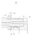
图3为本发明的电源连接器在打开状态下的剖视图。FIG. 3 is a cross-sectional view of the power connector of the present invention in an open state.
图4为本发明的电源连接器在关闭状态下的剖视图。FIG. 4 is a cross-sectional view of the power connector of the present invention in a closed state.
具体实施方式Detailed ways
图1为本发明的电源连接器100的立体分解图。本发明的电源连接器100包括插座部20、绝缘部30、手柄40、挡板50及插头部60。FIG. 1 is an exploded perspective view of a
插座部20设置在一电路板(未图标)上,并可与插头部60电性连接,以接受来自插头部60的电源,以使电路板上的电路正常运作。插座部20包括绝缘壳体22、收容空间24及导电端子26(请参照图3)。绝缘壳体22由绝缘材料制成,大致呈矩形,其包括本体224及位于本体224两侧之第一端面220和第二端面222。The
收容空间24自绝缘壳体22的第一端面220向第二端面222延伸一段距离,并通过第一端面220与外界连通。导电端子26从本体224的内壁凸出并凸露于收容空间24中。The
绝缘部30由绝缘材料制成,收容于收容空间24中。绝缘部30包括接触部36、收容部38、缺口32及第一中心通孔34,收容部38收容于收容空间24中。接触部36的外径小于收容部38的外径,第一中心通孔34贯穿接触部36和收容部38。缺口32位于收容部38的底部并靠近接触部36,且与第一中心通孔34连通。The insulating
手柄40包括多个凸起42和第二中心通孔44。所述凸起42呈对称设计,以方便用户操作手柄40。第二中心通孔44的直径略小于绝缘部30的接触部36的外径,即绝缘部30的接触部36与手柄40过盈配合,从而绝缘部30可以随手柄40一起转动。The
挡板50呈平板状,安装于手柄40和绝缘部30之间并固定于电路板上,用于限制绝缘部30的轴向移动。挡板50包括通孔52,所述通孔52的直径略大于绝缘部30的接触部36的外径。The
插头部60插入插座部20中以与插座部20电性连接,其包括端部62和插入部64。端部62由绝缘材料制成,插入部64由金属材料制成。插入部64的的外径略小于绝缘部30的第一中心通孔34的直径。The
图2为本发明的电源连接器100的立体组装图。安装时,绝缘部30的收容部38收容于插座部20的收容空间24中,且使绝缘部30的接触部36穿过挡板50的通孔52并固定于手柄40的第二中心通孔44中。插头部60的插入部64分别穿过手柄40的第二中心通孔44及挡板50的通孔52并收容于绝缘部30的第一中心通孔34中以便与插座部20电性连接,从而插座部20、绝缘部30、手柄40、挡板50及插头部60便组装为一体。FIG. 2 is a perspective assembly view of the
图3为本发明的电源连接器100的在打开状态下的剖视图。图4为本发明的电源连接器100的在关闭状态下的剖视图。使用时,如需打开电源连接器100,旋转手柄40使插座部20的导电端子26从绝缘部30的缺口32中露出,此时插头部60的插入部64便与插座部20的导电端子26电性接触,从而开启电源连接器100;如需关闭电源连接器100,旋转手柄40使绝缘部30隔绝插座部20的导电端子26和插头部60的插入部64,从而关闭电源连接器100。FIG. 3 is a cross-sectional view of the
本发明通过旋转手柄40就可以开关电源连接器100,从而不需要在电路板上设置其它的按钮来开关电源连接器100,这不仅简化了电路板的电路设计,而且节省了电路板的空间。In the present invention, the
Claims (9)
Translated fromChinesePriority Applications (2)
| Application Number | Priority Date | Filing Date | Title |
|---|---|---|---|
| CN2008103046336ACN101685929B (en) | 2008-09-24 | 2008-09-24 | power connector |
| US12/423,819US8079856B2 (en) | 2008-09-24 | 2009-04-15 | Rotatable power connector |
Applications Claiming Priority (1)
| Application Number | Priority Date | Filing Date | Title |
|---|---|---|---|
| CN2008103046336ACN101685929B (en) | 2008-09-24 | 2008-09-24 | power connector |
Publications (2)
| Publication Number | Publication Date |
|---|---|
| CN101685929A CN101685929A (en) | 2010-03-31 |
| CN101685929Btrue CN101685929B (en) | 2011-08-24 |
Family
ID=42038117
Family Applications (1)
| Application Number | Title | Priority Date | Filing Date |
|---|---|---|---|
| CN2008103046336AExpired - Fee RelatedCN101685929B (en) | 2008-09-24 | 2008-09-24 | power connector |
Country Status (2)
| Country | Link |
|---|---|
| US (1) | US8079856B2 (en) |
| CN (1) | CN101685929B (en) |
Families Citing this family (2)
| Publication number | Priority date | Publication date | Assignee | Title |
|---|---|---|---|---|
| CN105337119B (en)* | 2014-06-05 | 2017-12-26 | 鸿富锦精密工业(深圳)有限公司 | Power connector |
| US9444173B1 (en)* | 2015-06-04 | 2016-09-13 | Ford Global Technologies, Llc | Retractile socket adapter for 12V outlet |
Citations (3)
| Publication number | Priority date | Publication date | Assignee | Title |
|---|---|---|---|---|
| CN2519917Y (en)* | 2001-11-26 | 2002-11-06 | 富士康(昆山)电脑接插件有限公司 | Optical fibre connector |
| US6533610B1 (en)* | 2001-12-24 | 2003-03-18 | Hon Hai Precision Ind. Co., Ltd. | Low-profile RF connector assembly |
| CN2819523Y (en)* | 2005-05-20 | 2006-09-20 | 杭州航天电子技术有限公司 | Floating-connected electric connector |
Family Cites Families (3)
| Publication number | Priority date | Publication date | Assignee | Title |
|---|---|---|---|---|
| US5909063A (en)* | 1996-12-30 | 1999-06-01 | Philips Electronics North America Corporation | Switchable or automatically terminating connecting device and combination thereof |
| JP2001238092A (en)* | 2000-02-21 | 2001-08-31 | Maspro Denkoh Corp | Serial unit for co-viewing television |
| JP4194555B2 (en)* | 2004-04-28 | 2008-12-10 | ヒロセ電機株式会社 | Coaxial connector |
- 2008
- 2008-09-24CNCN2008103046336Apatent/CN101685929B/ennot_activeExpired - Fee Related
- 2009
- 2009-04-15USUS12/423,819patent/US8079856B2/enactiveActive
Patent Citations (3)
| Publication number | Priority date | Publication date | Assignee | Title |
|---|---|---|---|---|
| CN2519917Y (en)* | 2001-11-26 | 2002-11-06 | 富士康(昆山)电脑接插件有限公司 | Optical fibre connector |
| US6533610B1 (en)* | 2001-12-24 | 2003-03-18 | Hon Hai Precision Ind. Co., Ltd. | Low-profile RF connector assembly |
| CN2819523Y (en)* | 2005-05-20 | 2006-09-20 | 杭州航天电子技术有限公司 | Floating-connected electric connector |
Also Published As
| Publication number | Publication date |
|---|---|
| US8079856B2 (en) | 2011-12-20 |
| US20100075518A1 (en) | 2010-03-25 |
| CN101685929A (en) | 2010-03-31 |
Similar Documents
| Publication | Publication Date | Title |
|---|---|---|
| EP1427037B1 (en) | Power supply unit for electronic devices | |
| KR102084834B1 (en) | Battery pack and electric device | |
| TWI523351B (en) | Receptacle connector | |
| WO2020238813A1 (en) | Wireless earphone assembly | |
| US20160134071A1 (en) | Electrical connector with rotatable prongs | |
| CN101685929B (en) | power connector | |
| JP6499762B2 (en) | Button structure and terminal comprising the same | |
| US20110026200A1 (en) | Battery ejector and electronic device using the same | |
| GB2394125A (en) | Electrical power jack | |
| JP4833036B2 (en) | Jack | |
| CN107517555B (en) | Shell and mobile terminal | |
| TWM584993U (en) | First connector and electrical connector assembly | |
| CN215498311U (en) | Portable power source and subassembly that charges | |
| CN106617570B (en) | A kind of transit switch and the luggage for having transit switch | |
| CN203607579U (en) | Docking connectors for magnetically-attached electrical connection devices | |
| CN202134932U (en) | Mobile phone holder component | |
| CN105337119B (en) | Power connector | |
| CN219761686U (en) | Electrical component assembly module and charging equipment | |
| TWM478261U (en) | Board connecting type connector | |
| TW201014082A (en) | Power connector | |
| WO2016088642A1 (en) | Electronic key | |
| TWM454016U (en) | Power and audio connector | |
| CN201029156Y (en) | electrical connector | |
| CN109390825B (en) | Adapter and method of use | |
| TWI415338B (en) | Battery connector and electronic device using the same |
Legal Events
| Date | Code | Title | Description |
|---|---|---|---|
| C06 | Publication | ||
| PB01 | Publication | ||
| C10 | Entry into substantive examination | ||
| SE01 | Entry into force of request for substantive examination | ||
| C14 | Grant of patent or utility model | ||
| GR01 | Patent grant | ||
| CP03 | Change of name, title or address | ||
| CP03 | Change of name, title or address | Address after:No. 2, East Ring 2nd Road, Longhua Street, Longhua District, Shenzhen City, Guangdong Province Patentee after:Foxconn Technology Group Co.,Ltd. Patentee after:HON HAI PRECISION INDUSTRY Co.,Ltd. Address before:518109, No. two, No. tenth, East Ring Road, Pinus tabulaeformis Industrial Zone, Longhua Town, Baoan District, Guangdong, Shenzhen, 2 Patentee before:HONG FU JIN PRECISION INDUSTRY (SHENZHEN) Co.,Ltd. Patentee before:HON HAI PRECISION INDUSTRY Co.,Ltd. | |
| TR01 | Transfer of patent right | ||
| TR01 | Transfer of patent right | Effective date of registration:20230802 Address after:03-05, Gemdale building, 54 Jen Ding lane, Singapore Patentee after:Singapore Shanghong Yunke Co.,Ltd. Address before:518109 No. 2, East Ring 2nd Road, Longhua Street, Longhua District, Shenzhen City, Guangdong Province Patentee before:Foxconn Technology Group Co.,Ltd. Patentee before:HON HAI PRECISION INDUSTRY Co.,Ltd. | |
| CF01 | Termination of patent right due to non-payment of annual fee | ||
| CF01 | Termination of patent right due to non-payment of annual fee | Granted publication date:20110824 |