CN101684901B - Inductively powered apparatus - Google Patents
Inductively powered apparatusDownload PDFInfo
- Publication number
- CN101684901B CN101684901BCN2009101328332ACN200910132833ACN101684901BCN 101684901 BCN101684901 BCN 101684901BCN 2009101328332 ACN2009101328332 ACN 2009101328332ACN 200910132833 ACN200910132833 ACN 200910132833ACN 101684901 BCN101684901 BCN 101684901B
- Authority
- CN
- China
- Prior art keywords
- lamp
- pedestal
- sleeve
- lamp assembly
- secondary coil
- Prior art date
- Legal status (The legal status is an assumption and is not a legal conclusion. Google has not performed a legal analysis and makes no representation as to the accuracy of the status listed.)
- Expired - Lifetime
Links
- 239000003990capacitorSubstances0.000claimsabstractdescription43
- NJPPVKZQTLUDBO-UHFFFAOYSA-NnovaluronChemical compoundC1=C(Cl)C(OC(F)(F)C(OC(F)(F)F)F)=CC=C1NC(=O)NC(=O)C1=C(F)C=CC=C1FNJPPVKZQTLUDBO-UHFFFAOYSA-N0.000claimsdescription69
- 230000006698inductionEffects0.000claimsdescription24
- 238000007789sealingMethods0.000claimsdescription10
- 230000001939inductive effectEffects0.000claimsdescription7
- 230000005672electromagnetic fieldEffects0.000claimsdescription5
- 230000004044responseEffects0.000claimsdescription2
- 239000007858starting materialSubstances0.000abstractdescription10
- 230000007246mechanismEffects0.000abstractdescription6
- 230000008878couplingEffects0.000description14
- 238000010168coupling processMethods0.000description14
- 238000005859coupling reactionMethods0.000description14
- 239000010453quartzSubstances0.000description12
- VYPSYNLAJGMNEJ-UHFFFAOYSA-Nsilicon dioxideInorganic materialsO=[Si]=OVYPSYNLAJGMNEJ-UHFFFAOYSA-N0.000description12
- 239000011521glassSubstances0.000description10
- 239000004020conductorSubstances0.000description8
- 229910052736halogenInorganic materials0.000description7
- 150000002367halogensChemical class0.000description7
- 239000004809TeflonSubstances0.000description6
- 229920006362Teflon®Polymers0.000description6
- 238000013461designMethods0.000description6
- 239000007789gasSubstances0.000description6
- 238000009434installationMethods0.000description6
- 239000000463materialSubstances0.000description6
- 238000000034methodMethods0.000description5
- 235000014676Phragmites communisNutrition0.000description4
- 230000008859changeEffects0.000description4
- 230000000694effectsEffects0.000description4
- 239000012530fluidSubstances0.000description4
- 238000005286illuminationMethods0.000description4
- 239000004033plasticSubstances0.000description4
- 229920003023plasticPolymers0.000description4
- 239000011257shell materialSubstances0.000description4
- 230000004913activationEffects0.000description3
- 230000008901benefitEffects0.000description3
- 230000006378damageEffects0.000description3
- 230000007613environmental effectEffects0.000description3
- 238000009413insulationMethods0.000description3
- 238000000926separation methodMethods0.000description3
- RVCKCEDKBVEEHL-UHFFFAOYSA-N2,3,4,5,6-pentachlorobenzyl alcoholChemical compoundOCC1=C(Cl)C(Cl)=C(Cl)C(Cl)=C1ClRVCKCEDKBVEEHL-UHFFFAOYSA-N0.000description2
- XKRFYHLGVUSROY-UHFFFAOYSA-NArgonChemical compound[Ar]XKRFYHLGVUSROY-UHFFFAOYSA-N0.000description2
- XAGFODPZIPBFFR-UHFFFAOYSA-NaluminiumChemical compound[Al]XAGFODPZIPBFFR-UHFFFAOYSA-N0.000description2
- 229910052782aluminiumInorganic materials0.000description2
- 238000004458analytical methodMethods0.000description2
- 230000005540biological transmissionEffects0.000description2
- 238000002788crimpingMethods0.000description2
- 238000013016dampingMethods0.000description2
- 230000005611electricityEffects0.000description2
- QSHDDOUJBYECFT-UHFFFAOYSA-NmercuryChemical compound[Hg]QSHDDOUJBYECFT-UHFFFAOYSA-N0.000description2
- 229910052753mercuryInorganic materials0.000description2
- 238000002360preparation methodMethods0.000description2
- 238000012797qualificationMethods0.000description2
- 238000012360testing methodMethods0.000description2
- 238000009827uniform distributionMethods0.000description2
- XLYOFNOQVPJJNP-UHFFFAOYSA-NwaterSubstancesOXLYOFNOQVPJJNP-UHFFFAOYSA-N0.000description2
- 238000004804windingMethods0.000description2
- 206010009696ClumsinessDiseases0.000description1
- 238000010521absorption reactionMethods0.000description1
- 239000004411aluminiumSubstances0.000description1
- 239000005030aluminium foilSubstances0.000description1
- 229910052786argonInorganic materials0.000description1
- 230000000712assemblyEffects0.000description1
- 238000000429assemblyMethods0.000description1
- 238000003339best practiceMethods0.000description1
- 230000015572biosynthetic processEffects0.000description1
- 239000011469building brickSubstances0.000description1
- 239000000919ceramicSubstances0.000description1
- 238000007600chargingMethods0.000description1
- 230000000295complement effectEffects0.000description1
- 238000010276constructionMethods0.000description1
- 238000012937correctionMethods0.000description1
- 230000007797corrosionEffects0.000description1
- 238000005260corrosionMethods0.000description1
- 238000000354decomposition reactionMethods0.000description1
- 238000005265energy consumptionMethods0.000description1
- 238000005516engineering processMethods0.000description1
- 230000020169heat generationEffects0.000description1
- 238000010438heat treatmentMethods0.000description1
- 230000006872improvementEffects0.000description1
- 238000002955isolationMethods0.000description1
- 230000002045lasting effectEffects0.000description1
- 238000012423maintenanceMethods0.000description1
- 238000004519manufacturing processMethods0.000description1
- 229910052754neonInorganic materials0.000description1
- GKAOGPIIYCISHV-UHFFFAOYSA-Nneon atomChemical compound[Ne]GKAOGPIIYCISHV-UHFFFAOYSA-N0.000description1
- 230000008569processEffects0.000description1
- 230000035939shockEffects0.000description1
- 238000001228spectrumMethods0.000description1
- 238000002834transmittanceMethods0.000description1
Images


Classifications
- H—ELECTRICITY
- H05—ELECTRIC TECHNIQUES NOT OTHERWISE PROVIDED FOR
- H05B—ELECTRIC HEATING; ELECTRIC LIGHT SOURCES NOT OTHERWISE PROVIDED FOR; CIRCUIT ARRANGEMENTS FOR ELECTRIC LIGHT SOURCES, IN GENERAL
- H05B41/00—Circuit arrangements or apparatus for igniting or operating discharge lamps
- H05B41/14—Circuit arrangements
- H05B41/16—Circuit arrangements in which the lamp is fed by DC or by low-frequency AC, e.g. by 50 cycles/sec AC, or with network frequencies
- H—ELECTRICITY
- H05—ELECTRIC TECHNIQUES NOT OTHERWISE PROVIDED FOR
- H05B—ELECTRIC HEATING; ELECTRIC LIGHT SOURCES NOT OTHERWISE PROVIDED FOR; CIRCUIT ARRANGEMENTS FOR ELECTRIC LIGHT SOURCES, IN GENERAL
- H05B41/00—Circuit arrangements or apparatus for igniting or operating discharge lamps
- H05B41/14—Circuit arrangements
- H05B41/26—Circuit arrangements in which the lamp is fed by power derived from DC by means of a converter, e.g. by high-voltage DC
- H05B41/28—Circuit arrangements in which the lamp is fed by power derived from DC by means of a converter, e.g. by high-voltage DC using static converters
- H05B41/295—Circuit arrangements in which the lamp is fed by power derived from DC by means of a converter, e.g. by high-voltage DC using static converters with semiconductor devices and specially adapted for lamps with preheating electrodes, e.g. for fluorescent lamps
- A—HUMAN NECESSITIES
- A61—MEDICAL OR VETERINARY SCIENCE; HYGIENE
- A61L—METHODS OR APPARATUS FOR STERILISING MATERIALS OR OBJECTS IN GENERAL; DISINFECTION, STERILISATION OR DEODORISATION OF AIR; CHEMICAL ASPECTS OF BANDAGES, DRESSINGS, ABSORBENT PADS OR SURGICAL ARTICLES; MATERIALS FOR BANDAGES, DRESSINGS, ABSORBENT PADS OR SURGICAL ARTICLES
- A61L2/00—Methods or apparatus for disinfecting or sterilising materials or objects other than foodstuffs or contact lenses; Accessories therefor
- A61L2/02—Methods or apparatus for disinfecting or sterilising materials or objects other than foodstuffs or contact lenses; Accessories therefor using physical phenomena
- A61L2/08—Radiation
- A61L2/10—Ultraviolet radiation
- C—CHEMISTRY; METALLURGY
- C02—TREATMENT OF WATER, WASTE WATER, SEWAGE, OR SLUDGE
- C02F—TREATMENT OF WATER, WASTE WATER, SEWAGE, OR SLUDGE
- C02F1/00—Treatment of water, waste water, or sewage
- C02F1/30—Treatment of water, waste water, or sewage by irradiation
- C02F1/32—Treatment of water, waste water, or sewage by irradiation with ultraviolet light
- C02F1/325—Irradiation devices or lamp constructions
- C—CHEMISTRY; METALLURGY
- C02—TREATMENT OF WATER, WASTE WATER, SEWAGE, OR SLUDGE
- C02F—TREATMENT OF WATER, WASTE WATER, SEWAGE, OR SLUDGE
- C02F9/00—Multistage treatment of water, waste water or sewage
- C02F9/20—Portable or detachable small-scale multistage treatment devices, e.g. point of use or laboratory water purification systems
- F—MECHANICAL ENGINEERING; LIGHTING; HEATING; WEAPONS; BLASTING
- F21—LIGHTING
- F21V—FUNCTIONAL FEATURES OR DETAILS OF LIGHTING DEVICES OR SYSTEMS THEREOF; STRUCTURAL COMBINATIONS OF LIGHTING DEVICES WITH OTHER ARTICLES, NOT OTHERWISE PROVIDED FOR
- F21V23/00—Arrangement of electric circuit elements in or on lighting devices
- H—ELECTRICITY
- H01—ELECTRIC ELEMENTS
- H01F—MAGNETS; INDUCTANCES; TRANSFORMERS; SELECTION OF MATERIALS FOR THEIR MAGNETIC PROPERTIES
- H01F38/00—Adaptations of transformers or inductances for specific applications or functions
- H01F38/14—Inductive couplings
- H—ELECTRICITY
- H01—ELECTRIC ELEMENTS
- H01J—ELECTRIC DISCHARGE TUBES OR DISCHARGE LAMPS
- H01J13/00—Discharge tubes with liquid-pool cathodes, e.g. metal-vapour rectifying tubes
- H01J13/02—Details
- H01J13/46—One or more circuit elements structurally associated with the tube
- H—ELECTRICITY
- H01—ELECTRIC ELEMENTS
- H01J—ELECTRIC DISCHARGE TUBES OR DISCHARGE LAMPS
- H01J5/00—Details relating to vessels or to leading-in conductors common to two or more basic types of discharge tubes or lamps
- H01J5/50—Means forming part of the tube or lamps for the purpose of providing electrical connection to it
- H01J5/52—Means forming part of the tube or lamps for the purpose of providing electrical connection to it directly applied to or forming part of the vessel
- H—ELECTRICITY
- H01—ELECTRIC ELEMENTS
- H01J—ELECTRIC DISCHARGE TUBES OR DISCHARGE LAMPS
- H01J5/00—Details relating to vessels or to leading-in conductors common to two or more basic types of discharge tubes or lamps
- H01J5/50—Means forming part of the tube or lamps for the purpose of providing electrical connection to it
- H01J5/54—Means forming part of the tube or lamps for the purpose of providing electrical connection to it supported by a separate part, e.g. base
- H—ELECTRICITY
- H01—ELECTRIC ELEMENTS
- H01J—ELECTRIC DISCHARGE TUBES OR DISCHARGE LAMPS
- H01J61/00—Gas-discharge or vapour-discharge lamps
- H01J61/02—Details
- H01J61/56—One or more circuit elements structurally associated with the lamp
- H—ELECTRICITY
- H01—ELECTRIC ELEMENTS
- H01K—ELECTRIC INCANDESCENT LAMPS
- H01K1/00—Details
- H01K1/42—Means forming part of the lamp for the purpose of providing electrical connection, or support for, the lamp
- H01K1/44—Means forming part of the lamp for the purpose of providing electrical connection, or support for, the lamp directly applied to, or forming part of, the vessel
- H—ELECTRICITY
- H01—ELECTRIC ELEMENTS
- H01K—ELECTRIC INCANDESCENT LAMPS
- H01K1/00—Details
- H01K1/42—Means forming part of the lamp for the purpose of providing electrical connection, or support for, the lamp
- H01K1/46—Means forming part of the lamp for the purpose of providing electrical connection, or support for, the lamp supported by a separate part, e.g. base, cap
- H—ELECTRICITY
- H05—ELECTRIC TECHNIQUES NOT OTHERWISE PROVIDED FOR
- H05B—ELECTRIC HEATING; ELECTRIC LIGHT SOURCES NOT OTHERWISE PROVIDED FOR; CIRCUIT ARRANGEMENTS FOR ELECTRIC LIGHT SOURCES, IN GENERAL
- H05B39/00—Circuit arrangements or apparatus for operating incandescent light sources
- H—ELECTRICITY
- H05—ELECTRIC TECHNIQUES NOT OTHERWISE PROVIDED FOR
- H05B—ELECTRIC HEATING; ELECTRIC LIGHT SOURCES NOT OTHERWISE PROVIDED FOR; CIRCUIT ARRANGEMENTS FOR ELECTRIC LIGHT SOURCES, IN GENERAL
- H05B41/00—Circuit arrangements or apparatus for igniting or operating discharge lamps
- H05B41/02—Details
- H05B41/04—Starting switches
- H05B41/10—Starting switches magnetic only
- H—ELECTRICITY
- H05—ELECTRIC TECHNIQUES NOT OTHERWISE PROVIDED FOR
- H05B—ELECTRIC HEATING; ELECTRIC LIGHT SOURCES NOT OTHERWISE PROVIDED FOR; CIRCUIT ARRANGEMENTS FOR ELECTRIC LIGHT SOURCES, IN GENERAL
- H05B41/00—Circuit arrangements or apparatus for igniting or operating discharge lamps
- H05B41/14—Circuit arrangements
- H05B41/24—Circuit arrangements in which the lamp is fed by high frequency AC, or with separate oscillator frequency
- H—ELECTRICITY
- H05—ELECTRIC TECHNIQUES NOT OTHERWISE PROVIDED FOR
- H05B—ELECTRIC HEATING; ELECTRIC LIGHT SOURCES NOT OTHERWISE PROVIDED FOR; CIRCUIT ARRANGEMENTS FOR ELECTRIC LIGHT SOURCES, IN GENERAL
- H05B41/00—Circuit arrangements or apparatus for igniting or operating discharge lamps
- H05B41/14—Circuit arrangements
- H05B41/36—Controlling
- H—ELECTRICITY
- H05—ELECTRIC TECHNIQUES NOT OTHERWISE PROVIDED FOR
- H05B—ELECTRIC HEATING; ELECTRIC LIGHT SOURCES NOT OTHERWISE PROVIDED FOR; CIRCUIT ARRANGEMENTS FOR ELECTRIC LIGHT SOURCES, IN GENERAL
- H05B47/00—Circuit arrangements for operating light sources in general, i.e. where the type of light source is not relevant
- H05B47/20—Responsive to malfunctions or to light source life; for protection
- H05B47/25—Circuit arrangements for protecting against overcurrent
- B—PERFORMING OPERATIONS; TRANSPORTING
- B01—PHYSICAL OR CHEMICAL PROCESSES OR APPARATUS IN GENERAL
- B01D—SEPARATION
- B01D2201/00—Details relating to filtering apparatus
- B01D2201/30—Filter housing constructions
- B01D2201/301—Details of removable closures, lids, caps, filter heads
- B—PERFORMING OPERATIONS; TRANSPORTING
- B01—PHYSICAL OR CHEMICAL PROCESSES OR APPARATUS IN GENERAL
- B01D—SEPARATION
- B01D2201/00—Details relating to filtering apparatus
- B01D2201/34—Seals or gaskets for filtering elements
- C—CHEMISTRY; METALLURGY
- C02—TREATMENT OF WATER, WASTE WATER, SEWAGE, OR SLUDGE
- C02F—TREATMENT OF WATER, WASTE WATER, SEWAGE, OR SLUDGE
- C02F1/00—Treatment of water, waste water, or sewage
- C02F1/28—Treatment of water, waste water, or sewage by sorption
- C02F1/283—Treatment of water, waste water, or sewage by sorption using coal, charred products, or inorganic mixtures containing them
- C—CHEMISTRY; METALLURGY
- C02—TREATMENT OF WATER, WASTE WATER, SEWAGE, OR SLUDGE
- C02F—TREATMENT OF WATER, WASTE WATER, SEWAGE, OR SLUDGE
- C02F1/00—Treatment of water, waste water, or sewage
- C02F1/30—Treatment of water, waste water, or sewage by irradiation
- C02F1/32—Treatment of water, waste water, or sewage by irradiation with ultraviolet light
- C—CHEMISTRY; METALLURGY
- C02—TREATMENT OF WATER, WASTE WATER, SEWAGE, OR SLUDGE
- C02F—TREATMENT OF WATER, WASTE WATER, SEWAGE, OR SLUDGE
- C02F2201/00—Apparatus for treatment of water, waste water or sewage
- C02F2201/002—Construction details of the apparatus
- C02F2201/006—Cartridges
- C—CHEMISTRY; METALLURGY
- C02—TREATMENT OF WATER, WASTE WATER, SEWAGE, OR SLUDGE
- C02F—TREATMENT OF WATER, WASTE WATER, SEWAGE, OR SLUDGE
- C02F2201/00—Apparatus for treatment of water, waste water or sewage
- C02F2201/32—Details relating to UV-irradiation devices
- C02F2201/322—Lamp arrangement
- C02F2201/3222—Units using UV-light emitting diodes [LED]
- C—CHEMISTRY; METALLURGY
- C02—TREATMENT OF WATER, WASTE WATER, SEWAGE, OR SLUDGE
- C02F—TREATMENT OF WATER, WASTE WATER, SEWAGE, OR SLUDGE
- C02F2201/00—Apparatus for treatment of water, waste water or sewage
- C02F2201/32—Details relating to UV-irradiation devices
- C02F2201/322—Lamp arrangement
- C02F2201/3228—Units having reflectors, e.g. coatings, baffles, plates, mirrors
- C—CHEMISTRY; METALLURGY
- C02—TREATMENT OF WATER, WASTE WATER, SEWAGE, OR SLUDGE
- C02F—TREATMENT OF WATER, WASTE WATER, SEWAGE, OR SLUDGE
- C02F2201/00—Apparatus for treatment of water, waste water or sewage
- C02F2201/32—Details relating to UV-irradiation devices
- C02F2201/326—Lamp control systems
- F—MECHANICAL ENGINEERING; LIGHTING; HEATING; WEAPONS; BLASTING
- F21—LIGHTING
- F21W—INDEXING SCHEME ASSOCIATED WITH SUBCLASSES F21K, F21L, F21S and F21V, RELATING TO USES OR APPLICATIONS OF LIGHTING DEVICES OR SYSTEMS
- F21W2131/00—Use or application of lighting devices or systems not provided for in codes F21W2102/00-F21W2121/00
- F21W2131/10—Outdoor lighting
- F21W2131/103—Outdoor lighting of streets or roads
- Y—GENERAL TAGGING OF NEW TECHNOLOGICAL DEVELOPMENTS; GENERAL TAGGING OF CROSS-SECTIONAL TECHNOLOGIES SPANNING OVER SEVERAL SECTIONS OF THE IPC; TECHNICAL SUBJECTS COVERED BY FORMER USPC CROSS-REFERENCE ART COLLECTIONS [XRACs] AND DIGESTS
- Y02—TECHNOLOGIES OR APPLICATIONS FOR MITIGATION OR ADAPTATION AGAINST CLIMATE CHANGE
- Y02B—CLIMATE CHANGE MITIGATION TECHNOLOGIES RELATED TO BUILDINGS, e.g. HOUSING, HOUSE APPLIANCES OR RELATED END-USER APPLICATIONS
- Y02B20/00—Energy efficient lighting technologies, e.g. halogen lamps or gas discharge lamps
Landscapes
- Engineering & Computer Science (AREA)
- Health & Medical Sciences (AREA)
- Life Sciences & Earth Sciences (AREA)
- Power Engineering (AREA)
- Hydrology & Water Resources (AREA)
- Environmental & Geological Engineering (AREA)
- Water Supply & Treatment (AREA)
- Chemical & Material Sciences (AREA)
- Organic Chemistry (AREA)
- Public Health (AREA)
- Animal Behavior & Ethology (AREA)
- General Health & Medical Sciences (AREA)
- Epidemiology (AREA)
- Veterinary Medicine (AREA)
- Toxicology (AREA)
- Clinical Laboratory Science (AREA)
- General Engineering & Computer Science (AREA)
- Discharge Lamps And Accessories Thereof (AREA)
- Circuit Arrangements For Discharge Lamps (AREA)
- Arrangement Of Elements, Cooling, Sealing, Or The Like Of Lighting Devices (AREA)
- Circuit Arrangement For Electric Light Sources In General (AREA)
- Fastening Of Light Sources Or Lamp Holders (AREA)
- Connecting Device With Holders (AREA)
- Non-Portable Lighting Devices Or Systems Thereof (AREA)
- Led Devices (AREA)
Abstract
Description
The present invention is to be on June 7th, 2002 original application day, and international application no is PCT/US02/17901, and application number is 02829228.6 denomination of invention dividing an application for " inductively powered apparatus ".
The present invention submitted on June 12nd, 2000, and application number is No.90/592, and 194, title is the part continuation application of the U.S. Patent application of " fluid handling system (Fluid Treatment System) ".
Technical field
The present invention relates to lighting apparatus, more specifically relate to the lamp assembly relevant with the induction power illumination application.
Background technology
Although be not to use very extensively, induction coupled illumination system is known.Traditional induction coupled illumination system generally comprises the primary circuit that has by the primary coil (or " primary winding ") of power drives, and has the secondary circuit that induction receives the secondary coil (or " secondary coil ") of primary coil power.The induction coupling has multiple advantage with respect to traditional direct electrical connection.At first, the more hard-wired lamp of induction coupling lamp more safety be connected and break off with easy.Generally essential operation electric connector when directly being connected electrically in installation and removing the lamp assembly.This general relatively more bothersome danger that also can cause electric shock.General, electric connector needs part exposure at least, has therefore increased the danger of electric shock.On the other hand, for of the operation of induction coupling lamp without any need for electric connector.In fact, the secondary coil of lamp assembly is simple only need be placed near the power is offered the lamp assembly of primary coil.Second has eliminated the problem of following conventional electric connector through saving electric connector, is easy to corrosion and wearing and tearing such as the electric connector of routine, thereby has improved the reliability of system.When environmental condition made electric connector be in wet condition, these problems were more responsive to outdoor installation.When reusing, mechanical connecting device also is easy to wearing and tearing and ultimate failure.The 3rd, what induction coupling lamp was intrinsic can reduce the electricity harm on the lamp assembly.As mentioned above, lamp assembly and power supply are electric insulations.All electric power must be sent to the lamp assembly from power supply through induction.Because the inherence that exists responding to the power that is sent to the lamp assembly limits, the power in the lamp assembly is restricted, and the risk of electricity harm has been lowered.
Although induction coupling lamp provides the multiple significant advantage that is superior to directly connecting lamp, they exist great shortcoming.Induction coupling is intrinsic more directly is electrically connected poor efficiency.This part is owing to needing electric energy to produce and keeping electromagnetic field.The poor efficiency of conventional induction coupling mainly is that the tuning circuit by clumsiness causes.These poor efficiency are proved by the noise of the generation of the vibrations in primary coil and the secondary coil and the increase of heat absorption.This efficiency becomes serious in high power lamp is used.And existing circuit for lamp needs accurately to locate primary coil and secondary coil so that rational level of efficiency to be provided.This needs more accurate tolerance, and the design and the structure of restriction lamp assembly and whole lamp.
One of integrity problem of the maximum that light trade faces runs through the lamp sleeve by electric wire or other conductors and causes.Typically, electric wire pierces into the inside of lamp through glass header.Because glass is not easy to adhere to and sealed guide, leak the position that therefore exists the risk on the material can cause passing lamp at electric wire.Although made great efforts to optimize sealing, but still had great integrity problem.
For conventional induction power lamp, also exist to be accompanied by the circuit for lamp component exposure in environment and the integrity problem that produces, such as, may damage component from water in the environment or moisture.In order to address this problem, at least one induction power illuminator is enclosed in whole lamp assembly in the sleeve of sealing.The U.S. Pat of Hutchisson etc. has disclosed a kind of lamp for 5,264,997 kinds, and this lamp is installed on the printed circuit board (PCB), with a plurality of binding posts in secondary coil interval.Printed circuit board (PCB) comprises the required electronic component of various induction coupling operations.Separating shell and lens component seals each other and forms and do not leak shell around lamp, printed circuit board (PCB) and secondary coil.Shell is concrete is set to be fit to the shape accepting secondary coil and install each other with the lamp socket that holds primary coil.Although can provides improved protection to environmental condition, volume is big comparatively speaking for it, and the light according to the transmission of lens direction only is provided.
This shows, still need a kind of efficient high, have an improved reliability and be fit to the induction coupling lamp assembly of multiple different modulated structures easily under various conditions.
Summary of the invention
The problems referred to above are able to solve through the present invention, wherein be provided with lamp in the lamp assembly, the inductive secondary and the capacitor of electric power are provided for lamp.Capacitor is connected with lamp and secondary coil, and its reactance under operating frequency approximates or be slightly less than lamp and the resultant impedance of secondary coil under operating temperature.As a result, circuit for lamp is at resonance or near work under the condition of resonance.For discharge lamp, series capacitors also plays the effect of the electric current in the restriction secondary circuit, gets rid of the uncontrolled increase of electric current, not so for discharge lamp the problems referred to above can take place.
On the other hand, the present invention provides a kind of inductively powered apparatus, and wherein whole lamp assembly circuit is sealed in the transparent sleeve.Preferably, whole lamp assembly circuit comprises secondary coil and any relevant capacitor, is sealed in the sleeve of lamp.In optional embodiment, secondary coil and lamp, and any capacitor and starting drive be accommodated in plastics, Teflon, glass or the quartz sleeve of second sealing, and do not have electric wire or miscellaneous part to pass this sleeve.Preferably find time or fill function gas so that the heat conduction or the heat insulation of desired level to be provided in space between second sleeve and said lamp sleeve.
On the other hand, the present invention provides the remote activation switch so that preheating discharge lamp to be provided.In the special time period of lamp between the starting period, switch makes the electric pole short circuit on secondary coil.In addition, this circuit resistor that can also have a series connection preheats electric current with restriction.In one embodiment, switch is the preferred electromagnetic switch that is started by the electromagnetic field of the corresponding coil generation in lamp control circuit.
The present invention provides a kind of lamp assembly that is used for the cheap and simple of induction power illumination.Because therefore the lamp assembly has high power factor and high efficient at resonance or near carrying out work under the condition of resonance.Reduced energy consumption through heat generation, even and under high-power relatively application, the quiet of induction coupling also is provided.The efficient of secondary coil does not need primary coil to aim at the accurate of secondary coil, therefore allows lamp and lamp assembly on layout and structure, to have the bigger free degree.Seal sleeve provides has improved circuit for lamp to environmental protection, and does not limit the transmission of light from lamp.Although have many light sources, the spectrum that sends is perhaps lossy based on the specific transmittance of shell material, such as, some material is not high radioparent to ultraviolet light.The present invention allows functional gas to be trapped in the sleeve of sealing, to increase or to reduce the degree of isolation of lamp and environment.In addition, through whole circuit for lamp is enclosed in the lamp sleeve, can save the electric wire that passes sleeve or the needs of electric lead.This has improved the reliability of lamp to a great extent when significantly reducing production loss.Simultaneously, electromagnetic switch of the present invention provides a kind of cheapness and reliable alternative of conventional start-up circuit.
Below, in conjunction with accompanying drawing the present invention being elaborated, these and other purpose of the present invention, advantage and characteristic become more obvious.
Description of drawings
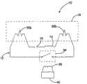
Fig. 1 is the sectional view of lamp assembly according to an embodiment of the invention;
Fig. 2 is the sectional view perpendicular to the lamp assembly shown in Figure 1 of sectional view shown in Figure 1;
Fig. 3 is the sketch map of circuit for lamp according to an embodiment of the invention;
Fig. 4 is the sectional view with another kind of optional lamp assembly of incandescent lamp;
Fig. 5 is the sectional view that has with the another kind of optional lamp assembly of the incandescent lamp of general pedestal;
Fig. 6 is the sectional view with another kind of optional lamp assembly of Halogen lamp LED;
Fig. 7 is the sectional view with another kind of optional lamp assembly of the Halogen lamp LED that is provided with pedestal in the lamp sleeve outside;
Fig. 8 has the not sectional view of the another kind of optional lamp assembly of the Halogen lamp LED of tape base seat;
Fig. 9 is the sectional view with another kind of optional lamp assembly of the fluorescent lamp of not being with outer sleeve;
Figure 10 is the sectional view with another kind of optional lamp assembly of T-5 or T-8 type fluorescent lamp;
Figure 11 is the sketch map that is used in the circuit for lamp in the lamp assembly shown in Figure 10;
Figure 12 is the sketch map that is used in the another kind of optional circuit for lamp in the lamp assembly shown in Figure 10;
Figure 13 is the sketch map that is used in another the optional circuit for lamp in the lamp assembly shown in Figure 10;
Figure 14 is the sketch map that is used in the other a kind of optional circuit for lamp in the lamp assembly shown in Figure 10;
Figure 15 is the sectional view with another kind of optional lamp assembly of PL type fluorescent lamp;
Figure 16 has the sectional view of the another kind of optional lamp assembly of PL type fluorescent lamp perpendicular to cross section shown in Figure 15;
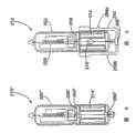
Figure 17 is partial cross section's exploded view of another kind of optional lamp assembly;
Figure 18 is the sectional view of the part of the optional lamp assembly of another kind shown in Figure 16;
Figure 19 is the sectional view of the part of another kind of optional lamp assembly; And
Figure 20 is the sectional view of the part of another optional lamp assembly.
The specific embodiment
The lamp assembly is as illustrated in fig. 1 and 2 according to an embodiment of the invention, and generally is marked as 10.For disclosed purpose, the present invention at first combines to be retrofitted in 11 watts of ultraviolet rays of conventional PL-S type (ultraviolet ray) lamp that for example is used for water treatment facilities that uses under 38 watts of conditions and describes.Lamp assembly 10 generally includes circuit forlamp 12 and outer sleeve 70.Circuit forlamp 12 comprisessecondary coil 14,capacitor 16 andlamp 18, all series connection (referring to Fig. 3).Secondary coil 14 inductions receive the power from the primary coil (not shown) of associated ballast (not shown).Series capacitor 16 is specific tuning through what will be described in detail later, so that circuit for lamp resonant operation under the specific operation condition.Whole circuit forlamp 12 is completely enclosed within theouter sleeve 70, comprisessecondary coil 14,capacitor 16 and lamp 18.At least a portionouter sleeve 70 is transparent, and does not have electric wire or other elements to pass.
Although in conjunction with 38 watts of ultraviolet lamps of PL-S type following embodiment is described, the present invention is intended to or is suitable for use in the lamp of all kinds or pattern, comprises discharge lamp, incandescent lamp, pulse white light and light emitting diode (" LED ") lamp.The disclosure provides other alternate embodiments of multiple demonstration incandescent lamp and discharge lamp.These embodiment are not to be the qualification to the claim scope in order to explain extensive use of the present invention and applicability.
The multiple ballast that is used to start inductively powered apparatus of the present invention is known for a person skilled in the art.Therefore, no longer ballast is described in detail.The ballast that is specially adapted to the PL-S type 38W ultraviolet lamp in the illustrative example is what on June 12nd, 2000 submitted to; Application number is No.90/592194; Title is open in the U.S. Patent application of " fluid handling system (FluidTreatment System) ", and this application is quoted by integral body at this as a reference.This ballast is suitable for all embodiment disclosed by the invention valid function is provided.
I.The structure of lamp
As stated, PL-S type 38W ultraviolet lamp preferably includes and is used for sealedlight circuit 12 to protect theouter sleeve 70 of its (referring to Fig. 1 and Fig. 2) not affected by environment.Outer sleeve 70 preferably includesmain body 90 and lid 92.Main body 90 is generally the cylindrical tube with openend and blind end.It is after 90s that circuit forlamp 12 is installed into main body, andlid 92 seals with complete closed circuit forlamp 12 on the openend of main body 90.Circuit forlamp 12 generally comprisessecondary coil 14,capacitor 16 and lamp 18.Be described below, circuit forlamp 12 can also comprise starter 35 (referring to Fig. 2).Lamp 18 is general PL-S type lamp with quartz socket tube commonly used, and this quartz socket tube has twoparallel shank 72a-b that interconnect common qualification sections 28.Found time by part and contain required discharge gas inchamber 28, such asmercury vapour.Base 32a-b is arranged on the bottom of eachshank 72a-b.A pair of electrode 26a-b common or custom design is set in thechamber 28, installs one at the top of each base 32a-b.In this embodiment,outer tube 70 is preferably processed to see through ultraviolet light efficiently by quartz.In non-ultraviolet application, outer tube can be processed by glass, Teflon or plastics, depends in part on the heat of lamp generation and the working environment of lamp.For example, another kind of selectable outer tube is processed by the Teflon pipe that certain-length has sealing opposite end (not shown).The Teflon pipe can be assembled on the remainder of lamp assembly, and its opposite end can be rolled-up, perhaps seals with sealing Teflon sleeve.Preferably, each end utilization heat of Teflon pipe and pressure are to oneself turning back and curling.
In one embodiment, thespace 96 betweensleeve 70 and the lamp sleeve 52 is configured to provide the assembly of the lamp with required electric conductivity or insulating properties outside.For example,space 96 can be evacuated so that lamp and cold environment completely cut off.Another kind is selected, andspace 96 is filled heavier gas, and like argon and neon, perhaps fill fluid is with conduction warm under thermal environment.Under thermal environment, will help guard lamp unlikely overheated, and help to provide maximum intensity from lamp conduction heat.
In great majority were used,lamp assembly 10 can also comprise the mechanism that ballastsense light assembly 10 is existed.This has only whenlamp assembly 10 is installed ballast could start the primary coil (not shown).Although induction mechanism is also non-essential in many application; Particularly in low power applications; But it provides more effective design to give birth to heat with conserve energy, minimizing really, and protects primary coil to avoid certain type infringement following lasting operation to cause.In one embodiment,lamp assembly 10 comprisessensor magnet 60 and ballast (not shown), and perhaps relevant control circuit comprises the reed switch (not shown) that is started by sensor magnet 60.More specifically, whenlamp assembly 10 was mounted,sensor magnet 60 was arranged near reed switch (not shown) place.Magnetic field fromsensor magnet 60 causes reed switch 62 to be closed, and provides signal listbright lamp assembly 10 to be in suitable position to ballast or control circuit thus.Sensor magnet is preferably mounted on thepedestal 50, but also can be installed in other desired positions.The another kind of selection is thatsensor magnet 60 can be replaced by the mechanical switch (not shown) with the reed switch (not shown).Such as, switch can be set on the position of the mechanical closing through the installation of lamp assembly 10.The another kind of selection provides the on/off switch of lamp to manually boot, and for example opens and close the toggle switch of ballast selectively.
II.Circuit for lamp
To combine above-mentioned PL-S type 38W ultraviolet lamp (referring to Fig. 1 and 2) that circuit forlamp 12 is described now.As stated, circuit forlamp 12 generally includeslamp 18,secondary coil 14 and capacitor 16.The sketch map of circuit forlamp 12 is as shown in Figure 3.In this embodiment, circuit for lamp comprises singlesecondary coil 14, and the coil that preferably is made up ofsmall diameter wire 22 constitutes.The precise characteristics ofsecondary coil 14 will be as the function of primary coil (not shown) and load (like lamp) and change along with usedifferent.Lead 22 preferred magnetic wire or twisted wires (LITZ) commonly used depend on that power setting and hear rate are diffusing.Lead preferably twines around thepedestal 50 in theannular groove 80, and this makessecondary coil 14 have hollow core.If desired,hollow core 24 can be replaced by other cores commonly used.The diameter of the type of lead, the lead number of turn and core (and diameter of the conductor turns that obtains thus) will change along with use different, depend on the for example load characteristic of primary coil andlamp 18 of various factors.Select the function of the inductance ofsecondary coil 14 as operating frequency and the impedance of load (being lamp) under supply power.More specifically, the inductance ofsecondary coil 14 is confirmed by following formula:

In 38 watts embodiment,secondary coil 14 is configured to receive the power of the primary coil of working under the about 100 kilo hertzs frequency of leisure.Secondary coil 14 comprises 72 circle leads and primary coil comprises 135 circle leads.In described 38 watts of embodiment,secondary coil 14 has the inductance value of 196 microhenrys when 100 khz frequencies, have about 123 ohm reactance value.Secondary coil 14 preferably is placed in thepedestal 50 of lamp assembly 10.Select the diameter of secondary coil, it is fitted closely in the pedestal 50.Secondary coil 14 is electrically connected withlamp 18 through lead-in wire 51a-b.Although secondary coil is preferably circle, it also can change according to the difference of using.For example, secondary coil can be for square, oval, triangle, trapezoidal, hexagon, or even be sphere.Secondary coil preferably with concentric outside or the inside of being arranged on of primary coil, perhaps two coils can be provided with end-to-end.
Selectcapacitor 16, best PFC is provided, resonance is provided in circuit for lamp thus to consider mechanical constraint.The preferred .90 of power factor or bigger, and .96 or bigger more preferably, but lower in some applications value also is an acceptable.Do not have enough power factor correction, the quadrature current in the secondary coil will reflect back in the primary coil, becomes more low-impedance load.This will cause the upwards drift under operating power and current condition, and the higher consume that produces with the heat gain mode in primary circuit.This effect and initial expection are opposite, and the opposite nature of the reflected umpedance of series resonance primary circuit produces but this is really.When test had been disclosed in factor and is lower than .90, quadrature current in primary coil and loss increased very soon.This possibly have has dysgenic material to efficient, especially when these losses are affixed to the loss that is caused by coupling factor and dc impedance.Generally speaking, selectcapacitor 16, to have the reactance impedance that approximates or be slightly less thanlamp 18 its resistive impedance andsecondary coil 14 when its operating temperature.Be similar to the inductance ofsecondary coil 14, select the function of the reactance of capacitor as operating frequency under the given power and load (being lamp) impedance.More specifically, select the reactance of capacitor according to following formula:

When this reactance value,capacitor 16,secondary coil 14 andlamp 18 will provide high power factor and high efficiency is provided thus near carrying out work under the condition of resonance.In illustrative example,capacitor 16 is near 12.9 nanofarads (nf).This value will respond the variation of primary coil (not shown),secondary coil 14 and/orlamp 18 and change.
Aforesaid secondary coil and capacitor formula have provided rough required electric capacity and secondary coil reactance value roughly.In order to obtain being worth more accurately (and accurate tune power factor, current limitation effect and overall work parameter) thus, can use loop tester.Need this loop test to obtain the level of efficiency in required secondary circuit in some applications.The running parameter of these designs comprise preheat, trigger voltage and operating current.These all parameters can dispose through tuning process with ratio, electric capacity and variation inductance.
Though it is tuning thatcapacitor 16 preferably carries out according tosecondary coil 14 andlamp 18 whenlamp 18 is in operating temperature,capacitor 16 also can be tuning so that optimum efficient to be provided At All Other Times.Such as, in the discharge lamp of the big electric current of needs with the startup lamp, the present invention can be used for gain circuitry when starting.In such application, select electric capacity to have the reactance that approximates secondary coil and the combined impedance of electric light under start-up temperature (rather than operating temperature).This will increase the efficient of circuit for lamp between the starting period, allow to use to have the more peaked ballast of low current.
According to the character of plasma, discharge lamp attempts to keep the inherent voltage value place of voltage in substantial constant.As a result, whensecondary coil 14 produced the voltage of the inherent voltage that surpasses lamp, lamp was with consuming too much power.Owing to the impedance response electric current of discharge lamp reduces, so modulating voltage produces ever-increasing bigger electric current until the circuit limit or self-destruction.The problems referred to above are able to solve throughcapacitor 16, and its effect is the electric current that lamp is supplied with in restriction.Current limit function is the inherent characteristic of capacitor.Confirmed the capacitance that the capacitance that makes secondary coil be in resonance approximates can provide the suitable current restriction.Correspondingly, confirmed in the present invention through selecting capacitance to obtain current limit function so that suitable overall power factor to be provided.
When the present invention was merged in the discharge lamp assembly, circuit forlamp 12 preferably included starter commonly used 35 (referring to Fig. 2), glow bulb or other devices that are equal to mutually.Starter and glow bulb are known, therefore describe in detail no longer in this application.In an embodiment of discharge lamp assembly, starter commonly used is substituted by the remote activation switch, such as electromagnetic switch 34 (referring to Fig. 3).The access thatelectromagnetic switch 34 is connected betweenelectrode 36a-b allows the circuit betweenswitch 34 closedelectrode 36a-b thus selectively.When closing,switch 34 allows electric current directly to flow throughelectrode 36a-b, rather than through needs arc through gas.The result is that whenswitch 34 cut out,electrode 36a-b was by Fast Heating.The direction that preferably is basically perpendicular to the primary coil electromagnetic field is provided withelectromagnetic switch 34, so thatelectromagnetic switch 34 is not started by the electromagnetic field of primary coil.Replace, thecoil 38 of separation is arranged near theelectromagnetic switch 34, can be recharged with selectivity this its and close switch 34.Electromagnetic switch is controlled in the work ofmicroprocessor 40preferred control coils 38 thus.Whenmicroprocessor 40 is programmed in each circuit for lamp and is energized, in a Fixed Time Interval, givecoil 38 chargings.This closes electromagnetic switch, simultaneously short-circuiting electrode 36a-b.The another kind of selection be,microprocessor 40 can be substituted by one-shot timer circuit (not shown) commonly used, and one-shot timer is configured in order to when each lamp starts, and gives the coil charges required time.
III.Other optional embodiment
Perhaps, being configured in of lamp assembly has significant variation in the different application, depend on the type of lamp and relevant power requirement substantially.The present invention can improve with permission and in a broader category of existing illuminators, use.Following alternative has been described all-purpose plurality of optional embodiment.These alternatives are intended to explain adaptability widely of the present invention, but not are exhaustive.
Fig. 4 shows another the optional embodiment that applies the present invention in the incandescent lamp.In this embodiment,lamp assembly 110 comprisesglass sleeve 152 and plastic base 150.Glass sleeve 152 is generally bulb-shaped, and comprises and bend to the inside and be generally columniform base 132.Secondary coil 114 is installed in theglass sleeve 152 around base 132.Filament 136 is installed in the spherical part that extends upward on the secondary coil toglass sleeve 152 in a usual manner.Different with the foregoing description,pedestal 150 is assembled to the outside ofglass sleeve 152 in the present embodiment.Pedestal is configured with corresponding socket (not shown) and interfixes.Shown inpedestal 150 be generally circle and comprise and being configured in order to fit into theannular recess 156 in the corresponding socket (not shown)fast.Pedestal 150 comprises that alsoupper flange 158 is to be provided for removing from the socket (not shown) the promptly limit of lamp assembly 110.Butpedestal 150 can have multiple various structure to allow lamp assembly and various socket mechanical connection.For example, pedestal can be have externally threaded.As shown in the figure,lamp assembly 110 preferably includes sensor magnet 160.Sensor magnet 160 can be mounted on thecorresponding maintenance wall 162 onpedestal 150 bottom surfaces.As stated,sensor magnet 160 and magnetic starting switch synergy are with existing of prompting primary coil or control circuit lamp assembly 110.This only just is energized primary coil whenlamp assembly 110 is in suitable position.As shown in Figure 5, incandescent lamp assembly 110 ' can be configured to and can carry out work with the general pedestal of routine.In this embodiment, pedestal 150 ' comprises a pair ofinstallation pin 156a-b, its can with the coupling slot interlocking in the general pedestal lamp socket (not shown) of routine.
Fig. 6 shows another the optional embodiment of the present invention that is applied in the Halogen lamp LED.In this embodiment,lamp assembly 210 generally comprisesquartz sleeve 252 and base of ceramic 250.Select the material ofsleeve 252 andpedestal 250, extra high temperature when working can bear Halogen lampLED.Quartz sleeve 252 is sealing fully preferably, and does not comprise any element that runs through, like lead or otherelectric connectors.Filament 236,secondary coil 214 andcapacitor 216 are closed in the quartz sleeve 252.In some applications,capacitor 216 is optional for acceptable level of efficiency is provided, therefore corresponding can removing.Lamp assembly 210 further comprises theheat reflector 258 that is arranged betweenfilament 236 and the secondary coil 214.Pedestal 250 can comprise thescrew thread 256a-b of 1/4th circles, and it is mutual threaded engagement in corresponding socket (not shown).Pedestal 250 can have another kind of selectable structure so that be installed on thesocket.Sensor magnet 260 preferably is installed on the inner bottom surface ofpedestal 250.
In selectable Halogen lamp LED assembly 210 ', quartz sleeve 252 ' is shortened with in the neck that just ends at pedestal 250 ' (referring to Fig. 7).Secondary coil 214 ' is moved to the outside of quartz socket tube 252 ', and is arranged in thepedestal 250 '.In this embodiment, the insulation of secondary coil 214 ' and filament 236 ' heat.This embodiment can also comprise sensor magnet 260 '.
At another optional Halogenlamp LED assembly 210 " in, pedestal is removed, andsensor magnet 260 " be moved intosealing quartz sleeve 252 " inside.As shown in Figure 8,quartz sleeve 252 " define fully aroundsleeve 252 " recess 256 of the annular of extending ", so thatlamp assembly 210 " can be fitted into fast in the corresponding socket (not shown).
Another alternate embodiments is as shown in Figure 9.In this embodiment,lamp assembly 310 comprises thepedestal 350 that is arranged onlamp sleeve 352 outsides, andlamp assembly 310 does not comprise outersleeve.Lamp sleeve 352 enclosed-electrode 336a-b and required discharge gas such as mercury vapour.Secondary coil 314,capacitor 316, any required actuating mechanism (such as starter commonly used or aforesaid magnetic starting switch) and all electric connectors are accommodated in thepedestal 350, but inlamp sleeve pipe 352outsides.Pedestal 350 is configured in order to corresponding with the general pedestal of routine, and comprises a pair ofinstallation pin 356a-b, its can with the coupling slot interlocking in the lamp socket (not shown).Pedestal 350 also can be selected to be configured in order to be complementary with othersockets.Sensor magnet 360 is preferably mounted in the pedestal 350.If desired, thislamp assembly 310 also can increase the outer sleeve (not shown) to increase its protection to environment.If comprise outer tube, outer sleeve preferably extends around the overall lamp assembly except pedestal 350.Pedestal 350 be installed in outer sleeve the outside so that its can cooperatively interact with lamp socket.
Figure 10 and Figure 11 show another the optional embodiment of the present invention that is applied in T5 or the T8 type fluorescent lamp.Lamp assembly 410 comprises the glass sleeve 452 and a pair of secondary coil 414a-b of lengthening, and each is positioned at an end of sleeve 452.Because two secondary coil 414a-b are in different physical locations, power supply preferably is configured in order to comprise the primary coil (not shown) of two separation, is respectively two secondary coil 414a-b electric energy is provided.Two primary coils are arranged on contiguous corresponding secondary coil place.Typically uniform distribution electric energy between coil 414a-b still is not strict necessary.Preferred secondary coil 414a-b is set up opposite polarity, and each primary coil and secondary coil combine to be configured, in order to half voltage and the electric current that keeps needing for lamp power supply station.Sleeve 452 is preferably included in the annular base 432a-b of each opposite end formation to hold secondary coil 414a-b.Electrode 436a-b is electrically connected with each secondary coil 414a-b.Capacitor 416 is connected in series between two secondary coil 414a-b.The method for optimizing that calculates the value of the capacitor 416a-b among this embodiment is, supposes and only uses a coil, according to above-mentioned method (relevant with first embodiment that discloses) circuit carried out initial analysis.Then the single capacitance under this supposition situation is halved, as each capacitance among two electric capacity 416a-b in the present embodiment.Available end cap 420a-b, preferably made of aluminum, be assembled on the opposite end of sleeve 452.Lamp assembly 410 can comprise starter 435 commonly used, and is shown in figure 11.In this embodiment, conductor 498a-b need be provided between two secondary coil 414a-b.Conductor 498a-b preferably is contained in the lamp sleeve pipe 452.As the optional mode of another kind, magnetic switch 434a-b, perhaps other remote activation switches can substitute conventional starter.Shown in figure 12, lamp assembly 410 ' comprises the separating switch 434a-b that is installed in series between each secondary coil 414a-b ' and its corresponding filament or electrode 436a-b '.Through closing this switch 434a-b, directly offer corresponding filament from the electric energy of each secondary coil 414a-b '.In this embodiment, between secondary coil 414a-b ', has only a conductor 498 '.Capacitor 416 ' is connected in series along conductor 498 '.
Figure 13 shows and is used for twincoil lamp assembly 410 " another optional circuit.In this circuit, at twosecondary coil 414a-b " between do not need conductor.What replace is eachsecondary coil 414a-b " comprise special switch 434a-b " and dedicated capacitor 416a-b ".Lamp controller preferably is configured to be used so that two switch 434a-b " open and close simultaneously.Calculable capacitor 416a-b " the best practice of capacitance be to suppose and only use a secondary coil circuit to be carried out initial analysis according to the open method of first embodiment.The capacitance of single capacitor of this supposition configuration of halving then is with two capacitor 416a-b as present embodiment " in each capacitance.In some applications, electric energy can not uniform distribution between two secondary coils.In such embodiment, the ratio between the capacitance of two capacitors should and two secondary coils between power ratio suitable.
Figure 14 shows and is used fortwin coil lamp 410 " ' another optional circuit.In this embodiment, only be provided with asecondary coil 414 " '.Secondary coil 414 " ' with theelectrode 436a-b that is positioned at the lamp opposite end " ' be connected.This circuit is included in the pair ofconductors 498a-b that extends between coil " '.Be provided withconventional starter 435 " ' or other actuating mechanisms, such as magnetic switch, in order to start lamp.In this embodiment, preferablyselect capacitor 416 according to the method for the embodiment of first disclosure " ' capacitance.
The present invention is applied in another alternate embodiments such as the Figure 15 and shown in Figure 16 in the PL type fluorescent lamp.In this embodiment, whole circuit for lamp is closed in the lamp sleeve pipe 552, and does not comprise outer tube.As shown in the figure, lamp assembly 510 comprises the lamp sleeve pipe 552 with two interconnective shank 502a-b.This lamp assembly 510 can comprise the twin coil circuit for lamp of above-mentioned any kind of.For illustrative purposes, this embodiment combines lamp assembly 510 to describe, and this lamp assembly has the secondary coil 514a-b of the separation on the pedestal that is installed in each shank 502a-b.Two secondary coil 514a-b preferably provide electric power by a primary coil around perhaps contiguous lamp assembly 510 1 ends.Each secondary coil 514a-b connects with electrode 536a-b, capacitor 516a-b and magnetic starting switch 534a-b.As stated, select the capacitance of each capacitor 516a-b in conjunction with embodiment 13 described embodiment.This lamp assembly 510 can also comprise sensor magnet 560.
The lamp selected assembly 610 with available hermetically-sealed construction is like Figure 17 and shown in Figure 180.Shown in decomposition view 17, lamp assembly 610 generally comprises binding ring 602, outer sleeve 670, lamp 618 and pedestal 650.Binding ring 602, outer sleeve 670 and pedestal 650 fitted seal lamp assemblies 610.Shown in figure 18 will be clearer, pedestal 650 comprises in order to hold the cylindrical center part 652 of secondary coil 614 and lamp 618.More specifically, lamp 618 is installed on the printed circuit-board assembly (" PCBA ") 654, and this printed circuit-board assembly preferably supports any capacitor or the actuating mechanism in the lamp assembly 610.The sub-assembly of lamp/PCBA for example is installed on the pedestal 650 through the mode of retaining element or cooperation fast.Pedestal 650 can also comprise the ring-shaped groove 656 around pedestal 650, the end that is used to hold outer sleeve 670.An O type circle 604 is assemblied in the ring-shaped groove 656 around core 652.Pedestal 650 can comprise that the circumferential rib (not shown) is in order to prevent upward core 652 of O type circle 604 arches.In case be mounted, O type circle 604 is arranged between the external diameter of core 652 of internal diameter and pedestal 650 of outer sleeve 670.In this position, O type circle 604 not only provides effective waterproof sealing, but also can be used as the shock damping device so that damping is carried out in vibrations between lamp and the outer sleeve 670.Outer sleeve 670 is generally the cylindrical tube with blind end and openend.Openend around outer sleeve 670 is provided with crimping 672 or other flanges.Outer sleeve 670 is fixed on the pedestal 650 through locking ring 602.Locking ring 602 is generally annular and is assembled on outer sleeve 670 and the pedestal 650.Locking ring 602 has down the cross section of L shaped shape usually, and has radial legs 674 and axial shank 676.Radial legs 674 engages with crimping 672, and axially shank 676 engages with the outer surface of pedestal 650.The another kind of selection is that shown in figure 19, locking ring 602 ' also can be configured to axial shank 676 ' can be mounted in the ring-shaped groove 656 ' with pedestal 650 '.In two embodiment, axially shank 676 or 676 ' is fixed on pedestal 650 or 650 ' upward so that outer sleeve 670 is locked in the ring-shaped groove 656 of pedestal 650.Locking ring 602 can be attached on the pedestal 650 with various connected modes.For example locking ring 602 can be attached on the pedestal 650 through the mode of sound wave or thermal weld.The another kind of selection is; Lamp assembly 610 " can comprise the locking ring 602 of lower flange 678 (referring to Figure 20) "; So that locking ring 602 ' is assembled on the pedestal 650 ' fast, perhaps the screw thread (not shown) can be set on locking ring and pedestal, so that the locking ring screw thread is fixed on the pedestal.
Above-described is various embodiments of the present invention.Short of spirit and the scope that departs from the accompanying claims to be limited can be made multiple improvement and variation, and said claim makes an explanation according to the doctrine of equivalents of Patent Law.Anyly quote what the parts in the claim carried out with singulative, for example use " one ", " this " and " said ", it is single should not be construed as and limiting these parts.
Claims (9)
1. induction power discharge lamp assembly comprises:
Lamp, this light fixture have first electrode, second electrode and are contained in the discharge gas in the lamp sleeve;
Be used to receive inductive secondary from the power of inductive primary coil;
With said lamp and said secondary coil series capacitors;
Electric connector is connected to said first electrode with said secondary coil, and in the time of thus in being in the suitable electromagnetic field that is produced by the inductive primary coil, said inductive secondary provides power for said first electrode; With
Wherein said inductive secondary, said capacitor and said electric connector are closed in the said lamp sleeve, and said thus lamp is self-contained, and said lamp sleeve is sealed fully and do not run through.
2. induction power discharge lamp assembly as claimed in claim 1; Wherein said inductive secondary has reactance; Said light fixture has the impedance that equals said secondary coil reactance value basically, and said capacitor has the reactance value that equals the combined impedance of said secondary coil and said lamp when start-up temperature basically.
3. induction power discharge lamp assembly as claimed in claim 2; Further comprise magnetic starting switch; This magnetic starting switch is operated between the opening and closing position through response magnetic field; When in said closed position, said magnetic starting switch allows electric current directly to flow through electrode and do not flow through discharge gas.
4. induction power discharge lamp assembly as claimed in claim 1 comprises:
Pedestal;
Be installed in the lamp on the said pedestal;
Be installed in the outer sleeve that centers on said lamp on the pedestal, said outer sleeve has flange;
Be arranged on the flexible elastic sealing element between said pedestal and the said outer sleeve;
Be installed on the said outer sleeve and be fixed to the locking ring on the said pedestal, said locking ring is held back the residence and is stated flange said outer sleeve is remained on the said pedestal the suitable position around lamp.
5. lamp assembly as claimed in claim 4, wherein said pedestal comprises ring-shaped groove, said flange is arranged in the said ring-shaped groove.
6. lamp assembly as claimed in claim 5, wherein said seal is installed in the said ring-shaped groove around said pedestal.
7. lamp assembly as claimed in claim 6, wherein said locking ring comprises radial component and axial component, said radial component and said flange engages, said axial component is fixed on the said pedestal.
8. lamp assembly as claimed in claim 4; Wherein said pedestal comprises and has the columniform part of being substantially of outer surface; Said outer sleeve has and has the columniform part of being substantially of inner surface; Said seal is set between the said inner surface of said outer surface and said sleeve of said pedestal, and directly engages the said outer surface of said pedestal and the said inner surface of said sleeve.
9. lamp assembly as claimed in claim 8, wherein said seal are O type seal.
Applications Claiming Priority (3)
| Application Number | Priority Date | Filing Date | Title |
|---|---|---|---|
| US10/133,860 | 2002-04-26 | ||
| US10/133860 | 2002-04-26 | ||
| US10/133,860US6731071B2 (en) | 1999-06-21 | 2002-04-26 | Inductively powered lamp assembly |
Related Parent Applications (1)
| Application Number | Title | Priority Date | Filing Date |
|---|---|---|---|
| CN028292286ADivisionCN1631060B (en) | 2002-04-26 | 2002-06-07 | Induction Power Lamp Assembly |
Publications (2)
| Publication Number | Publication Date |
|---|---|
| CN101684901A CN101684901A (en) | 2010-03-31 |
| CN101684901Btrue CN101684901B (en) | 2012-09-26 |
Family
ID=29249078
Family Applications (5)
| Application Number | Title | Priority Date | Filing Date |
|---|---|---|---|
| CN028292286AExpired - LifetimeCN1631060B (en) | 2002-04-26 | 2002-06-07 | Induction Power Lamp Assembly |
| CN2009101328332AExpired - LifetimeCN101684901B (en) | 2002-04-26 | 2002-06-07 | Inductively powered apparatus |
| CN2009101351659AExpired - LifetimeCN101555999B (en) | 2002-04-26 | 2002-06-07 | Inductively powered lamp assembly |
| CN201010135846.8AExpired - LifetimeCN101881385B (en) | 2002-04-26 | 2002-06-07 | Inductively powered lamp assembly |
| CN2010106208734AExpired - LifetimeCN102168813B (en) | 2002-04-26 | 2002-06-07 | Inductively powered lamp assembly |
Family Applications Before (1)
| Application Number | Title | Priority Date | Filing Date |
|---|---|---|---|
| CN028292286AExpired - LifetimeCN1631060B (en) | 2002-04-26 | 2002-06-07 | Induction Power Lamp Assembly |
Family Applications After (3)
| Application Number | Title | Priority Date | Filing Date |
|---|---|---|---|
| CN2009101351659AExpired - LifetimeCN101555999B (en) | 2002-04-26 | 2002-06-07 | Inductively powered lamp assembly |
| CN201010135846.8AExpired - LifetimeCN101881385B (en) | 2002-04-26 | 2002-06-07 | Inductively powered lamp assembly |
| CN2010106208734AExpired - LifetimeCN102168813B (en) | 2002-04-26 | 2002-06-07 | Inductively powered lamp assembly |
Country Status (12)
| Country | Link |
|---|---|
| US (6) | US6731071B2 (en) |
| EP (4) | EP1502479B1 (en) |
| JP (5) | JP4782415B2 (en) |
| KR (4) | KR100695385B1 (en) |
| CN (5) | CN1631060B (en) |
| AT (4) | ATE528970T1 (en) |
| AU (1) | AU2002259342A1 (en) |
| CA (3) | CA2771058C (en) |
| MY (4) | MY135436A (en) |
| RU (1) | RU2292130C2 (en) |
| TW (1) | TW576905B (en) |
| WO (1) | WO2003092329A2 (en) |
Families Citing this family (227)
| Publication number | Priority date | Publication date | Assignee | Title |
|---|---|---|---|---|
| US6124886A (en) | 1997-08-25 | 2000-09-26 | Donnelly Corporation | Modular rearview mirror assembly |
| US6326613B1 (en) | 1998-01-07 | 2001-12-04 | Donnelly Corporation | Vehicle interior mirror assembly adapted for containing a rain sensor |
| US6445287B1 (en) | 2000-02-28 | 2002-09-03 | Donnelly Corporation | Tire inflation assistance monitoring system |
| US6278377B1 (en) | 1999-08-25 | 2001-08-21 | Donnelly Corporation | Indicator for vehicle accessory |
| US8288711B2 (en) | 1998-01-07 | 2012-10-16 | Donnelly Corporation | Interior rearview mirror system with forwardly-viewing camera and a control |
| US6420975B1 (en) | 1999-08-25 | 2002-07-16 | Donnelly Corporation | Interior rearview mirror sound processing system |
| US7592753B2 (en) | 1999-06-21 | 2009-09-22 | Access Business Group International Llc | Inductively-powered gas discharge lamp circuit |
| US7480149B2 (en) | 2004-08-18 | 2009-01-20 | Donnelly Corporation | Accessory module for vehicle |
| AU2001243285A1 (en) | 2000-03-02 | 2001-09-12 | Donnelly Corporation | Video mirror systems incorporating an accessory module |
| US6396408B2 (en) | 2000-03-31 | 2002-05-28 | Donnelly Corporation | Digital electrochromic circuit with a vehicle network |
| WO2002049395A2 (en)* | 2000-12-12 | 2002-06-20 | Tokyo Electron Limited | Rapid thermal processing lamp and method for manufacturing the same |
| US7065658B1 (en) | 2001-05-18 | 2006-06-20 | Palm, Incorporated | Method and apparatus for synchronizing and recharging a connector-less portable computer system |
| WO2003065084A1 (en) | 2002-01-31 | 2003-08-07 | Donnelly Corporation | Vehicle accessory module |
| EP1903837B1 (en) | 2002-02-19 | 2013-04-17 | Access Business Group International LLC | Starter assembly for a gas discharge lamp |
| FR2864066B1 (en)* | 2003-12-23 | 2006-04-14 | Otv Sa | DEVICE FOR SUPPLYING UV LAMPS USED IN THE TREATMENT OF WATER |
| US8280398B2 (en)* | 2004-03-03 | 2012-10-02 | Nec Corporation | Positioning system, positioning method, and program thereof |
| ATE396748T1 (en)* | 2004-11-26 | 2008-06-15 | Bae Ro Gmbh & Co Kg | GERMANIZATION LAMP |
| DE102004059854B4 (en)* | 2004-12-10 | 2007-05-31 | Oase Gmbh | Appliance for garden ponds, fountains, aquariums and outdoor facilities, with at least one light source |
| WO2006063827A1 (en) | 2004-12-15 | 2006-06-22 | Magna Donnelly Electronics Naas Limited | An accessory module system for a vehicle window |
| US7245083B2 (en)* | 2005-01-11 | 2007-07-17 | Longlite, Llc | Incandescent lamp with integral controlling means |
| DE102005021728A1 (en)* | 2005-05-09 | 2006-11-16 | Patent-Treuhand-Gesellschaft für elektrische Glühlampen mbH | Lamp base and high pressure discharge lamp with a lamp base |
| US7825543B2 (en)* | 2005-07-12 | 2010-11-02 | Massachusetts Institute Of Technology | Wireless energy transfer |
| CN101860089B (en) | 2005-07-12 | 2013-02-06 | 麻省理工学院 | wireless non-radiative energy transfer |
| RU2008107579A (en)* | 2005-08-03 | 2009-09-10 | Эксесс Бизнесс Груп Интернешнл ЛЛС (US) | Inductive Gas Discharge Lamp |
| US7400095B2 (en)* | 2005-11-16 | 2008-07-15 | Ellenberger & Poensgen Gmbh | Portable electric lighting fixture |
| CN1977978B (en)* | 2005-12-01 | 2011-07-06 | 福建新大陆环保科技有限公司 | Open ditch-radiative sterilizing system |
| JP4813171B2 (en)* | 2005-12-16 | 2011-11-09 | 株式会社豊田自動織機 | Stator manufacturing method and manufacturing apparatus |
| US7952322B2 (en) | 2006-01-31 | 2011-05-31 | Mojo Mobility, Inc. | Inductive power source and charging system |
| US11201500B2 (en) | 2006-01-31 | 2021-12-14 | Mojo Mobility, Inc. | Efficiencies and flexibilities in inductive (wireless) charging |
| US8169185B2 (en) | 2006-01-31 | 2012-05-01 | Mojo Mobility, Inc. | System and method for inductive charging of portable devices |
| US11329511B2 (en) | 2006-06-01 | 2022-05-10 | Mojo Mobility Inc. | Power source, charging system, and inductive receiver for mobile devices |
| US7948208B2 (en)* | 2006-06-01 | 2011-05-24 | Mojo Mobility, Inc. | Power source, charging system, and inductive receiver for mobile devices |
| JP4855150B2 (en)* | 2006-06-09 | 2012-01-18 | 株式会社トプコン | Fundus observation apparatus, ophthalmic image processing apparatus, and ophthalmic image processing program |
| US20080080204A1 (en)* | 2006-06-23 | 2008-04-03 | Faurecia Interior Systems U.S.A., Inc. | Molded panel and method of manufacture |
| US9022293B2 (en) | 2006-08-31 | 2015-05-05 | Semiconductor Energy Laboratory Co., Ltd. | Semiconductor device and power receiving device |
| US7560867B2 (en)* | 2006-10-17 | 2009-07-14 | Access Business Group International, Llc | Starter for a gas discharge light source |
| MY147309A (en)* | 2007-01-08 | 2012-11-30 | Access Business Group Int Llc | Inductively-powered gas discharge lamp circuit |
| US7821208B2 (en) | 2007-01-08 | 2010-10-26 | Access Business Group International Llc | Inductively-powered gas discharge lamp circuit |
| CN101802942A (en) | 2007-01-29 | 2010-08-11 | 普迈公司 | Pinless power coupling |
| EP3975372B1 (en) | 2007-03-22 | 2024-01-31 | Powermat Technologies Ltd. | Efficiency monitor for inductive power transmission |
| CN101663923A (en)* | 2007-04-23 | 2010-03-03 | 奥斯兰姆有限公司 | Circuit arrangement for operating a vacuum gas discharge lamp |
| US8115448B2 (en) | 2007-06-01 | 2012-02-14 | Michael Sasha John | Systems and methods for wireless power |
| US9421388B2 (en) | 2007-06-01 | 2016-08-23 | Witricity Corporation | Power generation for implantable devices |
| US7641358B1 (en) | 2007-06-13 | 2010-01-05 | Sunlite Safety Products, LLC | Explosion proof lantern |
| TWM328514U (en)* | 2007-08-23 | 2008-03-11 | rong-de Hong | Heavy duty hook |
| US10068701B2 (en) | 2007-09-25 | 2018-09-04 | Powermat Technologies Ltd. | Adjustable inductive power transmission platform |
| KR20100061845A (en) | 2007-09-25 | 2010-06-09 | 파우워매트 엘티디. | Adjustable inductive power transmission platform |
| CA2701394A1 (en)* | 2007-10-17 | 2009-04-23 | Access Business Group International Llc | Laptop and portable electronic device wireless power supply systems |
| US8193769B2 (en)* | 2007-10-18 | 2012-06-05 | Powermat Technologies, Ltd | Inductively chargeable audio devices |
| US20100219183A1 (en)* | 2007-11-19 | 2010-09-02 | Powermat Ltd. | System for inductive power provision within a bounding surface |
| US8536737B2 (en)* | 2007-11-19 | 2013-09-17 | Powermat Technologies, Ltd. | System for inductive power provision in wet environments |
| US7804233B1 (en)* | 2007-11-19 | 2010-09-28 | Sundhar Shaam P | Light bulb and method of use |
| RU2483499C2 (en)* | 2007-12-14 | 2013-05-27 | Конинклейке Филипс Электроникс Н.В. | Device for light generation with controlled brightness |
| US9960642B2 (en) | 2008-03-17 | 2018-05-01 | Powermat Technologies Ltd. | Embedded interface for wireless power transfer to electrical devices |
| US9337902B2 (en) | 2008-03-17 | 2016-05-10 | Powermat Technologies Ltd. | System and method for providing wireless power transfer functionality to an electrical device |
| US9331750B2 (en) | 2008-03-17 | 2016-05-03 | Powermat Technologies Ltd. | Wireless power receiver and host control interface thereof |
| CN102084442B (en) | 2008-03-17 | 2013-12-04 | 鲍尔马特技术有限公司 | Inductive transmission system |
| US9960640B2 (en) | 2008-03-17 | 2018-05-01 | Powermat Technologies Ltd. | System and method for regulating inductive power transmission |
| TWI421439B (en)* | 2008-03-21 | 2014-01-01 | Liquidleds Lighting Corp | Glass package LED bulb and its manufacturing method |
| US8320143B2 (en)* | 2008-04-15 | 2012-11-27 | Powermat Technologies, Ltd. | Bridge synchronous rectifier |
| US20110050164A1 (en) | 2008-05-07 | 2011-03-03 | Afshin Partovi | System and methods for inductive charging, and improvements and uses thereof |
| CN102099958B (en)* | 2008-05-14 | 2013-12-25 | 麻省理工学院 | Wireless power transfer including interference enhancement |
| AU2009254785A1 (en)* | 2008-06-02 | 2009-12-10 | Powermat Technologies Ltd. | Appliance mounted power outlets |
| US8981598B2 (en) | 2008-07-02 | 2015-03-17 | Powermat Technologies Ltd. | Energy efficient inductive power transmission system and method |
| US11979201B2 (en) | 2008-07-02 | 2024-05-07 | Powermat Technologies Ltd. | System and method for coded communication signals regulating inductive power transmissions |
| US8188619B2 (en)* | 2008-07-02 | 2012-05-29 | Powermat Technologies Ltd | Non resonant inductive power transmission system and method |
| WO2010004560A1 (en)* | 2008-07-08 | 2010-01-14 | Powermat Ltd. | Display device |
| WO2010014635A1 (en) | 2008-07-28 | 2010-02-04 | Bioclimatic Air Systems | Bi-polar ionization tube base and tube socket |
| USD640976S1 (en) | 2008-08-28 | 2011-07-05 | Hewlett-Packard Development Company, L.P. | Support structure and/or cradle for a mobile computing device |
| EP2342797A2 (en)* | 2008-09-23 | 2011-07-13 | Powermat Ltd | Combined antenna and inductive power receiver |
| US8868939B2 (en) | 2008-09-26 | 2014-10-21 | Qualcomm Incorporated | Portable power supply device with outlet connector |
| US8527688B2 (en)* | 2008-09-26 | 2013-09-03 | Palm, Inc. | Extending device functionality amongst inductively linked devices |
| US8850045B2 (en) | 2008-09-26 | 2014-09-30 | Qualcomm Incorporated | System and method for linking and sharing resources amongst devices |
| US20110106954A1 (en)* | 2008-09-26 | 2011-05-05 | Manjirnath Chatterjee | System and method for inductively pairing devices to share data or resources |
| US8401469B2 (en)* | 2008-09-26 | 2013-03-19 | Hewlett-Packard Development Company, L.P. | Shield for use with a computing device that receives an inductive signal transmission |
| US8688037B2 (en)* | 2008-09-26 | 2014-04-01 | Hewlett-Packard Development Company, L.P. | Magnetic latching mechanism for use in mating a mobile computing device to an accessory device |
| US8385822B2 (en)* | 2008-09-26 | 2013-02-26 | Hewlett-Packard Development Company, L.P. | Orientation and presence detection for use in configuring operations of computing devices in docked environments |
| US8712324B2 (en) | 2008-09-26 | 2014-04-29 | Qualcomm Incorporated | Inductive signal transfer system for computing devices |
| US8234509B2 (en)* | 2008-09-26 | 2012-07-31 | Hewlett-Packard Development Company, L.P. | Portable power supply device for mobile computing devices |
| US9577436B2 (en) | 2008-09-27 | 2017-02-21 | Witricity Corporation | Wireless energy transfer for implantable devices |
| US8928276B2 (en) | 2008-09-27 | 2015-01-06 | Witricity Corporation | Integrated repeaters for cell phone applications |
| US9184595B2 (en) | 2008-09-27 | 2015-11-10 | Witricity Corporation | Wireless energy transfer in lossy environments |
| US8587153B2 (en) | 2008-09-27 | 2013-11-19 | Witricity Corporation | Wireless energy transfer using high Q resonators for lighting applications |
| US8461721B2 (en) | 2008-09-27 | 2013-06-11 | Witricity Corporation | Wireless energy transfer using object positioning for low loss |
| US8946938B2 (en) | 2008-09-27 | 2015-02-03 | Witricity Corporation | Safety systems for wireless energy transfer in vehicle applications |
| US8482158B2 (en) | 2008-09-27 | 2013-07-09 | Witricity Corporation | Wireless energy transfer using variable size resonators and system monitoring |
| US8901779B2 (en) | 2008-09-27 | 2014-12-02 | Witricity Corporation | Wireless energy transfer with resonator arrays for medical applications |
| US20110043049A1 (en)* | 2008-09-27 | 2011-02-24 | Aristeidis Karalis | Wireless energy transfer with high-q resonators using field shaping to improve k |
| US8497601B2 (en) | 2008-09-27 | 2013-07-30 | Witricity Corporation | Wireless energy transfer converters |
| US8441154B2 (en) | 2008-09-27 | 2013-05-14 | Witricity Corporation | Multi-resonator wireless energy transfer for exterior lighting |
| US8587155B2 (en)* | 2008-09-27 | 2013-11-19 | Witricity Corporation | Wireless energy transfer using repeater resonators |
| US9093853B2 (en) | 2008-09-27 | 2015-07-28 | Witricity Corporation | Flexible resonator attachment |
| US8410636B2 (en) | 2008-09-27 | 2013-04-02 | Witricity Corporation | Low AC resistance conductor designs |
| US8476788B2 (en) | 2008-09-27 | 2013-07-02 | Witricity Corporation | Wireless energy transfer with high-Q resonators using field shaping to improve K |
| US8963488B2 (en) | 2008-09-27 | 2015-02-24 | Witricity Corporation | Position insensitive wireless charging |
| US9601270B2 (en) | 2008-09-27 | 2017-03-21 | Witricity Corporation | Low AC resistance conductor designs |
| US8686598B2 (en) | 2008-09-27 | 2014-04-01 | Witricity Corporation | Wireless energy transfer for supplying power and heat to a device |
| US9396867B2 (en) | 2008-09-27 | 2016-07-19 | Witricity Corporation | Integrated resonator-shield structures |
| US8692410B2 (en)* | 2008-09-27 | 2014-04-08 | Witricity Corporation | Wireless energy transfer with frequency hopping |
| EP3179640A1 (en)* | 2008-09-27 | 2017-06-14 | WiTricity Corporation | Wireless energy transfer systems |
| US9601261B2 (en) | 2008-09-27 | 2017-03-21 | Witricity Corporation | Wireless energy transfer using repeater resonators |
| US9035499B2 (en) | 2008-09-27 | 2015-05-19 | Witricity Corporation | Wireless energy transfer for photovoltaic panels |
| US20100277121A1 (en)* | 2008-09-27 | 2010-11-04 | Hall Katherine L | Wireless energy transfer between a source and a vehicle |
| US20110074346A1 (en)* | 2009-09-25 | 2011-03-31 | Hall Katherine L | Vehicle charger safety system and method |
| US9065423B2 (en) | 2008-09-27 | 2015-06-23 | Witricity Corporation | Wireless energy distribution system |
| US8723366B2 (en)* | 2008-09-27 | 2014-05-13 | Witricity Corporation | Wireless energy transfer resonator enclosures |
| US8569914B2 (en) | 2008-09-27 | 2013-10-29 | Witricity Corporation | Wireless energy transfer using object positioning for improved k |
| US8669676B2 (en) | 2008-09-27 | 2014-03-11 | Witricity Corporation | Wireless energy transfer across variable distances using field shaping with magnetic materials to improve the coupling factor |
| US9544683B2 (en) | 2008-09-27 | 2017-01-10 | Witricity Corporation | Wirelessly powered audio devices |
| US8901778B2 (en) | 2008-09-27 | 2014-12-02 | Witricity Corporation | Wireless energy transfer with variable size resonators for implanted medical devices |
| US8957549B2 (en) | 2008-09-27 | 2015-02-17 | Witricity Corporation | Tunable wireless energy transfer for in-vehicle applications |
| US8461720B2 (en)* | 2008-09-27 | 2013-06-11 | Witricity Corporation | Wireless energy transfer using conducting surfaces to shape fields and reduce loss |
| US8922066B2 (en) | 2008-09-27 | 2014-12-30 | Witricity Corporation | Wireless energy transfer with multi resonator arrays for vehicle applications |
| US8933594B2 (en) | 2008-09-27 | 2015-01-13 | Witricity Corporation | Wireless energy transfer for vehicles |
| US9744858B2 (en) | 2008-09-27 | 2017-08-29 | Witricity Corporation | System for wireless energy distribution in a vehicle |
| US8552592B2 (en)* | 2008-09-27 | 2013-10-08 | Witricity Corporation | Wireless energy transfer with feedback control for lighting applications |
| US9105959B2 (en) | 2008-09-27 | 2015-08-11 | Witricity Corporation | Resonator enclosure |
| US9601266B2 (en) | 2008-09-27 | 2017-03-21 | Witricity Corporation | Multiple connected resonators with a single electronic circuit |
| US9106203B2 (en) | 2008-09-27 | 2015-08-11 | Witricity Corporation | Secure wireless energy transfer in medical applications |
| US8466583B2 (en) | 2008-09-27 | 2013-06-18 | Witricity Corporation | Tunable wireless energy transfer for outdoor lighting applications |
| US8912687B2 (en) | 2008-09-27 | 2014-12-16 | Witricity Corporation | Secure wireless energy transfer for vehicle applications |
| US8400017B2 (en) | 2008-09-27 | 2013-03-19 | Witricity Corporation | Wireless energy transfer for computer peripheral applications |
| US20120235566A1 (en)* | 2008-09-27 | 2012-09-20 | Aristeidis Karalis | Tunable wireless energy transfer for lighting applications |
| US9246336B2 (en) | 2008-09-27 | 2016-01-26 | Witricity Corporation | Resonator optimizations for wireless energy transfer |
| US8772973B2 (en)* | 2008-09-27 | 2014-07-08 | Witricity Corporation | Integrated resonator-shield structures |
| US8643326B2 (en)* | 2008-09-27 | 2014-02-04 | Witricity Corporation | Tunable wireless energy transfer systems |
| US9515494B2 (en) | 2008-09-27 | 2016-12-06 | Witricity Corporation | Wireless power system including impedance matching network |
| US8907531B2 (en) | 2008-09-27 | 2014-12-09 | Witricity Corporation | Wireless energy transfer with variable size resonators for medical applications |
| US8324759B2 (en)* | 2008-09-27 | 2012-12-04 | Witricity Corporation | Wireless energy transfer using magnetic materials to shape field and reduce loss |
| US8461722B2 (en) | 2008-09-27 | 2013-06-11 | Witricity Corporation | Wireless energy transfer using conducting surfaces to shape field and improve K |
| US8487480B1 (en) | 2008-09-27 | 2013-07-16 | Witricity Corporation | Wireless energy transfer resonator kit |
| US9318922B2 (en) | 2008-09-27 | 2016-04-19 | Witricity Corporation | Mechanically removable wireless power vehicle seat assembly |
| US9160203B2 (en) | 2008-09-27 | 2015-10-13 | Witricity Corporation | Wireless powered television |
| US8692412B2 (en) | 2008-09-27 | 2014-04-08 | Witricity Corporation | Temperature compensation in a wireless transfer system |
| US8471410B2 (en) | 2008-09-27 | 2013-06-25 | Witricity Corporation | Wireless energy transfer over distance using field shaping to improve the coupling factor |
| US8937408B2 (en) | 2008-09-27 | 2015-01-20 | Witricity Corporation | Wireless energy transfer for medical applications |
| US8598743B2 (en) | 2008-09-27 | 2013-12-03 | Witricity Corporation | Resonator arrays for wireless energy transfer |
| US8629578B2 (en) | 2008-09-27 | 2014-01-14 | Witricity Corporation | Wireless energy transfer systems |
| US8947186B2 (en) | 2008-09-27 | 2015-02-03 | Witricity Corporation | Wireless energy transfer resonator thermal management |
| US8304935B2 (en)* | 2008-09-27 | 2012-11-06 | Witricity Corporation | Wireless energy transfer using field shaping to reduce loss |
| US8362651B2 (en)* | 2008-10-01 | 2013-01-29 | Massachusetts Institute Of Technology | Efficient near-field wireless energy transfer using adiabatic system variations |
| DE102008053623A1 (en)* | 2008-10-29 | 2010-05-12 | Osram Gesellschaft mit beschränkter Haftung | Lighting device with a discharge lamp and a partially arranged externally to the discharge lamp and electrically connected to this electronic control gear |
| US9083686B2 (en)* | 2008-11-12 | 2015-07-14 | Qualcomm Incorporated | Protocol for program during startup sequence |
| US8570374B2 (en) | 2008-11-13 | 2013-10-29 | Magna Electronics Inc. | Camera for vehicle |
| WO2010078557A2 (en)* | 2009-01-05 | 2010-07-08 | Palm, Inc. | Interior connector scheme for accessorizing a mobile computing device with a removeable housing segment |
| US9132250B2 (en)* | 2009-09-03 | 2015-09-15 | Breathe Technologies, Inc. | Methods, systems and devices for non-invasive ventilation including a non-sealing ventilation interface with an entrainment port and/or pressure feature |
| JP5510032B2 (en)* | 2009-05-14 | 2014-06-04 | 日産自動車株式会社 | Non-contact power feeding device |
| GB0911410D0 (en)* | 2009-07-01 | 2009-08-12 | Mantock Paul L | A low power electric heating system |
| US8954001B2 (en)* | 2009-07-21 | 2015-02-10 | Qualcomm Incorporated | Power bridge circuit for bi-directional wireless power transmission |
| US9395827B2 (en)* | 2009-07-21 | 2016-07-19 | Qualcomm Incorporated | System for detecting orientation of magnetically coupled devices |
| US8437695B2 (en)* | 2009-07-21 | 2013-05-07 | Hewlett-Packard Development Company, L.P. | Power bridge circuit for bi-directional inductive signaling |
| US8395547B2 (en)* | 2009-08-27 | 2013-03-12 | Hewlett-Packard Development Company, L.P. | Location tracking for mobile computing device |
| US8755815B2 (en) | 2010-08-31 | 2014-06-17 | Qualcomm Incorporated | Use of wireless access point ID for position determination |
| WO2011029074A1 (en) | 2009-09-03 | 2011-03-10 | Breathe Technologies, Inc. | Methods, systems and devices for non-invasive ventilation including a non-sealing ventilation interface with an entrainment port and/or pressure feature |
| US8174234B2 (en)* | 2009-10-08 | 2012-05-08 | Etymotic Research, Inc. | Magnetically coupled battery charging system |
| US8460816B2 (en) | 2009-10-08 | 2013-06-11 | Etymotic Research, Inc. | Rechargeable battery assemblies and methods of constructing rechargeable battery assemblies |
| US8022775B2 (en) | 2009-10-08 | 2011-09-20 | Etymotic Research, Inc. | Systems and methods for maintaining a drive signal to a resonant circuit at a resonant frequency |
| US8237402B2 (en) | 2009-10-08 | 2012-08-07 | Etymotic Research, Inc. | Magnetically coupled battery charging system |
| US8174233B2 (en) | 2009-10-08 | 2012-05-08 | Etymotic Research, Inc. | Magnetically coupled battery charging system |
| EP2502244A4 (en) | 2009-11-16 | 2013-07-10 | 300K Entpr Pty Ltd | Contactless coupling and method for use with an electrical appliance |
| USD674391S1 (en) | 2009-11-17 | 2013-01-15 | Hewlett-Packard Development Company, L.P. | Docking station for a computing device |
| CN101702861A (en)* | 2009-12-09 | 2010-05-05 | 盛德竹科技股份有限公司 | Driving method for prolonging service life of lamp tube and having power factor correction function |
| EP2543051B1 (en)* | 2010-03-03 | 2017-09-06 | Philips Lighting Holding B.V. | Kit of parts, connection device, lighting device and luminaire |
| KR101795827B1 (en)* | 2010-06-04 | 2017-11-08 | 액세스 비지니스 그룹 인터내셔날 엘엘씨 | Wirelessly powered dielectric barrier discharge lamp, and base station for a wirelessly powered fluid treatment system |
| WO2011156768A2 (en) | 2010-06-11 | 2011-12-15 | Mojo Mobility, Inc. | System for wireless power transfer that supports interoperability, and multi-pole magnets for use therewith |
| JP6030550B2 (en)* | 2010-06-16 | 2016-11-24 | フィリップス ライティング ホールディング ビー ヴィ | Housing for electrically operated devices |
| US9602168B2 (en) | 2010-08-31 | 2017-03-21 | Witricity Corporation | Communication in wireless energy transfer systems |
| CN103222319B (en) | 2010-09-29 | 2016-08-10 | 高通股份有限公司 | A kind of method for mobile computing device and mobile computing device |
| US11342777B2 (en) | 2011-01-18 | 2022-05-24 | Mojo Mobility, Inc. | Powering and/or charging with more than one protocol |
| US9496732B2 (en) | 2011-01-18 | 2016-11-15 | Mojo Mobility, Inc. | Systems and methods for wireless power transfer |
| US9178369B2 (en) | 2011-01-18 | 2015-11-03 | Mojo Mobility, Inc. | Systems and methods for providing positioning freedom, and support of different voltages, protocols, and power levels in a wireless power system |
| US10115520B2 (en) | 2011-01-18 | 2018-10-30 | Mojo Mobility, Inc. | Systems and method for wireless power transfer |
| US9948145B2 (en) | 2011-07-08 | 2018-04-17 | Witricity Corporation | Wireless power transfer for a seat-vest-helmet system |
| CN108110907B (en) | 2011-08-04 | 2022-08-02 | 韦特里西提公司 | Tunable wireless power supply architecture |
| EP2754222B1 (en) | 2011-09-09 | 2015-11-18 | Witricity Corporation | Foreign object detection in wireless energy transfer systems |
| US20130062966A1 (en) | 2011-09-12 | 2013-03-14 | Witricity Corporation | Reconfigurable control architectures and algorithms for electric vehicle wireless energy transfer systems |
| US9318257B2 (en) | 2011-10-18 | 2016-04-19 | Witricity Corporation | Wireless energy transfer for packaging |
| CA2853824A1 (en) | 2011-11-04 | 2013-05-10 | Witricity Corporation | Wireless energy transfer modeling tool |
| JP2015508987A (en) | 2012-01-26 | 2015-03-23 | ワイトリシティ コーポレーションWitricity Corporation | Wireless energy transmission with reduced field |
| KR102091222B1 (en)* | 2012-02-02 | 2020-03-20 | 오클랜드 유니서비시즈 리미티드 | Var control for inductive power transfer systems |
| US9722447B2 (en) | 2012-03-21 | 2017-08-01 | Mojo Mobility, Inc. | System and method for charging or powering devices, such as robots, electric vehicles, or other mobile devices or equipment |
| US20130271069A1 (en) | 2012-03-21 | 2013-10-17 | Mojo Mobility, Inc. | Systems and methods for wireless power transfer |
| US9343922B2 (en) | 2012-06-27 | 2016-05-17 | Witricity Corporation | Wireless energy transfer for rechargeable batteries |
| US9287607B2 (en) | 2012-07-31 | 2016-03-15 | Witricity Corporation | Resonator fine tuning |
| US9595378B2 (en) | 2012-09-19 | 2017-03-14 | Witricity Corporation | Resonator enclosure |
| EP2909912B1 (en) | 2012-10-19 | 2022-08-10 | WiTricity Corporation | Foreign object detection in wireless energy transfer systems |
| US9842684B2 (en) | 2012-11-16 | 2017-12-12 | Witricity Corporation | Systems and methods for wireless power system with improved performance and/or ease of use |
| US9837846B2 (en) | 2013-04-12 | 2017-12-05 | Mojo Mobility, Inc. | System and method for powering or charging receivers or devices having small surface areas or volumes |
| US20150042223A1 (en)* | 2013-08-12 | 2015-02-12 | Daniel P. Harrington | Inductively coupled led lighting system |
| US9857821B2 (en) | 2013-08-14 | 2018-01-02 | Witricity Corporation | Wireless power transfer frequency adjustment |
| US9780573B2 (en) | 2014-02-03 | 2017-10-03 | Witricity Corporation | Wirelessly charged battery system |
| US9952266B2 (en) | 2014-02-14 | 2018-04-24 | Witricity Corporation | Object detection for wireless energy transfer systems |
| US9716861B1 (en) | 2014-03-07 | 2017-07-25 | Steelcase Inc. | Method and system for facilitating collaboration sessions |
| US10664772B1 (en) | 2014-03-07 | 2020-05-26 | Steelcase Inc. | Method and system for facilitating collaboration sessions |
| US9842687B2 (en) | 2014-04-17 | 2017-12-12 | Witricity Corporation | Wireless power transfer systems with shaped magnetic components |
| US9892849B2 (en) | 2014-04-17 | 2018-02-13 | Witricity Corporation | Wireless power transfer systems with shield openings |
| US9837860B2 (en) | 2014-05-05 | 2017-12-05 | Witricity Corporation | Wireless power transmission systems for elevators |
| JP2017518018A (en) | 2014-05-07 | 2017-06-29 | ワイトリシティ コーポレーションWitricity Corporation | Foreign object detection in wireless energy transmission systems |
| US9380682B2 (en) | 2014-06-05 | 2016-06-28 | Steelcase Inc. | Environment optimization for space based on presence and activities |
| US9955318B1 (en) | 2014-06-05 | 2018-04-24 | Steelcase Inc. | Space guidance and management system and method |
| US9766079B1 (en) | 2014-10-03 | 2017-09-19 | Steelcase Inc. | Method and system for locating resources and communicating within an enterprise |
| US10433646B1 (en) | 2014-06-06 | 2019-10-08 | Steelcaase Inc. | Microclimate control systems and methods |
| US10614694B1 (en) | 2014-06-06 | 2020-04-07 | Steelcase Inc. | Powered furniture assembly |
| US11744376B2 (en) | 2014-06-06 | 2023-09-05 | Steelcase Inc. | Microclimate control systems and methods |
| US9954375B2 (en) | 2014-06-20 | 2018-04-24 | Witricity Corporation | Wireless power transfer systems for surfaces |
| US10574091B2 (en) | 2014-07-08 | 2020-02-25 | Witricity Corporation | Enclosures for high power wireless power transfer systems |
| CN107258046B (en) | 2014-07-08 | 2020-07-17 | 无线电力公司 | Resonator equalization in wireless power transfer systems |
| US9852388B1 (en) | 2014-10-03 | 2017-12-26 | Steelcase, Inc. | Method and system for locating resources and communicating within an enterprise |
| TW201511078A (en)* | 2014-11-25 | 2015-03-16 | qi-zhang Chen | Induction type fluorescent lamp system structure |
| US9843217B2 (en) | 2015-01-05 | 2017-12-12 | Witricity Corporation | Wireless energy transfer for wearables |
| US10733371B1 (en) | 2015-06-02 | 2020-08-04 | Steelcase Inc. | Template based content preparation system for use with a plurality of space types |
| US10248899B2 (en) | 2015-10-06 | 2019-04-02 | Witricity Corporation | RFID tag and transponder detection in wireless energy transfer systems |
| US9929721B2 (en) | 2015-10-14 | 2018-03-27 | Witricity Corporation | Phase and amplitude detection in wireless energy transfer systems |
| WO2017070227A1 (en) | 2015-10-19 | 2017-04-27 | Witricity Corporation | Foreign object detection in wireless energy transfer systems |
| WO2017070009A1 (en) | 2015-10-22 | 2017-04-27 | Witricity Corporation | Dynamic tuning in wireless energy transfer systems |
| US10075019B2 (en) | 2015-11-20 | 2018-09-11 | Witricity Corporation | Voltage source isolation in wireless power transfer systems |
| WO2017136491A1 (en) | 2016-02-02 | 2017-08-10 | Witricity Corporation | Controlling wireless power transfer systems |
| CN114123540B (en) | 2016-02-08 | 2024-08-20 | 韦特里西提公司 | Variable capacitance device and high-power wireless energy transmission system |
| US9921726B1 (en) | 2016-06-03 | 2018-03-20 | Steelcase Inc. | Smart workstation method and system |
| US10264213B1 (en) | 2016-12-15 | 2019-04-16 | Steelcase Inc. | Content amplification system and method |
| WO2019006376A1 (en) | 2017-06-29 | 2019-01-03 | Witricity Corporation | Protection and control of wireless power systems |
| US11444485B2 (en) | 2019-02-05 | 2022-09-13 | Mojo Mobility, Inc. | Inductive charging system with charging electronics physically separated from charging coil |
| CN109899743B (en)* | 2019-04-29 | 2021-05-04 | 陕西雄森创意设计工程有限公司 | Constant power control device for LED lamp |
| US12118178B1 (en) | 2020-04-08 | 2024-10-15 | Steelcase Inc. | Wayfinding services method and apparatus |
| US11984739B1 (en) | 2020-07-31 | 2024-05-14 | Steelcase Inc. | Remote power systems, apparatus and methods |
| US11764610B2 (en)* | 2021-08-05 | 2023-09-19 | Non-Metallic Connectors, Inc. | Non-metallic connection light bulb and socket |
| US12024039B2 (en) | 2021-12-07 | 2024-07-02 | Arnold Chase | Vehicle self-centered charging system |
Citations (2)
| Publication number | Priority date | Publication date | Assignee | Title |
|---|---|---|---|---|
| US5264997A (en)* | 1992-03-04 | 1993-11-23 | Dominion Automotive Industries Corp. | Sealed, inductively powered lamp assembly |
| EP1063468A1 (en)* | 1999-06-24 | 2000-12-27 | Obsta | Lamp, in particular beacon light for air navigation height obstacles |
Family Cites Families (103)
| Publication number | Priority date | Publication date | Assignee | Title |
|---|---|---|---|---|
| US843534A (en) | 1900-04-18 | 1907-02-05 | Cooper Hewitt Electric Co | Method of producing electric light. |
| US843564A (en)* | 1905-04-05 | 1907-02-05 | Peter Grabler | Hasp-lock. |
| US2265475A (en) | 1937-06-03 | 1941-12-09 | Fodor Joseph | Illuminating system |
| US2714653A (en)* | 1952-08-14 | 1955-08-02 | Gen Electric | Street lighting apparatus |
| US3641336A (en) | 1967-05-06 | 1972-02-08 | Giovanni Boin | Electric lamps for emergency and/or for duty under particular environment conditions, and relative improved lamps |
| JPS4431031Y1 (en)* | 1967-06-12 | 1969-12-20 | ||
| US3652846A (en)* | 1968-03-14 | 1972-03-28 | Walter A Starck | Underwater hand light |
| US3550682A (en) | 1968-10-18 | 1970-12-29 | Exxon Production Research Co | Method and apparatus for making equipment connections at remote underwater locations and for producing fluids from underwater wells |
| US3599169A (en)* | 1969-03-10 | 1971-08-10 | Lewis Detch | Lamp lock means |
| US3628086A (en) | 1969-09-11 | 1971-12-14 | Gen Electric | High-frequency lamp-operating circuit |
| DE2029468A1 (en) | 1970-06-11 | 1971-12-16 | Schering Ag | Device for contactless electn see energy transfer |
| US3949268A (en)* | 1971-02-11 | 1976-04-06 | Burkhard Von Mangoldt | Ballast unit for gas discharge lamps such as fluorescent tubes or the like |
| JPS5220939Y2 (en)* | 1972-05-12 | 1977-05-13 | ||
| US3900761A (en)* | 1973-11-30 | 1975-08-19 | Gte Sylvania Inc | High intensity metal arc discharge lamp |
| DE2415087A1 (en)* | 1974-03-28 | 1975-10-09 | Sachs Systemtechnik Gmbh | LIGHT SOURCE ARRANGEMENT WITH ELECTRIC LOW VOLTAGE LAMPS |
| US4017764A (en) | 1975-01-20 | 1977-04-12 | General Electric Company | Electrodeless fluorescent lamp having a radio frequency gas discharge excited by a closed loop magnetic core |
| US4005330A (en) | 1975-01-20 | 1977-01-25 | General Electric Company | Electrodeless fluorescent lamp |
| US4156830A (en)* | 1975-05-13 | 1979-05-29 | Duro-Test Corp. | High intensity discharge lamp with integral means for arc extinguishing |
| JPS5316474A (en)* | 1976-07-30 | 1978-02-15 | Hitachi Ltd | Discharge lamp starter |
| JPS5826638B2 (en)* | 1976-10-15 | 1983-06-03 | クロイ電機株式会社 | High frequency lighting fluorescent lamp dimmer device |
| US4117378A (en) | 1977-03-11 | 1978-09-26 | General Electric Company | Reflective coating for external core electrodeless fluorescent lamp |
| NL174104C (en)* | 1977-08-23 | 1984-04-16 | Philips Nv | LAMP UNIT. |
| JPS54100167A (en)* | 1978-01-23 | 1979-08-07 | Matsushita Electric Works Ltd | Fluorescent lamp lighting apparatus |
| US4322658A (en)* | 1980-03-19 | 1982-03-30 | General Electric Company | High intensity discharge lamp containing electronic starting aid |
| JPS57123647A (en)* | 1981-01-23 | 1982-08-02 | Tokyo Shibaura Electric Co | Method of producing tubular bulb |
| US4348612A (en)* | 1981-02-06 | 1982-09-07 | Westinghouse Electric Corp. | Compact fluorescent lamp unit for three-way fluorescent lamp fixture |
| JPS58155798U (en)* | 1982-04-13 | 1983-10-18 | 松下電器産業株式会社 | fluorescent light fixtures |
| EP0134266A1 (en)* | 1983-06-02 | 1985-03-20 | Sintec Ag | Illuminated traffic bollard |
| NL8302498A (en)* | 1983-07-13 | 1985-02-01 | Philips Nv | Apparatus provided with a DC-AC-CONVERTER for igniting and feeding a gas and / or vapor discharge lamp. |
| US4538094A (en)* | 1983-08-12 | 1985-08-27 | Iota Engineering Co. | Lamp ballast with near unity power factor and low harmonic content |
| US4609852A (en)* | 1983-08-12 | 1986-09-02 | Iota Engineering Co. | Lamp ballast with near unity power factor and low harmonic content |
| CN1004667B (en)* | 1985-02-15 | 1989-06-28 | 菲利浦光灯制造公司 | Low pressure sodium discharge lamp |
| US4633141A (en)* | 1985-02-28 | 1986-12-30 | Motorola, Inc. | Low voltage power source power inverter for an electroluminescent drive |
| US4998044A (en)* | 1985-12-27 | 1991-03-05 | Nilssen Ole K | Efficacy incandescent light bulbs |
| US5239233A (en)* | 1986-02-12 | 1993-08-24 | Nilssen Ole K | High efficacy incandescent lighting product |
| JPS62200687A (en)* | 1986-02-27 | 1987-09-04 | 松下電工株式会社 | Discharge lamp burner |
| JPS62200688A (en)* | 1986-02-27 | 1987-09-04 | 松下電工株式会社 | Discharge lamp burner |
| JP2605687B2 (en)* | 1986-04-17 | 1997-04-30 | 三菱電機株式会社 | Semiconductor device |
| US4683523A (en)* | 1986-06-13 | 1987-07-28 | Olsson Mark S | Deep submersible light assembly |
| SU1365376A1 (en)* | 1986-07-14 | 1988-01-07 | Ленинградский Политехнический Институт Им.М.И.Калинина | Lighting device |
| JPS6369196A (en)* | 1986-09-10 | 1988-03-29 | 東芝ライテック株式会社 | Discharge lamp lighter |
| DE3642890A1 (en) | 1986-12-16 | 1989-07-27 | Igor Groza | Electronic, cable-independent lamp chain for decorative purposes |
| JPH0747957Y2 (en) | 1987-03-31 | 1995-11-01 | トツパン・ム−ア株式会社 | Non-contact power supply device |
| US5184891A (en) | 1987-06-09 | 1993-02-09 | Amrus Corporation | Connective joint with interlocking ring structures, forming a lamp or portions thereof |
| US4812702A (en) | 1987-12-28 | 1989-03-14 | General Electric Company | Excitation coil for hid electrodeless discharge lamp |
| NL8800584A (en) | 1988-03-09 | 1989-10-02 | Philips Nv | ELECTRESSLESS LOW PRESSURE DISCHARGE LAMP. |
| US4894591A (en) | 1988-09-06 | 1990-01-16 | General Electric Company | Inverted Excitation coil for HID lamps |
| JP2895491B2 (en)* | 1988-10-13 | 1999-05-24 | キヤノン株式会社 | Lamp drive circuit |
| US5053681A (en)* | 1989-04-17 | 1991-10-01 | Robert G. Lockwood | Remote electrical converter |
| US5030125A (en)* | 1989-09-29 | 1991-07-09 | Aquafine Corporation | Attachment assembly for ultraviolet light lamp apparatus |
| JP2548415B2 (en) | 1990-01-08 | 1996-10-30 | シャープ株式会社 | Power supply |
| US5039903A (en) | 1990-03-14 | 1991-08-13 | General Electric Company | Excitation coil for an electrodeless high intensity discharge lamp |
| GB9011970D0 (en) | 1990-05-29 | 1990-07-18 | Leigh Stewart Prod | Electrical control system for,for example,an air spa bath |
| DE9012505U1 (en) | 1990-08-31 | 1991-06-27 | Siemens AG, 80333 München | Electronic door locking device |
| US5105119A (en)* | 1990-09-21 | 1992-04-14 | North American Philips Corporation | Electric lamp having a pressure molded base |
| US5179323A (en)* | 1991-02-27 | 1993-01-12 | Ham Byung L | Ballast for mini fluorescent lamp |
| US5450305A (en) | 1991-08-12 | 1995-09-12 | Auckland Uniservices Limited | Resonant power supplies |
| US5301096A (en) | 1991-09-27 | 1994-04-05 | Electric Power Research Institute | Submersible contactless power delivery system |
| US5229652A (en) | 1992-04-20 | 1993-07-20 | Hough Wayne E | Non-contact data and power connector for computer based modules |
| US5300860A (en) | 1992-10-16 | 1994-04-05 | Gte Products Corporation | Capacitively coupled RF fluorescent lamp with RF magnetic enhancement |
| US5289085A (en) | 1992-10-16 | 1994-02-22 | Gte Products Corporation | Capacitively driven RF light source having notched electrode for improved starting |
| DE4310307B4 (en)* | 1993-03-30 | 2004-10-14 | Robert Bosch Gmbh | Headlights for vehicles |
| US5477112A (en)* | 1993-04-27 | 1995-12-19 | Electronic Lighting, Inc. | Ballasting network with integral trap |
| JP3409145B2 (en) | 1993-07-26 | 2003-05-26 | 任天堂株式会社 | Small electrical equipment |
| JPH07153577A (en)* | 1993-11-26 | 1995-06-16 | Tokin Corp | Lighting system |
| JP3663223B2 (en) | 1993-12-10 | 2005-06-22 | ゼネラル・エレクトリック・カンパニイ | Optical coupling device and light distribution device for electrodeless discharge lamp |
| US5510762A (en)* | 1994-04-12 | 1996-04-23 | Magnetek, Inc. | Simplified ballast transformer assembly |
| JP3584490B2 (en)* | 1994-06-06 | 2004-11-04 | 松下電工株式会社 | Lighting equipment for outdoor installation |
| CN1089482C (en)* | 1994-06-22 | 2002-08-21 | 皇家菲利浦电子有限公司 | Low-pressure sodium discharge lamp |
| US5536979A (en) | 1994-06-30 | 1996-07-16 | Mceachern; Alexander | Charger for hand-held rechargeable electric apparatus with switch for reduced magnetic field |
| US6459218B2 (en)* | 1994-07-13 | 2002-10-01 | Auckland Uniservices Limited | Inductively powered lamp unit |
| JPH08138436A (en)* | 1994-11-02 | 1996-05-31 | Seiwa Denki Kk | Underwater luminaire |
| DE4446779C2 (en) | 1994-12-24 | 1996-12-19 | Daimler Benz Ag | Arrangement for the contactless inductive transmission of electrical power |
| US5594304A (en) | 1995-07-31 | 1997-01-14 | Woodhead Industries, Inc. | Portable fluorescent lamp for use in special applications |
| US5834905A (en) | 1995-09-15 | 1998-11-10 | Osram Sylvania Inc. | High intensity electrodeless low pressure light source driven by a transformer core arrangement |
| US5905343A (en) | 1995-10-10 | 1999-05-18 | Mccamant; Angus J. | Inductively coupled incandescent light bulb |
| US6188179B1 (en) | 1995-10-24 | 2001-02-13 | Auckland Uniservices Limited | Induction circuits for lighting |
| US5786086A (en)* | 1996-01-02 | 1998-07-28 | Union Camp Corporation | Conductive wire coating |
| DE19610388A1 (en)* | 1996-03-16 | 1997-09-18 | Bosch Gmbh Robert | Ignition device e.g. for discharge lamp of motor vehicle |
| JP3456093B2 (en) | 1996-06-25 | 2003-10-14 | 松下電工株式会社 | Non-contact power transmission device |
| JPH1023677A (en) | 1996-07-03 | 1998-01-23 | Uniden Corp | Non-contact charging device, charger, cordless device and non-contact charger |
| JPH1092673A (en) | 1996-07-26 | 1998-04-10 | Tdk Corp | Non-contact power transmission device |
| JP3986115B2 (en)* | 1997-06-02 | 2007-10-03 | 森山産業株式会社 | Light bulb device and lighting device |
| US6456015B1 (en)* | 1996-10-16 | 2002-09-24 | Tapeswitch Corporation | Inductive-resistive fluorescent apparatus and method |
| EP0886906A1 (en) | 1996-11-20 | 1998-12-30 | Koninklijke Philips Electronics N.V. | An induction charging apparatus and an electronic device |
| JPH10151148A (en) | 1996-11-26 | 1998-06-09 | Matsushita Electric Works Ltd | Washing device |
| JPH10302984A (en)* | 1997-04-30 | 1998-11-13 | Toshiba Lighting & Technol Corp | Discharge lamp lighting device and lighting device |
| US6275143B1 (en) | 1997-05-09 | 2001-08-14 | Anatoli Stobbe | Security device having wireless energy transmission |
| DE19836401A1 (en) | 1997-09-19 | 2000-02-17 | Salcomp Oy Salo | Device for charging accumulators |
| TW342784U (en) | 1998-04-14 | 1998-10-11 | yong-chang Lin | Dynamic decorator |
| CN2346140Y (en)* | 1998-05-30 | 1999-10-27 | 刘新扬 | High-efficient energy-saving electronic ballast |
| JP2000048983A (en)* | 1998-07-27 | 2000-02-18 | Toshiba Lighting & Technology Corp | Discharge lamp lighting device and lighting device |
| DE19837675A1 (en) | 1998-08-19 | 2000-02-24 | Nokia Technology Gmbh | Charging device for accumulators in a mobile electrical device with inductive energy transfer |
| US6194828B1 (en) | 1998-10-08 | 2001-02-27 | Federal-Mogul World Wide, Inc. | Electrodeless gas discharge lamp having flat induction coil and dual gas envelopes |
| US6339296B1 (en) | 1999-05-11 | 2002-01-15 | Jerzy M. Goral | Low profile emergency ballast |
| JP3829534B2 (en)* | 1999-05-26 | 2006-10-04 | 松下電工株式会社 | Discharge lamp lighting device |
| AU5487800A (en)* | 1999-06-21 | 2001-01-09 | Amway Corporation | Fluid treatment system |
| AU6788600A (en)* | 1999-08-27 | 2001-03-26 | Illumagraphics, Llc | Induction electroluminescent lamp |
| CN1339242A (en)* | 1999-12-02 | 2002-03-06 | 皇家菲利浦电子有限公司 | Induction lamp system and induction lamp |
| JP2002075279A (en)* | 2000-08-28 | 2002-03-15 | Sanken Electric Co Ltd | Double-pipe discharge tube and manufacturing method |
| WO2002032195A2 (en)* | 2000-10-12 | 2002-04-18 | Photoscience Japan Corporation | Discharge lamps preheating |
| GB0026369D0 (en)* | 2000-10-27 | 2000-12-13 | Microlights Ltd | Improvements in and relating to an electrical lighting system |
| CN2472453Y (en)* | 2001-02-23 | 2002-01-16 | 华中科技大学 | Electronic ballast for fluorescent tube |
- 2002
- 2002-04-26USUS10/133,860patent/US6731071B2/ennot_activeExpired - Lifetime
- 2002-06-07CNCN028292286Apatent/CN1631060B/ennot_activeExpired - Lifetime
- 2002-06-07RURU2004134576/28Apatent/RU2292130C2/enactive
- 2002-06-07CACA2771058Apatent/CA2771058C/ennot_activeExpired - Lifetime
- 2002-06-07KRKR1020067020022Apatent/KR100695385B1/ennot_activeExpired - Fee Related
- 2002-06-07AUAU2002259342Apatent/AU2002259342A1/ennot_activeAbandoned
- 2002-06-07CNCN2009101328332Apatent/CN101684901B/ennot_activeExpired - Lifetime
- 2002-06-07ATAT02729348Tpatent/ATE528970T1/ennot_activeIP Right Cessation
- 2002-06-07CNCN2009101351659Apatent/CN101555999B/ennot_activeExpired - Lifetime
- 2002-06-07EPEP02729348Apatent/EP1502479B1/ennot_activeExpired - Lifetime
- 2002-06-07KRKR1020067020023Apatent/KR100695386B1/ennot_activeExpired - Fee Related
- 2002-06-07CACA2483519Apatent/CA2483519C/ennot_activeExpired - Lifetime
- 2002-06-07EPEP09075158Apatent/EP2079094B1/ennot_activeExpired - Lifetime
- 2002-06-07CNCN201010135846.8Apatent/CN101881385B/ennot_activeExpired - Lifetime
- 2002-06-07ATAT09075156Tpatent/ATE533335T1/enactive
- 2002-06-07CNCN2010106208734Apatent/CN102168813B/ennot_activeExpired - Lifetime
- 2002-06-07KRKR1020047017161Apatent/KR100695387B1/ennot_activeExpired - Fee Related
- 2002-06-07ATAT09075157Tpatent/ATE533333T1/enactive
- 2002-06-07JPJP2004500537Apatent/JP4782415B2/ennot_activeExpired - Fee Related
- 2002-06-07WOPCT/US2002/017901patent/WO2003092329A2/enactiveApplication Filing
- 2002-06-07ATAT09075158Tpatent/ATE533334T1/enactive
- 2002-06-07CACA2822260Apatent/CA2822260A1/ennot_activeAbandoned
- 2002-06-07EPEP09075157Apatent/EP2079093B1/ennot_activeExpired - Lifetime
- 2002-06-07EPEP09075156Apatent/EP2079286B1/ennot_activeExpired - Lifetime
- 2002-06-07KRKR1020067020024Apatent/KR100668010B1/ennot_activeExpired - Fee Related
- 2002-07-01TWTW091114482Apatent/TW576905B/ennot_activeIP Right Cessation
- 2002-07-12MYMYPI20022644Apatent/MY135436A/enunknown
- 2002-07-12MYMYPI20063904Apatent/MY144855A/enunknown
- 2002-07-12MYMYPI20063902Apatent/MY148216A/enunknown
- 2002-07-12MYMYPI20063903Apatent/MY144792A/enunknown
- 2003
- 2003-06-05USUS10/455,694patent/US6831417B2/ennot_activeExpired - Lifetime
- 2003-06-05USUS10/455,502patent/US6812645B2/ennot_activeExpired - Fee Related
- 2004
- 2004-02-18USUS10/781,401patent/US6917163B2/ennot_activeExpired - Lifetime
- 2004-10-29USUS10/977,443patent/US7153178B2/ennot_activeExpired - Lifetime
- 2006
- 2006-11-10USUS11/558,684patent/US7474058B2/ennot_activeExpired - Lifetime
- 2008
- 2008-04-30JPJP2008119328Apatent/JP4814279B2/ennot_activeExpired - Fee Related
- 2008-04-30JPJP2008119329Apatent/JP4673391B2/ennot_activeExpired - Fee Related
- 2009
- 2009-05-07JPJP2009113030Apatent/JP5280931B2/ennot_activeExpired - Fee Related
- 2010
- 2010-08-20JPJP2010185466Apatent/JP5108067B2/ennot_activeExpired - Fee Related
Patent Citations (2)
| Publication number | Priority date | Publication date | Assignee | Title |
|---|---|---|---|---|
| US5264997A (en)* | 1992-03-04 | 1993-11-23 | Dominion Automotive Industries Corp. | Sealed, inductively powered lamp assembly |
| EP1063468A1 (en)* | 1999-06-24 | 2000-12-27 | Obsta | Lamp, in particular beacon light for air navigation height obstacles |
Also Published As
Similar Documents
| Publication | Publication Date | Title |
|---|---|---|
| CN101684901B (en) | Inductively powered apparatus | |
| HK1079656B (en) | Inductively powered lamp assembly | |
| HK1136335B (en) | Inductively powered lamp assembly | |
| HK1150650B (en) | Inductively powered lamp assembly | |
| HK1142943B (en) | Inductively powered lamp assembly | |
| HK1161338B (en) | Inductively powered lamp assembly |
Legal Events
| Date | Code | Title | Description |
|---|---|---|---|
| C06 | Publication | ||
| PB01 | Publication | ||
| C10 | Entry into substantive examination | ||
| SE01 | Entry into force of request for substantive examination | ||
| REG | Reference to a national code | Ref country code:HK Ref legal event code:DE Ref document number:1142943 Country of ref document:HK | |
| C14 | Grant of patent or utility model | ||
| GR01 | Patent grant | ||
| REG | Reference to a national code | Ref country code:HK Ref legal event code:GR Ref document number:1142943 Country of ref document:HK | |
| TR01 | Transfer of patent right | ||
| TR01 | Transfer of patent right | Effective date of registration:20180606 Address after:Holland Ian Deho Finn Patentee after:PHILPS intellectual property Enterprise Co., Ltd. Address before:michigan Patentee before:Tongda Commercial Group International Co. | |
| CX01 | Expiry of patent term | ||
| CX01 | Expiry of patent term | Granted publication date:20120926 |