CN101681723B - Capacitor - Google Patents
CapacitorDownload PDFInfo
- Publication number
- CN101681723B CN101681723BCN2008800163463ACN200880016346ACN101681723BCN 101681723 BCN101681723 BCN 101681723BCN 2008800163463 ACN2008800163463 ACN 2008800163463ACN 200880016346 ACN200880016346 ACN 200880016346ACN 101681723 BCN101681723 BCN 101681723B
- Authority
- CN
- China
- Prior art keywords
- current collector
- resin layer
- electrode layer
- resin
- layer
- Prior art date
- Legal status (The legal status is an assumption and is not a legal conclusion. Google has not performed a legal analysis and makes no representation as to the accuracy of the status listed.)
- Expired - Fee Related
Links
Images


Classifications
- H—ELECTRICITY
- H01—ELECTRIC ELEMENTS
- H01G—CAPACITORS; CAPACITORS, RECTIFIERS, DETECTORS, SWITCHING DEVICES, LIGHT-SENSITIVE OR TEMPERATURE-SENSITIVE DEVICES OF THE ELECTROLYTIC TYPE
- H01G11/00—Hybrid capacitors, i.e. capacitors having different positive and negative electrodes; Electric double-layer [EDL] capacitors; Processes for the manufacture thereof or of parts thereof
- H01G11/66—Current collectors
- H01G11/70—Current collectors characterised by their structure
- H—ELECTRICITY
- H01—ELECTRIC ELEMENTS
- H01G—CAPACITORS; CAPACITORS, RECTIFIERS, DETECTORS, SWITCHING DEVICES, LIGHT-SENSITIVE OR TEMPERATURE-SENSITIVE DEVICES OF THE ELECTROLYTIC TYPE
- H01G11/00—Hybrid capacitors, i.e. capacitors having different positive and negative electrodes; Electric double-layer [EDL] capacitors; Processes for the manufacture thereof or of parts thereof
- H01G11/22—Electrodes
- H01G11/26—Electrodes characterised by their structure, e.g. multi-layered, porosity or surface features
- H01G11/28—Electrodes characterised by their structure, e.g. multi-layered, porosity or surface features arranged or disposed on a current collector; Layers or phases between electrodes and current collectors, e.g. adhesives
- H—ELECTRICITY
- H01—ELECTRIC ELEMENTS
- H01G—CAPACITORS; CAPACITORS, RECTIFIERS, DETECTORS, SWITCHING DEVICES, LIGHT-SENSITIVE OR TEMPERATURE-SENSITIVE DEVICES OF THE ELECTROLYTIC TYPE
- H01G11/00—Hybrid capacitors, i.e. capacitors having different positive and negative electrodes; Electric double-layer [EDL] capacitors; Processes for the manufacture thereof or of parts thereof
- H01G11/22—Electrodes
- H01G11/30—Electrodes characterised by their material
- H01G11/32—Carbon-based
- H01G11/38—Carbon pastes or blends; Binders or additives therein
- H—ELECTRICITY
- H01—ELECTRIC ELEMENTS
- H01G—CAPACITORS; CAPACITORS, RECTIFIERS, DETECTORS, SWITCHING DEVICES, LIGHT-SENSITIVE OR TEMPERATURE-SENSITIVE DEVICES OF THE ELECTROLYTIC TYPE
- H01G11/00—Hybrid capacitors, i.e. capacitors having different positive and negative electrodes; Electric double-layer [EDL] capacitors; Processes for the manufacture thereof or of parts thereof
- H01G11/66—Current collectors
- H01G11/68—Current collectors characterised by their material
- Y—GENERAL TAGGING OF NEW TECHNOLOGICAL DEVELOPMENTS; GENERAL TAGGING OF CROSS-SECTIONAL TECHNOLOGIES SPANNING OVER SEVERAL SECTIONS OF THE IPC; TECHNICAL SUBJECTS COVERED BY FORMER USPC CROSS-REFERENCE ART COLLECTIONS [XRACs] AND DIGESTS
- Y02—TECHNOLOGIES OR APPLICATIONS FOR MITIGATION OR ADAPTATION AGAINST CLIMATE CHANGE
- Y02E—REDUCTION OF GREENHOUSE GAS [GHG] EMISSIONS, RELATED TO ENERGY GENERATION, TRANSMISSION OR DISTRIBUTION
- Y02E60/00—Enabling technologies; Technologies with a potential or indirect contribution to GHG emissions mitigation
- Y02E60/13—Energy storage using capacitors
- Y—GENERAL TAGGING OF NEW TECHNOLOGICAL DEVELOPMENTS; GENERAL TAGGING OF CROSS-SECTIONAL TECHNOLOGIES SPANNING OVER SEVERAL SECTIONS OF THE IPC; TECHNICAL SUBJECTS COVERED BY FORMER USPC CROSS-REFERENCE ART COLLECTIONS [XRACs] AND DIGESTS
- Y02—TECHNOLOGIES OR APPLICATIONS FOR MITIGATION OR ADAPTATION AGAINST CLIMATE CHANGE
- Y02T—CLIMATE CHANGE MITIGATION TECHNOLOGIES RELATED TO TRANSPORTATION
- Y02T10/00—Road transport of goods or passengers
- Y02T10/60—Other road transportation technologies with climate change mitigation effect
- Y02T10/70—Energy storage systems for electromobility, e.g. batteries
Landscapes
- Engineering & Computer Science (AREA)
- Power Engineering (AREA)
- Microelectronics & Electronic Packaging (AREA)
- Chemical & Material Sciences (AREA)
- Materials Engineering (AREA)
- Electric Double-Layer Capacitors Or The Like (AREA)
Abstract
Translated fromChinese
Description
Translated fromChinese技术领域technical field
本发明涉及在各种电子设备、混合动力车、燃料电车的备用电源用途、再生用途或电力储存用途等各种领域中使用的电容器。The present invention relates to capacitors used in various fields such as various electronic devices, hybrid vehicles, backup power supplies for fuel electric vehicles, regeneration applications, and power storage applications.
背景技术Background technique
电容器由于快速充放电的可靠性高而受到人们关注,在许多领域中使用。在这些电容器中,专利文献1中记载的现有的双电层电容器中正极和负极均使用作为以活性炭为主体的电极层的可极化电极层作为电极。双电层电容器的耐电压在使用水系电解液时为1.2V,在使用有机系电解液时为2.5~3.3V。Capacitors are attracting attention due to their high reliability in rapid charging and discharging, and are used in many fields. Among these capacitors, the conventional electric double layer capacitor described in
由于电容器的能量与耐电压的2次幂成比例,所以使用耐电压高的有机系电解液而成的电容器比使用水系电解液而成的电容器能量高。但使用有机系电解液的双电层电容器的能量密度是铅蓄电池等二次电池的1/10以下,需要进一步提高能量密度。Since the energy of a capacitor is proportional to the second power of the withstand voltage, a capacitor using an organic electrolytic solution with a high withstand voltage has higher energy than a capacitor using an aqueous electrolytic solution. However, the energy density of an electric double layer capacitor using an organic electrolytic solution is less than 1/10 of that of a secondary battery such as a lead storage battery, and it is necessary to further increase the energy density.
为了提高这种电容器的耐久性,已知使用由聚乙烯、聚丙烯等树脂构成的隔膜。In order to improve the durability of such capacitors, it is known to use separators made of resins such as polyethylene and polypropylene.
现有的电容器,配置在正负极之间的用于绝缘的隔膜具有独立的片状。考虑到制造方面和强度方面等,隔膜厚度需要为25μm左右,因而现有的电容器进一步变薄和大容量化是困难的。In conventional capacitors, the insulating separator placed between the positive and negative electrodes has an independent sheet shape. In consideration of manufacturing and strength, etc., the thickness of the separator needs to be about 25 μm, so it is difficult to further reduce the thickness and increase the capacity of the existing capacitors.
专利文献1:特开平10-270293号公报Patent Document 1: Japanese Unexamined Patent Publication No. 10-270293
发明内容Contents of the invention
本发明提供一种电容器,具有:由金属箔制成的第1集电体,设置在第1集电体的面上的、主要含有碳系材料的第1电极层,设置在第1电极层上的树脂层,设置在树脂层上的、主要含有碳系材料的第2电极层,位于第2电极层上、由金属箔制成的第2集电体,收纳第1集电体、第1电极层、树脂层、第2电极层和第2集电体的壳体,以及收纳在壳体中的驱动用电解液。树脂层是具有由树脂构成的且彼此不规则结合的纤维的无纺布状。树脂层的所述纤维与第1电极层交缠。The present invention provides a capacitor comprising: a first current collector made of metal foil, a first electrode layer mainly containing a carbon-based material provided on the surface of the first current collector, and a first electrode layer provided on the first electrode layer The upper resin layer, the second electrode layer mainly containing carbon-based materials arranged on the resin layer, the second current collector made of metal foil on the second electrode layer, accommodates the first current collector, the second A case for the 1st electrode layer, resin layer, 2nd electrode layer, and 2nd current collector, and a driving electrolyte contained in the case. The resin layer is in the form of a non-woven fabric including fibers made of resin and randomly bonded to each other. The fibers of the resin layer are intertwined with the first electrode layer.
该电容器可以厚度薄、体积小。The capacitor can be thin and small in size.
附图说明Description of drawings
图1A是本发明的实施方式中的电容器的电容器元件的剖面图。FIG. 1A is a cross-sectional view of a capacitor element of a capacitor according to an embodiment of the present invention.
图1B是实施方式中的电容器的剖面图。FIG. 1B is a cross-sectional view of the capacitor in the embodiment.
图2是图1A所示的电容器元件的剖面放大图。FIG. 2 is an enlarged cross-sectional view of the capacitor element shown in FIG. 1A.
图3A显示出了实施方式的电容器的评价结果。FIG. 3A shows the evaluation results of the capacitor of the embodiment.
图3B显示出了实施方式的电容器的评价结果。FIG. 3B shows the evaluation results of the capacitor of the embodiment.
图4是实施方式中的另一电容器的立体图。Fig. 4 is a perspective view of another capacitor in the embodiment.
图5是实施方式中的另一电容器元件的剖面放大图。5 is an enlarged cross-sectional view of another capacitor element in the embodiment.
图6A是实施方式中的另一电容器元件的剖面放大图。6A is an enlarged cross-sectional view of another capacitor element in the embodiment.
图6B是实施方式中的另一电容器元件的剖面放大图6B is an enlarged cross-sectional view of another capacitor element in the embodiment
图7是本发明的实施方式中的另一电容器的电容器元件的俯视图。7 is a plan view of a capacitor element of another capacitor in the embodiment of the present invention.
图8是实施方式中的另一电容器的剖面图。Fig. 8 is a cross-sectional view of another capacitor in the embodiment.
附图标记说明Explanation of reference signs
3集电体(第1集电体、第2集电体)3 Current collectors (1st current collector, 2nd current collector)
3D集电体的一端One end of the 3D current collector
4电极层(第1电极层)4 electrode layers (1st electrode layer)
5树脂层(第1树脂层)5 resin layers (1st resin layer)
8A贯穿孔8A through hole
14电极层(第2电极层)14 electrode layer (second electrode layer)
15树脂层(第2树脂层)15 resin layers (second resin layer)
51驱动用电解液51 Electrolyte for driving
52壳体52 shell
53A端子(第1端子)53A terminal (1st terminal)
53B端子(第2端子)53B terminal (second terminal)
具体实施方式Detailed ways
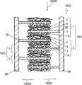
图1A是本发明的实施方式的双电层电容器1001的电容器元件1002的剖面图。图1B是双电层电容器1001的剖面图。图2是电容器元件1002的剖面放大图。如图1A和图2所示,电容器元件1002具有正极1和负极2。集电体3由铝箔等金属箔制成,具有面3A和面3A的背面3B。正极1和负极2含有:集电体3、设置在集电体3的除了一端3D以外的其余面3A上的主要含有作为碳系材料的活性炭粉末4A的可极化电极层4、设置在集电体3的除了一端3D以外的其余面3B上的主要含有活性炭粉末14A的可极化电极层14、和在可极化电极层4的面4D上结合的无纺布状的树脂层5。即,树脂层5具有彼此不规则结合在一起的纤维状。可极化电极层4具有位于集电体3的面3A上的面4E和面4E的背面4D。可极化电极层14具有位于集电体3的面3B上的面14D和面14D的背面14E。1A is a cross-sectional view of a
以集电体3的一端3D交替朝向相反方向1002A、1002B的方式来叠放负极1和负极2,制作电容器单元1003。层叠多个电容器单元1003,以使正极1的集电体的一端3D与集电板6A连接、使负极2的集电体3的一端3D与集电板6B连接的方式制作电容器元件1002。如图1B所示,双电层电容器1001具有电容器元件1002、驱动用电解液51、和收纳电容器元件1002和驱动用电解液51的金属制壳体52。The
下面,对双电层电容器1001的制造方法进行说明。Next, a method of manufacturing electric double layer capacitor 1001 will be described.
在盐酸系蚀刻液中对厚度约22μm的高纯度的铝箔进行电解蚀刻,使表面粗糙化,制作集电体3。A high-purity aluminum foil having a thickness of about 22 μm was subjected to electrolytic etching in a hydrochloric acid-based etching solution to roughen the surface, thereby producing the
准备平均粒径5μm的酚树脂系的活性炭粉末4A、14A。准备平均粒径0.05μm的由乙炔黑构成的导电性赋予剂4B、14B。准备由羧甲基纤维素(CMC)和聚四氟乙烯(PTFE)形成的粘合剂4C、14C。准备由甲醇和水混合而成的分散溶剂。将10重量份的活性炭粉末4A(14A)、2重量份的导电性赋予剂4B(14B)、和1重量份的粘合剂4C(14C)混合,一边用混炼机混炼,一边一点点地加入分散溶剂,制作具有规定粘度的糊剂。以包含集电体3的一端3D的面3A、3B的部分3E、3F露出的方式将该糊剂涂布在面3A、3B上。将涂有糊剂的集电体3在85℃的温度下大气中干燥5分钟,从而在集电体3的面3A、3B上分别形成可极化电极层4、14。Phenolic resin-based activated carbon powders 4A and 14A having an average particle diameter of 5 μm were prepared. Conductivity-imparting agents 4B and 14B made of acetylene black with an average particle diameter of 0.05 μm were prepared. Adhesives 4C and 14C made of carboxymethylcellulose (CMC) and polytetrafluoroethylene (PTFE) were prepared. Prepare a dispersion solvent that is a mixture of methanol and water.
接着,使用以下方法在可极化电极层4的面4D上结合树脂层5。树脂可以使用热塑性树脂。使用高温、高速的空气流将熔融的聚对苯二甲酸丁二醇酯(PBT)等热塑性树脂从具有多孔的口模吹出。吹出的树脂呈非常细的纤维状,收集在可极化电极层4的面4D上形成树脂层5。收集的纤维状的树脂具有无纺布形状,即具有彼此不规则结合在一起的纤维形状。树脂层5的收集的非常细的纤维状树脂以在可极化电极层4的面4D的凹凸内交缠在一起的方式结合。树脂层5具有约10μm的厚度。形成树脂层5之后,将形成有可极化电极层4、14和树脂层5的集电体3切成规定的尺寸,制作正极1和负极2。Next, the
然后,以正极1的集电体3的一端3D和负极2的集电体3的一端3D交替朝向相反的方向1002A、1002B的方式重叠正极1和负极2,制作多个电容器单元1003。此时,正极1的树脂层5位于负极2的可极化电极层14的面14E上。然后以正极1的树脂层5位于负极2的可极化电极层14的面14E上的方式层叠多个电容器单元1003。然后利用激光焊接将正极1的集电体3的一端3D连接在集电板6A上,并利用激光焊接将负极2的集电体3的一端3D连接在集电板6B上,制作电容器元件1002。Then, the
然后将集电板6A、6B分别与端子53A、53B连接。然后将电容器元件1002和驱动用电解液51从开口部52A装入、收纳在由铝等金属构成的壳体52内,使驱动用电解液51浸渗到电容器元件1002中。作为驱动用电解液51可以使用例如溶解有四乙基四氟硼酸铵的碳酸亚丙酯。Then,
然后在壳体52的开口部52A中嵌入封口橡胶54。端子53A、53B穿过设置在封口橡胶中的贯穿孔54A、54B,在壳体52的外部露出。然后,将壳体52的开口部52A附近的外围向壳体52的内侧拉深成圆环状,并且对金属壳体52的开口端进行卷边加工,使开口部52A密封,从而得到双电层电容器1001。Then, the sealing rubber 54 is fitted into the opening 52A of the housing 52 . The terminals 53A, 53B pass through the through holes 54A, 54B provided in the sealing rubber, and are exposed outside the case 52 . Then, the outer periphery near the opening 52A of the case 52 is drawn into a ring shape inwardly of the case 52, and the opening end of the metal case 52 is crimped to seal the opening 52A, thereby obtaining a double battery. layer capacitor 1001.
对于实施方式的双电层电容器1001而言,正极1、负极2,尤其是集电体3可以确保电容器单元1003的机械强度,集电板6A、6B可以确保电容器元件1002的机械强度,所以树脂层5不需要作为隔膜的机械强度,仅保证绝缘性即可。For the electric double layer capacitor 1001 of the embodiment, the
双电层电容器1001中,树脂层5通过氢键与可极化电极层4牢固地固定在一起。因此,作为树脂层5的材料使用的树脂是可以与可极化电极层4形成氢键的树脂。作为树脂层5的材料的树脂,为了形成氢键,优选化学式中含有卤素的树脂,除了可以使用聚对苯二甲酸丁二醇酯(PBT)以外,还可以使用聚乙烯(PE)、聚丙烯(PP)、聚对苯二甲酸乙二醇酯(PET)、聚苯硫醚(PPS)、聚芳酰胺、聚酰亚胺、尼龙、改性PP、改性PE、聚1,1-二氟乙烯(PVDF)、聚四氟乙烯(PTFE)等树脂。这些树脂可以通过氢键以较大的结合强度与可极化电极层4结合。进而,从耐热性的观点来看,作为树脂层5的材料树脂更优选PBT、PET、PPS、聚芳酰胺、聚酰亚胺、尼龙、PVDF、PTFE。In the electric double layer capacitor 1001, the
以往的双电层电容器具有作为独立于可极化电极层的部件的隔膜,其最低厚度为25μm。取代隔膜而使用树脂层5的实施方式中的双电层电容器1001的最低厚度可以为10μm以下,可以得到厚度薄、体积小、电容大的双电层电容器1001。Conventional electric double layer capacitors have a separator as a member independent of the polarizable electrode layer, and the minimum thickness thereof is 25 μm. The minimum thickness of the electric double layer capacitor 1001 in the embodiment in which the
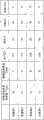
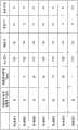
使用上述方法制作双电层电容器1001的实施例1~9和比较例1、2的样品,这些样品含有具有各种厚度T1的可极化电极层4、14和具有各种厚度T2的树脂层5。这些样品的电容器元件1002是直径18mm、长度50mm的圆筒卷绕型单体(cell)。评价这些样品中的树脂层5和可极化电极层4的接合程度,测定电容和电阻,结果示于图3A和图3B中。电容是,流通1分钟使样品充满电并且完全放电那样大的恒定电流,外加恒定电压,计算出充电后以恒定电流放电时的电容和电阻。Samples of Examples 1 to 9 and Comparative Examples 1, 2 of the electric double layer capacitor 1001 having polarizable electrode layers 4, 14 having various thicknesses T1 and resin layers having various thicknesses T2 were fabricated using the
树脂层5和可极化电极层4之间的接合程度按照JIS-K6854-1的“接合剂·剥离接合强度试验方法-第一部:90度剥离”中规定的标准进行评价。在图3A和图3B中,将发现树脂层5的破裂、可极化电极层4和树脂层5之间的剥离的样品记作“NG”,将没发现剥离的样品记作“OK”。The degree of bonding between the
实施例1~9的样品的树脂层5的厚度T2相对于可极化电极层4、14的厚度T1的比值R1在0.03~2.00的范围。这样的样品,可极化电极层4、14和树脂层5之间没有剥离,电容、电阻均显示出良好的值。特别是实施例1、2、4、5、8的样品,具有厚度比以往的双电层电容器的隔膜的厚度20μm小的、厚10μm的树脂层5。In the samples of Examples 1 to 9, the ratio R1 of the thickness T2 of the
另外,以纤维素为主要原料的以往的双电层电容器的隔膜的可批量生产的厚度为25μm。将纤维状的树脂层5与可极化电极层4一体化支撑的实施方式的双电层电容器1001,其树脂层5的厚度可以为20μm以下。In addition, the mass-producible thickness of the separator of a conventional electric double layer capacitor using cellulose as a main raw material is 25 μm. In the electric double layer capacitor 1001 of the embodiment in which the
比较例1的样品,比值R1为2.50,是较大的值,17N/m的力可使树脂层5内发生剥离。在比值R1是这样大的值的情况中,树脂层5本身的强度小。这种树脂层5在为了制作电容器元件而卷绕电容器单元时,树脂层5容易剥离,有时正极1和负极2短路。通过使形成树脂层5的纤维状的树脂与可极化电极层4物理性地交缠在一起,可以得到可极化电极层4和树脂层5之间的接合力。随着树脂层5的厚度T2相对于可极化电极层4的厚度T1的比值R1变大,树脂层5的纤维状的树脂中出现了不能与可极化电极层4交缠的树脂,由此可以认为树脂层5本身出现分离。In the sample of Comparative Example 1, the ratio R1 was 2.50, which is a relatively large value, and the inside of the
比较例2的样品,比值R1是较小的值,为0.013,其电容显著变小,电阻变大。可以认为是由于该样品的树脂层5不能保持大量的驱动用电解液,所以电容变小,电阻变大。In the sample of Comparative Example 2, the ratio R1 was a small value of 0.013, and the capacitance was remarkably small and the resistance was large. It is considered that the
实施方式的双电层电容器1001,通过树脂层5的纤维状树脂和可极化电极层4、14物理性彼此交缠,可以得到物理结合力。进而,通过可极化电极层4、14的面4D、14E上的主要的羟基、羧基与树脂层5的纤维状树脂的面的主要的羟基、羧基形成氢键,可以得到化学结合力。通过该物理结合力和化学结合力可以将树脂层5和可极化电极层4、14牢固地接合起来。In the electric double layer capacitor 1001 according to the embodiment, the fibrous resin of the
图4是实施方式的另一双电层电容器1004的立体图。图4中,对于与图1A和图1B所示的双电层电容器1001相同的部分使用相同的参照标记,并省略其说明。双电层电容器1004具有将正极1和负极2层叠卷绕而得到的卷绕型电容器元件1005。正极1和负极2分别与端子63A、63B连接。将与端子63A、63B连接的电容器元件1005与驱动用电解液61一起收纳在金属制的壳体62中。壳体62的开口部2被封口橡胶64密封。封口橡胶64上形成有贯穿孔64A、64B。端子63A、63B穿过贯穿孔64A、64B在壳体62的外部露出。双电层电容器1004中正极1和负极2的树脂层5与可极化电极层4、14借助物理结合力和化学结合力牢固接合,所以可以容易制作卷绕型电容器元件1005。与叠层型电容器元件1002相比,卷绕型电容器元件1005可以以更高的生产率、以便宜价格制作,在以大电流急速充放电时可以有效释放产生的热。因此,具有卷绕型电容器元件1005的双电层电容器1004可以在混合动力车、动力铲、起重机等产业用机器等流通大电流的机器中使用。FIG. 4 is a perspective view of another electric
另外,实施方式的双电层电容器1001同时具有低电阻和大电容。In addition, the electric double layer capacitor 1001 of the embodiment has both low resistance and large capacitance.
双电层电容器1001的树脂层5完全不含有导致经时劣化的粘合剂。图3B所示的实施例7的样品具有厚度T2为25μm的树脂层5。即可以使实施方式的双电层电容器1001的树脂层5的厚度T2为20μm以上。实施例7的样品,与具有隔膜的以往的电容器相比,初始电容和初始电阻程度相同,可以大幅抑制容量的经时降低和电阻的经时增大。以往的电容器的隔膜为了保持形状而含有粘合剂。该粘合剂在充放电时分解,附着并滞留在极化电极附近。可以认为这导致了电容器的电容减少和电阻增大。The
由于实施方式的双电层电容器1001的树脂层5完全不含有粘合剂,所以可以抑制粘合剂引起的容量的经时降低和电阻的经时增大。Since the
图5是实施方式的另一电容器元件1005的剖面放大图。图5中,对于与图2所示的电容器元件1002相同的部分使用相同的参照标记,并省略其说明。图2所示的电容器元件1002的正极1和负极2中,树脂层5与可极化电极层4的面4D结合。图5所示的电容器元件1005的正极1、负极2还具有在可极化电极层14的面14E上结合的树脂层15。树脂层15具有与树脂层5相同的结构,与可极化电极层14的面14E结合。在图1A、图1B所示的电容器元件1002中树脂层5、15彼此重合。树脂层5隔着可极化电极层4面向集电体3的面3A。树脂层15隔着可极化电极层14面向集电体3的面3B。FIG. 5 is an enlarged cross-sectional view of another
在图5所示的电容器元件1005中,树脂层5、15还可以由耐酸性强的树脂构成。通过耐酸性强可以抑制正极1的劣化。作为耐酸性强的树脂,可以使用PE、PP、PVDF、PET、PBT、PPS、聚芳酰胺、改性PP、改性PE等,优选使用PP、改性PP,更优选使用PET、PBT、PPS、聚芳酰胺,由此可以提高耐热性。In the
另外,改性PP、改性PE只要比通常的PP、PE耐酸性、耐碱性、甚至耐热性更高即可,可以使用酸改性PP、酸改性PE。酸改性可以列举出羧酸改性、马来酸改性,优选羧酸改性。In addition, modified PP and modified PE need only be higher in acid resistance, alkali resistance, or even heat resistance than ordinary PP and PE, and acid-modified PP and acid-modified PE can be used. Examples of acid modification include carboxylic acid modification and maleic acid modification, preferably carboxylic acid modification.
另外,在图5所示的电容器元件1005中,树脂层5、15可以由耐碱性强的树脂构成。通过强耐碱性可以抑制负极2的老化。作为耐碱性强的树脂,可以使用纤维素系树脂、PP、PBT、PPS、聚酰胺、聚芳酰胺,更优选使用纤维素系树脂、PP、PBT、PPS等。In addition, in the
另外,在图5所示的电容器元件1005中,树脂层5可以由耐酸性强的树脂构成,树脂层15可以由耐碱性强的树脂构成。在电容器单元1003、电容器元件1002中,树脂层5与树脂层15接触。由此具有强耐酸性和强耐碱性两者。图5所示的电极可以作为正极1和负极2的任一者使用。同样,树脂层15可以由耐酸性强的树脂构成,树脂层5可以由耐碱性强的树脂构成。In addition, in the
另外,树脂层5、15也可以由耐酸性强的树脂和耐碱性强的树脂的混合材料形成。In addition, the resin layers 5 and 15 may be formed of a mixed material of a resin with strong acid resistance and a resin with strong alkali resistance.
另外,可以在构成树脂层5的树脂的熔点以上的温度加热正极1和负极2。由此,树脂层5的一部分熔融,从可极化电极层4的面4D渗入到可极化电极层4的内部,所以可以进一步提高树脂层5和可极化电极层4的结合强度。树脂层5的熔融部分可以与集电体3从可极化电极层4露出的部分3E接触并熔接,由此可以以高强度固定树脂层5和集电体3,更牢固地与可极化电极层4固定。In addition, the
双电层电容器1001中,与正极1接合的集电板6A和与负极2接合的集电板6B与端子53A、53B接合。端子53A、53B也可以分别与正极1和负极2的集电体3的一端3D直接接合。In electric double layer capacitor 1001 ,
图6A是实施方式的另一电容器元件1006的剖面放大图。图6A中,对于与图5所示的电容器元件1005相同的部分使用相同的参照标记,并省略其说明。电容器元件1006在没有设置可极化电极层4、14的从可极化电极层4、14露出的集电体3的部分3E上形成穿通面3A、3B的贯穿孔8A。与可极化电极层4的面4D结合的树脂层5穿过贯穿孔8A而延伸,具有与可极化电极层14结合并与树脂层15连接的部分9。由此可以增加树脂层5与可极化电极层4的接触面积,可以将树脂层5、15更牢固地固定在可极化电极层4、14上。FIG. 6A is an enlarged cross-sectional view of another
图6B是实施方式的另一电容器元件1007的剖面放大图。图6B中,对于与图2所示的电容器元件1002相同的部分使用相同的参照标记,并省略其说明。在电容器元件1007中,在可极化电极层4、14之间在集电体3上形成有穿通面3A、3B的贯穿孔8B。在为了在可极化电极层4上形成树脂层5而向可极化电极层4的面4D吹附树脂时,从集电体3的面3D经过贯穿孔8B吸引空气。通过这样,用于形成树脂层5的树脂进入到可极化电极层4中,并穿过贯穿孔8B到达可极化电极层14。通过这样,由树脂层5相同的材料形成非常细的纤维状树脂纤维9B,树脂纤维9B被设置在可极化电极层4内,穿过贯穿孔8B而到达可极化电极层14内。借助树脂纤维9B,可以更牢固地将树脂层5与可极化电极层4的面4D结合,可更切实地防止正极1和负极2的短路。FIG. 6B is an enlarged cross-sectional view of another capacitor element 1007 of the embodiment. In FIG. 6B , the same reference numerals are used for the same parts as those of the
图7是图1A所示的电容器元件1002的从1002C方向看到的平面图。在正极1的集电体3的部分3E上形成有2个贯穿孔12A。在负极2的集电体3的部分3E上形成有2个贯穿孔13A。2个贯穿孔12A的间隔与2个贯穿孔13A的间隔不同。FIG. 7 is a plan view of
将通过层叠各正极1和负极2而形成的多个电容器单元1003层叠,形成电容器元件1002。通过对准贯穿孔12A、13A的位置,可以用激光焊接以高精度将正极1和负极2的集电体3与集电板6A、6B连接。A
另外,图6A所示的电容器元件1006中,可以使用在集电体3上形成的贯穿孔8A作为贯穿孔12A、13A来对准位置。另外在图6B所示的电容器元件1007中,可以使用在集电体3上形成的贯穿孔8B作为贯穿孔12A、13A来对准位置。In addition, in
另外,贯穿孔12A、13A是椭圆形的,但也可以是圆形的。在贯穿孔12A、13A是椭圆形时,可以防止正极1、负极2的转动。另外,2个贯穿孔12A的间隔和2个贯穿孔13A的间隔可以相同,也可以不同,通过使它们的间隔不同,可以防止正极1、负极2的转动。In addition, although the through-holes 12A and 13A are elliptical, they may be circular. When the through holes 12A and 13A are elliptical, rotation of the
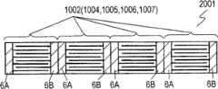
图8是实施方式的另一电容器元件2001的剖面图。图8中,对于与图1A所示的电容器元件1002相同的部分使用相同的参照标记,并省略其说明。电容器元件2001具有彼此连接的多个电容器元件1002(1004、1005、1006、1007)。电容器元件2002中,多个电容器元件1002(1004、1005、1006、1007)串联连接,但也可以用并联等其他方法连接。FIG. 8 is a cross-sectional view of another
实施方式的双电层电容器1001还适合作为具有集电体、设置在集电体的面上的碳系材料和在碳系材料内吸藏的锂离子的电容器使用。此时,需要在碳系材料内吸藏锂离子的工序(预掺杂工序)。在该工序中,在负极的可极化电极层的面上直接配置锂源的情况中,不能在负极的可极化电极层的面上设置树脂层,但可以在正极的可极化电极层的面上设置树脂层,具有同样的效果。Electric double layer capacitor 1001 according to the embodiment is also suitable for use as a capacitor having a current collector, a carbon-based material provided on a surface of the current collector, and lithium ions stored in the carbon-based material. In this case, a step of storing lithium ions in the carbon-based material (pre-doping step) is required. In this process, in the case where the lithium source is directly arranged on the surface of the polarizable electrode layer of the negative electrode, the resin layer cannot be provided on the surface of the polarizable electrode layer of the negative electrode, but can be placed on the polarizable electrode layer of the positive electrode. A resin layer is set on the surface of the surface, which has the same effect.
作为碳系材料内吸藏、脱附的离子,除了锂离子以外,还可以在电容器中使用钠离子、钾离子等碱金属、碱土金属、以及可在富勒烯中吸藏脱附的镧系离子等稀土类,这样的电容器也具有同样的效果。As ions that can be occluded and desorbed in carbon-based materials, in addition to lithium ions, alkali metals such as sodium ions and potassium ions, alkaline earth metals, and lanthanides that can be occluded and desorbed in fullerenes can also be used in capacitors. Rare earths such as ions, such capacitors also have the same effect.
另外,在碳系材料内不吸藏脱附阳离子而是吸藏脱附阴离子时,通过在发生吸藏脱附侧的电极相反侧的电极的电极层上设置树脂层,可以在短时间内完成预掺杂工序,具有单体电阻降低和单体电容增大的同样效果。In addition, when the carbon-based material does not store and desorb cations but stores and desorbs anions, it can be completed in a short time by providing a resin layer on the electrode layer of the electrode opposite to the electrode on which the occlusion and desorption occurs. The pre-doping process has the same effect of reducing the resistance of the single cell and increasing the capacitance of the single cell.
工业利用性Industrial availability
本发明的电容器厚度薄且体积小,特别是作为混合动力车、燃料电车的备用电源和再生用电容器是有用的。The capacitor of the present invention is thin and small, and is particularly useful as a backup power source and a regeneration capacitor for hybrid vehicles and fuel electric vehicles.
Claims (15)
Translated fromChineseApplications Claiming Priority (5)
| Application Number | Priority Date | Filing Date | Title |
|---|---|---|---|
| JP2007156025 | 2007-06-13 | ||
| JP156025/2007 | 2007-06-13 | ||
| JP2007156024 | 2007-06-13 | ||
| JP156024/2007 | 2007-06-13 | ||
| PCT/JP2008/001434WO2008152788A1 (en) | 2007-06-13 | 2008-06-05 | Capacitor |
Publications (2)
| Publication Number | Publication Date |
|---|---|
| CN101681723A CN101681723A (en) | 2010-03-24 |
| CN101681723Btrue CN101681723B (en) | 2012-11-14 |
Family
ID=40129403
Family Applications (1)
| Application Number | Title | Priority Date | Filing Date |
|---|---|---|---|
| CN2008800163463AExpired - Fee RelatedCN101681723B (en) | 2007-06-13 | 2008-06-05 | Capacitor |
Country Status (4)
| Country | Link |
|---|---|
| US (1) | US8693166B2 (en) |
| JP (1) | JP5359870B2 (en) |
| CN (1) | CN101681723B (en) |
| WO (1) | WO2008152788A1 (en) |
Families Citing this family (3)
| Publication number | Priority date | Publication date | Assignee | Title |
|---|---|---|---|---|
| WO2015013615A2 (en) | 2013-07-25 | 2015-01-29 | Drexel University | Knitted electrochemical capacitors and heated fabrics |
| KR20190069892A (en)* | 2017-12-12 | 2019-06-20 | 한국제이씨씨(주) | Electric double layer capacitor |
| CN114284471A (en)* | 2021-12-23 | 2022-04-05 | 湖北亿纬动力有限公司 | Negative pole piece and preparation method and application thereof |
Citations (1)
| Publication number | Priority date | Publication date | Assignee | Title |
|---|---|---|---|---|
| JP2003109654A (en)* | 2001-09-28 | 2003-04-11 | Matsushita Electric Ind Co Ltd | Electrode for battery and method of manufacturing the same |
Family Cites Families (7)
| Publication number | Priority date | Publication date | Assignee | Title |
|---|---|---|---|---|
| JPS6414882A (en) | 1987-07-08 | 1989-01-19 | Mitsubishi Gas Chemical Co | Secondary battery |
| JPH08107048A (en) | 1994-08-12 | 1996-04-23 | Asahi Glass Co Ltd | Electric double layer capacitor |
| JP3486968B2 (en)* | 1994-08-26 | 2004-01-13 | 株式会社ユアサコーポレーション | Manufacturing method of laminated battery |
| JPH10270293A (en) | 1997-03-26 | 1998-10-09 | Matsushita Electric Ind Co Ltd | Electric double layer capacitor |
| JP4178926B2 (en) | 2002-11-29 | 2008-11-12 | 日産自動車株式会社 | Bipolar battery, bipolar battery manufacturing method, battery pack and vehicle |
| JP2006286919A (en)* | 2005-03-31 | 2006-10-19 | Fuji Heavy Ind Ltd | Lithium ion capacitor |
| JP4613953B2 (en)* | 2005-12-28 | 2011-01-19 | パナソニック株式会社 | Nonaqueous electrolyte secondary battery |
- 2008
- 2008-06-05WOPCT/JP2008/001434patent/WO2008152788A1/enactiveApplication Filing
- 2008-06-05USUS12/599,557patent/US8693166B2/ennot_activeExpired - Fee Related
- 2008-06-05CNCN2008800163463Apatent/CN101681723B/ennot_activeExpired - Fee Related
- 2008-06-05JPJP2009519152Apatent/JP5359870B2/ennot_activeExpired - Fee Related
Patent Citations (1)
| Publication number | Priority date | Publication date | Assignee | Title |
|---|---|---|---|---|
| JP2003109654A (en)* | 2001-09-28 | 2003-04-11 | Matsushita Electric Ind Co Ltd | Electrode for battery and method of manufacturing the same |
Also Published As
| Publication number | Publication date |
|---|---|
| US8693166B2 (en) | 2014-04-08 |
| US20110128672A1 (en) | 2011-06-02 |
| CN101681723A (en) | 2010-03-24 |
| JP5359870B2 (en) | 2013-12-04 |
| JPWO2008152788A1 (en) | 2010-08-26 |
| WO2008152788A1 (en) | 2008-12-18 |
Similar Documents
| Publication | Publication Date | Title |
|---|---|---|
| CN102771007B (en) | Power storage device unit, manufacturing method, storage method thereof, and power storage device | |
| JP4753369B2 (en) | Stacked electrochemical device | |
| JPWO2004097867A1 (en) | Organic electrolyte capacitor | |
| JPWO2006068291A1 (en) | Electric double layer capacitor | |
| JP6401197B2 (en) | Electrochemical device and method for producing electrochemical device | |
| KR102062123B1 (en) | Electrochemical device | |
| JP2012138408A (en) | Electrochemical device and manufacturing method thereof | |
| JP6401198B2 (en) | Electrochemical device and method for producing electrochemical device | |
| JP6684034B2 (en) | Electrochemical device and method for manufacturing electrochemical device | |
| JP4986241B2 (en) | Electrochemical device and manufacturing method thereof | |
| JP2011159642A (en) | Electrochemical device | |
| JP4931239B2 (en) | Power storage device | |
| CN101681723B (en) | Capacitor | |
| CN108666632B (en) | Electrochemical device | |
| JP2007201248A (en) | Laminated electrochemical device | |
| JP2007287724A (en) | Laminated electrochemical device | |
| JP2018148230A (en) | Electrochemical device and electrochemical device manufacturing method | |
| JP2010114364A (en) | Electrochemical device, and electrochemical device module | |
| JP2014120760A (en) | Super capacitor and manufacturing method of the same | |
| JP2010192885A (en) | Manufacturing method of capacitor, and capacitor | |
| JP2011258798A (en) | Electrochemical device | |
| JP2010182922A (en) | Electric double layer capacitor and method of manufacturing electric double layer capacitor | |
| JP2009088279A (en) | Electrochemical device | |
| TWI292163B (en) | ||
| JP5845896B2 (en) | Power storage device |
Legal Events
| Date | Code | Title | Description |
|---|---|---|---|
| C06 | Publication | ||
| PB01 | Publication | ||
| C10 | Entry into substantive examination | ||
| SE01 | Entry into force of request for substantive examination | ||
| C14 | Grant of patent or utility model | ||
| GR01 | Patent grant | ||
| CF01 | Termination of patent right due to non-payment of annual fee | Granted publication date:20121114 Termination date:20190605 | |
| CF01 | Termination of patent right due to non-payment of annual fee |