CN101680861B - flow distribution valve - Google Patents
flow distribution valveDownload PDFInfo
- Publication number
- CN101680861B CN101680861BCN200880016262XACN200880016262ACN101680861BCN 101680861 BCN101680861 BCN 101680861BCN 200880016262X ACN200880016262X ACN 200880016262XACN 200880016262 ACN200880016262 ACN 200880016262ACN 101680861 BCN101680861 BCN 101680861B
- Authority
- CN
- China
- Prior art keywords
- port
- rotor
- stator
- valve
- orifice
- Prior art date
- Legal status (The legal status is an assumption and is not a legal conclusion. Google has not performed a legal analysis and makes no representation as to the accuracy of the status listed.)
- Expired - Fee Related
Links
Images


Classifications
- F—MECHANICAL ENGINEERING; LIGHTING; HEATING; WEAPONS; BLASTING
- F16—ENGINEERING ELEMENTS AND UNITS; GENERAL MEASURES FOR PRODUCING AND MAINTAINING EFFECTIVE FUNCTIONING OF MACHINES OR INSTALLATIONS; THERMAL INSULATION IN GENERAL
- F16K—VALVES; TAPS; COCKS; ACTUATING-FLOATS; DEVICES FOR VENTING OR AERATING
- F16K11/00—Multiple-way valves, e.g. mixing valves; Pipe fittings incorporating such valves
- F16K11/02—Multiple-way valves, e.g. mixing valves; Pipe fittings incorporating such valves with all movable sealing faces moving as one unit
- F16K11/06—Multiple-way valves, e.g. mixing valves; Pipe fittings incorporating such valves with all movable sealing faces moving as one unit comprising only sliding valves, i.e. sliding closure elements
- F16K11/072—Multiple-way valves, e.g. mixing valves; Pipe fittings incorporating such valves with all movable sealing faces moving as one unit comprising only sliding valves, i.e. sliding closure elements with pivoted closure members
- F16K11/074—Multiple-way valves, e.g. mixing valves; Pipe fittings incorporating such valves with all movable sealing faces moving as one unit comprising only sliding valves, i.e. sliding closure elements with pivoted closure members with flat sealing faces
- F16K11/0743—Multiple-way valves, e.g. mixing valves; Pipe fittings incorporating such valves with all movable sealing faces moving as one unit comprising only sliding valves, i.e. sliding closure elements with pivoted closure members with flat sealing faces with both the supply and the discharge passages being on one side of the closure plates
- G—PHYSICS
- G01—MEASURING; TESTING
- G01N—INVESTIGATING OR ANALYSING MATERIALS BY DETERMINING THEIR CHEMICAL OR PHYSICAL PROPERTIES
- G01N30/00—Investigating or analysing materials by separation into components using adsorption, absorption or similar phenomena or using ion-exchange, e.g. chromatography or field flow fractionation
- G01N30/02—Column chromatography
- G01N30/04—Preparation or injection of sample to be analysed
- G01N30/16—Injection
- G01N30/20—Injection using a sampling valve
- G—PHYSICS
- G01—MEASURING; TESTING
- G01N—INVESTIGATING OR ANALYSING MATERIALS BY DETERMINING THEIR CHEMICAL OR PHYSICAL PROPERTIES
- G01N35/00—Automatic analysis not limited to methods or materials provided for in any single one of groups G01N1/00 - G01N33/00; Handling materials therefor
- G01N35/10—Devices for transferring samples or any liquids to, in, or from, the analysis apparatus, e.g. suction devices, injection devices
- G01N35/1095—Devices for transferring samples or any liquids to, in, or from, the analysis apparatus, e.g. suction devices, injection devices for supplying the samples to flow-through analysers
- G01N35/1097—Devices for transferring samples or any liquids to, in, or from, the analysis apparatus, e.g. suction devices, injection devices for supplying the samples to flow-through analysers characterised by the valves
- G—PHYSICS
- G01—MEASURING; TESTING
- G01N—INVESTIGATING OR ANALYSING MATERIALS BY DETERMINING THEIR CHEMICAL OR PHYSICAL PROPERTIES
- G01N30/00—Investigating or analysing materials by separation into components using adsorption, absorption or similar phenomena or using ion-exchange, e.g. chromatography or field flow fractionation
- G01N30/02—Column chromatography
- G01N30/04—Preparation or injection of sample to be analysed
- G01N30/16—Injection
- G01N30/20—Injection using a sampling valve
- G01N2030/202—Injection using a sampling valve rotary valves
- Y—GENERAL TAGGING OF NEW TECHNOLOGICAL DEVELOPMENTS; GENERAL TAGGING OF CROSS-SECTIONAL TECHNOLOGIES SPANNING OVER SEVERAL SECTIONS OF THE IPC; TECHNICAL SUBJECTS COVERED BY FORMER USPC CROSS-REFERENCE ART COLLECTIONS [XRACs] AND DIGESTS
- Y10—TECHNICAL SUBJECTS COVERED BY FORMER USPC
- Y10T—TECHNICAL SUBJECTS COVERED BY FORMER US CLASSIFICATION
- Y10T137/00—Fluid handling
- Y10T137/8593—Systems
- Y10T137/86493—Multi-way valve unit
- Y10T137/86558—Plural noncommunicating flow paths
- Y—GENERAL TAGGING OF NEW TECHNOLOGICAL DEVELOPMENTS; GENERAL TAGGING OF CROSS-SECTIONAL TECHNOLOGIES SPANNING OVER SEVERAL SECTIONS OF THE IPC; TECHNICAL SUBJECTS COVERED BY FORMER USPC CROSS-REFERENCE ART COLLECTIONS [XRACs] AND DIGESTS
- Y10—TECHNICAL SUBJECTS COVERED BY FORMER USPC
- Y10T—TECHNICAL SUBJECTS COVERED BY FORMER US CLASSIFICATION
- Y10T137/00—Fluid handling
- Y10T137/8593—Systems
- Y10T137/86493—Multi-way valve unit
- Y10T137/86863—Rotary valve unit
Landscapes
- Physics & Mathematics (AREA)
- Health & Medical Sciences (AREA)
- Life Sciences & Earth Sciences (AREA)
- Chemical & Material Sciences (AREA)
- Analytical Chemistry (AREA)
- Biochemistry (AREA)
- General Health & Medical Sciences (AREA)
- General Physics & Mathematics (AREA)
- Immunology (AREA)
- Pathology (AREA)
- Engineering & Computer Science (AREA)
- General Engineering & Computer Science (AREA)
- Mechanical Engineering (AREA)
- Multiple-Way Valves (AREA)
- Sampling And Sample Adjustment (AREA)
Abstract
Description
Translated fromChinese技术领域technical field
本发明涉及阀,并且更具体地涉及用于在流量分配装置(例如液相色谱系统)中引导流体流的旋转阀。The present invention relates to valves, and more particularly to rotary valves for directing fluid flow in flow distribution devices such as liquid chromatography systems.
背景技术Background technique
阀通常用在涉及流体的输送的装置中。一种典型的用途是将流体引导到多个可能的流路的其中一个中。例如,在实验室用的液相色谱系统领域中,其中流路典型地具有在0.25-2毫米范围内的内径,双通电磁阀通常被用于引导流体。此类阀的示例是能够从日本名古屋的TAKASAGO Electrical Inc.获得的MTV系列阀。Valves are commonly used in devices involving the transfer of fluids. A typical use is to direct fluid into one of several possible flow paths. For example, in the field of laboratory liquid chromatography systems, where the flow path typically has an inner diameter in the range of 0.25-2 mm, two-way solenoid valves are often used to direct the fluid. An example of such a valve is the MTV series valve available from TAKASAGO Electrical Inc. of Nagoya, Japan.
当在流体压力相对较高(诸如超过大约0.5MPa的压力)的应用中使用时,电磁阀易于有限制。Solenoid valves are prone to restriction when used in applications where the fluid pressure is relatively high, such as pressures in excess of about 0.5 MPa.
另外,它们不是很适合用作多流路阀,即具有多于一个同时使用的入口/出口的阀。Additionally, they are not well suited for use as multi-flow valves, ie valves with more than one inlet/outlet used simultaneously.
对于此类应用而言,在现有技术中使用旋转阀是众所周知的。通常,旋转阀具有静止本体(本文中所谓的定子),该静止本体与旋转本体(在本文中称为转子)协作。For such applications the use of rotary valves is well known in the art. Typically, a rotary valve has a stationary body (herein called a stator) cooperating with a rotating body (herein called a rotor).
定子设有多个入口端口和出口端口。这些端口通过孔与内部定子表面上的相应的一套孔口成流体连通。内部定子表面是与转子的内部转子表面成流体密封接触的定子的内部表面。转子典型地形成为盘,而内部转子表面以旋转协作的方式压靠内部定子表面。内部定子表面设有一个或者多个沟槽,沟槽依靠转子相对于定子的旋转位置而与不同的孔口互相连接。The stator is provided with a plurality of inlet and outlet ports. These ports are in fluid communication through holes with a corresponding set of orifices on the inner stator surface. The inner stator surface is the inner surface of the stator that is in fluid-tight contact with the inner rotor surface of the rotor. The rotor is typically formed as a disk, and the inner rotor surface is pressed against the inner stator surface in a rotationally cooperating manner. The inner stator surface is provided with one or more grooves which interconnect with different orifices depending on the rotational position of the rotor relative to the stator.
旋转阀能够被设计成经受高压(诸如超过30MPa的压力)。它们能够由诸如不锈钢、高性能聚合材料以及陶瓷的多种材料制成。Rotary valves can be designed to withstand high pressures (such as pressures in excess of 30 MPa). They can be made from a variety of materials such as stainless steel, high performance polymers, and ceramics.
转子或者定子中入口/出口的数量以及沟槽的设计反映了特定阀的使用意图。The number of inlets/outlets and groove design in the rotor or stator reflect the intended use of a particular valve.
一种常见类型的多用途阀具有一个入口端口(典型地放置在阀的旋转轴线上)和围绕着入口端口等距地放置的多个出口端口。转子具有单个径向延伸的沟槽,沟槽的一端位于转动中心,从而总是与入口连接,而另一端依靠转子相对于定子的角度位置连接到其中任何一个出口上。此类阀用来将流从入口引导到其中任何出口——一次一个出口。A common type of multi-purpose valve has an inlet port (typically placed on the axis of rotation of the valve) and outlet ports equidistantly placed around the inlet port. The rotor has a single radially extending slot, one end of which is at the center of rotation so as to always be connected to the inlet and the other end is connected to either of the outlets depending on the angular position of the rotor relative to the stator. Such valves are used to direct flow from an inlet to any of the outlets - one outlet at a time.
可能有更复杂的布置。例如,可能有益的是允许多于一个流体经过阀或者允许流多于一次地经过相同的阀。已经设计出解决多种此类情形的阀。More complex arrangements are possible. For example, it may be beneficial to allow more than one fluid to pass through a valve or to allow flow to pass through the same valve more than once. Valves have been designed to address many of these situations.
此类阀的一个示例是双重随机通道(dual random access),授予Nichols的US6,672,336中描述了三通旋转阀。该阀解决了允许将第一流体引导到出口“A”或者出口“B”,并且将第二流体引导到出口“C”或者出口“D”的问题,这全部以单个阀来实施,这允许第一流体的方向独立于第二流体的方向。An example of such a valve is a dual random access, three-way rotary valve described in US 6,672,336 to Nichols. This valve solves the problem of allowing the first fluid to be directed to outlet "A" or outlet "B" and the second fluid to be directed to outlet "C" or outlet "D", all in a single valve, which allows The direction of the first fluid is independent of the direction of the second fluid.
对于流量分配系统可能需要解决的另一种情形是何时应将流以轮流的方式通过三个部件而引导,如图1和图2中所示。Another situation that may need to be addressed for a flow distribution system is when flow should be directed through three components in an alternating manner, as shown in FIGS. 1 and 2 .
第一部件、第二部件以及第三部件代表流应当经过其而被引导的任何部件(或者部件组),诸如传感器、色谱柱、其它阀等。The first, second and third components represent any component (or group of components) through which flow should be directed, such as sensors, chromatography columns, other valves, and the like.
假设穿过各部件的流方向不重要(或者实际上意图被切换),该情形可用传统的四通双路阀轻易地解决,示意性地显示在图3和图4中。Assuming that the direction of flow through the components is not important (or indeed intended to be switched), this situation can be easily resolved with a conventional four-way two-way valve, shown schematically in FIGS. 3 and 4 .
但是,图3和图4的解决方案在穿过其中一个部件(图中的第二部件)的流向必须不改变的情况下是无用的。该情形示意性地示出在图5(其与图1类似)和图6中。However, the solutions of Figures 3 and 4 are useless if the flow direction through one of the components (the second in the figure) must not change. This situation is shown schematically in FIG. 5 (which is similar to FIG. 1 ) and FIG. 6 .
对于其流向具有重要性(即,对于依赖于流向的流体具有不同特性或不同影响的部件)的部件的示例(取自液相色谱领域)是具有非对称内部室、色谱柱、球阀等的传感器。Examples (taken from the field of liquid chromatography) of components for which the direction of flow is important (i.e. have different properties or different effects on the fluid depending on the direction of flow) are sensors with asymmetric internal chambers, columns, ball valves, etc. .
因此,需要这样的单个阀,在第一位置:Therefore, such a single valve is required, in the first position:
该阀从源引导流穿过第一部件、第二部件、第三部件并穿过出口流出;the valve directs flow from the source through the first component, the second component, the third component and out through the outlet;
并且在第二位置:and in the second position:
该阀从源引导流穿过第三部件、第二部件、第一部件并穿过出口流出。The valve directs flow from the source through the third component, the second component, the first component and out through the outlet.
同时允许该流在所述第一位置和第二位置均沿着相同流向经过该第二部件。At the same time the flow is allowed to pass through the second member in the same flow direction at both said first location and said second location.
发明内容Contents of the invention
该需要用根据本发明的权利要求1的流量分配阀而解决。This need is solved with a flow distribution valve according to claim 1 of the invention.
此外,根据本发明的第二方面,描述了根据权利要求4的色谱系统,所述色谱系统包括根据权利要求1的阀。Furthermore, according to a second aspect of the present invention, a chromatography system according to claim 4 comprising a valve according to claim 1 is described.
附图说明Description of drawings
图1是以第一模式穿过三个部件的流的示意性视图。Figure 1 is a schematic view of flow through three components in a first mode.
图2是以第二模式穿过三个部件的流的示意性视图。Figure 2 is a schematic view of flow through three components in a second mode.
图3是以第一模式使用传统阀穿过三个部件的流的示意性视图。Figure 3 is a schematic view of flow through three components using a conventional valve in a first mode.
图4是以第二模式使用传统阀穿过三个部件的流的示意性视图。Figure 4 is a schematic view of flow through three components using a conventional valve in a second mode.
图5是以第一模式穿过三个部件的流的示意性视图。Figure 5 is a schematic view of flow through three components in a first mode.
图6是以第二模式穿过三个部件的流的示意性视图。Figure 6 is a schematic view of flow through three components in a second mode.
图7是旋转阀的示意性侧视图。Fig. 7 is a schematic side view of a rotary valve.
图8是根据本发明的一个实施例进/出阀的入口/出口的示意性视图。Figure 8 is a schematic view of an inlet/outlet of an inlet/outlet valve according to one embodiment of the present invention.
图9是示出在图8中的定子的示意性主视图。FIG. 9 is a schematic front view of the stator shown in FIG. 8 .
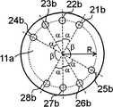
图10示意性地显示了示出在图8和图9中的定子的内部定子表面的孔口的角分布。FIG. 10 schematically shows the angular distribution of the apertures of the inner stator surface of the stator shown in FIGS. 8 and 9 .
图11是图8的定子的示意性视图,显示了内部定子表面。Figure 11 is a schematic view of the stator of Figure 8, showing the inner stator surfaces.
图12是显示在图8-11中的定子的透视图,显示了隐藏的孔口和通道。Figure 12 is a perspective view of the stator shown in Figures 8-11 showing hidden apertures and channels.
图13是显示在图11中的内部定子表面的示意性视图,还显示了沟槽端部的位置。Figure 13 is a schematic view of the inner stator surface shown in Figure 11, also showing the location of the ends of the slots.
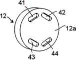
图14是根据本发明的一个实施例的转子的内部转子表面的示意性视图。所述转子适于与如图8-13中所示的定子协作。Figure 14 is a schematic view of an inner rotor surface of a rotor according to one embodiment of the invention. The rotor is adapted to cooperate with a stator as shown in Figures 8-13.
图15示意性地显示了显示在图14中的转子的沟槽的角分布。FIG. 15 schematically shows the angular distribution of the grooves of the rotor shown in FIG. 14 .
图16是显示在图8-15中的根据本发明一个实施例的阀的第一转子位置的透视图。Figure 16 is a perspective view of the valve shown in Figures 8-15 in a first rotor position according to one embodiment of the present invention.
图17是显示在图16中的阀的转子位置的示意性的主视图。FIG. 17 is a schematic front view showing the rotor position of the valve in FIG. 16 .
图18是根据显示在图8-15中的本发明的实施例的阀的第二转子位置的透视图。18 is a perspective view of a second rotor position of the valve according to the embodiment of the invention shown in FIGS. 8-15.
图19是显示在图18中的阀的转子位置的示意性的主视图。FIG. 19 is a schematic front view showing the rotor position of the valve in FIG. 18 .
图20是以第一模式使用根据本发明的阀的色谱系统的示意性视图。Figure 20 is a schematic view of a chromatography system using a valve according to the invention in a first mode.
图21是以第二模式使用根据本发明的阀的色谱系统的示意性视图。Figure 21 is a schematic view of a chromatography system using a valve according to the invention in a second mode.
图22是使用根据本发明的阀的延伸的色谱系统的示意性视图。Figure 22 is a schematic view of an extended chromatography system using a valve according to the present invention.
具体实施方式Detailed ways
典型的旋转阀的主要部分示意性地显示在图7中(其中没有显示支架或者类似的支承或紧固元件)。旋转阀10具有定子11、转子12、旋转轴13以及驱动单元14,旋转轴13可选地可设有用于识别其角度位置的构件(未显示),而驱动单元14典型地包括齿轮箱和马达(尽管阀也可以手动操作)。转子能够围绕着阀的旋转轴线RA相对于定子旋转。The main parts of a typical rotary valve are shown schematically in Figure 7 (where brackets or similar supporting or securing elements are not shown). The
定子11相对于将该定子构造在其中的装置而固定,定子11设有用于与流体源流体连通的端口(未显示在图7中)和阀将与其协作的任何部件。端口可被定位在定子的任何适当部分上,并且可沿着任何适当的方向定位。端口设有用来连接毛细管或者管子的构件。此类构件可以为任何适当的类型,诸如对于本领域技术人员而言公知的传统的Valco接头。端口通过通道与内部定子表面11a(即在运行期间与转子12接触的该表面)上相应的一套孔口成流体连通。The
转子12典型地形成为盘并具有内部转子表面12a,内部转子表面12a是在运行期间压靠内部定子表面11a的表面。内部转子表面12a设有一个或者多个沟槽,这些沟槽依靠转子相对于定子的转子位置与内部定子表面11a的不同孔口互相连接。The
图8示出了根据本发明的一个实施例的流量分配阀的定子11的简化透视图,该图示出了阀的入口端口和出口端口布置。当解释这些端口的使用时,在本文中使用用语“上部”和“下部”。这些用语仅参考附图,因为阀的功能并不依靠其如何转动或者定位。但是,端口的相互位置(或者更确切地说将端口与转子连接的孔口的相互位置)是重要的。然而,根据本发明的一个实施例的定子11具有8各外部端口:第一端口21a、第二端口22a、第三端口23a、第四端口24a、第五端口25a、第六端口26a、第七端口27a以及第八端口28a,它们被用来将阀连接到所有期望的外围部件上。Figure 8 shows a simplified perspective view of the
本文中应当注意的是:用语“部件”可以表示一个单独的装置(诸如色谱柱)或者一套互相连接的装置(诸如多个串联的阀和监视器或者甚至简单地为一根互连管)。It should be noted here that the term "component" can refer to a single device (such as a chromatography column) or a set of interconnected devices (such as a number of valves and monitors in series or even simply an interconnected tube) .
图9是根据显示在图8中的实施例的定子11的主视图,限定了阀如何连接到外围部件上。流体从诸如泵的源进入第二端口22a。第一部件可以是阀、监视单元、维持毛细管回路或者具有入口和出口的任何其它有用的部件,第一部件通过第一端口21a和第六端口26a连接到阀上。Figure 9 is a front view of the
类似地,第三部件通过第三端口23a和第八端口28a连接到阀上。第五端口25a连接到第二部件的入口上,并且第七端口27a接受来自第二部件的出口流。最后,第四端口24a是出口端口,流体从该端口离开阀(流向任何另外的部件、容器或者被废弃)。Similarly, the third component is connected to the valve through the
应当注意的是:与第一部件相关的端口将依靠阀的转子位置而交替地充当入口/出口。这对于与第三部件相关的端口同样有效,尽管第五端口25a总是为到第二部件的出口端口,而第七端口27a总是为来自第二部件的入口端口。还应当注意的是:各端口通过通道连接到内部定子表面11a上。各端口将被连接到孔口上,即第一孔口21b连接到第一端口21a上,第二孔口22b连接到第二端口22a上,第三孔口23b连接到第三端口23a上,第四孔口24b连接到第四端口24a上,第五孔口25b连接到第五端口25a上,第六孔口26b连接到第六端口26a上,第七孔口27b连接到第七端口27a上,且第八孔口28b连接到第八端口28a上。尽管从附图中并非显而易见的,但是通道和内部定子表面上的其孔口典型地具有比端口自身更小的直径。It should be noted that the port associated with the first component will act alternately as inlet/outlet depending on the rotor position of the valve. The same is valid for the ports associated with the third component, although the
查看内部定子表面11a,孔口的通常角度分布示出在图10中(注意:出于清晰的原因,在该图中省略了任何定子沟槽,如以下将参考图13的描述)。在本发明的该实施例中的孔口的位置可分成两组描述:包括第一、第二、第三和第四孔口21b-24b的上部组,以及包括第五、第六、第七和第八孔口25b-28b的下部组。各个上部孔口21b-24b(对应于端口21a-24a)由角度α均等地分开,如各个下部孔口25b-28b(对应于端口25a-28a)。上部组的孔口21b-24b和下部组的孔口25b-28b在各侧分别用同样的角度β分开。在一个优选的实施例中,角度α为30度,而角度β为90度。但是,其它角度也是可能的,诸如α=36度并且β=72度。当然所有的孔口以到阀的旋转轴线的大致相同的径向距离R进行放置。Looking at the
为了获得期望的阀功能,除了孔口,内部定子表面11a还设有第一定子沟槽31和第二定子沟槽32,所述沟槽彼此大致平行,如图11所示(图10中未显示)。应当注意的是:第一定子沟槽31的一端连接到第四孔口24b上,即其与第一部件的一端成流体连通,而第二定子沟槽32的一端连接到第五孔口25b上,即其与第三部件的一端成流体连通。In order to obtain the desired valve function, in addition to the orifice, the
该布置还从定子的前侧显示在图12中,且孔口和沟槽由虚线指示。This arrangement is also shown in Figure 12 from the front side of the stator, with the apertures and slots indicated by dashed lines.
各定子沟槽31、32典型地具有与孔口直径一样的宽度,各定子沟槽31、32终止在与距离最近的孔口角度α的角部分(angularpartition)相对应的位置处,如图13所示出的,并且与该套孔口一样具有到阀的旋转轴线的相同的径向距离R。Each
适合与如上面关于图8-13中描述的定子协作的转子实施例的内部转子表面12a显示在图14中。其设有第一转子沟槽41、第二转子沟槽42、第三转子沟槽43以及第四转子沟槽44。第一转子沟槽41和第二转子沟槽42被称为上转子沟槽,而第三转子沟槽43和第四转子沟槽44被称为下转子沟槽。转子沟槽41-44优选地具有一样的相互尺寸和形状,并且如图15中所示以对应于定子11的孔口的方式成角度地分布,即两个上转子沟槽41、42的最靠近的端部由角度α分开,并且该套上转子沟槽和该套下转子沟槽在两个方向上均以角度β分开。各转子沟槽(41-44)延伸跨越隔开定子的两个相邻孔口的角度α。同时,内部转子表面12a的转子沟槽41-44的所有端部与内部定子表面11a的孔口一样以距离转子的中心大致相同的径向距离R放置。An
当组装时,内部转子表面12a以对于任何传统的旋转阀典型的方式(该方式对于本领域技术人员是众所周知的,将不在本文中进行解释)被压靠到内部定子表面11a上。转子相对于本发明的阀定子的位置使得两个可操作的转子位置可能,如图16-19所示。When assembled, the
如图16和17中所示,在第一转子位置中,流体典型地从泵进入第二端口22a。流经过第一转子沟槽41、通过第一端口21a离开、到达第一部件并从该第一部件通过第六端口26a返回。从那里,流体经过第三转子沟槽43,并通过第五端口25离开,以进入第二部件。流体从第二部件返回到阀的第七端口27a,经过第四转子沟槽44并通过第八端口28a离开,到达第三部件。流体从该第三部件返回到阀的第三端口23a、经过第二转子沟槽42并通过第四端口24a离开阀。As shown in Figures 16 and 17, in the first rotor position fluid typically enters the
应当注意的是:尽管上面没有描述,但是经过任何一个端口21a-28a的流体当然还会经过内部定子表面上的相应孔口21b-28b。还应当注意的是:在该转子位置中,除了分别连接到第四孔口24b和第五孔口25b的部分外,不使用内部定子表面11a的定子沟槽31和32。因此,如下面所述的,它们形成能够在第二转子位置中清洗的死胡同。It should be noted that although not described above, fluid passing through any one of the
如图18和图19中显示的,第二转子位置在所示的实施例中通过将转子12相对于定子沿着逆时针方向从第一位置旋转角度α(当从定子的前面观察时)而获得。As shown in FIGS. 18 and 19 , the second rotor position is determined in the illustrated embodiment by rotating the
在该第二转子位置中,流体对于第一转子位置以同样的方式进入第二端口22a。流经过第二转子沟槽42、通过第三端口23a而离开到达第三部件,并通过第七端口27a从第三部件返回。然后流体经过第四转子沟槽44,并且随后通过第二定子沟槽32(该沟槽随后被清洗)、通过第五端口25a而离开,从而到达第二部件。流体从第二部件返回到阀的第七端口27a、经过第三转子沟槽43并通过第六端口26a离开到达第一部件。流体从该第一部件返回到阀的第一端口21a、经过第一转子沟槽41并且然后通过第一定子沟槽31(其随后将被清洗)以通过第四端口24a而离开阀。In this second rotor position, fluid enters the
根据本发明的旋转阀允许设计具有最小化的阀部件的先进的液相色谱系统。根据本发明的第二方面,提供包括如上面所述的旋转阀的色谱系统。The rotary valve according to the invention allows the design of advanced liquid chromatography systems with minimized valve components. According to a second aspect of the present invention there is provided a chromatography system comprising a rotary valve as described above.
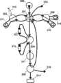
现在将参考图20和21来描述此类液相色谱系统的一个实施例,其中示出了具有与本发明相关的主要部件,而诸如附加的监视传感器、附加的阀、调整装置等的其它部件尽管对于此类系统也是重要的,但是为了清晰的原因而被省略了。An embodiment of such a liquid chromatography system will now be described with reference to FIGS. Although also important for such systems, it has been omitted for reasons of clarity.
因而,系统包括诸如泵302的主要流体源,泵302连接到根据如上所述的本发明的阀的流量分配阀301上。样品注入阀303包括附接的第一样品保持装置(在本文中以传统的毛细管回路311举例说明),该样品注入阀303连接到流量分配阀作为第一部件(参考上面给出的流量分配阀的描述)。多个色谱柱312、313(出于清晰原因,在该图中仅示出了两个此类色谱柱312、313,可选择的色谱柱的数量由第一选择阀304的容量决定)连接到其上的第一选择阀304被连接作为第二部件(参考以上流量分配阀的描述)。在该实施例中,第一选择阀304还串联地连接到样品监视装置上,在本文中用连接到色谱系统的控制单元(未显示)的UV传感器317和流路选择阀305举例说明,从而所有这三个部件均被称为第二部件。第二选择阀306具有一套可选择的样品保持装置,在本文中用毛细管回路315、316(即出于清晰原因,在图中仅显示了两个此类回路315、316,尽管可选择的回路的数量由选择阀的容量确定)距离说明,该第二选择阀306被连接到流量分配阀作为第三部件(参考上面给出的描述)。此外,用于收集小部分的分离样品的收集装置314(诸如传统的小部分收集器)连接到流路选择阀305上。部件用诸如PEEK毛细管的合适的管子互相连接,该PEEK毛细管具有适于在本文系统中使用的流率的内部直径。Thus, the system comprises a primary fluid source such as a
容易理解的是:带有其附接部件的注入阀303代表发明性的流量分配阀的以上描述的“第一部件”的示例。类似地,带有其附接的回路的第二选择阀306代表“第三部件”的一个示例,而第一选择阀304、附接到其上的柱312、UV传感器317和流路选择阀305一起代表发明性的流量分配阀的以上描述的“第二部件”的示例。It will be readily understood that the
样品注入阀303可以是传统的样品注入阀,诸如能够从GEHealthcare获得的INV-907型注入阀。
注入阀303允许若干操作位置。在第一“注入”位置,样品(诸如包含蛋白质和/或其它组分的生物制剂的一定量的液体)可以典型地用连接到注入阀303上的注射器而被传输至第一毛细管回路311。典型地,流在该位置从泵302经过注入阀303,并通过注入阀出口直接到达流量分配阀301。在第二“加载”位置,毛细管回路在泵302和注入阀出口之间被引入到流中。因而,样品在“加载”位置被压出毛细管回路311并被压入到流量分配阀301中。
第一选择阀304和第二选择阀306均可以是传统的多用途阀,诸如能够从Valco Instruments Co.Inc.获得的六端口ST阀。一个此类阀放置在柱/回路的前面,而另一个放在柱/回路的后面。Both the
流路选择阀305典型地是在本发明的现有技术中描述的该类型的传统的多用途阀。Flow
开始时,当注入阀位于其“注入”位置时,将用于净化的样品引入到注入阀303的毛细管回路311中。Initially, when the injection valve is in its "inject" position, the sample for purification is introduced into the
然后,色谱系统被设置成在图20中示出的第一操作模式,其特征在于流量分配阀301位于与显示在图17中的第一转子位置对应的第一位置。应当注意的是:出于清晰的原因,图20中阀301的入口/出口的相互位置没有像显示在图17中的实施例一样地画出。The chromatographic system is then set to the first mode of operation shown in FIG. 20 , characterized in that the
此外,在该系统的第一运行模式中,注入阀303位于其“加载”位置,第一选择阀304被设置成串联地连接其中一个柱312,而第二选择阀306被设置成串联地连接其中一个回路,例如回路315。Furthermore, in the first operating mode of the system, the
通过泵302,所使用的缓冲液体被压过流量分配阀301到达注入阀303,在此处该缓冲液体带着回路311的包含物(样品)离开注入阀303,到达流量分配阀301。样品通过流量分配阀301和第一选择阀304被注入色谱柱312中。样品根据所使用的色谱技术由色谱柱或者直接分离成组分,或者在随后的步骤中使用不同的缓冲液分离成组分。尽管本发明对于任何色谱技术是同样有用的,但是在该示出的描述中,假设分离发生在一个步骤中。By means of the
分离的组分用UV传感器307探测。UV信号由色谱系统的控制单元(未显示)处理,并且被用于控制流路选择阀305的位置。因而,可以将流路选择阀305设置在用小部分收集器314收集被探测的小部分样品的位置,或者经过流路选择阀305的液体可以被引向废弃出口319(或者任何可选的容器)。但是,被探测的小部分还可以由流路选择阀305引导返回到流量分配阀301。被探测的小部分由该阀被引导至第二选择阀306,从而被包含在选择回路315中。任何过量的液体均被传送回流量分配阀301,从而通过出口318从该系统排出。The separated components are detected with a
因而,如通过改变第二选择阀306的设置而选择的那样,若干不同的分离的小部分能够被隔离并且被选择性地放置在小部分收集器314中或者备选地被放置在不同的回路315、316中。这完全能够基于对来自UV探测器317的UV信号的分析而通过系统的控制单元自动地进行控制。Thus, as selected by changing the setting of the
如图21所示的色谱系统的第二运行模式的特征在于:流量分配阀301位于与显示在图19中的第二转子位置对应的第二位置。应当注意的是:对于图20,图21中阀301的入口/出口的相互位置没有像显示在图19中的实施例一样地画出。The second operating mode of the chromatography system as shown in FIG. 21 is characterized in that the
此外,在该系统的第二运行模式中,注入阀303位于其“加载”位置,第一选择阀304被设置成串联地连接到另一柱313上(然后另一柱在第一运行模式期间被连接),且第二选择阀306被设置成串联地连接其中一个回路,例如容纳所收集的小部分样品的回路315。Furthermore, in the second operating mode of the system, the
通过泵302现在将使用的缓冲液压过流量分配阀301到达第二选择阀306,以随缓冲液一起带动包含在选择的回路315中的小部分样品。流返回到流量分配阀301并从那里返回到第一选择阀304。The buffer hydraulic pressure that will now be used by the
在该第二运行模式中,与第一模式中不同的柱313现在可以串联地连接。因而,与第一运行模式中的原先的分离步骤相比,小部分样品现在可以用不同的分离技术进一步分离。In this second mode of operation,
与第一运行模式类似,分离的小部分由UV传感器317监视,并且用UV信号来控制流路选择阀305,以便将具有较低样品浓度的小部分和/或液体或者引导至小部分收集器314、任何出口319,或者返回至流量分配阀301。Similar to the first mode of operation, the separated fraction is monitored by the
按照这种方式被返回到流量分配阀301的小部分被进一步引向注入阀302,并且通过作用于该阀可包含在毛细管回路中,以在又一净化步骤(根据第一运行模式执行)中进一步处理。备选地,液体可通过注入阀302、流量分配阀301和出口318从该系统排出。The small portion returned in this way to the
考虑到选择阀(诸如第一选择阀304或者第二选择阀306)典型地包括内部旁通位置,应当理解的是:许多此类阀能够串联地进行连接。这允许形成系统,该系统可容纳期望数量的柱和/或回路,或者容纳实践中由背压或者由相互连接的毛细管造成的谱带增宽(bandbroadening)所限制数量的柱和/或回路。Considering that a selector valve, such as the
图22是此类系统的一个示例的示意性图解,用两个附加的回路选择阀306′、307和一个附加的柱选择阀304′扩展。Figure 22 is a schematic illustration of an example of such a system, extended with two additional
与显示在图20和21中的系统相比,第三选择阀306′被串联地放置在第二选择阀306之后。尽管为了清晰起见,这些阀306和306′被显示为各带有一个回路325,325’,但是应当理解的是:各阀能够具有如设计所需的多个回路,例如各具有五个回路。因而,在以上述的第一模式执行的分离期间,能够被存储的小部分的数量能够容易地扩展。In contrast to the systems shown in FIGS. 20 and 21 , the
类似地,第四选择阀307被串联地放置在注入阀303之后。尽管为了清晰起见,该阀307被显示为带有一个回路311’,但是应当理解的是其能够具有如设计所需要的多个回路,例如具有五个回路。因此,在起初或者在以上述的第二模式执行的分离期间,可被存储的小部分的数量能够容易地扩展。Similarly, a
最后,与显示在图20和21中的系统相比,第五选择阀304′可被串联地放置在第一选择阀304之后,这些阀均与附接的色谱柱322和322′相关联。尽管为了清晰起见,这些阀304、304′仅显示为各带有一个柱322、322′,但应当理解的是:各阀能够具有如设计所需要的多个柱,例如各具有五个色谱柱。因而,能够容易地扩展对于以上述第一或者第二模式执行的各种色谱技术的不同分离有用的色谱柱的数量。Finally, in contrast to the systems shown in Figures 20 and 21, a fifth selector valve 304' can be placed in series after the
因而,用根据本发明的流量分配阀,柔性自动的多步骤多维的色谱系统能够被设计成具有最小数量的必要的阀,以及具有短的相互连接的毛细管,从而降低由系统的流路造成的背压和谱带增宽。Thus, with the flow distribution valve according to the present invention, a flexible automatic multi-step multi-dimensional chromatographic system can be designed with a minimum number of necessary valves, and with short interconnected capillaries, thereby reducing the flow caused by the system flow path. Back pressure and band broadening.
Claims (5)
Translated fromChineseApplications Claiming Priority (4)
| Application Number | Priority Date | Filing Date | Title |
|---|---|---|---|
| SE0701221-4 | 2007-05-15 | ||
| SE07012214 | 2007-05-15 | ||
| SE0701221 | 2007-05-15 | ||
| PCT/SE2008/000288WO2008140374A1 (en) | 2007-05-15 | 2008-04-24 | Flow distributing valve |
Publications (2)
| Publication Number | Publication Date |
|---|---|
| CN101680861A CN101680861A (en) | 2010-03-24 |
| CN101680861Btrue CN101680861B (en) | 2012-10-10 |
Family
ID=40002446
Family Applications (1)
| Application Number | Title | Priority Date | Filing Date |
|---|---|---|---|
| CN200880016262XAExpired - Fee RelatedCN101680861B (en) | 2007-05-15 | 2008-04-24 | flow distribution valve |
Country Status (7)
| Country | Link |
|---|---|
| US (1) | US8225817B2 (en) |
| EP (1) | EP2147301A1 (en) |
| JP (1) | JP5377477B2 (en) |
| CN (1) | CN101680861B (en) |
| AU (1) | AU2008251098B2 (en) |
| CA (1) | CA2683944A1 (en) |
| WO (1) | WO2008140374A1 (en) |
Cited By (1)
| Publication number | Priority date | Publication date | Assignee | Title |
|---|---|---|---|---|
| TWI640710B (en)* | 2018-04-13 | 2018-11-11 | 蘇釗登 | Rotary self-holding fluid flux solenoid valve |
Families Citing this family (34)
| Publication number | Priority date | Publication date | Assignee | Title |
|---|---|---|---|---|
| JP4862947B2 (en)* | 2007-09-28 | 2012-01-25 | 株式会社島津製作所 | Sample introduction device |
| EP2196801B1 (en)* | 2008-12-11 | 2017-08-23 | Spark Holland B.V. | Method and apparatus for injecting a liquid sample in an HPLC analyzing device, and valve assembly for use therein. |
| WO2011001460A1 (en) | 2009-06-29 | 2011-01-06 | 株式会社島津製作所 | Flow path switching valve |
| US8656955B2 (en)* | 2010-05-20 | 2014-02-25 | Bio-Rad Laboratories, Inc. | Rotary column selector valve |
| JP5240245B2 (en)* | 2010-06-22 | 2013-07-17 | 東京エレクトロン株式会社 | Channel switching device, processing device, channel switching method and processing method, and storage medium |
| US9939415B2 (en) | 2011-01-12 | 2018-04-10 | Dionex Softron Gmbh | High-pressure control valve for high-performance liquid chromatography |
| DE102011000104B4 (en)* | 2011-01-12 | 2013-02-07 | Dionex Softron Gmbh | High pressure switching valve for high performance liquid chromatography |
| US8701711B2 (en) | 2011-06-13 | 2014-04-22 | Daniel Sharron | Continuously adjustable, multi-port selection, constant flow capability, externally-actuated rotary flow valve apparatus, system and method |
| US9304518B2 (en) | 2011-08-24 | 2016-04-05 | Bio-Rad Laboratories, Inc. | Modular automated chromatography system |
| US8960231B2 (en) | 2011-09-21 | 2015-02-24 | Neil Robert Picha | Multi-mode injection valve |
| US9200715B2 (en)* | 2011-11-11 | 2015-12-01 | Shimadzu Corporation | Passage-switching valve |
| US9182886B2 (en) | 2011-11-14 | 2015-11-10 | Bio-Rad Laboratories Inc. | Chromatography configuration interface |
| US8813785B2 (en)* | 2012-01-09 | 2014-08-26 | Promochrom Technologies Ltd. | Fluid selection valve |
| WO2013116285A1 (en) | 2012-02-01 | 2013-08-08 | Waters Technologies Corporation | Managing fluidic connections to microfluidic devices |
| JP6348493B2 (en) | 2012-08-22 | 2018-06-27 | ジーイー・ヘルスケア・バイオサイエンス・アクチボラグ | General purpose rotary valve |
| CN102836492A (en)* | 2012-09-20 | 2012-12-26 | 深圳市瑞沃德生命科技有限公司 | Zero safety protection device of anesthesia machine evaporator |
| CN103423484B (en)* | 2013-09-11 | 2015-08-26 | 青岛普仁仪器有限公司 | valve and chromatograph |
| CN103423483B (en)* | 2013-09-11 | 2015-08-26 | 青岛普仁仪器有限公司 | valve and chromatograph |
| EP3084420B1 (en)* | 2013-12-19 | 2018-10-17 | GE Healthcare Bio-Sciences AB | Chromatography system comprising a rotary valve and a feed recirculation flow path |
| JP6575946B2 (en)* | 2013-12-19 | 2019-09-18 | ジーイー・ヘルスケア・バイオサイエンス・アクチボラグ | Rotary valve and chromatography system |
| CN105980847B (en)* | 2014-02-14 | 2018-12-04 | 通用电气健康护理生物科学股份公司 | Automatic more purification system |
| US9752691B1 (en)* | 2014-07-03 | 2017-09-05 | Elemental Scientific, Inc. | Valve for controlled shuttle of liquid into microtiter plates and mixing |
| CN104330508B (en)* | 2014-10-31 | 2016-10-05 | 华南理工大学 | Intelligence automatic switchover multichannel gas chromatographic column attachment means |
| EP3234587B1 (en)* | 2014-12-15 | 2021-01-27 | Cytiva Sweden AB | Rotary valves and systems |
| CN104633182A (en)* | 2015-02-16 | 2015-05-20 | 苏州赛谱仪器有限公司 | Column-position valve |
| GB201505421D0 (en)* | 2015-03-30 | 2015-05-13 | Ge Healthcare Bio Sciences Ab | A rotary valve and a chromatography system |
| GB201517282D0 (en)* | 2015-09-30 | 2015-11-11 | Ge Healthcare Bio Sciences Ab | A chromatography system and a method therefor |
| AU2016426210A1 (en)* | 2016-10-12 | 2019-03-21 | Energy Harvest As | Rotary valve device and liquid lifting device comprising the same |
| US10527192B2 (en) | 2018-02-15 | 2020-01-07 | Talis Biomedical Corporation | Rotary valve |
| CN109541094B (en)* | 2018-12-11 | 2024-07-09 | 苏州英赛斯智能科技有限公司 | Selector valve and liquid chromatography device |
| JP7472156B2 (en)* | 2019-02-20 | 2024-04-22 | エフ ホフマン-ラ ロッシュ アクチェン ゲゼルシャフト | Valve for transferring at least one fluid |
| USD919833S1 (en) | 2019-03-06 | 2021-05-18 | Princeton Biochemicals, Inc | Micro valve for controlling path of fluids in miniaturized capillary connections |
| US11008627B2 (en) | 2019-08-15 | 2021-05-18 | Talis Biomedical Corporation | Diagnostic system |
| JP7334845B2 (en)* | 2020-02-21 | 2023-08-29 | 株式会社島津製作所 | liquid chromatograph |
Citations (5)
| Publication number | Priority date | Publication date | Assignee | Title |
|---|---|---|---|---|
| US4614204A (en)* | 1984-12-10 | 1986-09-30 | Uop Inc. | Rotary valve for interconnecting conduits in three groups |
| US4625569A (en)* | 1984-01-17 | 1986-12-02 | Toyo Soda Manufacturing Co., Ltd. | Liquid injection device |
| CN1149333A (en)* | 1994-05-24 | 1997-05-07 | 米利波尔公司 | Sanitizable slider diaphragm valve |
| US6012488A (en)* | 1998-09-17 | 2000-01-11 | Rheodyne, L.P. | Segmenting valve |
| US6672336B2 (en)* | 2001-11-28 | 2004-01-06 | Rheodyne, Lp | Dual random access, three-way rotary valve apparatus |
Family Cites Families (11)
| Publication number | Priority date | Publication date | Assignee | Title |
|---|---|---|---|---|
| GB1041514A (en)* | 1964-04-28 | 1966-09-07 | Distillers Co Yeast Ltd | Improvements in or relating to fluid sampling valves |
| US3504799A (en) | 1968-04-02 | 1970-04-07 | Beckman Instruments Inc | Sample injector |
| JPS57198475U (en)* | 1981-06-12 | 1982-12-16 | ||
| US4444066A (en)* | 1981-06-29 | 1984-04-24 | Beckman Instruments, Inc. | High pressure sample injector valve |
| US4506558A (en)* | 1983-03-03 | 1985-03-26 | Rheodyne Incorporated | Injector with minimal flow-interrupt transient |
| JPS60143279A (en)* | 1983-12-28 | 1985-07-29 | Shimadzu Corp | Selector valve of flow path |
| JPS6256858A (en)* | 1985-09-05 | 1987-03-12 | Toyo Soda Mfg Co Ltd | Flaw passage changing device |
| US5207109A (en)* | 1991-02-07 | 1993-05-04 | Rheodyne, Inc. | Internal-external sample injector |
| US5803117A (en)* | 1996-06-10 | 1998-09-08 | Rheodyne, L.P. | Multi-route full sweep selection valve |
| US6012448A (en)* | 1998-03-02 | 2000-01-11 | Arsenault; John W. | Fireplace draft regulator |
| US6155123A (en)* | 1998-04-17 | 2000-12-05 | Rheodyne, L.P. | Multivalving sample injection system |
- 2008
- 2008-04-24CNCN200880016262XApatent/CN101680861B/ennot_activeExpired - Fee Related
- 2008-04-24AUAU2008251098Apatent/AU2008251098B2/ennot_activeExpired - Fee Related
- 2008-04-24USUS12/597,826patent/US8225817B2/ennot_activeExpired - Fee Related
- 2008-04-24CACA 2683944patent/CA2683944A1/ennot_activeAbandoned
- 2008-04-24JPJP2010508334Apatent/JP5377477B2/ennot_activeExpired - Fee Related
- 2008-04-24EPEP20080741862patent/EP2147301A1/ennot_activeWithdrawn
- 2008-04-24WOPCT/SE2008/000288patent/WO2008140374A1/enactiveApplication Filing
Patent Citations (5)
| Publication number | Priority date | Publication date | Assignee | Title |
|---|---|---|---|---|
| US4625569A (en)* | 1984-01-17 | 1986-12-02 | Toyo Soda Manufacturing Co., Ltd. | Liquid injection device |
| US4614204A (en)* | 1984-12-10 | 1986-09-30 | Uop Inc. | Rotary valve for interconnecting conduits in three groups |
| CN1149333A (en)* | 1994-05-24 | 1997-05-07 | 米利波尔公司 | Sanitizable slider diaphragm valve |
| US6012488A (en)* | 1998-09-17 | 2000-01-11 | Rheodyne, L.P. | Segmenting valve |
| US6672336B2 (en)* | 2001-11-28 | 2004-01-06 | Rheodyne, Lp | Dual random access, three-way rotary valve apparatus |
Cited By (1)
| Publication number | Priority date | Publication date | Assignee | Title |
|---|---|---|---|---|
| TWI640710B (en)* | 2018-04-13 | 2018-11-11 | 蘇釗登 | Rotary self-holding fluid flux solenoid valve |
Also Published As
| Publication number | Publication date |
|---|---|
| JP2010526976A (en) | 2010-08-05 |
| WO2008140374A1 (en) | 2008-11-20 |
| CN101680861A (en) | 2010-03-24 |
| US8225817B2 (en) | 2012-07-24 |
| EP2147301A1 (en) | 2010-01-27 |
| AU2008251098A1 (en) | 2008-11-20 |
| US20100058841A1 (en) | 2010-03-11 |
| JP5377477B2 (en) | 2013-12-25 |
| CA2683944A1 (en) | 2008-11-20 |
| AU2008251098B2 (en) | 2013-11-21 |
Similar Documents
| Publication | Publication Date | Title |
|---|---|---|
| CN101680861B (en) | flow distribution valve | |
| JP6348493B2 (en) | General purpose rotary valve | |
| JP5270582B2 (en) | Rotating valve for sample injection | |
| JP6575946B2 (en) | Rotary valve and chromatography system | |
| JP5890865B2 (en) | Random access rotary valve | |
| JP6651238B2 (en) | Rotary valves and systems | |
| CN106461623B (en) | Methods and Valves in Continuous Chromatography Systems | |
| JPH05118452A (en) | Valve assembly for adjusting fluid flow and system | |
| WO2008140377A1 (en) | Random access rotary valve | |
| WO2010083147A1 (en) | Rotating valve |
Legal Events
| Date | Code | Title | Description |
|---|---|---|---|
| C06 | Publication | ||
| PB01 | Publication | ||
| C10 | Entry into substantive examination | ||
| SE01 | Entry into force of request for substantive examination | ||
| C14 | Grant of patent or utility model | ||
| GR01 | Patent grant | ||
| C17 | Cessation of patent right | ||
| CF01 | Termination of patent right due to non-payment of annual fee | Granted publication date:20121010 Termination date:20140424 |