CN101680747B - Moving body driving system, pattern forming apparatus, exposure apparatus and exposure method, and device manufacturing method - Google Patents
Moving body driving system, pattern forming apparatus, exposure apparatus and exposure method, and device manufacturing methodDownload PDFInfo
- Publication number
- CN101680747B CN101680747BCN200880019418XACN200880019418ACN101680747BCN 101680747 BCN101680747 BCN 101680747BCN 200880019418X ACN200880019418X ACN 200880019418XACN 200880019418 ACN200880019418 ACN 200880019418ACN 101680747 BCN101680747 BCN 101680747B
- Authority
- CN
- China
- Prior art keywords
- moving body
- scale
- mentioned
- predetermined plane
- heads
- Prior art date
- Legal status (The legal status is an assumption and is not a legal conclusion. Google has not performed a legal analysis and makes no representation as to the accuracy of the status listed.)
- Expired - Fee Related
Links
Images


Classifications
- G—PHYSICS
- G03—PHOTOGRAPHY; CINEMATOGRAPHY; ANALOGOUS TECHNIQUES USING WAVES OTHER THAN OPTICAL WAVES; ELECTROGRAPHY; HOLOGRAPHY
- G03F—PHOTOMECHANICAL PRODUCTION OF TEXTURED OR PATTERNED SURFACES, e.g. FOR PRINTING, FOR PROCESSING OF SEMICONDUCTOR DEVICES; MATERIALS THEREFOR; ORIGINALS THEREFOR; APPARATUS SPECIALLY ADAPTED THEREFOR
- G03F7/00—Photomechanical, e.g. photolithographic, production of textured or patterned surfaces, e.g. printing surfaces; Materials therefor, e.g. comprising photoresists; Apparatus specially adapted therefor
- G03F7/70—Microphotolithographic exposure; Apparatus therefor
- G03F7/708—Construction of apparatus, e.g. environment aspects, hygiene aspects or materials
- G03F7/7085—Detection arrangement, e.g. detectors of apparatus alignment possibly mounted on wafers, exposure dose, photo-cleaning flux, stray light, thermal load
- G—PHYSICS
- G03—PHOTOGRAPHY; CINEMATOGRAPHY; ANALOGOUS TECHNIQUES USING WAVES OTHER THAN OPTICAL WAVES; ELECTROGRAPHY; HOLOGRAPHY
- G03F—PHOTOMECHANICAL PRODUCTION OF TEXTURED OR PATTERNED SURFACES, e.g. FOR PRINTING, FOR PROCESSING OF SEMICONDUCTOR DEVICES; MATERIALS THEREFOR; ORIGINALS THEREFOR; APPARATUS SPECIALLY ADAPTED THEREFOR
- G03F7/00—Photomechanical, e.g. photolithographic, production of textured or patterned surfaces, e.g. printing surfaces; Materials therefor, e.g. comprising photoresists; Apparatus specially adapted therefor
- G03F7/70—Microphotolithographic exposure; Apparatus therefor
- G03F7/70691—Handling of masks or workpieces
- G03F7/70716—Stages
- G—PHYSICS
- G03—PHOTOGRAPHY; CINEMATOGRAPHY; ANALOGOUS TECHNIQUES USING WAVES OTHER THAN OPTICAL WAVES; ELECTROGRAPHY; HOLOGRAPHY
- G03F—PHOTOMECHANICAL PRODUCTION OF TEXTURED OR PATTERNED SURFACES, e.g. FOR PRINTING, FOR PROCESSING OF SEMICONDUCTOR DEVICES; MATERIALS THEREFOR; ORIGINALS THEREFOR; APPARATUS SPECIALLY ADAPTED THEREFOR
- G03F7/00—Photomechanical, e.g. photolithographic, production of textured or patterned surfaces, e.g. printing surfaces; Materials therefor, e.g. comprising photoresists; Apparatus specially adapted therefor
- G03F7/70—Microphotolithographic exposure; Apparatus therefor
- G03F7/70691—Handling of masks or workpieces
- G03F7/70758—Drive means, e.g. actuators, motors for long- or short-stroke modules or fine or coarse driving
- G—PHYSICS
- G03—PHOTOGRAPHY; CINEMATOGRAPHY; ANALOGOUS TECHNIQUES USING WAVES OTHER THAN OPTICAL WAVES; ELECTROGRAPHY; HOLOGRAPHY
- G03F—PHOTOMECHANICAL PRODUCTION OF TEXTURED OR PATTERNED SURFACES, e.g. FOR PRINTING, FOR PROCESSING OF SEMICONDUCTOR DEVICES; MATERIALS THEREFOR; ORIGINALS THEREFOR; APPARATUS SPECIALLY ADAPTED THEREFOR
- G03F7/00—Photomechanical, e.g. photolithographic, production of textured or patterned surfaces, e.g. printing surfaces; Materials therefor, e.g. comprising photoresists; Apparatus specially adapted therefor
- G03F7/70—Microphotolithographic exposure; Apparatus therefor
- G03F7/70691—Handling of masks or workpieces
- G03F7/70775—Position control, e.g. interferometers or encoders for determining the stage position
- G—PHYSICS
- G03—PHOTOGRAPHY; CINEMATOGRAPHY; ANALOGOUS TECHNIQUES USING WAVES OTHER THAN OPTICAL WAVES; ELECTROGRAPHY; HOLOGRAPHY
- G03F—PHOTOMECHANICAL PRODUCTION OF TEXTURED OR PATTERNED SURFACES, e.g. FOR PRINTING, FOR PROCESSING OF SEMICONDUCTOR DEVICES; MATERIALS THEREFOR; ORIGINALS THEREFOR; APPARATUS SPECIALLY ADAPTED THEREFOR
- G03F7/00—Photomechanical, e.g. photolithographic, production of textured or patterned surfaces, e.g. printing surfaces; Materials therefor, e.g. comprising photoresists; Apparatus specially adapted therefor
- G03F7/70—Microphotolithographic exposure; Apparatus therefor
- G03F7/708—Construction of apparatus, e.g. environment aspects, hygiene aspects or materials
- G03F7/70808—Construction details, e.g. housing, load-lock, seals or windows for passing light in or out of apparatus
- G03F7/70825—Mounting of individual elements, e.g. mounts, holders or supports
- G—PHYSICS
- G03—PHOTOGRAPHY; CINEMATOGRAPHY; ANALOGOUS TECHNIQUES USING WAVES OTHER THAN OPTICAL WAVES; ELECTROGRAPHY; HOLOGRAPHY
- G03F—PHOTOMECHANICAL PRODUCTION OF TEXTURED OR PATTERNED SURFACES, e.g. FOR PRINTING, FOR PROCESSING OF SEMICONDUCTOR DEVICES; MATERIALS THEREFOR; ORIGINALS THEREFOR; APPARATUS SPECIALLY ADAPTED THEREFOR
- G03F9/00—Registration or positioning of originals, masks, frames, photographic sheets or textured or patterned surfaces, e.g. automatically
- G03F9/70—Registration or positioning of originals, masks, frames, photographic sheets or textured or patterned surfaces, e.g. automatically for microlithography
- G03F9/7003—Alignment type or strategy, e.g. leveling, global alignment
- G03F9/7007—Alignment other than original with workpiece
- G03F9/7015—Reference, i.e. alignment of original or workpiece with respect to a reference not on the original or workpiece
- G—PHYSICS
- G03—PHOTOGRAPHY; CINEMATOGRAPHY; ANALOGOUS TECHNIQUES USING WAVES OTHER THAN OPTICAL WAVES; ELECTROGRAPHY; HOLOGRAPHY
- G03F—PHOTOMECHANICAL PRODUCTION OF TEXTURED OR PATTERNED SURFACES, e.g. FOR PRINTING, FOR PROCESSING OF SEMICONDUCTOR DEVICES; MATERIALS THEREFOR; ORIGINALS THEREFOR; APPARATUS SPECIALLY ADAPTED THEREFOR
- G03F9/00—Registration or positioning of originals, masks, frames, photographic sheets or textured or patterned surfaces, e.g. automatically
- G03F9/70—Registration or positioning of originals, masks, frames, photographic sheets or textured or patterned surfaces, e.g. automatically for microlithography
- G03F9/7049—Technique, e.g. interferometric
- G—PHYSICS
- G03—PHOTOGRAPHY; CINEMATOGRAPHY; ANALOGOUS TECHNIQUES USING WAVES OTHER THAN OPTICAL WAVES; ELECTROGRAPHY; HOLOGRAPHY
- G03F—PHOTOMECHANICAL PRODUCTION OF TEXTURED OR PATTERNED SURFACES, e.g. FOR PRINTING, FOR PROCESSING OF SEMICONDUCTOR DEVICES; MATERIALS THEREFOR; ORIGINALS THEREFOR; APPARATUS SPECIALLY ADAPTED THEREFOR
- G03F9/00—Registration or positioning of originals, masks, frames, photographic sheets or textured or patterned surfaces, e.g. automatically
- G03F9/70—Registration or positioning of originals, masks, frames, photographic sheets or textured or patterned surfaces, e.g. automatically for microlithography
- G03F9/7088—Alignment mark detection, e.g. TTR, TTL, off-axis detection, array detector, video detection
Landscapes
- Physics & Mathematics (AREA)
- General Physics & Mathematics (AREA)
- Engineering & Computer Science (AREA)
- Health & Medical Sciences (AREA)
- Environmental & Geological Engineering (AREA)
- Epidemiology (AREA)
- Public Health (AREA)
- Multimedia (AREA)
- Exposure And Positioning Against Photoresist Photosensitive Materials (AREA)
- Length Measuring Devices By Optical Means (AREA)
Abstract
Translated fromChineseDescription
Translated fromChinese【技术领域】【Technical field】
本发明是关于移动体驱动系统、图案形成装置、曝光装置及曝光方法、以及器件制造方法,更详言之,是关于使用编码器系统测量移动体的位置并实质沿既定平面驱动移动体的移动体驱动系统、具备该移动体驱动系统的图案形成装置、具备该移动体驱动系统的曝光装置及使用该移动体驱动系统的曝光方法、以及使用该曝光装置或该曝光方法的器件制造方法。The present invention relates to a moving body drive system, a pattern forming device, an exposure device and an exposure method, and a device manufacturing method. More specifically, it relates to using an encoder system to measure the position of a moving body and drive the moving body substantially along a predetermined plane. A body driving system, a pattern forming apparatus including the moving body driving system, an exposure apparatus including the moving body driving system, an exposure method using the moving body driving system, and a device manufacturing method using the exposure apparatus or the exposure method.
【背景技术】【Background technique】
以往,在制造半导体元件、液晶显示元件等的微型器件(电子器件)的光刻工序中,主要使用步进重复方式的投影曝光装置(所谓步进器)、或步进扫描方式的投影曝光装置(所谓扫描步进器(也称扫描仪))等。Conventionally, in the photolithography process for manufacturing microdevices (electronic devices) such as semiconductor elements and liquid crystal display elements, step-and-repeat method projection exposure devices (so-called steppers) or step-and-scan method projection exposure devices have been mainly used. (The so-called scanning stepper (also called scanner)) and so on.
此种曝光装置中,保持被曝光基板、例如晶片的载台的位置测量,一般是使用激光干涉仪进行的。然而,伴随着半导体元件的高集成化而使图案微细化,由此所要求的性能变得逐渐严格。例如,总重迭误差的容许值成为数nm级,伴随此,载台的位置控制误差的容许值也成为次毫微级以下。因此,也无法忽视因激光干涉仪的光束路上的环境气氛的温度变化及/或温度梯度的影响而产生的空气摇晃所导致的测量值短期变动。In such an exposure apparatus, the position measurement of a stage holding a substrate to be exposed, such as a wafer, is generally performed using a laser interferometer. However, as the pattern becomes finer along with the high integration of semiconductor elements, the required performance becomes increasingly strict. For example, the allowable value of the total overlay error is on the order of several nanometers, and accordingly, the allowable value of the position control error of the stage is also below the sub-nanometer order. Therefore, the short-term variation of the measurement value caused by the air shaking caused by the temperature change and/or the influence of the temperature gradient of the ambient atmosphere on the beam path of the laser interferometer cannot be ignored.
因此,最近,与干涉仪相比较而言不易受到空气摇晃影响的高分辨率的编码器备受关注,并提出有一种将该编码器使用于晶片载台等位置测量的曝光装置(参照例如专利文献1等)。该专利文献1所记载的曝光装置,在基板台上方,使用横跨包含基板台移动范围全区的宽广范围区域的栅板(GRID PLATE)。Therefore, recently, attention has been paid to a high-resolution encoder that is less susceptible to air vibrations compared with an interferometer, and an exposure device using the encoder for position measurement of a wafer stage or the like has been proposed (see, for example, Patent No. Literature 1, etc.). The exposure apparatus described in this Patent Document 1 uses a grid plate (GRID PLATE) spanning a wide area including the entire moving range of the substrate stage above the substrate stage.
然而,由于制造如专利文献1所揭示的大面积且高精度的栅板困难,因此需排列配置多个栅板。又,使用如专利文献1所揭示的大面积的栅板,不论在布局方面及精度方面均有其困难点,特别是从成本方面来看并非是实际可运用的方式。However, since it is difficult to manufacture a large-area and high-precision grid as disclosed in Patent Document 1, multiple grids need to be arranged in a row. In addition, using a large-area grid as disclosed in Patent Document 1 has difficulties in both layout and accuracy, and is not practical in terms of cost.
[专利文献1]美国专利申请公开第2006/0227309号说明书[Patent Document 1] Specification of US Patent Application Publication No. 2006/0227309
【发明内容】【Content of invention】
本发明有鉴于上述情况,从第1观点来看,提供一种第1移动体驱动系统,实质地沿既定平面驱动移动体,其特征在于,具备:第1标尺,以第1方向为长边方向配置在该移动体所对向的与该既定平面平行的第1面上,且形成有以该第1方向或与该第1方向垂直的第2方向为周期方向的第1光栅;第2标尺,以该第2方向为长边方向配置在该第1面,形成有周期方向与该第1光栅正交的第2光栅;测量系统,具有:第1读头群,包含以该第2方向的位置不同地配置在该移动体的与该既定平面实质平行的第2面且以该第1光栅的周期方向为测量方向的多个第1读头;以及第2读头群,包含以该第1方向的位置不同地配置在该移动体的该第2面且以该第2光栅的周期方向为测量方向的多个第2读头,该测量系统根据对向于该第1标尺的该第1读头的输出与对向于该第2标尺的该第2读头的输出,算出该移动体在包含该第1及第2方向的该既定平面内的至少两个自由度方向的位置信息;以及驱动系统,根据该测量系统所算出的位置信息,将该移动体沿该既定平面驱动。In view of the above circumstances, the present invention provides a first moving body driving system from a first point of view, which substantially drives the moving body along a predetermined plane, and is characterized in that it includes: a first scale, with the first direction as the long side The direction is arranged on the first surface parallel to the predetermined plane facing the moving body, and the first grating is formed with the first direction or the second direction perpendicular to the first direction as the periodic direction; the second The scale is disposed on the first surface with the second direction as the longitudinal direction, and a second grating whose periodic direction is perpendicular to the first grating is formed; the measurement system has: a first read head group, including the second grating A plurality of first read heads arranged in different positions in different directions on the second surface of the mobile body substantially parallel to the predetermined plane and taking the periodic direction of the first grating as the measurement direction; and the second read head group, including The positions in the first direction are differently arranged on the second surface of the mobile body and a plurality of second read heads with the periodic direction of the second grating as the measurement direction, the measurement system is based on the direction facing the first scale. The output of the first reading head and the output of the second reading head facing the second scale calculate the direction of at least two degrees of freedom of the moving body in the predetermined plane including the first and second directions. position information; and a driving system for driving the mobile body along the predetermined plane according to the position information calculated by the measurement system.
根据上述,由测量系统根据对向于第1标尺的第1读头的输出与对向于第2标尺的第2读头的输出,算出移动体在包含第1及第2方向的既定平面内的至少两个自由度方向的位置信息,并由驱动系统,根据该测量系统所算出的位置信息将移动体沿既定平面驱动。因此,不需要与移动体的移动范围全区对应地配置标尺(光栅),即可在移动体的移动范围全区中,根据测量系统的测量值,将移动体沿既定平面以良好精度驱动。According to the above, the measurement system calculates the position of the moving body in a predetermined plane including the first and second directions based on the output of the first reading head facing the first scale and the output of the second reading head facing the second scale. The position information in the direction of at least two degrees of freedom, and the driving system drives the moving body along a predetermined plane according to the position information calculated by the measurement system. Therefore, there is no need to arrange scales (gratings) corresponding to the entire moving range of the moving body, and the moving body can be driven with high precision along a predetermined plane in the entire moving range of the moving body based on the measured values of the measuring system.
本发明从第2观点来看,提供一种第2移动体驱动系统,实质地沿既定平面驱动移动体,其特征在于,具备:标尺,以第1方向为长边方向配置在该移动体所对向的与该既定平面平行的第1面上,且形成有以该第1方向及与该第1方向垂直的第2方向为周期方向的二维光栅;测量系统,具有以该第2方向的位置不同地配置在该移动体的与该既定平面实质平行的第2面且以该第1、第2方向为测量方向的多个二维读头,根据对向于该标尺的二维读头的输出,算出该移动体在包含该第1及第2方向的该既定平面内的至少两个自由度方向的位置信息;以及驱动系统,根据该测量系统所算出的位置信息将该移动体沿该既定平面驱动。From the second point of view, the present invention provides a second mobile body drive system, which drives the mobile body substantially along a predetermined plane, and is characterized in that it includes: a scale arranged on the mobile body with the first direction as the longitudinal direction. On the opposite first surface parallel to the predetermined plane, a two-dimensional grating with the first direction and the second direction perpendicular to the first direction as the periodic direction is formed; the measurement system has a A plurality of two-dimensional read heads arranged at different positions on the second surface of the mobile body substantially parallel to the predetermined plane and with the first and second directions as the measurement directions, according to the two-dimensional read heads facing the scale The output of the head calculates the position information of the moving body in at least two directions of freedom in the predetermined plane including the first and second directions; and the driving system calculates the position information of the moving body according to the position information calculated by the measurement system Drive along the given plane.
根据上述,由测量系统,根据对向于标尺的二维读头的输出,算出移动体在包含第1及第2方向的既定平面内的至少两个自由度方向的位置信息,并由驱动系统,根据该测量系统所算出的位置信息将移动体沿既定平面驱动。因此,不需要与移动体的移动范围全区对应地配置标尺(光栅),即可在移动体的移动范围全区中,根据测量系统的测量值,将移动体沿既定平面以良好精度驱动。According to the above, the measurement system calculates the position information of the moving body in at least two degrees of freedom directions in a predetermined plane including the first and second directions according to the output of the two-dimensional reading head facing the scale, and the driving system According to the position information calculated by the measurement system, the moving body is driven along a predetermined plane. Therefore, there is no need to arrange scales (gratings) corresponding to the entire moving range of the moving body, and the moving body can be driven with high precision along a predetermined plane in the entire moving range of the moving body based on the measured values of the measuring system.
本发明从第3观点来看,是一种在物体上形成图案的图案形成装置,其特征在于,具备:在该物体上生成图案的图案化装置;以及本发明的第1、第2移动体驱动系统的任一系统,为了对该物体形成图案而利用该移动体驱动系统对装载该物体的移动体进行驱动。From a third viewpoint, the present invention is a pattern forming device for forming a pattern on an object, characterized by comprising: a patterning device for forming a pattern on the object; and the first and second moving bodies of the present invention In any system of the driving system, the moving body on which the object is loaded is driven by the moving body driving system in order to form a pattern on the object.
根据上述,由图案化装置将图案生成于利用本发明的第1、第2移动体驱动系统的任一者以良好精度驱动的移动体上的物体,从而能以良好精度将图案形成于物体上。According to the above, the pattern can be formed on the object with good precision by generating the pattern on the object on the mobile body driven with good precision by either of the first and second mobile body driving systems of the present invention by the patterning device. .
本发明从第4观点来看,是一种第1曝光装置,由能量束的照射将图案形成于物体,其特征在于,具备:对该物体照射该能量束的图案化装置;以及本发明的第1、第2移动体驱动系统的任一者;为了使该能量束与该物体相对移动,利用该移动体驱动系统对装载该物体的移动体进行驱动。From a fourth viewpoint, the present invention is a first exposure device for forming a pattern on an object by irradiation of an energy beam, characterized by comprising: a patterning device for irradiating the object with the energy beam; and the present invention Either one of the first and second moving body driving systems; in order to relatively move the energy beam and the object, the moving body on which the object is loaded is driven by the moving body driving system.
根据上述,为了使从图案化装置照射于物体的能量束与该物体相对移动,利用本发明的第1、第2移动体驱动系统的任一者以良好精度驱动装载该物体的移动体。因此,能通过扫描曝光以良好精度将图案形成于物体上。As described above, in order to move the energy beam irradiated on the object from the patterning device relative to the object, the moving body on which the object is mounted is driven with high precision by either the first or second moving body drive systems of the present invention. Therefore, a pattern can be formed on an object with good precision by scanning exposure.
本发明从第5观点来看,是一种第2曝光装置,用能量束使物体曝光,其特征在于,具备:移动体,能保持该物体沿既定平面移动;标尺,与该既定平面实质平行且以第1方向为长边方向所配置;以及编码器系统,具有设于该移动体、在该既定平面内关于与该第1方向正交的第2方向位置不同的多个读头,至少在该物体的曝光时,由与该标尺对向的该多个读头的至少一个读头测量该移动体的位置信息。From the fifth point of view, the present invention is a second exposure device for exposing an object with an energy beam, characterized by comprising: a moving body capable of keeping the object moving along a predetermined plane; a scale substantially parallel to the predetermined plane And the first direction is arranged as the longitudinal direction; and the encoder system has a plurality of read heads that are arranged on the moving body and have different positions in the predetermined plane with respect to the second direction orthogonal to the first direction, at least When the object is exposed, at least one of the plurality of read heads facing the scale measures the position information of the moving body.
根据上述,编码器系统的多个读头被设于移动体,至少在物体的曝光时,由与标尺(与既定平面实质平行且以第1方向为长边方向所配置)对向的该多个读头的至少一个读头测量该移动体的位置信息。According to the above, the plurality of heads of the encoder system are provided on the moving body, at least when the object is exposed, the plurality of heads facing the scale (arranged substantially parallel to the predetermined plane and with the first direction as the longitudinal direction) At least one read head of the read heads measures the position information of the moving body.
本发明从第6观点来看,是一种第1器件制造方法,其包含:使用本发明的第1、第2曝光装置的任一者使物体曝光的动作;以及使该已曝光的物体显影的动作。From the sixth viewpoint, the present invention is a first device manufacturing method comprising: exposing an object using any one of the first and second exposure apparatuses of the present invention; and developing the exposed object. Actions.
本发明从第7观点来看,是一种第1曝光方法,用能量束使物体曝光,其特征在于,包含:用移动体保持该物体的动作;以及由本发明的第1、第2移动体驱动系统的任一者驱动该移动体,用该能量束使该物体曝光的动作。From the seventh point of view, the present invention is a first exposure method for exposing an object with an energy beam, which is characterized in that it includes: holding the object with a moving body; and using the first and second moving bodies of the present invention Any one of the drive systems drives the moving body and exposes the object with the energy beam.
根据上述,由于保持物体的移动体,通过本发明的第1、第2移动体驱动系统的任一者以良好精度驱动,因此能对该物体良好地曝光。As described above, since the moving body holding the object is driven with high precision by either the first or second moving body drive systems of the present invention, the object can be exposed well.
本发明从第8观点来看,是一种第2曝光方法,用能量束使实质地沿既定平面移动的移动体所保持的物体曝光,其特征在于:在该移动体所对向的与该既定平面平行的第1面上,配置以第1方向为长边方向、且形成有以该第1方向或与该第1方向垂直的第2方向为周期方向的第1光栅的第1标尺,以及以该第2方向为长边方向、且形成有周期方向与该第1光栅正交的第2光栅的第2标尺;且包含:测量步骤,根据包含多个第1读头的第1读头群与包含多个第2读头的第2读头群中、对向于该第1标尺的该第1读头的输出与对向于该第2标尺的该第2读头的输出,算出该移动体在包含该第1及第2方向的该既定平面内的至少两个自由度方向的位置信息,该多个第1读头在该移动体的与该既定平面实质平行的第2面配置成该第2方向的位置不同且以该第1光栅的周期方向为测量方向,多个第2读头在该移动体的该第2面配置成该第1方向的位置不同且以该第2光栅的周期方向为测量方向;以及驱动步骤,根据该测量步骤所算出的位置信息,将该移动体沿该既定平面驱动。From the eighth point of view, the present invention is a second exposure method, which uses energy beams to expose an object held by a moving body that substantially moves along a predetermined plane, and is characterized in that: On the first surface parallel to the predetermined plane, a first scale is arranged with the first direction as the longitudinal direction and a first grating whose periodic direction is formed in the first direction or a second direction perpendicular to the first direction, And take the second direction as the long-side direction and form a second scale with a second grating whose periodic direction is orthogonal to the first grating; In the head group and the second head group including a plurality of second heads, the output of the first head facing the first scale and the output of the second head facing the second scale, Calculate the position information of the moving body in at least two degrees of freedom directions in the predetermined plane including the first and second directions, and the plurality of first reading heads are located on the second direction of the moving body substantially parallel to the predetermined plane. The surface is arranged so that the positions in the second direction are different and the period direction of the first grating is used as the measurement direction, and a plurality of second read heads are arranged on the second surface of the moving body so that the positions in the first direction are different and the measurement direction is set in the direction of the period of the first grating. The cycle direction of the second grating is the measurement direction; and the driving step is to drive the moving body along the predetermined plane based on the position information calculated in the measurement step.
根据上述,根据对向于第1标尺的第1读头的输出与对向于第2标尺的第2读头的输出,算出移动体在包含第1及第2方向的既定平面内的至少两个自由度方向的位置信息,并根据该测量系统所算出的位置信息将移动体沿既定平面驱动。因此,不需要与移动体的移动范围全区对应地配置标尺(光栅),即可在移动体的移动范围全区中,根据测量系统的测量值,将移动体沿既定平面以良好精度驱动,进而能对移动体所保持的物体进行高精度的曝光。According to the above, based on the output of the first reading head facing the first scale and the output of the second reading head facing the second scale, at least two positions of the moving body in a predetermined plane including the first and second directions are calculated. According to the position information calculated by the measurement system, the moving body is driven along a predetermined plane. Therefore, there is no need to arrange scales (gratings) corresponding to the entire moving range of the moving body, and the moving body can be driven with good precision along a predetermined plane in the entire moving range of the moving body based on the measured values of the measuring system. Furthermore, high-precision exposure can be performed on an object held by the moving body.
本发明从第9观点来看,是一种第3曝光方法,用能量束使实质地沿既定平面移动的移动体所保持的物体曝光,其特征在于:在该移动体所对向的与该既定平面平行的第1面上,配置以第1方向为长边方向、且形成有以该第1方向及与该第1方向垂直的第2方向为周期方向的二维光栅的标尺,该方法包括:测量步骤,根据以该第2方向的位置不同地配置在该移动体的与该既定平面实质平行的第2面且以该第1、第2方向为测量方向的多个二维读头中、对向于该标尺的二维读头的输出,算出该移动体在包含该第1及第2方向的该既定平面内的至少两个自由度方向的位置信息;以及驱动步骤,根据该测量步骤所算出的位置信息,将该移动体沿该既定平面驱动。From the ninth point of view, the present invention is a third exposure method, which uses energy beams to expose an object held by a moving body that substantially moves along a predetermined plane, and is characterized in that: On the first surface parallel to the predetermined plane, a scale with a two-dimensional grating having the first direction as the long side direction and a two-dimensional grating with the first direction and the second direction perpendicular to the first direction as the periodic direction is arranged, the method Including: the measuring step, according to the position of the second direction, a plurality of two-dimensional reading heads are arranged on the second surface of the mobile body substantially parallel to the predetermined plane and the first and second directions are the measurement directions. Among them, calculating the position information of the moving body in at least two degrees of freedom directions in the predetermined plane including the first and second directions for the output of the two-dimensional reading head facing the scale; and the driving step, according to the The position information calculated in the measuring step drives the moving body along the predetermined plane.
根据上述,根据对向于标尺的二维读头的输出,算出移动体在包含第1及第2方向的既定平面内的至少两个自由度方向的位置信息,并根据该测量系统所算出的位置信息将移动体沿既定平面驱动。因此,不需要与移动体的移动范围全区对应地配置标尺(光栅),即可在移动体的移动范围全区中,根据测量系统的测量值,将移动体沿既定平面以良好精度驱动,进而能对移动体所保持的物体进行高精度的曝光。According to the above, according to the output of the two-dimensional reading head facing the scale, the position information of the moving body in at least two degrees of freedom directions in the predetermined plane including the first and second directions is calculated, and the position information calculated by the measurement system is The position information drives the moving body along a predetermined plane. Therefore, there is no need to arrange scales (gratings) corresponding to the entire moving range of the moving body, and the moving body can be driven with good precision along a predetermined plane in the entire moving range of the moving body based on the measured values of the measuring system. Furthermore, high-precision exposure can be performed on an object held by the moving body.
本发明从第10观点来看,是一种第4曝光方法,用能量束使能沿既定平面移动的移动体所保持的物体曝光,其特征在于:使用具有设于该移动体、在该既定平面内关于与该第1方向正交的第2方向位置不同的多个读头的编码器系统,由与该既定平面实质平行且与以第1方向为长边方向配置的标尺对向的该多个读头中的至少一个读头,至少在该物体的曝光时测量该移动体的位置信息。From the tenth point of view, the present invention is a fourth exposure method, which uses energy beams to expose an object held by a moving body that can move along a predetermined plane, and is characterized in that: In the encoder system of a plurality of read heads with different positions in the second direction orthogonal to the first direction in the plane, the encoder system is substantially parallel to the predetermined plane and faces the scale arranged with the first direction as the longitudinal direction. At least one of the plurality of read heads measures position information of the moving body at least during exposure of the object.
根据上述,使用编码器(其在第2方向位置不同的多个读头被设于移动体),至少在物体的曝光时,由与标尺(与既定平面实质平行且以第1方向为长边方向所配置)对向的该多个读头的至少一个读头测量该移动体的位置信息。According to the above, using an encoder (a plurality of read heads with different positions in the second direction are provided on the moving body), at least when exposing the object, the scale (substantially parallel to the predetermined plane and with the first direction as the long side) At least one read head of the plurality of read heads facing the direction configured) measures the position information of the moving body.
本发明从第11观点来看,是一种第2器件制造方法,其包含:使用本发明的第2、第3、以及第4曝光方法中的任一者使物体曝光的动作;以及使该已曝光的物体显影的动作。From the eleventh viewpoint, the present invention is a second device manufacturing method comprising: exposing an object using any one of the second, third, and fourth exposure methods of the present invention; and exposing the The act of developing an exposed object.
【附图说明】【Description of drawings】
图1是显示一实施形态的曝光装置的概略构成图。FIG. 1 is a schematic configuration diagram showing an exposure apparatus according to an embodiment.
图2是放大显示图1的载台装置附近的构成部分的图。FIG. 2 is an enlarged view showing components in the vicinity of the stage device in FIG. 1 .
图3是将晶片载台与用以测量该晶片载台的位置信息的编码器及干涉仪一起显示的俯视图。3 is a top view showing a wafer stage together with an encoder and an interferometer for measuring position information of the wafer stage.
图4是将一实施形态的曝光装置的载台控制的相关联控制系统省略一部分后显示的方块图。FIG. 4 is a block diagram showing a part of the control system related to stage control of the exposure apparatus according to the embodiment, with a part omitted.
图5(A)是显示晶片的中央附近成为投影单元的正下方的位置处有一晶片载台的状态的图,图5(B)是显示晶片中心与外周的中间附近成为投影单元的正下方的位置处有一晶片载台的状态的图。5(A) is a diagram showing a state where a wafer stage is located at a position directly below the projection unit near the center of the wafer, and FIG. 5(B) is a diagram showing a state where the vicinity of the middle of the wafer center and the outer periphery is directly below the projection unit. There is a picture of the state of the wafer stage at the position.
图6(A)是显示晶片载台位于晶片的+Y侧边缘附近成为投影单元PU的正下方的位置的状态的图,图6(B)是显示晶片载台位于从晶片中心观看时相对X轴及Y轴成45°的方向的边缘附近成为投影单元PU的正下方的位置的状态的图。FIG. 6(A) is a diagram showing a state where the wafer stage is located near the +Y side edge of the wafer at a position directly below the projection unit PU, and FIG. A diagram showing a state in which the vicinity of the edge in the direction of 45° between the Y-axis and the Y-axis is located directly below the projection unit PU.
图7是显示晶片载台位于晶片的+X侧边缘附近成为投影单元PU的正下方的位置的状态的图。FIG. 7 is a diagram showing a state where the wafer stage is located in the vicinity of the +X side edge of the wafer at a position directly below the projection unit PU.
图8是显示其它实施形态的晶片载台用的编码器系统的图。Fig. 8 is a diagram showing an encoder system for a wafer stage according to another embodiment.
图9是显示其它实施形态的晶片载台用的编码器系统的图。Fig. 9 is a diagram showing an encoder system for a wafer stage according to another embodiment.
【实施方式】【Implementation】
以下,根据图1~图7说明本发明的一实施形态。Hereinafter, an embodiment of the present invention will be described with reference to FIGS. 1 to 7 .
图1显示一实施形态的曝光装置100的概略构成。曝光装置100是步进扫描方式的缩小投影曝光装置、也即所谓扫描机。如后述般,在本实施形态中,设有投影光学系统PL,以下的说明中,将与此投影光学系统PL的光轴AX平行的方向设为Z轴方向、将在与该Z轴方向正交的面内标线片与晶片相对扫描的方向设为Y轴方向、将与Z轴及Y轴正交的方向设为X轴方向,且将绕X轴、Y轴、及Z轴的旋转(倾斜)方向分别设为θx、θy、及θz方向。FIG. 1 shows a schematic configuration of an exposure apparatus 100 according to an embodiment. The exposure apparatus 100 is a step-and-scan reduction projection exposure apparatus, that is, a so-called scanner. As will be described later, in this embodiment, a projection optical system PL is provided. In the following description, a direction parallel to the optical axis AX of this projection optical system PL is referred to as the Z-axis direction, and a direction parallel to the Z-axis direction is defined as The direction in which the orthogonal in-plane reticle scans relative to the wafer is defined as the Y-axis direction, the direction perpendicular to the Z-axis and the Y-axis is defined as the X-axis direction, and the direction around the X-axis, Y-axis, and Z-axis is The rotation (tilt) directions are defined as θx, θy, and θz directions, respectively.
曝光装置100包含:照明系统10、保持标线片R的标线片载台RST、投影单元PU、包含载置晶片W的晶片载台WST的晶片载台装置12、以及它们的控制系统等。Exposure apparatus 100 includes
照明系统10,例如美国专利申请公开第2003/0025890号说明书等所揭示,包含照明光学系统,该照明光学系统具备:光源、具有包含光学积分器等的照度均一化光学系统、以及标线片遮帘等(均未图标)。照明系统10由照明光(曝光用光)IL,以大致均一的照度来照明被标线片遮帘(屏蔽系统)规定的标线片R上的狭缝状照明区域IAR。此处,作为一例,使用ArF准分子激光光束(波长193nm)来作为照明光IL。The
在标线片载台RST上例如通过真空吸附固定有标线片R,该标线片R在其图案面(图1的下面)上形成有电路图案等。标线片载台RST能由包含例如线性马达等的标线片载台驱动系统11在XY平面内微幅驱动,且能以既定的扫描速度驱动于扫描方向(图1的图面内左右方向即Y轴方向)。On the reticle stage RST, for example, a reticle R on which a circuit pattern or the like is formed on a pattern surface (lower surface in FIG. 1 ) is fixed by vacuum suction. The reticle stage RST can be slightly driven in the XY plane by the reticle
标线片载台RST在XY平面(移动面)内的位置信息(包含θz方向的旋转信息),是由图1所示的标线片激光干涉仪(以下称为「标线片干涉仪」)16,通过移动镜15(实际上是设有:具有与Y轴方向正交的反射面的Y移动镜(或后向反射器)、以及具有与X轴方向正交的反射面的X移动镜),以固定于镜筒40(构成投影单元PU)的侧面的固定镜14(实际上为X固定镜、Y固定镜的各固定镜)为基准,例如以0.25nm左右的分辨率,总是被检测出。The position information (including the rotation information in the θz direction) of the reticle stage RST in the XY plane (moving plane) is determined by the reticle laser interferometer (hereinafter referred to as "reticle interferometer") shown in Figure 1. ) 16, through the moving mirror 15 (in fact, it is provided with: a Y moving mirror (or retroreflector) with a reflective surface orthogonal to the Y-axis direction, and an X movement with a reflective surface orthogonal to the X-axis direction Mirror) is based on the fixed mirror 14 (actually each fixed mirror of X fixed mirror and Y fixed mirror) fixed to the side of the lens barrel 40 (constituting the projection unit PU), for example, with a resolution of about 0.25 nm, the total is detected.
投影单元PU,是在标线片载台RST的图1下方,通过突缘FLG保持于未图示主体的一部分(镜筒固定座)。投影单元PU包含:镜筒40,为圆筒状且在其外周部的下端部附近设有突缘FLG;以及投影光学系统PL,由保持于该镜筒40内的多个光学元件构成。作为投影光学系统PL,例如使用沿与Z轴方向平行的光轴AX排列的多个光学元件(透镜元件)所构成的折射光学系统。投影光学系统PL,例如是两侧远心且具有既定(规定)投影倍率(例如1/4倍或1/5倍)。因此,当用来自照明系统10的照明光IL来照明照明区域IAR时,利用通过图案面大致配置成与投影光学系统PL的第1面(物体面)一致的标线片R的照明光IL,使其照明区域IAR内的标线片R的电路图案缩小像(电路图案的一部分缩小像)经由投影光学系统PL形成于一区域(曝光区域),该区域是配置于投影光学系统PL的第2面(像面)侧的、表面涂布有抗蚀剂(感应剂)的晶片W上的与前述照明区域IAR共轭的区域。接着,通过标线片载台RST与晶片载台WST的同步驱动,使标线片R相对于照明区域IAR(照明光IL)在扫描方向(Y轴方向)上进行相对移动,且使晶片W相对于曝光区域(照明光IL)在扫描方向(Y轴方向)上进行相对移动,由此对晶片W上的一个照射(shot)区域(区划区域)进行扫描曝光,将标线片R的图案转印于该照射区域。即,本实施形态中,利用照明系统10、标线片R及投影光学系统PL将图案生成于晶片W上,利用照明光IL对晶片W上的感应层(抗蚀剂层)的曝光将其图案形成于晶片W上。The projection unit PU is held by a part (barrel holder) of the main body (not shown) through the flange FLG on the lower side of the reticle stage RST in FIG. 1 . Projection unit PU includes: lens barrel 40 having a cylindrical shape and flange FLG provided near the lower end portion of the outer peripheral portion; and projection optical system PL composed of a plurality of optical elements held in lens barrel 40 . As projection optical system PL, for example, a refractive optical system including a plurality of optical elements (lens elements) arranged along optical axis AX parallel to the Z-axis direction is used. Projection optical system PL is, for example, bilaterally telecentric and has a predetermined (predetermined) projection magnification (for example, 1/4 or 1/5). Therefore, when the illumination area IAR is illuminated with the illumination light IL from the
晶片载台装置12具备:利用设置于地面F上的底板BS上所配置的多个(例如三个或四个)防振机构(省略图示)大致支撑成水平的载台底座71;配置于该载台底座71上方的晶片载台WST;驱动该晶片载台WST的晶片载台驱动系统27(图1中未图示、参照图4)等。The
载台底座71由具有平板状外形的构件构成,其上表面的平坦度作成非常高,成为晶片载台WST的移动时的导引面。在载台底座71内部收容有线圈单元,该线圈单元包含以XY二维方向为行方向、列方向配置成矩阵状的多个线圈。
晶片载台WST如图2所示,具有载台本体30与其上部的晶片台WTB,在载台本体30的底部,设有与上述线圈单元一起构成磁浮型平面马达的具有多个磁石的磁石单元31。本实施形态中,线圈单元不仅具有X轴方向驱动线圈及Y轴方向驱动线圈,还具有Z轴方向驱动线圈,由这些线圈单元与上述磁石单元,构成将晶片载台WST驱动于X轴方向、Y轴方向、Z轴方向、θx方向、θy方向、以及θz方向的六个自由度方向的电磁力驱动方式(劳伦兹力驱动方式)的动磁型平面马达(二维线性致动器)。包含上述平面马达在内而构成晶片载台驱动系统27。本实施形态中,供应至构成线圈单元的各线圈的电流的大小及方向是由主控制装置2θ控制的。Wafer stage WST, as shown in FIG. 2, has a
此外,晶片载台WST也可采用具备载台本体(利用例如线性马达或平面马达等在XY平面内被驱动)与晶片台(在该载台本体上利用音圈马达等微幅驱动于至少Z轴方向、θx方向、以及θy方向的三个自由度方向)的构造。此种情形下,可使用例如美国专利第5,196,745号说明书等揭示的由劳伦兹电磁力驱动的平面马达等。此外,不限于劳伦兹电磁力驱动方式,也可使用可变磁气电阻驱动方式的平面马达。In addition, the wafer stage WST can also be equipped with a stage body (driven in the XY plane by, for example, a linear motor or a planar motor) and a wafer stage (on the stage body, it is slightly driven by a voice coil motor or the like to at least Z axis direction, θx direction, and θy direction (three degrees of freedom directions) structure. In this case, for example, a planar motor driven by Lorentzian electromagnetic force disclosed in US Pat. No. 5,196,745 or the like can be used. In addition, not limited to the Lorentz electromagnetic force driving method, a planar motor of the variable magnetoresistive driving method may be used.
在晶片台WTB上,通过未图示晶片保持具来载置晶片W,利用例如真空吸附(或静电吸附)等进行固定。On wafer table WTB, wafer W is placed on a wafer holder (not shown), and fixed by, for example, vacuum suction (or electrostatic suction).
又,晶片载台WST在XY平面内的位置信息,可利用图1所示的包含标尺构件46B、46C、46D等的编码器系统50(参照图4)与晶片激光干涉仪系统(以下简称为「干涉仪系统」)18分别测量。以下,详述晶片载台WST用编码器系统50及干涉仪系统18的构成等。此外,标尺构件也可称为栅板、光栅构件、或基准构件等。Also, the position information of the wafer stage WST in the XY plane can be obtained by using the encoder system 50 (refer to FIG. 4 ) including the
在晶片台WTB(晶片载台WST)的上面,如图3的俯视图所示,包围晶片W设有多个(此处为各10个)X读头(以下适当简称为读头(head))661~6610及Y读头(以下适当简称为读头)641~6410。详言之,在晶片台WTB上面的+Y侧端部、以及-Y侧端部,沿X轴方向以既定间隔配置有X读头661、662、...665、以及666、667、...6610。又,在晶片台WTB上面的+X侧端部、以及-X侧端部,沿Y轴方向以既定间隔配置有Y读头641、642、...645、以及646、647、...6410。作为Y读头641~6410、以及X读头661~6610的各读头,使用与例如美国专利第7,238,931号说明书或国际公开第2007/083758号小册子(对应美国专利申请公开第2007/0288121号说明书)等所揭示的读头(编码器)相同的构成的读头。此外,以下将Y读头641~6410及X读头661~6610还分别记述为Y读头64及X读头66。On the upper surface of wafer table WTB (wafer stage WST), as shown in the plan view of FIG. 661 to 6610 and the Y head (hereinafter referred to as the head as appropriate) 641 to 6410 . Specifically, X heads 661, 662 ,. , 667 , ... 6610 . Also, Y heads 641 , 642 , ... 645 , and 646 , 64 are arranged at predetermined intervals along the Y-axis direction at the +X side end and -X side end of the upper surface of wafer table WTB.7 ,... 6410 . As each of the Y heads 641 to 6410 and the X heads 661 to 6610 , for example, US Pat. 2007/0288121 specification) and the like disclosed in the reading head (encoder) of the same configuration. In addition, below, the Y heads 641 to 6410 and the X heads 661 to 6610 are also described as the Y head 64 and the X head 66 , respectively.
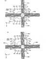
另一方面,综合图1及图3可知,以从四方包围投影单元PU最下端部周围的状态,配置有四个标尺构件46A~46D。这些标尺构件46A~46D,虽在图1因为了避免附图过于复杂而予以省略图示,但实际上例如通过支撑构件以悬吊状态固定于镜筒固定座。On the other hand, as can be seen from a combination of FIGS. 1 and 3 , four
标尺构件46A,46C分别在投影单元PU的-X侧、+X侧,以X轴方向为长边方向且相对投影光学系统PL的光轴AX对称地进行配置。标尺构件46B,46D分别在投影单元PU的+Y侧、-Y侧,以Y轴方向为长边方向且相对投影光学系统PL的光轴AX对称地进行配置。
标尺构件46A~46由同一材料(例如陶瓷或低热膨胀的玻璃等)构成,在其表面(图1的下面,即-Z侧的面)形成有以垂直于长边方向的方向为周期方向的同一反射型绕射光栅。此绕射光栅,例如以138nm~4μm间的间距、例如1μm间距刻划作成。此外,图3中为了图示方便,光栅的间距比实际间距显示成非常宽。又,在标尺构件46A~46D表面(光栅面),也可设置对来自上述读头的测量光束实质上透明的覆盖(cover)构件(例如玻璃板等)。The
标尺构件46A,46C,由于绕射光栅是以Y轴方向为周期方向,因此用于测量晶片载台WST在Y轴方向的位置。又,标尺构件46B及46D,由于绕射光栅是以X轴方向为周期方向,因此用于测量晶片载台WST在X轴方向的位置。
本实施形态中,以相邻的两个X读头66能同时对向于所对应的标尺构件(绕射光栅)的间隔,即以与在标尺构件46B,46D的长边方向所正交的方向(绕射光栅的排列方向)上的绕射光栅的长度相同程度以下的间隔,将X读头661、662、...665、以及666、667、...6610配置于晶片台WTB上。In the present embodiment, two adjacent X reading heads 66 can face the interval of the corresponding scale member (diffraction grating) at the same time, that is, with the length perpendicular to the longitudinal direction of the
同样地,以相邻的两个Y读头64能同时对向于所对应的标尺构件(绕射光栅)的间隔,即以与在标尺构件46A,46C的长边方向所正交的方向(绕射光栅的排列方向)上的绕射光栅的长度相同程度以下的间隔,将Y读头641、642、...645、以及646、647、...6410配置于晶片台WTB上。Similarly, with the interval that two adjacent Y read heads 64 can face the corresponding scale member (diffraction grating) at the same time, that is, with the direction perpendicular to the long side direction of the
Y读头641、642、...645、以及646、647、...6410的各读头,与标尺构件46C、46A的任一者对向,构成用以测量晶片载台WST的Y位置的多眼、更正确而言为5眼的Y线性编码器。又,X读头661、662、...665、以及666、667、...6610的各读头,与标尺构件46B、46D的任一者对向,构成用以测量晶片载台WST的X位置的多眼、更正确而言为5眼的X线性编码器。Each of the Y read heads 641 , 642 , ... 645 , and 646 , 647 , ... 6410 faces any one of the
在晶片W位于投影光学系统PL(投影单元PU)下方的、曝光时的晶片载台WST的移动范围内,Y读头64i(i=1~5的任一者),64j(j =i+5)分别对向于标尺构件46C,46A,且X读头66p(p=1~5的任一者),66q(q=p+5)分别对向于标尺构件46B,46D。即,分别对向于标尺构件46C,46A的Y读头64i,64j所构成的一对Y线性编码器50C,50A(参照图4)与分别对向于标尺构件46B,46D的X读头66p,66q所构成的一对X线性编码器50B,50D(参照图4)的合计四个编码器的测量值被供应至主控制装置20。包含一对Y线性编码器50C,50A与一对X线性编码器50B,50D而构成图4的编码器系统50。Within the moving range of wafer stage WST during exposure where wafer W is positioned below projection optical system PL (projection unit PU), Y heads 64i (any one of i=1 to 5), 64j (j= i+5) are respectively opposite to the
又,干涉仪系统18如图2所示,通过将测距光束照射于形成在晶片台WTB端面的反射面及固定在载台本体30的移动镜43,以例如0.25nm左右的分辨率总是检测晶片载台WST的位置信息。干涉仪系统18的至少一部分(例如除了光源以外的光学单元)以悬吊状态固定于镜筒固定座。In addition, the
在晶片载台WST,虽实际如图3所示形成有与作为扫描方向的Y轴方向正交的反射面17Y、以及与作为非扫描方向的X轴方向正交的反射面17X,但图1仅将这些代表性地显示为反射面17。In wafer stage WST, although actually as shown in FIG. These are only representatively shown as reflective surfaces 17 .
干涉仪系统18如图3所示,包含晶片Y干涉仪18Y、两个晶片X干涉仪18X1及18X2、以及一对Z干涉仪18Z1,18Z2的五个干涉仪。作为这些五个干涉仪18Y、18X1、18X2、18Z1、18Z2用如下干涉仪,即,使用利用了塞曼效应的双频激光的迈克尔逊型外差激光干涉仪。其中,作为晶片Y干涉仪18Y,如图3所示,使用具有多个测距轴(包含两个测距轴,该两个测距轴相对于通过投影光学系统PL的光轴AX(与前述照明区域IAR共轭的曝光区域的中心)及后述的对准系统ALG的检测中心且与Y轴平行的轴(基准轴)为对称)的多轴干涉仪。此外,关于晶片Y干涉仪18Y,留待后述。As shown in FIG. 3 , the
晶片X干涉仪18X1,沿测距轴(通过与通过投影光学系统PL的光轴AX(前述曝光区域的中心)且与X轴平行的轴(基准轴))将测距光束照射于反射面17X。此晶片X干涉仪18X1,测量以固定在投影单元PU的镜筒40侧面的X固定镜的反射面为基准的反射面17X的位移,以作为晶片载台WST在X轴方向的位置信息。The wafer X interferometer 18X1 irradiates the distance-measuring beam on the reflective surface along the distance-measuring axis (the axis (reference axis) passing through the optical axis AX (the center of the aforementioned exposure area) passing through the projection optical system PL and parallel to the X-axis) 17X. The wafer X interferometer 18X1 measures the displacement of the
晶片X干涉仪18X2,沿通过对准系统ALG的检测中心的X轴方向的测距轴将测距光束照射于反射面17X,并测量以固定在对准系统ALG侧面的固定镜的反射面为基准的移动镜17X的反射面的位移,以作为晶片载台WST在X轴方向的位置信息。The wafer X interferometer 18X2 irradiates the distance measuring beam on the
又,在载台本体30的+Y侧的侧面,如图1及图2所示,以X轴方向为长边方向的移动镜43,通过未图示的动态支撑机构所安装。Further, on the +Y side surface of the stage
对向于移动镜43配置有将测距光束照射于该移动镜43的一对Z干涉仪18Z1,18Z2(参照图3)。详言之,移动镜43,综合图2及图3可知,由X轴方向的长度比反射面17Y(晶片台WTB)长、具有使长方形与等腰梯形一体化的六角形截面形状的构件构成。对此移动镜43的+Y侧的面施以镜面加工,而形成图2所示的三个反射面。A pair of Z interferometers 18Z1 and 18Z2 (see FIG. 3 ) for irradiating the moving
Z干涉仪18Z1,18Z2由图3可知,在Y干涉仪18Y的X轴方向一侧与另一侧大致分离同一距离而配置。又,Z干涉仪18Z1,18Z2,实际上分别配置于比Y干涉仪18Y略低的位置。As can be seen from FIG. 3 , the Z interferometers 18Z1 and 18Z2 are arranged at substantially the same distance from one side in the X-axis direction of the
如图2及图3所示,从Z干涉仪18Z1,18Z2的各干涉仪将Y轴方向的测距光束B1朝向移动镜43的上侧反射面(倾斜面)照射,且将Y轴方向的测距光束B2朝向移动镜43的下侧反射面(倾斜面)照射。本实施形态中,具有与在上侧反射面反射的测距光束B1正交的反射面的固定镜47A、以及具有与在下侧反射面反射的测距光束B2正交的反射面的固定镜47B,在自投影单元PU往+Y方向分离既定距离的位置以不干涉测距光束B1,B2的状态,分别延设于X轴方向。固定镜47A,47B,例如被用以支撑投影单元PU的镜筒固定座所设的同一支撑体(未图示)所支撑。As shown in FIGS. 2 and 3 , each interferometer of the Z interferometers 18Z1 and 18Z2 irradiates the distance-measuring beam B1 in the Y-axis direction toward the upper reflection surface (inclined surface) of the moving
从Z干涉仪18Z1,18Z2的各干涉仪将Y轴方向的测距光束B1,B2朝向移动镜43照射,这些测距光束B1,B2分别以既定射入角射入移动镜43的上下反射面,分别在各反射面反射而垂直射入固定镜47A,47B的反射面。接着,在固定镜47A,47B的反射面反射的测距光束B1,B2,逆向通过与射入时相同的光路而返回Z干涉仪18Z1,18Z2。The interferometers of the Z interferometers 18Z1 and 18Z2 irradiate the distance-measuring beams B1 and B2 in the Y-axis direction toward the
Y干涉仪18Y,如图3所示,沿自通过投影光学系统PL的投影中心(光轴AX,参照图1)且平行于Y轴的直线(基准轴)往-X侧,+X侧分离同一距离的Y轴方向的测距轴,将测距光束B41,B42照射于反射面17Y,并接收各自的反射光,由此以投影单元PU的镜筒40侧面所固定的Y固定镜的反射面为基准,检测晶片载台WST在测距光束B41,B42照射点的Y轴方向的位置信息。此外,图2中将测距光束B41,B42代表性地显示为光束B4。The
又,Y干涉仪18Y,在测距光束B41,B42之间在Z轴方向上相隔既定间隔沿Y轴方向的测距轴将测距光束B3朝向移动镜43的与XZ平面平行的中央反射面照射,并接收在该中央反射面反射的测距光束B3,由此检测移动镜43的中央反射面(即晶片载台WST)在Y轴方向的位置。In addition, the
主控制装置20根据Y干涉仪18Y测量的与测距光束B41,B42对应的测距轴的测量值的平均值算出反射面17Y、即晶片台WTB(晶片载台WST)的Y位置即Y轴方向的位移ΔYo。又,主控制装置20根据反射面17Y及移动镜43的中央反射面的Y位置,算出晶片载台WST在绕X轴的旋转方向(θx方向)上的位移(纵摇量)ΔXo。The
又,主控制装置20根据Z干涉仪43A,43B的测量结果,例如通过国际公开第2007/083758号小册子(对应美国专利申请公开第2007/0288121号说明书)等所揭示的手法,可算出晶片载台WST在Z轴方向、Y轴方向、θz方向、以及θy方向的位移ΔZo、ΔYo、Δθz、Δθy。In addition, the
此外,图1中,将X干涉仪18X1,18X2及Y干涉仪18Y、以及Z干涉仪18Z1,18Z2代表性地显示为干涉仪系统18,将X轴方向位置测量用的X固定镜与Y轴方向位置测量用的Y固定镜代表性地图示为固定镜57。又,图1中省略对准系统ALG及固定于其的固定镜。In addition, in FIG. 1 , X interferometers 18X1 , 18X2 ,
本实施形态中,晶片X干涉仪18X1与晶片Y干涉仪18Y被用于在晶片的曝光动作时所使用的编码器系统的校正,且晶片X干涉仪18X2与晶片Y干涉仪18Y被用于对准系统ALG的标记检测时。此外,本实施形态中,代替在晶片台WTB的端面形成反射面17X,17Y的方式,也可以将移动镜(平面反射镜)固定于晶片载台WST的端部。In this embodiment, wafer X interferometer18X1 and
又,在晶片载台WST上将未图标的基准标记板固定成其表面与晶片W同一高度的状态。在此基准标记板表面,形成有至少一对标线片对准用的第1基准标记、与相对于这些第1基准标记为已知位置关系的对准系统ALG的基线测量用第2基准标记等。Also, a fiducial mark plate (not shown) is fixed on wafer stage WST so that its surface is at the same height as wafer W. As shown in FIG. On the surface of the fiducial mark plate, at least one pair of first fiducial marks for reticle alignment and a second fiducial mark for baseline measurement of the alignment system ALG having a known positional relationship with respect to these first fiducial marks are formed. wait.
本实施形态中的曝光装置100,进一步具备在标线片载台RST上方在X轴方向上相隔既定距离配置的一对标线片对准系统13A,13B(图1中未图示,参照图4)。作为标线片对准系统13A,13B使用TTR(Through The Reticle)对准系统,其使用用于经由投影光学系统PL同时观察晶片载台WST上的一对基准标记与对应于此的标线片上的一对标线片标记的曝光波长的光。标线片对准系统的详细构成,揭示于例如美国专利第5,646,413号说明书等。此外,作为标线片对准系统,例如可以代用或兼用具有狭缝开口的受光面配置于晶片载台WST的空间像测量系统。此时,也可不设置前述第1基准标记。Exposure apparatus 100 in this embodiment further includes a pair of
同样地,在图1中虽省略图标,但曝光装置100进一步具备例如与美国专利第5,448,332号说明书等所揭示者相同的由照射系统42a与受光系统42b(参照图4)构成的斜入射方式多焦点位置检测系统。Similarly, although the illustration is omitted in FIG. 1 , the exposure apparatus 100 further includes, for example, the same oblique incidence system consisting of an irradiation system 42a and a light receiving system 42b (refer to FIG. 4 ) as disclosed in US Patent No. 5,448,332. Focus position detection system.
又,曝光装置100中,在投影单元PU附近设有前述对准系统ALG(图1中未图示,参照图3)。作为此对准系统ALG使用例如图像处理方式的FIA(Field Image Alignment,场像对准)系统。对准系统ALG将以指标中心为基准的标记的位置信息供应至主控制装置20。主控制装置20根据此供应的信息与干涉仪系统18的晶片Y干涉仪18Y的与测距光束B41,B42对应的测距轴及晶片X干涉仪18X2的测量值,测量检测对象的标记,具体而言,测量基准标记板上的第2基准标记或晶片上的对准标记在用晶片Y干涉仪18Y及晶片X干涉仪18X2的测距轴所规定的坐标系统(对准坐标系统)上的位置信息。Moreover, in the exposure apparatus 100, the said alignment system ALG (not shown in FIG. 1, refer FIG. 3) is provided in the vicinity of the projection unit PU. As this alignment system ALG, for example, an FIA (Field Image Alignment) system of an image processing method is used. Alignment system ALG supplies positional information of the mark with reference to the index center to
图4是将本实施形态的曝光装置100的载台控制相关的控制系统省略一部分显示的方块图。此图6的控制系统,包含由CPU(中央运算处理装置)、ROM(Read Only Memory,只读存储器)、RAM(Randomaccess memory,随机存取存储器)等构成的所谓微电脑(或工作站),以统筹控制装置整体的主控制装置20为中心。FIG. 4 is a block diagram showing a part of the control system related to the stage control of the exposure apparatus 100 according to the present embodiment with the parts omitted. The control system in Figure 6 includes a so-called microcomputer (or workstation) composed of CPU (Central Processing Unit), ROM (Read Only Memory, Read Only Memory), RAM (Random Access Memory, Random Access Memory), etc., to coordinate The
在如上述构成的曝光装置100中,在以例如美国专利第4,780,617号说明书等所揭示的周知EGA(加强型全晶片对准)方式等进行的晶片对准动作时,如上所述,根据干涉仪系统18的晶片Y干涉仪18Y及晶片X干涉仪18X2的测量值,由主控制装置20管理晶片载台WST在XY平面内的位置,在晶片对准动作时以外的例如曝光动作时等,根据编码器50A~50D的测量值,由主控制装置20管理晶片载台WST的位置。In the exposure apparatus 100 configured as described above, during the wafer alignment operation performed by the well-known EGA (Enhanced Full Wafer Alignment) method disclosed in US Pat. No. 4,780,617, etc., as described above, the The measured values of the
因此,在晶片对准动作结束后,至曝光开始前为止的期间,需进行位置测量系统的切换动作,以将用于测量晶片载台在XY平面内的位置的位置测量系统,从晶片Y干涉仪18Y及晶片X干涉仪18X2切换至编码器50A~50D。此位置测量系统的切换动作大略以以下步骤进行。Therefore, between the end of the wafer alignment operation and the start of the exposure, it is necessary to perform a switching operation of the position measurement system so that the position measurement system for measuring the position of the wafer stage in the XY plane is interfering from the wafer Y.
在晶片对准结束后,主控制装置20根据干涉仪18Y,18X2,18Z1,18Z2的测量值将晶片载台WST驱动于既定方向,例如+Y方向。After the wafer alignment is completed, the
接着,当晶片载台WST到达来自干涉仪18X2的测距光束与来自干涉仪18X1的测距光束同时照射于反射面17X的位置时,主控制装置20根据干涉仪系统18(干涉仪18Y,18X2,18Z1,18Z2)的测量值,将晶片载台WST的姿势调整成晶片载台WST的θz旋转(偏摇)误差(以及θx旋转(纵摇)误差、θy旋转(横摇)误差)成为零后,将干涉仪18X1的测量值预设为与此时的干涉仪18X2的测量值相同的值。Next, when the wafer stage WST reaches the position where the distance-measuring beam from the interferometer18X2 and the distance-measuring beam from the interferometer18X1 are irradiated on the
在该预设后,使晶片载台WST在该位置停止干涉仪18X1,18Y各轴的测量值的因空气摇晃(空气的温度摇晃)所导致的短期变动影响由平均化效果而成为可忽视的水准为止的既定时间,将在该停止时间中取得的干涉仪18X1的测量值的加算平均值(停止时间中的平均值)继续作为X线性编码器50B,50D的测量值,并且将在该停止时间中取得的干涉仪18Y的多个轴各自的测量值的加算平均值(停止时间中的平均值)的平均值继续作为Y线性编码器50A,50C的测量值。由此,结束X线性编码器50B,50D及Y线性编码器50A,50C的预设、即结束位置测量系统的切换动作。其后,由主控制装置20根据编码器50A~50D的测量值管理晶片载台WST的位置。After this preset, stop the interferometer 18X 1 at this position, and the influence of the short-term variation of the measurement values of each axis of the 18X1 and 18Y axes due to air fluctuation (air temperature fluctuation) becomes negligible due to the averaging effect. The predetermined time up to the level of the interferometer 18X1 during the stop time will continue to be the added average of the measured values of the interferometer18X1 (average value during the stop time) as the measured values of the X
本实施形态的曝光装置100,与通常的扫描步进器同样地,使用标线片对准系统13A,13B、晶片载台WST上的基准标记板、以及对准系统ALG等,进行标线片对准(包含标线片坐标系统与晶片坐标系统的彼此对应作业)及对准系统ALG的基线测量等的一连串作业。这些一连串作业中的标线片载台RST、以及晶片载台WST的位置控制,是根据标线片干涉仪16及干涉仪系统18的测量值进行的。Exposure apparatus 100 of this embodiment, like a normal scan stepper, uses
其次,由主控制装置20,使用未图标晶片装载器进行晶片载台WST上的晶片更换(当在晶片载台WST上无晶片时,进行晶片的装载),并使用对准系统ALG对该晶片进行晶片对准(例如EGA等)。通过此晶片对准,求出前述对准坐标系统上的晶片上多个照射区域的排列坐标。Next, by
其后,进行前述位置测量系统的切换,由主控制装置20,根据先前测量的基线及编码器50A~50D的测量值管理晶片载台WST的位置,且根据前述标线片干涉仪16的测量值管理标线片载台RST的位置,同时以与通常的扫描步进器相同的步骤,进行步进扫描方式的曝光,使标线片R的图案分别转印至晶片上的多个照射区域。Thereafter, the position measurement system is switched, and the
图5(A)是显示晶片载台WST位于晶片W中央附近成为投影单元PU正下方的位置的状态的图,图5(B)是显示晶片载台WST位于晶片W中心与外周的中间附近成为投影单元PU正下方的位置的状态的图。又,图6(A)是显示晶片载台WST位于晶片W的+Y侧边缘附近成为投影单元PU的正下方的位置的状态的图,图6(B)是显示晶片载台WST位于从晶片W的中心观看时相对X轴及Y轴成45°的方向的边缘附近成为投影单元PU正下方的位置的状态的图。又,图7是显示晶片载台WST位于晶片W的+X侧边缘附近成为投影单元PU正下方的位置的状态的图。观看这些图5(A)~图7可知,不论在任一图中,对于晶片台WTB上的Y读头641~645、以及Y读头646~6410、X读头661~665、以及X读头666~6610这四个群组,属于各群组的至少一个(在本实施形态中为一个或两个)读头对向于所对应的标尺构件。综合考量此一事实、以及标尺构件46A~46D在以投影光学系统PL的光轴AX为中心的上下、左右方向的对称配置、以及Y读头641~6410、X读头661~6610相对晶片载台WST中心的X轴方向及Y轴方向的对称配置可知,曝光装置100中,即使晶片载台WST位于曝光中的晶片载台WST的移动范围内的任一位置,Y读头641~645、以及Y读头646~6410、X读头661~665、以及X读头666~6610中的至少各一个对向于所对应的移动标尺,可以由四个编码器50A~50D总是且大致同时测量晶片载台WST的X位置及Y位置。5(A) is a diagram showing a state where wafer stage WST is located near the center of wafer W and directly below projection unit PU. FIG. A diagram of the state of the position directly below the projection unit PU. 6(A) is a diagram showing a state where the wafer stage WST is located near the +Y side edge of the wafer W at a position directly below the projection unit PU, and FIG. 6(B) is a diagram showing that the wafer stage WST is located A diagram showing a state where the vicinity of the edge in a direction at 45° with respect to the X-axis and the Y-axis is at a position directly below the projection unit PU when viewed from the center of W. 7 is a diagram showing a state where wafer stage WST is located near the edge of wafer W on the +X side and directly below projection unit PU. Looking at these FIGS. 5(A) to 7, it can be seen that, no matter in any of the figures, Y heads 641 to 645 , Y heads 646 to 6410 , and X heads 661 to 66 on wafer table WTB5 , and the four groups of X heads 666 to 6610 , at least one (one or two in this embodiment) heads belonging to each group faces the corresponding scale member. Considering this fact, the symmetrical arrangement of the
换言之,前述四个读头群641~645、646~6410、661~665、及666~6610的配置区域被设定成,其长度(例如读头群641~645的情况下是读头641与读头645的距离)比晶片W大小(直径)长,以至少覆盖对晶片W的整个面进行扫描曝光时的晶片载台WST的移动行程(移动范围)全区(在本实施形态中,在所有照射区域,至少在扫描曝光中、扫描曝光前后的晶片载台WST的加减速及同步调整的期间中,四个读头群641~645、646~6410、661~665、及666~6610(测量光束)的至少一个不会从对应的标尺构件(绕射光栅)脱离,即不会成为不能测量的状态)。In other words, the configuration areas of the aforementioned four read head groups 641 to 645 , 646 to 6410 , 661 to 665 , and 666 to 6610 are set such that their lengths (for example, read head groups 641 to In the case of64.5 , the distance between the reading head641 and the reading head645 ) is longer than the size (diameter) of the wafer W so as to cover at least the movement stroke (movement) of the wafer stage WST when the entire surface of the wafer W is scanned and exposed. range) whole area (in the present embodiment, in all irradiation areas, at least during scanning exposure, during the period of acceleration and deceleration and synchronization adjustment of wafer stage WST before and after scanning exposure, four read head groups 641 to 645 , 646 to 6410 , 661 to 665 , and 666 to 6610 (measuring light beams) do not detach from the corresponding scale member (diffraction grating), that is, do not become incapable of measurement).
又,四个标尺构件46A~46D也同样地,分别在其长边方向,其长度(相当于绕射光栅的宽度)设定成与其移动行程相同程度以上,以至少覆盖对晶片W的整个面进行扫描曝光时的晶片载台WST的移动行程全区(即,至少在晶片W的曝光动作中,四个读头群641~645、646~6410、661~665、及666~6610(测量光束)不会从对应的标尺构件(绕射光栅)脱离,即不会成为不能测量的状态)。Also, the four
如以上所详细说明,根据本实施形态的曝光装置100,由编码器系统50,根据分别对向于标尺构件46A,46C的一对Y读头64的输出、分别对向于标尺构件46B,46D的一对X读头66的输出,算出晶片载台WST在XY平面内的三个自由度方向的位置信息,由晶片载台驱动系统27,依据主控制装置20的指示,根据由编码器系统50算出的位置信息使晶片载台WST沿XY平面驱动。因此,不需对应晶片载台WST的移动范围全区配置标尺(光栅),就能在晶片载台WST的移动范围全区,根据编码器系统50的测量值,将晶片载台WST沿XY平面以良好精度进行驱动。As described in detail above, according to the exposure apparatus 100 of the present embodiment, the
又,根据本实施形态的曝光装置100,在对晶片W上的各照射区域进行扫描曝光时,主控制装置20能根据标线片干涉仪16与编码器50A,50C(以及50B及50D)的测量值,将标线片R(标线片载台RST)、晶片W(晶片载台WST)沿扫描方向(Y轴方向)以良好精度进行驱动,且也能将晶片W(晶片载台WST)以良好精度驱动于非扫描方向(X轴方向),还能进行与非扫描方向相关的标线片R(标线片载台RST)与晶片W(晶片载台WST)的高精度定位(对准)。由此,能够将标线片R的图案以良好精度形成于晶片W上的多个照射区域。Furthermore, according to the exposure apparatus 100 of this embodiment, when performing scanning exposure on each shot region on the wafer W, the
此外,作为本实施形态所使用的各编码器,能使用上述绕射干涉方式或所谓拾取(pick up)方式等各种方式,例如可使用美国专利第6,639,686号说明书等揭示的所谓扫描编码器等。In addition, as each encoder used in this embodiment, various methods such as the above-mentioned diffraction interference method and a so-called pickup method can be used, for example, a so-called scanning encoder disclosed in US Patent No. 6,639,686, etc. can be used. .
其次,根据图8说明本发明的其它实施形态。此实施形态的曝光装置,只有晶片载台用的编码器系统与前述实施形态不同,以下说明此编码器系统。此外,由于与图3的差异仅在编码器系统的构成,因此以下对与图3相同或同等的作用、功能的构成部分赋予同一符号,省略其说明。又,此图8中还省略干涉仪系统18的图标。Next, another embodiment of the present invention will be described with reference to FIG. 8 . The exposure apparatus of this embodiment differs from the foregoing embodiment only in the encoder system for the wafer stage, and the encoder system will be described below. In addition, since the difference from FIG. 3 is only in the configuration of the encoder system, the same or equivalent functions and functions as those in FIG. 3 are assigned the same reference numerals and their descriptions are omitted. In addition, the illustration of the
如图8所示,在投影单元PU最下端部的-X侧、+Y侧,配置有细长长方形板状的标尺构件46A’及46B’。这些标尺构件46A’及46B’实际上是通过支撑构件以悬吊状态固定于镜筒固定座。As shown in FIG. 8 ,
标尺构件46A’在投影单元PU的-X侧以X轴方向为长边方向、且以该长边方向的垂直方向的中心线(延伸于长边方向的中心线)的延长线与投影光学系统PL的光轴正交的状态所配置。在标尺构件46A’表面(-Z侧的面),以与前述相同的方式形成有以X轴方向为周期方向的既定间距例如1μm的反射型绕射光栅。The
又,标尺构件46B’在投影单元PU的+Y侧以Y轴方向为长边方向、且以该长边方向的垂直方向的中心线(延伸于长边方向的中心线)的延长线在投影光学系统PL的光轴与前述标尺构件46A’长边方向的中心轴的延长线正交的状态所配置。在标尺构件46B’的表面(-Z侧的面),以与前述相同的方式形成有以Y轴方向为周期方向的既定间距例如1μm的反射型绕射光栅。此时,标尺构件46A’的长边方向的垂直方向的宽度(绕射光栅的宽度)与前述标尺构件46A大致相同,标尺构件46B’的宽度(绕射光栅的宽度)是标尺构件46A’的宽度(绕射光栅的宽度)的约两倍。In addition, the
另一方面,在晶片台WTB上面,在前述实施形态中配置Y读头646,647,...6410的位置,分别配置有X读头661,662,...665。又,在晶片台WTB上面,在前述实施形态中配置X读头661,662,...665的位置,分别配置有Y读头641,642,...645。On the other hand, on the wafer table WTB, where the Yheads646 , 647,. . Also, on the upper surface of wafer table WTB, where X heads 661 , 662 , ... 665 are arranged in the foregoing embodiment, Y heads 641 , 642 , ... 645 are respectively arranged.
在本实施形态中,在晶片W位于投影光学系统PL的下方、曝光时的晶片载台WST的移动范围内,至少两个相邻的Y读头64i、64i+1(i=1~4的任一者)同时对向于标尺构件46B’,且至少一个X读头66p(p=1~5的任一者)对向于标尺构件46A’。即,对向于标尺构件46B’的Y读头64i、64i+1所构成的2个Y线性编码器、对向于标尺构件46A’的X读头66p所构成的X线性编码器的合计三个编码器的测量值,被供应至主控制装置20。主控制装置20根据基于这些三个编码器的测量值算出的晶片载台WST在X轴及Y轴方向的位置信息与θz方向的旋转信息,通过晶片载台驱动系统27进行晶片载台WST的位置控制。由此,与上述实施形态完全同样地,能进行高精度的晶片载台WST的二维驱动。In this embodiment, at least two adjacent Y heads 64i , 64i+1 (i=1 to 4 Any one of p=1 to 5) is opposed to the
此外,图8中,前述两个读头群641~645及661~665的配置区域被设定成,其长度(例如读头群641~645的情况下是读头641与读头645的距离)比晶片W大小(直径)长,以至少覆盖晶片W的曝光动作时的晶片载台WST的移动行程(移动范围)全区(换言之,在所有照射区域的扫描曝光时各读头群(测量光束)不会从对应的移动标尺(绕射光栅)脱离,即不会成为不能测量的状态)。又,图8所示的编码器系统中,标尺构件46A’或标尺构件46B’分别在其长边方向,设定成其长度(相当于绕射光栅的形成范围)与其移动行程相同程度以上,以至少覆盖晶片W曝光动作时的晶片载台WST的移动行程(移动范围)全区(换言之,在所有照射区域的扫描曝光时各读头群(测量光束)不会从对应的标尺(绕射光栅)脱离,即不会成为不能测量的状态)。In addition, in FIG. 8, the arrangement regions of the aforementioned two read head groups 641 to 645 and 661 to 665 are set such that the length thereof (for example, in the case of the read head groups 641 to 645 is the read head 641 and the read head 64 (5 ) longer than the size (diameter) of the wafer W, so as to cover at least the entire area of the moving stroke (moving range) of the wafer stage WST during the exposure operation of the wafer W (in other words, the scanning area in all the shot areas). During exposure, each read head group (measurement beam) will not detach from the corresponding moving scale (diffraction grating), that is, it will not be in a state where measurement cannot be performed). Also, in the encoder system shown in FIG. 8, the
其次,根据图9说明本发明其它实施形态。此实施形态的曝光装置,由于只有晶片载台用的编码器系统与前述实施形态不同,因此以下说明此编码器系统。此外,由于与图3的差异仅在编码器系统的构成,因此以下对与图3相同或同等的作用、功能的构成部分赋予同一符号,省略其说明。Next, another embodiment of the present invention will be described with reference to FIG. 9 . The exposure apparatus of this embodiment differs from the foregoing embodiment only in the encoder system for the wafer stage, so this encoder system will be described below. In addition, since the difference from FIG. 3 is only in the configuration of the encoder system, the same or equivalent functions and functions as those in FIG. 3 are assigned the same reference numerals and their descriptions are omitted.
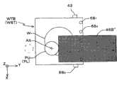
图9中,在投影单元PU最下端部的+Y侧配置有细长长方形板状的标尺构件46B”。此标尺构件46B”具有与前述标尺构件46B’相同的大小(长度及宽度)。其中,在此标尺构件46B”的表面(-Z侧的面),形成有由以Y轴方向为周期方向的既定间距例如1μm的光栅与以X轴方向为周期方向的既定间距例如1μm的光栅所构成的反射型二维绕射光栅。In FIG. 9 , an elongated rectangular plate-shaped
又,在晶片台WTB上面,以与前述图8的读头群641~645相同的配置,在Y轴方向上相隔既定间隔配置有五个二维读头(2D读头)681~685。作为各二维读头,例如构成为包含:使测量光束往+Z方向射出、并使此测量光束自二维绕射光栅的既定次数的绕射光聚光的一对X绕射光栅及一对Y绕射光栅(固定标尺);对在这些一对X绕射光栅及一对Y绕射光栅分别聚光的绕射光进行干涉的由透射型二维绕射光栅所构成的指示标尺(index scale);以及检测由指示标尺干涉的光的检测器。即,能使用所谓三绕射干涉方式的二维编码器读头作为2D读头681~685。此外,代替2D读头,也可组合使用以X轴方向为测量方向的一维读头(X读头)与以Y轴方向为测量方向的一维读头(Y读头)。此时,测量光束的照射位置,在X读头与Y读头中可以不相同。此外,本说明书中使用「二维读头」用语,作为包含如上述X读头与Y读头的组合这样的两个一维读头的组合的概念。Also, on the wafer table WTB, five two-dimensional heads (2D heads) 68 1 to68 are arranged at predetermined intervals in the Y-axis direction in the same arrangement as the head groups 641 to 645 in FIG. 8 described above. 685 . Each two-dimensional read head is configured to include, for example, a pair of X diffraction gratings and a pair of X diffraction gratings that emit a measurement beam in the +Z direction and condense the measurement beam from a predetermined order of diffracted light from the two-dimensional diffraction grating. Y diffraction grating (fixed scale); an index scale (index scale) composed of a transmissive two-dimensional diffraction grating that interferes with the diffracted light condensed on these pair of X diffraction gratings and a pair of Y diffraction gratings. ); and a detector for detecting light interfered by the indicating scale. That is, a two-dimensional encoder head of a so-called three-diffraction interference method can be used as the 2D heads 681 to 685 . In addition, instead of the 2D head, a one-dimensional head (X head) whose measurement direction is the X-axis direction and a one-dimensional head (Y head) whose measurement direction is the Y-axis direction may be used in combination. In this case, the irradiation position of the measurement beam may be different between the X head and the Y head. In addition, the term "two-dimensional head" is used in this specification as a concept including the combination of two one-dimensional heads like the combination of the X head and Y head mentioned above.
在具备此图9所示构成的编码器系统的载台装置中,在晶片W位于投影光学系统PL下方、曝光时的晶片载台WST的移动范围内,至少两个相邻的2D读头68i、68i+1(i=1~4的任一者)同时对向于标尺构件46B”。即,对向于标尺构件46B”的2D读头68i、68i+1所构成的两个二维编码器的测量值被供应至主控制装置20。主控制装置20根据基于这些两个编码器的测量值算出的晶片载台WST在X轴及Y轴方向的位置信息与θz方向的旋转信息,通过晶片载台驱动系统27进行晶片载台WST的位置控制。由此,与上述实施形态完全同样地,能进行高精度的晶片载台WST的二维驱动。In the stage device having the encoder system as shown in FIG. 9 , at least two adjacent 2D heads 68 are positioned within the moving range of wafer stage WST during exposure when the wafer W is located below the projection optical system PL.iand 68i+1 (any one of i=1 to 4) face the
此外,在不需测量晶片载台WST在θz方向的旋转信息时,或使用由干涉仪系统18所测量的θz方向的旋转信息时等,也可采用2D读头681~685中的至少一个对向于标尺构件46B”的构成。此情形下,取代标尺构件46B”也可以设置两个形成有二维绕射光栅的标尺构件。如上所述,能抑制一个标尺构件的大小且至少覆盖曝光动作时的晶片载台WST的移动范围全区。此时,两个标尺构件,可配置成各自的长边方向彼此正交,或配置成长边方向为同一方向。In addition, when it is not necessary to measure the rotation information of the wafer stage WST in the θz direction, or when the rotation information in the θz direction measured by the
又,上述各实施形态中,虽在晶片的曝光动作中使用前述编码器系统进行晶片载台WST的位置控制,但例如在对准动作(至少包含利用对准系统ALG进行的标记检测动作)及/或晶片的更换动作等中,也可使用图3、图8、及图9等所示的编码器系统进行晶片载台WST的位置控制。此时,当然不需要前述位置测量系统的切换动作。In addition, in each of the above-mentioned embodiments, although the aforementioned encoder system is used to control the position of wafer stage WST in the exposure operation of the wafer, for example, in the alignment operation (including at least the mark detection operation by the alignment system ALG) and In/or the wafer exchange operation, etc., the position control of wafer stage WST may be performed using the encoder system shown in FIG. 3, FIG. 8, and FIG. 9, etc. FIG. In this case, of course, the aforementioned switching action of the position measuring system is unnecessary.
此处,利用对准系统ALG检测晶片W上的对准标记或晶片载台WST的基准标记时等也同样地,在使用前述编码器系统(图3、图8及图9)时,最好是还考虑在此检测动作时晶片载台WST的移动范围,来设定读头的配置(包含例如位置、数目的至少一个)及/或标尺构件的配置(包含例如位置、数目、大小的至少一个)等。即,即使在将晶片载台WST移动至对准系统ALG的测量位置而进行的标记的检测动作中,为了能进行例如在X轴、Y轴、以及θz方向的三个自由度的位置测量,最好将读头及/或标尺构件的配置设定成总是有至少三个读头与对应的同一及/或相异的标尺构件(绕射光栅)持续对向、即避免无法利用编码器系统测量位置从而使晶片载台的位置控制中断的情形。此时,例如可以将上述各实施形态的标尺构件的大小设定成可在曝光动作与对准动作中兼用,或也可以与前述标尺构件另外独立地设置在对准动作中使用的标尺构件。特别是后者,例如对对准系统ALG,也以与图3、图8、图9等所示的配置相同的配置设置标尺构件即可。或者,也可使用在曝光动作中使用的多个标尺构件的至少一个与另外设置的至少一个标尺构件,在对准动作等中也利用编码器系统进行晶片载台WST的位置测量。Here, also when using the alignment system ALG to detect the alignment mark on the wafer W or the reference mark on the wafer stage WST, etc., when the aforementioned encoder system (FIG. 3, FIG. 8 and FIG. 9) is used, it is preferable to Also consider the movement range of the wafer stage WST during this detection operation to set the configuration of the read head (including at least one of the position and number) and/or the configuration of the scale member (including at least one of the position, number and size) a) etc. That is, even in the mark detection operation performed by moving wafer stage WST to the measurement position of alignment system ALG, in order to perform position measurement of three degrees of freedom in the X-axis, Y-axis, and θz directions, for example, Preferably, the configuration of the read heads and/or scale members is set such that there are always at least three read heads facing the corresponding identical and/or different scale members (diffraction gratings) continuously, i.e. to avoid unavailability of the encoder A situation in which the system measures position such that control of the position of the wafer stage is interrupted. In this case, for example, the size of the scale member in each of the above-described embodiments may be set to be used in both the exposure operation and the alignment operation, or a scale member used in the alignment operation may be provided separately from the above-mentioned scale member. In particular, for the latter, for example, the alignment system ALG may be provided with a scale member in the same arrangement as that shown in FIGS. 3 , 8 , and 9 . Alternatively, at least one of the plurality of scale members used in the exposure operation and at least one separate scale member may be used to measure the position of wafer stage WST by the encoder system also in the alignment operation or the like.
此外,在利用前述标线片对准系统检测晶片载台WST的基准标记时、及/或利用前述空间像测量系统检测标线片R的标记或标线片载台RST的基准标记的投影像时,虽然也可利用前述干涉仪系统进行晶片载台WST的位置测量,但最好是利用包含上述各实施形态的标尺构件的编码器系统进行晶片载台WST的位置测量。In addition, when using the aforementioned reticle alignment system to detect the fiducial mark on wafer stage WST, and/or using the aforementioned aerial image measurement system to detect the mark on reticle R or the projected image of the fiducial mark on reticle stage RST In this case, although the position measurement of wafer stage WST can be performed by the aforementioned interferometer system, it is preferable to perform the position measurement of wafer stage WST by use of an encoder system including the scale member of each of the above-mentioned embodiments.
又,当在晶片的更换位置(包含装载位置与卸载位置的至少一方)上有晶片载台WST时,在使用前述编码器系统(图3、图8、以及图9)的情况下,最好还考虑在晶片更换动作中的晶片载台WST的移动范围,与前述同样地设定读头及/或标尺构件的配置等。即,最好是将读头及/或标尺构件的配置设定成,即使在晶片更换位置也避免无法利用编码器系统测量位置从而使晶片载台的位置控制中断的情形。又,在晶片的更换位置与经由投影光学系统PL进行标线片图案的转印的曝光位置或利用对准系统ALG进行标记检测的测量位置之间、及/或对准系统ALG的测量位置与曝光位置之间的晶片载台WST的移动中,使用前述编码器系统(图3、图8及图9)的情形也同样。Also, when there is a wafer stage WST at the wafer exchange position (including at least one of the loading position and the unloading position), it is preferable to use the aforementioned encoder system (FIG. 3, FIG. 8, and FIG. 9). Also considering the movement range of wafer stage WST during the wafer exchange operation, the arrangement of the head and/or the scale member and the like are set in the same manner as described above. That is, it is preferable to set the arrangement of the head and/or the scale member so as not to interrupt the position control of the wafer stage because the position cannot be measured by the encoder system even at the wafer exchange position. Also, between the replacement position of the wafer and the exposure position where the reticle pattern is transferred via the projection optical system PL or the measurement position where the mark detection is performed by the alignment system ALG, and/or between the measurement position of the alignment system ALG and The same applies to the case where the aforementioned encoder system ( FIG. 3 , FIG. 8 , and FIG. 9 ) is used for movement of wafer stage WST between exposure positions.
再者,即使在例如美国专利第6,262,796号说明书等所揭示,可使用两个晶片载台大致并行执行曝光动作与测量动作(例如基于对准系统的标记检测等)的双晶片载台方式的曝光装置中,也与上述各实施形态同样地,可使用读头设于各晶片载台的前述编码器系统(图3、图8及图9)进行各晶片载台的位置控制。此处,不仅在曝光动作时,在其它动作例如在测量动作时,也可通过与前述同样地适当设定读头及/或标尺构件的配置,由此利用前述编码器系统进行各晶片载台的位置测量。例如,通过适当设定读头的配置,可将上述各实施形态的标尺构件直接使用来进行各晶片载台的位置控制,但也可与前述标尺构件分开设置能在该测量动作中使用的标尺构件。此时,例如可以设置具有与上述各实施形态的标尺构件相同的配置,例如以对准系统ALG为中心配置成十字状的四个标尺构件,在上述测量动作时,利用这些标尺构件与所对应的读头测量各晶片载台WST的位置信息。双晶片载台方式的曝光装置中,例如分别以与前述同样的配置设置读头(图3、图8及图9),且在装载于一晶片载台的晶片的曝光动作结束时,通过与该一晶片载台更换,将装载有已在测量位置进行了标记检测等的下一晶片的另一晶片载台配置于曝光位置。又,与曝光动作并行进行的测量动作,并不限于基于对准系统对晶片等的标记检测,也可代替其方式或以与该方式组合的方式,进行晶片的面信息(段差信息等)的检测。Furthermore, even as disclosed in, for example, U.S. Patent No. 6,262,796, two wafer stages can be used to perform exposure operations and measurement operations (such as mark detection based on an alignment system, etc.) approximately in parallel in the exposure of the dual wafer stage method. Also in the apparatus, similarly to the above-described embodiments, the position control of each wafer stage can be performed using the aforementioned encoder system (FIGS. 3, 8, and 9) provided with a head on each wafer stage. Here, not only during the exposure operation, but also during other operations such as the measurement operation, by appropriately setting the arrangement of the read head and/or the scale member in the same manner as described above, each wafer stage can be performed using the aforementioned encoder system. position measurement. For example, by appropriately setting the arrangement of the read head, the scale member of each of the above-mentioned embodiments can be used as it is to control the position of each wafer stage, but it is also possible to provide a scale that can be used for the measurement operation separately from the above-mentioned scale member. member. At this time, for example, it is possible to set four scale members having the same arrangement as the scale members of the above-mentioned embodiments, for example, four scale members arranged in a cross shape centered on the alignment system ALG. The read head measures the position information of each wafer stage WST. In the exposure apparatus of the two-wafer stage system, for example, the read heads are arranged in the same arrangement as described above (FIG. 3, FIG. 8, and FIG. 9), and when the exposure operation of the wafer loaded on one wafer stage is completed, the This one wafer stage is replaced, and another wafer stage on which the next wafer on which mark detection etc. have been performed at the measurement position is placed is placed at the exposure position. In addition, the measurement operation performed in parallel with the exposure operation is not limited to the detection of marks on the wafer or the like by the alignment system, and instead of or in combination with this method, the surface information (level difference information, etc.) of the wafer may be measured. detection.
此外,上述说明中,在测量位置或更换位置中,或晶片载台从曝光位置、测量位置、及更换位置的一位置往另一位置的移动过程中,当使用前述编码器系统的晶片载台的位置控制中断时,最好使用与该编码器系统不同的测量装置(例如干涉仪、编码器等),在上述各位置或移动过程中进行晶片载台的位置控制。In addition, in the above description, when the wafer stage using the aforementioned encoder system When the position control of the wafer stage is interrupted, it is preferable to use a measuring device (such as an interferometer, an encoder, etc.) different from the encoder system to control the position of the wafer stage during the above-mentioned positions or movements.
又,上述各实施形态中,也可如例如国际公开第2005/074014号小册子(对应美国专利申请公开第2007/0127006号说明书)等所揭示,与晶片载台分开独立设置测量载台,在晶片更换动作时等通过与晶片载台的更换将测量载台配置于投影光学系统PL的正下方,以测量曝光装置的特性(例如投影光学系统的成像特性(波面像差)、照明光IL的偏光特性等)。此时,在测量载台上也可以配置读头,并使用前述标尺构件进行测量载台的位置控制。又,在装载于晶片载台的晶片的曝光动作中,测量载台退离至不与晶片载台干涉的既定位置,由此在该退离位置与曝光位置之间进行移动。因此,即使在该退离位置、或从该退离位置与曝光位置的一方移动至另一方的期间中,也与晶片载台同样地,最好还考虑测量载台的移动范围,与前述同样地将读头及/或标尺构件的配置等设定成避免发生无法利用编码器系统测量位置从而使测量载台的位置控制中断的情形。或者,在该退离位置或在该移动中利用前述编码器系统对测量载台进行的位置控制中断时,最好使用与该编码器系统不同的测量装置(例如干涉仪、编码器等)进行测量载台的位置控制。或者,测量载台的位置控制也可仅用前述干涉仪系统进行。In addition, in each of the above embodiments, as disclosed in International Publication No. 2005/074014 pamphlet (corresponding to U.S. Patent Application Publication No. 2007/0127006 specification), it is also possible to independently install the measurement stage separately from the wafer stage, and The measurement stage is placed directly below the projection optical system PL by replacing it with the wafer stage during wafer exchange operations, etc., to measure the characteristics of the exposure device (such as the imaging characteristics (wavefront aberration) of the projection optical system, and the intensity of the illumination light IL). polarizing properties, etc.). In this case, the reading head may be arranged on the measurement stage, and the position control of the measurement stage may be performed using the aforementioned scale member. Also, during the exposure operation of the wafer mounted on the wafer stage, the measurement stage moves away to a predetermined position where it does not interfere with the wafer stage, thereby moving between the retracted position and the exposure position. Therefore, even during the retracted position or the period of moving from one of the retracted position and the exposure position to the other, as with the wafer stage, it is preferable to also consider the movement range of the measurement stage, as described above. The arrangement of the read head and/or the scale member, etc. is carefully set to avoid a situation in which the position cannot be measured by the encoder system, thereby interrupting the position control of the measuring stage. Alternatively, when the position control of the measuring stage by the aforementioned encoder system is interrupted in the withdrawn position or in the movement, it is preferably carried out using a measuring device (such as an interferometer, encoder, etc.) different from the encoder system. Position control of the measuring stage. Alternatively, the position control of the measuring stage can also be carried out exclusively with the aforementioned interferometer system.
又,上述各实施形态中,随着例如投影单元PU的大小等的不同,而必须对延伸设置于同一方向的一对标尺构件的间隔进行扩大,这样,在对晶片W上的特定照射区域例如位于最外周的照射区域进行扫描曝光时,对于该一对标尺构件的其中一方,对应于此的读头有时变得无法对向。例如,当图3中投影单元PU稍微增大时,对于一对标尺构件46B,46D中的标尺构件46B,对应的X读头66的任一者均无法对向。再者,例如国际公开WO99/49504号小册子等所揭示,在投影光学系统PL与晶片间充满液体(例如纯水等)的液浸型曝光装置中,由于供应液体的嘴构件等设置成包围投影单元PU,因此更难以将读头接近投影光学系统PL的前述曝光区域来配置。因此,当在液浸型曝光装置中采用图3的编码器系统时,编码器系统不需构成为能总是在X轴及Y轴方向分别测量各两个位置信息,而只要构成为能在X轴及Y轴方向中的一方测量两个位置信息、及在另一方测量一个位置信息即可。即,在利用编码器系统对晶片载台(或测量载台)进行位置控制时,不一定要在X轴及Y轴方向分别使用各两个、合计四个的位置信息。In addition, in each of the above-mentioned embodiments, the distance between the pair of scale members extended in the same direction must be enlarged according to the size of the projection unit PU, for example. When scanning exposure is performed on the shot area located in the outermost periphery, the corresponding read head may not be able to face one of the pair of scale members. For example, when the projection unit PU is slightly enlarged in FIG. 3 , for the
又,上述各实施形态中,干涉仪系统18的构成不限于图3,例如在对准系统ALG(测量位置)中也配置标尺构件时等,也可不具备晶片X干涉仪18X2,可将晶片X干涉仪18X2例如与晶片Y干涉仪18Y同样地由多轴干涉仪构成,且使其不但能测量晶片载台WST的X位置,还能测量旋转信息(例如偏摇及横摇)。再者,上述各实施形态中,虽然为了进行编码器系统的校正或在曝光动作以外的其它动作中进行晶片载台的位置测量而使用干涉仪系统18,但并不限于此,也可在曝光动作、测量动作(包含对准动作)等的至少一个动作中,并用编码器系统50与干涉仪系统18。例如当编码器系统50无法测量或其测量值有异常时,可切换至干涉仪系统18而持续晶片载台WST的位置控制。此外,上述各实施形态中也可不设置干涉仪系统18,而仅设置前述编码器系统。In addition, in each of the above-mentioned embodiments, the configuration of the
又,上述各实施形态中,虽然由编码器系统50测量晶片载台WST在X轴及Y轴的至少一方的位置,但并不限于此,也可进行在Z轴方向的位置测量。例如也可与前述读头分别独立地将能测量Z轴方向的位置的编码器方式的读头设于晶片载台,也可将前述读头作成能测量X轴及Y轴方向的至少一方的位置与Z轴方向的位置的读头。Also, in each of the above-mentioned embodiments, the
又,图3、图8所示的编码器系统中,也可将X读头、Y读头的至少一方替代成2D读头,将与此2D读头对向的标尺构件作成形成有二维绕射光栅的标尺构件。此时,在图3所示的编码器系统中,可将标尺构件的数目从四个最小减至两个,在图8的编码器系统中,通过特别是将标尺构件46B’作成形成有二维绕射光栅的标尺构件,可使其宽度变窄。Also, in the encoder system shown in Fig. 3 and Fig. 8, at least one of the X read head and the Y read head can be replaced by a 2D read head, and the scale member facing the 2D read head can be made to form a two-dimensional Ruler component for diffraction gratings. At this time, in the encoder system shown in FIG. 3, the number of scale members can be reduced from four to two at a minimum. In the encoder system of FIG. Scale member of a three-dimensional diffraction grating to narrow its width.
又,上述各实施形态中,采用能对一个标尺构件总是照射多个测量光束的构成,当一个测量光束为异常时,也可切换至另一测量光束来继续进行测量。此时,多个测量光束,可从一个读头照射于标尺构件,或可从不同的多个读头照射。当对一个标尺构件照射多个测量光束时,该多个测量光束最好照射于标尺构件上不同的位置。Furthermore, in each of the above-mentioned embodiments, a plurality of measuring beams can always be irradiated to one scale member, and when one measuring beam becomes abnormal, it is possible to switch to another measuring beam and continue measurement. In this case, a plurality of measuring beams may be irradiated on the scale member from one head, or may be irradiated from a plurality of different heads. When one scale member is irradiated with a plurality of measuring beams, it is preferable that the plurality of measuring beams are irradiated at different positions on the scale member.
又,前述各标尺构件,也可通过将多个小标尺构件一体保持于板构件等来构成。此时,当对向于小标尺构件彼此的连接部的读头无法测量或测量异常时,也可以用利用对向于连接部以外的部分的其它读头进行的位置测量来代替。In addition, each of the aforementioned scale members may be configured by integrally holding a plurality of small scale members on a plate member or the like. At this time, if the head facing the connecting portion of the small scale members cannot measure or the measurement is abnormal, position measurement by another head facing a portion other than the connecting portion may be used instead.
又,上述各实施形态所说明的读头的配置仅为一例子,读头的配置并不限定于此。In addition, the arrangement of the heads described in each of the above embodiments is merely an example, and the arrangement of the heads is not limited thereto.
又,上述各实施形态中,标尺构件虽然通过支撑构件以悬吊状态固定于镜筒固定座,但也能由镜筒固定座以外的其它保持构件来保持标尺构件。又,上述各实施形态中,也可以视需要进行标尺构件的调温。In addition, in each of the above-mentioned embodiments, the scale member is fixed to the barrel holder in a suspended state by the support member, but the scale member can also be held by other holding members than the barrel holder. In addition, in each of the above-mentioned embodiments, the temperature of the scale member may be adjusted as necessary.
又,上述各实施形态中,由于不需对应晶片载台WST的移动范围全区来配置标尺(光栅),因此也有能容易地进行空调等的效果。Furthermore, in each of the above-mentioned embodiments, since it is not necessary to arrange scales (gratings) corresponding to the entire moving range of wafer stage WST, there is also an effect that air conditioning and the like can be easily performed.
此外,上述各实施形态中,虽然说明了将本发明适用于扫描步进器的情形,但并不限于此,也可将本发明适用于步进器等的静止型曝光装置。即使是步进器等,也可通过利用编码器测量装载有曝光对象的物体的载台的位置,从而与使用干涉仪测量该载台位置的情形不同地,能够使起因于空气摇晃所导致的位置测量误差的发生成为几乎零,并能根据编码器的测量值高精度地定位载台,其结果能高精度地将标线片的图案转印至物体上。又,也可将本发明适用于合成照射区域与照射区域的步进接合方式的缩小投影曝光装置。In addition, in each of the above-mentioned embodiments, the case where the present invention is applied to a scanning stepper has been described, but the present invention is not limited thereto, and the present invention can also be applied to a stationary type exposure apparatus such as a stepper. Even if it is a stepper, etc., by using an encoder to measure the position of the stage on which the object to be exposed is placed, it is possible to reduce the position of the stage caused by the vibration of the air, unlike the case where the position of the stage is measured using an interferometer. The occurrence of position measurement error becomes almost zero, and the stage can be positioned with high precision based on the measurement value of the encoder, and as a result, the pattern of the reticle can be transferred to the object with high precision. In addition, the present invention can also be applied to a reduction projection exposure apparatus of a step-and-stitch method for synthesizing shot areas and shot areas.
又,上述各实施形态的曝光装置中的投影光学系统并不仅可为缩小系统,也可为等倍系统及放大系统的任一者,投影光学系统PL不仅可为折射系统,也可为反射系统及反折射系统的任一者,其投影像也可以是倒立像与正立像的任一者。In addition, the projection optical system in the exposure apparatus of each of the above-mentioned embodiments may be not only a reduction system, but may also be any one of an equal magnification system and an enlargement system, and the projection optical system PL may be not only a refraction system, but also a reflection system. And any one of the catadioptric system, the projected image can also be any one of the inverted image and the erected image.
又,照明光IL,不限于ArF准分子激光光束(波长193nm),也能使用KrF准分子激光光束(波长248nm)等紫外光、F2激光光束(波长157nm)等真空紫外光。作为真空紫外光,也可使用美国专利第7,023,610号说明书所揭示的谐波,其是将从DFB半导体激光器或纤维激光器振荡出的红外线区或可视区的单一波长激光光束,用涂布有铒(或铒及镱两者)的光纤放大器进行放大,并用非线形光学结晶转换波长成紫外光而得到的。In addition, the illumination light IL is not limited to ArF excimer laser beam (wavelength 193nm), and ultraviolet light such as KrF excimer laser beam (wavelength 248nm), vacuum ultraviolet light such asF2 laser beam (wavelength 157nm) can also be used. As vacuum ultraviolet light, the harmonics disclosed in the US Patent No. 7,023,610 specification can also be used, which is a single-wavelength laser beam in the infrared region or visible region oscillated from a DFB semiconductor laser or fiber laser, coated with erbium (or both erbium and ytterbium) fiber amplifiers to amplify, and use nonlinear optical crystals to convert wavelengths into ultraviolet light.
又,上述各实施形态中,作为曝光装置的照明光IL,并不限于波长大于100nm的光,当然也可使用波长小于100nm的光。例如可将本发明适用于使用软X线区域(例如5~15nm的波长域)的EUV(Extreme UltraViolet,超紫外线)光的EUV曝光装置。此外,本发明也适用于使用电子射线或离子束等的带电粒子射线的曝光装置。In addition, in each of the above-described embodiments, the illumination light IL of the exposure device is not limited to light having a wavelength greater than 100 nm, and of course light having a wavelength less than 100 nm may also be used. For example, the present invention can be applied to an EUV exposure apparatus using EUV (Extreme UltraViolet) light in a soft X-ray region (for example, a wavelength region of 5 to 15 nm). In addition, the present invention is also applicable to an exposure apparatus using charged particle beams such as electron beams and ion beams.
又,上述各实施形态中,虽然使用了在光透射性的基板上形成有既定遮光图案(或相位图案,减光图案)的光透射性掩模(标线片),但也可使用例如美国专利第6,778,257号说明书所揭示的电子掩模来代替此标线片,该电子掩模(也称为可变成形掩模、主动掩模、或图像产生器,例如包含非发光型图像显示元件(空间光调制器)的一种的DMD(Digital Micro-mirror Device,数字微镜器件)等)根据要曝光图案的电子数据来形成透射图案或反射图案、或发光图案。使用上述可变成形掩模时,搭载有晶片或玻璃板等的载台由于对可变成形掩模进行扫描,因此通过使用编码器测量该载台的位置,即能得到与上述各实施形态同等的效果。Also, in each of the above-mentioned embodiments, although a light-transmitting mask (reticle) having a predetermined light-shielding pattern (or phase pattern, or light-reducing pattern) formed on a light-transmitting substrate is used, it is also possible to use, for example, a U.S. Instead of the reticle, the electronic mask disclosed in the Specification No. 6,778,257, which is also called a variable shape mask, an active mask, or an image generator, includes, for example, a non-emissive image display element A DMD (Digital Micro-mirror Device, digital micromirror device), a kind of (spatial light modulator), etc.) forms a transmission pattern or a reflection pattern, or a light-emitting pattern according to the electronic data of the pattern to be exposed. When the above-mentioned variable shape mask is used, since the stage on which the wafer or glass plate is mounted scans the variable shape mask, by using an encoder to measure the position of the stage, it is possible to obtain same shape effect.
又,本发明也能适用于,例如国际公开第2001/035168号小册子所揭示,通过将干涉纹形成于晶片W上、而在晶片W上形成等间隔线图案(line and space pattern)的曝光装置(光刻系统)。In addition, the present invention can also be applied to the exposure method for forming a line and space pattern at equal intervals on the wafer W by forming interference fringes on the wafer W, as disclosed in the pamphlet of International Publication No. 2001/035168, for example. device (lithography system).
进而,例如也能将本发明适用于例如美国专利第6,611,316号说明书所揭示的曝光装置,该曝光装置将两个标线片图案通过投影光学系统在晶片上合成,由一次的扫描曝光来对晶片上的一个照射区域大致同时进行双重曝光。Furthermore, for example, the present invention can also be applied to the exposure apparatus disclosed in the specification of U.S. Patent No. 6,611,316. This exposure apparatus synthesizes two reticle patterns on a wafer through a projection optical system, and performs scanning exposure on the wafer once. A irradiated area on the above double exposure at approximately the same time.
又,在物体上形成图案的装置并不限于前述曝光装置(光刻系统),例如也能将本发明适用于以喷墨式来将图案形成于物体上的装置。Also, the apparatus for forming a pattern on an object is not limited to the aforementioned exposure apparatus (lithography system), and the present invention can also be applied to an apparatus for forming a pattern on an object by an inkjet method, for example.
此外,上述实施形态中,待形成图案的物体(能量束所照射的曝光对象的物体)并不限于晶片,也可以是玻璃板、陶瓷基板、膜构件、或者掩模底版(mask blank)等其它物体。In addition, in the above-mentioned embodiment, the object to be patterned (the object to be exposed to energy beam irradiation) is not limited to a wafer, and may be a glass plate, a ceramic substrate, a film member, or a mask blank (mask blank), etc. object.
曝光装置的用途并不限定于半导体制造用的曝光装置,也可广泛适用于例如将液晶显示元件图案转印于方型玻璃板的液晶用曝光装置,或用于制造有机EL、薄膜磁头、摄影元件(CCD等)、微型机器及DNA芯片等的曝光装置。又,除了制造半导体元件等微型器件以外,为了制造在光曝光装置、EUV(超紫外线)曝光装置、X射线曝光装置及电子射线曝光装置等中使用的标线片或掩模,也能将本发明适用于用以将电路图案转印至玻璃基板或硅晶片等的曝光装置。The application of the exposure device is not limited to the exposure device for semiconductor manufacturing, but can also be widely used in the exposure device for liquid crystals, such as transferring the pattern of the liquid crystal display element to the square glass plate, or for the production of organic EL, thin film magnetic head, photography, etc. Exposure equipment for components (CCD, etc.), micromachines, and DNA chips. Moreover, in addition to manufacturing microdevices such as semiconductor elements, in order to manufacture reticles or masks used in light exposure equipment, EUV (extreme ultraviolet) exposure equipment, X-ray exposure equipment, and electron beam exposure equipment, the present invention can also be used. The invention is applicable to an exposure device for transferring a circuit pattern to a glass substrate, a silicon wafer, or the like.
此外,本发明的移动体驱动装置并不限定于曝光装置,也可广泛适用于其它的基板处理装置(例如激光修理装置、基板检查装置等其它),或其它精密机械中的试料定位装置、打线(wire bonding)装置等具备移动载台的装置。In addition, the moving body driving device of the present invention is not limited to the exposure device, and can also be widely applied to other substrate processing devices (such as laser repair devices, substrate inspection devices, etc.), or sample positioning devices in other precision machinery, Wire bonding devices and other devices equipped with mobile stages.
此外,援用与截至目前为止的说明中所引用的曝光装置等相关的所有公报、国际公开小册子、美国专利申请公开说明书及美国专利说明书的揭示,来作为本说明书的记载的一部分。In addition, disclosures of all publications, international publication pamphlets, US patent application publications, and US patent specifications related to the exposure apparatuses cited in the previous descriptions are incorporated as part of the description of this specification.
又,半导体器件经由下述步骤制造,即:进行器件的功能、性能设计的步骤、根据此设计步骤制作标线片的步骤、由硅材料制作晶片的步骤、由通过前述调整方法而已调整图案的转印特性的上述各实施形态的曝光装置将形成于掩模的图案转印于晶片等物体上的光刻步骤、使已曝光的晶片显影的显影步骤、通过蚀刻除去抗蚀剂残存部分以外的部分的露出构件的蚀刻步骤、除去结束蚀刻后不需要的抗蚀剂的抗蚀剂除去步骤、器件组装步骤(包含切割工序、接合工序、封装工序)、检查步骤等。此时,由于在光刻步骤中使用上述各实施形态的曝光装置,因此能以高成品率制造高集成度的器件。In addition, the semiconductor device is manufactured through the following steps: the step of designing the function and performance of the device, the step of making a reticle according to the design step, the step of making a wafer from silicon material, and the step of adjusting the pattern by the aforementioned adjustment method. The exposure apparatus of each of the above-mentioned embodiments of the transfer characteristic includes a photolithography step of transferring a pattern formed on a mask onto an object such as a wafer, a developing step of developing an exposed wafer, and removing resist residues by etching. Etching process for partially exposed members, resist removal process for removing unnecessary resist after etching, device assembly process (including dicing process, bonding process, packaging process), inspection process, etc. In this case, since the exposure apparatuses of the above-described embodiments are used in the photolithography step, highly integrated devices can be manufactured with high yield.
产业上的可利用性Industrial availability
如以上的说明,本发明的移动体驱动系统适于沿既定平面驱动移动体。又,本发明的图案形成装置适于在晶片等物体上形成图案。又,本发明的曝光装置、曝光方法、以及器件制造方法,适于制造半导体元件等电子器件。As explained above, the moving body driving system of the present invention is suitable for driving the moving body along a predetermined plane. Also, the pattern forming apparatus of the present invention is suitable for forming a pattern on an object such as a wafer. Moreover, the exposure apparatus, exposure method, and device manufacturing method of this invention are suitable for manufacturing electronic devices, such as a semiconductor element.
Claims (31)
Translated fromChineseApplications Claiming Priority (3)
| Application Number | Priority Date | Filing Date | Title |
|---|---|---|---|
| JP340706/2007 | 2007-12-28 | ||
| JP2007340706 | 2007-12-28 | ||
| PCT/JP2008/003950WO2009084196A1 (en) | 2007-12-28 | 2008-12-25 | Moving body driving system, pattern forming apparatus, exposure apparatus, exposure method and device manufacturing method |
Publications (2)
| Publication Number | Publication Date |
|---|---|
| CN101680747A CN101680747A (en) | 2010-03-24 |
| CN101680747Btrue CN101680747B (en) | 2012-11-07 |
Family
ID=40823932
Family Applications (1)
| Application Number | Title | Priority Date | Filing Date |
|---|---|---|---|
| CN200880019418XAExpired - Fee RelatedCN101680747B (en) | 2007-12-28 | 2008-12-25 | Moving body driving system, pattern forming apparatus, exposure apparatus and exposure method, and device manufacturing method |
Country Status (6)
| Country | Link |
|---|---|
| US (2) | US8237916B2 (en) |
| JP (1) | JP5131281B2 (en) |
| KR (1) | KR101549710B1 (en) |
| CN (1) | CN101680747B (en) |
| TW (1) | TWI451203B (en) |
| WO (1) | WO2009084196A1 (en) |
Families Citing this family (37)
| Publication number | Priority date | Publication date | Assignee | Title |
|---|---|---|---|---|
| US8228482B2 (en)* | 2008-05-13 | 2012-07-24 | Nikon Corporation | Exposure apparatus, exposure method, and device manufacturing method |
| US8817236B2 (en) | 2008-05-13 | 2014-08-26 | Nikon Corporation | Movable body system, movable body drive method, pattern formation apparatus, pattern formation method, exposure apparatus, exposure method, and device manufacturing method |
| US8786829B2 (en)* | 2008-05-13 | 2014-07-22 | Nikon Corporation | Exposure apparatus, exposure method, and device manufacturing method |
| US8902402B2 (en) | 2008-12-19 | 2014-12-02 | Nikon Corporation | Movable body apparatus, exposure apparatus, exposure method, and device manufacturing method |
| US8760629B2 (en) | 2008-12-19 | 2014-06-24 | Nikon Corporation | Exposure apparatus including positional measurement system of movable body, exposure method of exposing object including measuring positional information of movable body, and device manufacturing method that includes exposure method of exposing object, including measuring positional information of movable body |
| US8599359B2 (en) | 2008-12-19 | 2013-12-03 | Nikon Corporation | Exposure apparatus, exposure method, device manufacturing method, and carrier method |
| US8773635B2 (en)* | 2008-12-19 | 2014-07-08 | Nikon Corporation | Exposure apparatus, exposure method, and device manufacturing method |
| US8514395B2 (en)* | 2009-08-25 | 2013-08-20 | Nikon Corporation | Exposure method, exposure apparatus, and device manufacturing method |
| US8493547B2 (en)* | 2009-08-25 | 2013-07-23 | Nikon Corporation | Exposure apparatus, exposure method, and device manufacturing method |
| US8488109B2 (en) | 2009-08-25 | 2013-07-16 | Nikon Corporation | Exposure method, exposure apparatus, and device manufacturing method |
| JP2011054694A (en)* | 2009-08-31 | 2011-03-17 | Canon Inc | Measurement apparatus, exposure apparatus, and device manufacturing method |
| US20110096306A1 (en)* | 2009-09-28 | 2011-04-28 | Nikon Corporation | Stage apparatus, exposure apparatus, driving method, exposing method, and device fabricating method |
| US20110096318A1 (en)* | 2009-09-28 | 2011-04-28 | Nikon Corporation | Exposure apparatus and device fabricating method |
| US20110096312A1 (en)* | 2009-09-28 | 2011-04-28 | Nikon Corporation | Exposure apparatus and device fabricating method |
| US20110102761A1 (en)* | 2009-09-28 | 2011-05-05 | Nikon Corporation | Stage apparatus, exposure apparatus, and device fabricating method |
| US20110128523A1 (en)* | 2009-11-19 | 2011-06-02 | Nikon Corporation | Stage apparatus, exposure apparatus, driving method, exposing method, and device fabricating method |
| US20110123913A1 (en)* | 2009-11-19 | 2011-05-26 | Nikon Corporation | Exposure apparatus, exposing method, and device fabricating method |
| US8488106B2 (en)* | 2009-12-28 | 2013-07-16 | Nikon Corporation | Movable body drive method, movable body apparatus, exposure method, exposure apparatus, and device manufacturing method |
| JP2012032215A (en)* | 2010-07-29 | 2012-02-16 | Mitsutoyo Corp | Industrial machine |
| US20120064460A1 (en)* | 2010-09-07 | 2012-03-15 | Nikon Corporation | Movable body apparatus, object processing device, exposure apparatus, flat-panel display manufacturing method, and device manufacturing method |
| JP6156147B2 (en) | 2011-11-17 | 2017-07-05 | 株式会社ニコン | Encoder apparatus, optical apparatus, exposure apparatus, and device manufacturing method |
| US9207549B2 (en) | 2011-12-29 | 2015-12-08 | Nikon Corporation | Exposure apparatus and exposure method, and device manufacturing method with encoder of higher reliability for position measurement |
| CN103246172B (en)* | 2012-02-10 | 2016-12-28 | 约翰内斯﹒海德汉博士有限公司 | There is the device of multiple scanning elements of position-measurement device |
| EP2629325B1 (en)* | 2012-02-17 | 2014-10-22 | Dr. Johannes Heidenhain GmbH | Assembly and method for positioning a machining tool relative to a workpiece |
| DE102012210309A1 (en)* | 2012-06-19 | 2013-12-19 | Dr. Johannes Heidenhain Gmbh | Position measuring device |
| JP5945632B2 (en) | 2012-08-23 | 2016-07-05 | エーエスエムエル ネザーランズ ビー.ブイ. | Lithographic apparatus, device manufacturing method, and displacement measurement system |
| WO2014053296A1 (en)* | 2012-10-01 | 2014-04-10 | Asml Netherlands B.V. | A method for calibration of an encoder scale and a lithographic apparatus |
| CN203249609U (en)* | 2013-03-26 | 2013-10-23 | 鸿准精密模具(昆山)有限公司 | Dimensional testing device |
| EP3611572B1 (en) | 2013-06-28 | 2023-04-05 | Nikon Corporation | Mobile body apparatus, exposure apparatus, and device manufacturing method |
| US9529280B2 (en)* | 2013-12-06 | 2016-12-27 | Kla-Tencor Corporation | Stage apparatus for semiconductor inspection and lithography systems |
| US10048600B2 (en)* | 2014-03-28 | 2018-08-14 | Nikon Corporation | Movable body apparatus, exposure apparatus, manufacturing method of flat panel display, device manufacturing method, and movable body drive method |
| CN111610696A (en) | 2015-02-23 | 2020-09-01 | 株式会社尼康 | Substrate processing system, substrate processing method, and component manufacturing method |
| KR102688211B1 (en) | 2015-02-23 | 2024-07-24 | 가부시키가이샤 니콘 | Measurement device, lithography system and exposure device, and device manufacturing method |
| TWI878938B (en) | 2015-02-23 | 2025-04-01 | 日商尼康股份有限公司 | Measurement device, exposure apparatus, lithography system, measurement method and exposure method |
| KR102320293B1 (en)* | 2016-09-30 | 2021-11-01 | 가부시키가이샤 니콘 | A moving body apparatus, a moving method, an exposure apparatus, an exposure method, a manufacturing method of a flat panel display, and a device manufacturing method |
| US10416408B2 (en)* | 2017-09-05 | 2019-09-17 | Himax Technologies Limited | Projector assembling equipment |
| US12346010B2 (en)* | 2022-04-29 | 2025-07-01 | International Business Machines Corporation | Alignment system and tool for visual inspection |
Citations (5)
| Publication number | Priority date | Publication date | Assignee | Title |
|---|---|---|---|---|
| EP0482553A2 (en)* | 1990-10-22 | 1992-04-29 | Karl SÀ¼ss KG Präzisionsgeräte für Wissenschaft und Industrie - GmbH & Co. | Measuring device for x,y, gamma alignment tables |
| US5610715A (en)* | 1994-03-30 | 1997-03-11 | Canon Kabushiki Kaisha | Displacement detecting system, an expose apparatus, and a device manufacturing method employing a scale whose displacement is detected by a selected detection head |
| CN1873542A (en)* | 2005-05-24 | 2006-12-06 | Asml荷兰有限公司 | Dual stage lithographic apparatus and device manufacturing method |
| CN1288506C (en)* | 2002-03-15 | 2006-12-06 | Asml荷兰有限公司 | Method for manufacturing photoetching equipment and device |
| CN1932650A (en)* | 2005-09-13 | 2007-03-21 | Asml荷兰有限公司 | Lithographic apparatus and device manufacturing method |
Family Cites Families (36)
| Publication number | Priority date | Publication date | Assignee | Title |
|---|---|---|---|---|
| US41380A (en)* | 1864-01-26 | Improved method of securing tubes in steam-boilers | ||
| US263846A (en)* | 1882-09-05 | brown | ||
| US227308A (en)* | 1880-05-04 | Sole-edge-burnishing machine | ||
| US4780617A (en) | 1984-08-09 | 1988-10-25 | Nippon Kogaku K.K. | Method for successive alignment of chip patterns on a substrate |
| US5196745A (en) | 1991-08-16 | 1993-03-23 | Massachusetts Institute Of Technology | Magnetic positioning device |
| KR100300618B1 (en) | 1992-12-25 | 2001-11-22 | 오노 시게오 | EXPOSURE METHOD, EXPOSURE DEVICE, AND DEVICE MANUFACTURING METHOD USING THE DEVICE |
| JP3412704B2 (en) | 1993-02-26 | 2003-06-03 | 株式会社ニコン | Projection exposure method and apparatus, and exposure apparatus |
| JP3626504B2 (en) | 1997-03-10 | 2005-03-09 | アーエスエム リソグラフィ ベスローテン フェンノートシャップ | Positioning device having two article holders |
| WO1999046835A1 (en) | 1998-03-11 | 1999-09-16 | Nikon Corporation | Ultraviolet laser apparatus and exposure apparatus comprising the ultraviolet laser apparatus |
| WO1999049504A1 (en) | 1998-03-26 | 1999-09-30 | Nikon Corporation | Projection exposure method and system |
| WO2001035168A1 (en) | 1999-11-10 | 2001-05-17 | Massachusetts Institute Of Technology | Interference lithography utilizing phase-locked scanning beams |
| US6771350B2 (en) | 2000-02-25 | 2004-08-03 | Nikon Corporation | Exposure apparatus and exposure method capable of controlling illumination distribution |
| US6639686B1 (en) | 2000-04-13 | 2003-10-28 | Nanowave, Inc. | Method of and apparatus for real-time continual nanometer scale position measurement by beam probing as by laser beams and the like of atomic and other undulating surfaces such as gratings or the like relatively moving with respect to the probing beams |
| US7289212B2 (en) | 2000-08-24 | 2007-10-30 | Asml Netherlands B.V. | Lithographic apparatus, device manufacturing method and device manufacturing thereby |
| TW527526B (en) | 2000-08-24 | 2003-04-11 | Asml Netherlands Bv | Lithographic apparatus, device manufacturing method, and device manufactured thereby |
| US7561270B2 (en) | 2000-08-24 | 2009-07-14 | Asml Netherlands B.V. | Lithographic apparatus, device manufacturing method and device manufactured thereby |
| KR100815222B1 (en) | 2001-02-27 | 2008-03-19 | 에이에스엠엘 유에스, 인크. | A method of exposing a field on a substrate stage with an image from a lithographic apparatus and at least two patterns formed on at least one reticle |
| TW529172B (en) | 2001-07-24 | 2003-04-21 | Asml Netherlands Bv | Imaging apparatus |
| US7589822B2 (en) | 2004-02-02 | 2009-09-15 | Nikon Corporation | Stage drive method and stage unit, exposure apparatus, and device manufacturing method |
| JP4751032B2 (en) | 2004-04-22 | 2011-08-17 | 株式会社森精機製作所 | Displacement detector |
| US7284212B2 (en)* | 2004-07-16 | 2007-10-16 | Texas Instruments Incorporated | Minimizing computational complexity in cell-level noise characterization |
| US20060139595A1 (en) | 2004-12-27 | 2006-06-29 | Asml Netherlands B.V. | Lithographic apparatus and method for determining Z position errors/variations and substrate table flatness |
| US7161659B2 (en) | 2005-04-08 | 2007-01-09 | Asml Netherlands B.V. | Dual stage lithographic apparatus and device manufacturing method |
| US7348574B2 (en) | 2005-09-02 | 2008-03-25 | Asml Netherlands, B.V. | Position measurement system and lithographic apparatus |
| EP3147710B1 (en)* | 2006-01-19 | 2019-04-10 | Nikon Corporation | Exposure apparatus, exposure method, and device manufacturing method |
| JPWO2007097350A1 (en) | 2006-02-21 | 2009-07-16 | 株式会社ニコン | POSITION MEASURING DEVICE AND POSITION MEASURING METHOD, MOBILE BODY DRIVING SYSTEM, MOBILE BODY DRIVING METHOD, PATTERN FORMING APPARATUS, PATTERN FORMING METHOD, EXPOSURE APPARATUS AND EXPOSURE METHOD, AND DEVICE MANUFACTURING METHOD |
| CN101385120B (en) | 2006-02-21 | 2012-09-05 | 株式会社尼康 | Measuring apparatus and method, processing apparatus and method, pattern forming apparatus and method, exposure apparatus and method, and device manufacturing method |
| CN101980084B (en) | 2006-02-21 | 2013-01-23 | 株式会社尼康 | Exposure apparatus, exposure method, and device manufacturing method |
| WO2007097380A1 (en) | 2006-02-21 | 2007-08-30 | Nikon Corporation | Pattern forming apparatus, pattern forming method, mobile object driving system, mobile body driving method, exposure apparatus, exposure method and device manufacturing method |
| US7602489B2 (en) | 2006-02-22 | 2009-10-13 | Asml Netherlands B.V. | Lithographic apparatus and device manufacturing method |
| US7483120B2 (en) | 2006-05-09 | 2009-01-27 | Asml Netherlands B.V. | Displacement measurement system, lithographic apparatus, displacement measurement method and device manufacturing method |
| KR101698291B1 (en) | 2006-08-31 | 2017-02-01 | 가부시키가이샤 니콘 | Mobile body drive method and mobile body drive system, pattern formation method and apparatus, exposure method and apparatus, and device manufacturing method |
| US8675171B2 (en) | 2006-08-31 | 2014-03-18 | Nikon Corporation | Movable body drive system and movable body drive method, pattern formation apparatus and method, exposure apparatus and method, device manufacturing method, and decision-making method |
| KR101444473B1 (en) | 2006-08-31 | 2014-09-24 | 가부시키가이샤 니콘 | Moving body driving method and moving body driving system, pattern forming method and apparatus, exposure method and apparatus, and device manufacturing method |
| CN102360169B (en) | 2006-09-01 | 2014-01-22 | 株式会社尼康 | Movable body drive method and movable body drive system, pattern formation method and apparatus, exposure method and apparatus, device manufacturing method, and calibration method |
| SG10201407218XA (en) | 2006-09-01 | 2015-01-29 | Nippon Kogaku Kk | Movable Body Drive Method And Movable Body Drive System, Pattern Formation Method And Apparatus, Exposure Method And Apparatus, And Device Manufacturing Method |
- 2008
- 2008-12-24USUS12/343,862patent/US8237916B2/ennot_activeExpired - Fee Related
- 2008-12-25JPJP2009547894Apatent/JP5131281B2/ennot_activeExpired - Fee Related
- 2008-12-25KRKR1020097025767Apatent/KR101549710B1/ennot_activeExpired - Fee Related
- 2008-12-25WOPCT/JP2008/003950patent/WO2009084196A1/enactiveApplication Filing
- 2008-12-25CNCN200880019418XApatent/CN101680747B/ennot_activeExpired - Fee Related
- 2008-12-26TWTW097150793Apatent/TWI451203B/ennot_activeIP Right Cessation
- 2012
- 2012-06-26USUS13/533,103patent/US20120262691A1/ennot_activeAbandoned
Patent Citations (5)
| Publication number | Priority date | Publication date | Assignee | Title |
|---|---|---|---|---|
| EP0482553A2 (en)* | 1990-10-22 | 1992-04-29 | Karl SÀ¼ss KG Präzisionsgeräte für Wissenschaft und Industrie - GmbH & Co. | Measuring device for x,y, gamma alignment tables |
| US5610715A (en)* | 1994-03-30 | 1997-03-11 | Canon Kabushiki Kaisha | Displacement detecting system, an expose apparatus, and a device manufacturing method employing a scale whose displacement is detected by a selected detection head |
| CN1288506C (en)* | 2002-03-15 | 2006-12-06 | Asml荷兰有限公司 | Method for manufacturing photoetching equipment and device |
| CN1873542A (en)* | 2005-05-24 | 2006-12-06 | Asml荷兰有限公司 | Dual stage lithographic apparatus and device manufacturing method |
| CN1932650A (en)* | 2005-09-13 | 2007-03-21 | Asml荷兰有限公司 | Lithographic apparatus and device manufacturing method |
Also Published As
| Publication number | Publication date |
|---|---|
| JP5131281B2 (en) | 2013-01-30 |
| TWI451203B (en) | 2014-09-01 |
| KR101549710B1 (en) | 2015-09-04 |
| US20090190110A1 (en) | 2009-07-30 |
| CN101680747A (en) | 2010-03-24 |
| US20120262691A1 (en) | 2012-10-18 |
| KR20100098286A (en) | 2010-09-06 |
| JPWO2009084196A1 (en) | 2011-05-12 |
| US8237916B2 (en) | 2012-08-07 |
| TW200935189A (en) | 2009-08-16 |
| WO2009084196A1 (en) | 2009-07-09 |
Similar Documents
| Publication | Publication Date | Title |
|---|---|---|
| CN101680747B (en) | Moving body driving system, pattern forming apparatus, exposure apparatus and exposure method, and device manufacturing method | |
| KR101546976B1 (en) | Position measuring system exposure device position measuring method exposure method device manufacturing method tool and measuring method | |
| JP5979254B2 (en) | Exposure apparatus, exposure method, and device manufacturing method | |
| CN101405839B (en) | Moving body drive system and method, pattern forming device and method, exposure device and method, component manufacturing method | |
| TWI425318B (en) | Mobile device, exposure device and exposure method, and component manufacturing method | |
| CN101689026B (en) | Moving body device, pattern forming device, exposure device, and device manufacturing method | |
| JP5344180B2 (en) | POSITION MEASUREMENT SYSTEM AND POSITION MEASUREMENT METHOD, MOBILE DEVICE, MOBILE BODY DRIVING METHOD, EXPOSURE DEVICE AND EXPOSURE METHOD, PATTERN FORMING DEVICE, AND DEVICE MANUFACTURING METHOD | |
| TWI525396B (en) | Mobile body driving method and moving body driving system, pattern forming method and apparatus, exposure method and apparatus, component manufacturing method, measuring method, and position measuring system | |
| JP2014212332A (en) | Exposure apparatus, exposure method and device manufacturing method | |
| KR20130105924A (en) | Exposure apparatus, moving body driving system, pattern forming apparatus, exposure method and device manufacturing method | |
| KR20100057532A (en) | Drive method and drive system for a movable body | |
| KR20110020813A (en) | Exposure apparatus, exposure method, and device manufacturing method | |
| JP5861858B2 (en) | Exposure method, exposure apparatus, and device manufacturing method | |
| JP5757397B2 (en) | Exposure method, exposure apparatus, and device manufacturing method | |
| CN107430354A (en) | Exposure apparatus, method for manufacturing flat panel display, device manufacturing method, and exposure method | |
| HK1136864A (en) | Moving body driving system, pattern forming apparatus, exposure apparatus, exposure method and device manufacturing method | |
| HK1181124B (en) | Exposure apparatus, exposure method, and device manufacturing method | |
| JP2012089768A (en) | Exposure device and device manufacturing method | |
| HK1142436B (en) | Position measuring system and position measuring method, mobile body device, mobile body driving method, exposure device and exposure method, pattern forming device, and device manufacturing method |
Legal Events
| Date | Code | Title | Description |
|---|---|---|---|
| C06 | Publication | ||
| PB01 | Publication | ||
| REG | Reference to a national code | Ref country code:HK Ref legal event code:DE Ref document number:1136864 Country of ref document:HK | |
| C10 | Entry into substantive examination | ||
| SE01 | Entry into force of request for substantive examination | ||
| C14 | Grant of patent or utility model | ||
| GR01 | Patent grant | ||
| REG | Reference to a national code | Ref country code:HK Ref legal event code:WD Ref document number:1136864 Country of ref document:HK | |
| CF01 | Termination of patent right due to non-payment of annual fee | Granted publication date:20121107 Termination date:20201225 | |
| CF01 | Termination of patent right due to non-payment of annual fee |