CN101680088A - Manufacturing method and manufacturing apparatus of metal oxide thin film - Google Patents
Manufacturing method and manufacturing apparatus of metal oxide thin filmDownload PDFInfo
- Publication number
- CN101680088A CN101680088ACN200880015431ACN200880015431ACN101680088ACN 101680088 ACN101680088 ACN 101680088ACN 200880015431 ACN200880015431 ACN 200880015431ACN 200880015431 ACN200880015431 ACN 200880015431ACN 101680088 ACN101680088 ACN 101680088A
- Authority
- CN
- China
- Prior art keywords
- gas
- thin film
- metal oxide
- oxide thin
- substrate
- Prior art date
- Legal status (The legal status is an assumption and is not a legal conclusion. Google has not performed a legal analysis and makes no representation as to the accuracy of the status listed.)
- Granted
Links
- 229910044991metal oxideInorganic materials0.000titleclaimsabstractdescription106
- 150000004706metal oxidesChemical class0.000titleclaimsabstractdescription105
- 239000010409thin filmSubstances0.000titleclaimsabstractdescription96
- 238000004519manufacturing processMethods0.000titleclaimsabstractdescription35
- 239000000758substrateSubstances0.000claimsabstractdescription101
- 238000006555catalytic reactionMethods0.000claimsabstractdescription79
- 239000003054catalystSubstances0.000claimsabstractdescription75
- XLOMVQKBTHCTTD-UHFFFAOYSA-NZinc monoxideChemical compound[Zn]=OXLOMVQKBTHCTTD-UHFFFAOYSA-N0.000claimsabstractdescription58
- 239000011787zinc oxideSubstances0.000claimsabstractdescription29
- 150000002736metal compoundsChemical class0.000claimsabstractdescription21
- 238000006243chemical reactionMethods0.000claimsdescription65
- BASFCYQUMIYNBI-UHFFFAOYSA-NplatinumChemical compound[Pt]BASFCYQUMIYNBI-UHFFFAOYSA-N0.000claimsdescription48
- 150000002902organometallic compoundsChemical class0.000claimsdescription41
- 229910052697platinumInorganic materials0.000claimsdescription25
- 229910052751metalInorganic materials0.000claimsdescription23
- 239000002184metalSubstances0.000claimsdescription23
- 238000000034methodMethods0.000claimsdescription22
- 150000001875compoundsChemical class0.000claimsdescription20
- 239000010408filmSubstances0.000claimsdescription20
- 239000011882ultra-fine particleSubstances0.000claimsdescription19
- 238000000151depositionMethods0.000claimsdescription16
- 239000010419fine particleSubstances0.000claimsdescription16
- 239000002245particleSubstances0.000claimsdescription16
- PNEYBMLMFCGWSK-UHFFFAOYSA-Naluminium oxideInorganic materials[O-2].[O-2].[O-2].[Al+3].[Al+3]PNEYBMLMFCGWSK-UHFFFAOYSA-N0.000claimsdescription15
- 239000000463materialSubstances0.000claimsdescription13
- 150000002739metalsChemical group0.000claimsdescription10
- 229910052574oxide ceramicInorganic materials0.000claimsdescription10
- 239000011224oxide ceramicSubstances0.000claimsdescription10
- KJTLSVCANCCWHF-UHFFFAOYSA-NRutheniumChemical compound[Ru]KJTLSVCANCCWHF-UHFFFAOYSA-N0.000claimsdescription8
- 229910052741iridiumInorganic materials0.000claimsdescription8
- GKOZUEZYRPOHIO-UHFFFAOYSA-Niridium atomChemical compound[Ir]GKOZUEZYRPOHIO-UHFFFAOYSA-N0.000claimsdescription8
- 229910052707rutheniumInorganic materials0.000claimsdescription8
- 239000004065semiconductorSubstances0.000claimsdescription8
- 239000000919ceramicSubstances0.000claimsdescription7
- 230000008021depositionEffects0.000claimsdescription7
- 239000011521glassSubstances0.000claimsdescription6
- 239000006227byproductSubstances0.000claimsdescription5
- 229920003023plasticPolymers0.000claimsdescription4
- 239000004033plasticSubstances0.000claimsdescription4
- 239000000126substanceSubstances0.000abstractdescription12
- 239000007789gasSubstances0.000description188
- 239000002994raw materialSubstances0.000description25
- 230000003197catalytic effectEffects0.000description14
- 239000012495reaction gasSubstances0.000description11
- 238000010586diagramMethods0.000description10
- -1aluminaChemical class0.000description8
- 229910052594sapphireInorganic materials0.000description7
- 239000010980sapphireSubstances0.000description7
- 239000011701zincSubstances0.000description7
- 229910018072Al 2 O 3Inorganic materials0.000description6
- 239000013078crystalSubstances0.000description6
- QVGXLLKOCUKJST-UHFFFAOYSA-Natomic oxygenChemical compound[O]QVGXLLKOCUKJST-UHFFFAOYSA-N0.000description5
- HQWPLXHWEZZGKY-UHFFFAOYSA-NdiethylzincChemical compoundCC[Zn]CCHQWPLXHWEZZGKY-UHFFFAOYSA-N0.000description5
- 230000000694effectsEffects0.000description5
- 229910052760oxygenInorganic materials0.000description5
- 239000001301oxygenSubstances0.000description5
- RYGMFSIKBFXOCR-UHFFFAOYSA-NCopperChemical compound[Cu]RYGMFSIKBFXOCR-UHFFFAOYSA-N0.000description4
- HCHKCACWOHOZIP-UHFFFAOYSA-NZincChemical compound[Zn]HCHKCACWOHOZIP-UHFFFAOYSA-N0.000description4
- MCMNRKCIXSYSNV-UHFFFAOYSA-NZirconium dioxideChemical compoundO=[Zr]=OMCMNRKCIXSYSNV-UHFFFAOYSA-N0.000description4
- 125000000217alkyl groupChemical group0.000description4
- 230000000903blocking effectEffects0.000description4
- 229910052802copperInorganic materials0.000description4
- 239000010949copperSubstances0.000description4
- AXAZMDOAUQTMOW-UHFFFAOYSA-NdimethylzincChemical compoundC[Zn]CAXAZMDOAUQTMOW-UHFFFAOYSA-N0.000description4
- 150000002366halogen compoundsChemical class0.000description4
- 239000007921spraySubstances0.000description4
- 229910052725zincInorganic materials0.000description4
- JIAARYAFYJHUJI-UHFFFAOYSA-Lzinc dichlorideChemical compound[Cl-].[Cl-].[Zn+2]JIAARYAFYJHUJI-UHFFFAOYSA-L0.000description4
- GWEVSGVZZGPLCZ-UHFFFAOYSA-NTitan oxideChemical compoundO=[Ti]=OGWEVSGVZZGPLCZ-UHFFFAOYSA-N0.000description3
- 238000005229chemical vapour depositionMethods0.000description3
- 238000005516engineering processMethods0.000description3
- 230000020169heat generationEffects0.000description3
- 238000002347injectionMethods0.000description3
- 239000007924injectionSubstances0.000description3
- 229910001220stainless steelInorganic materials0.000description3
- 239000010935stainless steelSubstances0.000description3
- 238000002230thermal chemical vapour depositionMethods0.000description3
- OGIDPMRJRNCKJF-UHFFFAOYSA-Ntitanium oxideInorganic materials[Ti]=OOGIDPMRJRNCKJF-UHFFFAOYSA-N0.000description3
- 0C1*2=C1CCC2Chemical compoundC1*2=C1CCC20.000description2
- KCXVZYZYPLLWCC-UHFFFAOYSA-NEDTAChemical classOC(=O)CN(CC(O)=O)CCN(CC(O)=O)CC(O)=OKCXVZYZYPLLWCC-UHFFFAOYSA-N0.000description2
- 239000004642PolyimideSubstances0.000description2
- 238000002441X-ray diffractionMethods0.000description2
- 150000004729acetoacetic acid derivativesChemical class0.000description2
- 125000003342alkenyl groupChemical group0.000description2
- 150000004703alkoxidesChemical class0.000description2
- 125000005037alkyl phenyl groupChemical group0.000description2
- 229910052782aluminiumInorganic materials0.000description2
- XAGFODPZIPBFFR-UHFFFAOYSA-NaluminiumChemical compound[Al]XAGFODPZIPBFFR-UHFFFAOYSA-N0.000description2
- 239000012776electronic materialSubstances0.000description2
- 229920006351engineering plasticPolymers0.000description2
- 238000002189fluorescence spectrumMethods0.000description2
- AMGQUBHHOARCQH-UHFFFAOYSA-Nindium;oxotinChemical compound[In].[Sn]=OAMGQUBHHOARCQH-UHFFFAOYSA-N0.000description2
- 239000000395magnesium oxideSubstances0.000description2
- CPLXHLVBOLITMK-UHFFFAOYSA-Nmagnesium oxideInorganic materials[Mg]=OCPLXHLVBOLITMK-UHFFFAOYSA-N0.000description2
- AXZKOIWUVFPNLO-UHFFFAOYSA-Nmagnesium;oxygen(2-)Chemical compound[O-2].[Mg+2]AXZKOIWUVFPNLO-UHFFFAOYSA-N0.000description2
- 239000002105nanoparticleSubstances0.000description2
- SIWVEOZUMHYXCS-UHFFFAOYSA-Noxo(oxoyttriooxy)yttriumChemical compoundO=[Y]O[Y]=OSIWVEOZUMHYXCS-UHFFFAOYSA-N0.000description2
- 125000001997phenyl groupChemical group[H]C1=C([H])C([H])=C(*)C([H])=C1[H]0.000description2
- 229920001721polyimidePolymers0.000description2
- 239000011148porous materialSubstances0.000description2
- 239000000843powderSubstances0.000description2
- 239000002243precursorSubstances0.000description2
- 238000004549pulsed laser depositionMethods0.000description2
- VOITXYVAKOUIBA-UHFFFAOYSA-NtriethylaluminiumChemical compoundCC[Al](CC)CCVOITXYVAKOUIBA-UHFFFAOYSA-N0.000description2
- RGGPNXQUMRMPRA-UHFFFAOYSA-NtriethylgalliumChemical compoundCC[Ga](CC)CCRGGPNXQUMRMPRA-UHFFFAOYSA-N0.000description2
- OTRPZROOJRIMKW-UHFFFAOYSA-NtriethylindiganeChemical compoundCC[In](CC)CCOTRPZROOJRIMKW-UHFFFAOYSA-N0.000description2
- JLTRXTDYQLMHGR-UHFFFAOYSA-NtrimethylaluminiumChemical compoundC[Al](C)CJLTRXTDYQLMHGR-UHFFFAOYSA-N0.000description2
- XCZXGTMEAKBVPV-UHFFFAOYSA-NtrimethylgalliumChemical compoundC[Ga](C)CXCZXGTMEAKBVPV-UHFFFAOYSA-N0.000description2
- IBEFSUTVZWZJEL-UHFFFAOYSA-NtrimethylindiumChemical compoundC[In](C)CIBEFSUTVZWZJEL-UHFFFAOYSA-N0.000description2
- 239000011592zinc chlorideSubstances0.000description2
- 235000005074zinc chlorideNutrition0.000description2
- 150000003752zinc compoundsChemical class0.000description2
- 239000002253acidSubstances0.000description1
- 230000015572biosynthetic processEffects0.000description1
- 238000000354decomposition reactionMethods0.000description1
- 238000010438heat treatmentMethods0.000description1
- 150000004687hexahydratesChemical class0.000description1
- 238000000608laser ablationMethods0.000description1
- 239000012528membraneSubstances0.000description1
- 239000000203mixtureSubstances0.000description1
- JUFNXAFOTZCFOK-UHFFFAOYSA-Mplatinum(4+);chlorideChemical compound[Pt+3]ClJUFNXAFOTZCFOK-UHFFFAOYSA-M0.000description1
- 238000004544sputter depositionMethods0.000description1
- 238000005979thermal decomposition reactionMethods0.000description1
- 230000009466transformationEffects0.000description1
- 238000011144upstream manufacturingMethods0.000description1
Images


Classifications
- C—CHEMISTRY; METALLURGY
- C23—COATING METALLIC MATERIAL; COATING MATERIAL WITH METALLIC MATERIAL; CHEMICAL SURFACE TREATMENT; DIFFUSION TREATMENT OF METALLIC MATERIAL; COATING BY VACUUM EVAPORATION, BY SPUTTERING, BY ION IMPLANTATION OR BY CHEMICAL VAPOUR DEPOSITION, IN GENERAL; INHIBITING CORROSION OF METALLIC MATERIAL OR INCRUSTATION IN GENERAL
- C23C—COATING METALLIC MATERIAL; COATING MATERIAL WITH METALLIC MATERIAL; SURFACE TREATMENT OF METALLIC MATERIAL BY DIFFUSION INTO THE SURFACE, BY CHEMICAL CONVERSION OR SUBSTITUTION; COATING BY VACUUM EVAPORATION, BY SPUTTERING, BY ION IMPLANTATION OR BY CHEMICAL VAPOUR DEPOSITION, IN GENERAL
- C23C16/00—Chemical coating by decomposition of gaseous compounds, without leaving reaction products of surface material in the coating, i.e. chemical vapour deposition [CVD] processes
- C23C16/22—Chemical coating by decomposition of gaseous compounds, without leaving reaction products of surface material in the coating, i.e. chemical vapour deposition [CVD] processes characterised by the deposition of inorganic material, other than metallic material
- C23C16/30—Deposition of compounds, mixtures or solid solutions, e.g. borides, carbides, nitrides
- C23C16/40—Oxides
- C—CHEMISTRY; METALLURGY
- C01—INORGANIC CHEMISTRY
- C01G—COMPOUNDS CONTAINING METALS NOT COVERED BY SUBCLASSES C01D OR C01F
- C01G9/00—Compounds of zinc
- C01G9/02—Oxides; Hydroxides
- C01G9/03—Processes of production using dry methods, e.g. vapour phase processes
- C—CHEMISTRY; METALLURGY
- C23—COATING METALLIC MATERIAL; COATING MATERIAL WITH METALLIC MATERIAL; CHEMICAL SURFACE TREATMENT; DIFFUSION TREATMENT OF METALLIC MATERIAL; COATING BY VACUUM EVAPORATION, BY SPUTTERING, BY ION IMPLANTATION OR BY CHEMICAL VAPOUR DEPOSITION, IN GENERAL; INHIBITING CORROSION OF METALLIC MATERIAL OR INCRUSTATION IN GENERAL
- C23C—COATING METALLIC MATERIAL; COATING MATERIAL WITH METALLIC MATERIAL; SURFACE TREATMENT OF METALLIC MATERIAL BY DIFFUSION INTO THE SURFACE, BY CHEMICAL CONVERSION OR SUBSTITUTION; COATING BY VACUUM EVAPORATION, BY SPUTTERING, BY ION IMPLANTATION OR BY CHEMICAL VAPOUR DEPOSITION, IN GENERAL
- C23C16/00—Chemical coating by decomposition of gaseous compounds, without leaving reaction products of surface material in the coating, i.e. chemical vapour deposition [CVD] processes
- C23C16/22—Chemical coating by decomposition of gaseous compounds, without leaving reaction products of surface material in the coating, i.e. chemical vapour deposition [CVD] processes characterised by the deposition of inorganic material, other than metallic material
- C23C16/30—Deposition of compounds, mixtures or solid solutions, e.g. borides, carbides, nitrides
- C23C16/40—Oxides
- C23C16/407—Oxides of zinc, germanium, cadmium, indium, tin, thallium or bismuth
- C—CHEMISTRY; METALLURGY
- C23—COATING METALLIC MATERIAL; COATING MATERIAL WITH METALLIC MATERIAL; CHEMICAL SURFACE TREATMENT; DIFFUSION TREATMENT OF METALLIC MATERIAL; COATING BY VACUUM EVAPORATION, BY SPUTTERING, BY ION IMPLANTATION OR BY CHEMICAL VAPOUR DEPOSITION, IN GENERAL; INHIBITING CORROSION OF METALLIC MATERIAL OR INCRUSTATION IN GENERAL
- C23C—COATING METALLIC MATERIAL; COATING MATERIAL WITH METALLIC MATERIAL; SURFACE TREATMENT OF METALLIC MATERIAL BY DIFFUSION INTO THE SURFACE, BY CHEMICAL CONVERSION OR SUBSTITUTION; COATING BY VACUUM EVAPORATION, BY SPUTTERING, BY ION IMPLANTATION OR BY CHEMICAL VAPOUR DEPOSITION, IN GENERAL
- C23C16/00—Chemical coating by decomposition of gaseous compounds, without leaving reaction products of surface material in the coating, i.e. chemical vapour deposition [CVD] processes
- C23C16/44—Chemical coating by decomposition of gaseous compounds, without leaving reaction products of surface material in the coating, i.e. chemical vapour deposition [CVD] processes characterised by the method of coating
- C23C16/448—Chemical coating by decomposition of gaseous compounds, without leaving reaction products of surface material in the coating, i.e. chemical vapour deposition [CVD] processes characterised by the method of coating characterised by the method used for generating reactive gas streams, e.g. by evaporation or sublimation of precursor materials
- H—ELECTRICITY
- H01—ELECTRIC ELEMENTS
- H01L—SEMICONDUCTOR DEVICES NOT COVERED BY CLASS H10
- H01L21/00—Processes or apparatus adapted for the manufacture or treatment of semiconductor or solid state devices or of parts thereof
- H01L21/02—Manufacture or treatment of semiconductor devices or of parts thereof
- H01L21/02104—Forming layers
- H01L21/02365—Forming inorganic semiconducting materials on a substrate
- H01L21/02367—Substrates
- H01L21/0237—Materials
- H01L21/0242—Crystalline insulating materials
- H—ELECTRICITY
- H01—ELECTRIC ELEMENTS
- H01L—SEMICONDUCTOR DEVICES NOT COVERED BY CLASS H10
- H01L21/00—Processes or apparatus adapted for the manufacture or treatment of semiconductor or solid state devices or of parts thereof
- H01L21/02—Manufacture or treatment of semiconductor devices or of parts thereof
- H01L21/02104—Forming layers
- H01L21/02365—Forming inorganic semiconducting materials on a substrate
- H01L21/02518—Deposited layers
- H01L21/02521—Materials
- H01L21/02551—Group 12/16 materials
- H01L21/02554—Oxides
- H—ELECTRICITY
- H01—ELECTRIC ELEMENTS
- H01L—SEMICONDUCTOR DEVICES NOT COVERED BY CLASS H10
- H01L21/00—Processes or apparatus adapted for the manufacture or treatment of semiconductor or solid state devices or of parts thereof
- H01L21/02—Manufacture or treatment of semiconductor devices or of parts thereof
- H01L21/02104—Forming layers
- H01L21/02365—Forming inorganic semiconducting materials on a substrate
- H01L21/02612—Formation types
- H01L21/02617—Deposition types
- H01L21/0262—Reduction or decomposition of gaseous compounds, e.g. CVD
- C—CHEMISTRY; METALLURGY
- C01—INORGANIC CHEMISTRY
- C01P—INDEXING SCHEME RELATING TO STRUCTURAL AND PHYSICAL ASPECTS OF SOLID INORGANIC COMPOUNDS
- C01P2002/00—Crystal-structural characteristics
- C01P2002/70—Crystal-structural characteristics defined by measured X-ray, neutron or electron diffraction data
- C01P2002/72—Crystal-structural characteristics defined by measured X-ray, neutron or electron diffraction data by d-values or two theta-values, e.g. as X-ray diagram
- H—ELECTRICITY
- H01—ELECTRIC ELEMENTS
- H01L—SEMICONDUCTOR DEVICES NOT COVERED BY CLASS H10
- H01L21/00—Processes or apparatus adapted for the manufacture or treatment of semiconductor or solid state devices or of parts thereof
- H01L21/02—Manufacture or treatment of semiconductor devices or of parts thereof
- H01L21/02104—Forming layers
- H01L21/02365—Forming inorganic semiconducting materials on a substrate
- H01L21/02367—Substrates
- H01L21/0237—Materials
Landscapes
- Chemical & Material Sciences (AREA)
- Engineering & Computer Science (AREA)
- Organic Chemistry (AREA)
- Materials Engineering (AREA)
- Power Engineering (AREA)
- General Chemical & Material Sciences (AREA)
- General Physics & Mathematics (AREA)
- Manufacturing & Machinery (AREA)
- Computer Hardware Design (AREA)
- Microelectronics & Electronic Packaging (AREA)
- Physics & Mathematics (AREA)
- Metallurgy (AREA)
- Inorganic Chemistry (AREA)
- Condensed Matter Physics & Semiconductors (AREA)
- Chemical Kinetics & Catalysis (AREA)
- Mechanical Engineering (AREA)
- Crystallography & Structural Chemistry (AREA)
- Chemical Vapour Deposition (AREA)
- Catalysts (AREA)
- Inorganic Compounds Of Heavy Metals (AREA)
- Oxygen, Ozone, And Oxides In General (AREA)
Abstract
Translated fromChinese
Description
Translated fromChinese技术领域technical field
本发明涉及使氧化锌等金属氧化物沉积在基板上,从而形成作为半导体材料等有用的金属氧化物薄膜的技术。The present invention relates to a technique for depositing a metal oxide such as zinc oxide on a substrate to form a metal oxide thin film useful as a semiconductor material or the like.
背景技术Background technique
作为在各种基板表面形成氧化锌、氧化钛等金属氧化物薄膜的方法,提出了脉冲激光沉积法(PLD)、激光烧蚀法、溅射法、各种CVD法等很多方法。(例如参照专利文献1~3)As methods for forming thin films of metal oxides such as zinc oxide and titanium oxide on the surfaces of various substrates, many methods such as pulsed laser deposition (PLD), laser ablation, sputtering, and various CVD methods have been proposed. (For example, refer to Patent Documents 1 to 3)
关于这些制膜方法,有预先准备靶,使激光、高速微粒等与靶表面碰撞,使由靶表面产生的靶微粒沉积在基板表面;使有机金属化合物等与反应性气体一起与已加热到高温的基板表面接触,利用在其表面发生的热分解反应;或者通过使这些气体的混合气体放电而形成等离子体而分解,使自由基再键合,沉积成薄膜。因此,对于这些方法而言,在制造金属氧化物薄膜时需要大量的能量。Regarding these film forming methods, there are pre-prepared targets, collision of laser light, high-speed particles, etc. with the target surface, so that target particles generated from the target surface are deposited on the substrate surface; organic metal compounds, etc. The surface of the substrate is in contact with the substrate, and the thermal decomposition reaction that occurs on the surface is used; or the mixed gas of these gases is discharged to form a plasma to decompose, to rebond the free radicals, and deposit a thin film. Therefore, for these methods, a large amount of energy is required in producing the metal oxide thin film.
专利文献1:特开2004-244716号公报Patent Document 1: JP-A-2004-244716
专利文献2:特开2000-281495号公报Patent Document 2: JP-A-2000-281495
专利文献3:特开平6-128743号公报Patent Document 3: Japanese Unexamined Patent Publication No. 6-128743
发明内容Contents of the invention
因此,本发明的目的在于,解决这些现有技术中的问题,提供一种通过利用伴随催化反应的化学能,在无需电能的情况下,以低成本在基板上高效形成以氧化锌为代表的金属氧化物薄膜的技术。Therefore, the object of the present invention is to solve the problems in the prior art, and to provide a method for efficiently forming zinc oxide represented by zinc oxide on a substrate at low cost by utilizing the chemical energy accompanying the catalytic reaction without the need for electric energy. Metal Oxide Thin Film Technology.
即,本发明采用如下的1~19的构成。That is, the present invention employs the following configurations 1 to 19.
1、一种金属氧化物薄膜的制造方法,其特征在于,向催化反应装置内导入H2气体和O2气体、或者导入H2O2气体,并使其与催化剂接触而得到H2O气体,使所述H2O气体从催化反应装置喷出而与金属化合物气体反应,从而使金属氧化物薄膜沉积在基板上。1. A method for producing a metal oxide thin film, characterized in that H2 gas and O2 gas, or H 2
2、一种金属氧化物薄膜的制造方法,其特征在于,向配置于能减压的反应室内的催化反应装置内,导入H2气体和O2气体的混合气体、或者导入H2O2气体,并使其与微粒状的催化剂接触而得到H2O气体,使所述H2O气体从催化反应装置喷出而与有机金属化合物气体反应,由此使金属氧化物薄膜沉积在基板上。2. A method for producing a metal oxide thin film, characterized in that a mixed gasofH2 gas andO2 gas orH2O2 gas is introduced into a catalytic reaction device disposed in a depressurizable reaction chamber. , and make it contact with the particulate catalyst to obtain H2 O gas, the H2 O gas is ejected from the catalytic reaction device to react with the organometallic compound gas, thereby depositing the metal oxide thin film on the substrate.
3、一种金属氧化物薄膜的制造方法,其特征在于,包括下述工序:3. A method for manufacturing a metal oxide thin film, comprising the following steps:
向催化反应装置内导入H2气体和O2气体、或者导入H2O2气体,并使其与催化剂接触而生成H2O气体的工序;The process of introducingH2 gas andO2 gas, or introducingH2O2 gas into the catalytic reaction device,and making it contact with the catalyst to generateH2O gas;
使所述生成的H2O气体从催化反应装置喷出而与金属化合物气体反应的工序;以及A step of causing the generated H2 O gas to be ejected from the catalytic reaction device to react with the metal compound gas; and
使通过所述H2O气体与金属化合物气体的反应而生成的金属氧化物沉积在基板上的工序。A step of depositing the metal oxide produced by the reaction of the H2 O gas and the metal compound gas on the substrate.
4、根据1~3中任一项所述的金属氧化物薄膜的制造方法,其特征在于,在所述催化反应装置内,通过使所述H2气体和所述O2气体、或者所述H2O2气体与所述催化剂接触,生成利用反应热而被加热的H2O气体。4. The method for producing a metal oxide thin film according to any one of 1 to 3, characterized in that, in the catalytic reaction device, the H2 gas and the O2 gas, or the The H2 O2 gas contacts the catalyst to generate H2 O gas heated by reaction heat.
5、根据1~4中任一项所述的金属氧化物薄膜的制造方法,其特征在于,所述催化剂是在平均粒径0.05~2.0mm的微粒状载体上担载有平均粒径1~10nm的超微粒状的催化剂成分的物质。5. The method for producing a metal oxide thin film according to any one of 1 to 4, characterized in that the catalyst is loaded on a particulate carrier with an average particle diameter of 0.05 to 2.0 mm. The material of the catalyst component of the ultrafine particle form of 10nm.
6、根据1~5中任一项所述的金属氧化物薄膜的制造方法,其特征在于,所述有机金属化合物是有机锌化合物,使氧化锌薄膜沉积在基板上。6. The method for producing a metal oxide thin film according to any one of 1 to 5, wherein the organometallic compound is an organozinc compound, and the zinc oxide thin film is deposited on a substrate.
7、根据1~6中任一项所述的金属氧化物薄膜的制造方法,其特征在于,所述有机锌化合物是二烷基锌,使用在微粒状的氧化物陶瓷上担载有铂、钌或铱的超微粒子而得到的催化剂。7. The method for producing a metal oxide thin film according to any one of 1 to 6, wherein the organozinc compound is dialkylzinc, and platinum is supported on particulate oxide ceramics, A catalyst obtained by ultrafine particles of ruthenium or iridium.
8、根据1~6中任一项所述的金属氧化物薄膜的制造方法,其特征在于,所述有机锌化合物是二烷基锌,使用在微粒状的氧化物陶瓷上担载有铂超微粒子而得到的催化剂。8. The method for producing a metal oxide thin film according to any one of 1 to 6, characterized in that the organic zinc compound is dialkyl zinc, and a platinum ultrafine film loaded on a particulate oxide ceramic is used. Catalysts made of fine particles.
9、根据1~8中任一项所述的金属氧化物薄膜的制造方法,其特征在于,所述有机锌化合物是二烷基锌,使用在微粒状的氧化铝上担载有铂超微粒子而得到的催化剂。9. The method for producing a metal oxide thin film according to any one of 1 to 8, wherein the organozinc compound is dialkylzinc, and platinum ultrafine particles are used on particulate alumina. obtained catalyst.
10、根据1~9中任一项所述的金属氧化物薄膜的制造方法,其特征在于,在所述催化反应装置和基板之间设置可开关的开闭器,在反应初期关闭开闭器而阻断副产物气体。10. The method for producing a metal oxide thin film according to any one of 1 to 9, characterized in that a switchable switch is provided between the catalytic reaction device and the substrate, and the switch is closed at the initial stage of the reaction. And blocking the by-product gas.
11、根据1~10中任一项所述的金属氧化物薄膜的制造方法,其特征在于,基板从金属、金属氧化物、玻璃、陶瓷、半导体、塑料中选择。11. The method for producing a metal oxide thin film according to any one of 1 to 10, wherein the substrate is selected from metals, metal oxides, glass, ceramics, semiconductors, and plastics.
12、根据1~11中任一项所述的金属氧化物薄膜的制造方法,其特征在于,基板的温度是从室温~1500℃。12. The method for producing a metal oxide thin film according to any one of 1 to 11, wherein the temperature of the substrate is from room temperature to 1500°C.
13、一种金属氧化物薄膜的制造装置,其特征在于,包括下述机构:13. A manufacturing device for a metal oxide thin film, comprising the following mechanism:
催化反应装置,其在内部配置有通过与H2气体和O2气体、或者与H2O2气体接触而能生成H2O气体的催化剂,并能使所述生成的H2O气体喷出;A catalytic reaction device,which is equipped with a catalyst capable of generating H 2 O gas by contacting H2 gas and O2 gas, or H2 O2 gas, and ejecting the generated H2 O gas ;
导入金属化合物气体的金属化合物气体导入机构;以及a metal compound gas introduction mechanism for introducing metal compound gas; and
用于支承基板的基板支承机构;a substrate support mechanism for supporting the substrate;
通过使所述生成的H2O气体与所述金属化合物气体发生化学反应,从而使金属氧化物薄膜沉积在所述基板上。A metal oxide film is deposited on the substrate by chemically reacting the generated H2 O gas with the metal compound gas.
14、根据13所述的金属氧化物薄膜的制造装置,其特征在于,所述金属氧化物薄膜的沉积在能减压的反应室内进行,14. The device for manufacturing metal oxide thin films according to 13, characterized in that the deposition of the metal oxide thin films is carried out in a reaction chamber capable of reducing pressure,
所述基板支承机构配置在能减压的反应室内,The substrate supporting mechanism is arranged in a depressurizable reaction chamber,
所述催化反应装置与能减压的反应室连接或者配置在其内部,The catalytic reaction device is connected to or disposed inside a depressurizable reaction chamber,
所述金属化合物气体导入机构与能减压的反应室内连接。The metal compound gas introduction mechanism is connected to the decompressible reaction chamber.
15、根据13或14所述的金属氧化物薄膜的制造装置,其特征在于,所述催化剂是在平均粒径0.05~2.0mm的微粒状载体上担载有平均粒径1~10nm的超微粒状的催化剂成分的物质。15. The device for producing metal oxide thin films according to 13 or 14, characterized in that the catalyst is supported on a particulate carrier with an average particle diameter of 0.05-2.0 mm. Granular catalyst component material.
16、根据13~15中任一项所述的金属氧化物薄膜的制造装置,其特征在于,所述有机金属化合物是有机锌化合物,使氧化锌薄膜沉积在基板上。16. The apparatus for producing a metal oxide thin film according to any one of 13 to 15, wherein the organometallic compound is an organozinc compound, and the zinc oxide thin film is deposited on a substrate.
17、根据13~16中任一项所述的金属氧化物薄膜的制造装置,其特征在于,所述有机锌化合物是二烷基锌,使用在微粒状的氧化物陶瓷上担载有铂、钌或铱的超微粒子而得到的催化剂。17. The apparatus for producing a metal oxide thin film according to any one of 13 to 16, wherein the organozinc compound is dialkylzinc, and platinum is supported on particulate oxide ceramics, A catalyst obtained by ultrafine particles of ruthenium or iridium.
18、根据13~16中任一项所述的金属氧化物薄膜的制造装置,其特征在于,所述有机锌化合物是二烷基锌,使用在微粒状的氧化物陶瓷上担载有铂超微粒子而得到的催化剂。18. The device for producing a metal oxide thin film according to any one of 13 to 16, wherein the organic zinc compound is dialkyl zinc, and platinum ultrafine particles are used on particulate oxide ceramics. Catalysts made of fine particles.
19、根据13~18中任一项所述的金属氧化物薄膜的制造装置,其特征在于,所述有机锌化合物是二烷基锌,使用在微粒状的氧化铝上担载有铂超微粒子而得到的催化剂。19. The apparatus for producing a metal oxide thin film according to any one of 13 to 18, wherein the organozinc compound is dialkylzinc, and platinum ultrafine particles are used on particulate alumina. obtained catalyst.
根据本发明,无需大量电能,就能以低成本在各种基板上高效形成金属氧化物薄膜。对于本发明的方法而言,由于无需将基板加热到高温,因此,即使在对于以往的热CVD法而言无法实现的400℃以下的低温下,仍可以在基板上形成高品质的异质外延膜。According to the present invention, metal oxide thin films can be efficiently formed on various substrates at low cost without requiring a large amount of electric energy. For the method of the present invention, since there is no need to heat the substrate to a high temperature, even at a low temperature below 400°C, which cannot be achieved by the conventional thermal CVD method, high-quality heteroepitaxial layers can still be formed on the substrate. membrane.
附图说明Description of drawings
图1是表示在本发明中在基板上形成金属氧化物薄膜时使用的反应装置的构成的一例的示意图。FIG. 1 is a schematic diagram showing an example of the configuration of a reaction apparatus used when forming a metal oxide thin film on a substrate in the present invention.
图2是在图1的反应装置内配置的催化反应装置的放大示意图(1)。Fig. 2 is an enlarged schematic diagram (1) of a catalytic reaction device arranged in the reaction device of Fig. 1 .
图3是在图1的反应装置内配置的催化反应装置的放大示意图(2)。Fig. 3 is an enlarged schematic diagram (2) of a catalytic reaction device arranged in the reaction device of Fig. 1 .
图4是表示在本发明中在基板上形成金属氧化物薄膜时使用的反应装置的构成的另一例的示意图。FIG. 4 is a schematic diagram showing another example of the configuration of a reaction apparatus used when forming a metal oxide thin film on a substrate in the present invention.
图5是表示在第二实施方式中在基板上形成金属氧化物薄膜时使用的反应装置的构成的一例的示意图。5 is a schematic diagram showing an example of the configuration of a reaction apparatus used when forming a metal oxide thin film on a substrate in a second embodiment.
图6是在第二实施方式中的反应装置内配置的催化反应装置的放大示意图。Fig. 6 is an enlarged schematic view of a catalytic reaction device arranged in a reaction device in a second embodiment.
图7是在第二实施方式中的反应装置内配置的另一种催化反应装置的放大示意图。Fig. 7 is an enlarged schematic view of another catalytic reaction device arranged in the reaction device in the second embodiment.
图8是在第二实施方式中的反应装置内配置的另一种催化反应装置的放大示意图。Fig. 8 is an enlarged schematic view of another catalytic reaction device arranged in the reaction device in the second embodiment.
图9是本发明的制造方法的流程图。Fig. 9 is a flowchart of the manufacturing method of the present invention.
图10是表示在实施例1中得到的ZnO薄膜的XRD图案的图。FIG. 10 is a graph showing an XRD pattern of the ZnO thin film obtained in Example 1. FIG.
图11是表示在实施例1中得到的ZnO薄膜的荧光光谱的图。FIG. 11 is a graph showing the fluorescence spectrum of the ZnO thin film obtained in Example 1. FIG.
图中:1-反应装置,2-反应室,3-H2O气体原料导入口,4-喷出喷嘴,5-催化反应装置,6-有机金属化合物气体导入喷嘴,7-基板,8-基板托架,11-H2O气体原料供给部,12-有机金属化合物气体供给部,13-排气管,14-涡轮分子泵,15-回转泵,21-催化容器套筒,22-催化反应容器,23-金属网,24-金属氧化物气体,25-催化剂。In the figure: 1-reaction device, 2-reaction chamber, 3-H2 O gas raw material inlet, 4-spray nozzle, 5-catalytic reaction device, 6-organometallic compound gas introduction nozzle, 7-substrate, 8- Substrate bracket, 11-H2 O gas raw material supply part, 12-organometallic compound gas supply part, 13-exhaust pipe, 14-turbomolecular pump, 15-rotary pump, 21-catalytic container sleeve, 22-catalytic Reaction container, 23-metal mesh, 24-metal oxide gas, 25-catalyst.
具体实施方式Detailed ways
[第一实施方式][first embodiment]
关于本发明的第一实施方式,是通过向配置于可以减压的反应室内的具有反应气体喷嘴的催化反应装置内导入H2O气体的原料,使其与微粒状的催化剂接触而得到高能量的H2O气体,使该H2O气体从催化反应装置中喷出而与有机金属化合物气体反应,由此在基板上沉积金属氧化物薄膜。Regarding the first embodiment of the present invention, a high-energy gas is obtained by introducing the raw material of H2 O gas into a catalytic reaction device having a reaction gas nozzle disposed in a decompressible reaction chamber, and bringing it into contact with a particulate catalyst. The H2 O gas is injected from the catalytic reaction deviceto react with the organometallic compound gas, thereby depositing a metal oxide thin film on the substrate.
即,通过在催化反应装置内使H2气体和O2气体的混合气体、或者H2O2气体与微粒状的催化剂接触而发生反应,由此生成利用反应热而被加热到高温的H2O气体,使该H2O气体从喷出喷嘴喷出,与成为薄膜材料的有机金属化合物混合,使其反应后在基板表面形成金属氧化物薄膜。That is,H2 gas heated to a high temperature by reaction heat is produced by bringing a mixed gas of H2 gas andO2 gas orH2O2 gas intocontact with a particulate catalyst ina catalytic reaction device to react. O gas, the H2 O gas is ejected from the ejection nozzle, mixed with the organometallic compound used as the thin film material, and reacted to form a metal oxide thin film on the surface of the substrate.
作为收纳于催化反应装置内的催化剂,可以使用在平均粒径0.05~2.0mm的微粒状载体上担载有平均粒径1~10nm的超微粒状的催化剂成分而得到的催化剂或者平均粒径0.1mm~0.5mm左右的铂、钌、铱、铜等的金属粉末等。作为载体,可以使用氧化铝、氧化锆、氧化锌等金属氧化物的微粒,即,氧化物陶瓷的微粒。作为优选的催化剂,可以举出例如在氧化铝载体上担载铂纳米粒子而得到的催化剂,尤其是在对多孔γ-氧化铝于500~1200℃进行加热处理后,在维持了其表面结构的状态下转换成α-氧化铝结晶相的载体上担载1~20重量%左右的铂而得到的催化剂(例如10wt%Pt/γ-Al2O3催化剂)等。As the catalyst contained in the catalytic reaction device, a catalyst obtained by loading an ultrafine catalyst component with an average particle diameter of 1 to 10 nm on a particulate carrier with an average particle diameter of 0.05 to 2.0 mm or a catalyst with an average particle diameter of 0.1 mm can be used. Metal powders such as platinum, ruthenium, iridium, copper, etc. about mm to 0.5mm. As the carrier, fine particles of metal oxides such as alumina, zirconia, and zinc oxide, that is, fine particles of oxide ceramics, can be used. As a preferable catalyst, for example, a catalyst obtained by supporting platinum nanoparticles on an alumina carrier, especially a porous γ-alumina that maintains its surface structure after heat treatment at 500 to 1200° C. A catalyst obtained by carrying about 1 to 20% by weight of platinum on a carrier transformed into an α-alumina crystal phase in the state (for example, a 10% by weight Pt/γ-Al2 O3 catalyst), and the like.
接下来,参照附图对本发明的优选方式进行说明,但是本发明不限于以下的具体例。Next, preferred embodiments of the present invention will be described with reference to the drawings, but the present invention is not limited to the following specific examples.
图1和图2是表示在本发明中在各种基板上形成金属氧化物薄膜时使用的装置的一例的示意图,图1是装置整体的构成图,而图2是在该装置内配置的催化反应装置的放大示意图。1 and 2 are schematic diagrams showing an example of an apparatus used when forming a metal oxide thin film on various substrates in the present invention. FIG. 1 is a configuration diagram of the entire apparatus, and FIG. An enlarged schematic of the reaction setup.
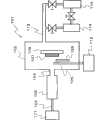
关于该反应装置1,在可以减压的反应室2内配置有:具有与H2O气体原料供给部11连接的H2O气体原料导入口3和反应气体(H2O气体)喷出喷嘴4的催化反应装置5、以及与成为薄膜原料的有机金属化合物气体供给部12连接的有机金属化合物气体导入喷嘴6和对基板7进行支承的基板托架8。反应室2借助排气管13与涡轮分子泵14和回转泵15连接。In this reaction device 1, an H2 O gas
催化反应装置5例如为如下结构,在由不锈钢等金属构成的圆筒状催化容器套筒21内,收纳由陶瓷或金属等材料构成的催化反应容器22,并利用喷射喷嘴4将催化容器套筒21封闭。The
在催化反应容器22内配置有在微粒状的载体上担载有超微粒状的催化剂成分而得到的催化剂(未图示)。催化反应容器22的一个端部借助H2O气体原料导入口3与H2O气体原料供给部11连接,另一个端部配置有用于堵住催化剂的金属网23。A catalyst (not shown) in which an ultrafine particle catalyst component is supported on a fine particle carrier is arranged in the
另外,图3表示配置有在微粒状的载体上担载有超微粒状的催化剂成分而得到的催化剂的结构。具体而言,催化反应装置5例如为如下结构,在由不锈钢等金属构成的圆筒状的催化容器套筒21内,收纳由陶瓷或金属等材料构成的催化反应容器22,并利用喷射喷嘴4将催化容器套筒21封闭。In addition, FIG. 3 shows a structure in which a catalyst in which an ultrafine particle catalyst component is supported on a fine particle carrier is arranged. Specifically, the
在催化反应容器22内,配置有在微粒状的载体上担载有超微粒状的催化剂成分而得到的催化剂25。催化反应容器22的一个端部借助H2O气体原料导入口3与H2O气体原料供给部11连接,另一个端部配置有用于堵住催化剂的金属网23。In the
在该催化反应装置5内,从与H2O气体原料供给部11连接的H2O气体原料导入口3导入由H2气体和O2气体的混合气体、或者由H2O2气体构成的H2O气体原料时,利用微粒状的催化剂进行H2气体和O2气体的化合反应或者H2O2气体的分解反应。这些反应伴随着大量放热,利用该反应热而被加热到高温的H2O气体,从反应气体喷出喷嘴4猛烈地喷向由基板托架8保持的基板7。该喷出H2O气体与从有机金属化合物气体导入喷嘴6供给的有机金属化合物气体发生反应,得到金属氧化物气体24,从而在基板7的表面沉积金属氧化物薄膜,所述有机金属化合物气体导入喷嘴6与有机金属化合物气体供给部12连接。In this
需要说明的是,在催化反应装置5和基板7之间设置可以开关的开闭器(未图示),在反应初期关闭开闭器从而阻断副产物气体。当采用这种构成时,可以在基板7上形成具有更均匀性状的金属氧化物薄膜。It should be noted that a switchable switch (not shown) is provided between the
作为在基板表面形成的氧化物,没有特别限制,但作为优选的氧化物,可以举出氧化钛、氧化锌、氧化镁、氧化钇、蓝宝石、Sn:In2O3(ITO:氧化铟锡)等金属氧化物。The oxide formed on the surface of the substrate is not particularly limited, but examples of preferred oxides include titanium oxide, zinc oxide, magnesium oxide, yttrium oxide, sapphire, and Sn:In2 O3 (ITO: indium tin oxide) and other metal oxides.
对成为金属氧化物薄膜原料的有机金属化合物气体没有特别限制,例如利用以往的CVD法形成金属氧化物时使用的有机金属化合物气体均可以使用。作为这种有机金属化合物,可以举出例如各种金属的烷基化合物、烯基化合物、苯基或烷基苯基化合物、醇盐化合物、二叔戊酰甲烷化合物、卤素化合物、乙酰乙酸酯化合物、EDTA化合物等。另外,成为金属氧化物薄膜原料的物质除了有机金属化合物气体以外,还可以是卤素化合物等无机金属化合物气体。作为具体例,可以举出氯化锌(ZnCl2)等。The organometallic compound gas used as the raw material of the metal oxide thin film is not particularly limited, and for example, any organometallic compound gas used for forming a metal oxide by a conventional CVD method can be used. Such organometallic compounds include, for example, alkyl compounds, alkenyl compounds, phenyl or alkylphenyl compounds, alkoxide compounds, di-tert-valerylmethane compounds, halogen compounds, acetoacetates, etc., of various metals. compounds, EDTA compounds, etc. In addition, the substance used as the raw material of the metal oxide thin film may be an inorganic metal compound gas such as a halogen compound in addition to the organic metal compound gas. Specific examples include zinc chloride (ZnCl2 ) and the like.
作为优选的有机金属化合物,可以举出各种金属的烷基化合物、金属醇盐。具体而言,可以举出二甲基锌、二乙基锌、三甲基铝、三乙基铝、三甲基铟、三乙基铟、三甲基镓、三乙基镓、三乙氧基铝等。Examples of preferable organometallic compounds include alkyl compounds and metal alkoxides of various metals. Specifically, dimethylzinc, diethylzinc, trimethylaluminum, triethylaluminum, trimethylindium, triethylindium, trimethylgallium, triethylgallium, triethoxy base aluminum etc.
在基板表面形成氧化锌薄膜时,优选以二甲基锌、二乙基锌等二烷基锌为原料,使用在微粒状的氧化铝上担载有铂超微粒子而得到的催化剂。When forming the zinc oxide thin film on the surface of the substrate, it is preferable to use a catalyst in which platinum ultrafine particles are supported on particulate alumina using dialkyl zinc such as dimethyl zinc or diethyl zinc as a raw material.
作为基板,可以使用例如从金属、金属氧化物、玻璃、陶瓷、半导体、塑料中选择的基板。As the substrate, for example, a substrate selected from metals, metal oxides, glass, ceramics, semiconductors, and plastics can be used.
作为优选的基板,可以举出以蓝宝石等为代表的化合物单晶基板、以Si等为代表的单晶基板、以玻璃为代表的非晶质基板、聚酰亚胺等工程塑料基板等。Preferable substrates include compound single crystal substrates such as sapphire, single crystal substrates such as Si, amorphous substrates such as glass, and engineering plastic substrates such as polyimide.
在本发明中,通过在催化反应装置5内导入成为金属氧化物薄膜的氧源的H2气体和O2气体的混合气体或者H2O2气体,使其与微粒状的催化剂接触而得到高能量的H2O气体,使该H2O气体从催化反应装置中喷出而与有机金属化合物气体反应,由此在无需大量电能的情况下,可以以低成本在各种基板上高效地形成金属氧化物薄膜。这样伴有大量放热的化学反应,通过选择特定的气体作为氧源,并使用微粒状的催化剂,从而能够首次得以实现。另外,载体的形状可以是海绵状等具有许多孔的形状、蜂窝状等具有贯通孔的形状等松散形状。此外,在载体上担载的铂、钌、铱、铜等催化物质的形状不限于微粒状,例如也可以是膜状。这是由于,具体而言,如果增加催化物质的表面积,则可以获得本实施方式的效果,例如,如果在上述载体的表面形成催化物质的膜,则可以增加催化物质的表面积,并且能获得与微粒状的情况同样的效果。In the present invention, a mixed gas of H2 gas and O2 gas or H2 O2 gas, which is the oxygen source of the metal oxide thin film, is introduced into the
对于本发明的方法,由于无需将基板加热到高温,因此即使在对于以往的热CVD法而言无法实现的400℃以下的低温下,仍可以在基板上形成高品质的异质外延膜。因此,可以使用以往技术中难以实现的基板,以低成本制造出半导体材料、各种电子材料等。Since the method of the present invention does not need to heat the substrate to a high temperature, a high-quality heteroepitaxial film can be formed on the substrate even at a low temperature of 400° C. or lower, which cannot be achieved by conventional thermal CVD methods. Therefore, it is possible to manufacture semiconductor materials, various electronic materials, etc. at low cost using substrates that were difficult to realize in conventional technologies.
另外,图4示出本实施方式中的其他金属氧化物薄膜的制造装置的构成。具体而言,催化反应装置设于反应室外,且与反应室连接。即,关于该反应装置101,催化反应装置105以反应气体(H2O气体)喷出喷嘴104与可以减压的反应室102连接,而且在可以减压的反应室102内,配置有与成为薄膜原料的有机金属化合物气体供给部112连接的有机金属化合物气体导入喷嘴106和对基板107进行支承的基板托架108,所述催化反应装置105具有与H2O气体原料供给部111连接的H2O气体原料导入口103和反应气体(H2O气体)喷出喷嘴104。反应室102借助排气管113与涡轮分子泵114和回转泵115连接。In addition, FIG. 4 shows the configuration of another metal oxide thin film manufacturing apparatus in this embodiment. Specifically, the catalytic reaction device is arranged outside the reaction chamber and connected with the reaction chamber. That is, with regard to the
另外,在催化反应装置105和基板107之间设置可以开关的开闭器126(在图中示出已打开的状态),可以在反应初期关闭开闭器从而阻断副产物气体。当采用这种构成时,可以在基板107上形成具有更均匀性状的金属氧化物薄膜。In addition, a switchable shutter 126 (opened state is shown in the figure) is provided between the
[第二实施方式][Second Embodiment]
对本发明的第二实施方式进行说明。关于本实施方式,通过向催化反应装置内分别导入H2气体和O2气体,在催化反应装置内使其与微粒状的催化剂反应,从而产生利用反应热而被加热到高温的H2O气体,使该H2O气体从喷出喷嘴喷出,使之与成为薄膜材料的有机金属化合物气体混合、反应,由此在基板表面形成金属氧化物薄膜。这样,通过分别导入,具有能够防止因H2气体与O2气体的反应而有可能会产生的逆火(在催化反应装置内生成H2O气体时产生的火焰点燃经催化反应装置而流向上游的H2O气体原料)的效果。A second embodiment of the present invention will be described. In this embodiment, H2 gas and O2 gas are separately introduced into the catalytic reaction device, and react with a particulate catalyst in the catalytic reaction device to generate H2 O gas heated to a high temperature by the reaction heat. , the H2 O gas is ejected from the ejection nozzle to mix and react with the organometallic compound gas used as the thin film material, thereby forming a metal oxide thin film on the surface of the substrate. In this way, by introducing them separately, it is possible to prevent backfire that may occur due to the reaction of H2 gas and O2 gas (the flame ignited when H2 O gas is generated in the catalytic reaction device and flows upstream through the catalytic reaction device. H2 O gas feedstock) effect.
作为收纳于催化反应装置中的催化剂,可以使用在平均粒径0.05~2.0mm的微粒状载体上担载有平均粒径1~10nm的超微粒状的催化剂成分而得到的催化剂或者平均粒径0.1mm~0.5mm左右的铂、钌、铱、铜等的金属粉末等。作为载体,可以使用氧化铝、氧化锆、氧化锌等金属氧化物的微粒,即,可以使用氧化物陶瓷的微粒。作为优选的催化剂,可以举出例如在氧化铝载体上担载有铂纳米粒子而得到的催化剂,尤其是在对多孔γ-氧化铝于500~1200℃进行加热处理后,在维持了其表面结构的状态下转换成α-氧化铝结晶相的载体上担载1~20重量%左右的铂而得到的催化剂(例如10wt%Pt/γ-Al2O3催化剂)等。As the catalyst contained in the catalytic reaction device, a catalyst obtained by loading an ultrafine catalyst component with an average particle diameter of 1 to 10 nm on a particulate carrier with an average particle diameter of 0.05 to 2.0 mm or a catalyst with an average particle diameter of 0.1 mm can be used. Metal powders such as platinum, ruthenium, iridium, copper, etc. about mm to 0.5mm. As the carrier, fine particles of metal oxides such as alumina, zirconia, and zinc oxide, that is, fine particles of oxide ceramics can be used. As a preferred catalyst, for example, a catalyst obtained by supporting platinum nanoparticles on an alumina carrier, especially after heat-treating porous γ-alumina at 500 to 1200°C, the surface structure is maintained A catalyst obtained by loading about 1 to 20% by weight of platinum on a carrier converted into an α-alumina crystal phase in a state of α-alumina (for example, a 10wt% Pt/γ-Al2 O3 catalyst), and the like.
接下来,参照附图对本发明的优选方式进行说明,但是本发明不限于以下的具体例。Next, preferred embodiments of the present invention will be described with reference to the drawings, but the present invention is not limited to the following specific examples.
图5和图6是表示在本实施方式中在各种基板上形成金属氧化物薄膜时使用的装置的一例的示意图,图5是装置整体的构成图,而图6是在该装置内配置的催化反应装置的放大示意图。5 and 6 are schematic diagrams showing an example of an apparatus used when forming a metal oxide thin film on various substrates in this embodiment, FIG. 5 is a configuration diagram of the entire apparatus, and FIG. An enlarged schematic diagram of the catalytic reaction setup.
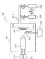
该反应装置201中的可以减压的反应室202,与H2气体供给部210和O2气体供给部211连接,H2气体供给部210借助H2气体导入口203与催化反应装置205连接,O2气体供给部211借助O2气体导入口213与催化反应装置205连接。该催化反应装置205具有反应气体(H2O气体)喷出喷嘴204。The
此外,在可以减压的反应室202内配置有与成为薄膜原料的有机金属化合物气体供给部212连接的有机金属化合物气体导入喷嘴206和用于支承基板207的基板托架208。反应室202借助排气管213与涡轮分子泵214和回转泵215连接。In addition, an organometallic compound
催化反应装置205例如为如下结构,在由不锈钢等金属构成的圆筒状的催化容器套筒221内,收纳由陶瓷或金属等材料构成的催化反应容器222,并利用喷射喷嘴204将催化容器套筒221封闭。The
催化反应容器222内配置有在微粒状的载体上担载有超微粒状的催化剂成分而得到的催化剂225。催化反应容器222的一个端部,借助H2气体导入口203和O2气体导入口213,分别与H2气体供给部210和O2气体供给部211连接,另一个端部配置有用于堵住催化剂的金属网223。A
在该催化反应装置205内,利用与H2气体供给部210连接的H2气体导入口203和与O2气体供给部211连接的O2气体导入口213,导入H2气体和O2气体。由此,利用微粒状的催化剂进行H2气体和O2气体的化合反应。这些反应伴随着大量放热,利用该反应热而被加热到高温的H2O气体,从反应气体喷出喷嘴204猛烈地喷向由基板托架208保持的基板207。该喷出H2O气体与从有机金属化合物气体导入喷嘴206供给的有机金属化合物气体反应,得到金属氧化物气体224,从而在基板207的表面沉积金属氧化物薄膜,所述有机金属化合物气体导入喷嘴206与有机金属化合物气体供给部212连接。In this
需要说明的是,在催化反应装置205和基板207之间设置可以开关的开闭器226(在图中示出已打开的状态),可以在反应初期关闭开闭器从而阻断副产物气体(在成膜工艺达到稳定进行的状态之前的阶段从催化反应装置205向基板207喷出的不适合膜沉积的气体)。当采用这种构成时,可以在基板207上形成具有更均匀性状的金属氧化物薄膜。It should be noted that between the
作为在基板表面形成的氧化物,没有特别限制,但作为优选的氧化物,可以举出氧化钛、氧化锌、氧化镁、氧化钇、蓝宝石、Sn:In2O3(ITO:氧化铟锡)等金属氧化物。The oxide formed on the surface of the substrate is not particularly limited, but examples of preferred oxides include titanium oxide, zinc oxide, magnesium oxide, yttrium oxide, sapphire, and Sn:In2 O3 (ITO: indium tin oxide) and other metal oxides.
对成为金属氧化物薄膜原料的有机金属化合物气体没有特别限制,例如利用以往的CVD法形成金属氧化物时使用的有机金属化合物气体,均可以使用。作为这种有机金属化合物,可以举出例如各种金属的烷基化合物、烯基化合物、苯基或烷基苯基化合物、醇盐化合物、二叔戊酰甲烷化合物、卤素化合物、乙酰乙酸酯化合物、EDTA化合物等。另外,成为金属氧化物薄膜原料的物质,除了有机金属化合物气体以外,还可以是卤素化合物等无机金属化合物气体。作为具体例,可以举出氯化锌(ZnCl2)等。The organometallic compound gas used as the raw material of the metal oxide thin film is not particularly limited, and any organometallic compound gas used for forming a metal oxide by a conventional CVD method can be used. Such organometallic compounds include, for example, alkyl compounds, alkenyl compounds, phenyl or alkylphenyl compounds, alkoxide compounds, di-tert-valerylmethane compounds, halogen compounds, acetoacetates, etc., of various metals. compounds, EDTA compounds, etc. In addition, the substance used as the raw material of the metal oxide thin film may be an inorganic metal compound gas such as a halogen compound in addition to the organic metal compound gas. Specific examples include zinc chloride (ZnCl2 ) and the like.
作为优选的有机金属化合物,可以举出各种金属的烷基化合物、金属醇盐。具体而言,可以举出二甲基锌、二乙基锌、三甲基铝、三乙基铝、三甲基铟、三乙基铟、三甲基镓、三乙基镓、三乙氧基铝等。Examples of preferable organometallic compounds include alkyl compounds and metal alkoxides of various metals. Specifically, dimethylzinc, diethylzinc, trimethylaluminum, triethylaluminum, trimethylindium, triethylindium, trimethylgallium, triethylgallium, triethoxy base aluminum etc.
在基板表面形成氧化锌薄膜时,优选以二甲基锌、二乙基锌等二烷基锌为原料,使用在微粒状的氧化铝上担载有铂超微粒子而得到的催化剂。When forming the zinc oxide thin film on the surface of the substrate, it is preferable to use a catalyst in which platinum ultrafine particles are supported on particulate alumina using dialkyl zinc such as dimethyl zinc or diethyl zinc as a raw material.
作为基板,可以使用例如从金属、金属氧化物、玻璃、陶瓷、半导体、塑料中选择的基板。As the substrate, for example, a substrate selected from metals, metal oxides, glass, ceramics, semiconductors, and plastics can be used.
作为优选的基板,可以举出以蓝宝石等为代表的化合物单晶基板、以Si等为代表的单晶基板、以玻璃为代表的非晶质基板、聚酰亚胺等工程塑料基板等。Preferable substrates include compound single crystal substrates such as sapphire, single crystal substrates such as Si, amorphous substrates such as glass, and engineering plastic substrates such as polyimide.
在本实施方式中,如上所述,向催化反应装置205内导入成为金属氧化物薄膜的氧源的H2气体和O2气体,使其与微粒状的催化剂接触而得到高能量的H2O气体,使该H2O气体从催化反应装置中喷出而与有机金属化合物气体反应,由此在无需大量电能的情况下,可以以低成本在各种基板上高效地形成金属氧化物薄膜。这样伴有大量放热的化学反应,通过选择特定的气体作为氧源,并使用微粒状的催化剂,从而能够首次得以实现。另外,载体的形状可以是海绵状等具有许多孔的形状、蜂窝状等具有贯通孔的形状等松散形状。此外,在载体上担载的铂、钌、铱、铜等催化物质的形状不限于微粒状,例如也可以是膜状。这是由于,具体而言,如果增加催化物质的表面积,则可以获得本实施方式的效果,例如,如果在上述载体的表面形成了催化物质的膜,则可以增加催化物质的表面积,能获得与微粒状的情况同样的效果。In the present embodiment, as described above, H2 gas and O2 gas, which are oxygen sources for the metal oxide thin film, are introduced into the
对于本发明的方法,由于无需将基板加热到高温,因此即使在对于以往的热CVD法而言无法实现的400℃以下的低温下,仍可以在基板上形成高品质的异质外延膜。因此,可以使用以往技术中难以实现的基板,以低成本制造出半导体材料、各种电子材料等。Since the method of the present invention does not need to heat the substrate to a high temperature, a high-quality heteroepitaxial film can be formed on the substrate even at a low temperature of 400° C. or lower, which cannot be achieved by conventional thermal CVD methods. Therefore, it is possible to manufacture semiconductor materials, various electronic materials, etc. at low cost using substrates that were difficult to realize in conventional technologies.
另外,关于本实施方式中的催化反应装置205,其与H2气体导入口203及O2气体导入口213的连接方法,除了像如上述中说明的图6所示,由与反应气体喷出喷嘴204相面对的位置导入的结构以外,还考虑到其他的结构例。具体而言有下面的结构,如图7所示,H2气体导入口203和O2气体导入口213中的一个导入口从与反应气体喷出喷嘴204相面对的位置导入,另一个导入口从成为催化反应装置205侧面的位置导入的结构;或者如图8所示,H2气体导入口203和O2气体导入口213均从成为催化反应装置205侧面的位置导入的结构。In addition, regarding the
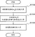
接着,根据图9,对本实施方式中的金属氧化物薄膜的成膜工艺进行更加详细的说明。Next, the film formation process of the metal oxide thin film in this embodiment will be described in more detail with reference to FIG. 9 .
最开始如步骤102(S102)所示,由H2气体供给部210和O2气体供给部211借助H2气体导入口203和O2气体导入口213,将H2气体和O2气体导入到催化反应装置205内。由此,利用催化反应装置205内的微粒状催化剂使H2气体和O2气体进行化合反应。具体而言,利用反应2H2+O2→2H2O而生成H2O。该反应伴随着大量放热,被该反应热加热的高温H2O气体,从反应气体喷出喷嘴204猛烈地喷向由基板托架208保持的基板207。Initially,as showninstep 102 (S102), H2 gas andO2 gas are introduced into Inside the
接着,如步骤104(S104)所示,H2O气体和有机金属化合物气体发生化学反应,而生成金属氧化物气体224。即,由反应气体喷出喷嘴204喷出的H2O与从有机金属化合物气体导入喷嘴206供给的有机金属化合物气体发生化学反应,而生成金属氧化物气体224。具体而言,利用例如反应Zn(CH3)2+H2O→ZnO+2CH4,而生成金属氧化物气体224。另外,通过改变导入的有机金属化合物气体的材料,例如利用反应Zn(CH2CH3)2+H2O→ZnO+2C2H6,而生成金属氧化物气体224。Next, as shown in step 104 ( S104 ), the H2 O gas and the organometallic compound gas react chemically to generate the
接着,如工序步骤106(S106)所示,生成的金属氧化物224在基板207的表面以金属氧化物薄膜沉积。Next, as shown in process step 106 ( S106 ), the generated
根据这样的工序,进行金属氧化物薄膜的成膜。According to such steps, the metal oxide thin film is formed.
实施例Example
接下来,利用实施例对本发明进行进一步的说明,但是以下具体例并不限定本发明。在以下的例子中,使用第一实施方式中的图1的反应装置,在蓝宝石基板上形成氧化锌薄膜。Next, the present invention will be further described using examples, but the following specific examples do not limit the present invention. In the following example, a zinc oxide thin film was formed on a sapphire substrate using the reaction apparatus shown in FIG. 1 in the first embodiment.
(实施例1)(Example 1)
在平均粒径0.3mm的γ-Al2O3载体1.0g中浸渗担载氯铂(IV)酸六水合物0.27g后,在空气中450℃下煅烧4小时,由此得到10wt%Pt/γ-Al2O3催化剂。在催化反应容器22中填充0.27g的平均粒径0.3mm的γ-Al2O3后,填充0.02g的10wt%Pt/γ-Al2O3催化剂,在设置金属网23后,设置喷射喷嘴4,构成催化反应装置5,设置于能减压的反应室2内。After impregnating 0.27 g of supported chloroplatinum (IV) acid hexahydrate in 1.0 g of γ-Al2 O3 carrier with an average particle size of 0.3 mm, it was calcined at 450° C. in air for 4 hours, thereby obtaining 10 wt % Pt /γ-Al2 O3 catalyst. After filling 0.27g of γ-Al2 O3 with an average particle diameter of 0.3mm in the
向本构成的催化反应装置5内导入0.06气压的H2、0.06气压的O2,在催化剂表面使这些H2和O2燃烧,在催化反应部生成达1000℃的H2O气体。在关闭设置于喷射喷嘴4前面的开闭器的状态下,使该高温H2O气体从喷射喷嘴4喷出。0.06 atmospheric pressure of H2 and 0.06 atmospheric pressure of O2 are introduced into the
另一方面,从有机金属化合物气体供给部12将成为ZnO原料的二乙基锌1×10⁻⁵Torr借助有机金属化合物气体导入喷嘴6导入到反应室2内,使其与上述的高温H2O气体接触而形成ZnO前体。在反应室2内由基板托架8支承的表面温度400℃的C轴取向蓝宝石基板7(尺寸10mm×10mm)的表面上,通过打开上述的开闭器,使ZnO前体沉积,而得到ZnO薄膜。在本实施例中,将沉积时间设为20分钟。沉积的结果是得到的ZnO薄膜的膜厚是2μm。将对得到的ZnO薄膜进行测定而得到的XRD图案示于图10,将荧光光谱示于图11。此外,ZnO薄膜的电特性和沉积速度如下所示。On the other hand, 1×10⁻⁵ Torr of diethylzinc, which is a raw material of ZnO, is introduced from the organometallic compound
蓝宝石基板温度:400℃Sapphire substrate temperature: 400°C
载流子的移动速度:38.4cm2/VsCarrier moving speed: 38.4cm2 /Vs
载流子密度:4.79×1018cm-3Carrier density: 4.79×1018 cm-3
电阻率:5.09×10⁻²ΩcmResistivity: 5.09×10⁻² Ωcm
ZnO薄膜沉积速度:330nm/minZnO film deposition speed: 330nm/min
在上述实施例中,使用H2和O2的混合气体作为H2O气体原料,但也可以使用H2O2气体来代替上述混合气体。此外,使用Zn以外的其他金属化合物气体作为有机金属化合物气体,在使用其他基板时也同样能高效地在基板上形成金属氧化物薄膜。In the above embodiments, the mixed gas of H2 and O2 is used as the raw material of H2 O gas, but H2 O2 gas may be used instead of the above mixed gas. In addition, by using a metal compound gas other than Zn as the organometallic compound gas, it is possible to efficiently form a metal oxide thin film on a substrate in the same manner when other substrates are used.
在本发明中,向催化反应装置5内导入成为金属氧化物薄膜的氧源的H2气体和O2气体的混合气体或者H2O2气体,使其与微粒状的催化剂接触从而得到高能量的H2O气体,使该H2O气体从催化反应装置中喷出而与有机金属化合物气体反应,由此在无需大量电能的情况下,可以以低成本在基板上高效地形成金属氧化物薄膜。In the present invention, a mixed gas of H2 gas and O2 gas or H2 O2 gas, which is the oxygen source of the metal oxide thin film, is introduced into the
工业上的可用性industrial availability
本发明通过使氧化锌等金属氧化物沉积在基板上,可以应用于形成作为半导体材料等有用的金属氧化物薄膜的技术。The present invention can be applied to a technique for forming a metal oxide thin film useful as a semiconductor material or the like by depositing a metal oxide such as zinc oxide on a substrate.
以上利用实施例对本发明进行了说明,但本发明不限于上述实施例,当然可以在本发明的范围内进行各种变形和改良。As mentioned above, although this invention was demonstrated using an Example, this invention is not limited to the said Example, Of course, various deformation|transformation and improvement are possible within the range of this invention.
本申请是基于2007年5月22日申请的日本专利申请第2007-135817号,在此援引其全部内容。This application is based on Japanese Patent Application No. 2007-135817 filed on May 22, 2007, the entire contents of which are incorporated herein.
Claims (19)
Translated fromChineseApplications Claiming Priority (3)
| Application Number | Priority Date | Filing Date | Title |
|---|---|---|---|
| JP2007135817 | 2007-05-22 | ||
| JP135817/2007 | 2007-05-22 | ||
| PCT/JP2008/059087WO2008143197A1 (en) | 2007-05-22 | 2008-05-16 | Method and apparatus for production of metal oxide thin film |
Publications (2)
| Publication Number | Publication Date |
|---|---|
| CN101680088Atrue CN101680088A (en) | 2010-03-24 |
| CN101680088B CN101680088B (en) | 2013-01-02 |
Family
ID=40031896
Family Applications (1)
| Application Number | Title | Priority Date | Filing Date |
|---|---|---|---|
| CN2008800154318AExpired - Fee RelatedCN101680088B (en) | 2007-05-22 | 2008-05-16 | Method and apparatus for production of metal oxide thin film |
Country Status (7)
| Country | Link |
|---|---|
| US (1) | US8591991B2 (en) |
| JP (1) | JP5496471B2 (en) |
| KR (1) | KR20100010929A (en) |
| CN (1) | CN101680088B (en) |
| DE (1) | DE112008001372T5 (en) |
| TW (1) | TW200912029A (en) |
| WO (1) | WO2008143197A1 (en) |
Cited By (2)
| Publication number | Priority date | Publication date | Assignee | Title |
|---|---|---|---|---|
| CN107531504A (en)* | 2015-05-19 | 2018-01-02 | 东曹精细化工株式会社 | The manufacture method of solution containing dialkyl group zinc partial hydrolystate and the zinc-oxide film using the solution |
| CN109402608A (en)* | 2017-08-16 | 2019-03-01 | 北京北方华创微电子装备有限公司 | A kind of air-channel system and its control method of atomic layer deposition apparatus |
Families Citing this family (1)
| Publication number | Priority date | Publication date | Assignee | Title |
|---|---|---|---|---|
| JP7162297B2 (en)* | 2018-08-08 | 2022-10-28 | キレスト株式会社 | Method for producing composite in which metal oxide is immobilized on carbon substrate |
Family Cites Families (23)
| Publication number | Priority date | Publication date | Assignee | Title |
|---|---|---|---|---|
| US475149A (en)* | 1892-05-17 | Stovepipe attachment | ||
| JPS57127446A (en) | 1981-01-29 | 1982-08-07 | Mitsui Mining & Smelting Co Ltd | Catalyst for gas purification |
| JPH0682625B2 (en)* | 1985-06-04 | 1994-10-19 | シーメンス ソーラー インダストリーズ,エル.ピー. | Deposition method of zinc oxide film |
| US4928627A (en)* | 1985-12-23 | 1990-05-29 | Atochem North America, Inc. | Apparatus for coating a substrate |
| JP2545306B2 (en)* | 1991-03-11 | 1996-10-16 | 誠 小長井 | Method for producing ZnO transparent conductive film |
| JPH06128743A (en) | 1992-09-04 | 1994-05-10 | Mitsubishi Materials Corp | Transparent electrically conductive film, production and target used therefor |
| US5985691A (en)* | 1997-05-16 | 1999-11-16 | International Solar Electric Technology, Inc. | Method of making compound semiconductor films and making related electronic devices |
| JPH1111903A (en)* | 1997-06-20 | 1999-01-19 | Permelec Electrode Ltd | Production of light water |
| JP4237861B2 (en) | 1999-03-30 | 2009-03-11 | Hoya株式会社 | Highly monocrystalline zinc oxide thin film and manufacturing method |
| ES2292494T3 (en)* | 1999-12-23 | 2008-03-16 | Dow Global Technologies Inc. | CATALYZING DEVICES. |
| JP2001262354A (en)* | 2000-03-14 | 2001-09-26 | Ebara Corp | Film deposition system |
| KR100406174B1 (en)* | 2000-06-15 | 2003-11-19 | 주식회사 하이닉스반도체 | Showerhead used chemically enhanced chemical vapor deposition equipment |
| US6713177B2 (en)* | 2000-06-21 | 2004-03-30 | Regents Of The University Of Colorado | Insulating and functionalizing fine metal-containing particles with conformal ultra-thin films |
| EP1172856A1 (en)* | 2000-07-03 | 2002-01-16 | Matsushita Electric Industrial Co., Ltd. | Nonvolatile semiconductor memory device and method for fabricating the same |
| JP2002100621A (en) | 2000-09-20 | 2002-04-05 | Seiko Epson Corp | Film forming apparatus, film forming method, substrate formed by this, and liquid crystal device using this substrate |
| US20030044539A1 (en)* | 2001-02-06 | 2003-03-06 | Oswald Robert S. | Process for producing photovoltaic devices |
| JP2004071757A (en) | 2002-08-05 | 2004-03-04 | Hitachi Ltd | Method and apparatus for manufacturing high dielectric constant film |
| JP3561745B1 (en) | 2003-02-11 | 2004-09-02 | 関西ティー・エル・オー株式会社 | Thin film manufacturing method |
| US20050252449A1 (en)* | 2004-05-12 | 2005-11-17 | Nguyen Son T | Control of gas flow and delivery to suppress the formation of particles in an MOCVD/ALD system |
| US20060062917A1 (en)* | 2004-05-21 | 2006-03-23 | Shankar Muthukrishnan | Vapor deposition of hafnium silicate materials with tris(dimethylamino)silane |
| JP2006116372A (en)* | 2004-10-19 | 2006-05-11 | Seimi Chem Co Ltd | Carbon monoxide selective oxidation catalyst |
| JP2007135817A (en) | 2005-11-17 | 2007-06-07 | Tomy Co Ltd | Sphere launch toy |
| JP6082625B2 (en)* | 2013-03-11 | 2017-02-15 | 日新製鋼株式会社 | Stainless steel strip manufacturing method |
- 2008
- 2008-05-16WOPCT/JP2008/059087patent/WO2008143197A1/enactiveApplication Filing
- 2008-05-16CNCN2008800154318Apatent/CN101680088B/ennot_activeExpired - Fee Related
- 2008-05-16USUS12/600,665patent/US8591991B2/ennot_activeExpired - Fee Related
- 2008-05-16DEDE112008001372Tpatent/DE112008001372T5/ennot_activeWithdrawn
- 2008-05-16KRKR1020097025826Apatent/KR20100010929A/ennot_activeCeased
- 2008-05-20JPJP2008132193Apatent/JP5496471B2/ennot_activeExpired - Fee Related
- 2008-05-21TWTW097118706Apatent/TW200912029A/enunknown
Cited By (3)
| Publication number | Priority date | Publication date | Assignee | Title |
|---|---|---|---|---|
| CN107531504A (en)* | 2015-05-19 | 2018-01-02 | 东曹精细化工株式会社 | The manufacture method of solution containing dialkyl group zinc partial hydrolystate and the zinc-oxide film using the solution |
| CN109402608A (en)* | 2017-08-16 | 2019-03-01 | 北京北方华创微电子装备有限公司 | A kind of air-channel system and its control method of atomic layer deposition apparatus |
| CN109402608B (en)* | 2017-08-16 | 2020-12-08 | 北京北方华创微电子装备有限公司 | Gas path system of atomic layer deposition equipment and control method thereof |
Also Published As
| Publication number | Publication date |
|---|---|
| KR20100010929A (en) | 2010-02-02 |
| US20100166958A1 (en) | 2010-07-01 |
| JP5496471B2 (en) | 2014-05-21 |
| TW200912029A (en) | 2009-03-16 |
| DE112008001372T5 (en) | 2010-04-15 |
| JP2009001899A (en) | 2009-01-08 |
| US8591991B2 (en) | 2013-11-26 |
| CN101680088B (en) | 2013-01-02 |
| WO2008143197A1 (en) | 2008-11-27 |
Similar Documents
| Publication | Publication Date | Title |
|---|---|---|
| JP5400795B2 (en) | Substrate processing method and substrate processing apparatus | |
| JP5408819B2 (en) | Deposition apparatus and deposition method | |
| KR101272872B1 (en) | Substrate processing apparatus | |
| EP1886801A1 (en) | Thin film forming method and transparent conductive film | |
| CN101680088A (en) | Manufacturing method and manufacturing apparatus of metal oxide thin film | |
| JP5057523B2 (en) | Method of depositing nitride film | |
| Matsuzaki et al. | Growth of yttria stabilized zirconia thin films by metallo-organic, ultrasonic spray pyrolysis | |
| Sanchez-Perez et al. | Self-textured ZnO via AACVD of alkyl alkoxides: a solution-based seed-less route towards optoelectronic-grade coatings | |
| Hsu et al. | Deposition of ZnO thin films by an atmospheric pressure plasma jet-assisted process: The selection of precursors | |
| JP2011178635A (en) | Film deposition apparatus, system and film deposition method | |
| JP5157096B2 (en) | Transparent conductive film forming method and transparent conductive film | |
| JP4327405B2 (en) | Method for producing electrode for solid electrolyte | |
| Tucić et al. | Synthesis of thin films by the pyrosol process | |
| JP2013119662A (en) | Film forming apparatus | |
| JP2004225123A (en) | Method for depositing oxide film on surface of base material, and apparatus used for the method | |
| Aleksandar | Synthesis of thin films by the pyrosol process | |
| MARINKOVIĆ et al. | SYNTHESIS OF THIN FILMS BY THE PYROSOL PROCESS | |
| GB2308132A (en) | Depositing films on a substrate using an electric field | |
| JP2009186482A (en) | Electrode for solid electrolyte and method for producing the same |
Legal Events
| Date | Code | Title | Description |
|---|---|---|---|
| C06 | Publication | ||
| PB01 | Publication | ||
| C10 | Entry into substantive examination | ||
| SE01 | Entry into force of request for substantive examination | ||
| C14 | Grant of patent or utility model | ||
| GR01 | Patent grant | ||
| CF01 | Termination of patent right due to non-payment of annual fee | Granted publication date:20130102 Termination date:20150516 | |
| EXPY | Termination of patent right or utility model |