CN101677154B - Electric connector - Google Patents
Electric connectorDownload PDFInfo
- Publication number
- CN101677154B CN101677154BCN2008101967030ACN200810196703ACN101677154BCN 101677154 BCN101677154 BCN 101677154BCN 2008101967030 ACN2008101967030 ACN 2008101967030ACN 200810196703 ACN200810196703 ACN 200810196703ACN 101677154 BCN101677154 BCN 101677154B
- Authority
- CN
- China
- Prior art keywords
- electrical connector
- insulating body
- contact
- arm
- contact arm
- Prior art date
- Legal status (The legal status is an assumption and is not a legal conclusion. Google has not performed a legal analysis and makes no representation as to the accuracy of the status listed.)
- Expired - Fee Related
Links
Images

Landscapes
- Coupling Device And Connection With Printed Circuit (AREA)
Abstract
Translated fromChinese
Description
Translated fromChinese【技术领域】【Technical field】
本发明涉及一种电连接器,尤其涉及一种连接于印刷电路板上的电连接器。The invention relates to an electrical connector, in particular to an electrical connector connected to a printed circuit board.
【背景技术】【Background technique】
请参阅美国专利公告第7,278,861号,其揭示了一种插座及插头连接器组件,该插座连接器包括有绝缘本体、固持于绝缘本体上的数个端子;所述绝缘本体具有对接空间及形成对接空间的侧壁,且侧壁之间形成有凸伸入对接空间的舌板,绝缘本体形成有收容端子的收容槽,该槽道贯穿绝缘本体的底侧;所述端子设有位于侧壁一侧的第一接触臂及与该第一接触臂相对设置并位于舌板一侧的第二接触臂,该第二接触臂是自所述收容槽内向对接空间凸伸,由于该收容槽内设有挡止第二接触臂的挡止壁,可防止两连接器对接时,该第二接触臂被插头连接器的端子带出,影响再次对接的对接效果;目前电连接器向低构型的趋势发展,当端子的高度一定时,需通过减小上述挡止壁的厚度以符合低构型的发展趋势,然而,这种改善措施会减小该挡止壁的强度,绝缘本体易被端子挤压而破坏,从而影响电连接器的使用性能。Please refer to U.S. Patent No. 7,278,861, which discloses a receptacle and plug connector assembly, the receptacle connector includes an insulating body, and several terminals held on the insulating body; the insulating body has a docking space and forms a docking The side wall of the space, and a tongue plate protruding into the docking space is formed between the side walls, and the insulating body is formed with a receiving groove for receiving the terminal, and the groove runs through the bottom side of the insulating body; The first contact arm on the side and the second contact arm opposite to the first contact arm and located on one side of the tongue plate, the second contact arm protrudes from the receiving groove to the docking space, because the receiving groove There is a stop wall to stop the second contact arm, which can prevent the second contact arm from being taken out by the terminal of the plug connector when the two connectors are docked, which will affect the docking effect of the second docking; the current electrical connector is in a low configuration When the height of the terminal is constant, it is necessary to reduce the thickness of the above-mentioned stop wall to meet the development trend of low configuration. However, this improvement measure will reduce the strength of the stop wall, and the insulating body is easy to be damaged. The terminal is crushed and destroyed, thereby affecting the performance of the electrical connector.
因此,确有必要设计一种电连接器以克服现有技术中存在的上述问题。Therefore, it is necessary to design an electrical connector to overcome the above-mentioned problems in the prior art.
【发明内容】【Content of invention】
本发明所要解决的技术问题在于一种可提高绝缘本体强度的电连接器。The technical problem to be solved by the present invention is an electrical connector that can improve the strength of the insulating body.
为解决上述问题,本发明电连接器采用如下技术方案:一种电连接器,其包括:绝缘本体、固持于绝缘本体上的数个端子,所述绝缘本体形成有收容端子的收容槽,所述端子设有固持于绝缘本体上的固持部及自固持部沿收容槽延伸的弹性臂,该弹性臂包括有第一接触臂部、与该第一接触臂部相对的第二接触臂部及连接第一、第二接触臂部的连接臂部;所述第二接触臂部与连接臂部之间的夹角位于10度至40度之间,且所述收容槽内设有挡止部,该挡止部是位于第二接触臂部与连接臂部相连接处的上侧。In order to solve the above problems, the electrical connector of the present invention adopts the following technical solution: an electrical connector, which includes: an insulating body and several terminals held on the insulating body, and the insulating body is formed with a receiving groove for receiving the terminals. The terminal is provided with a holding portion fixed on the insulating body and an elastic arm extending from the holding portion along the receiving groove. The elastic arm includes a first contact arm, a second contact arm opposite to the first contact arm, and The connecting arm part connecting the first and second contact arm parts; the angle between the second contact arm part and the connecting arm part is between 10 degrees and 40 degrees, and a stop part is provided in the receiving groove , the blocking portion is located on the upper side of the connection between the second contact arm portion and the connecting arm portion.
本发明电连接器具有如下有益效果:通过将端子的第二接触臂部与连接臂部之间的夹角设置在10度至40度之间,且挡止部是位于第二接触臂部与连接臂部相连接处的上侧,可使得在满足低构型需求的情形下,改善挡止部的厚度以提高该挡止部的强度,防止端子的第二接触臂部挤压并破坏挡止部。The electrical connector of the present invention has the following beneficial effects: by setting the angle between the second contact arm part and the connecting arm part of the terminal between 10 degrees and 40 degrees, and the stop part is located between the second contact arm part and the connecting arm part The upper side of the connecting part of the connecting arm can make the thickness of the stop part be improved to increase the strength of the stop part under the condition of meeting the low configuration requirement, so as to prevent the second contact arm part of the terminal from being squeezed and destroying the stopper. stop.
【附图说明】【Description of drawings】
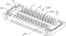
图1是本发明电连接器的立体组合图。FIG. 1 is a three-dimensional assembled view of the electrical connector of the present invention.
图2是本发明电连接器的立体分解图。Fig. 2 is an exploded perspective view of the electrical connector of the present invention.
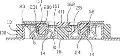
图3是沿图1中A-A线的剖切示意图,并同时展示了与本发明电连接器相对应的对接连接器的剖切示意图。Fig. 3 is a schematic cross-sectional view along line A-A in Fig. 1, and also shows a schematic cross-sectional view of a mating connector corresponding to the electrical connector of the present invention.
图4是图3所示本发明电连接器与其对接连接器的组合图。FIG. 4 is a combination diagram of the electrical connector of the present invention shown in FIG. 3 and its mating connector.
【具体实施方式】【Detailed ways】
请参阅图1所示,本发明电连接器100包括有纵长的绝缘本体1、沿纵长方向排列并固持于绝缘本体上的数个端子2及安装于绝缘本体的纵长两端的固持件3。Please refer to FIG. 1, the
请参阅图2所示,所述绝缘本体1具有对接面11及自该对接面11凹设的对接空间12,该绝缘本体包括有两侧壁13、垂直连接两侧壁的底壁14、端壁15及自底壁14凸伸设置于两侧壁之间的舌板16,该侧壁、底壁及端壁形成上述对接空间12,且绝缘本体1形成有收容槽121,端子2收容于该收容槽内。2, the insulating body 1 has a
请参阅图2及图3所示,所述端子2依次设置有固持于侧壁13上的固持部21及自固持部沿收容槽延伸的弹性臂,该弹性臂包括有:自固持部21一端向对接空间一侧弯折延伸的延伸部22、自延伸部22靠近对接空间的一端弯折延伸入底壁14的第一接触臂部23、自第一接触臂部23位于底侧的一端向舌板16弯折延伸的连接臂部24、自连接臂部24靠近舌板的一端向对接面11弯折延伸的第二接触臂部25,前述第一接触臂部23及第二接触臂部25沿垂直于纵长方向的横向方向上相对分隔设置于收容槽121的两侧,从而可与对接连接器的两相对接触部电性接触,可提高接触的可靠性。Please refer to FIG. 2 and FIG. 3 , the
请参阅图3及图4所示,与本发明电连接器相配合的对接连接器200具有绝缘本体4及固持于绝缘本体的数个端子5,所述绝缘本体具有底壁41及垂直于底壁围绕设置的侧壁42;端子5固持于两纵长侧壁上,且具有分别与电连接器100的第一、第二接触臂部相接触的第一接触部51及第二接触部52,该第一、第二接触部相对设置于侧壁42的外侧及内侧,其中第一接触部51与绝缘本体4之间具有间隙,且该第一接触部51的末端外侧形成有凹部511,第二接触部52自第一接触部向绝缘本体内弯折延伸,且形成逐渐向内侧倾斜的导引面521,即两侧壁42上相对的第二接触部52形成开口大而底部小的梯形空腔,以方便电连接器100的舌板16可收容于上述梯形空腔内,电连接器100的第一接触臂部23具有与对接连接器200的凹部511相卡合的触点231,有利于提高两连接器的接触效果,且上述倾斜的导引面可导引对接连接器200插入,可减小对接连接器所需的插入力。3 and 4, the
本发明电连接器100的端子2具有如下构造,请参阅图3及图4所示,该端子2的第一接触臂部23与连接臂部24之间的弯折角度a位于30度至60度之间,在该角度范围内,对接连接器插入过程中,对接连接器200的第一接触部51作用于电连接器100第一接触臂部23上的合成力矩偏向侧壁13一侧,可防止第一接触臂部23被压垮而变形;所述第二接触臂部25与连接臂部24之间的弯折角度b位于10度至40度之间,在该角度范围内,对接连接器200的第二接触部52作用于第二接触臂部25上的合成力矩偏向舌板16一侧,可防止第二接触臂部25向底壁14一侧过度变形而无法恢复原有弹性。The
请参阅图1、图3及图4所示,所述收容槽121内设有挡止部161,该挡止部是位于第二接触臂部25与连接臂部24相连接处的上侧,本实施方式中,挡止部161形成于舌板的两侧,可挡止第二接触臂部25被对接连接器的端子带出而影响再次对接的对接效果;第二接触臂部25的自由末端251朝挡止部161一侧弯折而呈“S”形,可防止该第二接触臂部25被压垮而变形,所述第二接触臂部25与连接臂部24之间的弯折角度b位于10度至40度之间,该弯折角度可使本发明电连接器在满足低构型需求的同时,并可改善挡止部161的厚度,提高舌板16的强度,从而防止端子2的第二接触臂部25挤压破坏挡止部161。电连接器100的舌板16的顶面凹设有槽道162,对接连接器200的底壁41具有与该凹槽相配合的凸部411,有利于提高两连接器的配合强度。Please refer to FIG. 1 , FIG. 3 and FIG. 4 , the
请参阅图1及图2所示,本发明电连接器100的固持件3包括有主体部31、自该主体部向绝缘本体外侧延伸的安装部32及自主体部向上弯折延伸的导引部33,绝缘本体的端壁15设有与该导引部相配合的凹部151,该导引部可导引对接连接器顺利插入,且可防止刮擦对接连接器的绝缘本体。1 and 2, the
上述实施方式为本发明电连接器的较佳实施方式,当然本发明电连接器也可采用其它实施方式,此处不再一一赘述。The above-mentioned implementation modes are the preferred implementation modes of the electrical connector of the present invention, of course, the electrical connector of the present invention can also adopt other implementation modes, which will not be repeated here.
Claims (10)
Translated fromChinesePriority Applications (1)
| Application Number | Priority Date | Filing Date | Title |
|---|---|---|---|
| CN2008101967030ACN101677154B (en) | 2008-09-17 | 2008-09-17 | Electric connector |
Applications Claiming Priority (1)
| Application Number | Priority Date | Filing Date | Title |
|---|---|---|---|
| CN2008101967030ACN101677154B (en) | 2008-09-17 | 2008-09-17 | Electric connector |
Publications (2)
| Publication Number | Publication Date |
|---|---|
| CN101677154A CN101677154A (en) | 2010-03-24 |
| CN101677154Btrue CN101677154B (en) | 2012-05-23 |
Family
ID=42029622
Family Applications (1)
| Application Number | Title | Priority Date | Filing Date |
|---|---|---|---|
| CN2008101967030AExpired - Fee RelatedCN101677154B (en) | 2008-09-17 | 2008-09-17 | Electric connector |
Country Status (1)
| Country | Link |
|---|---|
| CN (1) | CN101677154B (en) |
Families Citing this family (3)
| Publication number | Priority date | Publication date | Assignee | Title |
|---|---|---|---|---|
| JP6857073B2 (en) | 2017-04-07 | 2021-04-14 | モレックス エルエルシー | Connector and connector assembly |
| CN111736077A (en)* | 2019-03-25 | 2020-10-02 | 致茂电子(苏州)有限公司 | Clip-on test set |
| CN112147374B (en)* | 2019-06-26 | 2023-03-10 | 致茂电子(苏州)有限公司 | Clamp type testing device and conductive module |
Citations (5)
| Publication number | Priority date | Publication date | Assignee | Title |
|---|---|---|---|---|
| JP2004055463A (en)* | 2002-07-23 | 2004-02-19 | Matsushita Electric Works Ltd | Connector |
| CN2643494Y (en)* | 2003-07-03 | 2004-09-22 | 鸿松精密科技股份有限公司 | Board-to-Board Plug Connectors |
| CN2746581Y (en)* | 2004-09-24 | 2005-12-14 | 安诺电子股份有限公司 | Combined structure of board-to-board connectors |
| US6986670B2 (en)* | 2002-07-23 | 2006-01-17 | Matsushita Electric Works, Ltd. | Low-profile connector |
| CN201060980Y (en)* | 2007-03-22 | 2008-05-14 | 李金雅 | Connector structure |
- 2008
- 2008-09-17CNCN2008101967030Apatent/CN101677154B/ennot_activeExpired - Fee Related
Patent Citations (5)
| Publication number | Priority date | Publication date | Assignee | Title |
|---|---|---|---|---|
| JP2004055463A (en)* | 2002-07-23 | 2004-02-19 | Matsushita Electric Works Ltd | Connector |
| US6986670B2 (en)* | 2002-07-23 | 2006-01-17 | Matsushita Electric Works, Ltd. | Low-profile connector |
| CN2643494Y (en)* | 2003-07-03 | 2004-09-22 | 鸿松精密科技股份有限公司 | Board-to-Board Plug Connectors |
| CN2746581Y (en)* | 2004-09-24 | 2005-12-14 | 安诺电子股份有限公司 | Combined structure of board-to-board connectors |
| CN201060980Y (en)* | 2007-03-22 | 2008-05-14 | 李金雅 | Connector structure |
Also Published As
| Publication number | Publication date |
|---|---|
| CN101677154A (en) | 2010-03-24 |
Similar Documents
| Publication | Publication Date | Title |
|---|---|---|
| TWI394327B (en) | Electrical connector | |
| CN201204309Y (en) | electrical connector | |
| CN201112668Y (en) | Board-to-Board Connector | |
| CN201436718U (en) | electrical connector | |
| CN201773975U (en) | electronic card connector | |
| CN204376051U (en) | Electronic card coupler | |
| CN201336452Y (en) | Electric connector | |
| CN201515054U (en) | Board terminal electric connector | |
| CN201112941Y (en) | electrical connector | |
| CN101677154B (en) | Electric connector | |
| CN100429832C (en) | Electrical Connector Assembly | |
| US6186833B1 (en) | Hybrid connector with audio jack | |
| CN204243358U (en) | Plug connector and socket connector mated with it | |
| CN201075432Y (en) | Electric Connector | |
| CN201160138Y (en) | Electrical Connector Assembly | |
| CN201549668U (en) | Terminal and electrical connector using the terminal | |
| CN204497437U (en) | Electronic card coupler | |
| CN201285939Y (en) | Electric connector | |
| CN201029113Y (en) | electrical connector | |
| CN201440507U (en) | Electric connector | |
| CN206976628U (en) | Electronic card coupler | |
| CN201160135Y (en) | Electrical Connector Assembly | |
| CN2682602Y (en) | Electrical Connector Assembly | |
| CN204834946U (en) | Edge blocking type connector | |
| CN201966367U (en) | Electric connector and assembly thereof |
Legal Events
| Date | Code | Title | Description |
|---|---|---|---|
| C06 | Publication | ||
| PB01 | Publication | ||
| C10 | Entry into substantive examination | ||
| SE01 | Entry into force of request for substantive examination | ||
| C14 | Grant of patent or utility model | ||
| GR01 | Patent grant | ||
| CF01 | Termination of patent right due to non-payment of annual fee | ||
| CF01 | Termination of patent right due to non-payment of annual fee | Granted publication date:20120523 Termination date:20180917 |