CN101676825A - Electronic system and power supply device thereof - Google Patents
Electronic system and power supply device thereofDownload PDFInfo
- Publication number
- CN101676825A CN101676825ACN200810149179ACN200810149179ACN101676825ACN 101676825 ACN101676825 ACN 101676825ACN 200810149179 ACN200810149179 ACN 200810149179ACN 200810149179 ACN200810149179 ACN 200810149179ACN 101676825 ACN101676825 ACN 101676825A
- Authority
- CN
- China
- Prior art keywords
- electronic device
- power supply
- circuit
- voltage
- signal
- Prior art date
- Legal status (The legal status is an assumption and is not a legal conclusion. Google has not performed a legal analysis and makes no representation as to the accuracy of the status listed.)
- Pending
Links
- 238000006243chemical reactionMethods0.000claimsdescription41
- 230000001960triggered effectEffects0.000claimsdescription2
- 230000004913activationEffects0.000claims3
- 238000010586diagramMethods0.000description6
- 230000000630rising effectEffects0.000description3
- 238000000034methodMethods0.000description2
- 230000005611electricityEffects0.000description1
- 230000007613environmental effectEffects0.000description1
- 230000004048modificationEffects0.000description1
- 238000012986modificationMethods0.000description1
Images

Landscapes
- Power Sources (AREA)
Abstract
Description
Translated fromChinese技术领域technical field
本发明涉及一种电子系统及其电源供应装置,特别涉及一种可随着电子系统开机或关机而同时启动或关闭电源供应装置的供电功能的电子系统及其电源供应装置。The present invention relates to an electronic system and its power supply device, in particular to an electronic system and its power supply device which can simultaneously activate or deactivate the power supply function of the power supply device when the electronic system is turned on or off.
背景技术Background technique
目前,由于人们对环保意识的增加,越来越多用户希望电子系统能够减少耗电。大部分电子装置使用交流转直流的电源供应器来供电,然而,现有的电子装置关机或待机时,电源供应器仍然持续在供电,造成不必要的电力消耗。虽然用户可自行拔起电源供应器,但是对用户而言非常不方便。Currently, due to the increasing awareness of environmental protection, more and more users expect electronic systems to reduce power consumption. Most electronic devices are powered by an AC-to-DC power supply. However, when the existing electronic devices are turned off or in standby, the power supply continues to supply power, resulting in unnecessary power consumption. Although the user can unplug the power supply by himself, it is very inconvenient for the user.
发明内容Contents of the invention
本发明是为了解决上述问题而提出的,本发明的目的在于提供一种电子系统及其电源供应装置,以降低电源供应器在电子装置关机时的耗电。The present invention is proposed to solve the above problems. The purpose of the present invention is to provide an electronic system and a power supply device thereof, so as to reduce the power consumption of the power supply when the electronic device is turned off.
为了达到本发明的目的,本发明提供一种电源供应装置,用以对电子装置供电,所述电源供应装置包含交流/直流转换电路、电压转换电路及启动电路。交流/直流转换电路用于接收交流电压,并将所述交流电压转换成直流电压。电压转换电路用于接收所述直流电压并产生输出电压供应给电子装置。启动电路电性连接于交流/直流转换电路及电压转换电路之间,当启动电路接收电子装置所产生的开启信号时,启动电路变成导通状态,使得电压转换电路可接收直流电压,当启动电路接收电子装置所产生的关闭信号时,启动电路变成断路状态,使得电压转换电路无法接收所述直流电压。In order to achieve the objective of the present invention, the present invention provides a power supply device for supplying power to electronic devices, the power supply device includes an AC/DC conversion circuit, a voltage conversion circuit and a start-up circuit. The AC/DC conversion circuit is used for receiving the AC voltage and converting the AC voltage into a DC voltage. The voltage converting circuit is used for receiving the DC voltage and generating an output voltage for supplying to the electronic device. The start-up circuit is electrically connected between the AC/DC conversion circuit and the voltage conversion circuit. When the start-up circuit receives the turn-on signal generated by the electronic device, the start-up circuit becomes conductive so that the voltage conversion circuit can receive DC voltage. When the start-up circuit When the circuit receives the closing signal generated by the electronic device, the start-up circuit becomes disconnected, so that the voltage converting circuit cannot receive the DC voltage.
其中,所述电源供应装置还包含电源电缆(cable),其具有连接头以电性连接电子装置,而开启信号或关闭信号通过所述电源电缆由电子装置传送至启动电路。Wherein, the power supply device further includes a power cable (cable), which has a connector to electrically connect the electronic device, and a turn-on signal or a turn-off signal is transmitted from the electronic device to the startup circuit through the power cable.
其中,所述连接头具有至少三个引脚(pin)。Wherein, the connector has at least three pins.
其中,所述电源供应装置还包含电源排线,其电性连接电子装置,开启信号或关闭信号通过电源排线传送至启动电路。Wherein, the power supply device further includes a power cable, which is electrically connected to the electronic device, and the on signal or the off signal is transmitted to the startup circuit through the power cable.
为了达到本发明的目的,本发明提供一种电子系统,包含电子装置及电源供应装置。电源供应装置包含交流/直流转换电路、电压转换电路及启动电路。而交流/直流转换电路用于接收交流电压,并将所述交流电压转换成直流电压,而电压转换电路用于接收直流电压并产生输出电压供应给电子装置,而启动电路电性连接于交流/直流转换电路及电压转换电路之间。当电子装置开机时,电子装置传送开启信号至启动电路,致使启动电路变成导通状态,使得电压转换电路能够接收直流电压。当电子装置关机时,电子装置传送关闭信号至启动电路,致使启动电路变成断路状态,使得电压转换电路无法接收直流电压。In order to achieve the object of the present invention, the present invention provides an electronic system including an electronic device and a power supply device. The power supply device includes an AC/DC conversion circuit, a voltage conversion circuit and a starting circuit. The AC/DC conversion circuit is used to receive the AC voltage and convert the AC voltage into a DC voltage, and the voltage conversion circuit is used to receive the DC voltage and generate an output voltage to supply to the electronic device, and the starting circuit is electrically connected to the AC/DC. Between the DC conversion circuit and the voltage conversion circuit. When the electronic device is turned on, the electronic device transmits a turn-on signal to the start-up circuit, causing the start-up circuit to be turned on, so that the voltage conversion circuit can receive the DC voltage. When the electronic device is turned off, the electronic device sends a shutdown signal to the startup circuit, causing the startup circuit to be in an open circuit state, so that the voltage conversion circuit cannot receive the DC voltage.
其中,开启信号或关闭信号由所述电子装置的开关所产生。Wherein, the on signal or the off signal is generated by a switch of the electronic device.
其中,电子装置的开关被触发,以使电子装置开机或关机时,开启信号或关闭信号由电子装置的嵌入式控制器所产生。Wherein, the switch of the electronic device is triggered, so that when the electronic device is turned on or off, the on signal or the off signal is generated by the embedded controller of the electronic device.
其中,电子装置具有屏幕,且电子装置执行操作系统,并在屏幕上显示操作界面,当用户通过操作界面关机时,关闭信号由电子装置的嵌入式控制器所产生。Wherein, the electronic device has a screen, and the electronic device executes an operating system and displays an operation interface on the screen. When the user shuts down the device through the operation interface, the shutdown signal is generated by the embedded controller of the electronic device.
附图说明Description of drawings
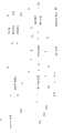
图1为本发明的电源供应装置的实施例的示意图;1 is a schematic diagram of an embodiment of a power supply device of the present invention;
图2为本发明的电子系统的第一实施例的示意图;以及2 is a schematic diagram of a first embodiment of the electronic system of the present invention; and
图3为本发明的电子系统的第二实施例的示意图。FIG. 3 is a schematic diagram of a second embodiment of the electronic system of the present invention.
主要符号说明:1、21、39为电源供应装置;11为交流/直流转换电路;12为启动电路;121、122为晶体管;13为电压转换电路;14为交流电压;15为直流电压;16为输出电压;17为控制信号;171为开启信号;172为关闭信号;19为电子装置;20、30为便携式计算机;201为开关;211为电源电缆;212为连接头;31为中央处理器;32为显示器;33为储存模块;331为操作系统;332为操作界面;333为关机图示;34为嵌入式控制器;35为开关;36为电池;37为输入装置;38为电源管理模块;391为连接头;以及392~394为引脚。Description of main symbols: 1, 21, 39 are power supply devices; 11 is AC/DC conversion circuit; 12 is starting circuit; 121, 122 are transistors; 13 is voltage conversion circuit; 14 is AC voltage; 15 is DC voltage; 16 17 is a control signal; 171 is an opening signal; 172 is a closing signal; 19 is an electronic device; 20 and 30 are portable computers; 201 is a switch; 211 is a power cable; 212 is a connector; 31 is a
具体实施方式Detailed ways
参照图1,其为本发明的电源供应装置的实施例的示意图。图中,电源供应装置1包含交流/直流转换电路11、启动电路12及电压转换电路13。交流/直流转换电路11用于接收交流电压14,并将所述交流电压14转换成直流电压15。电压转换电路13用于接收所述直流电压15并产生输出电压16供应给电子装置19作为工作电源。启动电路12电性连接于交流/直流转换电路11及电压转换电路13之间。在本实施例中,为了方便说明启动电路12的开关功能,仅对以晶体管121、122以及复数个电阻所组成的电路进行说明,但并不限于此,启动电路12也可以包含其它相关电路。电源供应装置1还可包含电源电缆(cable)或电源排线来耦接(couple)电子装置,其中,电源电缆可具有连接头以电性连接电子装置,而优选的是连接头具有至少三个引脚(pin),而电子装置19可通过电源电缆或电源排线传送控制信号17至启动电路12。Referring to FIG. 1 , it is a schematic diagram of an embodiment of the power supply device of the present invention. In the figure, the power supply device 1 includes an AC/DC conversion circuit 11 , a startup circuit 12 and a voltage conversion circuit 13 . The AC/DC conversion circuit 11 is used for receiving an AC voltage 14 and converting the AC voltage 14 into a DC voltage 15 . The voltage conversion circuit 13 is used to receive the DC voltage 15 and generate an output voltage 16 to supply the electronic device 19 as a working power. The startup circuit 12 is electrically connected between the AC/DC conversion circuit 11 and the voltage conversion circuit 13 . In this embodiment, for the convenience of illustrating the switching function of the start-up circuit 12 , only the circuit composed of transistors 121 , 122 and a plurality of resistors is described, but it is not limited thereto, and the start-up circuit 12 may also include other related circuits. The power supply device 1 can also include a power cable (cable) or a power cable to couple the electronic device, wherein the power cable can have a connector to electrically connect the electronic device, and preferably the connector has at least three The electronic device 19 can transmit the control signal 17 to the starting circuit 12 through a power cable or a power strip.
当启动电路12接收电子装置19所产生的开启信号171时,即控制信号17中由低电位转为高电位的上升沿信号,致使晶体管121及晶体管122变成导通状态(即启动电路12变成导通状态),使得电压转换电路13可接收直流电压15,进而使电子装置19可接收到输出电压16以进行运作。When the start-up circuit 12 receives the turn-on signal 171 generated by the electronic device 19, that is, the rising edge signal of the control signal 17 from a low potential to a high potential, the transistor 121 and the transistor 122 become conductive (that is, the start-up circuit 12 becomes into a conduction state), so that the voltage conversion circuit 13 can receive the DC voltage 15, and then the electronic device 19 can receive the output voltage 16 to operate.
当启动电路12接收电子装置19所产生的关闭信号172时,即控制信号17中由高电位转为低电位的下降沿信号,致使晶体管121及晶体管122变成于关闭状态(即启动电路12变成断路状态),使得电压转换电路13无法接收所述直流电压15。When the startup circuit 12 receives the closing signal 172 generated by the electronic device 19, that is, the falling edge signal of the control signal 17 from a high potential to a low potential, the transistor 121 and the transistor 122 become in the off state (that is, the startup circuit 12 becomes into an open circuit state), so that the voltage converting circuit 13 cannot receive the DC voltage 15 .
由此,当电子装置19关机时,可通过传送关闭信号172来使启动电路12断路,让电压转换电路13无法接收直流电压15,电源供应装置1不再输出电力,与现有技术相比,本发明的电源供应装置1在不供电的情况下可避免电压转换电路持续的耗电。当电子装置19开机时,可通过传送开启信号171来开启启动电路12,电源供应装置1便可供电给电子装置19。Thus, when the electronic device 19 is turned off, the start-up circuit 12 can be disconnected by sending the shutdown signal 172, so that the voltage conversion circuit 13 cannot receive the DC voltage 15, and the power supply device 1 no longer outputs power. Compared with the prior art, The power supply device 1 of the present invention can avoid continuous power consumption of the voltage conversion circuit in the case of no power supply. When the electronic device 19 is turned on, the start-up circuit 12 can be turned on by transmitting the start signal 171 , and the power supply device 1 can supply power to the electronic device 19 .
电子装置19为台式计算机、便携式计算机或电视机,或是任何外接或内建交流转直流的电源供应装置的电器产品。而电压转换电路13可包含PWM控制器、变压器及整流电路,变压器的一次侧接收直流电压15,而变压器的二次侧输出感应电流,整流电路连接变压器的二次侧输出端,用以转换产生输出电压16,而PWM控制器输出位准信号至变压器,启动电路12电性连接PWM控制器。The electronic device 19 is a desktop computer, a portable computer or a television, or any electrical product with an external or built-in AC-to-DC power supply device. The voltage conversion circuit 13 may include a PWM controller, a transformer, and a rectifier circuit. The primary side of the transformer receives the DC voltage 15, and the secondary side of the transformer outputs an induced current. The output voltage is 16, and the PWM controller outputs a level signal to the transformer, and the starting circuit 12 is electrically connected to the PWM controller.
值得注意的是,图1所示的实施例以晶体管来实现启动电路的开关功能,以及分别以上升沿信号及下降沿信号作为开启信号及关闭信号,但本发明并不限于此。It should be noted that in the embodiment shown in FIG. 1 , transistors are used to implement the switching function of the start-up circuit, and rising edge signals and falling edge signals are used as the turn-on and turn-off signals respectively, but the present invention is not limited thereto.
参照图2,其为本发明的电子系统的第一实施例的示意图。图中,以便携式计算机20作为电子装置的实施例,便携式计算机20连接电源供应装置21的电源电缆211的连接头212,而连接头212具有三个引脚(未图示),其中第一引脚及第二引脚用以传送正负电压,而第三引脚可用以传送启动信号或关闭信号。当用户按压便携式计算机20的开关201来开机时,按压开关201的动作可使连接头212的第三引脚上的电位信号由低电位变为高电位,并持续维持在高电位,例如,开关201被按压时将便携式计算机20的电池与连接头212的第三引脚导通,而开关201可包含锁相器(latch)来维持第三引脚上的电位信号处于高电位。如结合图1说明的动作原理,电源供应装置21中的启动电路接收到低电位转为高电位的上升沿信号后,可使电源供应装置21开始供电,此时便携式计算机20可利用电源供应装置21所供应的电力来运行并对电池充电。Referring to FIG. 2 , it is a schematic diagram of the first embodiment of the electronic system of the present invention. In the figure, the
同理,当用户再次按压便携式计算机20的开关201来关机时,使连接头212的第三引脚上的电位信号由高电位变为低电位,致使电源供应装置21停止供电。Similarly, when the user presses the
参照图3,其为本发明的电子系统的第二实施例的框图。图中,以便携式计算机30作为电子装置的实施例,便携式计算机30包含中央处理器31、显示器32、储存模块33、嵌入式控制器(EC)34、开关35、电池36、输入装置37及电源管理模块38。储存模块33至少储存有一个操作系统331。当用户按压开关35后,致使电池36供电给嵌入式控制器34,嵌入式控制器34启动后接着启动执行供电程序,以供电给便携式计算机30内的电子组件,例如中央处理器31、显示器32及储存模块33。而所述供电程序是本领域的技术人员所熟知的内容,因此不再详述。接着,中央处理器31自储存模块33读取操作系统331并执行,并驱动显示器32显示操作系统331的操作界面332,用户可使用输入装置37来控制操作界面332。Referring to FIG. 3 , it is a block diagram of a second embodiment of the electronic system of the present invention. In the figure, a portable computer 30 is used as an embodiment of an electronic device. The portable computer 30 includes a
操作界面332上具有关机图示333,当用户使用输入装置37触发关机图标333来关闭便携式计算机30时,中央处理器31执行关机程序,最后输出通知信号至嵌入式控制器34以停止电源管理模块38供电给电子组件,进而关闭便携式计算机30。因此,在第二实施例中,电源供应装置39的连接头391的第一引脚392及第二引脚393可电性连接电源管理模块38,而第三引脚394可电性连接嵌入式控制器34,如此无论用户通过按压开关来开机或关机、或是通过触发关机图示333来关机,嵌入式控制器34都可以使第三引脚394产生相对应的开启信号或关闭信号。There is a
值得注意的是,上述实施例以计算机作为实施例进行了说明,但并不限于此,例如电视机也可以触发电视机上的开关或是遥控器上的按键两种方式来开启或关闭电视机,也可依照上述的动作原理使得电视机开启或关闭,此时,其电源供应装置也会根据电视机的开启或关闭开始供电或停止供电,这种方式同样包含于本发明的保护范围内。电子装置可为台式计算机、便携式计算机或电视机,或是任何外接或内建交流转直流的电源供应装置的电器产品。It is worth noting that the above-mentioned embodiments have been described with a computer as an embodiment, but it is not limited thereto. For example, the TV can also trigger the switch on the TV or the button on the remote control to turn on or off the TV. The TV set can also be turned on or off according to the above-mentioned action principle. At this time, its power supply device will also start or stop supplying power according to the turn on or off of the TV set. This method is also included in the protection scope of the present invention. The electronic device can be a desktop computer, a portable computer or a television, or any electrical product with an external or built-in AC-to-DC power supply device.
通过上述说明可知,本发明的电子系统可使用户在关闭电子装置时,无需手动地将电源供应装置从插座拔出,电源供应装置可接收关闭信号并根据所述关闭信号而停止运行电压转换电路,由此降低电源供应装置在不供电状态下的耗电。From the above description, it can be seen that the electronic system of the present invention enables the user to turn off the electronic device without manually pulling out the power supply device from the socket, and the power supply device can receive the shutdown signal and stop the operation of the voltage conversion circuit according to the shutdown signal , thereby reducing the power consumption of the power supply device in a state of no power supply.
以上所述仅为举例性的,而不是限制性的。任何未脱离本发明的精神与范畴,而对其进行的等效修改或变更,均应包含于本发明的权利要求范围之内。The above descriptions are illustrative only, not limiting. Any equivalent modification or change without departing from the spirit and scope of the present invention shall be included in the scope of the claims of the present invention.
Claims (13)
Translated fromChinesePriority Applications (1)
| Application Number | Priority Date | Filing Date | Title |
|---|---|---|---|
| CN200810149179ACN101676825A (en) | 2008-09-19 | 2008-09-19 | Electronic system and power supply device thereof |
Applications Claiming Priority (1)
| Application Number | Priority Date | Filing Date | Title |
|---|---|---|---|
| CN200810149179ACN101676825A (en) | 2008-09-19 | 2008-09-19 | Electronic system and power supply device thereof |
Publications (1)
| Publication Number | Publication Date |
|---|---|
| CN101676825Atrue CN101676825A (en) | 2010-03-24 |
Family
ID=42029417
Family Applications (1)
| Application Number | Title | Priority Date | Filing Date |
|---|---|---|---|
| CN200810149179APendingCN101676825A (en) | 2008-09-19 | 2008-09-19 | Electronic system and power supply device thereof |
Country Status (1)
| Country | Link |
|---|---|
| CN (1) | CN101676825A (en) |
Cited By (3)
| Publication number | Priority date | Publication date | Assignee | Title |
|---|---|---|---|---|
| CN102681448A (en)* | 2011-03-17 | 2012-09-19 | 和硕联合科技股份有限公司 | Electronic device |
| WO2016065783A1 (en)* | 2014-10-31 | 2016-05-06 | 京东方科技集团股份有限公司 | Television set and desktop display device |
| CN106095036A (en)* | 2015-04-30 | 2016-11-09 | 群晖科技股份有限公司 | Method and apparatus for power management in an electronic system |
- 2008
- 2008-09-19CNCN200810149179Apatent/CN101676825A/enactivePending
Cited By (7)
| Publication number | Priority date | Publication date | Assignee | Title |
|---|---|---|---|---|
| CN102681448A (en)* | 2011-03-17 | 2012-09-19 | 和硕联合科技股份有限公司 | Electronic device |
| CN102681448B (en)* | 2011-03-17 | 2015-05-13 | 和硕联合科技股份有限公司 | Electronic device |
| WO2016065783A1 (en)* | 2014-10-31 | 2016-05-06 | 京东方科技集团股份有限公司 | Television set and desktop display device |
| US10044971B2 (en) | 2014-10-31 | 2018-08-07 | Boe Technology Group Co., Ltd. | Television set and desktop display apparatus |
| CN106095036A (en)* | 2015-04-30 | 2016-11-09 | 群晖科技股份有限公司 | Method and apparatus for power management in an electronic system |
| US10162398B2 (en) | 2015-04-30 | 2018-12-25 | Synology Incorporated | Method and associated apparatus for performing power management in an electronic system |
| CN106095036B (en)* | 2015-04-30 | 2019-04-05 | 群晖科技股份有限公司 | Method and apparatus for power management in an electronic system |
Similar Documents
| Publication | Publication Date | Title |
|---|---|---|
| CN101576767B (en) | Main board power supply circuit | |
| TW200921359A (en) | Electronic device, computer, arrangement, and method for controlling an electronic device | |
| US9244509B2 (en) | Uninterruptible power system and power control system thereof | |
| CN102866769B (en) | Display terminal | |
| CN102882364A (en) | Energy-saving switch device and method | |
| CN114035702B (en) | Touch wakeup method and device of display equipment, power supply circuit and display equipment | |
| CN102880280A (en) | Display terminal | |
| US8897044B2 (en) | Electronic device having complete power-saving mechanism | |
| CN101465600A (en) | Electronic equipment and power supply device thereof | |
| CN101727173B (en) | Economizer | |
| CN106712155A (en) | Power saving device for embedded power supply | |
| CN101676825A (en) | Electronic system and power supply device thereof | |
| CN111399617B (en) | Power supply control device and electronic apparatus | |
| TWI463797B (en) | Power switching circuit | |
| TWI533115B (en) | Electronic device and power management control method | |
| EP2720356B1 (en) | Power supply system and power control circuit thereof | |
| CN213043666U (en) | Low-power consumption standby electronic equipment | |
| TW201321955A (en) | Power control device and electronic device using the same | |
| CN113625856A (en) | Switching on and shutting down circuit and electronic equipment | |
| CN210924256U (en) | Battery starting circuit | |
| CN219801915U (en) | Power supply control device, power supply assembly and electronic device | |
| US20100067265A1 (en) | Electronic system and power supply device thereof | |
| CN110928392A (en) | Power supply control device and electronic apparatus | |
| CN102799249B (en) | A kind of computing machine and power control thereof | |
| CN201508523U (en) | System device for remotely controlling main controlled equipment and power distribution facility |
Legal Events
| Date | Code | Title | Description |
|---|---|---|---|
| C06 | Publication | ||
| PB01 | Publication | ||
| C10 | Entry into substantive examination | ||
| SE01 | Entry into force of request for substantive examination | ||
| C02 | Deemed withdrawal of patent application after publication (patent law 2001) | ||
| WD01 | Invention patent application deemed withdrawn after publication | Open date:20100324 |