CN101675584B - Amplifier pre-distortion systems and methods - Google Patents
Amplifier pre-distortion systems and methodsDownload PDFInfo
- Publication number
- CN101675584B CN101675584BCN2008800148891ACN200880014889ACN101675584BCN 101675584 BCN101675584 BCN 101675584BCN 2008800148891 ACN2008800148891 ACN 2008800148891ACN 200880014889 ACN200880014889 ACN 200880014889ACN 101675584 BCN101675584 BCN 101675584B
- Authority
- CN
- China
- Prior art keywords
- branch
- amplifier
- signal
- subsignal
- digital
- Prior art date
- Legal status (The legal status is an assumption and is not a legal conclusion. Google has not performed a legal analysis and makes no representation as to the accuracy of the status listed.)
- Expired - Fee Related
Links
Images


Classifications
- H—ELECTRICITY
- H04—ELECTRIC COMMUNICATION TECHNIQUE
- H04L—TRANSMISSION OF DIGITAL INFORMATION, e.g. TELEGRAPHIC COMMUNICATION
- H04L27/00—Modulated-carrier systems
- H04L27/32—Carrier systems characterised by combinations of two or more of the types covered by groups H04L27/02, H04L27/10, H04L27/18 or H04L27/26
- H04L27/34—Amplitude- and phase-modulated carrier systems, e.g. quadrature-amplitude modulated carrier systems
- H04L27/36—Modulator circuits; Transmitter circuits
- H04L27/366—Arrangements for compensating undesirable properties of the transmission path between the modulator and the demodulator
- H—ELECTRICITY
- H03—ELECTRONIC CIRCUITRY
- H03F—AMPLIFIERS
- H03F1/00—Details of amplifiers with only discharge tubes, only semiconductor devices or only unspecified devices as amplifying elements
- H03F1/02—Modifications of amplifiers to raise the efficiency, e.g. gliding Class A stages, use of an auxiliary oscillation
- H03F1/0205—Modifications of amplifiers to raise the efficiency, e.g. gliding Class A stages, use of an auxiliary oscillation in transistor amplifiers
- H03F1/0288—Modifications of amplifiers to raise the efficiency, e.g. gliding Class A stages, use of an auxiliary oscillation in transistor amplifiers using a main and one or several auxiliary peaking amplifiers whereby the load is connected to the main amplifier using an impedance inverter, e.g. Doherty amplifiers
- H—ELECTRICITY
- H03—ELECTRONIC CIRCUITRY
- H03F—AMPLIFIERS
- H03F1/00—Details of amplifiers with only discharge tubes, only semiconductor devices or only unspecified devices as amplifying elements
- H03F1/32—Modifications of amplifiers to reduce non-linear distortion
- H03F1/3241—Modifications of amplifiers to reduce non-linear distortion using predistortion circuits
- H03F1/3247—Modifications of amplifiers to reduce non-linear distortion using predistortion circuits using feedback acting on predistortion circuits
- H—ELECTRICITY
- H03—ELECTRONIC CIRCUITRY
- H03F—AMPLIFIERS
- H03F2200/00—Indexing scheme relating to amplifiers
- H03F2200/321—Use of a microprocessor in an amplifier circuit or its control circuit
Landscapes
- Engineering & Computer Science (AREA)
- Power Engineering (AREA)
- Computer Networks & Wireless Communication (AREA)
- Signal Processing (AREA)
- Physics & Mathematics (AREA)
- Nonlinear Science (AREA)
- Amplifiers (AREA)
Abstract
Translated fromChineseDescription
Translated fromChinese技术领域technical field
本发明涉及预失真放大器,更具体地说,涉及预失真多通道功率放大器布置。The present invention relates to predistortion amplifiers, and more particularly to predistortion multi-channel power amplifier arrangements.
背景技术Background technique
放大器的随其输入电压而变化的电压输出在输入电压,尤其是较大输入电压的某些范围内通常不是线性的。预失真是一种使输入信号预失真,以便补偿放大器的这些非线性范围的技术。The voltage output of an amplifier, which varies with its input voltage, is generally not linear over certain ranges of input voltage, especially larger input voltages. Predistortion is a technique that predistorts the input signal in order to compensate for these non-linear ranges of the amplifier.
关于无线基站的功率放大器设计的目的之一是提高效率。效率的提高能够导致放大器成本降低(例如,通过允许使用功率处理能力降低的更便宜的晶体管)和经营费用降低(例如,减小尺寸、降低冷却要求、降低功率要求等)。在常规的功率放大器中,通常对AB类输出级构造应用各种技术,以获得所需水平的性能,但是,这些技术的益处在效率方面受AB类输出级限制。One of the purposes of designing power amplifiers for wireless base stations is to improve efficiency. Improvements in efficiency can lead to reduced amplifier cost (eg, by allowing the use of cheaper transistors with reduced power handling capabilities) and reduced operating expenses (eg, reduced size, reduced cooling requirements, reduced power requirements, etc.). In conventional power amplifiers, various techniques are typically applied to the class AB output stage construction to obtain the desired level of performance, however, the benefits of these techniques are limited in efficiency by the class AB output stage.
诸如所谓的Doherty放大器之类的多通道输出级提供增大效率的潜力,不过难以使输入预失真,以满足这种放大器布置的过分要求的无线规范。借助不对称的Doherty放大器(例如,对主放大器和峰化放大器使用不同技术的Doherty放大器布置)能够获得进一步的效率提高,不过这样的布置进一步增大了预失真难题。Multi-channel output stages such as so-called Doherty amplifiers offer the potential for increased efficiency, but it is difficult to predistort the input to meet the demanding wireless specifications of such amplifier arrangements. Further efficiency gains can be obtained with asymmetrical Doherty amplifiers (eg, a Doherty amplifier arrangement using different technologies for the main and peaking amplifiers), but such an arrangement further increases the predistortion challenge.
迫切需要至少克服一些上述缺陷的优化多通道放大器的性能的技术。There is an urgent need for techniques to optimize the performance of multi-channel amplifiers that overcome at least some of the above-mentioned deficiencies.
发明内容Contents of the invention
通过提供优化多通道放大器的性能的技术,本发明解决了上述问题。The present invention addresses the above-mentioned problems by providing techniques for optimizing the performance of multi-channel amplifiers.
从而,本发明的一个方面提供一种优化Doherty放大器的性能的方法,所述方法包括:分配(Splitting)输入信号以得到Doherty放大器的每个分支的相应子信号;利用Doherty放大器的相关分支的已知性能特性,独立地预失真每个子信号;和把每个预失真的子信号提供给Doherty放大器的相关分支。Thereby, one aspect of the present invention provides a kind of method of optimizing the performance of Doherty amplifier, said method comprises: distribution (Splitting) input signal to obtain the corresponding sub-signal of each branch of Doherty amplifier; knowing performance characteristics, independently predistorting each sub-signal; and providing each pre-distorted sub-signal to an associated branch of a Doherty amplifier.
本发明的实施例采用可使用输入信号的知识(比如包络、振幅或相位,或者参数的某种组合),以及其它可用的系统波形和特性(例如,TDD状态)的预失真机制。本发明的实施例可以提供下述任意之一或者多个:(a)能够产生预失真特性的多输入预失真机制;(b)产生多个不同的预失真输出,以便支持多输入放大器布置的能力;(c)能够支持多放大器体系结构或者单一放大器的多样特性(例如,在不同的工作条件下)的可动态重新配置的预失真体系结构;(d)确定最佳预失真系数的硬件高效的训练算法和机制;和(e)使用输入包络和输入信号把预失真划分成不同的区域。这些区域可以重叠或者可以不重叠。这样,能够获得提高的多通道功率放大器布置的预失真性能。Embodiments of the present invention employ predistortion mechanisms that may use knowledge of the input signal (such as envelope, amplitude or phase, or some combination of parameters), and other available system waveforms and characteristics (eg, TDD state). Embodiments of the present invention may provide any one or more of: (a) a multiple-input predistortion mechanism capable of producing predistortion characteristics; (b) multiple different predistortion outputs to support multiple-input amplifier arrangements capabilities; (c) a dynamically reconfigurable predistortion architecture capable of supporting multi-amplifier architectures or varying characteristics of a single amplifier (e.g., under different operating conditions); (d) hardware efficient and (e) using the input envelope and the input signal to divide the predistortion into different regions. These regions may or may not overlap. In this way, improved predistortion performance of the multi-channel power amplifier arrangement can be obtained.
附图说明Description of drawings
结合附图,根据下面的详细说明,本发明的其它特征和优点将变得明显,其中:Other features and advantages of the present invention will become apparent from the following detailed description, taken in conjunction with the accompanying drawings, in which:
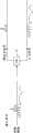
图1是示意图解说明现有技术中已知的典型Doherty放大器系统的方框图;Figure 1 is a block diagram schematically illustrating a typical Doherty amplifier system known in the prior art;
图2是示意图解说明按照本发明的第一代表性实施例的多通道放大器系统的方框图;2 is a block diagram schematically illustrating a multi-channel amplifier system according to a first representative embodiment of the present invention;
图3示意图解说明可用在图2的多通道放大器中的分配器(Splitter)的操作;Figure 3 schematically illustrates the operation of a splitter (Splitter) that can be used in the multi-channel amplifier of Figure 2;
图4是示意图解说明按照本发明的第二代表性实施例的多通道放大器系统的方框图;4 is a block diagram schematically illustrating a multi-channel amplifier system according to a second representative embodiment of the present invention;
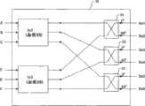
图5是示意图解说明可用在图4的系统中的三分支功率放大器的方框图;FIG. 5 is a block diagram schematically illustrating a three-branch power amplifier usable in the system of FIG. 4;
图6是示意图解说明可用在图4的系统中的备选三分支功率放大器的方框图;FIG. 6 is a block diagram schematically illustrating an alternative three-branch power amplifier that may be used in the system of FIG. 4;
图7是示意图解说明可用在图4的系统中的通用N-分支功率放大器的方框图;FIG. 7 is a block diagram schematically illustrating a general N-branch power amplifier usable in the system of FIG. 4;
图8A图解说明本领域中已知的两种90°桥接岔路(hybrid);以及Figure 8A illustrates two 90° bridge hybrids known in the art; and
图8B-C是示意图解说明利用图8A中所示的90°桥接岔路构成的可能的组合器网络的方框图。8B-C are block diagrams schematically illustrating possible combiner networks constructed using the 90° bridging branches shown in FIG. 8A.
注意在附图中,相同的特征用相同的附图标记识别。Note that in the drawings, like features are identified with like reference numerals.
具体实施方式Detailed ways
本发明提供各种构造的多通道功率放大器的预失真技术。下面参考图1-7举例说明本发明的实施例。The present invention provides predistortion technology for multi-channel power amplifiers with various structures. Embodiments of the present invention are illustrated below with reference to FIGS. 1-7 .
适用于使功率放大器(PA)预失真的一种常规技术是把PA看作单入-单出块,并根据原始信号和在PA的输出端的信号So的比较,使输入信号Si预失真。尽管这在PA中只存在“一个通道”的情况下有效,不过它并不提供对多通道功率放大器中的多个通道的任何独立校正。One conventional technique suitable for predistorting a power amplifier (PA) is to treat the PA as a single-in-single-out block, and predistort the input signal Si based on a comparison of the original signal with the signal So at the output of the PA. While this works where there is only "one channel" in the PA, it does not provide any independent correction of the channels in a multi-channel power amplifier.
参见图1,典型的Doherty放大器2包括信号分配器4、峰化放大器6、主放大器8和组合器网络10。操作中,射频(RF)输入信号Si被模拟功率分配器4分配,并被提供给两个放大器6和8。相应的放大信号随后由组合器网络10重新组合以产生输出信号So。通常,放大器输入信号Si由线性化器12生成,线性化器12通常与模拟上变频块14级联。本领域中已知,线性化器12预失真基带输入信号Sb,以便补偿上变频器14和放大器2的非线性。上变频块14把预失真的基带信号上变频到射频(RF)。Referring to FIG. 1 , a typical Doherty amplifier 2 includes a signal splitter 4 , a peaking
在一些情况下,通过利用公知的电路技术,可以实现模拟线性化。不过,更通用的布置通过利用根据从放大器输出信号So得到的反馈信号Sf计算的系数,在线性化器12中实现数字功能。线性化器12输出的预失真信号Sb′随后由数-模转换器(DAC)16转换成模拟基带信号。数字预失真的优点在于能够利用已知技术,自适应地计算系数,从而把输出信号So优化到与利用模拟线性化技术所能实现的精度相比要高得多的精度。该训练操作可根据需要进行一次(例如,在系统配置和测试期间),或者在运行时期中定期进行。本领域中已知,数字信号预失真能够补偿记忆效应,从而恰当地调整施加于放大器2的信号的振幅和相位非线性。In some cases, analog linearization can be achieved by utilizing well-known circuit techniques. However, a more general arrangement implements the digital function in the
本领域中已知,反馈信号Sf能够与Sb(或者Si)组合,以计算各种已知的误差函数或成本函数任意之一。线性化器随后能够通过操作计算系数,以便优化输出信号So的值。在一些情况下,这意味迫使输入信号Sb和经比例缩放的反馈信号Sf之间的差值达到局部极小值,而在其它情况下,迫使该差值为零(或者某一其它预定值)。在任何一种情况下,或者通过把RF输出信号So下变频到基带,随后对基带信号采样,或者通过对RF输出信号So采样,都可在数字域中实现反馈回路。前一种技术允许可能更高的精度,但是代价是接收机更复杂,而后一种技术以精度为代价实现成本较低的接收机。It is known in the art that the feedback signal Sf can be combined with Sb (or Si) to calculate any one of various known error functions or cost functions. The linearizer can then be operated to calculate coefficients in order to optimize the value of the output signal So. In some cases this means forcing the difference between the input signal Sb and the scaled feedback signal Sf to a local minimum, while in other cases forcing the difference to zero (or some other predetermined value) . In either case, the feedback loop can be implemented in the digital domain, either by downconverting the RF output signal So to baseband and subsequently sampling the baseband signal, or by sampling the RF output signal So. The former technique allows potentially higher accuracy, but at the cost of a more complex receiver, while the latter technique enables a lower cost receiver at the expense of accuracy.
如上所述,在典型的Doherty放大器2中,输入信号Si在位于线性化器12下游的放大器2内被分配。鉴于这种布置,Doherty放大器2通常被视为单入/单出块,线性化器必须被设计成通过把峰化放大器6和主放大器8看作单一放大器块,优化系统性能。这种预失真方法意味非线性的补偿取决于峰化放大器6和主放大器8之间的密切匹配。由于各种原因,比如制造变化,很难实现峰化放大器6和主放大器8之间的完美对称,从而能够获得的信号校正的程度受到限制。另外,这也限制了使用不同(不匹配)放大器(晶体管)的能力。As mentioned above, in a typical Doherty amplifier 2 the input signal Si is distributed within the amplifier 2 downstream of the
通过提供其中独立地预失真多通道放大器的每个通道的系统,本发明克服了这些问题。下面说明本发明的代表性实施例。The present invention overcomes these problems by providing a system in which each channel of a multi-channel amplifier is independently predistorted. Representative examples of the present invention are described below.
图2表示按照本发明的系统的第一代表性实施例。从图2中可看出,除了去掉了模拟分配器之外,改进的Doherty放大器18类似于图1的标准Doherty放大器2。这意味改进的Doherty放大器18是一个双入/单出设备,其中两个分支6、8都可用于独立的预失真。提供对应的数字线性化器20,数字线性化器20包括处理基带输入信号Sb以得到相应的分支子信号Sp和Sm的数字信号处理功能元件(DSP)22,分支子信号Sp和Sm随后均由相应的预失真块24处理。每个预失真块24按照和上面所述类似的方式,根据利用反馈信号Sf计算的相应系数,实现数字线性化功能。不过,在这种情况下,可以计算提供给每个预失真块24的系数,以便相互独立地优化每个峰化放大器通道和主放大器通道。在改进的Doherty放大器18的上游,可以提供相应的DAC 18(图2中未示出)和模拟上变频器14,用于把每个预失真分支子信号上变频到RF。Figure 2 shows a first representative embodiment of a system according to the present invention. As can be seen from FIG. 2, the modified Doherty
数字信号处理功能元件22可实现用于从基带输入信号Sb得到分支子信号Sp和Sm的任意各种技术。例如,DSP 22可利用预定阈值实现振幅分配方案,如下更详细所述。另外,可以实现功率分配方案,比如两个分支子信号的功率电平相等(或者遵循某一其它希望的关系)。也可使用其它数学函数来产生分支子信号,而不脱离本发明。The digital
可以认识到,通过在线性化器20把信号分配函数移动到数字域,与模拟功率分配器相比,能够实现更加复杂和可控的分配。一个好处在于能够用不同的多组线性化器系数预失真提供给峰化放大器6和主放大器8的相应子信号Si(p)和Si(m),从而允许实现更好的线性化。这便于灵活地设计和选择主放大器8和峰化放大器6,以致不再要求这两个放大器之间的对称。It will be appreciated that by moving the signal splitting function into the digital domain at the
在图2的实施例中,按照直接和图1的方式类似的方式,从输出信号So得到反馈信号Sf。不过,在图2的实施例中,反馈信号Sf被用于计算用于每个分支子信号Sp和Sm的各个不同的预失真系数。另一方面,如果需要的话,可单独地或者结合输出信号So,从每个峰化放大器和主放大器的输出得到反馈信号Sf(例如,通过抽取位于组合器10上游的每个放大器的输出)。作为另一种备选方案,可以单独地或者与用于此目的的任何其它参数结合地使用其它放大器参数(例如,放大器电压、电流、栅偏压等)。In the embodiment of FIG. 2 , the feedback signal Sf is derived from the output signal So in a manner directly analogous to that of FIG. 1 . However, in the embodiment of Fig. 2, the feedback signal Sf is used to calculate respective different predistortion coefficients for each branch sub-signal Sp and Sm. On the other hand, the feedback signal Sf can be derived from the output of each peaking and main amplifier individually or in combination with the output signal So (for example, by decimating the output of each amplifier located upstream of the combiner 10), if desired. As a further alternative, other amplifier parameters (eg, amplifier voltage, current, gate bias, etc.) may be used alone or in combination with any other parameters used for this purpose.
仅仅作为例子,图3示意地图解说明振幅分配方案,其中通过利用预定的限幅阈值,把基带输入信号Sb(只是为了便于图解说明,所述基带输入信号Sb被表示成模拟信号)分成峰化信号Sp和主信号Sm。这种分配方法遵守典型的Doherty设计,其中主放大器8放大大部分的信号,而峰化放大器6只放大高于预定阈值(所述预定阈值通常对应于主放大器8的饱和度)的信号波峰。借助图2的布置,对于每个分支能够计算各个不同的预失真系数,以便相互独立地优化每个分支的性能。这种方法降低了对主放大器和峰化放大器设计的匹配要求,同时提高了性能。另外,DSP 22的使用意味能够根据需要调整限幅阈值,以帮助整个系统性能的优化。Merely by way of example, FIG. 3 schematically illustrates an amplitude distribution scheme in which the baseband input signal Sb (shown as an analog signal for illustrative purposes only) is divided into peaked Signal Sp and main signal Sm. This distribution method follows a typical Doherty design, where the
从图3中可看出,在限幅阈值点,每个分支子信号表现出锐转变(不连续)。在一些实施例中,由预失真器24实现的预失真(或线性化)功能可修改这些转变,以使由急剧的转变产生的乱真发射(噪声)降至最小,同时保证最终的组合输出信号如实地表示由总的放大器增益缩放的输入信号。It can be seen from FIG. 3 that each branch sub-signal exhibits a sharp transition (discontinuity) at the clipping threshold point. In some embodiments, a predistortion (or linearization) function implemented by predistorter 24 modifies these transitions to minimize spurious emissions (noise) from sharp transitions while maintaining the final combined output signal faithfully represents the input signal scaled by the overall amplifier gain.
图4和5表示利用三分支放大器26的代表性发射器系统,其中组合三个放大的子信号,以产生两个输出信号。这种情况下,线性化器20的DSP 22被用来处理两个输入信号(Sb1和Sb2),以得到三个分支子信号,随后在被放大和组合成两个对应的输出信号(So1和So2)之前,所述三个分支子信号如上所述被预失真。例如,在WiMAX系统中,输入信号Sb1和Sb2可分别代表主信号和分集信号。可以理解,这种情况下,线性化器20中DSP 22的使用便利两个输入信号Sb1和Sb2与分支子信号之间的复杂数学关系的实现。例如,DSP 22可通过操作处理两个输入信号Sb1和Sb2以产生相应的主信号A和B,以及公共的峰化信号C。4 and 5 show a representative transmitter system utilizing a three-
图4中还示出了多通道数字上变频、RF DAC和滤波器(例如声表面波(SAW)滤波器),它们均按照常规方式工作,不需要进行详细的说明。Also shown in Figure 4 is a multichannel digital upconversion, RF DAC, and filter such as a surface acoustic wave (SAW) filter, all of which operate in a conventional manner and do not require detailed explanation.
如图5中所示,三分支放大器26接收来自线性化器20的三个模拟信号(A、B和C);利用相应的放大器28放大它们,以及随后利用组合器网络30组合放大的信号以产生希望的输出信号So1和So2。可认识到,可结合由DSP 22实现的得到三个分支信号A、B和C的信号处理功能计划组合器网络的设计。As shown in FIG. 5, three-
最后,每个输出信号So1和So2可被用于得到给线性化器20的每个预失真器24的相应反馈信号Sf1和Sf2,如图5中所示。如果需要的话,用于预失真器24的反馈可以单独地基于输出信号So1和So2,或者基于与内部信号,比如放大的分支子信号(在每个放大器28的输出端),或者其它内部放大器测量结果结合的输出信号So1和So2,如上所述。Finally, each output signal So1 and So2 can be used to derive a corresponding feedback signal Sf1 and Sf2 to each predistorter 24 of the
图6表示按照本发明的另一发射器系统,该发射器系统使用一个三分支放大器。在图6的实施例中,类似于图4和5的构造,图解说明了一种双入/双出构造。不过,由DSP 22实现的分配方案的利用是灵活的,并且可被选择以反映希望的放大器布置。例如,一个峰化放大器加两个主放大器(如上参考图4和5所述),两个峰化放大器加一个主放大器,或者三个类似的放大器(其中线性化算法按照某种有益的方式使每个放大器的使用降至最少)都是可能的布置。从而,分支子信号A、B和C可被定义成两个输入的相应函数:例如,A=f1(Sb1,Sb2),B=f2(Sb1,Sb2),和C=f3(Sb1,Sb2)。在运行时间内,DSP 22按照定义的函数f1、f2和f3进行操作以处理两个基带输入信号(Sb1,Sb2),从而产生三个分支子信号(A、B、C)。类似地,输出信号So1-G*Sb1和So2-G*Sb2可被定义成由多通道放大器26的组合器网络30实现的放大的分支子信号g1*A、g2*B和g3*C的函数(例如,So1=fm(g1*A,g2*B,g3*C),和So2=fd(g1*A,g2*B,g3*C))。Fig. 6 shows another transmitter system according to the invention, which uses a three-branch amplifier. In the embodiment of FIG. 6 , a dual-in/dual-out configuration is illustrated, similar to the configurations of FIGS. 4 and 5 . However, utilization of the distribution scheme implemented by
可认识到,通过按照这种方式分配/组合信号,能够用与如果使用图1-3的典型信号分配布置(即,用于每个输入信号的相应主通道和峰化通道),那么所需的并行分支相比更少的并行分支实现发射器。It will be appreciated that by distributing/combining signals in this manner, it is possible to use The parallel branch implements the emitter with fewer parallel branches.
图7表示图6的发射器的通用形式,其中存在N个输入信号Sb1...SbN,所述N个输入信号Sb1...SbN由发射器处理,从而产生N个对应的输出信号So1...SoN。DSP 22实现数字分配功能,从而产生M个分支子信号S1...SM,每个分支子信号是N个输入信号的预定函数。位于放大器输出端的组合器网络30组合M个放大的分支子信号,产生所需的N个输出信号。可认识到,DSP 22实现的分配功能与希望的放大器布置相关,组合网络30与分配功能匹配,以致输出信号So1...SoN恰当地对应于输入信号Sb1...SbN。Figure 7 shows a general form of the transmitter of Figure 6, where there are N input signals Sb1...SbN which are processed by the transmitter to produce N corresponding output signals So1. ..SoN.
对于这种通用情况,分支子信号的数目可从下述开始:For this general case, the number of branch subsignals can start from:
对于N=1:M=2For N=1: M=2
对于N≥2:M≥NFor N≥2: M≥N
M=N+1的情况对应于其中使用N个放大器放大每个基带输入信号的相应主信号分量Sm,而使用公共的峰化放大器放大复合的峰化信号的放大器布置,所述复合的峰化信号是所有输入信号的峰化信号分量之和。The case M=N+1 corresponds to an amplifier arrangement in which N amplifiers are used to amplify the respective main signal component Sm of each baseband input signal, while a common peaking amplifier is used to amplify the composite peaked signal, which Signal is the sum of the peaked signal components of all input signals.
在上面的说明中,均衡器20被描述成实现两步过程,其中以两个顺序步骤的形式执行产生单独的分支信号,随后使分支信号预失真的过程。不过,本领域的普通技术人员会认识到可利用单一的物理设备(例如,随机存取存储器查寻表)实现DSP 22和预失真器24。在这种情况下,在数学上,信号分配步骤和预失真步骤可被合并成单一运算。In the above description, the
另一种备选方案可以是概念上倒转操作的顺序。在这种情况下,可以定义输入信号的相应不同部分(例如,如图3中图解所述,以阈值比较为基础),使得每个定义的部分对应于相应的一个子信号。随后可以处理输入信号,以便根据多通道放大器的相关分支的性能特性预失真输入信号的每个部分。最后,输入信号的每个预失真部分可被提供给多通道放大器的相应分支。Another alternative could be to conceptually reverse the order of operations. In this case, respective different parts of the input signal may be defined (eg, based on threshold comparisons as illustrated in Fig. 3) such that each defined part corresponds to a respective one of the sub-signals. The input signal may then be processed to predistort each portion of the input signal according to the performance characteristics of the associated branch of the multi-channel amplifier. Finally, each predistorted portion of the input signal can be provided to a corresponding branch of the multi-channel amplifier.
如上所述,数字均衡器20实质上能够对输入信号So应用任何希望的数学运算。从而,DSP 22能够实现用于产生分支信号的任何希望的数学函数。上面参考图3说明的典型的“振幅分配”函数是一个这样的函数,不过DSP 22并不局限于此。可认识到,对用于产生分支子信号的函数的主要限制实际上是由信号组合器30施加的,信号组合器30是模拟信号组合器网络。从而,尽管能够定义许多数学函数,依据所述数学函数,能够把N个输入信号Sb变换成M个子信号,所述M个子信号被放大,随后被重新组合成希望的输出信号So,不过在实际的模拟组合器网络中,只能实现这些关系中的一些关系。因此,预期要首先设计组合器网络30,以便获得实际上可实现的信号组合函数,随后设计由DSP 22实现的互补(信号分配)函数。As mentioned above, the
例如,图8A表示本领域中众所周知的两种常规的90°桥接岔路(hybrid),即:90°桥接岔路32和4.73dB 90°桥接岔路33。本领域中公知,每个桥接岔路接收两个输入(在图8A中,标记为“in”和“Isol”),并产生两个输出(在图8A中,标记为So1和So2)。对于90°桥接岔路32来说,
对于其中三分支子信号被组合以产生两个输出信号的实施例来说,组合器网络产生的输出信号之一(例如,So3)对应于‘don′t care’(无关的)条件,从而可被端接。随后通过利用已知技术,可从组合器函数获得用于把两个基带输入信号(例如Sb1和Sb2)分成分支信号A、B和C的互补函数,以便由DSP 22实现。For an embodiment in which the three branch sub-signals are combined to produce two output signals, one of the output signals produced by the combiner network (e.g., So3) corresponds to a 'don't care' (don't care) condition so that is terminated. Complementary functions for splitting the two baseband input signals (eg Sb1 and Sb2) into branch signals A, B and C can then be obtained from the combiner function for implementation by the
如果需要的话,那么图8B的组合器网络可被进一步组合以产生图8C的6×6组合器网络,它具有下述组合器函数:If desired, the combiner network of Figure 8B can be further combined to produce the 6x6 combiner network of Figure 8C, which has the following combiner function:

可看出,该组合器矩阵组合M=6分支子信号A...F,从而产生六个输出信号So1...So6。这里同样地,在其中要求少于六个输出信号(即,N<6)的实施例中,未使用的输出被简单地端接。随后通过利用已知技术,可从组合器函数获得用于把N≤6个输入信号Sb分成M=6分支子信号A...F的互补函数,以便由DSP 22实现。It can be seen that the combiner matrix combines M=6 branch sub-signals A...F to generate six output signals So1...So6. Here again, in embodiments where fewer than six output signals are required (ie, N<6), unused outputs are simply terminated. Complementary functions for splitting N≤6 input signals Sb into M=6 branched sub-signals A...F can then be obtained from the combiner function for implementation by the
可认识到,如果需要的话,可根据需要重复图8B和8C的模式,从而构成规模更大的组合器网络。It will be appreciated that, if desired, the pattern of Figures 8B and 8C can be repeated as needed to form a larger combiner network.
上面说明的本发明的实施例只是例证性的。于是,本发明的范围仅由附加权利要求的范围限定。The embodiments of the invention described above are illustrative only. Accordingly, the scope of the present invention is limited only by the scope of the appended claims.
Claims (13)
Applications Claiming Priority (3)
| Application Number | Priority Date | Filing Date | Title |
|---|---|---|---|
| US90916807P | 2007-03-30 | 2007-03-30 | |
| US60/909,168 | 2007-03-30 | ||
| PCT/CA2008/000584WO2008119164A1 (en) | 2007-03-30 | 2008-03-28 | Amplifier pre-distortion systems and methods |
Publications (2)
| Publication Number | Publication Date |
|---|---|
| CN101675584A CN101675584A (en) | 2010-03-17 |
| CN101675584Btrue CN101675584B (en) | 2012-10-03 |
Family
ID=39793243
Family Applications (1)
| Application Number | Title | Priority Date | Filing Date |
|---|---|---|---|
| CN2008800148891AExpired - Fee RelatedCN101675584B (en) | 2007-03-30 | 2008-03-28 | Amplifier pre-distortion systems and methods |
Country Status (4)
| Country | Link |
|---|---|
| US (2) | US7961045B2 (en) |
| EP (1) | EP2132872B1 (en) |
| CN (1) | CN101675584B (en) |
| WO (1) | WO2008119164A1 (en) |
Cited By (1)
| Publication number | Priority date | Publication date | Assignee | Title |
|---|---|---|---|---|
| CN105900333A (en)* | 2014-06-17 | 2016-08-24 | 华为技术有限公司 | Radio frequency power amplification system, radio frequency power amplification method, transmitter, and base station |
Families Citing this family (51)
| Publication number | Priority date | Publication date | Assignee | Title |
|---|---|---|---|---|
| US8213880B2 (en)* | 2008-10-15 | 2012-07-03 | Rockstar Bidco, LP | Minimum feedback radio architecture with digitally configurable adaptive linearization |
| US8843088B2 (en) | 2008-10-15 | 2014-09-23 | Apple Inc. | Minimum feedback radio architecture with digitally configurable adaptive linearization |
| US8022768B1 (en)* | 2008-12-19 | 2011-09-20 | Nortel Networks Limited | Doherty amplifier and method for operation thereof |
| US20110074504A1 (en)* | 2009-01-31 | 2011-03-31 | Sei-Joo Jang | Multi mode power output module and method of use with an rf signal amplification system |
| CN102668388A (en)* | 2009-12-22 | 2012-09-12 | 航空力学服务有限公司 | Multiple Satellite Modem System Utilizing a Single Antenna |
| EP2545644A4 (en)* | 2010-03-12 | 2013-09-18 | Zte Wistron Telecom Ab | A decomposition transmitting system and method for improving efficiency and linearity |
| KR101128487B1 (en)* | 2010-10-12 | 2012-06-21 | 포항공과대학교 산학협력단 | Power amplifier linearization method and apparatus |
| US8736365B2 (en)* | 2010-11-01 | 2014-05-27 | Empower RF Systems, Inc. | Broadband linearization module and method |
| KR101835168B1 (en)* | 2010-11-18 | 2018-03-06 | 텔레폰악티에볼라겟엘엠에릭슨(펍) | Method and Frequency Agile Pre-distorted Transmitter Using Programmable Digital Up and Down Conversion |
| EP2475094A1 (en)* | 2011-01-07 | 2012-07-11 | Alcatel Lucent | Doherty amplifier |
| US9065397B2 (en) | 2011-01-11 | 2015-06-23 | Aviat U.S., Inc. | Systems and methods for a radio frequency transmitter with improved linearity and power out utilizing pre-distortion and a GaN (gallium nitride) power amplifier device |
| EP2482448A1 (en)* | 2011-01-31 | 2012-08-01 | Alcatel Lucent | Doherty amplifier and method of operating a Doherty amplifier |
| DE102011100742B4 (en) | 2011-05-06 | 2018-07-12 | Austriamicrosystems Ag | Signal processing arrangement and signal processing method, in particular for electronic circuits |
| EP2521257B1 (en)* | 2011-05-06 | 2014-11-12 | Nxp B.V. | Doherty amplifier circuit |
| DE102011079613A1 (en)* | 2011-06-30 | 2013-01-03 | Rohde & Schwarz Gmbh & Co. Kg | Doherty amplifier with efficiency optimization |
| CN103814519A (en)* | 2011-07-11 | 2014-05-21 | 岩星社团美国有限公司 | Amplifier linearization using non-standard feedback |
| US8750210B2 (en) | 2011-07-29 | 2014-06-10 | Telefonaktiebolaget L M Ericsson (Publ) | Wireless long term evolution radio architecture system and method |
| US8649744B2 (en)* | 2011-09-08 | 2014-02-11 | Alcatel Lucent | Radio-frequency transmitter, such as for broadcasting and cellular base stations |
| US8798561B2 (en) | 2011-09-08 | 2014-08-05 | Alcatel Lucent | Radio-frequency circuit having a transcoupling element |
| US8766718B2 (en)* | 2011-09-30 | 2014-07-01 | Aviat U.S., Inc. | Systems and methods for adaptive power amplifier linearization |
| US8670732B2 (en)* | 2011-11-11 | 2014-03-11 | Hbc Solutions, Inc. | Broadband amplifier system using a 3dB quadrature combiner to dynamically modulate load impedance |
| US8718580B2 (en)* | 2011-11-11 | 2014-05-06 | Hbc Solutions, Inc. | Broadband high efficiency amplifier system incorporating dynamic modulation of load impedance |
| US8917141B2 (en) | 2011-12-20 | 2014-12-23 | Telefonaktiebolaget L M Ericsson (Publ) | Radio frequency power amplifier circuit and method |
| US9203348B2 (en) | 2012-01-27 | 2015-12-01 | Freescale Semiconductor, Inc. | Adjustable power splitters and corresponding methods and apparatus |
| US8514007B1 (en)* | 2012-01-27 | 2013-08-20 | Freescale Semiconductor, Inc. | Adjustable power splitter and corresponding methods and apparatus |
| US8842769B2 (en) | 2012-03-16 | 2014-09-23 | Telefonaktiebolaget L M Ericsson (Publ) | Programmable digital up-conversion for concurrent multi-band signals |
| EP3425810A1 (en)* | 2012-05-03 | 2019-01-09 | Telefonaktiebolaget LM Ericsson (publ) | Radio communication transmitter apparatus and method |
| US9130796B2 (en)* | 2012-07-17 | 2015-09-08 | Qualcomm Incorporated | Method and apparatus for characterized pre-distortion calibration of a power amplifier |
| US9571042B2 (en)* | 2012-07-26 | 2017-02-14 | Telefonaktiebolaget L M Ericsson (Publ) | Digital upconversion for multi-band multi-order power amplifiers |
| CA2880734A1 (en)* | 2012-07-31 | 2014-02-06 | Fadhel Ghannouchi | Extended bandwidth digital doherty transmitter |
| US8952754B2 (en)* | 2013-03-15 | 2015-02-10 | Imagine Communications Corp. | Linearization of heterogeneous power amplifier systems |
| US9461596B1 (en)* | 2013-05-31 | 2016-10-04 | Skyworks Solutions, Inc. | Doherty power amplifier with integrated pre-distortion |
| CN103891137B (en)* | 2013-06-27 | 2016-08-10 | 华为技术有限公司 | A multi-band power amplifier |
| WO2015024208A1 (en)* | 2013-08-21 | 2015-02-26 | 华为技术有限公司 | Balanced doherty power amplifier circuit and wireless transmitter |
| US9225291B2 (en) | 2013-10-29 | 2015-12-29 | Freescale Semiconductor, Inc. | Adaptive adjustment of power splitter |
| US9137082B1 (en) | 2014-02-27 | 2015-09-15 | King Fahd University Of Petroleum And Minerals | System and method for joint compensation of power amplifier's distortion |
| US9774299B2 (en) | 2014-09-29 | 2017-09-26 | Nxp Usa, Inc. | Modifiable signal adjustment devices for power amplifiers and corresponding methods and apparatus |
| CN107005201A (en)* | 2014-12-02 | 2017-08-01 | 华为技术有限公司 | Amplification system for amplifying signal of communication |
| EP3227998B1 (en)* | 2014-12-02 | 2020-07-15 | Huawei Technologies Co., Ltd. | An amplifying system for amplifying a communication signal |
| GB201518859D0 (en)* | 2015-10-23 | 2015-12-09 | Airbus Defence & Space Ltd | High-efficiency amplifier |
| US9647611B1 (en) | 2015-10-28 | 2017-05-09 | Nxp Usa, Inc. | Reconfigurable power splitters and amplifiers, and corresponding methods |
| EP3381129B1 (en)* | 2015-11-27 | 2020-08-05 | Telefonaktiebolaget LM Ericsson (publ) | Linearization of active antenna array |
| CA3068079C (en)* | 2017-06-26 | 2022-11-29 | Huawei Technologies Co., Ltd. | Correction apparatus and correction method |
| US10218318B2 (en)* | 2017-07-20 | 2019-02-26 | Arris Enterprises Llc | Amplifier with digital linearization and multiple output stages |
| US10454427B2 (en)* | 2017-11-01 | 2019-10-22 | Mitsubishi Electric Research Laboratories, Inc. | Power amplifier system and learning-based autotuning method thereof |
| EP3720004B1 (en)* | 2017-12-22 | 2025-08-27 | Huawei Technologies Co., Ltd. | Signal processing circuit, radio frequency signal transmitter, and communication device |
| CN108390654A (en)* | 2018-01-10 | 2018-08-10 | 东南大学 | The configurable multimode digital pre-distortion system and its method of single biobelt mixed transport power amplifier |
| US11283474B2 (en)* | 2018-03-26 | 2022-03-22 | Telefonaktiebolaset LM Ericsson (Publ) | Baseband frequency selective magnitude and phase adjustment for wideband Doherty power amplifier |
| GB2592678A (en)* | 2020-03-06 | 2021-09-08 | Sony Semiconductor Solutions Corp | Amplifier and amplification method |
| EP4109833A4 (en) | 2020-03-13 | 2023-07-26 | Huawei Technologies Co., Ltd. | SIGNAL PRE-COMPENSATION METHOD AND APPARATUS |
| CN111740711B (en)* | 2020-07-22 | 2024-07-19 | 广东工业大学 | Class AB RF Power Amplifier with Analog Predistortion and Temperature Compensation |
Citations (2)
| Publication number | Priority date | Publication date | Assignee | Title |
|---|---|---|---|---|
| CN1739235A (en)* | 2003-01-17 | 2006-02-22 | 日本电气株式会社 | Doherty amplifier and at distorted characteristic to its method that compensates |
| CN1926761A (en)* | 2004-08-19 | 2007-03-07 | 松下电器产业株式会社 | Power amplifying apparatus, power combining system and delay measuring method for power combining system |
Family Cites Families (11)
| Publication number | Priority date | Publication date | Assignee | Title |
|---|---|---|---|---|
| US5886573A (en)* | 1998-03-06 | 1999-03-23 | Fujant, Inc. | Amplification using amplitude reconstruction of amplitude and/or angle modulated carrier |
| US6973138B1 (en)* | 2000-01-26 | 2005-12-06 | Pmc-Sierra, Inc. | Advanced adaptive pre-distortion in a radio frequency transmitter |
| KR100548763B1 (en)* | 2000-07-20 | 2006-02-06 | 엘지전자 주식회사 | Base station transmitter with feedforward linearizer |
| US6472934B1 (en)* | 2000-12-29 | 2002-10-29 | Ericsson Inc. | Triple class E Doherty amplifier topology for high efficiency signal transmitters |
| US7230996B2 (en)* | 2002-06-13 | 2007-06-12 | Matsushita Electric Industrial Co., Ltd. | Transmitting circuit device and wireless communications device |
| CN1255938C (en)* | 2002-12-10 | 2006-05-10 | 株式会社Ntt都科摩 | Linear power amplifying method and linear power amplifier |
| US7555057B2 (en)* | 2003-01-17 | 2009-06-30 | Texas Instruments Incorporated | Predistortion calibration in a transceiver assembly |
| US6853244B2 (en)* | 2003-06-24 | 2005-02-08 | Northrop Grumman Corproation | Multi-mode multi-amplifier architecture |
| US7026871B2 (en)* | 2003-07-03 | 2006-04-11 | Icefyre Semiconductor, Inc. | Adaptive predistortion for a transmit system |
| JPWO2005124994A1 (en)* | 2004-06-18 | 2008-04-17 | 三菱電機株式会社 | High efficiency amplifier |
| US20080111622A1 (en)* | 2006-11-14 | 2008-05-15 | Roland Sperlich | Hybrid Doherty Amplifier System and Method |
- 2008
- 2008-03-28CNCN2008800148891Apatent/CN101675584B/ennot_activeExpired - Fee Related
- 2008-03-28EPEP08733682.2Apatent/EP2132872B1/ennot_activeNot-in-force
- 2008-03-28WOPCT/CA2008/000584patent/WO2008119164A1/enactiveApplication Filing
- 2008-03-28USUS12/058,027patent/US7961045B2/enactiveActive
- 2010
- 2010-06-09USUS12/796,974patent/US20100244950A1/ennot_activeAbandoned
Patent Citations (2)
| Publication number | Priority date | Publication date | Assignee | Title |
|---|---|---|---|---|
| CN1739235A (en)* | 2003-01-17 | 2006-02-22 | 日本电气株式会社 | Doherty amplifier and at distorted characteristic to its method that compensates |
| CN1926761A (en)* | 2004-08-19 | 2007-03-07 | 松下电器产业株式会社 | Power amplifying apparatus, power combining system and delay measuring method for power combining system |
Cited By (2)
| Publication number | Priority date | Publication date | Assignee | Title |
|---|---|---|---|---|
| CN105900333A (en)* | 2014-06-17 | 2016-08-24 | 华为技术有限公司 | Radio frequency power amplification system, radio frequency power amplification method, transmitter, and base station |
| CN105900333B (en)* | 2014-06-17 | 2018-10-30 | 华为技术有限公司 | Radio-frequency power amplification system, radio-frequency power amplifying method, transmitter and base station |
Also Published As
| Publication number | Publication date |
|---|---|
| US20100244950A1 (en) | 2010-09-30 |
| EP2132872B1 (en) | 2018-11-28 |
| EP2132872A4 (en) | 2016-03-09 |
| EP2132872A1 (en) | 2009-12-16 |
| US7961045B2 (en) | 2011-06-14 |
| CN101675584A (en) | 2010-03-17 |
| WO2008119164A1 (en) | 2008-10-09 |
| US20080238544A1 (en) | 2008-10-02 |
Similar Documents
| Publication | Publication Date | Title |
|---|---|---|
| CN101675584B (en) | Amplifier pre-distortion systems and methods | |
| CN1203611C (en) | Method and apparatus for wideband predistortion linearization | |
| Liu et al. | Augmented Hammerstein predistorter for linearization of broad-band wireless transmitters | |
| US7336725B2 (en) | Digital predistortion system and method for high efficiency transmitters | |
| US8213884B2 (en) | Baseband-derived RF digital predistortion | |
| US7366252B2 (en) | Wideband enhanced digital injection predistortion system and method | |
| Hammi et al. | A digital predistortion system with extended correction bandwidth with application to LTE-A nonlinear power amplifiers | |
| US8736365B2 (en) | Broadband linearization module and method | |
| US20040189378A1 (en) | High-efficiency linear power amplifier | |
| HK1205382A1 (en) | Method and system for baseband predistortion linearization in multi-channel wideband communication systems | |
| CN104704747B (en) | Extended Bandwidth Digital Doherty Transmitter | |
| EP2164171A2 (en) | Power series predistorter and control method thereof | |
| KR20020053090A (en) | Method and apparatus for generating radio frequency signal | |
| JP2012085295A (en) | Power amplifier linearization method and apparatus | |
| JP2008271289A (en) | Distortion compensation device | |
| Mkadem et al. | Behavioral modeling and digital predistortion of power amplifiers with memory using two hidden layers artificial neural networks | |
| CN100512246C (en) | Radio frequency predistortion linearization method | |
| CN102906996A (en) | Decomposed emission system and method for improving efficiency and linearity | |
| EP1394954A2 (en) | Transmitter | |
| Ai et al. | Novel pre-distortion of power amplifier with proposed fractional order memory polynomial | |
| Yadav et al. | Linearization of Saleh, Ghorbani and Rapp amplifiers with Doherty technique | |
| Sperlich et al. | Closed-loop digital pre-distortion for power amplifier linearization using genetic algorithms | |
| Rahman et al. | Switched mode power amplifier linearization using digital predistortion | |
| Woo et al. | Wideband predistortion linearization system for RF power amplifiers using an envelope modulation technique | |
| Bondar et al. | Linearization of power amplifiers by baseband digital predistortion for OFDM transmitters |
Legal Events
| Date | Code | Title | Description |
|---|---|---|---|
| C06 | Publication | ||
| PB01 | Publication | ||
| C10 | Entry into substantive examination | ||
| SE01 | Entry into force of request for substantive examination | ||
| C14 | Grant of patent or utility model | ||
| GR01 | Patent grant | ||
| ASS | Succession or assignment of patent right | Owner name:YANXING BIDEKE CO., LTD. Free format text:FORMER OWNER: NORTEL NETWORKS CORP. Effective date:20130322 Owner name:APPLE COMPUTER, INC. Free format text:FORMER OWNER: YANXING BIDEKE CO., LTD. Effective date:20130322 | |
| C41 | Transfer of patent application or patent right or utility model | ||
| TR01 | Transfer of patent right | Effective date of registration:20130322 Address after:American California Patentee after:APPLE Inc. Address before:American New York Patentee before:NORTEL NETWORKS LTD. Effective date of registration:20130322 Address after:American New York Patentee after:NORTEL NETWORKS LTD. Address before:Quebec Patentee before:NORTEL NETWORKS Ltd. | |
| CF01 | Termination of patent right due to non-payment of annual fee | ||
| CF01 | Termination of patent right due to non-payment of annual fee | Granted publication date:20121003 |