CN101675510B - Wire bonding method and bonding force calibration - Google Patents
Wire bonding method and bonding force calibrationDownload PDFInfo
- Publication number
- CN101675510B CN101675510BCN200780052994.XACN200780052994ACN101675510BCN 101675510 BCN101675510 BCN 101675510BCN 200780052994 ACN200780052994 ACN 200780052994ACN 101675510 BCN101675510 BCN 101675510B
- Authority
- CN
- China
- Prior art keywords
- bonding
- contact
- force
- wire
- contacts
- Prior art date
- Legal status (The legal status is an assumption and is not a legal conclusion. Google has not performed a legal analysis and makes no representation as to the accuracy of the status listed.)
- Active
Links
Images


Classifications
- H—ELECTRICITY
- H01—ELECTRIC ELEMENTS
- H01L—SEMICONDUCTOR DEVICES NOT COVERED BY CLASS H10
- H01L24/00—Arrangements for connecting or disconnecting semiconductor or solid-state bodies; Methods or apparatus related thereto
- H01L24/80—Methods for connecting semiconductor or other solid state bodies using means for bonding being attached to, or being formed on, the surface to be connected
- H01L24/85—Methods for connecting semiconductor or other solid state bodies using means for bonding being attached to, or being formed on, the surface to be connected using a wire connector
- B—PERFORMING OPERATIONS; TRANSPORTING
- B23—MACHINE TOOLS; METAL-WORKING NOT OTHERWISE PROVIDED FOR
- B23K—SOLDERING OR UNSOLDERING; WELDING; CLADDING OR PLATING BY SOLDERING OR WELDING; CUTTING BY APPLYING HEAT LOCALLY, e.g. FLAME CUTTING; WORKING BY LASER BEAM
- B23K20/00—Non-electric welding by applying impact or other pressure, with or without the application of heat, e.g. cladding or plating
- B23K20/002—Non-electric welding by applying impact or other pressure, with or without the application of heat, e.g. cladding or plating specially adapted for particular articles or work
- B23K20/004—Wire welding
- H—ELECTRICITY
- H01—ELECTRIC ELEMENTS
- H01L—SEMICONDUCTOR DEVICES NOT COVERED BY CLASS H10
- H01L21/00—Processes or apparatus adapted for the manufacture or treatment of semiconductor or solid state devices or of parts thereof
- H01L21/67—Apparatus specially adapted for handling semiconductor or electric solid state devices during manufacture or treatment thereof; Apparatus specially adapted for handling wafers during manufacture or treatment of semiconductor or electric solid state devices or components ; Apparatus not specifically provided for elsewhere
- H01L21/67005—Apparatus not specifically provided for elsewhere
- H01L21/67011—Apparatus for manufacture or treatment
- H01L21/67138—Apparatus for wiring semiconductor or solid state device
- H—ELECTRICITY
- H01—ELECTRIC ELEMENTS
- H01L—SEMICONDUCTOR DEVICES NOT COVERED BY CLASS H10
- H01L24/00—Arrangements for connecting or disconnecting semiconductor or solid-state bodies; Methods or apparatus related thereto
- H01L24/74—Apparatus for manufacturing arrangements for connecting or disconnecting semiconductor or solid-state bodies
- H01L24/78—Apparatus for connecting with wire connectors
- B—PERFORMING OPERATIONS; TRANSPORTING
- B23—MACHINE TOOLS; METAL-WORKING NOT OTHERWISE PROVIDED FOR
- B23K—SOLDERING OR UNSOLDERING; WELDING; CLADDING OR PLATING BY SOLDERING OR WELDING; CUTTING BY APPLYING HEAT LOCALLY, e.g. FLAME CUTTING; WORKING BY LASER BEAM
- B23K2101/00—Articles made by soldering, welding or cutting
- B23K2101/36—Electric or electronic devices
- B23K2101/40—Semiconductor devices
- H—ELECTRICITY
- H01—ELECTRIC ELEMENTS
- H01L—SEMICONDUCTOR DEVICES NOT COVERED BY CLASS H10
- H01L2224/00—Indexing scheme for arrangements for connecting or disconnecting semiconductor or solid-state bodies and methods related thereto as covered by H01L24/00
- H01L2224/01—Means for bonding being attached to, or being formed on, the surface to be connected, e.g. chip-to-package, die-attach, "first-level" interconnects; Manufacturing methods related thereto
- H01L2224/42—Wire connectors; Manufacturing methods related thereto
- H01L2224/44—Structure, shape, material or disposition of the wire connectors prior to the connecting process
- H01L2224/45—Structure, shape, material or disposition of the wire connectors prior to the connecting process of an individual wire connector
- H01L2224/45001—Core members of the connector
- H01L2224/45099—Material
- H01L2224/451—Material with a principal constituent of the material being a metal or a metalloid, e.g. boron (B), silicon (Si), germanium (Ge), arsenic (As), antimony (Sb), tellurium (Te) and polonium (Po), and alloys thereof
- H—ELECTRICITY
- H01—ELECTRIC ELEMENTS
- H01L—SEMICONDUCTOR DEVICES NOT COVERED BY CLASS H10
- H01L2224/00—Indexing scheme for arrangements for connecting or disconnecting semiconductor or solid-state bodies and methods related thereto as covered by H01L24/00
- H01L2224/01—Means for bonding being attached to, or being formed on, the surface to be connected, e.g. chip-to-package, die-attach, "first-level" interconnects; Manufacturing methods related thereto
- H01L2224/42—Wire connectors; Manufacturing methods related thereto
- H01L2224/47—Structure, shape, material or disposition of the wire connectors after the connecting process
- H01L2224/48—Structure, shape, material or disposition of the wire connectors after the connecting process of an individual wire connector
- H01L2224/4805—Shape
- H01L2224/4809—Loop shape
- H01L2224/48091—Arched
- H—ELECTRICITY
- H01—ELECTRIC ELEMENTS
- H01L—SEMICONDUCTOR DEVICES NOT COVERED BY CLASS H10
- H01L2224/00—Indexing scheme for arrangements for connecting or disconnecting semiconductor or solid-state bodies and methods related thereto as covered by H01L24/00
- H01L2224/01—Means for bonding being attached to, or being formed on, the surface to be connected, e.g. chip-to-package, die-attach, "first-level" interconnects; Manufacturing methods related thereto
- H01L2224/42—Wire connectors; Manufacturing methods related thereto
- H01L2224/47—Structure, shape, material or disposition of the wire connectors after the connecting process
- H01L2224/48—Structure, shape, material or disposition of the wire connectors after the connecting process of an individual wire connector
- H01L2224/481—Disposition
- H01L2224/48151—Connecting between a semiconductor or solid-state body and an item not being a semiconductor or solid-state body, e.g. chip-to-substrate, chip-to-passive
- H01L2224/48221—Connecting between a semiconductor or solid-state body and an item not being a semiconductor or solid-state body, e.g. chip-to-substrate, chip-to-passive the body and the item being stacked
- H01L2224/48245—Connecting between a semiconductor or solid-state body and an item not being a semiconductor or solid-state body, e.g. chip-to-substrate, chip-to-passive the body and the item being stacked the item being metallic
- H01L2224/48247—Connecting between a semiconductor or solid-state body and an item not being a semiconductor or solid-state body, e.g. chip-to-substrate, chip-to-passive the body and the item being stacked the item being metallic connecting the wire to a bond pad of the item
- H—ELECTRICITY
- H01—ELECTRIC ELEMENTS
- H01L—SEMICONDUCTOR DEVICES NOT COVERED BY CLASS H10
- H01L2224/00—Indexing scheme for arrangements for connecting or disconnecting semiconductor or solid-state bodies and methods related thereto as covered by H01L24/00
- H01L2224/01—Means for bonding being attached to, or being formed on, the surface to be connected, e.g. chip-to-package, die-attach, "first-level" interconnects; Manufacturing methods related thereto
- H01L2224/42—Wire connectors; Manufacturing methods related thereto
- H01L2224/47—Structure, shape, material or disposition of the wire connectors after the connecting process
- H01L2224/48—Structure, shape, material or disposition of the wire connectors after the connecting process of an individual wire connector
- H01L2224/484—Connecting portions
- H01L2224/4846—Connecting portions with multiple bonds on the same bonding area
- H—ELECTRICITY
- H01—ELECTRIC ELEMENTS
- H01L—SEMICONDUCTOR DEVICES NOT COVERED BY CLASS H10
- H01L2224/00—Indexing scheme for arrangements for connecting or disconnecting semiconductor or solid-state bodies and methods related thereto as covered by H01L24/00
- H01L2224/01—Means for bonding being attached to, or being formed on, the surface to be connected, e.g. chip-to-package, die-attach, "first-level" interconnects; Manufacturing methods related thereto
- H01L2224/42—Wire connectors; Manufacturing methods related thereto
- H01L2224/47—Structure, shape, material or disposition of the wire connectors after the connecting process
- H01L2224/48—Structure, shape, material or disposition of the wire connectors after the connecting process of an individual wire connector
- H01L2224/484—Connecting portions
- H01L2224/48463—Connecting portions the connecting portion on the bonding area of the semiconductor or solid-state body being a ball bond
- H01L2224/48465—Connecting portions the connecting portion on the bonding area of the semiconductor or solid-state body being a ball bond the other connecting portion not on the bonding area being a wedge bond, i.e. ball-to-wedge, regular stitch
- H—ELECTRICITY
- H01—ELECTRIC ELEMENTS
- H01L—SEMICONDUCTOR DEVICES NOT COVERED BY CLASS H10
- H01L2224/00—Indexing scheme for arrangements for connecting or disconnecting semiconductor or solid-state bodies and methods related thereto as covered by H01L24/00
- H01L2224/01—Means for bonding being attached to, or being formed on, the surface to be connected, e.g. chip-to-package, die-attach, "first-level" interconnects; Manufacturing methods related thereto
- H01L2224/42—Wire connectors; Manufacturing methods related thereto
- H01L2224/47—Structure, shape, material or disposition of the wire connectors after the connecting process
- H01L2224/49—Structure, shape, material or disposition of the wire connectors after the connecting process of a plurality of wire connectors
- H01L2224/491—Disposition
- H01L2224/4911—Disposition the connectors being bonded to at least one common bonding area, e.g. daisy chain
- H01L2224/49113—Disposition the connectors being bonded to at least one common bonding area, e.g. daisy chain the connectors connecting different bonding areas on the semiconductor or solid-state body to a common bonding area outside the body, e.g. converging wires
- H—ELECTRICITY
- H01—ELECTRIC ELEMENTS
- H01L—SEMICONDUCTOR DEVICES NOT COVERED BY CLASS H10
- H01L2224/00—Indexing scheme for arrangements for connecting or disconnecting semiconductor or solid-state bodies and methods related thereto as covered by H01L24/00
- H01L2224/74—Apparatus for manufacturing arrangements for connecting or disconnecting semiconductor or solid-state bodies and for methods related thereto
- H01L2224/78—Apparatus for connecting with wire connectors
- H01L2224/7825—Means for applying energy, e.g. heating means
- H01L2224/783—Means for applying energy, e.g. heating means by means of pressure
- H01L2224/78301—Capillary
- H—ELECTRICITY
- H01—ELECTRIC ELEMENTS
- H01L—SEMICONDUCTOR DEVICES NOT COVERED BY CLASS H10
- H01L2224/00—Indexing scheme for arrangements for connecting or disconnecting semiconductor or solid-state bodies and methods related thereto as covered by H01L24/00
- H01L2224/74—Apparatus for manufacturing arrangements for connecting or disconnecting semiconductor or solid-state bodies and for methods related thereto
- H01L2224/78—Apparatus for connecting with wire connectors
- H01L2224/787—Means for aligning
- H01L2224/78703—Mechanical holding means
- H—ELECTRICITY
- H01—ELECTRIC ELEMENTS
- H01L—SEMICONDUCTOR DEVICES NOT COVERED BY CLASS H10
- H01L2224/00—Indexing scheme for arrangements for connecting or disconnecting semiconductor or solid-state bodies and methods related thereto as covered by H01L24/00
- H01L2224/80—Methods for connecting semiconductor or other solid state bodies using means for bonding being attached to, or being formed on, the surface to be connected
- H01L2224/85—Methods for connecting semiconductor or other solid state bodies using means for bonding being attached to, or being formed on, the surface to be connected using a wire connector
- H01L2224/8512—Aligning
- H01L2224/85148—Aligning involving movement of a part of the bonding apparatus
- H01L2224/85169—Aligning involving movement of a part of the bonding apparatus being the upper part of the bonding apparatus, i.e. bonding head, e.g. capillary or wedge
- H01L2224/8518—Translational movements
- H01L2224/85181—Translational movements connecting first on the semiconductor or solid-state body, i.e. on-chip, regular stitch
- H—ELECTRICITY
- H01—ELECTRIC ELEMENTS
- H01L—SEMICONDUCTOR DEVICES NOT COVERED BY CLASS H10
- H01L2224/00—Indexing scheme for arrangements for connecting or disconnecting semiconductor or solid-state bodies and methods related thereto as covered by H01L24/00
- H01L2224/80—Methods for connecting semiconductor or other solid state bodies using means for bonding being attached to, or being formed on, the surface to be connected
- H01L2224/85—Methods for connecting semiconductor or other solid state bodies using means for bonding being attached to, or being formed on, the surface to be connected using a wire connector
- H01L2224/852—Applying energy for connecting
- H01L2224/85201—Compression bonding
- H01L2224/85203—Thermocompression bonding
- H—ELECTRICITY
- H01—ELECTRIC ELEMENTS
- H01L—SEMICONDUCTOR DEVICES NOT COVERED BY CLASS H10
- H01L2224/00—Indexing scheme for arrangements for connecting or disconnecting semiconductor or solid-state bodies and methods related thereto as covered by H01L24/00
- H01L2224/80—Methods for connecting semiconductor or other solid state bodies using means for bonding being attached to, or being formed on, the surface to be connected
- H01L2224/85—Methods for connecting semiconductor or other solid state bodies using means for bonding being attached to, or being formed on, the surface to be connected using a wire connector
- H01L2224/852—Applying energy for connecting
- H01L2224/85201—Compression bonding
- H01L2224/85205—Ultrasonic bonding
- H01L2224/85207—Thermosonic bonding
- H—ELECTRICITY
- H01—ELECTRIC ELEMENTS
- H01L—SEMICONDUCTOR DEVICES NOT COVERED BY CLASS H10
- H01L24/00—Arrangements for connecting or disconnecting semiconductor or solid-state bodies; Methods or apparatus related thereto
- H01L24/01—Means for bonding being attached to, or being formed on, the surface to be connected, e.g. chip-to-package, die-attach, "first-level" interconnects; Manufacturing methods related thereto
- H01L24/42—Wire connectors; Manufacturing methods related thereto
- H01L24/47—Structure, shape, material or disposition of the wire connectors after the connecting process
- H01L24/48—Structure, shape, material or disposition of the wire connectors after the connecting process of an individual wire connector
- H—ELECTRICITY
- H01—ELECTRIC ELEMENTS
- H01L—SEMICONDUCTOR DEVICES NOT COVERED BY CLASS H10
- H01L24/00—Arrangements for connecting or disconnecting semiconductor or solid-state bodies; Methods or apparatus related thereto
- H01L24/01—Means for bonding being attached to, or being formed on, the surface to be connected, e.g. chip-to-package, die-attach, "first-level" interconnects; Manufacturing methods related thereto
- H01L24/42—Wire connectors; Manufacturing methods related thereto
- H01L24/47—Structure, shape, material or disposition of the wire connectors after the connecting process
- H01L24/49—Structure, shape, material or disposition of the wire connectors after the connecting process of a plurality of wire connectors
- H—ELECTRICITY
- H01—ELECTRIC ELEMENTS
- H01L—SEMICONDUCTOR DEVICES NOT COVERED BY CLASS H10
- H01L2924/00—Indexing scheme for arrangements or methods for connecting or disconnecting semiconductor or solid-state bodies as covered by H01L24/00
- H01L2924/0001—Technical content checked by a classifier
- H01L2924/00014—Technical content checked by a classifier the subject-matter covered by the group, the symbol of which is combined with the symbol of this group, being disclosed without further technical details
- H—ELECTRICITY
- H01—ELECTRIC ELEMENTS
- H01L—SEMICONDUCTOR DEVICES NOT COVERED BY CLASS H10
- H01L2924/00—Indexing scheme for arrangements or methods for connecting or disconnecting semiconductor or solid-state bodies as covered by H01L24/00
- H01L2924/01—Chemical elements
- H01L2924/01005—Boron [B]
- H—ELECTRICITY
- H01—ELECTRIC ELEMENTS
- H01L—SEMICONDUCTOR DEVICES NOT COVERED BY CLASS H10
- H01L2924/00—Indexing scheme for arrangements or methods for connecting or disconnecting semiconductor or solid-state bodies as covered by H01L24/00
- H01L2924/01—Chemical elements
- H01L2924/01006—Carbon [C]
- H—ELECTRICITY
- H01—ELECTRIC ELEMENTS
- H01L—SEMICONDUCTOR DEVICES NOT COVERED BY CLASS H10
- H01L2924/00—Indexing scheme for arrangements or methods for connecting or disconnecting semiconductor or solid-state bodies as covered by H01L24/00
- H01L2924/01—Chemical elements
- H01L2924/01013—Aluminum [Al]
- H—ELECTRICITY
- H01—ELECTRIC ELEMENTS
- H01L—SEMICONDUCTOR DEVICES NOT COVERED BY CLASS H10
- H01L2924/00—Indexing scheme for arrangements or methods for connecting or disconnecting semiconductor or solid-state bodies as covered by H01L24/00
- H01L2924/01—Chemical elements
- H01L2924/01033—Arsenic [As]
- H—ELECTRICITY
- H01—ELECTRIC ELEMENTS
- H01L—SEMICONDUCTOR DEVICES NOT COVERED BY CLASS H10
- H01L2924/00—Indexing scheme for arrangements or methods for connecting or disconnecting semiconductor or solid-state bodies as covered by H01L24/00
- H01L2924/01—Chemical elements
- H01L2924/01082—Lead [Pb]
- H—ELECTRICITY
- H01—ELECTRIC ELEMENTS
- H01L—SEMICONDUCTOR DEVICES NOT COVERED BY CLASS H10
- H01L2924/00—Indexing scheme for arrangements or methods for connecting or disconnecting semiconductor or solid-state bodies as covered by H01L24/00
- H01L2924/30—Technical effects
- H01L2924/301—Electrical effects
- H01L2924/3011—Impedance
Landscapes
- Engineering & Computer Science (AREA)
- Computer Hardware Design (AREA)
- Microelectronics & Electronic Packaging (AREA)
- Power Engineering (AREA)
- Manufacturing & Machinery (AREA)
- Physics & Mathematics (AREA)
- Condensed Matter Physics & Semiconductors (AREA)
- General Physics & Mathematics (AREA)
- Mechanical Engineering (AREA)
- Wire Bonding (AREA)
- Pressure Welding/Diffusion-Bonding (AREA)
Abstract
Description
Translated fromChinese相关申请的交叉引用Cross References to Related Applications
本申请要求2007年5月16日提交的美国临时申请No.60/938,274的优先权,其内容整体引为参考。This application claims priority to US Provisional Application No. 60/938,274, filed May 16, 2007, the entire contents of which are incorporated by reference.
技术领域technical field
本发明涉及金属线环的形成,具体涉及在金属线接合过程中施加接合能量和/或接合力的改进方法。The present invention relates to the formation of wire loops, and more particularly to an improved method of applying bonding energy and/or bonding force during wire bonding.
背景技术Background technique
在半导体装置的处理和封装中,金属线接合一直是提供封装内两个位置之间电互连的主要方法(即半导体管芯的管芯焊盘(die pad)和引线框的引线之间)。具体的,使用金属线接合机在各个位置之间形成金属线环,从而电互连。In the processing and packaging of semiconductor devices, wire bonding has been the primary method of providing electrical interconnection between two locations within the package (i.e. between the die pad of the semiconductor die and the leads of the leadframe) . Specifically, a wire bonding machine is used to form loops of wire between the various locations for electrical interconnection.
典型的普通金属线接合顺序包括:(1)在从接合工具延伸的金属线的端部上形成无空气球;(2)在半导体管芯的管芯焊盘上利用无空气球形成第一接合部;(3)在管芯焊盘和引线框的引线之间延伸适合形状的金属线长度;(4)将金属线自动点焊到引线框的引线;和(5)切断金属线。在(a)金属线环的端部和(b)接合位置(例如管芯焊盘,引线等)之间形成接合时,各种类型的接合能量可以使用,例如包括超声波能量,热超声(thermosonic)能量,热压能量等。A typical common wire bonding sequence includes: (1) forming an airless ball on the end of a wire extending from a bonding tool; (2) forming a first bond with an airless ball on a die pad of a semiconductor die (3) extending a suitably shaped length of wire between the die pad and the lead of the lead frame; (4) automatically spot-bonding the wire to the lead of the lead frame; and (5) cutting the wire. In forming the bond between (a) the end of the wire loop and (b) the bonding location (e.g., die pad, lead, etc.), various types of bonding energy can be used including, for example, ultrasonic energy, thermosonic ) energy, hot pressing energy, etc.
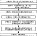
在普通的金属线接合系统中,通常,在金属线/接合工具和接触件之间建立一定程度的接触之后,接合能量(例如超声能量)被施加,将与该接触件形成接合。如果当接触件(例如引线框的引线)没有被下压(pinned down)时施加接合能量,会形成不适当的接合。具体的,震动和相关的问题会导致第二接合之后的过度易碎的(squashed)接合、短的金属线尾部长度等。In conventional wire bonding systems, typically after a certain degree of contact is established between the wire/bonding tool and the contact, bonding energy (eg ultrasonic energy) is applied which will form a bond with the contact. If bonding energy is applied when the contacts (eg, leads of a lead frame) are not pinned down, an improper bond may form. Specifically, vibration and related problems can lead to excessively squashed bonds after the second bond, short wire tail lengths, and the like.
因此,需要提供一种接合能量施加、接合力施加的改进方法以及相关的引线接合方法。Accordingly, there is a need to provide improved methods of bonding energy application, bonding force application, and related wire bonding methods.
发明内容Contents of the invention
根据本发明典型实施例,提供一种施加接合能量的方法,从而利用金属线接合机在金属线的一部分和接合位置的接触件之间形成接合。该方法包括:(1)将接合工具朝着接触件移动;(2)检测接触件的一部分何时被压靠在金属线接合机的装置支撑表面(例如加热模块)上;(3)施加接合能量给接触件的该部分,从而在接触件和金属线的该部分之间形成接合(例如施加接合能量给金属线以及接触件的该部分处的接合表面从而形成接合)。According to an exemplary embodiment of the present invention, there is provided a method of applying bonding energy to form a bond between a portion of a wire and a contact at a bonding location using a wire bonding machine. The method includes: (1) moving a bonding tool toward the contact; (2) detecting when a portion of the contact is pressed against a device support surface (e.g., a heating block) of a wire bonding machine; (3) applying the bond Energy is applied to the portion of the contact to form a bond between the contact and the portion of the wire (eg, bonding energy is applied to the wire and a bonding surface at the portion of the contact to form a bond).
根据另一个典型实施例,提供一种形成金属线环的方法,从而利用金属线接合机提供半导体装置的第一接合位置和第二接合位置之间的互连。该方法包括:(1)在第一接合位置处利用接合工具形成第一接合,从而与接合工具相连的金属线与第一接合连续;(2)将金属线的长度从第一接合位置朝着第二接合位置延伸;和(3)在第二接合位置处形成第二接合,从而金属线从第一接合部延伸到第二接合部。步骤(3)包括:(a)将接合工具朝着第二接合位置处的接触件移动,(b)检测接触件的一部分何时压靠在金属线接合机的装置支撑表面上;和(c)施加接合能量给接触件的该部分,从而接合形成在接触件和金属线之间。该方法还包括:(4)切断金属线,从而连接在接合工具中的金属线的长度从步骤(1)、(2)、(3)中形成的金属线环分开。According to another exemplary embodiment, a method of forming a wire loop to provide interconnection between a first bonding location and a second bonding location of a semiconductor device using a wire bonding machine is provided. The method includes: (1) forming a first bond with a bonding tool at a first bonding location such that a wire connected to the bonding tool is continuous with the first bond; (2) extending a length of the wire from the first bonding location toward The second bond location extends; and (3) forming a second bond at the second bond location such that the wire extends from the first bond to the second bond. Step (3) includes: (a) moving the bonding tool toward the contact at the second bonding location, (b) detecting when a portion of the contact is pressed against a device support surface of the wire bonding machine; and (c ) applies bonding energy to the portion of the contact such that a bond is formed between the contact and the wire. The method further includes: (4) cutting the wire such that the length of the wire connected in the bonding tool is separated from the wire loop formed in steps (1), (2), and (3).
根据另一个实施例,提供一种确定接合力的方法,该接合力用于利用金属线接合机将金属线的一部分接合到接合接触件。该方法包括:(1)移动工具以接触将被接合的装置的接合接触件的一部分,该工具施加初始力给接合接触件;(2)增加通过工具施加给接合接触件的该部分的力,直到接合接触件的该部分被压靠在金属线接合机的装置支撑表面;和(3)存储施加给接合接触件的该部分的力的值,接合接触件通过该力被压靠在金属线接合机的装置支撑表面上。According to another embodiment, a method of determining a bonding force for bonding a portion of a wire to a bonding contact using a wire bonding machine is provided. The method includes: (1) moving a tool to contact a portion of a bonding contact of a device to be bonded, the tool applying an initial force to the bonding contact; (2) increasing the force applied by the tool to the portion of the bonding contact, until the portion of the bonded contact is pressed against the device support surface of the wire bonding machine; and (3) storing the value of the force applied to the portion of the bonded contact by which the bonded contact is pressed against the wire The device of the bonding machine is on a support surface.
根据另一个典型实施例,提供一种利用金属线接合机形成金属线环的方法,从而提供半导体装置的第一接合位置和第二接合位置之间的互连。该方法包括:(1)在第一接合位置处利用接合工具形成第一接合,从而与接合工具连接的金属线与第一接合部连续;(2)将金属线的长度从第一接合位置朝着第二接合位置延伸;和(3)在第二接合位置处在接触件的一部分处形成第二接合,从而金属线从第一接合部连续延伸到第二接合部。步骤(3)包括:(a)确定接合力的值,该接合力将接合接触件的该部分压靠在金属线接合机的装置支撑表面上,(b)施加总的接合力给接合接触件的该部分,总的接合力大于或等于步骤(a)中确定的接合力值,(c)施加接合能量给接合接触件,从而形成第二接合部。该方法还包括(4)切断金属线,从而接合工具中连接的金属线的长度从步骤(1)、(2)、(3)中形成的金属线环分开。According to another exemplary embodiment, a method of forming a wire loop using a wire bonding machine to provide an interconnection between a first bonding location and a second bonding location of a semiconductor device is provided. The method includes: (1) forming a first bond with a bonding tool at a first bonding position, so that the metal wire connected to the bonding tool is continuous with the first bonding portion; (2) extending the length of the metal wire from the first bonding position toward and (3) forming a second bond at a portion of the contact at the second bond position such that the wire extends continuously from the first bond to the second bond. Step (3) includes: (a) determining the value of the engagement force that presses the portion of the engagement contact against the device support surface of the wire bonding machine, (b) applying the total engagement force to the engagement contact For the portion, the total engagement force is greater than or equal to the engagement force value determined in step (a), (c) applying engagement energy to the engagement contacts, thereby forming a second engagement portion. The method also includes (4) cutting the wire such that the length of wire connected in the bonding tool is separated from the wire loop formed in steps (1), (2), (3).
本发明的方法还可实现为一设备(例如作为金属线接合机的智能的一部分),或者在计算机可读载体上的计算机程序指令(例如计算机可读的载体,用于与金属线接合机相连)。The method of the present invention may also be implemented as an apparatus (e.g. as part of the intelligence of a wire bonding machine), or as computer program instructions on a computer readable carrier (e.g. a computer readable carrier for use in connection with a wire bonding machine) ).
附图说明Description of drawings
结合附图,通过下面的详细描述,本发明更容易理解。需要强调,根据常识,附图的各个特征不是成比例的。相反,各种特征的尺寸可以任意扩大或者缩小,从而更加清楚。附图中包括:The present invention can be understood more easily through the following detailed description in conjunction with the accompanying drawings. It is emphasized that, according to common sense, the various features of the drawings are not to scale. On the contrary, the dimensions of various features may be arbitrarily expanded or reduced for clarity. Included in the drawings are:
图1A是根据本发明典型实施例在下降到第二接合部过程中金属线环的侧面剖视图;1A is a side cross-sectional view of a wire loop during descent to a second junction according to an exemplary embodiment of the present invention;
图1B是根据本发明典型实施例的图1A的一部分的详细视图,示出了接合工具,接合工具将接触件压靠在金属线接合机的装置支撑表面上;1B is a detailed view of a portion of FIG. 1A showing a bonding tool pressing a contact against a device support surface of a wire bonding machine in accordance with an exemplary embodiment of the present invention;
图2A的流程图示出了根据本发明典型实施例施加接合能量的方法,从而在金属线的一部分和接合位置的接触件之间形成接合;2A is a flow diagram illustrating a method of applying bonding energy to form a bond between a portion of a metal line and a contact at a bonding location in accordance with an exemplary embodiment of the present invention;
图2B的流程图示出了根据本发明的典型实施例形成金属线环的方法,从而提供半导体装置的第一接合位置和第二接合位置之间的互连;2B is a flowchart illustrating a method of forming a metal wire loop to provide interconnection between a first bonding location and a second bonding location of a semiconductor device according to an exemplary embodiment of the present invention;
图3A的流程图示出了根据本发明典型实施例利用系统阻抗变化的方法,从而检测接触件的一部分何时被压靠在金属线接合机的装置支撑表面上;3A is a flowchart illustrating a method of utilizing a change in system impedance to detect when a portion of a contact is pressed against a device support surface of a wire bonding machine in accordance with an exemplary embodiment of the present invention;
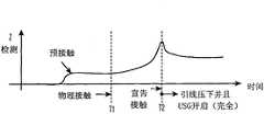
图3B是根据本发明典型实施例接合工具朝着接触件的运动的时间图,用于解释图3A的方法;3B is a timing diagram of the movement of a bonding tool toward a contact for explaining the method of FIG. 3A in accordance with an exemplary embodiment of the present invention;
图4A的流程图示出了根据本发明典型实施例的另一方法,检测接触件的一部分何时被压靠在金属线接合机的装置支撑表面上;4A is a flowchart illustrating another method of detecting when a portion of a contact is pressed against a device support surface of a wire bonding machine, according to an exemplary embodiment of the present invention;
图4B是根据本发明典型实施例朝着接触件运动过程中接合工具的速度和力的时间图,用于解释图4A的方法,;FIG. 4B is a time diagram of the velocity and force of the engagement tool during movement toward the contact, for explaining the method of FIG. 4A , according to an exemplary embodiment of the present invention;
图5A是根据本发明典型实施例半导体装置的三个相邻接触件、与接触件接触的装置夹具的一部分的部分俯视图,;5A is a partial top view of three adjacent contacts of a semiconductor device according to an exemplary embodiment of the present invention, a portion of a device fixture in contact with the contacts;
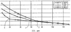
图5B的图形示出了根据本发明典型实施例的对于图5A所示的三个相邻接触件的力相对于竖直位置的数据;Figure 5B is a graph showing force versus vertical position data for the three adjacent contacts shown in Figure 5A, according to an exemplary embodiment of the present invention;
图6是根据本发明典型实施例半导体装置的接触件和装置夹具的一部分的部分侧视图;6 is a partial side view of a portion of a contact and a device fixture of a semiconductor device according to an exemplary embodiment of the present invention;
图7A的流程图示出了根据本发明典型实施例的一方法,确定用于将金属线的一部分接合到接合接触件的接合力;和7A is a flowchart illustrating a method for determining a bonding force for bonding a portion of a metal wire to a bonding contact, according to an exemplary embodiment of the present invention; and
图7B的流程图示出了根据本发明典型实施例的形成金属线环的方法,以提供半导体装置的第一接合位置和第二接合位置之间的互连。FIG. 7B is a flowchart illustrating a method of forming a metal wire loop to provide interconnection between a first bonding location and a second bonding location of a semiconductor device according to an exemplary embodiment of the present invention.
具体实施方式Detailed ways
在某些普通的金属线接合应用中,接合能量(例如超声波能量等)和接合力在“开环”过程中被施加。具体的,在(1)工具/金属线和(2)金属线将接合到其处的接触件之间检测到物理接触之后施加接合能量。In some common wire bonding applications, bonding energy (eg, ultrasonic energy, etc.) and bonding force are applied in an "open loop" process. Specifically, the bonding energy is applied after physical contact is detected between (1) the tool/wire and (2) the contact to which the wire is to be bonded.
根据本发明某些典型实施例,给接合能量提供“闭环”方法(例如超声波能量,热超声能量,热压能量等)和/或接合力施加。例如,在接触件的一部分(金属线接合将形成到其处的接触件的部分)被压靠在金属线接合机的装置支撑表面(例如,加热块,或者其它表面,接触件应当被压靠在其上)上之后,接合能量将被开启。被压靠在金属线接合机的装置支撑表面上的接触件的该部分的适合状态可称为“下压(pinned down)”或者“完全向下”位置。这种状态(即接触件的该部分被压靠在金属线接合机的装置支撑表面上)可以利用多种技术中的任一种来检测。某些典型的技术在这里描述,但是本发明不限于这些典型技术。According to certain exemplary embodiments of the present invention, a "closed loop" approach to bonding energy (eg, ultrasonic energy, thermosonic energy, thermocompression energy, etc.) and/or bonding force application is provided. For example, where a portion of the contact (the portion of the contact to which the wire bond will be formed) is pressed against a device support surface (e.g., a heat block, or other surface) of a wire bonding machine, the contact should be pressed against After on) the engagement power will be turned on. The fit state of the portion of the contact pressed against the device support surface of the wire bonding machine may be referred to as a "pinned down" or "fully down" position. This condition (ie, the portion of the contact being pressed against the device support surface of the wire bonding machine) can be detected using any of a number of techniques. Certain exemplary techniques are described here, but the present invention is not limited to these exemplary techniques.
如下面详细描述的,用于检测接触件的一部分何时被压靠在金属线接合机的装置支撑表面上的典型技术包括:(1)检测接合工具的竖直位置何时处于预定位置;(2)检测换能器(transducer)的阻抗特性何时达到预定水平;(3)确定(a)接合力和(b)接合工具的速度中的至少一个何时达到预定水平;(4)检测换能器的共振何时达到预定水平;和(5)检测施加到接触件的该部分的力何时达到阈值力。通过在确保接触件处于适当位置之后施加接合能量(例如超声能量),共振问题趋向于基本减轻,从而改善了穿过多个接合位置形成的接合的均匀性,改善了形成的接合的质量,改善了接合的装置的生产效率,并且降低了金属线接合机的操作者提供的辅助比率。As described in detail below, typical techniques for detecting when a portion of a contact is pressed against a device support surface of a wire bonding machine include: (1) detecting when the vertical position of the bonding tool is in a predetermined position; ( 2) detecting when an impedance characteristic of a transducer reaches a predetermined level; (3) determining when at least one of (a) the engagement force and (b) the speed of the engagement tool reaches a predetermined level; (4) detecting and (5) detecting when the force applied to the portion of the contact reaches a threshold force. By applying bonding energy (such as ultrasonic energy) after ensuring that the contacts are in place, resonance problems tend to be substantially mitigated, thereby improving the uniformity of the bond formed across multiple bond locations, improving the quality of the bond formed, improving This reduces the productivity of the bonded device and reduces the rate of assistance provided by the operator of the wire bonding machine.
如上所述,检测接触件的该部分何时被压靠在金属线接合机的装置支撑表面上的典型方法是检测施加到接触件的该部分的力何时达到阈值力。这种阈值力可以与用于将接触件的该部分压靠在装置支撑表面上的力(例如销力)相关。因此,根据本发明的某些典型实施例,销力的校准完成,从而,销力(例如,用于将接触件的该部分压靠在装置支撑表面上的力)对于多个接触件(例如,引线框的引线的各部分)中的每个被测量。销力校准的结果可用于多种技术中的任一个,例如:(1)预测何时某些销力测量(例如多个引线的销力测量中过大的变化)会显示出装置夹持问题(例如部件问题,安装问题等)或者机器设置问题;和(2)使用销力测量连同设定接合参数(例如施加到每个接触件的接合力可以至少等于测量的销力,施加到每个接触件的接合力可以等于对于该接触件的测量的销力加上一个偏移量,施加到每个接触件的接合力可以等于多个接触件的最大测得的销力加上偏移量(offset)等)。As noted above, a typical method of detecting when the portion of the contact is pressed against the device support surface of the wire bonding machine is to detect when the force applied to the portion of the contact reaches a threshold force. Such a threshold force may be related to the force (eg pin force) used to press the portion of the contact against the device support surface. Thus, according to some exemplary embodiments of the present invention, calibration of the pin force is accomplished such that the pin force (eg, the force used to press the portion of the contact against the device support surface) is relatively stable for a plurality of contacts (eg, , each portion of the lead of the leadframe) is measured for each. The results of the pin force calibration can be used in any of a variety of techniques, such as: (1) predicting when certain pin force measurements, such as excessive variation in pin force measurements across multiple leads, will indicate device clamping issues (e.g. component issues, installation issues, etc.) or machine setup issues; and (2) use pin force measurements in conjunction with setting engagement parameters (e.g. the engagement force applied to each contact can be at least equal to the measured pin force applied to each The engagement force for a contact may be equal to the measured pin force for that contact plus an offset, and the engagement force applied to each contact may be equal to the maximum measured pin force for the plurality of contacts plus the offset (offset) etc).
图1A是金属线环100的部分侧视图,其提供(1)半导体管芯102的管芯焊盘和(2)引线框100的引线100a之间的电互连。具体的,接合工具106(例如毛细管工具)用于将接合工具106中连接(engaged)的金属线108的长度在(1)半导体管芯102的管芯焊盘和(2)引线框100的引线100a之间延伸。如本领域技术人员公知的,半导体管芯102安装到引线框100,其包括引线100a。引线框100定位在金属线接合机的装置支撑表面112上(例如加热块112或者另一个装置支撑表面)。当然,图1A中仅示出了引线框100的一部分(以及引线框100的引线100a的仅一部分),半导体管芯102和装置支撑表面112。引线100a利用装置夹持件104夹持(图1A仅示出了装置夹持件104的一小部分)。如图1A,金属线环110的端部将接合到其处的引线100a的部分(图1A所示的实例中的第二接合)没有被压靠在装置支撑表面112上。弯折远离装置支撑表面112的引线100a的该部分可以通过例如高装置夹持力、窗口夹持几何轮廓的结果(window clamp geometry issues)、加热、和/或毛边(burr)或者其它污染物等其它可能的原因造成。在用于施加接合能量的普通的“开环”系统中,可以在当与引线100a的该部分接触时施加接合能量,与下面事实无关:它没有被压靠在装置支撑表面112上。如上所述,将接合能量施加到引线例如图1A所示的引线100a会导致振动以及相关问题,从而导致过度易碎的接合、短的尾部等。1A is a partial side view of a
根据本发明某些典型实施例,直到接触件(例如引线100a)被压靠在金属线接合机的装置支撑表面上(例如装置支撑表面112),接合能量才被施加以形成接合(例如第一接合部,第二接合部等)。因此,图1B示出了接合工具106下降,直到引线100a的相关部分(即图1A所示的第二接合将形成在其上的部分)被压靠在图1B所示的装置支撑表面112上。According to some exemplary embodiments of the invention, bonding energy is not applied to form a bond (e.g., the first junction, second junction, etc.). Accordingly, FIG. 1B shows that the
图2A-2B是根据本发明某些典型实施例的流程图。本领域技术人员容易理解,流程图中包括的某些步骤可以省略;某些另外的步骤可以增加;并且步骤的顺序可以与所示的不同。2A-2B are flow diagrams according to some exemplary embodiments of the invention. Those skilled in the art will readily understand that certain steps included in the flowcharts may be omitted; certain additional steps may be added; and the order of the steps may be different than shown.
图2A的流程图示出了施加接合能量的方法,从而在金属线的一部分和接合位置的接触件之间利用根据本发明典型实施例的金属线接合机形成接合。例如,参考图1A,图2A的方法可用于施加接合能量以在(1)金属线108的一部分和(2)引线框100的引线100a之间形成接合部。在步骤200,接合工具(例如接合工具106)朝着接触件(例如引线100a)移动。在步骤202,完成下列检测过程:检测接触件的一部分何时被压靠在金属线接合机的装置支撑表面上(例如检测引线100a的所示部分何时被压靠在图1B的装置支撑表面112上)。在步骤204,接合能量(例如超声波能量)施加到接触件的该部分,从而接合(例如图1A-1B所示的第二接合部)形成在接触件和金属线的该部分之间。2A is a flow diagram illustrating a method of applying bonding energy to form a bond between a portion of a wire and a contact at a bonding location using a wire bonding machine according to an exemplary embodiment of the present invention. For example, referring to FIG. 1A , the method of FIG. 2A may be used to apply bonding energy to form a bond between (1) a portion of
步骤202可以利用多种技术中的任一种完成。例如,检测步骤可包括检测接合工具的竖直位置何时处于预定位置。金属线接合领域技术人员知道,编码器系统,视觉系统等可用于确定接合工具何时处于下面的高度处,其中,接触件(例如引线100a)处于“完全下部”或者“下压”位置,如图1B所示。这个位置可被记录从而在下降以形成接合的过程中(例如图1B所示的第二接合),可以知道这个位置已经达到,从而检测接触件被压靠在金属线接合机的装置支撑表面上。Step 202 can be accomplished using any of a variety of techniques. For example, the detecting step may comprise detecting when the vertical position of the bonding tool is in a predetermined position. Those skilled in the art of wire bonding know that encoder systems, vision systems, etc. can be used to determine when the bonding tool is at a lower level where the contact (e.g., lead 100a) is in a "full down" or "depressed" position, such as Figure 1B. This position can be recorded so that during descent to form a bond (such as the second bond shown in FIG. 1B ), it is known that this position has been reached so that the detection contact is pressed against the device support surface of the wire bonding machine .
可用于检测接触件何时压靠在装置支撑表面上的另一个技术是检测换能器(接合工具连接到其处)的阻抗特性何时达到了预定水平。例如,这种阻抗特性可包括阻抗大小阈值,和阻抗大小变化(或者变化率),阻抗相位阈值或者变化(或者变化率),锁定频率变化等。这种检测策略的最具体的实例将参考图3A和3B解释。Another technique that can be used to detect when a contact is pressed against a device support surface is to detect when the impedance characteristic of the transducer (to which the bonding tool is connected) has reached a predetermined level. For example, such impedance characteristics may include impedance magnitude thresholds, and impedance magnitude changes (or rates of change), impedance phase thresholds or changes (or rates of change), lock frequency changes, and the like. The most specific example of this detection strategy will be explained with reference to Figures 3A and 3B.
可用于检测接触件何时压靠在装置支撑表面上的另一种技术是确定(a)接合力和(b)接合工具的速度中的至少一个何时达到预定水平。这种检测策略的更具体的实施例将参考图4A-4B详细描述。Another technique that may be used to detect when a contact is pressed against a device support surface is to determine when at least one of (a) the engagement force and (b) the speed of the engagement tool reaches a predetermined level. A more specific example of such a detection strategy will be described in detail with reference to Figures 4A-4B.
可用于检测接触件何时压靠在装置支撑表面上的技术是检测换能器(接合工具连接到其处)的共振何时达到预定水平。A technique that can be used to detect when a contact is pressed against a device support surface is to detect when the resonance of the transducer (to which the bonding tool is attached) reaches a predetermined level.
可用于检测接触件何时压靠在装置支撑表面上的另一种技术是(1)确定将把接触件的该部分压靠在金属线接合机的装置支撑表面上的力值和(2)检测施加到接触件的该部分的力何时达到阈值力,阈值力大于或等于步骤(1)确定的力值。这种技术可以对于半导体装置的多个接触件(例如引线框的引线)中的每一个重复,从而阈值力可以被选择成对于每个接触件都相同(从而选择的阈值力大于或等于对于多个接触件中的任一个在步骤(1)中确定的最大力值),或者阈值力可以对于多个接触件中的每一个单独地选择。阈值力对于多个接触件中的每一个都相同,或者对于多个接触件中的每一个都单独地选择/确定,可以以多种方式选择。例如,阈值力可以选择成等于对于多个接触件中的任一个在步骤(1)中确定的最大力值,或者可以是对于多个接触件中任一个在步骤(1)确定的最大值加上预定力偏移值。另一个实例中,阈值力对于多个接触件中的每一个可以独立选择,从而对于多个接触件中的每一个选择的阈值力大于或等于步骤(1)中对于多个接触件中相应一个确定的力值,或者可以选择成等于步骤(1)中对于多个接触件中的那一个确定的力值加上预定力偏移值。Another technique that can be used to detect when the contact is pressed against the device support surface is to (1) determine the amount of force that will press that portion of the contact against the device support surface of the wire bonding machine and (2) It is detected when the force applied to the portion of the contact reaches a threshold force greater than or equal to the force value determined in step (1). This technique can be repeated for each of multiple contacts of a semiconductor device (such as leads of a lead frame), so that the threshold force can be chosen to be the same for each contact (so that the selected threshold force is greater than or equal to that for multiple contacts). the maximum force value determined in step (1) for any one of the contacts), or the threshold force can be selected individually for each of the plurality of contacts. The threshold force is the same for each of the plurality of contacts, or is selected/determined individually for each of the plurality of contacts, and can be selected in a number of ways. For example, the threshold force may be selected to be equal to the maximum force value determined in step (1) for any of the plurality of contacts, or may be the maximum value determined in step (1) for any of the plurality of contacts plus Upper preset force offset value. In another example, the threshold force may be independently selected for each of the plurality of contacts such that the threshold force selected for each of the plurality of contacts is greater than or equal to the corresponding one of the plurality of contacts in step (1). The determined force value, or may be selected to be equal to the determined force value for the one of the plurality of contacts in step (1) plus a predetermined force offset value.
另外,这里描述的方法可以用于接触件(例如引线框的引线),其中多个接合(例如多个第二接合)形成在同一个接触件的不同部分上。Additionally, the methods described herein may be used with contacts (eg, leads of a lead frame) where multiple bonds (eg, multiple second bonds) are formed on different portions of the same contact.
参考图2B,所提供的流程图示出了根据本发明典型实施例的形成金属线环的方法,以提供半导体装置的第一接合位置和第二接合位置之间的互连。在步骤250,第一接合利用接合工具形成在第一接合位置处,从而与接合工具相连的金属线与第一接合连续。例如,这种第一接合在图1A中示为第一接合110a。在步骤252,金属线的长度从第一接合位置朝着第二接合位置延伸。例如,金属线的这种长度在图1A中示为长度110b。在步骤254,第二接合形成在第二接合位置处,从而金属线从第一接合连续延伸到第二接合。例如,第二接合利用金属线环110的部分110c形成,其中金属线部分110c接合到接触件100a(例如引线100a)。Referring to FIG. 2B , a flowchart is provided illustrating a method of forming a metal wire loop to provide interconnection between a first bonding location and a second bonding location of a semiconductor device in accordance with an exemplary embodiment of the present invention. At step 250, a first bond is formed at a first bond location using a bonding tool such that a wire connected to the bonding tool is continuous with the first bond. For example, such a first engagement is shown in FIG. 1A as
步骤254包括多个步骤(或者子步骤)。在步骤254A,接合工具朝着第二接合位置处的接触件移动(例如,这种移动动作在图1B中示出,示出了虚线的接合工具106,在接触件100a上方,以及实线的接合工具106,其已经被向下朝着接触件100a移动(并且在这种情况中相接触)。在步骤254B,检测接触件的一部分何时压靠在金属线接合机的装置支撑表面上。在步骤254C,接合能量施加到接触件的该部分,从而接合形成在接触件和金属线之间。Step 254 includes multiple steps (or sub-steps). At step 254A, the bonding tool is moved toward the contact at the second bonding position (for example, this movement is illustrated in FIG. The
在步骤256,金属线被切断,从而接合工具中连接的金属线的长度从在步骤250、252、254中形成的金属线环分开。At step 256 the wire is severed such that the length of wire connected in the bonding tool is separated from the loop of wire formed in steps 250 , 252 , 254 .
当然,步骤254(包括步骤254A、254B和254C)可以利用多个方法中的任一种完成,包括本申请描述的那些,并且包括相对于图2A方法描述过的那些。Of course, step 254 (including steps 254A, 254B, and 254C) may be accomplished using any of a number of methods, including those described herein, and including those described with respect to the method of FIG. 2A.
如上所述,根据本发明,许多不同的方法可以使用,从而检测接触件的一部分何时被压靠在金属线接合机的装置支撑表面上。图3A-3B用于示出这种检测技术的一种典型方法。As mentioned above, according to the present invention, a number of different methods can be used to detect when a portion of a contact is pressed against a device support surface of a wire bonding machine. Figures 3A-3B are used to illustrate a typical approach to this detection technique.
图3A的流程图示出了检测接触件的一部分何时被压靠在金属线接合机的装置支撑表面上的方法。本领域技术人员应当理解,图3A中包括的某些步骤可以省略,某些另外的步骤可以增加,并且步骤顺序可以与所示的不同。在步骤300,该方法(例如,算法在计算机系统上运行,该系统与金属线接合机相连)开始。在步骤302,确定接合工具是否处于恒定/受控速度模式(即CV模式)。本领域技术人员知道,CV模式是随着它朝着接合位置降低、接合工具的运动循环的一部分。如果还没有进入CV模式(在步骤302,“否”),那么步骤302重复。如果已经进入了CV模式(在步骤302,“是”),那么方法继续到步骤304。根据这个具体的实例,直到CV模式已经进入,步骤304处的阻抗检测才开始;然而,这仅是一个实例。阻抗检测可以是恒定启动,或者这种启动可以被关联到某些其它测量(例如,与接触件的初始物理接触)。The flowchart of Figure 3A shows a method of detecting when a portion of a contact is pressed against a device support surface of a wire bonding machine. Those skilled in the art will understand that certain steps included in FIG. 3A may be omitted, certain additional steps may be added, and the order of the steps may be different from that shown. At step 300, the method (eg, an algorithm running on a computer system coupled to a wire bonding machine) begins. At step 302, it is determined whether the engaging tool is in a constant/controlled speed mode (ie, CV mode). Those skilled in the art know that the CV mode is part of the motion cycle of the bonding tool as it is lowered towards the bonding position. If CV mode has not been entered ("No" at step 302), then step 302 repeats. If CV mode has been entered (“YES” at step 302 ), the method continues to step 304 . According to this particular example, impedance detection at step 304 does not begin until CV mode has been entered; however, this is only one example. Impedance detection may be a constant activation, or such activation may be correlated to some other measurement (eg, initial physical contact with a contact).
在步骤304,阻抗检测开始,并且检测启动计时器在t=0时开始。本领域技术人员知道,这种阻抗检测可以利用低水平的超声波能量(即低USG电流),其可以在CV模式过程中施加。当施加这种低水平电流时,换能器的阻抗(或者与阻抗相关的一些特征)被监测,并且当检测到这个阻抗的变化超过指定的阈值(IT)时,宣告接触,并且通常的接触能量(例如超声波能量)可施加。如上所述,监测的阻抗特性可以是多种特征中的任一个,包括例如阻抗大小阈值,阻抗大小变化(或者变化率),阻抗相位阈值或者变化(或者变化率),锁定频率变化等。In step 304, the impedance detection is started and a detection start timer is started at t=0. Those skilled in the art know that such impedance detection can utilize low levels of ultrasound energy (ie, low USG current), which can be applied during CV mode. When this low level of current is applied, the impedance of the transducer (or some characteristic related to the impedance) is monitored, and when a change in this impedance is detected above a specified threshold (IT ), contact is declared, and the usual Contact energy, such as ultrasonic energy, can be applied. As noted above, the monitored impedance characteristic may be any of a variety of characteristics including, for example, impedance magnitude threshold, impedance magnitude change (or rate of change), impedance phase threshold or change (or rate of change), lock frequency change, and the like.
参考图3A,在步骤306,确定是否已经检测到预定阻抗变化。如果预定阻抗变化检测到(在步骤306,“是”),接合能量(例如超声能量或者USG)在步骤310被开启,从而可以形成接合。如果没有检测到预定阻抗变化(在步骤306,“否”),在步骤308检查时间是否终止(例如,在t=0之后预定的时间段)。如果时间没有终止(步骤308,“否”的结果),给定时器增加增量(t=t+1),并且过程返回到步骤306,用于另一个检查,即预定阻抗变化是否检测到。如果时间终止(在步骤308,“是”的答案),然后接合能量(例如超声能量或者USG)在步骤310被开启,从而可以形成接合。这个典型实施例中,假设如果时间在步骤308终止,接触件的相关部分已经被压靠在金属线接合机的装置支撑表面上,并且接合过程可以进行(与不适当地中断接合过程相反,或者可以更好地看做继续过程,在假设接触件的相关部分已经被压靠在装置支撑表面上的基础上)。在步骤312,过程(例如在金属线接合机上运行的算法)已经完成。当然,图3A的方法可以对于半导体装置的多个接触件重复,或者对于单个接触件重复多次(其中这种单个接触件可以构造成接合多次)。Referring to FIG. 3A, at step 306, it is determined whether a predetermined impedance change has been detected. If a predetermined impedance change is detected ("YES" at step 306), bonding energy (eg, ultrasonic energy or USG) is turned on at step 310 so that a bond can be formed. If no predetermined impedance change is detected ("No" at step 306), it is checked at step 308 whether the time has elapsed (eg, after a predetermined period of time after t=0). If the time has not expired (step 308, "no" outcome), the timer is incremented (t=t+1) and the process returns to step 306 for another check, whether a predetermined impedance change is detected. If the time expires ("yes" answer at step 308), then bonding energy (eg, ultrasonic energy or USG) is turned on at step 310 so that a bond can be formed. In this exemplary embodiment, it is assumed that if time expires at step 308, the relevant portion of the contact has been pressed against the device support surface of the wire bonding machine and the bonding process can proceed (as opposed to unduly interrupting the bonding process, or It can be better seen as a continuation of the process, on the assumption that the relevant part of the contact has been pressed against the device support surface). At step 312, a process (eg, an algorithm running on a wire bonding machine) has completed. Of course, the method of FIG. 3A may be repeated for multiple contacts of a semiconductor device, or multiple times for a single contact (where such a single contact may be configured to engage multiple times).
图3B是接合工具朝着接触件运动的时刻图,用于解释图3A的方法。具体的,y轴被标为“Z检测”,并且涉及到阻抗特性,阻抗特性被监测用于阈值或者阈值变化。X轴是时间。在时间“T1”之前是预接触期间,其中接合工具还没有接触所述接触件(例如引线)。在时间T1,接合工具已经与接触件(例如引线)物理接触,并且在从T1到T2具有阻抗特性上的变化。在时间T2,接触件已经被压靠到金属线接合机的装置支撑表面上(例如,引线被“压下”),如阻抗检测策略明显可见的,其检测预定阻抗阈值或者阈值变化已经满足。FIG. 3B is a timing diagram of the movement of the bonding tool toward the contact to explain the method of FIG. 3A . Specifically, the y-axis is labeled "Z Detection" and relates to impedance characteristics that are monitored for thresholds or threshold changes. The x-axis is time. Prior to time "T1" is a pre-contacting period in which the bonding tool has not yet contacted the contacts (eg, leads). At time T1, the bonding tool has made physical contact with the contact (eg, lead) and has a change in impedance characteristic from T1 to T2. At time T2, the contact has been pressed against the device support surface of the wire bonding machine (eg, the wire is "depressed"), as evident from the impedance detection strategy, which detects that a predetermined impedance threshold or threshold change has been met.
图4A的流程图示出了检测接触件的一部分何时被压靠在金属线接合机的装置支撑表面上的另一个典型方法。这个方法中,确定(a)接合力和(b)接合工具的速度中的至少一个是否达到预定水平。在图4A-4B的实例中,相对于接合力和速度描述了所述判定;但是,应当理解,在检测接触件的一部分何时被压靠在金属线接合机的装置支撑表面上时,其中一个特性可被检测。本领域技术人员理解,图4A中的某些步骤可省略,某些另外的步骤可以增加,步骤的顺序可以与所示的有所变化。The flowchart of FIG. 4A illustrates another exemplary method of detecting when a portion of a contact is pressed against a device support surface of a wire bonding machine. In this method, it is determined whether at least one of (a) the joining force and (b) the speed of the joining tool reaches a predetermined level. In the example of FIGS. 4A-4B , the determination is described with respect to bonding force and speed; however, it should be understood that when detecting when a portion of a contact is pressed against a device support surface of a wire bonding machine, where A characteristic can be detected. Those skilled in the art understand that some steps in FIG. 4A can be omitted, some additional steps can be added, and the order of the steps can be changed from what is shown.
在步骤400,该方法启动(即在计算机系统上运行的算法,该计算机与金属线接合机相关联)。在步骤402,接合工具朝着接合位置(例如接触件,诸如引线框的引线)移动。在步骤404,确定在接合工具和接触件(例如引线)之间是否已经检测到接触。如果接触还没有被检测到(在步骤404“否”),那么步骤404重复。如果接触已经检测到(在步骤404“是”),那么方法继续到步骤406。At step 400, the method is initiated (ie, an algorithm running on a computer system associated with a wire bonding machine). At step 402, a bonding tool is moved toward a bonding location (eg, a contact, such as a lead of a lead frame). At step 404, it is determined whether contact has been detected between the bonding tool and the contact (eg, lead). If no contact has been detected ("NO" at step 404), then step 404 repeats. If contact has been detected (“YES” at step 404 ), the method continues to step 406 .
在步骤406,定时器在t=0启动。在步骤408,确定速度和/或力阈值是否已经满足。如果速度和/或力阈值已经满足(在步骤408“是”),接合能量(例如超声能量或者USG)在步骤412被开启,从而可以形成接合。如果速度和/或力阈值还没满足(在步骤408,“否”的回答),那么在步骤410检查看看时间是否终止(例如,t=0之后的预定时间段)。如果时间还没有终止(在步骤410,“否”的回答),增量被增加给定时器(t=t+1),并且过程回到步骤408用于另一个检查,检查速度和/或力阈值是否已经满足。如果时间终止(在步骤410“是”的回答),那么接合能量(例如超声能量或者USG)在步骤412开启,从而可以形成接合。在这个典型实施例中,假设如果时间在步骤412终止,接触件的相关部分已经被压靠在金属线接合机的装置支撑表面上,并且接合过程可以进行(或者更好地可以看做是在下面的假设上继续该过程,即接触件的相关部分已经被压靠在装置支撑表面上,与不适当地中断接合过程相反)。在步骤414,过程(例如在金属线接合机上运行的算法)已经完成。当然,图4A的方法对于半导体装置的多个接触件可以重复,或者对于单个接触件可以重复多次(其中,这种单个接触件可以构造成接合多次)。At step 406, a timer is started at t=0. At step 408, it is determined whether velocity and/or force thresholds have been met. If the velocity and/or force thresholds have been met ("YES" at step 408), bonding energy (eg, ultrasonic energy or USG) is turned on at step 412 so that a bond can be formed. If the velocity and/or force thresholds have not been met ("no" answer at step 408), then at step 410 a check is made to see if time has expired (eg, a predetermined period of time after t=0). If the time has not expired ("No" answer at step 410), the increment is added to the timer (t=t+1), and the process goes back to step 408 for another check, checking speed and/or force Whether the threshold has been met. If the time expires ("YES" answer at step 410), then bonding energy (eg, ultrasonic energy or USG) is turned on at step 412 so that a bond can be formed. In this exemplary embodiment, it is assumed that if time expires at step 412, the relevant portion of the contact has been pressed against the device support surface of the wire bonding machine and the bonding process can proceed (or better can be seen as The process continues on the assumption that the relevant portion of the contact has been pressed against the device support surface, as opposed to inappropriately interrupting the engagement process). At step 414, the process (eg, an algorithm running on the wire bonding machine) has completed. Of course, the method of FIG. 4A may be repeated for multiple contacts of a semiconductor device, or multiple times for a single contact (where such a single contact may be configured to engage multiple times).
图4B是接合工具朝着接触件运动的时刻图,用于解释图3A的方法。具体的,y轴被标为“速度”和“力”,并且它们涉及接合工具的速度以及接合工具施加给接触件的力。X轴线是时间。根据本发明典型实施例,为了确定接触件的一部分(例如将与金属线接合的接触件的相关部分)何时被压靠在金属线接合机的装置支撑表面上,速度应当基本为零(例如速度必须达到速度阈值,如图4B所示),并且施加的接合力应当达到预定阈值(例如图4B所示的力阈值)。在时间T1之前,速度和力信号都处于相对恒定状态(非常小的斜度),之后是随着时间接近T1,斜度尖锐变化。在时间T1和T2之间,速度和力信号都发生变化,但是在时间T2,两个阈值都已经满足。也就是,在时间T2之后,(1)速度信号高于速度阈值(例如,接合工具已经停止移动),并且已经稳定,并且(2)力信号高于力阈值。因此,在时间T2,接触件已经被压靠在金属线接合机的装置支撑表面上(例如,引线被“下压”),并且现在可以施加接合能量。FIG. 4B is a timing diagram of the movement of the bonding tool toward the contact to explain the method of FIG. 3A . In particular, the y-axis is labeled "Speed" and "Force" and they relate to the speed of the bonding tool and the force exerted by the bonding tool on the contact. The x-axis is time. According to an exemplary embodiment of the invention, in order to determine when a portion of a contact (e.g., the relevant portion of the contact to be bonded to a wire) is pressed against a device support surface of a wire bonding machine, the velocity should be substantially zero (e.g. The speed must reach a speed threshold, as shown in FIG. 4B ), and the applied engagement force should reach a predetermined threshold (eg, the force threshold shown in FIG. 4B ). Both velocity and force signals are relatively constant (very small slope) until time T1, followed by a sharp change in slope as time approaches T1. Between times T1 and T2, both velocity and force signals change, but at time T2, both thresholds have been met. That is, after time T2, (1) the velocity signal is above the velocity threshold (eg, the bonding tool has stopped moving) and has stabilized, and (2) the force signal is above the force threshold. Thus, at time T2, the contacts have been pressed against the device support surface of the wire bonding machine (eg, the wires are "pressed down"), and bonding energy can now be applied.
与图4A-4B的方法结合使用的接合力阈值可以是使用者限定的阈值,或者可以结合力校准测量而确定(即这样的测量,其确定多少力用于将接触件的该部分压靠在金属线接合机的装置支撑表面上)。这种接合力校准技术参考图5A-5B和图7A-7B描述。The engagement force threshold used in conjunction with the method of FIGS. 4A-4B may be a user-defined threshold, or may be determined in conjunction with a force calibration measurement (i.e. a measurement that determines how much force is used to press the portion of the contact against on the device support surface of the wire bonding machine). This engagement force calibration technique is described with reference to FIGS. 5A-5B and 7A-7B.
与图1A-1B的引线100a的一部分和装置夹持件104的侧视图相反,图5A是三个相邻引线(那些引线的部分)和装置夹持件的一部分的俯视图。具体的,图5A示出了引线框的引线10、引线11和引线12。引线(以及未示出的装置的其它的)被装置夹持件504“夹持”(图5A中,装置夹持件504的仅一小部分以块的形式示出)。同样示出的是三个金属线环506、508、510的端部。每个金属线环506、508和510已经被针脚式接合在引线10、11、12中相应一个上作为第二接合,如所示。In contrast to the side views of a portion of lead 100a and
图5B的图形示出了对于图5A的三个相邻引线的力相对于竖直位置的数据。具体的,随着接触每个引线10、11、12的接合工具竖直位置变化(随着沿着y轴的Z位置减小),施加给引线的力同样变化(沿着x轴线的力增大)。换句话说,为了继续降低工具的z位置(例如竖直位置),另外的力被施加。图5B所示的三个“曲线”均对应于其中一个引线10、11、12(图5B中的图例更为清楚)。因此,与引线10对应的曲线(图5B中的底部的曲线)在点“X“具有显著的斜度变化(即以大约20grams的力,并且在Z位置大约0.3mils)。同样,与引线11对应的曲线(图5B中的中间曲线)在点Y具有显著的斜度变化(即大约60grams的力,并且Z位置大约0.21mils)。同样,与引线12对应的曲线(图5B中的顶部的曲线)在点Z具有显著的斜度变化(即大约70grasm的力,并且Z位置大约0.20mils)。这个斜度变化基本涉及到这样的点,该点大致地从(2)需要克服某些系统部件的力(例如与接合头和加热块相关的刚性等)描绘(delineate)出(1)引线的弹性力。具体的,每个曲线的左边部分(即点X、Y和Z左边的部分)基本对应于用于克服引线弹性力的力,也就是,克服弹性力用于将引线的该部分压靠在金属线接合机的装置支撑表面(例如加热块)上(每个曲线的右边部分对应于将被克服的系统力,例如与接合头和加热块相关的刚性)。因此,为了克服引线10、11和12的弹性力,可以分别施加20、60和70grams的接合力。因此,通过施加不同的力给多个引线中的每一个,用于将引线的相关部分压靠在金属线接合机的装置支撑表面(例如加热块)上的力可以确定,例如通过确定曲线在哪个点处改变斜度。因此,可以近似的是,引线10将使用20grams的力(见图5B中点X)用于将引线10的相关部分压靠在金属线接合机的装置支撑表面(例如加热块)上。当然,这个过程可以利用计算机算法等自动进行,从而确定对于每个引线的大致的力值(例如,算法可构造成通过增量增加施加的接合力,然后确定在每个增量处的Z位置,并且最后确定引线被压靠在装置支撑表面上的点,即斜度变化的点)。另外,在实际执行金属线接合方法之前,这个过程可以对于单个过程中的每个引线重复。Figure 5B is a graph showing force versus vertical position data for three adjacent leads of Figure 5A. Specifically, as the vertical position of the bonding tool contacting each lead 10, 11, 12 changes (as the Z position along the y-axis decreases), the force applied to the leads also changes (with increasing force along the x-axis). big). In other words, to continue lowering the tool's z-position (eg, vertical position), additional force is applied. The three "curves" shown in Fig. 5B each correspond to one of the leads 10, 11, 12 (the legend in Fig. 5B is clearer). Thus, the curve corresponding to lead 10 (the bottom curve in FIG. 5B ) has a significant slope change at point "X" (ie, at about 20 grams of force, and about 0.3 mils at the Z position). Likewise, the curve corresponding to lead 11 (the middle curve in FIG. 5B ) has a significant slope change at point Y (ie, about 60 grams of force, and about 0.21 mils in Z position). Likewise, the curve corresponding to lead 12 (the top curve in FIG. 5B ) has a significant slope change at point Z (ie about 70 grains of force and about 0.20 mils in Z position). This slope change basically relates to the point that roughly delineates (1) the length of the lead from (2) the forces needed to overcome certain system components (such as stiffness associated with the bond head and heating block, etc.) Elasticity. Specifically, the left portion of each curve (ie, the portion to the left of points X, Y, and Z) corresponds substantially to the force used to overcome the elastic force of the lead, that is, to overcome the elastic force used to press that portion of the lead against the metal On the device support surface of the wire bonding machine, such as a heating block (the right part of each curve corresponds to the system forces to be overcome, such as the stiffness associated with the bonding head and heating block). Therefore, to overcome the elastic force of the leads 10, 11 and 12, a bonding force of 20, 60 and 70 grams can be applied, respectively. Thus, by applying a different force to each of the plurality of wires, the force used to press the relevant portion of the wire against a device support surface (e.g. a heating block) of a wire bonding machine can be determined, for example by determining a curve at The point at which to change the slope. Thus, it can be approximated that 20 grams of force (see point X in FIG. 5B ) will be used for the wire 10 to press the relevant portion of the wire 10 against the device support surface (eg, heating block) of the wire bonding machine. Of course, this process can be automated using computer algorithms or the like to determine approximate force values for each lead (e.g., the algorithm can be configured to increment the applied engagement force by increments and then determine the Z position at each increment , and finally determine the point at which the lead wire is pressed against the device support surface, ie the point at which the slope changes). Additionally, this process can be repeated for each wire in a single process before actually performing the wire bonding method.
与图5A中的接触件10、11和12(即引线10、11和12)的俯视图相反,图6是类似的接触件600a(即引线框的引线600a)的部分侧视图。图6还示出了装置夹持件604的一部分和金属线接合机的装置支撑表面620(例如加热块620)的一部分。图6清楚所示,引线600a的一部分被抬高到装置支撑表面620上方。由于上面的原因,在引线600a的这个部分上形成金属线接合之前,适合的是将引线600a的这部分压靠在装置支撑表面600a上。这个实例中,多个金属线接合可以形成在接触件600a的这个部分上。具体的,多个金属线接合(例如可以被针脚式接合的第二接合)可以形成在引线600a的每个区域R1、R2和R3中(即接合位置R1、R2、R3)。本领域技术人员知道,在同一个引线上形成多个金属线接合的典型应用包括堆叠管芯应用、多分层应用等。为了将接触件600a的相关部分(即部分R1、R2、R3等)压靠/下压在装置支撑表面620上,不同的力可以使用。也就是说,为了将部分R1压靠在装置支撑表面620上,与用于将部分R3压靠在装置支撑表面620上所使用的力相比,将可能使用较小的力。在某些接触件中,例如图6所示的引线600a,随着越靠近装置夹持件,用于将引线压靠在装置支撑表面上的力趋向增大。因此图6中,将接触件600a压靠在装置支撑表面620上容易在接合位置R1处使用较小的力,比接合位置R2处更小。同样,将接触件600a压靠在装置支撑表面620处容易在接合位置R2处使用较小的力,比接合位置R3处更小。记住这一点,当检测接触件的一部分何时被压靠在金属线接合机的装置支撑表面上时(例如图2A的步骤202,图2B的步骤254B等),这种检测对于接触件的不同部分(例如接合位置R1、R2和R3)可以重复。In contrast to the top view of contacts 10, 11 and 12 (ie, leads 10, 11 and 12) in FIG. 5A, FIG. 6 is a partial side view of a
图7A-7B是根据本发明某些典型实施例的流程图。本领域技术人员知道,流程图中的某些步骤可以省略,某些另外的步骤可以增加,并且步骤的顺序可以与所示的顺序有所改变。7A-7B are flowcharts in accordance with some exemplary embodiments of the invention. Those skilled in the art will appreciate that certain steps in the flowcharts may be omitted, certain additional steps may be added, and the order of the steps may be changed from that shown.
图7A的流程图示出了根据本发明典型实施例的方法,确定用于将金属线的一部分接合到接合接触件的接合力。这个方法可以与接合过程并行地进行(即力可确定用于具体的接触件,然后在确定之后连同所述接合过程被施加),或者该方法可以在接合过程之前进行(例如,可以确定对于多个接触件的力,并且然后接合过程可以在进行了确定之后完成)。在步骤700,工具被移动以接触待金属线接合的装置的接合接触件的一部分。工具向接合接触件施加初始的力。在步骤702,施加到接合接触件的该部分的力被工具增大,直到接合接触件的该部分被压靠在金属线接合机的装置支撑表面上。例如,该力可以通过增量增大(例如利用预定的力增量),直到接合接触件的该部分被压靠在金属线接合机的装置支撑表面上。FIG. 7A is a flowchart illustrating a method of determining a bonding force for bonding a portion of a metal wire to a bonding contact, according to an exemplary embodiment of the present invention. This method can be carried out in parallel with the bonding process (i.e. the force can be determined for a specific contact and then applied in conjunction with the bonding process after determination), or it can be carried out before the bonding process (e.g. it can be determined for multiple contacts, and then the engagement process can be completed after a determination has been made). At step 700, a tool is moved to contact a portion of a bonding contact of a device to be wire bonded. The tool applies an initial force to the engagement contacts. At step 702, the force applied to the portion of the bonded contact is increased by the tool until the portion of the bonded contact is pressed against a device support surface of the wire bonding machine. For example, the force may be increased by increments (eg with predetermined force increments) until the portion of the engagement contact is pressed against the device support surface of the wire bonding machine.
在步骤704,施加到接合接触件的该部分的力的值被存储在存储器中(例如,存储在金属线接合机的计算机存储器中),通过它,接合接触件被压靠在金属线接合机的装置支撑表面上。在步骤706,步骤700、702和704对于接合接触件的多个接合位置被重复(例如,图6的接触件/引线600a上的接合位置R1、R2和R3)。在步骤708,步骤700、702和704对于将被金属线接合的装置的多个接合接触件被重复(例如图5A的接触件/引线10、11和12)。At step 704, the value of the force applied to the portion of the bonded contact is stored in memory (e.g., in a computer memory of the wire bonding machine) by which the bonded contact is pressed against the wire bonding machine on the device support surface. At step 706 , steps 700 , 702 , and 704 are repeated for a plurality of bond locations of bonded contacts (eg, bond locations R1 , R2 , and R3 on contact/lead 600 a of FIG. 6 ). At step 708, steps 700, 702, and 704 are repeated for a plurality of bonding contacts of the device to be wire bonded (eg, contacts/leads 10, 11, and 12 of FIG. 5A).
如上所述,图7A所示的方法可包括另外的步骤。例如,该方法可包括下面的另外步骤:在以一定增量增大施加到接合接触件的该部分的力的步骤过程中,记录沿着基本竖直轴线的工具的多个位置中的每一个,从而多个位置中的每一个对应于施加到接合接触件的该部分的力。例如,在工具接触所述接触件之后(但是在接触件被挤压在金属线接合机的装置支撑表面上之前),工具沿着Z轴线的多个位置中的每一个可以连同被施加的相对应的力而被记录。这种类型的数据的实例在上述图5B中示出。参考图5B的引线10,第一数据点包括在大约0.6mils和大约6grams力处记录的竖直位置。图5B中引线10的第二数据点包括在大约0.48mils和大约11grams力处记录的竖直位置。例如,这个数据可用于确定曲线的斜度何时改变,如参考图5B描述的。As noted above, the method shown in FIG. 7A may include additional steps. For example, the method may comprise the further step of recording each of a plurality of positions of the tool along the substantially vertical axis during the step of increasing the force applied to the portion of the engagement contact by increments , such that each of the plurality of positions corresponds to a force applied to the portion of the engagement contact. For example, after the tool contacts the contact (but before the contact is pressed against the device support surface of the wire bonding machine), each of a plurality of positions of the tool along the Z-axis may be applied along with the corresponding The corresponding force is recorded. An example of this type of data is shown above in Figure 5B. Referring to lead 10 of FIG. 5B, the first data point includes a vertical position recorded at about 0.6 mils and about 6 grams of force. The second data point for lead 10 in FIG. 5B includes vertical positions recorded at about 0.48 mils and about 11 grams of force. For example, this data can be used to determine when the slope of the curve changes, as described with reference to Figure 5B.
图7A的方法还可包括下面的步骤:计算在接合操作过程中将施加到接合接触件该部分的总的力的值。例如,总的力的值可以是对于每个单独接触件确定的力。另一个实例中,总的力的值可以是对于多个接触件确定的最大的力的值。另一个实例中,计算总的力的值的步骤包括在步骤702增加(a)预定力偏移值给(b)施加到接合接触件的该部分的接合力,该步骤使得接合接触件的该部分被压靠在金属线接合机的装置支撑表面上。再次,这个预定的力偏移值可以增加到对于每个接触件确定的单独的力(或者图6的接触件的部分),或者这个力偏移值可以增加到对于多个接触件确定的最大的力的值。The method of FIG. 7A may also include the step of calculating a value for the total force that will be applied to the portion of the mated contact during the mating operation. For example, the total force value may be the force determined for each individual contact. In another example, the total force value may be the largest force value determined for a plurality of contacts. In another example, the step of calculating the total force value includes adding (a) a predetermined force offset value to (b) the engaging force applied to the portion of the engaging contact at step 702 such that the portion of the engaging contact The part is pressed against the device support surface of the wire bonding machine. Again, this predetermined force offset value can be increased to an individual force determined for each contact (or portion of the contacts of FIG. 6 ), or this force offset value can be increased to a maximum determined for multiple contacts. The value of the force.
图7B的流程图示出了根据本发明的典型实施例形成金属线环的方法,从而提供半导体装置的第一接合位置和第二接合位置之间的互连。在步骤750,第一接合利用接合工具形成在第一接合位置,从而与接合工具相连的金属线与第一接合相连续。在步骤752,金属线的长度从第一接合位置朝着第二接合位置延伸。在步骤754,第二接合形成在第二接合位置处接触件的一部分处,从而金属线从第一接合连续到第二接合。7B is a flowchart illustrating a method of forming a metal wire loop to provide interconnection between a first bonding location and a second bonding location of a semiconductor device according to an exemplary embodiment of the present invention. At step 750, a first bond is formed using a bonding tool at a first bonding location such that a wire connected to the bonding tool is continuous with the first bond. At step 752, a length of wire is extended from the first bonding location toward the second bonding location. At step 754, a second bond is formed at the portion of the contact at the second bond location such that the metal line continues from the first bond to the second bond.
步骤754包括多个步骤(或子步骤)。在步骤754A,接合力值被确定,其将接合接触件的该部分压靠在金属线接合机的装置支撑表面上。在步骤754B,总的接合力被施加到接合接触件的该部分,总的接合力大于或等于在步骤754A确定的接合力。在步骤754C,接合能量施加到接合接触件,从而第二接合形成。在步骤756,金属线被切断,从而接合工具中连接的金属线的长度从步骤750、752和754中形成的金属线环分开。Step 754 includes multiple steps (or sub-steps). At step 754A, a bond force value is determined that presses the portion of the bond contact against the device support surface of the wire bonding machine. At step 754B, a total engagement force is applied to the portion of the engagement contact, the total engagement force being greater than or equal to the engagement force determined at step 754A. In step 754C, bonding energy is applied to the bonding contacts so that a second bond is formed. At step 756 the wire is severed such that the length of wire connected in the bonding tool is separated from the wire loops formed in steps 750 , 752 and 754 .
与本发明的上述实施例一样,图7B的方法的步骤可以重复从而形成多个金属线环,从而步骤754对于半导体装置的多个接触件中的每一个重复。As with the above-described embodiments of the present invention, the steps of the method of FIG. 7B may be repeated to form multiple wire loops such that step 754 is repeated for each of multiple contacts of the semiconductor device.
在与图7B相关的本发明某些典型实施例中,步骤754B施加的总的接合力可以选择成对于多个接触件的每一个都相同,从而所选择的总的接合力大于或等于对于多个接触件中的任一个在步骤754A确定的最大接合力值。例如,如果接合力值对于三个引线被确定(例如,其中对于三个引线的力的值测量为25grams、40grams和50grams),那么所选择的总的接合力对于每个引线将大于或等于50grams。另一个实例中,所选择的总的接合力可以等于在步骤754A中对于多个接触件中的任一个确定的最大接合力值加上预定力偏移值。因此,如果50grams是确定的最大接合力,并且预定偏移值为20grams,那么所选择的总的接合力对于每个引线将为70grams。In certain exemplary embodiments of the invention associated with FIG. 7B, the total engagement force applied in step 754B may be selected to be the same for each of the plurality of contacts such that the selected total engagement force is greater than or equal to the total engagement force for multiple contacts. The maximum engagement force value determined in step 754A for any one of the contacts. For example, if bond force values are determined for three leads (e.g., where force values for three leads are measured as 25 grams, 40 grams, and 50 grams), then the selected total bond force will be greater than or equal to 50 grams for each lead . In another example, the selected total engagement force may be equal to the maximum engagement force value determined for any one of the plurality of contacts in step 754A plus a predetermined force offset value. Thus, if 50 grams is the determined maximum bond force, and the predetermined offset value is 20 grams, then the total bond force selected will be 70 grams for each wire.
在与图7B的方法相关的本发明其它典型实施例中,在步骤754B施加给每个接触件的总的接合力可以对于多个接触件中的每一个独立地选择,从而对于多个接触件中的每一个所选择的总接合力大于或等于步骤754A中对于多个接触件中相应一个确定的力值。例如,如果接合力值对于三个引线被确定(例如,其中对于三个引线的力值测量为25grams、40grams和50grams),那么对于第一引线的选择的总的接合力将大于或等于25grams,对于第二引线的所选择的总的接合力将大于或等于40grams,对于第三引线所选择的总的接合力将大于或等于50grams。另一个实例中,所选择的总接合力可以等于在步骤754A中对于多个接触件中相应一个确定的力值加上预定力偏移值。因此如果预定偏移值为20grams,那么对于第一引线所选择的总的接合力将为45grams(即25grams加上20grams偏移),对于第二引线所选择的总的接合力将为60grams(即40grams加上20grams偏移),对于第三引线所选择的总的接合力将为70grams(即50grams加上20grams偏移)。In other exemplary embodiments of the invention related to the method of FIG. 7B , the total engagement force applied to each contact at step 754B may be independently selected for each of the plurality of contacts such that for the plurality of contacts The total engagement force selected for each of the is greater than or equal to the force value determined for a corresponding one of the plurality of contacts in step 754A. For example, if bond force values are determined for three leads (e.g., where the force values for the three leads are measured as 25 grams, 40 grams, and 50 grams), then the selected total bond force for the first lead will be greater than or equal to 25 grams, The selected total bond force will be greater than or equal to 40 grams for the second lead and greater than or equal to 50 grams for the third lead. In another example, the selected total engagement force may be equal to the force value determined for a corresponding one of the plurality of contacts in step 754A plus a predetermined force offset value. So if the predetermined offset value is 20 grams, the total bond force selected for the first lead will be 45 grams (i.e. 25 grams plus 20 grams offset) and the total bond force selected for the second lead will be 60 grams (i.e. 40grams plus 20grams offset), the total bonding force selected for the third lead would be 70grams (ie 50grams plus 20grams offset).
与上述本发明实施例一样,图7B方法的步骤可以重复从而形成多个金属线环,其中,多个金属线环中的每一个接合到单个接触件的各个部分(即,多个金属线环形成在相应第一接合位置和单个接触件的相应部分之间,与图6中的接触件600a的部分R1、R2和R3一样)。As with the embodiments of the invention described above, the steps of the method of FIG. 7B can be repeated to form multiple wire loops, wherein each of the multiple wire loops is bonded to various portions of a single contact (i.e., multiple wire loops formed between respective first engagement locations and corresponding portions of a single contact, as do portions R1 , R2 and R3 of
虽然已经主要相对于将金属线的一部分接合到接触件描述了本发明,其中接触件是引线框的引线,但本发明不限于此。这里公开的技术可用于任何类型的接触件,包括任何类型装置(例如引线框,引线框之外的基底,半导体管芯等)的引线、焊盘、迹线(trace)。本领域技术人员知道,金属线接合机的“装置支撑表面”(如这里使用的术语)可以不同,取决于应用,并且还取决于被接合的接触件。例如,在接触件是引线框的引线的情况中,装置支撑表面例如可以是加热块(或者许多其它可能的装置支撑表面)。如果接触件是管芯上的焊盘,装置支撑表面可以是管芯表面,焊盘必须被挤压到其上。因此,清楚的是,装置支撑表面可以是任何表面,接触件应当被压靠到其上用于接合到接触件。Although the invention has been described primarily with respect to bonding a portion of a metal wire to a contact, where the contact is a lead of a lead frame, the invention is not limited thereto. The techniques disclosed herein can be used with any type of contact, including leads, pads, traces of any type of device (eg, leadframe, substrate other than a leadframe, semiconductor die, etc.). Those skilled in the art know that the "device support surface" (as the term is used herein) of a wire bonding machine can vary depending on the application and also on the contacts being bonded. For example, where the contacts are leads of a lead frame, the device support surface could be, for example, a heating block (or many other possible device support surfaces). If the contacts are pads on the die, the device support surface may be the die surface onto which the pads must be pressed. It is thus clear that the device support surface may be any surface against which the contacts should be pressed for engagement to the contacts.
同样,这里的技术可用于任何类型的成环(looping)过程。例如,该技术可用于在(1)第一接合位置、(2)第二接合位置、(3)第一和第二接合位置等处形成金属线接合。因此,在第一接合位置形成第一接合之前(例如图1A中的球压焊100a),在施加接合能量以形成第一接合之前这里描述的技术可用于确保接触件(例如图1A中的半导体管芯102的管芯焊盘)被压靠在装置支撑表面上。Again, the techniques here can be used for any type of looping process. For example, the technique can be used to form wire bonds at (1) a first bond location, (2) a second bond location, (3) first and second bond locations, and so on. Thus, prior to forming a first bond at a first bonding location (eg,
本发明的技术可以以多种可替换的介质实施。例如,该技术可安装在现有的计算机系统/服务器上作为软件(与金属线接合机结合使用或者集成的计算机系统)。另外,该技术可利用计算机可读载体来操作(例如,固态存储器,光盘,磁盘,射频载体介质,音频载体介质等),其包括计算机指令(例如,计算机程序指令),与该技术相关。The techniques of the present invention can be implemented in a variety of alternative media. For example, the technology can be installed as software on an existing computer system/server (used in conjunction with a wire bonding machine or an integrated computer system). Additionally, the technology is operable using a computer readable carrier (eg, solid state memory, optical disk, magnetic disk, radio frequency carrier medium, audio carrier medium, etc.), which includes computer instructions (eg, computer program instructions), associated with the technology.
虽然这里参考具体实施例示出和描述了本发明,但是本发明不限于所示的细节。相反,在权利要求的范围和等效物的范围内,不脱离本发明,可以做出各种变化。Although the invention has been shown and described herein with reference to particular embodiments, the invention is not limited to the details shown. Rather, various changes may be made within the scope of the claims and the scope of equivalents without departing from the invention.
Claims (13)
Translated fromChineseApplications Claiming Priority (3)
| Application Number | Priority Date | Filing Date | Title |
|---|---|---|---|
| US93827407P | 2007-05-16 | 2007-05-16 | |
| US60/938,274 | 2007-05-16 | ||
| PCT/US2007/080533WO2008140541A1 (en) | 2007-05-16 | 2007-10-05 | Wire bonding methods and bonding force calibration |
Related Child Applications (1)
| Application Number | Title | Priority Date | Filing Date |
|---|---|---|---|
| CN201110351206.5ADivisionCN102509708B (en) | 2007-05-16 | 2007-10-05 | Wire bonding methods and bonding force calibration |
Publications (2)
| Publication Number | Publication Date |
|---|---|
| CN101675510A CN101675510A (en) | 2010-03-17 |
| CN101675510Btrue CN101675510B (en) | 2011-12-14 |
Family
ID=39110864
Family Applications (2)
| Application Number | Title | Priority Date | Filing Date |
|---|---|---|---|
| CN201110351206.5AActiveCN102509708B (en) | 2007-05-16 | 2007-10-05 | Wire bonding methods and bonding force calibration |
| CN200780052994.XAActiveCN101675510B (en) | 2007-05-16 | 2007-10-05 | Wire bonding method and bonding force calibration |
Family Applications Before (1)
| Application Number | Title | Priority Date | Filing Date |
|---|---|---|---|
| CN201110351206.5AActiveCN102509708B (en) | 2007-05-16 | 2007-10-05 | Wire bonding methods and bonding force calibration |
Country Status (4)
| Country | Link |
|---|---|
| US (1) | US8302840B2 (en) |
| CN (2) | CN102509708B (en) |
| TW (1) | TWI414030B (en) |
| WO (1) | WO2008140541A1 (en) |
Families Citing this family (8)
| Publication number | Priority date | Publication date | Assignee | Title |
|---|---|---|---|---|
| JP2009010064A (en)* | 2007-06-27 | 2009-01-15 | Shinkawa Ltd | Semiconductor device and wire bonding method |
| JP2013145532A (en)* | 2012-01-16 | 2013-07-25 | Yaskawa Electric Corp | Machining device, tool, machining method and setting method for machining position |
| US10121759B2 (en) | 2015-11-04 | 2018-11-06 | Kulicke And Soffa Industries, Inc. | On-bonder automatic overhang die optimization tool for wire bonding and related methods |
| US10325878B2 (en) | 2016-06-30 | 2019-06-18 | Kulicke And Soffa Industries, Inc. | Methods for generating wire loop profiles for wire loops, and methods for checking for adequate clearance between adjacent wire loops |
| US11581285B2 (en)* | 2019-06-04 | 2023-02-14 | Kulicke And Soffa Industries, Inc. | Methods of detecting bonding between a bonding wire and a bonding location on a wire bonding machine |
| US11597031B2 (en) | 2020-11-05 | 2023-03-07 | Kulicke And Soffa Industries, Inc. | Methods of operating a wire bonding machine, including methods of monitoring an accuracy of bond force on a wire bonding machine, and related methods |
| DE102021101654A1 (en) | 2021-01-26 | 2022-07-28 | Hesse Gmbh | Method of operating an ultrasonic bonding device |
| WO2023158625A1 (en) | 2022-02-15 | 2023-08-24 | Kulicke And Soffa Industries, Inc. | Methods of determining a sequence for creating a plurality of wire loops in connection with a workpiece |
Citations (6)
| Publication number | Priority date | Publication date | Assignee | Title |
|---|---|---|---|---|
| US4597519A (en)* | 1984-02-27 | 1986-07-01 | Fairchild Camera & Instrument Corporation | Lead wire bonding with increased bonding surface area |
| EP0502674A2 (en)* | 1991-03-04 | 1992-09-09 | Kulicke & Soffa Investments, Inc | High yield clampless wire-bonding method |
| US5645210A (en)* | 1996-02-09 | 1997-07-08 | Kulicke And Soffa Investments, Inc. | High speed bonding tool contact detector |
| US6119926A (en)* | 1998-02-19 | 2000-09-19 | Esec Sa | Method for producing wire connections on semiconductor chips |
| USRE38806E1 (en)* | 1998-01-14 | 2005-10-04 | Sharp Kabushiki Kaisha | Semiconductor device and method of manufacturing the same |
| US7208826B2 (en)* | 2000-07-05 | 2007-04-24 | Sanyo Electric Co., Ltd. | Semiconductor device and method of manufacturing the same |
Family Cites Families (8)
| Publication number | Priority date | Publication date | Assignee | Title |
|---|---|---|---|---|
| US4213556A (en)* | 1978-10-02 | 1980-07-22 | General Motors Corporation | Method and apparatus to detect automatic wire bonder failure |
| US4438880A (en)* | 1981-08-17 | 1984-03-27 | Orthodyne Electronics Corporation | Ultrasonic wire bond touchdown sensor |
| US4555052A (en)* | 1983-02-28 | 1985-11-26 | Fairchild Camera & Instrument Corporation | Lead wire bond attempt detection |
| US5459672A (en)* | 1990-07-30 | 1995-10-17 | Hughes Aircraft Company | Electrical interconnect integrity measuring method |
| ATE147672T1 (en)* | 1991-10-30 | 1997-02-15 | F&K Delvotec Bondtechnik Gmbh | CONTROL SYSTEM |
| US5238173A (en)* | 1991-12-04 | 1993-08-24 | Kaijo Corporation | Wire bonding misattachment detection apparatus and that detection method in a wire bonder |
| DE4428593A1 (en)* | 1993-11-04 | 1995-05-11 | Heidelberger Druckmasch Ag | Apparatus and method for measuring and regulating the tension of a web in the former area of a folder for a printing press |
| JP4065799B2 (en)* | 2003-03-12 | 2008-03-26 | 株式会社ルネサステクノロジ | Ultrasonic bonding apparatus and method |
- 2007
- 2007-10-05WOPCT/US2007/080533patent/WO2008140541A1/enactiveApplication Filing
- 2007-10-05CNCN201110351206.5Apatent/CN102509708B/enactiveActive
- 2007-10-05CNCN200780052994.XApatent/CN101675510B/enactiveActive
- 2007-10-05USUS12/297,521patent/US8302840B2/enactiveActive
- 2008
- 2008-05-01TWTW97116061Apatent/TWI414030B/enactive
Patent Citations (6)
| Publication number | Priority date | Publication date | Assignee | Title |
|---|---|---|---|---|
| US4597519A (en)* | 1984-02-27 | 1986-07-01 | Fairchild Camera & Instrument Corporation | Lead wire bonding with increased bonding surface area |
| EP0502674A2 (en)* | 1991-03-04 | 1992-09-09 | Kulicke & Soffa Investments, Inc | High yield clampless wire-bonding method |
| US5645210A (en)* | 1996-02-09 | 1997-07-08 | Kulicke And Soffa Investments, Inc. | High speed bonding tool contact detector |
| USRE38806E1 (en)* | 1998-01-14 | 2005-10-04 | Sharp Kabushiki Kaisha | Semiconductor device and method of manufacturing the same |
| US6119926A (en)* | 1998-02-19 | 2000-09-19 | Esec Sa | Method for producing wire connections on semiconductor chips |
| US7208826B2 (en)* | 2000-07-05 | 2007-04-24 | Sanyo Electric Co., Ltd. | Semiconductor device and method of manufacturing the same |
Also Published As
| Publication number | Publication date |
|---|---|
| TWI414030B (en) | 2013-11-01 |
| US20100108744A1 (en) | 2010-05-06 |
| US8302840B2 (en) | 2012-11-06 |
| CN101675510A (en) | 2010-03-17 |
| TW200913094A (en) | 2009-03-16 |
| WO2008140541A1 (en) | 2008-11-20 |
| CN102509708A (en) | 2012-06-20 |
| CN102509708B (en) | 2014-09-24 |
Similar Documents
| Publication | Publication Date | Title |
|---|---|---|
| CN101675510B (en) | Wire bonding method and bonding force calibration | |
| TWI649816B (en) | Threading method and device | |
| TWI518814B (en) | Semiconductor device and manufacturing method thereof | |
| US11404330B2 (en) | Methods of detecting bonding between a bonding wire and a bonding location on a wire bonding machine | |
| US8231046B2 (en) | Wire bonding apparatus and wire bonding method | |
| CN110695575B (en) | Automated suspended die optimization tool on a bonding machine for wire bonding and related methods | |
| US20230039460A1 (en) | Methods of optimizing clamping of a semiconductor element against a support structure on a wire bonding machine, and related methods | |
| US20230335532A1 (en) | Methods of determining a height, and a height profile, of a wire loop on a wire bonding machine | |
| TWI534918B (en) | Methods and systems for compensating for wire diameter variation on a wire bonding machine | |
| US10763236B2 (en) | Systems and methods of operating wire bonding machines including clamping systems | |
| TWI896629B (en) | Methods of optimizing clamping of a semiconductor element against a support structure on a wire bonding machine, and related methods | |
| JP2012099556A (en) | Method for manufacturing semiconductor device | |
| WO2011037869A2 (en) | Methods of forming wire bonds for wire loops and conductive bumps | |
| JP2006013074A (en) | Semiconductor mounting apparatus and semiconductor mounting method | |
| US20250201765A1 (en) | Methods of operating wire bonding systems, including methods of detecting and/or preventing wire fly-out on such systems | |
| JP2025122515A (en) | Wire bonding apparatus, control device, and control method | |
| JP2954111B2 (en) | Wire bonding method and wire bonding apparatus | |
| KR20250134040A (en) | Methods of testing a process window, and automatically optimizing a process, on a wire bonding system | |
| JP2000299348A (en) | Method for calculating optimum joint conditions of ball part in ball-type wire bonding |
Legal Events
| Date | Code | Title | Description |
|---|---|---|---|
| C06 | Publication | ||
| PB01 | Publication | ||
| C10 | Entry into substantive examination | ||
| SE01 | Entry into force of request for substantive examination | ||
| C14 | Grant of patent or utility model | ||
| GR01 | Patent grant |